

Page 1

Liebert® MCV
Installer/User Guide
60 Hz and 50 Hz, High Density Microchannel Condenser
Page 2

The information contained in this document is subject to change without notice
and may not be suitable for all applications. While every precaution has been
taken to ensure the accuracy and completeness of this document, Vertiv
assumes no responsibility and disclaims all liability for damages resulting from
use of this information or for any errors or omissions. Refer to other local
practices or building codes as applicable for the correct methods, tools, and
materials to be used in performing procedures not specifically described in this
document.
The products covered by this instruction manual are manufactured and/or sold
by Vertiv. This document is the property of Vertiv and contains confidential
and proprietary information owned by Vertiv. Any copying, use or disclosure of
it without the written permission of Vertiv is strictly prohibited.
Names of companies and products are trademarks or registered trademarks of
the respective companies. Any questions regarding usage of trademark names
should be directed to the original manufacturer.
Technical Support Site
If you encounter any installation or operational issues with your product, check the pertinent section of this
manual to see if the issue can be resolved by following outlined procedures.
Visit https://www.Vertiv.com/en-us/support/ for additional assistance.
Vertiv | Lieb ert® MCV Installer/User Guide
Page 3
TABLE OF CONTENTS
1 Important Safety Instructions 1
2 Nomenclature and Components 5
2.1 Liebert® MCV Model Number Nomenclature 5
2.2 Component Location 6
2.3 Product Description and Features 7
2.3.1 Control, Fan Types and Features 7
3 Pre-installation PreparationandGuidelines 9
3.1 Planning Dimensions 10
3.2 Unit Weights 10
4 Equipment Inspection and Handling 11
4.1 Packaging Material 11
4.2 Lift Points for Moving the Skid 11
4.3 Removing Shipping Panels and Brackets 12
5 Piping 13
5.1 Refrigerant Piping and Charging 13
5.1.1 Refrigerant Piping Guidelines for Air Cooled Systems 14
5.1.2 Refrigerant Charge Requirements 15
5.1.3 Additional Oil Requirements 16
5.2 System Dehydration/Leak Test 16
5.3 Charging for Condensers 16
6 Electrical Connections 17
6.1 Line Voltage Wiring 18
6.2 Wye vs. Delta Connected Power Supply 20
6.3 Low Voltage Control Wiring—CANbus Communication 20
7 Checklist for Completed Installation 21
7.1 Moving and Placing Equipment 21
7.2 Electrical Installation Checks 21
7.3 Piping Installation Checks 21
7.4 Other Installation Checks 21
8 Initial Start up Checks andCommissioningProcedure forWarrantyInspection 23
9 Troubleshooting 25
10 Control Operation 27
10.1 Liebert® EconoPhase Pumped RefrigerantEconomizer withaLiebert® DSE System 27
10.2 Overview of Operating Modes 28
10.3 Liebert®EconoPhase Operation 30
10.3.1 Liebert® EconoPhase Control 31
10.3.2 Pump Startup Routine 33
10.3.3 Switch from Compressor Operation to Pump Operation 33
i
Page 4

10.3.4 Switch from Pump Operation to Compressor Operation 33
10.4 Premium Efficiency Control Board and Interface 34
10.4.1 Initial Display upon Power On 35
10.4.2 Navigating the Controller Interface Main Menu 35
10.4.3 Analog Signals Menu 36
10.4.4 Active Alarms Menu 39
10.4.5 History Alarms Menu 39
11 Maintenance 43
11.1 General Maintenance 44
11.2 Condenser Cleaning 44
11.2.1 When to Clean the Condenser Coil 44
11.2.2 What to Use to Clean the Condenser Coil 44
11.2.3 Cleaning the Condenser Coil 45
11.3 Replacing the Condenser Fan 45
11.3.1 Verifing the Fan Address 51
11.4 Replacing the Premium Efficiency Control Board 52
11.4.1 Preparing to Replace the Board 52
11.4.2 Installing the Replacement Board 53
12 Preventive Maintenance Checklist 55
Appendices 59
Appendix A: Technical Support and Contacts 59
Appendix B: Submittal Drawings 61
ii
Vertiv | Lieb ert® MCV Installer/User Guide
Page 5

1 IMPORTANT SAFETY INSTRUCTIONS
SAVE THESE INSTRUCTIONS
This manual contains important safety instructions that should be followed during the installation and maintenance of the
Liebert®MCV. Read this manual thoroughly before attempting to install or operate this unit.
Only qualified personnel should move, install or service this equipment.
Adhere to all warnings, cautions, notices and installation, operating and safety instructions on the unit and in this manual.
Follow all installation, operation and maintenance instructions and all applicable national and local building, electrical and
plumbing codes.
WARNING! Arc flash and electric shock hazard. Open all local and remote electric power supply disconnect
switches, verify with a voltmeter that power is Off and wear appropriate, OSHA-approved personal protective
equipment (PPE) per NFPA 70E before working within the electric control enclosure. Failure to comply can
cause serious injury or death. Customer must provide earth ground to unit, per NEC, CEC and local codes, as
applicable. Before proceeding with installation, read all instructions, verify that all the parts are included and
check the nameplate to be sure the voltage matches available utility power. The Liebert® controller does not
isolate power from the unit, even in the Unit Off mode. Some internal components require and receive power
even during the Unit Off mode of the controller. The only way to ensure that there is NO voltage inside the
unit is to install and open a remote disconnect switch. Refer to unit electrical schematic. Follow all local
codes.
WARNING! Risk of electric shock. Can cause equipment damage, injury or death. Open all local and remote
electric power supply disconnect switches and verify with a voltmeter that power is off before working within
any electric connection enclosures. Service and maintenance work must be performed only by properly
trained and qualified personnel and in accordance with applicable regulations and manufacturers’
specifications. Opening or removing the covers to any equipment may expose personnel to lethal voltages
within the unit even when it is apparently not operating and the input wiring is disconnected from the
electrical source.
WARNING! Risk of electric shock. Can cause serious injury or death. The Liebert® iCOM™ microprocessor
does not isolate power from the unit, even in the Unit Off mode. Some internal components require and
receive power even during the "unit off" mode of the Liebert® iCOM™ control. Open all local and remote
electric power disconnect switches and verify with a voltmeter that power is Off before working on any
component of the system.
WARNING! Risk of electric shock. Can cause serious injury or death. Open all local and remote electric power
supply disconnect switches and verify with a voltmeter that power is off before working within the fan motor
electric connection enclosures. Fan motor controls can maintain an electric charge for 10 minutes after power
is disconnected. Wait 10 minutes after power is verified as off before working within the fan electric
control/connection enclosures. Use only fully trained and qualified HVAC technicians to perform
maintenance on the fans.
1 Im portant Safety Instructions
1
Page 6
WARNING! Risk of over pressurization of the refrigeration system. Can cause explosive discharge of high
pressure refrigerant, loss of refrigerant, environmental pollution, equipment damage, injury, or death. This
unit contains fluids and gases under high pressure. Use extreme caution when charging the refrigerant
system. Do not pressurize the system higher than the design pressure marked on the unit's nameplate.
WARNING! Risk of contact with high speed rotating fan blades. Can cause serious injury or death. Open all
local and remote electric power supply disconnect switches, verify with a voltmeter that power is off, and
verify that all fan blades have stopped rotating before working in the unit cabinet or on the fan assembly. If
control voltage is applied, the fan motor can restart without warning after a power failure. Do not operate the
unit with any or all cabinet panels removed.
WARNING! Risk of improper wiring, piping, moving, lifting and handling. Can cause equipment damage,
serious injury or death. Installation and service of this equipment should be done only by qualified personnel
who have been specially trained in the installation of air conditioning equipment and who are wearing
appropriate, OSHA-approved PPE.
WARNING! Risk of improper moving, lifting, or handling of the unit. Can cause equipment damage, injury or
death. Read all of the following instructions and verify that all lifting and moving equipment is rated for the
weight of the unit before attempting to move, lift, remove packaging from or prepare the unit for installation.
See Table 3.2 on page10, for weights.
WARNING! Risk of improper wire sizing/rating and loose electrical connections. Can cause overheated wire
and electrical connection terminals resulting in smoke, fire, equipment and building damage, injury or death.
Use correctly sized copper wire only and verify that all electrical connections are tight before turning power
On. Check all electrical connections periodically and tighten as necessary.
WARNING! Risk of electrical fire and short circuit. Can cause property damage, injury or death. Select and
install the line side electrical supply wire and overcurrent protection device(s) according to the specifications
on the unit nameplate(s), per the instructions in this manual and according to the applicable national, state
and local code requirements. Use copper conductors only. Verify that all electrical connections are tight. Unit
specific wiring diagrams are provided on each unit.
CAUTION: Risk of improper moving, lifting and handling. Can cause equipment damage or injury. Only
properly trained and qualified personnel should work on this equipment. Condenser fan modules weigh in
excess of 115lb(52.2kg). Use proper lifting techniques and wear appropriate, OSHA-approved PPE to avoid
injury and dropping the fan module during removal. Equipment used in handling/lifting, and/or installing the
fan assembly must meet OSHA requirements. Use handling/lifting equipment rated for the weight of the fan
assembly. Use ladders rated for the weight of the fan assembly and technicians if used during installation.
Refer to handling/lifting, and/or installation equipment operating manual for manufacturer's safety
requirements and operating procedures.
2
Vertiv | Lieb ert® MCV Installer/User Guide
Page 7

NOTICE
CAUTION: Risk of contact with sharp edges, splinters, and exposed fasteners. Can cause injury. Only
properly trained and qualified personnel wearing appropriate, OSHA-approved PPE should attempt to move,
lift, remove packaging from or prepare the unit for installation.
CAUTION: Risk of contact with hot surfaces. Can cause injury. The electronics housing, humidifier
components, compressor, refrigerant discharge lines, fan motor, and some electrical components are
extremely hot during unit operation. Allow sufficient time for them to cool to a touch safe temperature before
working within the unit cabinet. Use extreme caution and wear appropriate, OSHA-approved PPE when
working on or near hot components.
CAUTION: Risk of exposure to harmful noise levels. Can cause hearing injury or loss. Depending on the
installation and operating conditions, a sound pressure level greater than 70dB(A) may arise. Take
appropriate technical safety measures. Operating personnel must wear appropriate, OSHA-approved PPE
and observe all appropriate hearing-protection safety requirements.
Risk of improper power supply connection. Can cause equipment damage and loss of warranty coverage.
Prior to connecting any equipment to a main or alternate power source (for example: backup generator
systems) for start up, commissioning, testing, or normal operation, ensure that these sources are correctly
adjusted to the nameplate voltage and frequency of all equipment to be connected. In general, power source
voltages should be stabilized and regulated to within ±10% of the load nameplate nominal voltage. Also, ensure
that no three phase sources are single phased at any time.
NOTICE
NOTICE
Risk of oil contamination with water. Can cause equipment damage.
Liebert®MCV systems require the use of POE (polyolester) oil. POE oil absorbs water at a much faster rate
when exposed to air than previously used oils. Because water is the enemy of a reliable refrigeration system,
extreme care must be used when opening systems during installation or service. If water is absorbed into the
POE oil, it will not be easily removed and will not be removed through the normal evacuation process. If the oil
is too wet, it may require an oil change. POE oils also have a property that makes them act as a solvent in a
refrigeration system. Maintaining system cleanliness is extremely important because the oil will tend to bring
any foreign matter back to the compressor.
Risk of control malfunction. Can cause improper unit operation.
Verify that all low voltage electrical wiring has been performed per the schematic diagram provided and that
all low voltage wiring connections are tight.
1 Im portant Safety Instructions
3
Page 8

This page intentionally left blank
4
Vertiv | Lieb ert® MCV Installer/User Guide
Page 9
2 NOMENCLATURE AND COMPONENTS
This section describes the model number for Liebert® MCV units and components.
2.1 Liebert® MCV Model Number Nomenclature
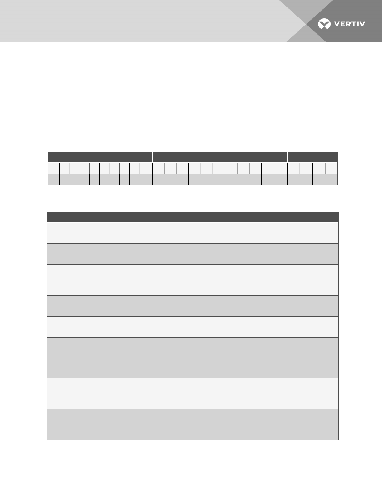
Table 2.2 below describes each digit of the 25 digitconfigurationnumber. The 14 digit model number consists of the first
10 digits and last four digits of the configuration number.
Table 2.1 Liebert® MCV 25 Digit Configuration Number Example
Model # Part 1 Model Details Model # Part 2
1 2 3 4 5 6 7 8 9 1 0 11 1 2 13 14 15 16 1 7 18 19 20 21 22 23 24 25
M C V 3 3 0 E 2 A D 0 G 0 0 U 0 2 0 0 0 0 * * * *
Table 2.2 Liebert® MCV Model Number Digit Definitions
Digit Description
Digits 1 and 2 = Unit Family
MC = Microchannel Condenser
Digit3 Platform Size
V = V-coil arrangement
Digits 4-6 - Nominal Capacity, kW
330 = 330kW
440 = 440kW
Digit7 - Control/Fan Type
E = Premium c ontrol and EC fan
Digit8 - Refrigerant Circuits/System Refrigerant Type
2 = Dual refrigerantcircuit, R-410A
Digit9 - Power Supply
A = 460V /3ph / 60Hz
2 = 380V / 3ph / 60Hz
M = 380-415V / 3ph /50Hz
Digit10 - Packaging
D = Domestic, non-stackable
E = Export crating, non-stackable
Digit11 - Coil Coating
0 = None
C = E-coat (epoxy withUV topcoat)
2 N omenclature an d Componen ts
5
Page 10
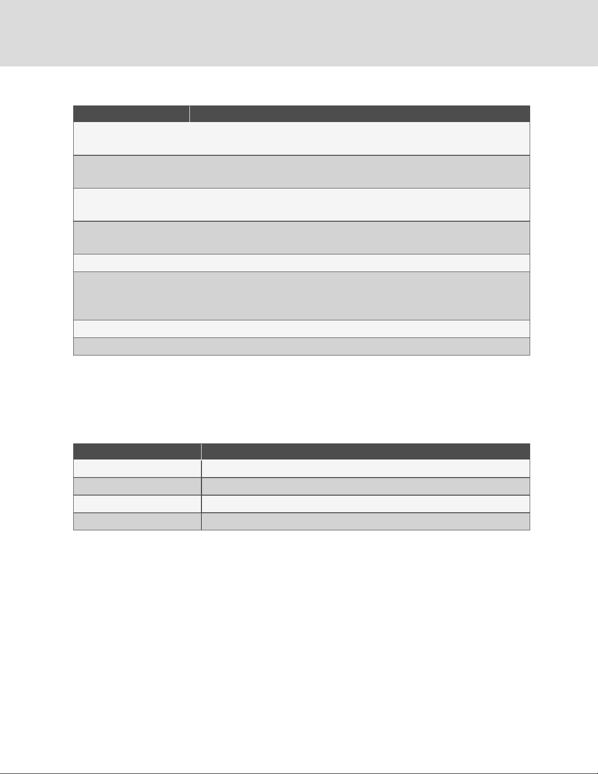
Table 2.2 Liebert® MCV Model Number Digit Definitions (continued)
Digit Description
Digit12 - Panel Material
G = Galvanizedsteel
Digit13 - Connection Pipe Unit of Measurement
0 = Inches (std. ACR copper)
Digit14 -Legs Included
0 = No legs (standard)
Digit15 - Agency Certification
U = CSA listed, marked with CSA c-uslogo
Digit16 -Undefined, Reserved for future use.
Digit17 - Receiver/Software Configuration
0 = Liebert® DSEsoftware, no receivers
2 = Liebert® DSEsoftware, withreceivers
Digits 1 8-21 - Undefined, Reserved for future use.
Digits 22-25 -Factory configuration number
2.2 Component Location
The unit component locations are described in the submittal documents included in Submittal Drawings on page61.
The following table lists the relevant documents by number and title.
Table 2.3 Heat Rejection Skid Component Location Drawings
Docu ment Number Title
DPN003888 Component Location Diagram, MCV330 +EconoPhase + Base Assembly
DPN003872 Component Location Diagram MCV330 (2) + EconoPhase (2) + Base Assembly
DPN00425 Component Location Diagram MCV440 +EconoPhase + Base Assembly
DPN004260 Component Location Diagram MCV440 (2)+ EconoPhase +Base Assembly
6
Vertiv | Lieb ert® MCV Installer/User Guide
Page 11

2.3 Product Description and Features
The Liebert® MCV condenser is a direct drive EC fan type, air cooled heat rejection unit suitable for mounting outdoors. It
provides heat rejection for two separate refrigeration circuits, matches the heat rejection capacity corresponding with the
outdoor ambient temperature and with each corresponding compressor heat rejection requirements. Constructed with a
galvanized steel frame, galvanized steel panels, and aluminum microchannel coil, the unit is quiet and corrosion resistant.
The condenser is quickly and easily installed, because all internal wiring is completed at the factory with only electrical
connections to be made at the job site. All electrical connections and controls are enclosed in an integral, weatherproof
section of the condenser.
Figure 2.1 Liebert® MCV Heat Rejection Skid
2.3.1 Control, Fan Types and Features
Premium Efficiency Control/EC Fan
Premium Efficiency Controls and EC fans are matched to provide superior system energy efficiency. The premium control
board allows CANbus communication with the indoor unit’s Liebert®iCOM™ control. This communication feature provides
compressor run signals, condenser operating mode changes, condenser alarm monitoring, simplified system charging
procedures and outdoor temperature monitoring.
The Premium Efficiency Control board on a Liebert®MCV controls EC fans on the same circuit to the same speed to
maintain refrigerant head pressure in DX mode and refrigerant temperature in EconoPhase mode.
2 N omenclature an d Componen ts
7
Page 12

Anti-Freezing Operation
The EC fans must be operated periodically in cold weather to reduce the possibility of lock up due to ice and snow
accumulation. During periods of fan inactivity and outdoor temperatures below 35°F (1.6°C), the EC fans will spin for at least
30 seconds every 15 minutes at 60% of the maximum fan speed.
Surge Protective Device
An optional Surge Protective Device (SPD) can be field wired to protect the condenser from power surges that threaten
sensitive equipment. The condenser’s electrical panel provides a terminal block to allow the SPD to be wired in parallel with
the high voltage power. An additional low voltage terminal block is provided on condensers to allow monitoring of the SPD
alarm circuit.
ASCO Series 420 surge protective device provides 50kA per mode of surge current protection. An illuminated green LED
indicates the SPD is on and operating properly. An illuminated red LED indicates that the device may require replacement.
When both LEDs are off, there is no power to the condenser, either from a power failure or because the condenser disconnect
is in the off position.
8
Vertiv | Lieb ert® MCV Installer/User Guide
Page 13

3 PRE-INSTALLATION PREPARATIONANDGUIDELINES
The unit dimensions, pipe connection locations, and piping schematics are described in the submittal documents included
in the Submittal Drawings on page61.
• Install the condenser in a location offering maximum security and access for maintenance.
• Avoid ground level sites with public access and areas prone to heavy snow or ice accumulations.
• To ensure adequate air supply, we recommend that condensers be installed in an area with clean air, away from
loose dirt and foreign matter that might clog the coil. In addition, condensers should be located no closer than
3 ft. (1m) from a wall, obstruction or adjacent unit.
• For roof installation, mount the condenser on suitable curbs or other supports in accordance with local codes.
• Locations that require additional coil-corrosion protection, such as coastal regions, heavy industrial, or
agricultural air pollution, should specify coils with the optional epoxy e-coat.
• Condensers must not be installed in a pit.
• Condensers must be installed on a level surface to ensure proper refrigerant flow.
• The Liebert® MCV heat rejection skid cannot be installed below the evaporator.
• The DA125 through DA250 are used with a Liebert® MCV heat rejection skid with receiver tanks. For this
system, the outlet of the receivers on the outdoor Liebert® MCV heat rejection skid must be higher than the
elevation of the electronic (EEV) valves inside of the indoor unit. If the vertical height of the receiver outlet is
greater than 60 ft. (18.3m) above the EEV, consult the factory. Refer to DPN003965 in Submittal Drawings on
page61.
• The DA265 is used with a Liebert® MCV heat rejection skid without receiver tanks. For these systems, the
bottom of the condenser coil on the outdoor Liebert® MCV heat rejection skid must be higher than the
elevation of the EEVs inside of the indoor unit. If the vertical height between the condenser coil bottom and the
EEV is greater than 60 ft. (18.3m), consult the factory. Refer to DPN005207 in Submittal Drawings on page61.
• Condensers must be installed in vertical airflow orientation to maintain the NEMA 3R rating of the electrical
box.
3 Pre-install ation Preparationan dGuideli nes
9
Page 14
3.1 Planning Dimensions
The condenser dimensions are described in the submittal documents included in the Submittal Drawings on page61.
Condensers mounted above and below the relative elevation of the indoor unit must follow the guidelines found in the
submittal drawings listed in the table below.
The following table lists the relevant documents by number and title.
Table 3.1 Dimension Planning Drawings
Docu ment Number Title
Heat Rejection Skid Dimensions
DPN003889 Cabinet and Anchor Dimensional Data MCV330 +EconoPhase + Base Assembly
DPN003875 Cabinet and Anchor Dimensional Data MCV330 (2) + EconoPhase (2) + Base Assembly
DPN004259 Cabinet and Anchor Dimensional Data MCV440 + EconoPhase +Base Assembly
DPN004261 Cabinet and Anchor Dimensional Data MCV440 (2)+ EconoPhase (2)+ Base Assembly
Condenser Elevation Above/Below Unit
DPN003965 Air Cooled Piping Schematic Liebert®MCV Mounted Above Liebert® DA125-D250
DPN005207 Air CooledPiping Schema tic Liebert® MCV MountedAbove Liebert® DA265
3.2 Unit Weights
Table 3.2 Liebert® MCV Heat Rejection Skid with EconoPhase Approximate Weights
Model
MCV330+PRE with Receiver 6 1
MCV330+PRE with Receiver 12 2
MCV440+PRE with Receiver 8 1
MCV440+PRE with Receiver 16 2
MCV440 + P RE without Receiver 8 1
MCV440 + P RE without Receiver 16 2
Numb er of Fans
on Heat Rejection Skid
Numb er of MCV /PRE Pairs
onHeat Rejection Skid
Dom estic Shipp ing
Weight lb
(kg)
5,00 0
(2,268)
10, 000
(4,535)
5,900
(2,676)
11,580
(5,252)
5,900
(2,676)
11,580
(5,252)
Dry Weight, lb (kg)
4,980
(2,258)
9,980
(4,526)
5,880
(2,667)
11,560
(5,243)
5,780
(2.621)
11,360
(5,152)
10
Vertiv | Lieb ert® MCV Installer/User Guide
Page 15
4 EQUIPMENT INSPECTION AND HANDLING
WARNING! Risk of improper moving, lifting, or handling of the unit. Can cause equipment damage, injury or
death. Read all of the following instructions and verify that all lifting and moving equipment is rated for the
weight of the unit before attempting to move, lift, remove packaging from or prepare the unit for installation.
See Table 3.2 on page10
CAUTION: Risk of contact with sharp edges, splinters, and exposed fasteners. Can cause injury. Only
properly trained and qualified personnel wearing appropriate, OSHA-approved PPE should attempt to move,
lift, remove packaging from or prepare the unit for installation.
NOTICE
Risk of improper lifting. Can cause equipment damage. Make sure that the spreader bars are wider than the
unit. If the spreader bars are too short, the slings may crush the unit.
NOTICE
Risk of damage from forklift. Can cause unit damage. Keep tines of the forklift level and at a height suitable to
fit below the skid and/or unit to prevent exterior and/or underside damage.
NOTICE
Risk of improper storage. Keep the unit upright, indoors and protected from dampness, freezing temperatures
and contact damage.
Upon arrival of the unit and before unpacking:
• Verify that the labeled equipment matches the bill of lading.
• Carefully inspect all items for visible or concealed damage.
• Report damage immediately to the carrier and file a damage claim with a copy sent to Vertiv or to your sales
representative.
4.1 Packaging Material
All material used to package this unit is recyclable. Please save for future use or dispose of the material appropriately.
4.2 Lift Points for Moving the Skid
Refer to the appropriate submittal drawings to locate the lift points for your heat rejection skid located in the Submittal
Drawings on page61.
• Use the indicated lifting points to lift the unit.
• Use spreader bars and/or shimmed blocks to prevent external damage.
• Lift the unit level. Tilting or twisting can damage internal components.
• Use the proper rigging equipment and make sure that attachment and lifting at the designated points is
vertical.
4 Equipmen t Inspection and Hand ling
11
Page 16
The following table lists the submittal documents by title and number.
Table 4.1 Heat Rejection Skid Drawings
Document Number Title
DPN003882 Cabinet Lifting Points MCV330 + EconoPhase + Base Assembly
DPN003883 Cabinet Lifting Points MCV330 (2) + EconoPhase (2) + Base Assembly
DPN004256 Cabinet Lifting Points MCV440 + EconoPhase + Base Assembly
DPN004263 Cabinet Lifting Points MCV440 (2) +EconoPhase (2) +Base Assembly
4.3 Removing Shipping Panels and Brackets
Shipping panels and securing brackets are located on each end of the unit. Before operating the unit, remove the panels and
brackets from both ends of the unit, Figure 4.1 below.
Figure 4.1 Shipping Panels and Securing Brackets to Remove
Item Description
1 4 panels on each end, 8 total.
2 3 brackets on each end, 6 total.
12
Vertiv | Lieb ert® MCV Installer/User Guide
Page 17
5 PIPING
All refrigeration connections to the unit are sweat copper. Factory installed piping brackets must not be removed. Field
installed piping must be installed in accordance with local codes and must be properly assembled, supported, isolated and
insulated.
Refer to specific text and to the submittal documents included in Submittal Drawings on page61, for other unit specific
piping requirements.
The following tables list the relevant documents by number and title.
Table 5.1 Piping General Arrangement Drawings
Docu ment Number Title
DPN004476 Piping Schematic DA125, DA150, and DA250 with Liebert®MCV
DPN005206 Piping Schematic DA265 with Liebert® MCV
Table 5.2 Piping Arrangements Liebert® MCV Condenser and Liebert® EconoPhase Pump Locations
Docu ment Number Title
DPN003965 Air Cooled PipingSchematic Liebert®MCV Mounted Above Liebert® DA125-D250
DPN005207 Air Cooled Piping Schematic Liebert® MCV Mounted Above Liebert®DA265
Table 5.3 Piping Connection Drawings
Docu ment Number Title
DPN003887 Primary Connection Locations MCV330 +EconoPhase + Base Assy. 460V and 575v
DPN004954 Primary Connection Locations MCV330 + EconoPhase + Base Assy. 380V and 415V
DPN004953 Primary Connection LocationsMCV330 (2)+ EconoPhase +Base Assy. 380V and 415V
DPN003878 Primary Connection Locations MCV330 +EconoPhase (2) +Base Assy. 460V and 575V
DPN004257 Primary Connection Locations MCV440 +EconoPhase + Base Assembly
DPN004262 Primary Connection Locations MCV440 (2) + EconoPhase (2) + Base Assembly
5.1 Refrigerant Piping and Charging
WARNING! Risk of over pressurization of the refrigeration system. Can cause explosive discharge of high
pressure refrigerant, loss of refrigerant, environmental pollution, equipment damage, injury, or death. This
unit contains fluids and gases under high pressure. Use extreme caution when charging the refrigerant
system. Do not pressurize the system higher than the design pressure marked on the unit's nameplate.
Consult local building and plumbing codes for installation requirements of additional pressure relief devices when isolation
valves are field installed. Do not isolate any refrigerant circuits from over pressurization protection.
5 Pip ing
13
Page 18
NOTICE
Risk of oil contamination with water. Can cause equipment damage.
Liebert®MCV systems require the use of POE (polyolester) oil. POE oil absorbs water at a much faster rate
when exposed to air than previously used oils. Because water is the enemy of a reliable refrigeration system,
extreme care must be used when opening systems during installation or service. If water is absorbed into the
POE oil, it will not be easily removed and will not be removed through the normal evacuation process. If the oil
is too wet, it may require an oil change. POE oils also have a property that makes them act as a solvent in a
refrigeration system. Maintaining system cleanliness is extremely important because the oil will tend to bring
any foreign matter back to the compressor.
Table 5.4 System Refrigerant Pressures
Maximum Design Operating Pressure (High Side) 530 psig 3655 kPa N oted on the unit serial tag
5.1.1 Refrigerant Piping Guidelines for Air Cooled Systems
• Field installed interconnecting piping should be properly selected based on local codes and unit labeling.
• Air cooled units and condensers ship with an inert gas holding charge. Do not vent the charge until all
refrigerant piping is in place, ready for connection to the unit and condenser.
• Use copper piping with a brazing alloy with a minimum temperature of 1350°F (732°C), such as Sil-Fos. Avoid
soft solders, such as 50/50 or 95/5.
• Use a flow of dry nitrogen through the piping during brazing to prevent formation of copper oxide scale inside
the piping. When copper is heated in the presence of air, copper oxide forms. POE oils will dissolve these
oxides from inside the copper pipes and deposit them throughout the system, clogging filter driers and
affecting other system components.
• A pure dry nitrogen flow of 1-3 ft3/min (0.5-1.5 l/s) inside the pipe during brazing is sufficient to displace the air.
Control the flow using a suitable measuring device.
• Ensure that the tubing surfaces to be brazed are clean and that all burrs have been removed from the ends of
the tubes.
• Ensure that all loose material has been cleaned from inside the tubing before brazing.
• Protect all refrigerant line components within 18in. (460mm) of the brazing site by wrapping them with a wet
cloth or with a suitable heat-sink compound.
• Isolate piping from building using vibration isolating supports.
• The Liebert® MCV heat rejection skid cannot be installed below the evaporator.
• The DA125 through DA250 are used with a Liebert® MCV heat rejection skid with receiver tanks. For these
systems, the outlet of the receivers on the outdoor Liebert® MCV heat rejection skid must be higher than the
elevation of the electronic expansion valves (EEV0 inside of the indoor unit. If the vertical height of the receiver
outlet is greater than 60 ft. (18.3m) above the EEV, consult the factory. Refer to DPN003965 in Submittal
Drawings on page61.
• The DA265 is used with a Liebert® MCV heat rejection skid without receiver tanks. For these systems, the
bottom of the condenser coil on the outdoor Liebert® MCV heat rejection skid must be higher than the
elevation of the EEVs inside of the indoor unit. If the vertical height between the condenser coil and the EEV is
greater than 60 ft (18.3m), consult the factory. Refer to DPN005207 in Submittal Drawings on page61.
• Install traps on hot gas (discharge) lines at the base of the vertical risers over 5 ft. (1.5m) and then for vertical
risers over 25 ft (7.6m). Install a trap in 20 ft. (6m) increments or evenly divided over the vertical rise. The
DA250 and DA265 each have piping out of the top of the unit with internally installed traps on the hot gas lines.
• Consult factory for piping lengths exceeding the lengths in Table 5.5 on the facing page.
14
Vertiv | Lieb ert® MCV Installer/User Guide
Page 19
Table 5.5 Piping Lengths
Indoo r Unit Maximum Actual Leng th Maximum Equivalent Length
DA250, DA265 200 ft. (61m) 300 ft. (91m)
DA125, DA150, DA165 300 ft. (91m) 450(137.2m)
• Pitch horizontal hot gas piping down at a minimum rate of 1/2in.per 10ft (42mm per 10m) so that gravity will
aid in moving oil in the direction of refrigerant/oil flow.
• Keep piping clean and dry, especially on units with R-410A refrigerant.
• Avoid piping runs through noise sensitive areas.
• Do not run piping directly in front of discharge air stream.
• Refrigerant oil – do not mix oil types. Consult the indoor-unit installation/user guide for refrigerant type and oil
requirements.
Refer to ASHRAE Refrigeration Handbook for general, good practice refrigeration piping. The indoor cooling unit has a
factory installed high pressure safety switch in the high side refrigerant circuit. A fusible plug is installed in each Liebert®
DSE receiver.
NOTE: Liebert® DSE systems require all indoor and outdoor field refrigerant piping to be insulated 1/2 in. minimum.
All outdoor insulation must be UV and ozone resistant.
• Refer to the indoor unit's Installer/User Guide, for recommended refrigerant piping sizes based on equivalent
pipe lengths.
• Refer to the indoor unit's Installer/User Guide for the refrigerant-charge requirements of the system.
5.1.2 Refrigerant Charge Requirements
Table 5.6 Approximate R-410A Refrigerant Required per Circuit for MCV Heat Rejection Skid
Heat Rejection Skid System No . Circuit No.
1
MCV330 Single skid with (1) PRE unit 1
2
1
MCV440 Single skid with (1) PRE unit 1
2
with or witho ut Receivers lb (kg)
Charge per Circuit
52
(24.6)
62
(28.1)
5 Pip ing
15
Page 20
Table 5.6 Approximate R-410A Refrigerant Required per Circuit for MCV Heat Rejection Skid (continued)
Heat Rejection Skid System No . Circuit No.
MCV330 Dual skid with (2) PRE units
MCV440 Dual skid with (2) PRE units
*The heat rejection skid contains:
• MCV condensers.
• DSE receivers, when used with a DA125 through DA250 system.
• EconoPhase (PRE)units, and all internal piping.
Liebert®DSE receivers are not used with a DA265 system.
1
2
1
2
1
2
1
2
1
2 62
1
2
Charge per Circuit
with or witho ut Receivers lb (kg)
52
(24.6)
(28.1)
5.1.3 Additional Oil Requirements
Refer to the indoor unit's Installer/User Guide to determine if additional oil is required for each circuit. The need for
additional oil is affected by compressor type, piping lengths, receiver, and total refrigerant charge.
5.2 System Dehydration/Leak Test
Refer to the indoor unit's Installer/User Guide for the leak check and evacuation procedures for the entire thermalmanagement system. Refer to the section that refers to the winter control system used on the condenser.
5.3 Charging for Condensers
Refer to the Liebert® DSE Installer/User Guide for the leak check and evacuation procedures for the entire thermalmanagement system.
16
Vertiv | Lieb ert® MCV Installer/User Guide
Page 21

6 ELECTRICAL CONNECTIONS
Line voltage electrical service is required for all models. Electrical service must conform to national and local electrical
codes. Refer to equipment nameplate regarding wire size and circuit protection requirements. Refer to electrical schematic
when making connections. Refer the appropriate submittal drawing, listed in Table 6.1 on the next page, for electrical
service entrances into unit.
A manual electrical disconnect switch should be installed in accordance with local codes and distribution system. Consult
local codes for external disconnect requirements.
All internal wiring is completed at the factory.
WARNING! Arc flash and electric shock hazard. Open all local and remote electric power supply disconnect
switches, verify with a voltmeter that power is Off and wear appropriate, OSHA-approved personal protective
equipment (PPE) per NFPA 70E before working within the electric control enclosure. Failure to comply can
cause serious injury or death. Customer must provide earth ground to unit, per NEC, CEC and local codes, as
applicable. Before proceeding with installation, read all instructions, verify that all the parts are included and
check the nameplate to be sure the voltage matches available utility power. The Liebert® controller does not
isolate power from the unit, even in the Unit Off mode. Some internal components require and receive power
even during the Unit Off mode of the controller. The only way to ensure that there is NO voltage inside the
unit is to install and open a remote disconnect switch. Refer to unit electrical schematic. Follow all local
codes.
WARNING! Risk of improper wiring, piping, moving, lifting and handling. Can cause equipment damage,
serious injury or death. Installation and service of this equipment should be done only by qualified personnel
who have been specially trained in the installation of air conditioning equipment and who are wearing
appropriate, OSHA-approved PPE.
WARNING! Risk of improper wire sizing/rating and loose electrical connections. Can cause overheated wire
and electrical connection terminals resulting in smoke, fire, equipment and building damage, injury or death.
Use correctly sized copper wire only and verify that all electrical connections are tight before turning power
On. Check all electrical connections periodically and tighten as necessary.
NOTICE
Risk of improper power supply connection. Can cause equipment damage and loss of warranty coverage.
Prior to connecting any equipment to a main or alternate power source (for example: backup generator
systems) for start up, commissioning, testing, or normal operation, ensure that these sources are correctly
adjusted to the nameplate voltage and frequency of all equipment to be connected. In general, power source
voltages should be stabilized and regulated to within ±10% of the load nameplate nominal voltage. Also, ensure
that no three phase sources are single phased at any time.
NOTE: Use copper wiring only. Make sure that all connections are tightened to the proper torque mentioned on the
component.
The electrical connections are described in the submittal documents included in the Submittal Drawings on page61.
6 Electrical Connections
17
Page 22
The following table lists the relevant documents by number and title.
Table 6.1 Electrical Field Connection Drawings
Docu ment Number Title
DPN003879 Electrical Panel Layout MCV330
DPN004212 Electrical Panel Layout, MCV440 Condenser Section
DPN003887 Primary Connection Locations MCV330 +EconoPhase + Base Assy. 460V and 575v
DPN003878 Primary Connection Locations MCV330 +EconoPhase + Base Assy. 460V and 575V
DPN004954 Primary Connection Locations MCV330 + EconoPhase + Base Assy. 380V and 415V
DPN004953 Primary Connection Locations MCV330 (2)+EconoPhase + Base Assy. 380V and 415V
DPN004257 Primary Connection Locations MCV440 + EconoPhase + Base Assembly
DPN004262 Primary Connection Locations MCV440 (2) +EconoPhase (2) +Base Assembly
DPN003886 CANbus a nd Interlock ConnectionsLiebert®MCV + Liebert® EconoPhase + Base Assy.
6.1 Line Voltage Wiring
WARNING! Risk of electrical fire and short circuit. Can cause property damage, injury or death. Select and
install the line side electrical supply wire and overcurrent protection device(s) according to the specifications
on the unit nameplate(s), per the instructions in this manual and according to the applicable national, state
and local code requirements. Use copper conductors only. Verify that all electrical connections are tight. Unit
specific wiring diagrams are provided on each unit.
Risk of improper power supply connection. Can cause equipment damage and loss of warranty coverage.
Prior to connecting any equipment to a main or alternate power source (for example: backup generator
systems) for start up, commissioning, testing, or normal operation, ensure that these sources are correctly
adjusted to the nameplate voltage and frequency of all equipment to be connected. In general, power source
voltages should be stabilized and regulated to within ±10% of the load nameplate nominal voltage. Also, ensure
that no three phase sources are single phased at any time.
NOTE: For acceptable and unacceptable power supplies, see Wye vs. Delta Connected Power Supply on page20.
Condenser rated voltage should be verified with available power supply before installation. Refer to the unit’s electrical
schematic and serial tag for specific electrical requirements.
18
Vertiv | Lieb ert® MCV Installer/User Guide
Page 23
Liebert® MCV condenser power connections are provided for three phase wires and one earth ground wire. Line voltage
electrical service is required for all condensers at the location of the condenser. The voltage supply to the condenser may
not be the same voltage supply as required by the indoor unit. Consider using a UPS on both indoor cooling units and MCV
condensers to maintain uninterrupted cooling capability. Refer to the unit’s serial tag for specific condenser electrical
requirements. A unit disconnect is standard. However, a site disconnect may be required by local code to isolate the unit for
maintenance. Route the supply power to the site disconnect switch and then to the unit. Route the conduit to the knockout
provided in the bottom right end of the electrical control enclosure. Connect the earth ground wire lead to the marked earth
ground connection terminal provided near the factory installed disconnect switch per the appropriate drawing in the
Submittal Drawings on page61.
NOTE: A separate neutral wire does not need to be run to the Liebert® MCV Condenser.
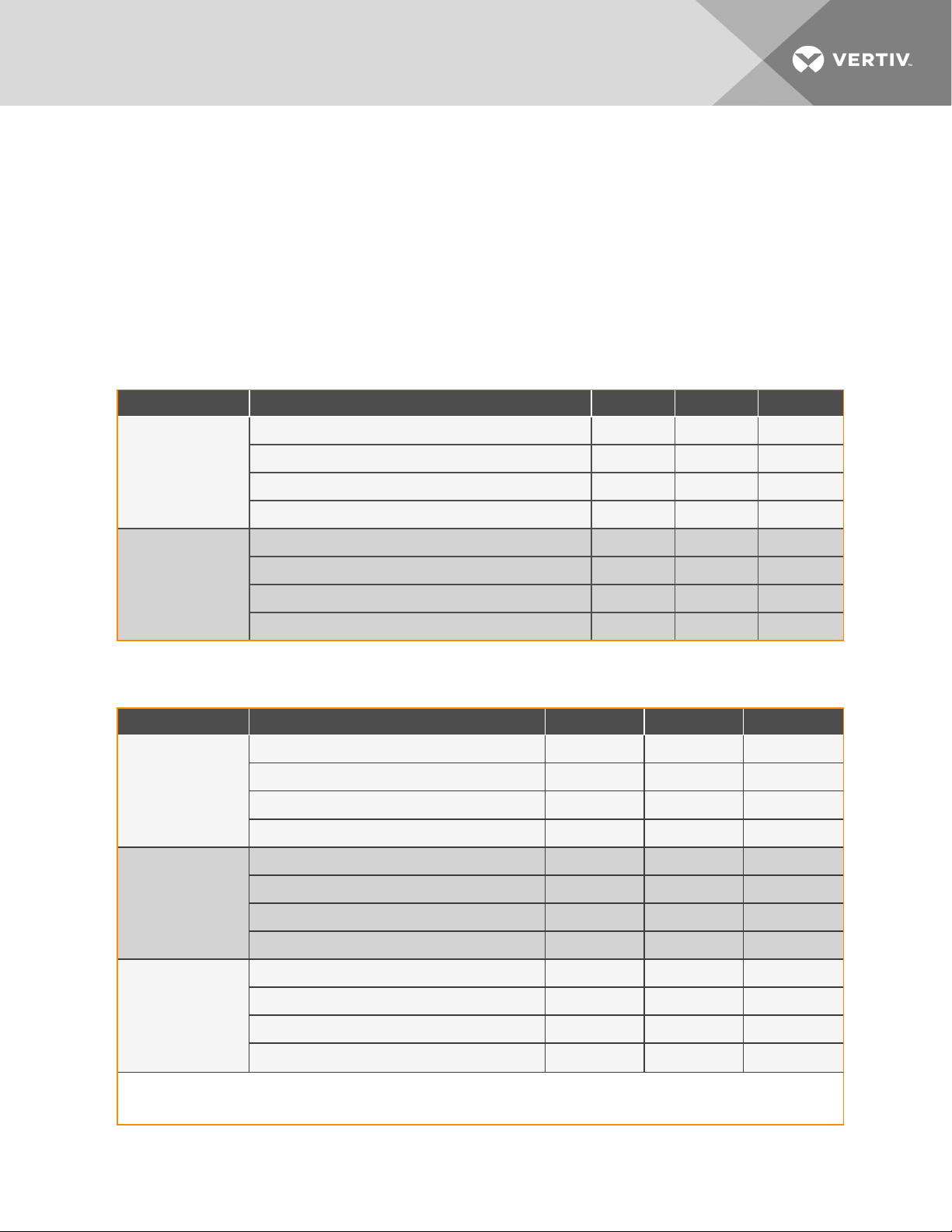
Table 6.2 Liebert® MCV Condenser Only Electrical Data, 3 Phase
Model Voltage FLA WSA OPD
2 = 380V / 60Hz 21.0 21.9 25
MCV330
MCV440
A = 460V /60Hz 1 6.8 17.5 20
M = 380-415V / 50Hz 21. 0 21 .9 25
G = 415V / 50Hz 21 .0 21. 9 25
2 = 380V / 60Hz 28.0 28.9 30
A = 460V /60Hz 22. 4 23.1 25
M = 380-415V / 50Hz 28.0 28.9 30
G = 415V / 50 Hz 28.0 28.9 30
Table 6.3 Liebert® Heat Rejection Skid Electrical Data, 3 Phase
Model Voltage FLA WSA OPD
2 = 380V / 60Hz 29.4 30.5 35
MCV330 + PR1 25
MCV330 + PR200
A = 460V /60Hz 23.8 24.7 25
G = 415V / 50Hz 28.4 29.3 30
B = 575V /60Hz 19.0 1 9.7 30
2 = 380V / 60Hz NA NA NA
A = 460V /60Hz 21.4 22. 1 25
G = 415V / 50Hz N/A N/A N/A
FLA = Full Load Amps; WSA = Wire Size Amps; OPD = Ma ximum Ov ercurrent Protection Device.
Source: DPN005045 Rev . 1
6 Electrical Connections
B = 575V /60Hz N/A N /A N /A
2 = 380V / 60Hz 36.4 37.5 40
A = 460V /60Hz 29.4 30.3 35
MCV440 + P RE
G = 415V / 50Hz 35.4 36.3 40
B = 575V /60Hz 23.5 24.2 35
19
Page 24
NOTE: Heat rejection skids with 12 or 16 fans contain two 3 phase connection boxes, and each box requires a separate
supply input per Table 6.3 on the previous page.
6.2 Wye vs. Delta Connected Power Supply
Acceptable Power Supplies—380V to 460V Nominal Units
• 380V wye with solidly grounded neutral and 220V line to ground
• 480V wye with solidly grounded neutral and 277V line to ground
• Wye with high resistance (or impedance) ground
• Delta with corner ground
Unacceptable Power Supplies
• Delta without ground or with floating ground
• Delta with grounded center tap
6.3 Low Voltage Control Wiring—CANbus Communication
NOTICE
Risk of control malfunction. Can cause improper unit operation.
Verify that all low voltage electrical wiring has been performed per the schematic diagram provided and that
all low voltage wiring connections are tight.
CANbus communication and interlock wiring are required between the indoor and the outdoor units. CANbus cables are
supplied by others to connect the indoor unit to the outdoor condenser. No special considerations are required when the
total external cable connection between the indoor unit and outdoor unit is less than 450ft(137m). A CANbus isolator is
required for total external cable connections longer than 450ft(137m) but less than 800ft(243m).
The control wiring connections are described in the submittal documents included in the Submittal Drawings on page61.
The following tables list the relevant documents by number and title.
Table 6.4 CANbus Communication Connection Drawings
Docu ment Number Title
DPN003886 CANbus and Interlock Connections between Unit and Condenser
20
Vertiv | Lieb ert® MCV Installer/User Guide
Page 25

7 CHECKLIST FOR COMPLETED INSTALLATION
7.1 Moving and Placing Equipment
1. Unpack and check received material.
2. Proper clearance for service access has been maintained around the equipment.
3. Equipment is level and mounting fasteners are tight.
7.2 Electrical Installation Checks
1. Line voltage connected and matches equipment nameplate.
2. Power line circuit breakers or fuses have proper ratings for equipment installed.
3. CANbus communication and interlock wiring connections completed between indoor cooling unit and
condenser.
4. All internal and external high and low voltage wiring connections are tight.
5. Confirm that unit is properly grounded to an earth ground.
6. Control transformer setting matches incoming power.
7. Electrical service conforms to national and local codes.
8. Verify that the condenser is not connected to an unacceptable power supply, see Wye vs. Delta Connected
Power Supply on page20.
9. Verify that the CANbus wiring, CANbus END of Line jumper position, and the CANbus Device Address DIP
Switch setting are correct according to the application at the job site.
10. Verify that terminals 70, 71, (and 230 when applicable) are used and properly wired for interlock wiring,
particularly on systems that use two condensers for one indoor unit.
7.3 Piping Installation Checks
1. Piping completed to corresponding indoor cooling unit refrigeration circuit.
2. Piping is leak checked, evacuated and charged with specified refrigerant.
3. Additional refrigerant oil is added per circuit, if required.
4. Piping is properly sized, sloped, and trapped for proper oil return.
5. Check piping inside and outside of equipment for proper support and adequate spacing to prevent rub
through or chafing.
7.4 Other Installation Checks
1. Installation materials and tools have been removed from equipment (literature, shipping materials, construction
materials, tools, etc.).
2. Locate blank start up sheet, ready for completion by installer or startup technician.
7 Ch ecklist for Completed Installation
21
Page 26

This page intentionally left blank
22
Vertiv | Lieb ert® MCV Installer/User Guide
Page 27

8 INITIAL START UP CHECKS ANDCOMMISSIONINGPROCEDURE
FORWARRANTYINSPECTION
WARNING! Arc flash and electric shock hazard. Open all local and remote electric power supply disconnect
switches, verify with a voltmeter that power is Off and wear appropriate, OSHA-approved personal protective
equipment (PPE) per NFPA 70E before working within the electric control enclosure. Failure to comply can
cause serious injury or death. Customer must provide earth ground to unit, per NEC, CEC and local codes, as
applicable. Before proceeding with installation, read all instructions, verify that all the parts are included and
check the nameplate to be sure the voltage matches available utility power. The Liebert® controller does not
isolate power from the unit, even in the Unit Off mode. Some internal components require and receive power
even during the Unit Off mode of the controller. The only way to ensure that there is NO voltage inside the
unit is to install and open a remote disconnect switch. Refer to unit electrical schematic. Follow all local
codes.
WARNING! Risk of improper wiring, piping, moving, lifting and handling. Can cause equipment damage,
serious injury or death. Installation and service of this equipment should be done only by qualified personnel
who have been specially trained in the installation of air conditioning equipment and who are wearing
appropriate, OSHA-approved PPE.
WARNING! Risk of contact with high speed rotating fan blades. Can cause serious injury or death. Open all
local and remote electric power supply disconnect switches, verify with a voltmeter that power is off, and
verify that all fan blades have stopped rotating before working in the unit cabinet or on the fan assembly. If
control voltage is applied, the fan motor can restart without warning after a power failure. Do not operate the
unit with any or all cabinet panels removed.
CAUTION: Risk of exposure to harmful noise levels. Can cause hearing injury or loss. Depending on the
installation and operating conditions, a sound pressure level greater than 70dB(A) may arise. Take
appropriate technical safety measures. Operating personnel must wear appropriate, OSHA-approved PPE
and observe all appropriate hearing-protection safety requirements.
• Confirm that all items on Checklist for Completed Installation on page21 have been done.
• Locate the “Liebert® MCV Warranty Inspection Check Sheet” in the unit’s electric panel. (PSWI-8542-408CO).
• Complete the “Liebert® MCV Warranty Inspection Check Sheet” during start-up. (PSWI-8542-408CO).
• Forward the completed “Liebert® MCV Warranty Inspection Check Sheet” to your local sales office. This
information must be completed and forwarded to validate warranty.
• Contact your local sales representative or technical support if you have any questions or problems during unit
start-up and commissioning. Visit https://www.Vertiv.com/en-us/support/ or call 1-800-543-2778 for contacts.
8 Initial S tart up Checks and Commissi oning Procedure forWarrantyIns pection
23
Page 28

This page intentionally left blank
24
Vertiv | Lieb ert® MCV Installer/User Guide
Page 29
9 TROUBLESHOOTING
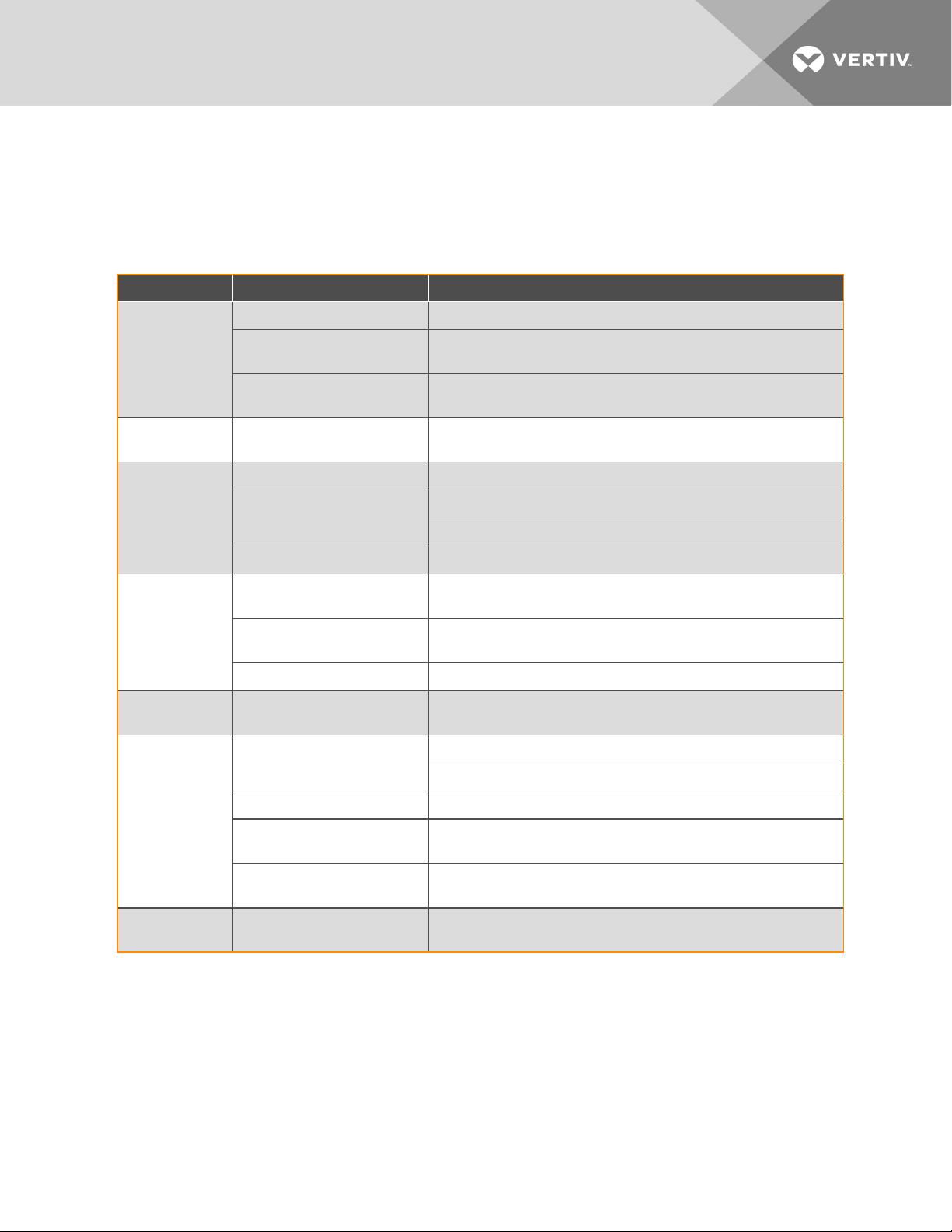
When an EconoPhase unit triggers an alarm, please refer to the Liebert® EconoPhase Installer/User Guide available on the
product page at www.Vertiv.com.
Table 9.1 Troubleshooting MCV Condenser Section
Symptom Possible cause Ch eck or Remedy
No power to condenser. Check voltage at input terminal block.
Condenser will not
start
Low discharge
pressure
High discharge
pressure
SPD green and red
LEDs are extinguished
SPD red LED is
illuminated
Circuit breaker or fuse for low voltage
transformer in condenser is tripped.
No low voltage signal to/from indoor
unit.
Faulty head pressure control valve or
premium efficiency control board.
Dirty condenser f ins. Clean coil.
Condenser fans not operating.
High refrigerant charge Check refrigerant charge.
No voltage or improper phasing exists
at condenser.
Electrical connectionsto SPD are
faulty.
Condenser disconnect is turned O ff. Recheck lights with disconnect switch in the On position.
A surge exceeding the rating of the
SPD has occurred.
Connection to P24 is loose or
disconnected.
Locate problem in condenser electrical panel and repair.
Locate open circuit and repair.
Replace if defective.
Check for low voltage signal from indoor unit.
Check fan motors and fuses.
Check voltage at input terminal block.
Locate connection problem and repair.
Replace SPD and inspect other components for damage and replace them if
necessary.
Check the connection to P24 to verify that is connected securely.
Check the connector from the transformer for loose terminals.
9 Troubleshooting
Control Board LEDs
do not light.
Fan will not run
Fuse loca ted next to P24 has blown. Verify that the fuses next to P24 hav e not blown. Replace as needed.
24V transformer has failed.
Premium Efficiency Control Board has
failed.
Jumper not installed between 24V and
DIN1 (for Ziehl-Abegg fan motor).
With a voltmeter verify that the output from the transformer is 24Vac ±10%. If the
value exceeds ±1 0%, verify that the correct primary leads are being used.
If there is no output v oltage, verify that the primary connections are secure and
receiving the correct voltage. If they are, replace the transformer.
Install jumper between 24V and DIN1 (for Z iehl Abegg fan m otor).
25
Page 30

This page intentionally left blank
26
Vertiv | Lieb ert® MCV Installer/User Guide
Page 31

10 CONTROL OPERATION
The Liebert® MCV Premium Efficiency Control takes about 30 seconds to boot during which time, the LED on the Premium
Efficiency Control Board reads “888.” When fully booted, “F00” displays, then the value for F00. When using the control, the
condenser fan(s) respond less than 5 seconds after receiving a compressor or signal from the indoor unit. Consider using
UPS equipment on both data center cooling units and Liebert® MCV condensers to maintain uninterrupted cooling
capability.
For the first 60 seconds of operation after the compressor turns on, the condenser fan(s) run at a factory set fixed speed,
based on ambient temperature: faster at higher temperatures, slower at lower temperatures. After 60 seconds, the control
adjusts the fan speed based on the liquid pressure transducer. If the liquid-pressure transducer fails, the condenser uses
temperature sensors to control the fan speed based on the liquid line temperature. The condenser fans continue to operate
for approximately 30 seconds after compressors turn Off.
The MCV fans have various alarm conditions, such as loss of voltage and loss of control signal, that stop the condenser fans.
When an alarm condition is no longer present the fans turn on automatically if compressors are On.
10.1 Liebert® EconoPhase Pumped RefrigerantEconomizer withaLiebert® DSE System
Liebert® DSE systems are designed to provide precision air conditioning to computer racks in a data center or computer
room as efficiently and effectively as possible.
A Liebert® DSE system with EconoPhase is composed of individually-shipped components or components assembled
together on skids. Some examples are:
System example 1
• Liebert® DSE—High efficiency, floor mounted indoor unit
• Liebert® MC Condenser—Air cooled microchannel condenser, premium version
• Liebert® EconoPhase—Liebert® EconoPhase pumped-refrigerant economizer (PRE)
System example 2
• Liebert® DSE—High efficiency, floor mounted indoor unit
• Liebert® MCV Heat rejection skid—Air cooled microchannel condenser, premium version with a
Liebert® EconoPhase pumped refrigerant economizer (PRE)
The Liebert® EconoPhase PRE is an add on module for use with an air cooled DSE system. The Liebert® EconoPhase allows
the system to switch to Liebert® EconoPhase operation when the outdoor temperature is low enough to provide the required
temperature difference between the inside air and the outside air, which, in turn, provides significant energy savings
because the compressor(s) do not operate. At lower temperatures, the system switches one or both circuits from
Compressor Mode to Pump Mode. The pump consumes roughly one-tenth of the power consumed by the compressor.
The Liebert® EconoPhase system maintains this energy efficiency by employing the heat absorption properties of a liquid
(pumped refrigerant) through a phase change. Refrigerant is pumped as a liquid, becomes a gas within the DSE evaporator
and is then returned to the condenser where it condenses to a liquid. The subcooled liquid refrigerant from the condenser is
run directly into the Liebert® EconoPhase pumps and circulates back to the DSE unit (see Figure 10.1 on the next page).
The system operates as a typical air cooled direct expansion system when outdoor ambient conditions are unfavorable to
EconoPhase operation. The pumps in the Liebert® EconoPhase PRE are turned off and bypassed during compressor
operation.
10 Control Op eration
27
Page 32
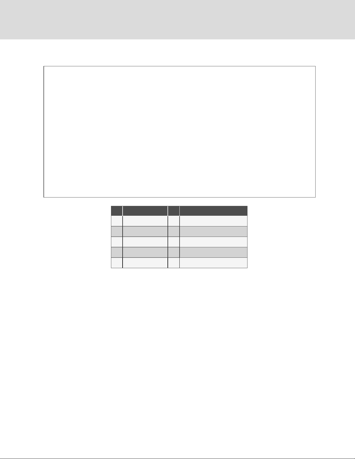
Figure 10.1 Liebert® EconoPhase Pumped Refrigerant Pressure Enthalpy Diagram
Item Description Item Description
1 Pressure 6 Condenser (DX mode)
2 Enthalpy 7 Indoor unit
3 Liquid 8 Condenser (pump mode)
4 Liquid/vapor m aximum 9 Traditional vapor compression cycle
5 Vapor 10 EconoPhase cycle
10.2 Overview of Operating Modes
Each circuit on a system combining a Liebert® EconoPhase, Liebert® DSE and Liebert® MCV condenser has 6 distinct
operating modes:
• Idling with compressor and pumps Off
• Start up
• Compressor operation
• Compressor to pump changeover
• Pump operation
• Pump to compressor changeover
28
Vertiv | Lieb ert® MCV Installer/User Guide
Page 33
A circuit will run most of the time in either compressor or pump operation mode. These modes both efficiently remove heat
from the conditioned space and reject it via the air cooled condenser. The flow paths during each mode of operation are
detailed in Compressorized Operation Flow Path below and Pump Operation Flow Path on the next page.
A couple of differences to note between Compressor Mode and Liebert® EconoPhase operation:
• The unit does not dehumidify in EconoPhase operation. If dehumidification is desired, EconoPhase operation
must be disabled.
• Bubbles may be seen in the site glass in the indoor unit when the system is in EconoPhase operation. This does
not necessarily mean the system is low on charge. Refer to the Liebert® DSE™ user manual (available at
www.Vertiv.com) for complete charging instructions for the Liebert® DSE/EconoPhase system.
Figure 10.2 Compressorized Operation Flow Path
Item Description Item Description
1 Check valve 5 Electronic expansion valve (EEV)
2 Condenser 6 Pump
3 Compressor 7 Solenoid valve
4 Evaporator
10 Control Op eration
29
Page 34
Figure 10.3 Pump Operation Flow Path
Item Description Item Description
1 Check valve 5 Electronic expansion valve (EEV)
2 Condenser 6 Pump
3 Compressor 7 Solenoid valve
4 Evaporator
10.3 Liebert®EconoPhase Operation
The EconoPhase unit enables the Liebert® DSE system to operate in any of threemodes to control temperature, depending
on the outdoor temperature and the load.
• Compressor Mode
• Pump Mode
• Mixed Mode
When the outdoor temperature becomes low enough to provide the required temperature difference between the inside air
and the outside air, there is no need to compress the refrigerant to a higher pressure/temperature. When the outdoor
temperature is low enough, the system switches from Compressor Mode to Pump Mode or to Mixed Mode.
• Compressor Mode: All available compressors may be used to maintain the control temperature. All the
available EconoPhase pumps are Off. The control will typically run in this mode when the load and
temperatures are such that full or partial EconoPhase operation is not possible, or because certain pumps have
experienced alarms.
• Pump Mode: All of the available pumps may be used to maintain the Control Temperature. All the compressors
in the system are Off. The control will typically run in this mode when load and temperatures permit.
• Mixed Mode: (Dual pump models only): The pump in Circuit 1 is On and the compressor(s) in Circuit 2 is On.
Some systems may not have Mixed Mode capability, depending on the manufacture date. Contact the factory
to inquire about a software upgrade.
30
Vertiv | Lieb ert® MCV Installer/User Guide
Page 35

10.3.1 Liebert® EconoPhase Control
Liebert® EconoPhase operation has three main controlled parameters:
• Room temperature
• Refrigerant temperature
• Pump pressure differential (outlet pressure - inlet pressure)
Room Temperature
When the system is in Pump Mode, the room temperature is controlled by modulating the pump speed with a variable
frequency drive. The load requirement will determine if one pump or two are needed. Figure 10.4 below, shows the
sequence of operation in terms of pump speed. Minimum speed is 45% and maximum speed is 100%. See Table 10.1 on
the next page, for more detail on the events depicted and the conditions that trigger action.
Figure 10.4 Two Circuit Pump Control
10 Control Op eration
31
Page 36
Table 10.1 Events and Actions of 2 Circuit Pump Control
Event Condition to Trigger Action Action
B to A
A to B
F to G
At E and H
upward
At E and H
downward
J to K
Pump 2 Early
Startup
Pump 2 O ff; and (Pump 1 at minimum speed for 60 sec.;
and
Delta T [indoorair tem perature - setpoint] <-4°F (2.2°C)
Both Pump 1 and Pump 2 Off
and
DeltaT>0°F 0°C)
Pump 2 O ff and P ump 1 at maximum speed for 600 seconds
and
Delta T >1°F (-0.6°C)
Pump 1 at maximum speed; and Pump 2 at minimum speed
and
Delta T >1°F (-0.6°C)
Pump 1 at maximum speed; and Pump 2 at minimum speed; and
Delta T <-1°F (-0.6°C)
Both Pump 1 and Pump 2 at minimum speed for 60 sec.
and
Delta T <-1°F (-0.6°C)
Pump 2 O ff
and
Delta T >2°F (1.1°C)
Pump 1 turns Off
Pump 2 rem ains O ff
Pump 1 turns On and runs on PID
Pump 2 rem ains O ff
Pump 2 turns O n a t starting speed, then goes to minimum speed
immediately.
Pump 1 continuesto run on PID
Pump 1 runs at maximum speed, while Pump 2 runs on PID
Pump 1 runs on PID, while Pump 2 runs at minimum speed
Pump 2 turns O ff, while P ump 1 runs at minimum speed
No action to Pump 1; turn On Pump 2 at 80% speed.
Once the start up procedure is finished, step change to minimum
speed imm ediately
In the case of a transition from Compressor Mode to Pump Mode, the pumps will be given initial speeds based on the call
for cooling at the time of transition. The pumps will go to this initial speed after the start-up routine is completed. This will
mean that, depending on the load, both pumps will start immediately at the transition to Pump Mode from Compressor
Mode.
When the system is in Mixed Mode, the room temperature is controlled either by modulating the digital compressor(s) on
Circuit 2 with the pump on Circuit 1 at 100%, or by modulating the pump speed on Circuit 1 with the compressor(s)
operating at the minimum digital percent.
Refrigerant Temperature
When a circuit is running in Pump Mode, the refrigerant temperature is controlled by the condenser fan speed. When a
circuit switches from Compressor Mode to Pump Mode, the condenser fan speed control changes from pressure control to
temperature control, with the controlled parameter being condenser outlet refrigerant temperature.
The default setpoint on Circuit 1 is 45°F, while on Circuit 2 it is 37°F. The condenser fan speed will modulate to provide the
respective temperature. But if the outdoor temperature is warm enough, or if the load is high enough, the fans might be at
100% and the actual refrigerant temperature might be above the setpoint. In that case, the temperature will depend on the
heat rejection capability of the condenser at the given conditions.
32
Vertiv | Lieb ert® MCV Installer/User Guide
Page 37

Actual fan speed will depend on the load and the outdoor temperature. The fan speed will be lower for a given heat load
with lower outdoor temperature in order to maintain the setpoint.
Because the refrigerant temperature could be below the dew point inside, the indoor piping must be insulated to prevent
condensation. In addition, the outdoor piping must be insulated so that heat is not lost to the outdoor air at very low ambient
temperatures, causing the refrigerant temperature to fall and increasing the possibility of frost at the evaporator.
Pump Pressure Differential
The pump pressure differential must to be maintained above a minimum for cooling and lubricating flow to be provided to
the pump motor and bearings. The differential is controlled by EEV position. When the system switches to EconoPhase
operation, the EEV control changes from superheat control to manual control. The Liebert® iCOM™ controller then signals
the EEV to control its position based on pump differential , unless during pump mode operation, the suction superheat
drops below the minimum acceptable level, then the EEV will begin to close and restrict refrigerant mass flow to build
superheat.
The pump differential setpoint is 20 psid. If the pump is running at a high speed at a steady rate, the actual pump
differential may be above 25 psid.
If the pump differential drops below 5 psid continuously for 30 minutes, the system will switch to direct expansion mode for
30 minutes. The system will switch back to EconoPhase if the conditions are still qualified for pump operation.
10.3.2 Pump Startup Routine
When either pump attempts to start, the first attempt will be at 80% of full speed. If flow is not established (as detected by
pump differential being at least 12 psid within 60 seconds), the pump will turn Off for 10 seconds before trying again at 90%
speed. If flow is still not established, the pump will turn Off for 10 seconds before trying again at 100% speed. If flow is not
established after the 100% speed attempt, the system will switch to DX mode for 10 minutes before attempting to start the
pumps again if the conditions are still compatible.
The second start up routine is the same as above. If the second start up attempt is unsuccessful, the system will switch to DX
mode for 60 minutes before trying again.
The third start up routine will be the same as above. If the third start up attempt is unsuccessful, a Pump Startup Fail alarm
will be displayed and EconoPhase operation will be locked out until the user manually resets the event at the Liebert®
iCOM™.
10.3.3 Switch from Compressor Operation to Pump Operation
The Liebert® iCOM™ runs the system in the most efficient operating mode, given the load and temperature conditions. If
Mixed Mode is available, the system will change from Compressor Mode to Mixed Mode when partial MCV operation is
possible and from Compressor or Mixed Mode to Pump Mode when full MCV operation is possible
10.3.4 Switch from Pump Operation to Compressor Operation
The unit will switch from Pump Mode to Mixed Mode or Compressor Mode when at least one of the following is true:
• The difference between the actual controlled air temperature and the setpoint is 75% into the Cooling
Proportional Band for five minutes. The default is 75%, but the percentage can be changed at the Liebert®
iCOM™.
NOTE: At start up and at switchover from compressor operation to pump operation, more time is allowed to bring the
temperature under control, but the temperature will never be allowed to go outside the cooling proportional band +
2°F (1.2°C).
10 Control Op eration
33
Page 38
• The pump differential pressure is below 5 psid for 30 minutes.
• The refrigerant temperature leaving the pump is below 30°F for 60 minutes.
• The pump does not establish flow at a pump startup attempt.
• Power is lost at the EconoPhase unit.
10.4 Premium Efficiency Control Board and Interface
The Premium Efficiency Control board has a stacked-board arrangement. The human machine interface consists of three 7
segment LEDs and keys (see Figure 10.6 on the facing page).
NOTE: Indicator lights should be On to indicate signal is present. See Figure 10.5 below.
The Premium Efficiency Controls are factory configured for refrigerant type, whether or not a receiver is included, and the
indoor cooling unit. No field configuration is necessary for proper and efficient condenser operation.
Figure 10.5 Premium Efficiency Fan Control Board
Item Description
1 LEDindicates signal is present when lit.
2 LEDindicates signal is present when lit.
3 LED indicates signal is present when lit.
34
Vertiv | Lieb ert® MCV Installer/User Guide
Page 39
Figure 10.6 Control Board HMI
10.4.1 Initial Display upon Power On
After power on, first item of the analog signals menu displays. F00 and the pressure value of condenser 1 display alternately.
F00 is the item ID of Condenser Pressure 1, see Table 10.2 on page38, for the description of the analog-signal item IDs.
Figure 10.7 below, shows the alternating ID and example compressor 1 pressure of 16.1.
Figure 10.7 Initial Display on the Controller
10.4.2 Navigating the Controller Interface Main Menu
At the initial display, press ESC to display the first item of the main menu, which includes 4 options:
• Analog Signals Menu
• Active Alarms Menu
• History Alarms Menu
• Configuration Menu
Use the Up and Down keys to scroll through the menus, and press ENT to enter the sub menus. Figure 10.8 on the next
page,shows the operation and structure of the main menu.
10 Control Op eration
35
Page 40
Figure 10.8 Main Menu Operation and Structure
Item Description
1 Analog signals m enu
2 Active alarms menu
3 History alarms m enu
4 Configuration menu
5 Pressing up arrowfrom analog-signals displays the configuration menu.
6 Pressing down arrow from configuration menu displays the analog-signals menu.
NOTICE
Risk of improperly altered configuration menu settings. Can compromise equipment operation.
Changing the configuration menu settings can cause unanticipated results. These settings should be changed
only by properly trained and qualified personnel or as directed by the factory.
10.4.3 Analog Signals Menu
In the analog-signals menu, F––, press ENT to enter the analog-signal items described in Table 10.2 on page38. The item
ID and signal value display alternately. Figure 10.9 on the facing page, shows the operation and item structure of analog
signals menu.
36
Vertiv | Lieb ert® MCV Installer/User Guide
Page 41
Figure 10.9 Analog Signals Menu
Item Description
1 Pressing ENT displays the first analog signal item which alternately displays the ID and the reading.
2 Pressing up arrow, cycles up through the menu items/readings.
3 Pressing down arrow, cycles down through the menu item s/readings.
4 Pressing ESC returns to the analog-signals menu.
5 Initial screen, item F00 with example 16.1 reading.
6 Down from configuration menu displays the analog-signals menu.
10 Control Op eration
37
Page 42
Table 10.2 Analog Signal Definitions
Item ID Meaning
F00 Condenser pressure 1 psi bar
F01 Condenser pressure 2 psi bar
F02 Ambient temperature °F °C
F03 Refrigerant temperature 1 °F °C
F04 Refrigerant temperature 2 °F °C
F10 EC Fan 1 actual speed RP M RPM
F11 EC Fan 1 requested speed % %
F12 EC Fan 1 power kW kW
F13 ECFan 1 firmware v ersion Hex format Hex format
F20 EC Fan 2 a ctual speed RPM RPM
F21 EC Fan 2 requested speed % %
F22 EC Fan 2 power kW kW
F23 EC Fan 2 firmware version Hex format Hex format
F30 EC Fan 3 actual speed RPM RP M
Units (C90)
Imperial Metric
F31 ECFan 3 requested speed % %
F32 EC Fan 3 power kW kW
F33 EC Fan 3 firmware version Hex forma t Hex forma t
F40 EC Fan 4 actual speed RPM RPM
F41 EC Fan 4 requested speed % %
F42 EC Fan 4 power kW kW
F43 EC Fan 4 firmware version Hex format Hex format
F50 Subcooling 1 °F °C
F51 Subcooling 2 °F °C
F90 Firmware VersionMajor
1.02.004F91 Firmware VersionMinor —
F92 Firmware VersionBuild —
Source: 303847 Rev. 5
38
Vertiv | Lieb ert® MCV Installer/User Guide
Page 43
10.4.4 Active Alarms Menu
In the active alarms menu, A——, press ENT to enter the active alarm items, which displays all the active alarms of
condenser, see Table 10.3 on the next page, and Table 10.4 on page42, for descriptions of the system and EC fan alarms.
When there are multiple alarms, the IDs display by order received/initiated with the most recent alarm displayed first.
Figure 10.10 below, shows the operation and structure of active alarms menu.
Figure 10.10 Active Alarms Menu
Item Description
1
2 Pressing up arrow, cy cles up throughthe alarm IDs.
3 Pressing down arrow, cycles down through the alarm IDs.
4 Pressing ESC returns to the active alarms menu.
5 Dashes only display indicates no active alarms.
10.4.5 History Alarms Menu
In the history alarms menu, H——, press ENT to enter the history alarm items, which displays 100 history alarm records of
the condenser, see Table 10.3 on the next page, and Table 10.4 on page42, for descriptions of the system and EC fan
alarms. The item ID is the sequence number of the history alarms. The item ID and alarm information ID display alternately.
When there are no alarms, dashes ––– display. You can clear the alarm history using the C98 configuration menu item.
Figure 10.11 on the next page, shows the operation and items structure.
10 Control Op eration
Pressing ENT displays dashesto indicate no alarm, or displays the most-recent alarm IDf irst then in the order received/initiated. See Table 10.3 on
the nex t page, and Table 10.4 on page42, for a description of the alarm IDs.
39
Page 44
Figure 10.11 History Alarms Menu
Item Description
1 Pressing ENT displays the history alarm item(s), which alternately displays the sequence number and the alarm ID.
2 Pressing up arrow, cycles up through the sequence numbers.
3 Pressing down arrow, cycles down through the sequence numbers.
4 Pressing ESC returns to the history a larms menu.
Table 10.3 System Alarm Information
Alarm ID Meaning Possible Cause Handling Method
000 CAN communication failure
Communication circuit missingor
damaged
001 Ethernet com munication failure Ethernet hardware or connection failure
002 USB communication failure USB device or file is dama ged. Replace USB device or file.
003 Data corruption Memory chip is damaged Replace PCB board
004 System error Internal error Reboot. If reboot fails, consultfactory.
005 Rem ote shutdown
1. Remote shutdown signal is available
2. TB38 is not connected
Check communication circuit. Ignore alarm
on condenserswithout CAN connections
Ignore alarm, Ethernet connection is not
present
For Cause 1, check the remote shutdown
signal.
For Cause 2, connect TB38.
40
Vertiv | Lieb ert® MCV Installer/User Guide
Page 45
Table 10.3 System Alarm Information (continued)
Alarm ID Meaning Possible Cause Handling Method
006 Shutdown due to EC Fan alarm All fans have failed Consult factory
007 SPD alarm SPD damaged Replace SPD
008 Condenser pressure Sensor 2 failure Condenser pressure Sensor 1 damaged Replace condenser pressure Sensor 1
009 Condenser pressure Sensor 2 failure Condenser pressure Sensor 2 damaged Replace condenser pressure Sensor 2
010 Condenser pressure 1 high a larm
011 Condenser pressure 2 high alarm
012 Condenser pressure 1 low alarm
013 Condenser pressure 2 low alarm
014
015
016 Ambient temperature sensor fa ilure Ambient temperature sensor dam aged Replace ambient temperature sensor
017 Ambient temperature highalarm Ambient temperature high No action is needed.
018 Ambient tem perature low alarm Ambient tem perature low No action is needed.
019 Condenser temperature Sensor 2 failure Condenser temperature Sensor 2 damaged Replace c ondenser temperature Sensor 1
020 Condenser temperature Sensor 2 failure Condenser temperature Sensor 2 damaged Replace condenser tem perature Sensor 2
021 Condenser temperature 1 high alarm
022 Condenser temperature 2 high alarm
023 Condenser temperature 1 low alarm
024 Condenser temperature 2 low alarm
EC Fan speed mode maximum must be
overridden due to condenser pressure 1 high
EC Fan speed mode maximum must be
overridden due to condenser pressure 2 high
High pressure: Fan failure, clogged coils.
Low pressure: Lossof charge
Condenser pressure 1 high No action is needed.
Condenser pressure 2 high No action is needed.
High temperature: Fan failure, clogged
coils.
Low temperature: Consultfactory
High pressure alarms: Fix f an and clean
coil.
Low pressure alarms: Check for refrigerant
leak.
High temperature alarms: Fix fan and clean
coils.
Low temperature alarms: consult factory.
025
026
NOTE: In Table 10.4 on the next page, (1-4) indicates the EC-fan addresses. For example, (1-4) 00 means 100 for EC
Fan1, and means 200 for EC Fan2, and means 300 for EC Fan3, and means 400 for EC Fan4.
10 Control Op eration
EC Fan speed mode maximum must be
overridden due to refrigerant tem perature 1
high
EC Fan speed mode maximum must be
overridden due to refrigerant tem perature 2
high
Refrigerant temperature 1 high No action is needed.
Refrigerant temperature 2 high No action is needed.
41
Page 46
Table 10.4 EC Fan Alarm Information
Alarm ID Meaning Possible Cause Handling Method
(1-4)00 EC Fan high link current
1. EC Fan is locked.
2. EC Fan is dama ged.
For cause 1 , check if ECFan islocked.
For cause 2, replace EC Fan
(1-4)01 EC Fan drive error EC Fan is damaged. Replac e EC Fan
(1-4)02
(1-4)03
EC Fan earth to ground
fault
EC Fan electronics heat
sink thermal overload
EC Fan is damaged. Replac e EC Fan
1. EC Fan is locked.
2. EC Fan is dama ged.
3. Ambient temperature is too
high
For cause 1 , check if ECFan islocked.
For cause 2, replace EC Fan
For cause 3, check ambient temperature.
(1-4)04 EC Fan Hall fa ilure EC Fa n is damaged. Replace EC Fan
(1-4)05 EC Fan IGBT failure EC Fan is damaged. Replace EC Fan
(1-4)06 EC Fan line fault Power supply abnormal Check power supply
(1-4)07 EC Fan motor locked Motor is locked Check if EC Fan is locked.
(1-4)08
EC Fan motor thermal
overload
1. EC Fan is locked.
2. EC Fan is dama ged.
3. Ambient temperature is too
high
For cause 1 , check if ECFan islocked.
For cause 2, replace EC Fan
For cause 3, check ambient temperature.
(1-4)09 EC Fan phase failure alarm Phase failure Check power supply
EC Fan specific
(1-4)1 0
uncategorized alarm
detected
EC Fan specific
(1-4)1 1
uncategorized warning
detected
(1-4)1 2
EC Fan electronics high
temperature condition.
(1-4)1 3 EC Fan high link voltage
(1-4)1 4 EC Fan low link voltage
(1-4)1 5
EC Fan 485
communication failure
Internal EC Fan issue
1. EC Fan is locked.
2. EC Fan is dama ged.
3. Ambient temperature is too
high
1. EC Fan input power supply
high voltage
2. EC Fan is dama ged.
1. EC Fan input power supply low
voltage
2. EC Fan detection error
1. Communication between EC
Fan and PCB board failure
2. EC Fan 485 communication
failure
3. Board has problems
4. EC fan notreceiving power
Reboot condenser if fans not running.
If alarm persists and fans not running, replace fan.
For cause 1 , check if ECFan islocked.
For cause 2, replace EC Fan
For cause 3, check ambient temperature.
For cause 1 , measure power supply voltage
and check if the voltage isnormal
For cause 2, replace EC Fan
For cause 1 , check EC Fan communication circuit
For cause 2, replace EC Fan
For cause 3, replace PCB board
For cause 4, check fan model is not set for 0, check that the contactor for
the particular fan is energized, a nd check fan f uses.
42
Vertiv | Lieb ert® MCV Installer/User Guide
Page 47

11 MAINTENANCE
WARNING! Arc flash and electric shock hazard. Open all local and remote electric power supply disconnect
switches, verify with a voltmeter that power is Off and wear appropriate, OSHA-approved personal protective
equipment (PPE) per NFPA 70E before working within the electric control enclosure. Failure to comply can
cause serious injury or death. Customer must provide earth ground to unit, per NEC, CEC and local codes, as
applicable. Before proceeding with installation, read all instructions, verify that all the parts are included and
check the nameplate to be sure the voltage matches available utility power. The Liebert® controller does not
isolate power from the unit, even in the Unit Off mode. Some internal components require and receive power
even during the Unit Off mode of the controller. The only way to ensure that there is NO voltage inside the
unit is to install and open a remote disconnect switch. Refer to unit electrical schematic. Follow all local
codes.
WARNING! Risk of electric shock. Can cause equipment damage, injury or death. Open all local and remote
electric power supply disconnect switches and verify with a voltmeter that power is off before working within
any electric connection enclosures. Service and maintenance work must be performed only by properly
trained and qualified personnel and in accordance with applicable regulations and manufacturers’
specifications. Opening or removing the covers to any equipment may expose personnel to lethal voltages
within the unit even when it is apparently not operating and the input wiring is disconnected from the
electrical source.
WARNING! Risk of electric shock. Can cause serious injury or death. The Liebert® iCOM™ microprocessor
does not isolate power from the unit, even in the Unit Off mode. Some internal components require and
receive power even during the "unit off" mode of the Liebert® iCOM™ control. Open all local and remote
electric power disconnect switches and verify with a voltmeter that power is Off before working on any
component of the system.
WARNING! Risk of contact with high speed rotating fan blades. Can cause serious injury or death. Open all
local and remote electric power supply disconnect switches, verify with a voltmeter that power is off, and
verify that all fan blades have stopped rotating before working in the unit cabinet or on the fan assembly. If
control voltage is applied, the fan motor can restart without warning after a power failure. Do not operate the
unit with any or all cabinet panels removed.
• Good maintenance practices are essential to minimizing operation costs and maximizing product life.
• Read and follow monthly and semi-annual maintenance schedules included in this manual. These MINIMUM
maintenance intervals may need to be more frequent based on site specific conditions.
• We recommend the use of trained and authorized service personnel, extended service contracts and factory
specified replacement parts. Contact your Vertiv sales representative.
11 Main tenance
43
Page 48

11.1 General Maintenance
Record the unit model number, serial number and voltage. Please record those numbers in the spaces below.
• Model Number ___________________________
• Serial Number ____________________________
• Voltage/Phase/Frequency ____________________
Periodic attention is necessary for continued satisfactory operation of your unit. Restricted air flow through the condenser
coil, reduced airflow from non-functioning fans and low refrigerant system charge levels will reduce the operating efficiency
of the unit and can result in high condensing temperatures .and loss of cooling. In winter, do not permit snow to accumulate
around the sides or underneath the condenser coil.
Monthly and semi-annual inspections and maintenance are recommended for proper system operation. Use copies of
Preventive Maintenance Checklist on page55, for each of these inspections.
11.2 Condenser Cleaning
Keeping the outdoor condenser coils clean is an important factor in maintaining peak efficiency, reliability, and long life of
the equipment. The unit will operate more efficiently with frequent cleanings. If you delay cleaning until heavy build up
occurs, head pressure problems with the evaporator units can develop.
11.2.1 When to Clean the Condenser Coil
Normal conditions typically dictate cleaning twice a year, in spring and fall. Onsite or area conditions such as cottonwood
trees, construction, etc., can increase cleaning frequency. On your standard monthly preventive maintenance schedule, we
recommend a visual inspection of the coil to monitor conditions.
11.2.2 What to Use to Clean the Condenser Coil
NOTICE
Risk of improper cleaning agent selection, including non-base paint solvents. Can cause building and
equipment damage and loss of refrigerant charge.
Using acid based or sodium hydroxide based cleaners can damage the coil and cause a loss of charge. This
could cause equipment damage as well as damage to the surrounding structure.
• Start with removing dirt, leaves, fibers, etc. with a soft brush or vacuum cleaner fitted with a soft brush
attachment.
• Do not use a wire brush or scrape the coil with a metal vacuum hose. The best overall condenser coil cleaner is
plain water.
• If the coil is maintained and cleaned at regular intervals, water is sufficient to remove dirt and debris from the
fins.
• Water pressure from a garden hose and sprayer usually works well. If a pressure washer is used, make sure that
the equipment is set to a lower pressure setting and that the nozzle is set to the fan spray, not stream.
Otherwise, damage to the fins could result.
• If a cleaner is required, we recommend using a neutral cleaner, neither acidic nor base. Acid type cleaners can
damage the coil fins and surrounding areas. Many sites do not allow the use of acidic cleaners for
environmental reasons.
44
Vertiv | Lieb ert® MCV Installer/User Guide
Page 49

11.2.3 Cleaning the Condenser Coil
1. Clean the area around the condenser to ensure leaves, grass, or loose debris will not be blown into the coil.
2. Turn off the electrical power to the unit using the lockout system.
3. Remove access door panels located on the left or right side of the condenser to gain access to the coil(s) that
are to be cleaned.
4. Remove surface dirt with a vacuum cleaner, preferably with a brush or other soft attachment rather than a
metal tube.
5. Flush the outside of the coil with water to loosen residue dirt. Allow the water to soak for 10 to 20 minutes to
loosen surface residue. Rinse only with warm water (< 100°F).
NOTE: Do not use any chemicals or commercial coil cleaner to clean micro channel exchangers as this may cause
corrosion.
6. Remove dirt and water with a vacuum cleaner, preferably with a brush or other soft attachment rather than a
metal tube.
7. Inspect the coil to make sure that it is draining correctly.
8. Rinse the coil thoroughly again.
9. Vacuum the surface of the coil again and remove any excess dirt and water.
10. Use compressed air blown from the inside out to dry out the coil.
11. Do not impact the coil with the vacuum tube or air nozzle.
12. Repeat the above steps until the coil is completely clean.
a. Do not hit the coil face or header with the hose. This type of damage will impact the coil performance
and operation.
13. Apply low pressure air to the coil face and vacuum out th e residual water from the coil to speed up drying and
prevent pooling.
a. Low pressure spray will reduce possible impact damage to the coil.
14. Close the access panel doors to the coil section.
15. Turn on the electrical power to the unit and run the system.
11 Main tenance
NOTE: Spraying the coil from the outside repeatedly can push a majority of the dirt to the inner section of the fins and
continue to restrict air flow. Keep in mind you may not have the luxury of shutting the unit(s) down for an extended
time. A scheduled shutdown with the operator may be in order.
11.3 Replacing the Condenser Fan
WARNING! Arc flash and electric shock hazard. Open all local and remote electric power supply disconnect
switches, verify with a voltmeter that power is Off and wear appropriate, OSHA-approved personal protective
equipment (PPE) per NFPA 70E before working within the electric control enclosure. Failure to comply can
cause serious injury or death. Customer must provide earth ground to unit, per NEC, CEC and local codes, as
applicable. Before proceeding with installation, read all instructions, verify that all the parts are included and
check the nameplate to be sure the voltage matches available utility power. The Liebert® controller does not
isolate power from the unit, even in the Unit Off mode. Some internal components require and receive power
even during the Unit Off mode of the controller. The only way to ensure that there is NO voltage inside the
unit is to install and open a remote disconnect switch. Refer to unit electrical schematic. Follow all local
codes.
45
Page 50
WARNING! Risk of electric shock. Can cause serious injury or death. Open all local and remote electric power
supply disconnect switches and verify with a voltmeter that power is off before working within the fan motor
electric connection enclosures. Fan motor controls can maintain an electric charge for 10 minutes after power
is disconnected. Wait 10 minutes after power is verified as off before working within the fan electric
control/connection enclosures. Use only fully trained and qualified HVAC technicians to perform
maintenance on the fans.
WARNING! Risk of contact with high speed rotating fan blades. Can cause serious injury or death. Open all
local and remote electric power supply disconnect switches, verify with a voltmeter that power is off, and
verify that all fan blades have stopped rotating before working in the unit cabinet or on the fan assembly. If
control voltage is applied, the fan motor can restart without warning after a power failure. Do not operate the
unit with any or all cabinet panels removed.
CAUTION: Risk of contact with hot surfaces. Can cause injury. The electronics housing, humidifier
components, compressor, refrigerant discharge lines, fan motor, and some electrical components are
extremely hot during unit operation. Allow sufficient time for them to cool to a touch safe temperature before
working within the unit cabinet. Use extreme caution and wear appropriate, OSHA-approved PPE when
working on or near hot components.
CAUTION: Risk of improper moving, lifting and handling. Can cause equipment damage or injury. Only
properly trained and qualified personnel should work on this equipment. Condenser fan modules weigh in
excess of 115lb(52.2kg). Use proper lifting techniques and wear appropriate, OSHA-approved PPE to avoid
injury and dropping the fan module during removal. Equipment used in handling/lifting, and/or installing the
fan assembly must meet OSHA requirements. Use handling/lifting equipment rated for the weight of the fan
assembly. Use ladders rated for the weight of the fan assembly and technicians if used during installation.
Refer to handling/lifting, and/or installation equipment operating manual for manufacturer's safety
requirements and operating procedures.
NOTE: If at any time a parameter is entered and the condenser display does not show 888 or if the display shows Err,
re-enter the parameter. If the display still shows Err after ENT is pressed, power cycle the control board by
unplugging P24, waiting 15 seconds and plugging P24 back in. Contact the factory if the parameter still displays Err
after ENT is pressed.
To replace the fan:
1. Turn power off to the unit using the disconnect.
2. Use a voltmeter verify that voltage is no longer present at the unit. Wait a minimum of 10minutes to allow the
EC fan capacitors to discharge before proceeding.
3. Remove the fan cover, disconnect electrical connections internal to the EC fan and remove the cable glands
from the EC fan to be replaced (see Figure 11.1 on the facing page, and Figure 11.2 on page48.
46
Vertiv | Lieb ert® MCV Installer/User Guide
Page 51
Figure 11.1 Internal Wiring of Ziehl-Abegg Fan in Condenser
Item Description
1 GND
2 Edge of cable's outer jacket shouldonly extend far enough into the enclosure to make the electrical connections.
3 Not used on last fan.
4 Comm unication cable connection to the next fan. Not used on la st fan.
5 Communication cable connection from the previous fan or electrical box.
11 Main tenance
47
Page 52
Figure 11.2 Internal Wiring of EBM Fan in Condenser
Item Description
1 Wiring terminal detail.
2 Not used on last fan.
3 Must be cable tied together away from high voltage terminals
4 Edge of out cable jacket should only extend far enough into enclosure to be able to make the electrical connections.
5 GND
6 Comm unication c able connected to the next fan (not used on the last fan).
7 Communication c able from the previous fa n or from the electric box.
4. Remove hardware that attaches the EC fan to the condenser.
5. Use lifting equipment or an adequate number of personnel to remove the EC fan from the condenser.
NOTE: A spreader bar may be required for the lifting equipment if only one technician is performing the fan
replacement.
6. Install a spreader bar over the new EC fan if only one technician is performing the fan replacement.
7. Verify that the wire harness on the new EC fan is secured out of the way before lifting the fan.
8. Verify that the lifting cable/chains are not in contact with fan blades before lifting the new fan into place on the
condenser.
9. Install the new fan in the condenser and connect the mounting hardware.
10. Verify that the fan blades rotate freely when installed in unit.
48
Vertiv | Lieb ert® MCV Installer/User Guide
Page 53
11. Install the new cable glands included with the new EC Fan. Torque for the cable glands is:
• 630mm and 710mm fans: 19.5to24.75 in-lb (2.2 to 2.8 Nm)
• 800mm fans: 32.75 to 38 in-lb (3.7 to 4.3Nm)
Dispose of the old cable glands once the new glands are installed.
12. Add a compression nut to the wire—Do not tighten the nut.
13. Reconnect the wiring to the proper terminals and verify that the run jumper is in place. See Figure 11.1 on
page47, and Figure 11.2 on the previous page, for wiring details.
• The torque for the electrical terminals is 11.5 in-lb (1.3 Nm). Tighten the compression nut to a torque of 22
in-lb (2.5 Nm).
14. With the PCB powered, the board display should read F00.
15. Press the ESC button.
16. Press the UP-arrow button once:
• If P- - is displayed, perform step 17.
• if P- - is not displayed, perform steps 18 through 46.
17. If P- - is displayed, press the ENT button to enter the P- - Menu.
The P- - Menu allows compact setup/preparation of the condenser in the factory or in the field. Use the
functions described in Table 11.1 below, to establish a default control configuration for the board.
NOTE: The complete list of P--, C--, and F-- parameters is located inside the lid of the electrical box panel.
Table 11.1 P-- Menu Items and Definitions
Item
Meaning Default Notes
ID
P01
P02
P03
P04
P05
Enter
Preparation
Mode
Automatic
VSD
Configuration
Refrigerant
Type
Number
of Circuits
Liebert®
Lee Temp
Option
Settingthis value to 1 enables preparation mode. All other P—menu items are disabled until this value is1. Note that
control operations m ay be affected during preparation mode, therefore the cooling unit should be off. Setting this value
0
back to 0 creates new default values based upon selectionsin this menu. After default values are established, the board
exits preparation m ode a nd reboots.
This item should only be used to address the VSDs for the unit. The va lue enteredindicates the model of the VSD:
1 – EBM
2 – Ziehl-Abegg
1
3 – Fans Tech
All fa ns must be the same model to use this parameter. When ENT is pressed, the board will operate and power contactors
for the VSDs and assign ModBus addresses. Thisprocedure may take up to 5minutes to complete.
1 = R22
2
2 = R407C
3 = R410A
1 = Single Circuit
1
2 = Dual Circuit
0 = No Lee Temp installed
0
1 = Liebert® Lee-Temp installed
11 Main tenance
P06 Condenser 1 0 = Small
49
Page 54
18. Turn the power on.
19. The control board flashes F00 on the display when it has completed its boot cycle.
20. Press the ESC button.
21. Use the UP or DOWN arrow button until C-- displays.
22. Press the ENT button.
23. Use the UP or DOWN arrow button until C03 displays
24. Press the ENT button.
25. Use the UP or DOWN arrow button to select one of three options:
Table 11.2 Configuration Code
Values
Configuration Co de Fan # V alue
C03 Fan 1
C04 Fan 2
C05 Fan 3
C06 Fan 4
0 = No Fan
1 = EBM Papst
2 = Ziehl-Abegg
26. Press the ENT button.
27. If the new value is entered into the control board, the display flashes "888."
28. Press the ESC button to display C03 .
29. Repeat steps 20 through 27 for the remaining fans’ configuration codes, C04, C05 and C06.
30. Unplug all the contactor output plugs except for the fan to be addressed. Plugs are:
• P23 = Fan 1
• P27 = Fan 2
• P28 = Fan 3
• P29 = Fan 4
31. Wait 30 seconds.
32. Use the UP or DOWN arrow button to select one of the following parameters.
The correct parameter depends on the supplier of the fan that will be addressed.
• C00—EBM Papst fan
• C01—Ziehl-Abegg fan
33. Press the ENT button.
34. Use the UP or DOWN arrow button to the correct fan address number. Fan 1 should be 1 (fan closest to electric
panel end). Fan 2 should be 2, etc.
35. Press the ENT button. The display flashes 888 when the command is accepted.
36. Press the ESC button for the parameter to be shown on the display.
37. Repeat steps 30 through 36 for the rest of the fans that need to be addressed.
38. After the last fan is addressed, unplug the power plug, P24, from the control board, and wait 30 seconds.
39. Plug all the contactor output plugs back into the board in their correct positions.
50
Vertiv | Lieb ert® MCV Installer/User Guide
Page 55

40. Plug P24 back into the control board.
41. After the control board completes its boot cycle and all the contactors are energized, wait 5seconds.
42. Press the ESC button.
43. Use the UP or DOWN arrow button until A-- is on the display.
44. Press ENT button.
45. Use the UP or DOWN arrow button to see if any of the following errors are shown.
115: Unable to communicate with Fan 1.
215: Unable to communicate with Fan 2.
315: Unable to communicate with Fan 3.
415: Unable to communicate with Fan 4.
• If any of these errors appear, check the communication wiring at the problem fan and the fan before it.
• If the wiring is correct and properly wired to the terminal, repeat the fan addressing procedure in steps
30 through 36.
46. If none of the errors listed in step 45 displays, press the ESC button.
11.3.1 Verifing the Fan Address
To verify that each fan has a unique address:
1. Use the UP or DOWN arrow button until C-- displays.
2. Press the ENT button.
3. In the Manual/System Control Selection parameter use the UP or DOWN arrow button until C24 displays.
4. In the Manual Control configuration parameter, press the ENT button.
5. Use the UP or DOWN arrow button to select 0.
6. Press the ENT button. The displays reads 888 if the command is accepted.
7. Press the ESC button to display C24 .
8. Use the UP or DOWN arrow button until C34 displays.
9. Press ENT button. If Fan 1 is running, the fans speed should display in terms of percentage of full speed. If Fan 1
is not running, 0.00 should display.
10. Use the UP or DOWN arrow button to enter 100% speed.
11. Press the ENT button. The display reads 888 if the command is accepted.
• Fan 1 should speed up to 100%, and all the other fans should stay the same speed.
12. If Fan 1 is not running or if any of the other fans also speed up to 100%, steps 30 through 36 of Replacing the
Condenser Fan on page45, must be repeated.
13. Press the ESC button for the parameter to be shown on the display.
14. Repeat steps 3 through 8 for the rest of the fans, if present.
• C35: for Fan 2.
• C36: for Fan 3.
• C37: for Fan 4.
11 Main tenance
NOTE: All fans should be at 100% speed.
15. Use the UP or DOWN arrow button until C24 displays.
51
Page 56

16. Press the ENT button.
17. In the System Control configuration parameter, use the UP or DOWN arrow button to select 1.
18. Press the ENT button. The display read 888 if the command is accepted.
19. Press the ESC button to display C24. All fans should return to a normal speed based on the pressure input and
the state of indoor unit’s compressor.
11.4 Replacing the Premium Efficiency Control Board
Use these steps to replace the Premium Efficiency Control Board in the condenser.
WARNING! Arc flash and electric shock hazard. Open all local and remote electric power supply disconnect
switches, verify with a voltmeter that power is Off and wear appropriate, OSHA-approved personal protective
equipment (PPE) per NFPA 70E before working within the electric control enclosure. Failure to comply can
cause serious injury or death. Customer must provide earth ground to unit, per NEC, CEC and local codes, as
applicable. Before proceeding with installation, read all instructions, verify that all the parts are included and
check the nameplate to be sure the voltage matches available utility power. The Liebert® controller does not
isolate power from the unit, even in the Unit Off mode. Some internal components require and receive power
even during the Unit Off mode of the controller. The only way to ensure that there is NO voltage inside the
unit is to install and open a remote disconnect switch. Refer to unit electrical schematic. Follow all local
codes.
11.4.1 Preparing to Replace the Board
1. Verify that the following jumpers are installed on the new board (see Figure 11.3 on the facing page):
• Jumper at J4 and J6 on Pins 2 and 3.
• Jumper on J2.
• Jumper on J5 on Pins 1 and 2.
2. Locate the latest revision of the HMI parameters label, 303847P1, included with the new control board.
NOTE: In Figure 11.3 on the facing page, J6 is the CANbus termination jumper. J4 is the RS485 service termination
jumper. If the condenser is the last device in the CANbus communication line, the jumper must be placed between
Pins 1 and 2 of J6. If the condenser is not the last device in the CANbus communication line, the jumpers on J6 must
be placed on Pins 2 and 3. If the jumper is not in the correct positions, CANbus communication errors may occur. The
jumper on J4 will always be placed between Pins 1 and 2.
NOTE: In Figure 11.3 on the facing page, a jumper must be present at J2. If a jumper is not present, the control board
will not boot properly during power startup.
52
Vertiv | Lieb ert® MCV Installer/User Guide
Page 57
Figure 11.3 Jumper Locations on Control Board
Item Description
1 J4, RS485 service termination jumper
2 J6, Canbustermination jumper
3 J5
4 J2
11.4.2 Installing the Replacement Board
WARNING! Arc flash and electric shock hazard. Open all local and remote electric power supply disconnect
switches, verify with a voltmeter that power is Off and wear appropriate, OSHA-approved personal protective
equipment (PPE) per NFPA 70E before working within the electric control enclosure. Failure to comply can
cause serious injury or death. Customer must provide earth ground to unit, per NEC, CEC and local codes, as
applicable. Before proceeding with installation, read all instructions, verify that all the parts are included and
check the nameplate to be sure the voltage matches available utility power. The Liebert® controller does not
isolate power from the unit, even in the Unit Off mode. Some internal components require and receive power
even during the Unit Off mode of the controller. The only way to ensure that there is NO voltage inside the
unit is to install and open a remote disconnect switch. Refer to unit electrical schematic. Follow all local
codes.
1. Turn Off the disconnect switch on the condenser enclosure cover.
2. Open the control enclosure cover.
11 Main tenance
53
Page 58

3. Manually turn On the disconnect switch.
NOTE: Power is On and a shock hazard exists with exposure to hazardous voltage components.
4. If the board can still be powered up and has a display, record the parameter settings.
• To obtain parameters go to the C-- menu and press the UP or DOWN arrow button to read and record
the values for C03-09 and C27.
5. Record all of the DIP switch positions for the CANbus DIP switch package. Retain these for setting up the new
board.
6. Record the positions of the jumpers for J2, J4, J5 and J6 on control board in the unit. Retain these for setting up
the new board.
7. Disconnect power from the condenser by turning Off the main disconnect switch.
8. Use a voltmeter to verify that voltage is no longer present in the unit.
9. Remove the plugs and field installed wires from the old board. Note the polarity for the CANbus wiring going to
P49 and P50, if present.
10. Mark wires P49-1, P49-3, etc, if they are not already marked.
11. Remove the mechanical fasteners holding the control board in place and remove the old control board.
12. Install the new control board using the fasteners removed in step 11.
13. Reattach the plugs. Refer to the hot stamps on the wire harnesses that correspond to the correct plug on the
board. Verify that the plugs are installed properly.
14. Change the CANbus DIP switch positions so they match the control board that was removed. If the condenser is
the second condenser on the CANbus communication line, set Position 1 of the CANbus DIP switch from On to
Off.
15. Change the jumper positions for J2, J4, J5 and J6 to match the control board that was removed. If the
condenseris the last device on the CANbus communication line, move the jumper at J6 from Pins2 and 3 to
Pins 1 and 2 (see Figure 11.3 on the previous page).
16. Power up the unit.
17. Change the parameters to match the parameters from the control board that was removed if they were
obtained from the old board in step 4. See step 18 if the parameters were unavailable.
18. If the old board parameters were unavailable, use the new HMI label included in kit to obtain the proper
settings. Parameters C03, C04, C05 and C06 must be programmed with the proper EC fan supplier used on
the unit.
19. Address the fans (refer to Replacing the Condenser Fan on page45).
20. Compare the HMI label on the unit with the latest revision.
• If there are differences, clean and dry the surface of the old HMI label; attach the new label on top of the
old label, covering the old label with the new one.
21. Verify that the control board is reading pressure and temperature.
22. Verify that there are no communication alarms with the fans or with the cooling unit the condenser is serving.
23. Verify proper fan operation by adjusting the cooling unit that this condenser serves so that it calls for cooling.
54
Vertiv | Lieb ert® MCV Installer/User Guide
Page 59

12 PREVENTIVE MAINTENANCE CHECKLIST
Source: DPN003119, Rev 1
Inspection Date Job Name
Indoor Unit Model # Indoor Unit Serial Number #
Condensing Unit Model # Condensing Unit Serial #
Room Temperature/Humidity °% Ambient Temperature °
Not all units will have all components. To determine your unit’s configuration, compare the Indoor Unit Model # above and
the information in the Components and Nomenclature section.
Good maintenance practices are essential to minimizing operation cost and maximizing product life. Read and follow all
applicable maintenance checks listed below. At a minimum, these checks should be performed semi-annually. However,
maintenance intervals may need to be more frequent based on site specific conditions. Review the unit user manual for
further information on unit operation. We recommend the use of trained and authorized service personnel, extended service
contracts, and factory certified replacement parts. Contact your local sales representative for more details.
Check all that apply:
c
Clean coil and free of debris.
c
Free fans of debris.
c
Check security mount fans.
c
Check that motor bearings are in good condition.
c
Check all refrigerant lines for vibration isolation. Support as necessary.
c
Check/re-torque wire connections.
c
Check contactors for pitting. Replace if pitted.
c
Check surge protection device status indicator lights (if equipped).
c
Verify operation sequence/setpoints.
c
Check refrigerant lines for signs of leaks. Repair as found.
c
Charge verification:
a. Outdoor ambient temperature ____________________
b. Subcooling ____________________________________
c. Indoor unit return air temperature _________________
d. Sight glass level (if Lee-Temp or pumped refrigerant) _____________
12 Preventive Maintenan ce Checklist
55
Page 60

c
Check the motor amp draw.
#1 L1 _______________ L2 ______________ L3 _______________
#2 L1 _______________ L2 ______________ L3 _______________
#3 L1 _______________ L2 ______________ L3 _______________
#4 L1 _______________ L2 ______________ L3 _______________
#5 L1 _______________ L2 ______________ L3 _______________
#6 L1 _______________ L2 ______________ L3 _______________
#7 L1 _______________ L2 ______________ L3 _______________
#8 L1 _______________ L2 ______________ L3 _______________
#9 L1 _______________ L2 ______________ L3 _______________
#10 L1 _______________ L2 ______________ L3 _______________
#11 L1 _______________ L2 ______________ L3 _______________
#12 L1 _______________ L2 ______________ L3 _______________
#13 L1 _______________ L2 ______________ L3 _______________
#14 L1 _______________ L2 ______________ L3 _______________
#15 L1 _______________ L2 ______________ L3 _______________
#16 L1 _______________ L2 ______________ L3 _______________
EconoPhase Pumped Refrigerant Economizer:
c
Clean coil and free of debris.
c
Check/retorque wire connections.
c
Check contactors for pitting. Replace if pitted.
c
Check surge protection device status indicator lights (if equipped).
c
Verify pump speed control operation.
c
Check pump mounting.
Check all that apply:
c
Clean coil and free of debris.
c
Check mounts are tight.
c
Check support/clamps are secure.
c
Check/re-torque wire connections.
c
Check contactors for pitting. Replace if pitted.
c
Check surge protection device status indicator lights (if equipped).
c
Check ambient thermostat settings: __________ __________ _______ ________
c
Check refrigerant level (Lee-Temp)
c
Check refrigerant lines for signs of leaks. Repair as found.
c
Check the motor amp draw.
56
Vertiv | Lieb ert® MCV Installer/User Guide
Page 61
MAINTENANCE NOTES
Name
Signature
Company
Make photocopies for your records. Compare readings/information to previous maintenance worksheet.
To locate your local Vertiv representative for Vertiv engineered parts, check https://www.Vertiv.com/en-us/support/ or Call
1-800-543-2778.
12 Preventive Maintenan ce Checklist
57
Page 62

This page intentionally left blank
58
Vertiv | Lieb ert® MCV Installer/User Guide
Page 63

APPENDICES
Appendix A: Technical Support and Contacts
A.1 Technical Support/Service in the United States
Vertiv™ Group Corporation
24x7 dispatch of technicians for all products.
1-800-543-2378
Liebert® Thermal Management Products
1-800-543-2778
Liebert® Channel Products
1-800-222-5877
Liebert® AC and DC Power Products
1-800-543-2378
A.2 Locations
United States
Vertiv Headquarters
1050 Dearborn Drive
Columbus, OH, 43085, USA
Europe
Via Leonardo Da Vinci 8 Zona Industriale Tognana
35028 Piove Di Sacco (PD) Italy
Asia
7/F, Dah Sing Financial Centre
3108 Gloucester Road
Wanchai, Hong Kong
59
Page 64

This page intentionally left blank
60
Vertiv | Lieb ert® MCV Installer/User Guide
Page 65
Appendix B: Submittal Drawings
Table B.1 Submittal Drawings Contents
Docu ment Number Title
Heat Rejection Skid ComponentLocation Drawings
DPN003888 Component Location Diagram, MCV330 +EconoPhase + Base Assembly
DPN003872 Component Location Diagram MCV330 (2) + EconoPhase (2) + Base Assembly
DPN004258 Component Location Diagram MCV440 +EconoPhase +Base Assembly
DPN004260 Component Location Diagram MCV440 (2)+ EconoPhase +Base Assembly
Dimension Planning Drawings
DPN003889 Cabinet and Anchor Dimensional Data MCV330 + EconoPhase + Base Assembly
DPN003875 Cabinet and AnchorDimensional Data MCV330 (2) + EconoPhase (2) + Ba se Assembly
DPN004259 Cabinet and Anchor Dimensional Data MCV440 +EconoPhase + Base Assembly
DPN004261 Cabinet and Anchor Dimensional Data MCV440 (2) + EconoPhase (2) + Base Assembly
Condenser Elevation Above/Below Indoor Unit
DPN003965 Air Cooled PipingSchematic Liebert®MCV Mounted Above Liebert® DA125-D250
DPN005207 Air Cooled Piping Schematic Liebert® MCV Mounted Above Liebert®DA265
Heat Rejection Skid Drawings
DPN003882 Cabinet Lifting Points MCV330 + EconoPhase + Base Assembly
DPN003883 Cabinet Lifting Points MCV330 (2) + EconoPhase (2)+ Base Assembly
DPN004256 Cabinet Lifting Points MCV440 + EconoPhase + Base Assembly
DPN004263 Cabinet Lifting P oints MCV440 (2) +EconoPhase (2) +B ase Assembly
Piping General Arrangement Drawings
DPN004476 Piping Schematic DA125, DA150, and DA250 with Liebert®MCV
DPN005206 Piping Schematic DA265 with Liebert® MCV
Piping Connection Drawings
DPN003887 Primary Connection Locations MCV330 +EconoPhase + Base Assy. 460V and 575v
DPN004954 Primary Connection Locations MCV330 + EconoPhase + Base Assy. 380V and 415V
DPN004953 Primary Connection LocationsMCV330 (2)+ EconoPhase +Base Assy. 380V and 415V
DPN003878 Primary Connection Locations MCV330 +EconoPhase (2) +Base Assy. 460V and 575V
DPN004257 Primary Connection Locations MCV440 +EconoPhase + Base Assembly
DPN004262 Primary Connection Locations MCV440 (2) + EconoPhase (2) + Base Assembly
Electrical FieldConnection Drawings
DPN003879 Electrical Panel Layout MCV330
DPN004212 Electrical Panel Layout, MCV440 Condenser Section
DPN003887 Primary Connection Locations MCV330 +EconoPhase + Base Assy. 460V and 575V
61
Page 66
Table B.1 Submittal Drawings Contents (continued)
Docu ment Number Title
DPN003878 Primary Connection Locations MCV330 +EconoPhase + Base Assy. 460V and 575V
DPN004954 Primary Connection Locations MCV330 + EconoPhase + Base Assy. 380V and 415V
DPN004953 Primary Connection LocationsMCV330 (2)+ EconoPhase (2) + Base Assy. 380V and 415V
DPN004257 Primary Connection Locations MCV440 +EconoPhase + Base Assembly
DPN004262 Primary Connection Locations MCV440 (2) + EconoPhase (2) + Base Assembly
CANbus Communication ConnectionDrawings
DPN003886 CANbus and Interlock ConnectionsLiebert®MCV + Liebert® EconoPhase + Base Assy.
62
Vertiv | Lieb ert® MCV Installer/User Guide
Page 67
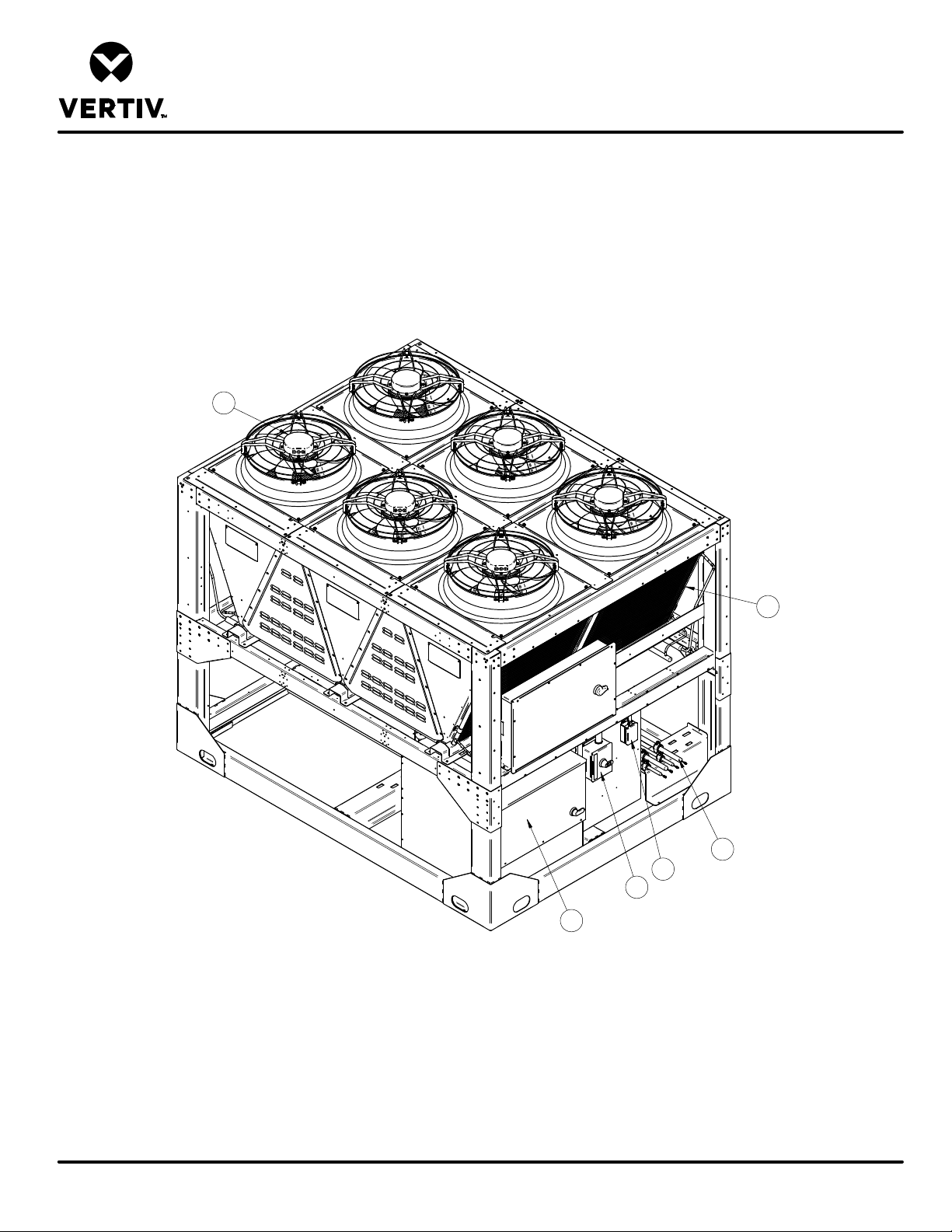
HEAT REJECTION SKID
COMPONENT LOCATION DIAGRAM
MCV330 + LIEBERT® ECONOPHASE + BASE ASSEMBLY
1. Coils
2. EC Fans
3. Liebert® Econophase Pump
4. High voltage customer connection
5. Low voltage customer connection
6. Piping connections
2
Note:
1. Piping connections for entire assembly are in one
location (item 6).
2. Electrical connections for entire assembly are located
in high voltage customer connection boxes (item 4)
and low voltage customer connection box (item 5).
1
6
5
4
3
Front
Form No.: DPN001040_REV4
DPN003888
Page :1 /1
REV : 2
REV DATE : 5/20
Page 68
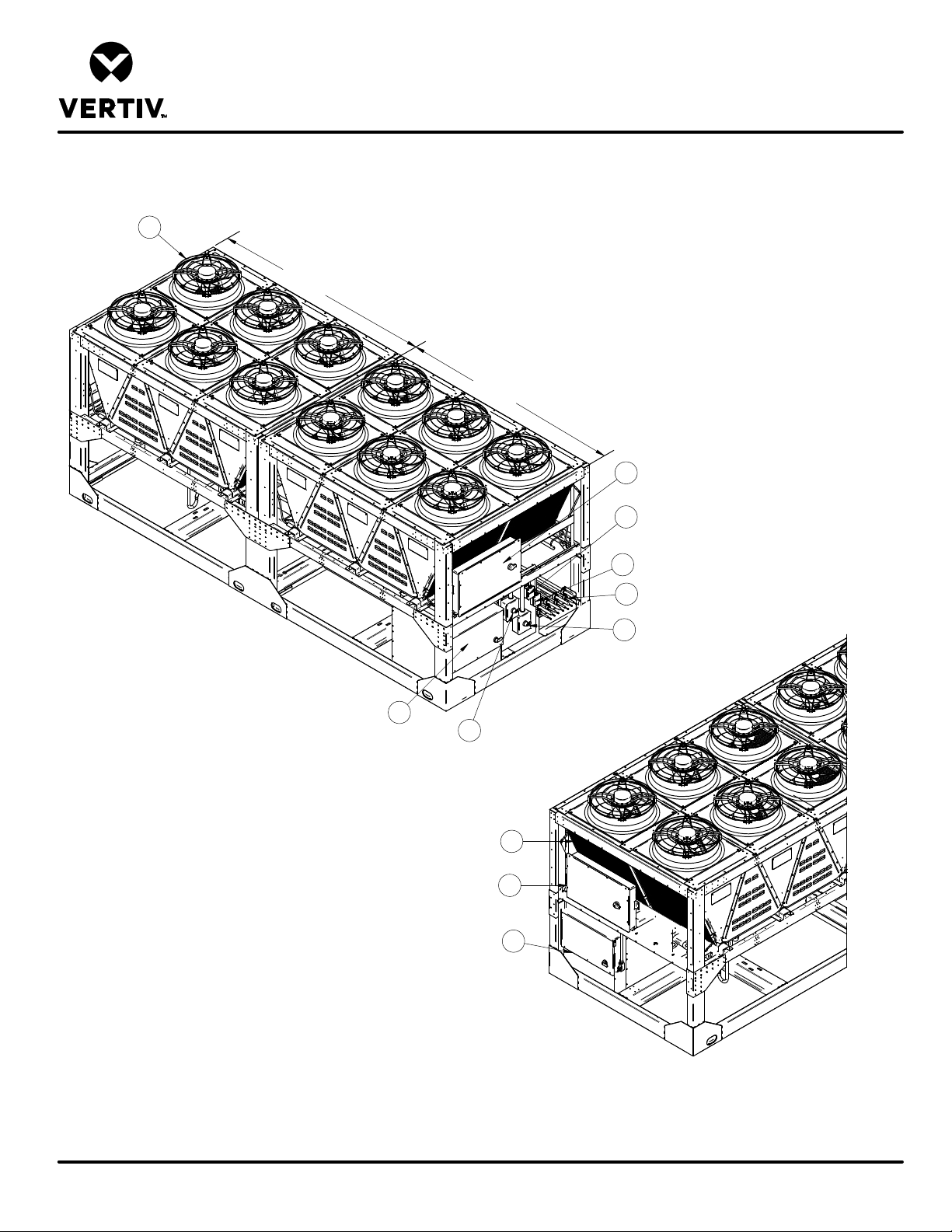
HEAT REJECTION SKID
COMPONENT LOCATION DIAGRAM
MCV330 (2) + LIEBERT® ECONOPHASE (2) + BASE ASSEMBLY
4
S
y
s
t
e
m
2
S
y
s
t
e
m
1
1. MCV330 Electric Panel System 1
2. MCV330 Electric Panel System 2
3. Coils
4. EC Fans
5. Liebert® ECONOPHASE- System 1
6. Liebert® ECONOPHASE- System 2
7. High voltage customer connection System 1
8. High voltage customer connection System 2
9. Low voltage customer connection System 1
10. Low voltage customer connection System 2
11. Piping connections Systems 1&2
1
9
10
11
8
Front
5
7
Form No.: DPN001040_REV4
DPN003872
Page :1 /1
Note:
1. Electrical connections for entire assembly are located
in high voltage customer connection boxes (items 7 & 8)
and low voltage customer connection box (item 9 & 10).
2. Piping connections for entire assembly are in one
location (item 11).
3
2
6
Back
REV : 2
REV DATE : 5/20
Page 69
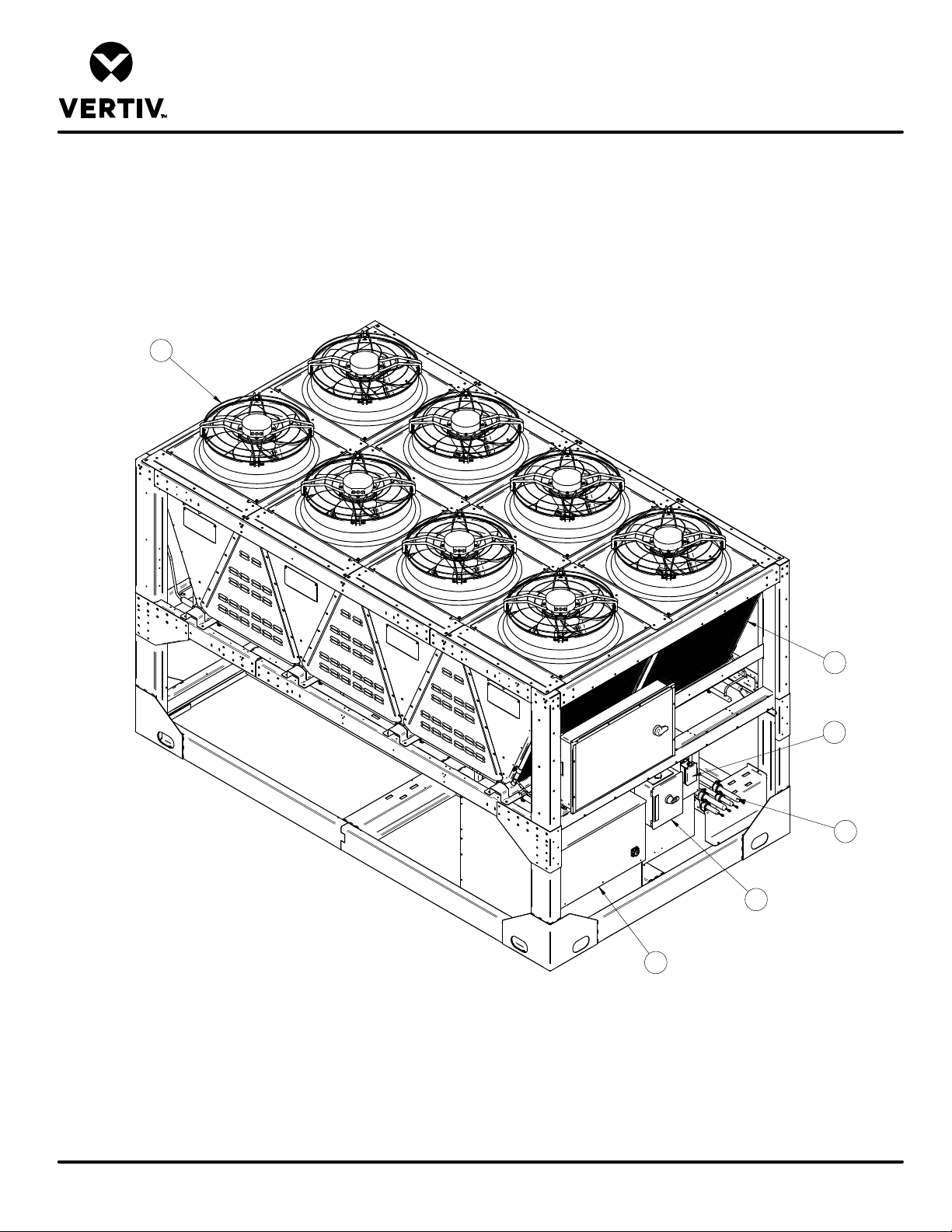
HEAT REJECTION SKID
COMPONENT LOCATION DIAGRAM
MCV440 + LIEBERT® ECONOPHASE + BASE ASSEMBLY
1. Coils
2. EC Fans
3. Liebert® Econophase Pump
2
4. High voltage customer connection
5. Low voltage customer connection
6. Piping connections
Note:
1. Piping connections for entire assembly are in one
location (item 6).
2. Electrical connections for entire assembly are located
in high voltage customer connection boxes (item 4)
and low voltage customer connection box (item 5).
1
5
6
4
Front
3
Form No.: DPN001040_REV4
DPN004258
Page :1 /1
REV : 2
REV DATE : 5/20
Page 70
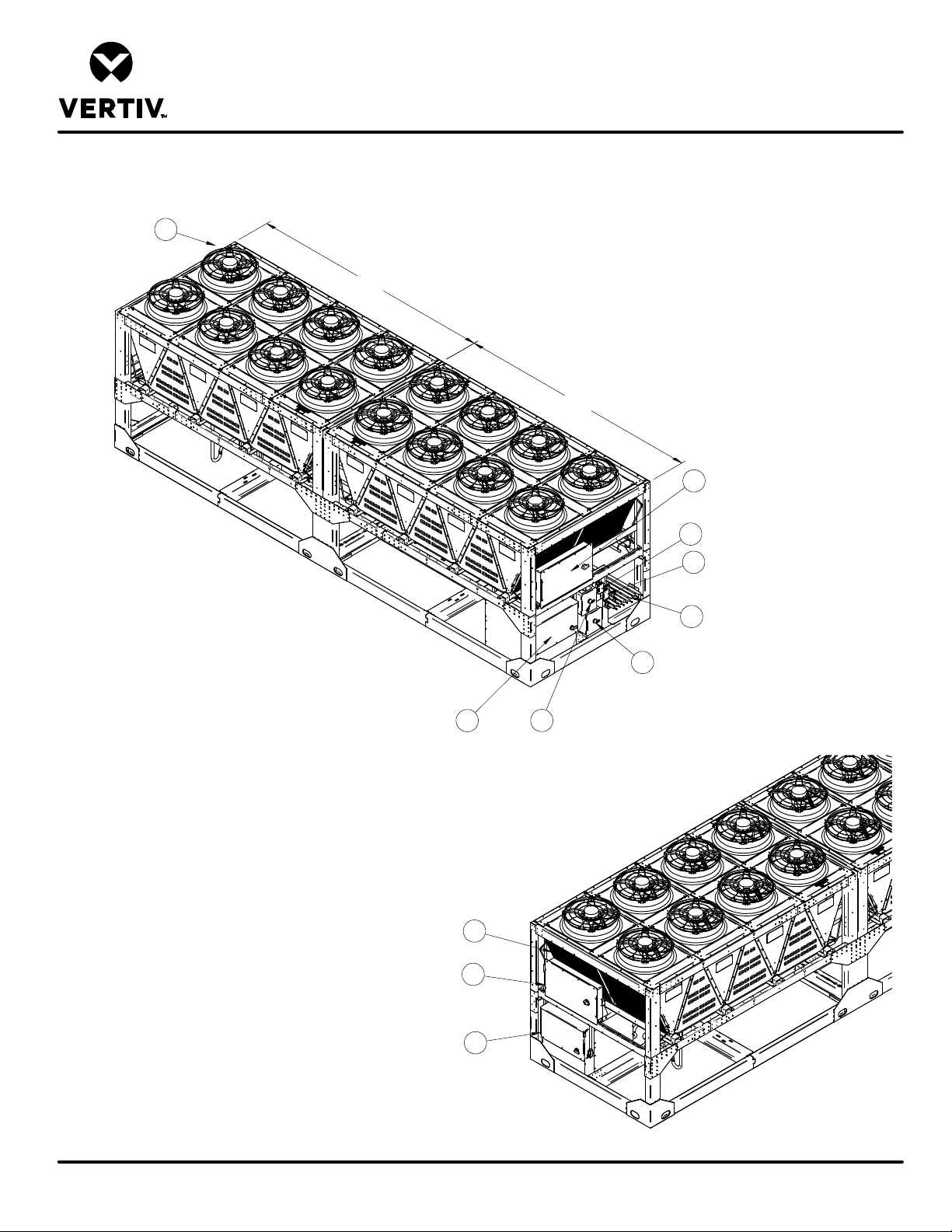
HEAT REJECTION SKID
COMPONENT LOCATION DIAGRAM
MCV440 (2) + LIEBERT® ECONOPHASE (2) + BASE ASSEMBLY
4
1. MCV440 Electric Panel System 1
System 2
System 1
2. MCV440 Electric Panel System 2
3. Coils
4. EC Fans
5. Liebert® ECONOPHASE- System 1
6. Liebert® ECONOPHASE- System 2
7. High voltage customer connection System 1
8. High voltage customer connection System 2
9. Low voltage customer connection System 1
10. Low voltage customer connection System 2
11. Piping connections Systems 1&2
1
9
Note:
1. Electrical connections for entire assembly are located
in high voltage customer connection boxes (items 7 & 8)
and low voltage customer connection box (item 9 & 10).
2. Piping connections for entire assembly are in one
location (item 11).
10
11
8
Front
5
3
2
7
Form No.: DPN001040_REV4
DPN004260
Page :1 /1
6
Rear
REV : 2
REV DATE : 5/20
Page 71
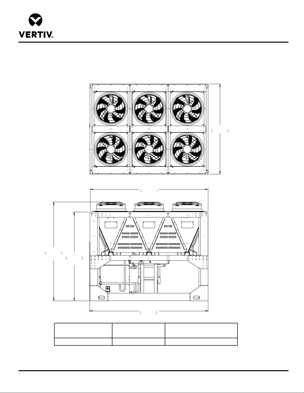
LIEBERT® HEAT REJECTION SKID
CABINET & ANCHOR DIMENSIONAL DATA
MCV330 + ECONOPHASE + BASE ASSEMBLY
101 1/4"
Main
Electrical
Box
End
2572mm
132"
3353mm
Cabinet
111"
2819mm
Overall
99 5/8"
2530mm
Cabinet
132 11/16"
3370mm
Overall
Model
MC V330 Single Skid 5000 (2268) 4980 (2258)
Shipping weight
lb (kg)
Dry w eight with a receiver and without
crating lb (kg)
Form No.: DPN001040_REV4
NOTES:
1) Minimum clearance on the Main Unit Disconnect Enclosure shall be 48" (1219mm) or per local code.
2) Recommended minimum 48" (1219mm) clearance when multiple skids are mounted side by side to ensure proper airflow. Contact the factory for other spacing requirements.
DPN003889
Page :1 /2
REV : 6
REV DATE : 2/20
Page 72
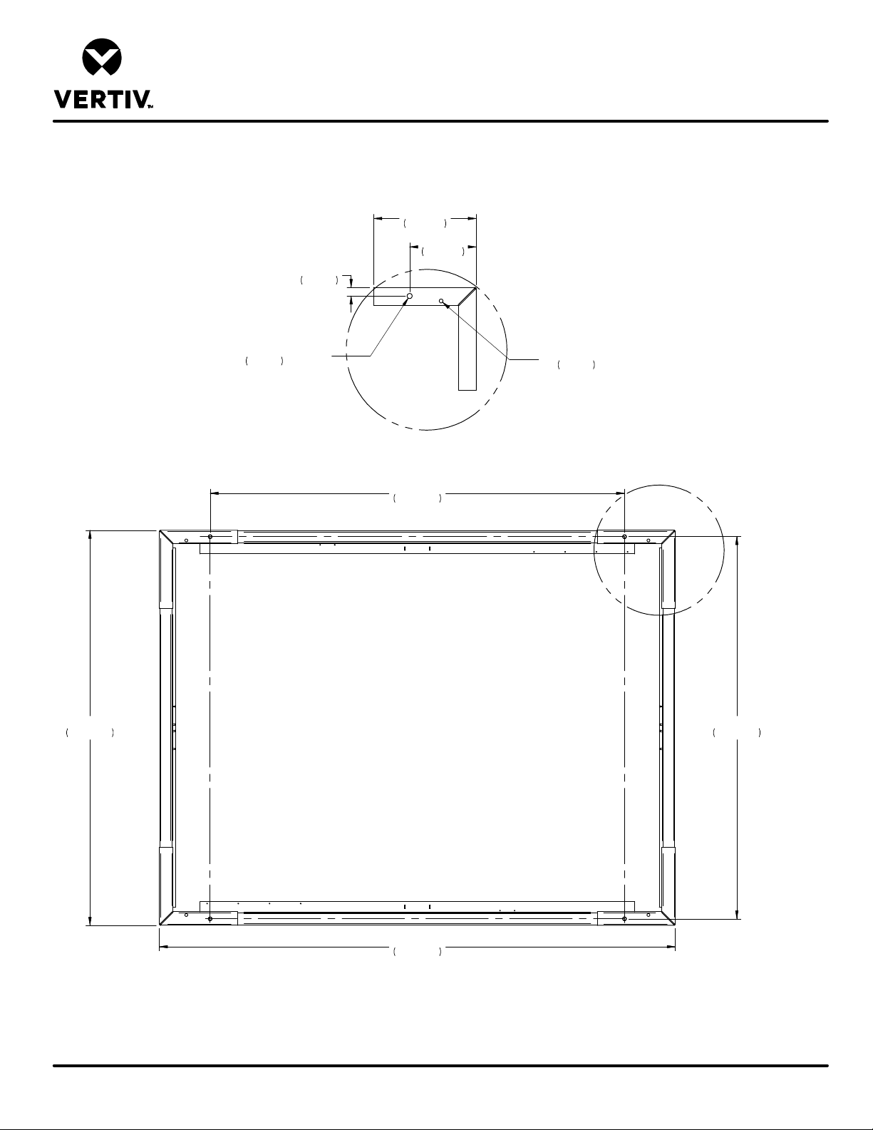
LIEBERT® HEAT REJECTION SKID
CABINET & ANCHOR DIMENSIONAL DATA
MCV330 + ECONOPHASE + BASE ASSEMBLY
20"
508mm
13"
330mm
1 5/8"
42mm
101 1/4"
2572mm
7/8"
O
22mm
(4) MOUNTING HOLES
(CONTACT POINTS)
DETAIL A
Typical (4) Places
106 1/4"
2699mm
3/4"
O
19mm
(4) WEEP HOLES
(REF)
A
98"
2488mm
Form No.: DPN001040_REV4
Main
Electrical
Box
End
132 1/4"
3360mm
NOTES:
1) Underside of unit, coil and fan removed for clarity.
2) Four mounting holes and four 3/4" field supplied bolts required to secure skid base assembly to customer support structure. Bolt grade to be specified by local requirements.
DPN003889
Page :2 /2
REV : 6
REV DATE : 2/20
Page 73
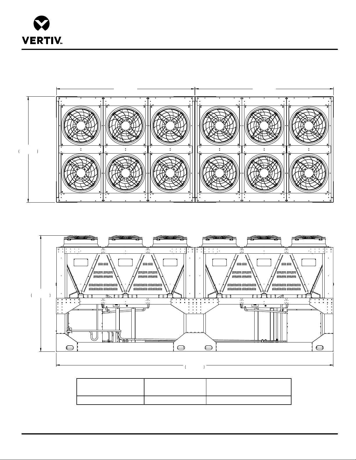
LIEBERT® HEAT REJECTION SKID
CABINET & ANCHOR DIMENSIONAL DATA
MCV330 (2) + ECONOPHASE(2) + BASE ASSEMBLY
Disconnect
101 1/4"
2572mm
Main
End
SYSTEM 1
SYSTEM 2
111"
2819mm
264 3/4"
6725mm
Model
MC V330 Dual Skid 10,000 (4,535) 9980 (4526)
Notes:
1. Minimum clearance of the Main Unit Disconnect Enclosure shall be 48" (1219mm) or per local electrical code.
2. Recommended minimum 48" (1219mm) clearance when multiple skids are mounted side by side to ensure proper airflow. Contact the factory for other spacing requirments.
DPN003875
Page :1 /2
Form No.: DPN001040_REV4
Shipping weight
lb (kg)
Dry weight with a receiver and without
crating lb (kg)
REV : 5
REV DATE : 2/20
Page 74
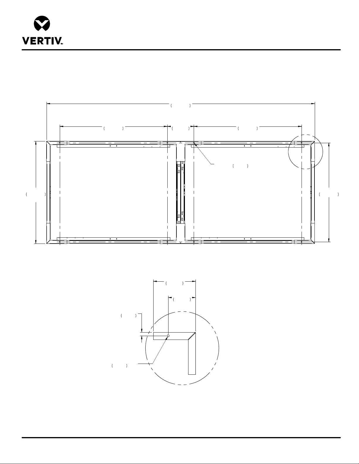
LIEBERT® HEAT REJECTION SKID
CABINET & ANCHOR DIMENSIONAL DATA
MCV330 (2) + ECONOPHASE(2) + BASE ASSEMBLY
264 3/4"
6725mm
101 1/4"
2572mm
TYP.
106 1/4"
2699mm
26 1/4"
667mm
Underside of unit, coil and fan removed for clarity.
20"
508mm
TYP.
13"
330mm
TYP.
1 5/8"
42mm
TYP.
106 1/4"
2699mm
7/8"
O
TYP.
(8) MOUNTING HOLES
22mm
(CONTACT POINTS)
A
97 15/16"
2488mm
Form No.: DPN001040_REV4
TYP.
(8) MOUNTING HOLES
22mm
7/8"
O
DETAIL A
Notes:
1. Eight mounting holes and eight 3/4" field supplied bolts required to secure skid base assembly to customer support structure. Bolt grade to be specified by local requirements.
DPN003875
Page :2 /2
REV : 5
REV DATE : 2/20
Page 75
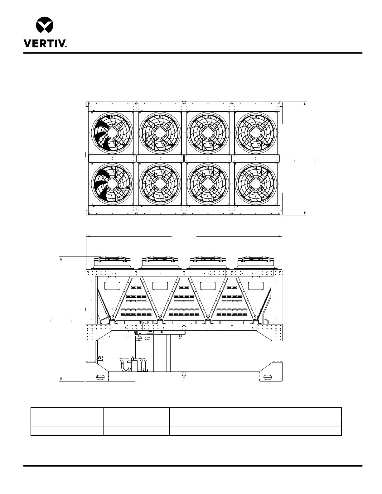
LIEBERT® HEAT REJECTION SKID
CABINET & ANCHOR DIMENSIONAL DATA
MCV440 + ECONOPHASE + BASE ASSEMBLY
Main
Electrical
Box
End
101 1/4"
2572mm
175"
4436mm
111"
2819mm
Model
MC V440 Single Skid 5900 (2676) 5880 (2667) 5780 (2621)
Shipping weight
lb (kg)
Dry weight with a receiver and without
crating lb (kg)
Dry weight without receiver and
crating lb (kg)
Form No.: DPN001040_REV4
NOTES:
1) Minimum clearance on the Main Unit Disconnect Enclosure shall be 48" (1219mm) or per local code.
2) Recommended minimum 48" (1219mm) clearance when multiple skids are mounted side by side to ensure proper airflow. Contact the factory for other spacing requirements.
DPN004259
Page :1 /2
REV : 3
REV DATE : 2/20
Page 76
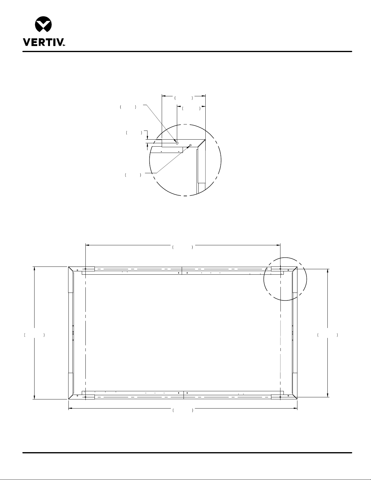
LIEBERT® HEAT REJECTION SKID
CABINET & ANCHOR DIMENSIONAL DATA
MCV440 + ECONOPHASE + BASE ASSEMBLY
20"
7/8"
O
22mm
(4) Mounting Holes
(Contact Points)
1 5/8"
42mm
3/4"
O
19mm
(4) Weep Holes
(REF)
508mm
13"
330mm
DETAIL A
Typ. (4) Places
101 1/4"
2572mm
Main
Electrical
Box
End
148 15/16"
3783mm
175"
4443mm
A
97 15/16"
2488mm
Form No.: DPN001040_REV4
NOTES:
1) Underside of unit, coil and fan removed for clarity.
2) Four mounting holes and four 3/4" field supplied bolts required to secure skid base assembly to customer support structure. Bolt grade to be specified by local requirements.
DPN004259
Page :2 /2
REV : 3
REV DATE : 2/20
Page 77
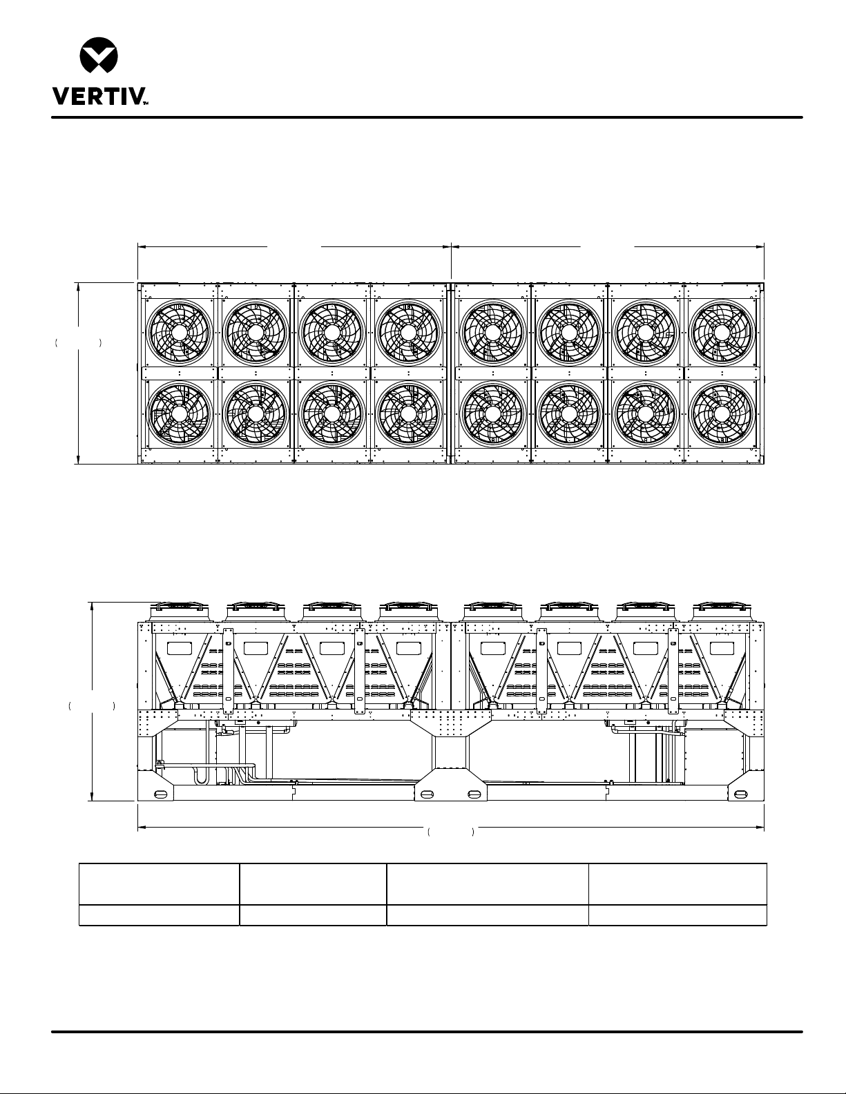
101 1/4"
2572mm
LIEBERT® HEAT REJECTION SKID
CABINET & ANCHOR DIMENSIONAL DATA
MCV440 (2) + ECONOPHASE (2) + BASE ASSEMBLY
System 1 System 2
Main
Electrical
Box
End
111"
2819mm
350"
8892mm
Model
MC V440 Dual Skid 11,580 (5252) 11560 (5243) 11360 ( 5152)
Notes:
1. Minimum clearance of the Main Unit Disconnect Enclosure shall be 48" (1219mm) or per local electrical code.
2. Recommended minimum 48" (1219mm) clearance when multiple skids are mounted side by side to ensure proper airflow. Contact the factory for other spacing requirments.
DPN004261
Page :1 /2
Form No.: DPN001040_REV4
Shipping weight
lb (kg)
Dry weight with a receiver and without
crating lb (kg)
Dry weight without receiver and
crating lb (kg)
REV : 4
REV DATE : 2/20
Page 78
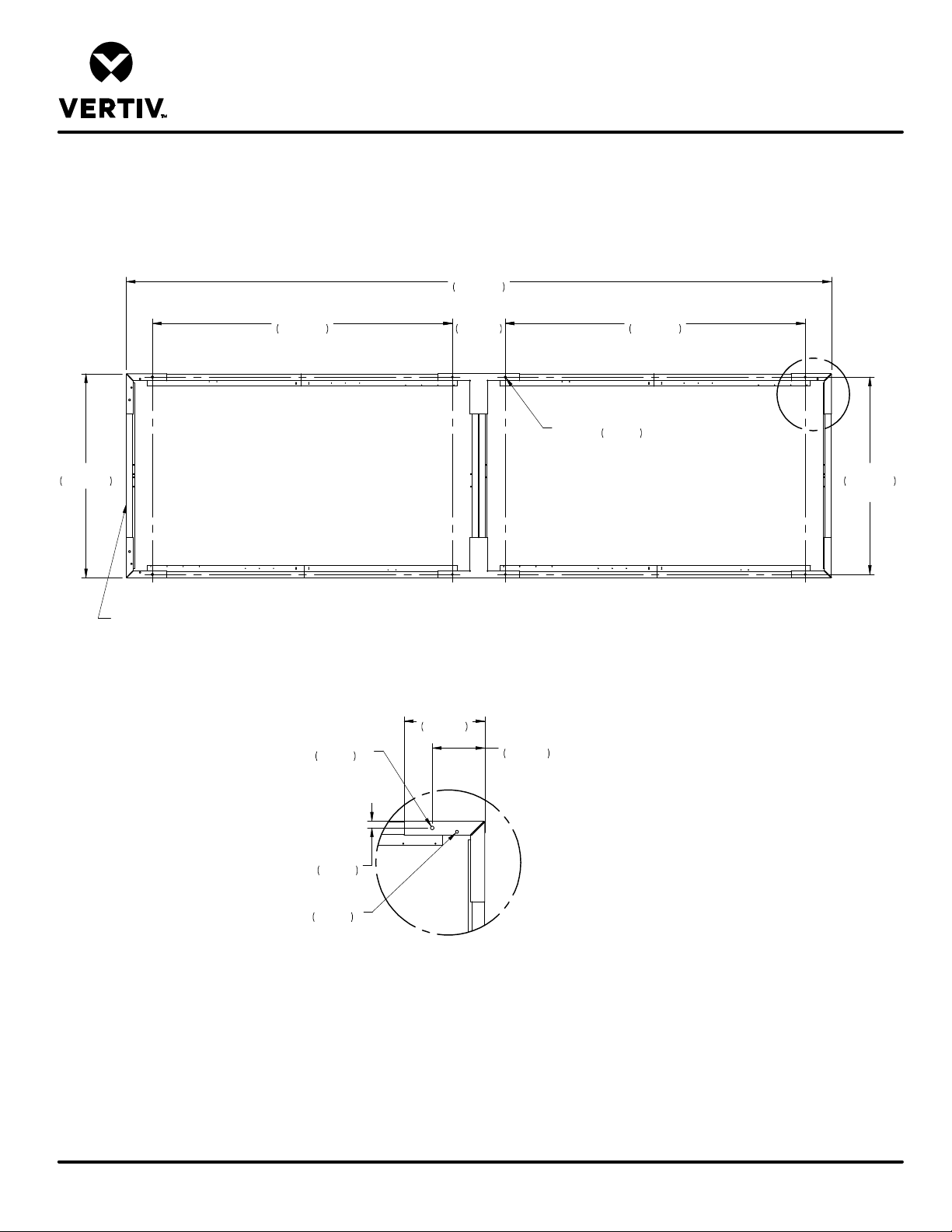
LIEBERT® HEAT REJECTION SKID
CABINET & ANCHOR DIMENSIONAL DATA
MCV440 (2) + ECONOPHASE (2) + BASE ASSEMBLY
350"
8892mm
101 1/4"
2572mm
Main Electrical
Box End
148 7/8"
3782mm
7/8"
O
22mm
(8) Mounting Holes
26 1/4"
667mm
TYP.
(8)Mounting Holes
Contact Points)
Underside of Unit
Coil and Fans removed for clarity
20"
508mm
13"
331mm
148 7/8"
3782mm
A
7/8"
O
22mm
97 15/16"
2488mm
Typ.
Form No.: DPN001040_REV4
1 5/8"
41mm
3/4"
O
19mm
(4) Weep Holes
(REF)
DETAIL A
Typical (4) Places
Notes:
1. Eight mounting holes and eight 3/4" field supplied bolts required to secure skid base assembly to customer support structure. Bolt grade to be specified by local requirements.
DPN004261
Page :2 /2
REV : 4
REV DATE : 2/20
Page 79
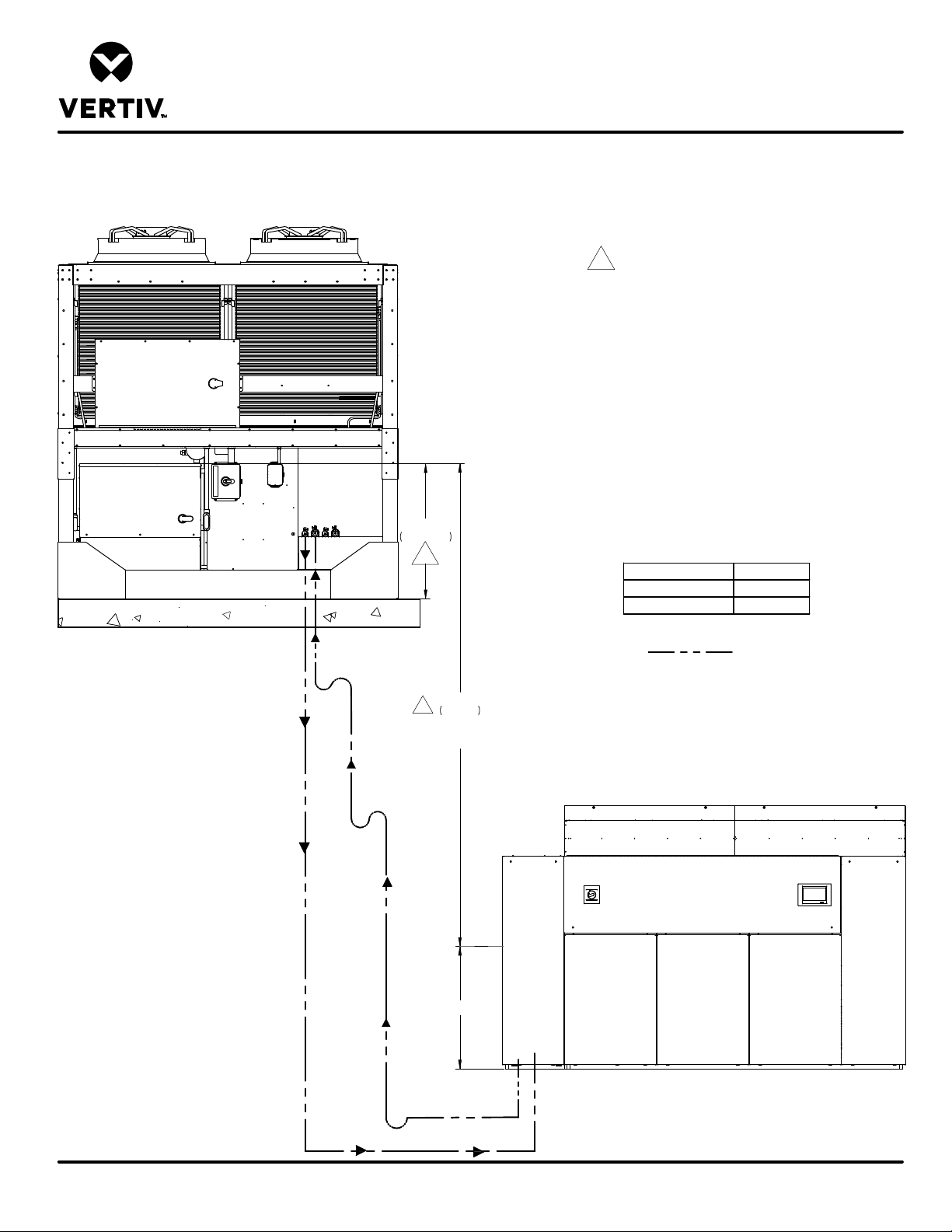
LIEBERT® DSE
Notes:
he vertical
Unit piping entrance varies by unit and may be through
insulated, ½ inch minimum. All outdoor insulation must
Notes:
Liebert
MCV Condenser
Liebert
EconoPhase
Liebert
DSE
AIR COOLED PIPING SCHEMATIC
LIEBERT® MCV MOUNTED ABOVE LIEBERT® DA125-150
CIRCUIT 1
®
®
Unit
Unit
CIRCUIT 2
Liquid
Return
Hot Gas
Discharge
44 1/2inch
1130mm
1
60ft
1
18.3m
Maximum Vertical
Rise
1. The outlet of the receiver must be higher than the
elevation of the EEV inside the indoor unit. T
height must not be greater than 60 ft (18.3 m).
2. Unit must be trapped at bottom of riser with any rise
over 5 feet (1.5m) high. If rise exceeds 25 feet (7.5m),
then a trap is required in 20 foot (6.1m) increments or
evenly divided. DA250 with horizontal discharge has
internally installed traps on the hot gas discharge line.
3. Pitch horizontal hot gas piping at a minimum of
½ inch per 10 feet (42mm per 10m) so that gravity will
aid in moving oil in the direction of the refrigeration
flow.
4.
the top of the unit.
5. All indoor and outdoor field refrigerant piping must be
be UV and ozone resistant.
6. Consult factory for any exceptions to the above
guidelines.
Internal EEV Height H inch ( mm)
DA125-DA165 43 (1092)
DA250 56 (1422)
Field Piping
DPN003965
Page :1 /2
Form No.: DPN001040_REV4
Liquid
Return
Liquid
Return
Hot Gas
Discharge
H
Hot Gas
Discharge
Liquid
Return
®
DA250 with horizontal discharge should be piped out
the top of unit.
REV : 5
REV DATE : 5/20
Page 80
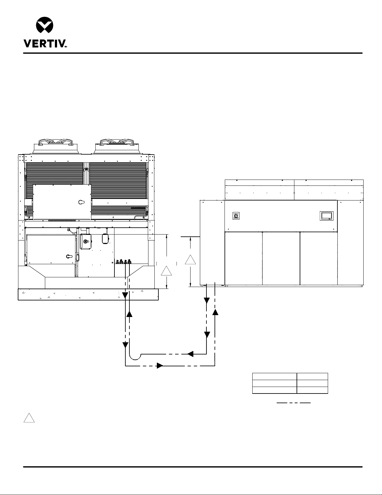
LIEBERT® DSE
Notes:
Notes:
Liebert
MCV Condenser
Liebert
EconoPhase
Liebert
DSE
AIR COOLED PIPING SCHEMATIC
LIEBERT® MCV AND LIEBERT® DA125-150 AT SIMILAR LEVELS
CIRCUIT 1
®
®
Unit
Unit
CIRCUIT 2
44 1/2inch
1130mm
1
®
H
1
DA250 with horizontal discharge should be piped out
the top of unit.
DPN003965
Page :2 /2
Form No.: DPN001040_REV4
Hot Gas
Hot Gas
Liquid
Return
1. The outlet of the receiver must be higher than the elevation of the EEV inside the indoor unit.
2. Unit must be trapped at bottom of riser with any rise over 5 feet (1.5m) high. If rise exceeds 25 feet (7.5m), then a trap is required in 20 foot
(6.1m) increments or evenly divided. DA250 with horizontal discharge has internally installed traps on the hot gas discharge line.
3. Pitch horizontal hot gas piping at a minimum of ½ inch per 10 feet (42mm per 10m) so that gravity will aid in moving oil in the direction of the
refrigeration flow.
4. Unit piping entrance varies by unit and may be through the top of the unit.
5. All indoor and outdoor field refrigerant piping must be insulated, ½ inch minimum. All outdoor insulation must be UV and ozone resistant.
6. Consult factory for any exceptions to the above guidelines.
Discharge
Hot Gas Discharge
Discharge
Liquid
Return
Liquid
Return
Internal EEV Height H inch ( mm)
DA125-DA165 43 (1092)
DA250 56 (1422)
Field Piping
REV : 5
REV DATE : 5/20
Page 81
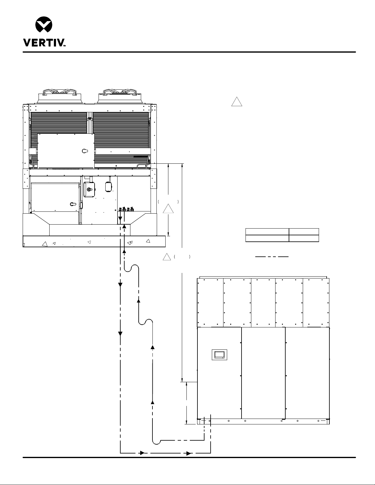
CIRCUIT 1
Notes:
Unit piping entrance varies by unit and may be through
Notes:
Liebert
MCV Condenser
Liebert
EconoPhase
®
®
Unit
Unit
LIEBERT® DSE
AIR COOLED PIPING SCHEMATIC
Liebert® MCV MOUNTED ABOVE DA265
CIRCUIT 2
1. The bottom of the condenser coil must be no greater
than 60 ft (18.3m) higher than the elevation of the EEV
inside the indoor unit.
2. Unit must be trapped at bottom of riser with any rise
over 5 feet (1.5m) high. If rise exceeds 25 feet (7.5m),
then a trap is required in 20 foot (6.1m) increments or
evenly divided. DA265 with horizontal discharge has
internally installed traps on the hot gas discharge line.
3. Pitch horizontal hot gas piping at a minimum of
½ inch per 10 feet (42mm per 10m) so that gravity will
aid in moving oil in the direction of the refrigeration
flow.
4.
the top of the unit.
5. All indoor and outdoor field refrigerant piping must be
54 7/8"
1393mm
1
insulated, ½ inch minimum. All outdoor insulation must
be UV and ozone resistant.
6. Consult factory for any exceptions to the above
guidelines.
Liquid
Return
Liquid
Return
Hot Gas
Discharge
Hot Gas
Discharge
60ft
18.3m
1
Maximum Vertical
Rise
H
Internal EEV Height H inch ( mm)
DA265 56 (1422)
Field Piping
DPN005207
Page :1 /2
Form No.: DPN001040_REV4
Liquid
Return
Hot Gas
Discharge
Liquid
Return
DA265 with horizontal discharge should be piped out
the top of unit.
REV : 0
REV DATE : 2/20
Page 82
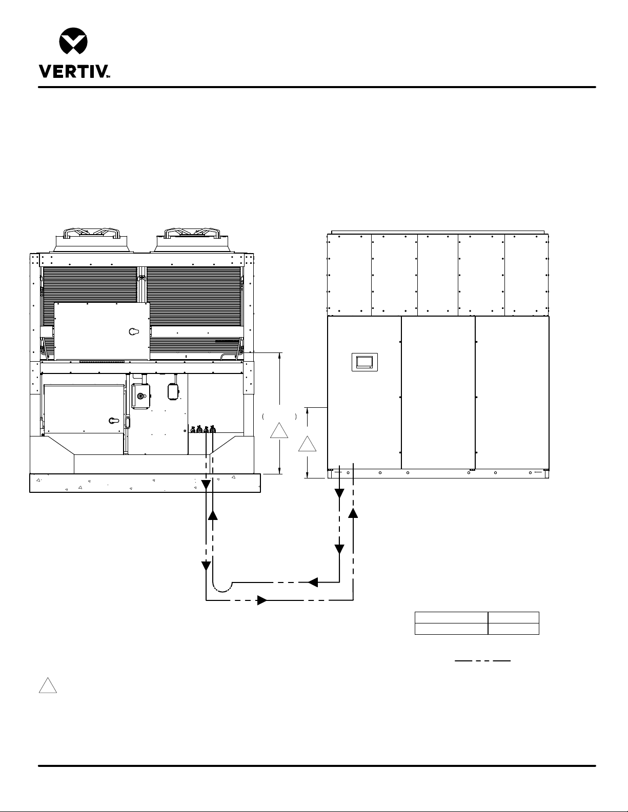
LIEBERT® DSE
Notes:
Notes:
Liebert
MCV Condenser
Liebert
EconoPhase
AIR COOLED PIPING SCHEMATIC
Liebert® MCV AND DA265 AT SIMILAR LEVEL
CIRCUIT 1
®
®
Unit
Unit
CIRCUIT 2
Liquid
Return
Hot Gas
Discharge
Hot Gas Discharge
54 7/8"
1393mm
1
H
1
Hot Gas
Discharge
DA265 with horizontal discharge should be piped out
the top of unit.
Liquid
Return
DPN005207
Page :2 /2
Form No.: DPN001040_REV4
Liquid
Return
1. The bottom of the condenser coil must be less than 15ft(4.6m) below the elevation of the EEV inside the indoor unit.
2. Unit must be trapped at bottom of riser with any rise over 5 feet (1.5m) high. If rise exceeds 25 feet (7.5m), then a trap is required in 20 foot
(6.1m) increments or evenly divided. DA265 with horizontal discharge has internally installed traps on the hot gas discharge line.
3. Pitch horizontal hot gas piping at a minimum of ½ inch per 10 feet (42mm per 10m) so that gravity will aid in moving oil in the direction of the
refrigeration flow.
4. Unit piping entrance varies by unit and may be through the top of the unit.
5. All indoor and outdoor field refrigerant piping must be insulated, ½ inch minimum. All outdoor insulation must be UV and ozone resistant.
6. Consult factory for any exceptions to the above guidelines.
Internal EEV Height H inch ( mm)
DA265 56 (1422)
Field Piping
REV : 0
REV DATE : 2/20
Page 83
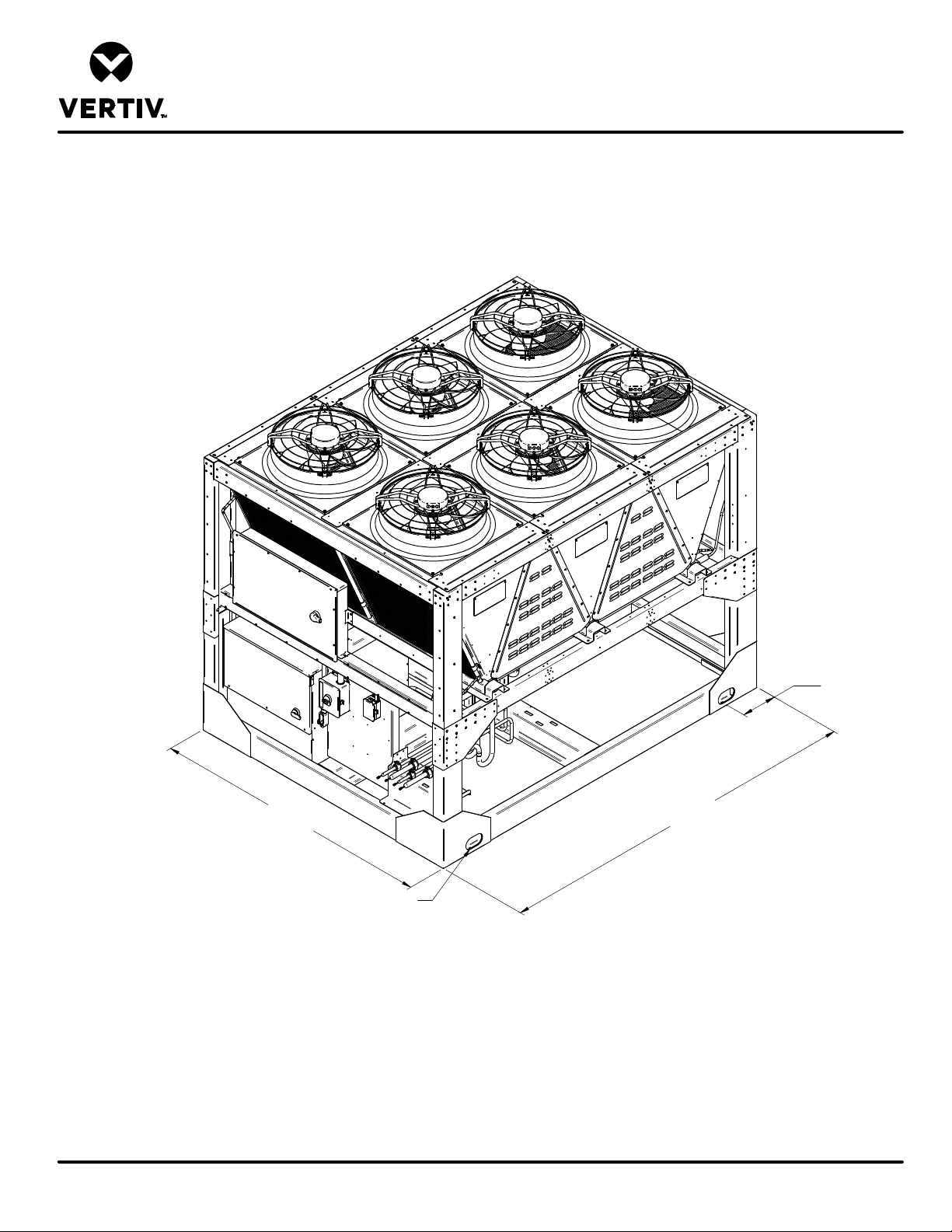
LIEBERT® HEAT REJECTION SKID
CABINET LIFTING POINTS
MCV330 + ECONOPHASE + BASE ASSEMBLY
101 1/4"
2570mm
4" X 7"
(102mm X 178mm)
Lifting Points
Typ. (4) Places
Note:
1. Use indicated lifting points to lift the unit. Use spreader bars and/or shimmed blocks to prevent external damage.
2. Sections must be lifted level. Tilting can cause damage to the equipment inside.
3. Use proper rigging equipment to make sure attachment and lifting at the designated lift points is in the vertical direction.
-Refer to User Manual for site instructions.
132 1/4"
3358mm
13"
330mm
TYP.
Form No.: DPN001040_REV4
DPN003882
Page :1 /1
REV : 3
REV DATE : 2/20
Page 84
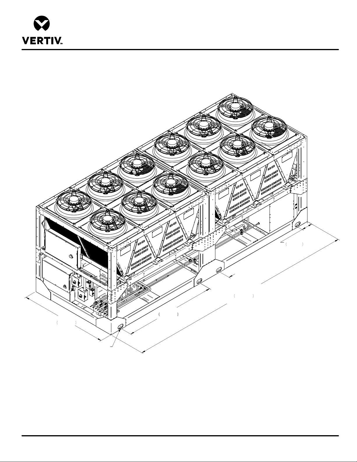
LIEBERT® HEAT REJECTION SKID
CABINET LIFTING POINTS
MCV330 (2) + ECONOPHASE (2) + BASE ASSEMBLY
26 1/4"
667mm
101 1/4"
2572mm
106 1/4"
2699mm
TYP.
TYP.
264 3/4"
6723mm
Front
4" X 7"
(102mm X 178mm)
Lifting Points
Typ. (8) Places
Note:
1. Use indicated lifting points to lift the unit. Use spreader bars and/or shimmed blocks to prevent external damage.
2. Unit must be lifted level. Tilting or twisting can cause damage to internal components.
3. Use proper rigging equipment to make sure attachment and lifting at the designated lift points is in the vertical direction.
-Refer to User Manual for site instructions.
13"
330mm
TYP.
Form No.: DPN001040_REV4
DPN003883
Page :1 /1
REV : 3
REV DATE : 2/20
Page 85
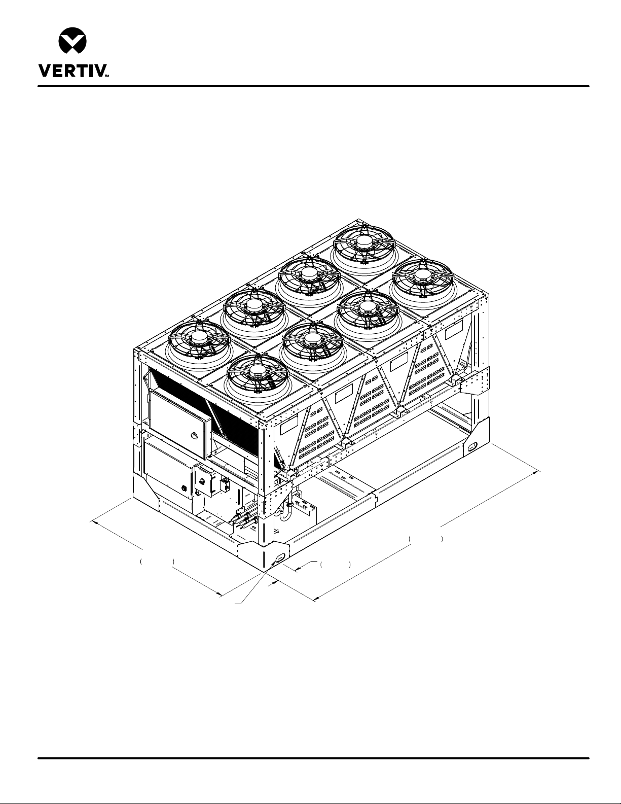
LIEBERT® HEAT REJECTION SKID
CABINET LIFTING POINTS
MCV440 + ECONOPHASE + BASE ASSEMBLY
Form No.: DPN001040_REV4
DPN004256
Page :1 /1
175"
4443mm
101 1/4"
2572mm
4" X 7"
(102mm X 178mm)
Lifting Points
Typ. (4) Places
Notes:
1. Use indicated lifting points to lift the unit. Use spreader bars and/or shimmed blocks to prevent external damage.
2. Unit must be lifted level. Tilting can cause damage to the equipment inside.
3. Use proper rigging equipment to make sure attachment and lifting at the designated lift points is in the vertical direction.
-Refer to User Manual for site intructions.
13"
330mm
Typ.
REV : 2
REV DATE : 2/20
Page 86
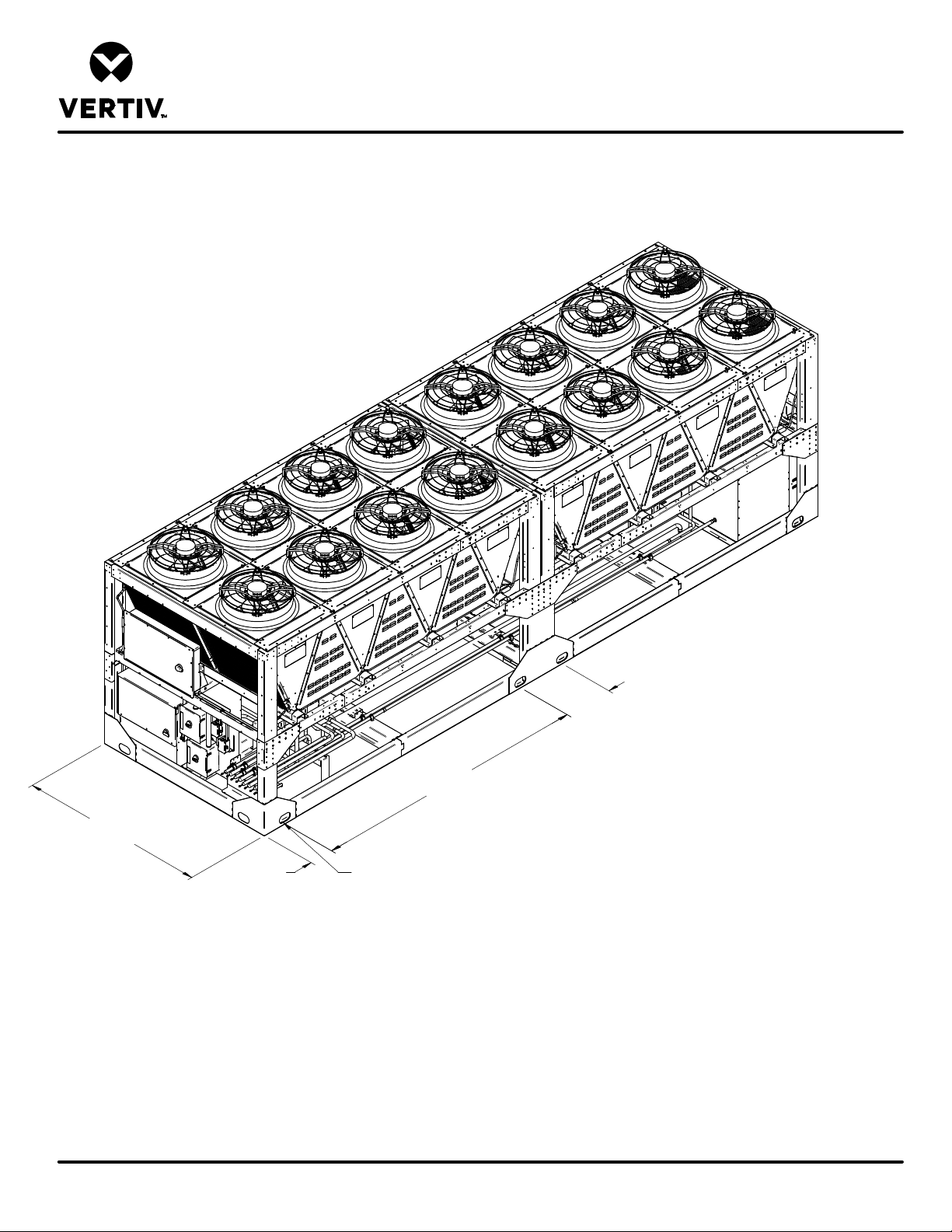
LIEBERT® HEAT REJECTION SKID
CABINET LIFTING POINTS
MCV440 (2) + ECONOPHASE (2) + BASE ASSEMBLY
101 1/4"
2572mm
26 1/4"
667mm
Typ.
148 7/8"
3781mm
Front
13"
330mm
Typ.
Note:
1. Use indicated lifting points to lift the unit. Use spreader bars and/or shimmed blocks to prevent external damage.
2. Unit must be lifted level. Tilting or twisting can cause damage to internal components.
3. Use proper rigging equipment to make sure attachment and lifting at the designated lift points is in the vertical direction.
-Refer to User Manual for site instructions.
4" X 7"
(102mm X 178mm)
Lifting Points
Typ. (8) Places
Typ.
Form No.: DPN001040_REV4
DPN004263
Page :1 /1
REV : 2
REV DATE : 2/20
Page 87
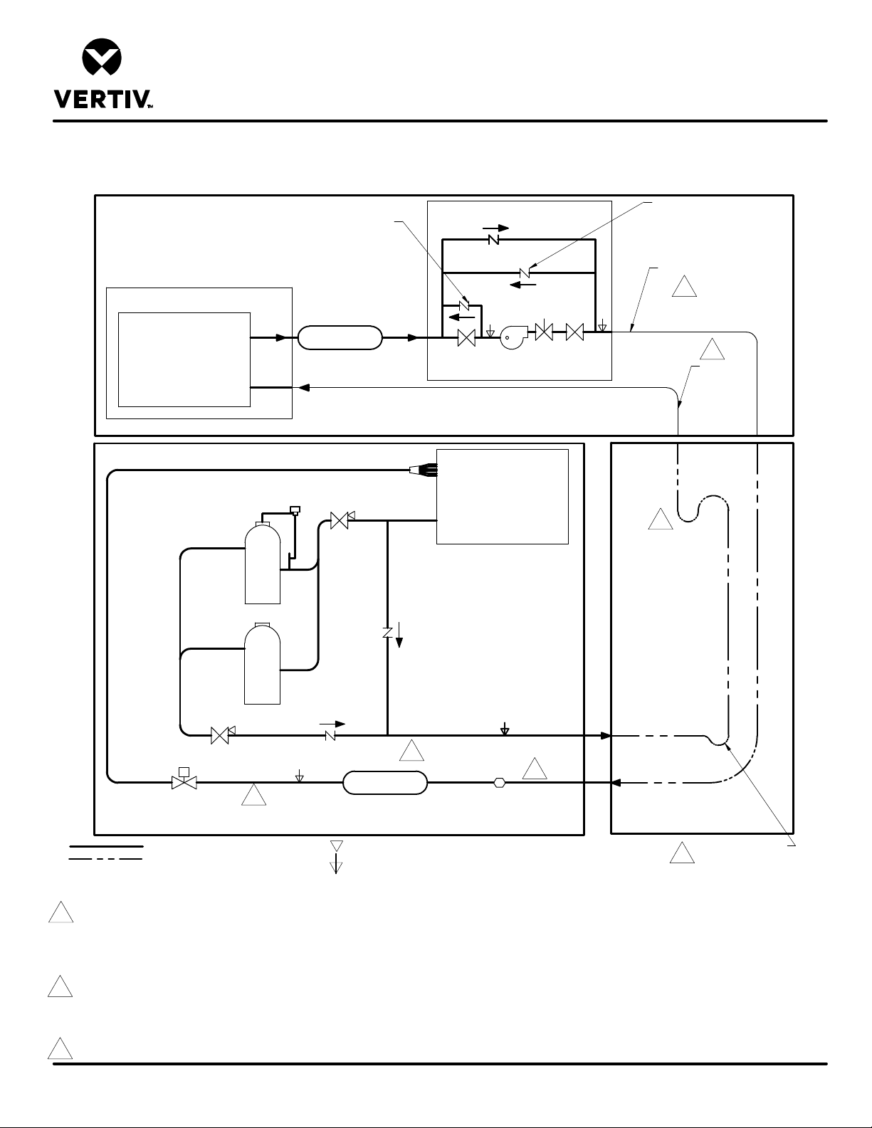
DA125, DA150, DA165 & DA250 with LIEBERT MCV
LIEBERT MCV HEAT REJECTION SKID
LIEBERT MCV CONDENSER
LIEBERT DSE
PIPING SCHEMATIC
Differential
Check Valve
LIEBERT DSE
RECEIVER
Optional "EconoPhase" UNIT
Check
Valve
Differential
Check Valve
Liquid to Indoor Unit
2
Solenoid
Valve
9
Ball Valve
6
For rises over
25ft. (7.6m), trap
every 20ft. (6m)
or evenly divided*
INTERCONNECTING
PIPING
LIEBERT DSE
Electronic
Expansion
Valve
Service
Valve
LIQUID RETURN
2
Service
Valve
Check
Valve
LIQUID
Check
Valve
Filter Drier
Ball Valve
SUCTION
HOT GAS DISCHARGE
2
EVAPORATOR
COIL
Sight Glass
FACTORY REFRIGERANT PIPING
FIELD PIPING
Notes:
1. Two refrigeration circuits provided. Single refrigeration circuit shown for clarity.
2. Circuit 1 must be maintained between indoor unit, condenser and EconoPhase unit. Circuit 2 must be maintained between indoor unit, condenser and EconoPhase unit.
3. Schematic representation shown. Do not use for specific connection locations.
4. The outlet of the receiver must be higher than the elevation of the EEV inside the indoor unit. This vertical height must not exceed 60ft. (18.3m). Liebert DSE Receiver required
for systems with or without EconoPhase unit.
5. All indoor and outdoor field refrigerant piping must be insulated, 1/2" minimum thickness. All outdoor insulation must be UV and ozone resistant.
6. Components are not supplied by Liebert but are required for proper circuit operation and maintenance (DA250 with top piping has internally installed traps on the discharge lines).
7. Traps must be installed and horizontal lines pitched to ensure proper oil return and to reduce liquid flood back to compressor. Pitch horizontal gas piping at a minimum of
1/2" per 10 feet (42mm per 10m) so that gravity will aid in moving oil in the direction of the refrigeration flow.
8. Do not isolate any refrigeration circuits from over pressurization protection.
SERVICE/SCHRADER (ACCESS) CONNECTION, NO VALVE CORE.
SERVICE/SCHRADER (ACCESS) CONNECTION, WITH VALVE CORE.
2
Hot Gas
Discharge
from Indoor
Unit
Trap at base of risers
6
over 5ft. (1.5m)*
Form No.: DPN001040_REV4
9. Typical location for Sight Glass on DA150 and DA165. On DA125, Sight Glass is located between Filter Drier and Electronic Expansion Valve.
DPN004476
Page :1 /1
REV : 2
REV DATE : 9/19
Page 88
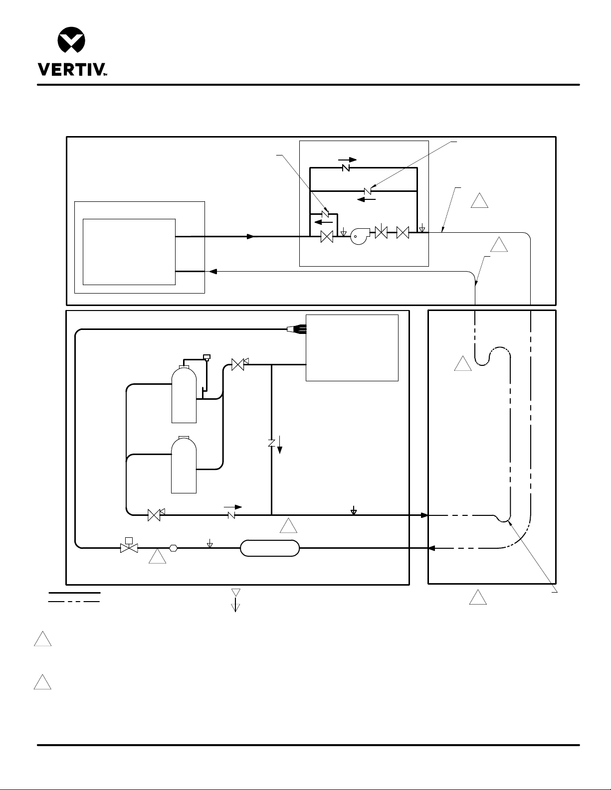
LIEBERT® DSE
DA265 with LIEBERT
MCV
Liebert
MCV HEAT REJECTION SKID
Optional
Liebert
EconoPhase" UNIT
Liebert
MCV CONDENSER
Liebert
DSE
PIPING SCHEMATIC
®
®
®
®
Differential
Check Valve
Service
Valve
Ball Valve
LIQUID
SUCTION
®
Check
Valve
Solenoid
Valve
EVAPORATOR
COIL
Ball Valve
Differential
Check Valve
Liquid to Indoor Unit
2
2
Hot Gas
Discharge
from Indoor
Unit
6
For rises over
25ft. (7.6m), trap
every 20ft. (6m)
or evenly divided*
Check
Valve
Service
Valve
Check
Valve
Filter Drier
Electronic
Expansion
Valve
Sight Glass
LIQUID RETURN
2
FACTORY REFRIGERANT PIPING
FIELD PIPING
Notes:
1. Two refrigeration circuits provided. Single refrigeration circuit shown for clarity.
2. Circuit 1 must be maintained between indoor unit, condenser and EconoPhase unit. Circuit 2 must be maintained between indoor unit, condenser and Liebert EconoPhase unit.
3. Schematic representation shown. Do not use for specific connection locations.
4. The bottom of the condenser coil must be no greater than 60 ft (18.3m) above and less than 15 ft (4.6m) below the elevation of the EEV inside the indoor unit.
5. All indoor and outdoor field refrigerant piping must be insulated, 1/2" minimum thickness. All outdoor insulation must be UV and ozone resistant.
6. Components are not supplied by Liebert but are required for proper circuit operation and maintenance (DA265 with top piping has internally installed traps on the discharge lines).
7. Traps must be installed and horizontal lines pitched to ensure proper oil return and to reduce liquid flood back to compressor. Pitch horizontal gas piping at a minimum of
1/2" per 10 feet (42mm per 10m) so that gravity will aid in moving oil in the direction of the refrigeration flow.
8. Do not isolate any refrigeration circuits from over pressurization protection.
SERVICE/SCHRADER (ACCESS) CONNECTION, NO VALVE CORE.
SERVICE/SCHRADER (ACCESS) CONNECTION, WITH VALVE CORE.
HOT GAS DISCHARGE
2
INTERCONNECTING
PIPING
Trap at base of risers
6
over 5ft. (1.5m)*
®
DPN005206
Page :1 /1
Form No.: DPN001040_REV4
REV : 0
REV DATE : 2/20
Page 89
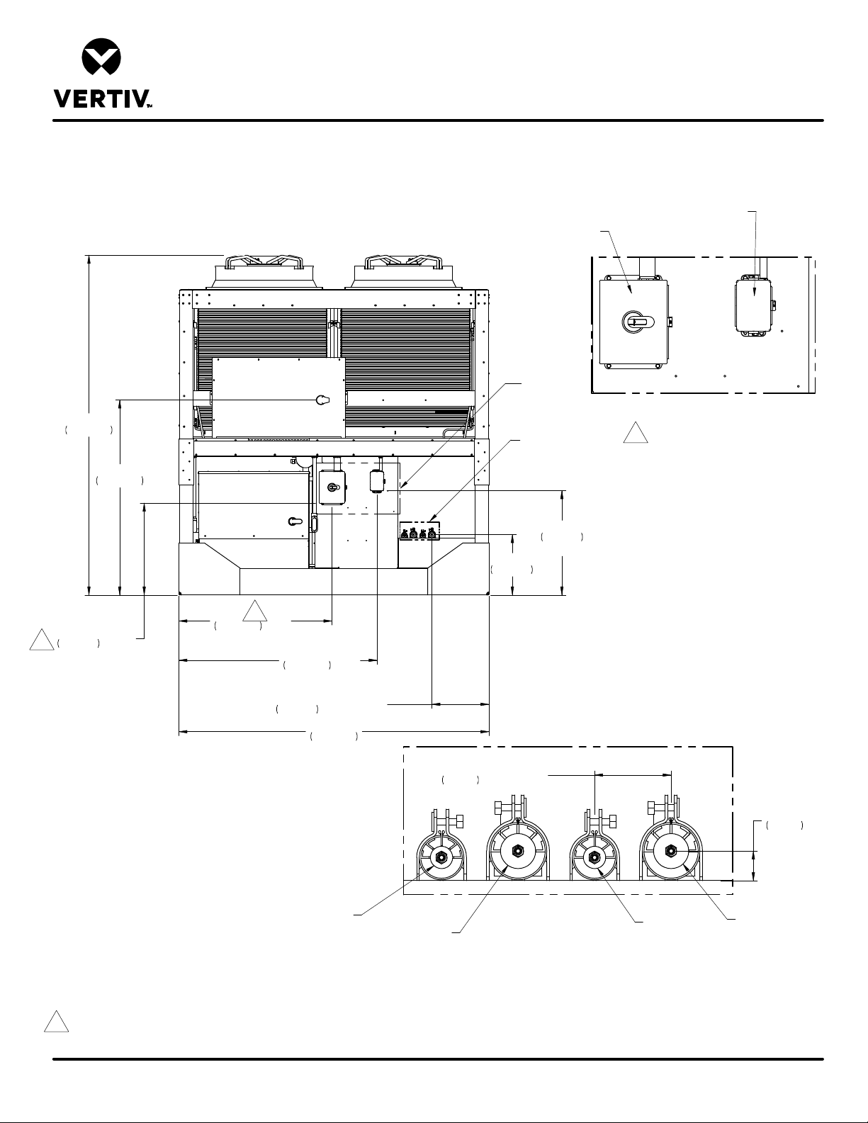
LIEBERT® HEAT REJECTION SKID
PRIMARY CONNECTION LOCATIONS
MCV330 + ECONOPHASE + BASE ASSY 460V & 575V
LOW VOLTAGE CUSTOMER
CIRCUIT 1
CIRCUIT 2
HIGH VOLTAGE CUSTOMER
CONNECTION
B
CONNECTION
111"
2819mm
30"
2
762mm
BOTTOM OF BOX
63 11/16"
1617mm
2
50"
1269mm
CENTER OF BOX
Front View
64 11/16"
1644mm
CENTER OF BOX
18 5/8"
473mm
u 1/2" (13mm)
101 1/4"
2572mm
3"
76mm
TYP.
A
19 11/16"
501mm
u 1/2" (13mm)
34"
864mm
BOTTOM OF BOX
DETAIL B
(Field Electrical Connections)
2
1 3/16"
29mm
7/8" LIQUID LINE
CIRCUIT 1
Notes:
1. Field to provide hole for conduit for high voltage disconnect box and low voltage distribution panel.
2. High Voltage Customer Connection for:
Voltage Codes: A=(460V/3 Phase/60Hz); B=(575V/3 Phase/60Hz)
DPN003887
Page :1 /1
Form No.: DPN001040_REV4
1 3/8" HOT GAS
CIRCUIT 1
DETAIL A
(PIPING CONNECTIONS)
7/8" LIQUID LINE
CIRCUIT 2
1 3/8" HOT GAS
CIRCUIT 2
REV : 5
REV DATE : 2/20
Page 90
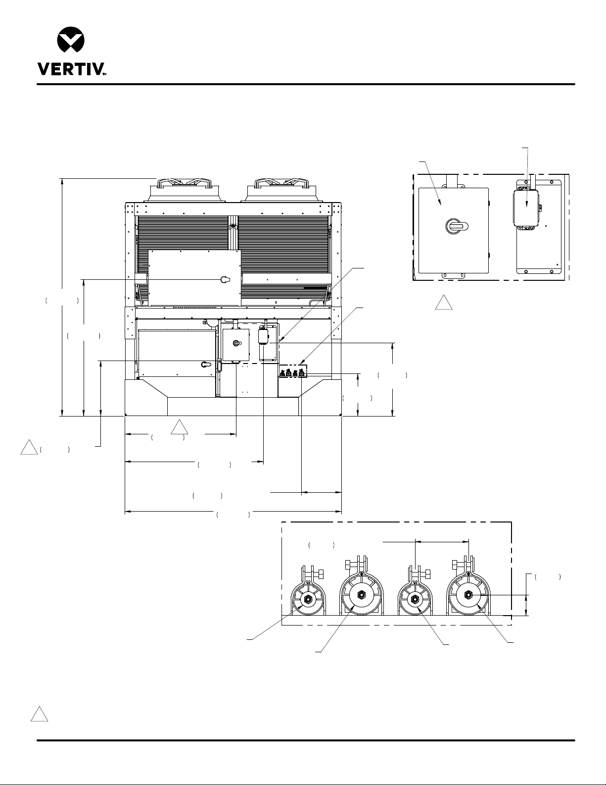
LIEBERT® HEAT REJECTION SKID
PRIMARY CONNECTION LOCATIONS
MCV330 + ECONOPHASE + BASE ASSY 380V & 415V
LOW VOLTAGE CUSTOMER
CIRCUIT 1
CIRCUIT 2
HIGH VOLTAGE CUSTOMER
CONNECTION
B
CONNECTION
111"
2819mm
25 13/16"
2
655mm
BOTTOM OF BOX
63 11/16"
1617mm
2
52"
1320mm
CENTER OF BOX
Front View
64 11/16"
1644mm
CENTER OF BOX
18 5/8"
473mm
u 1/2" (13mm)
101 1/4"
2572mm
3"
76mm
TYP.
A
19 11/16"
501mm
u 1/2" (13mm)
34"
864mm
BOTTOM OF BOX
DETAIL B
(Field Electrical Connections)
2
1 3/16"
29mm
7/8" LIQUID LINE
CIRCUIT 1
Notes:
1. Field to provide hole for conduit for high voltage disconnect box and low voltage distribution panel.
2. High Voltage Customer Connection for:
Voltage Codes: 2=(380V/3 Phase/60Hz); G=(415V/3 Phase/50Hz)
DPN004954
Page :1 /1
Form No.: DPN001040_REV4
1 3/8" HOT GAS
CIRCUIT 1
DETAIL A
(PIPING CONNECTIONS)
7/8" LIQUID LINE
CIRCUIT 2
1 3/8" HOT GAS
CIRCUIT 2
REV : 1
REV DATE : 2/20
Page 91
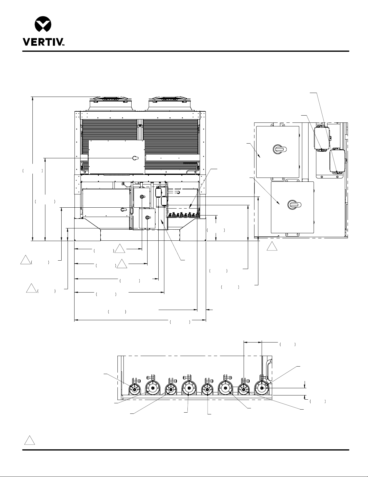
LIEBERT® HEAT REJECTION SKID
PRIMARY CONNECTION LOCATIONS
MCV330 (2) + ECONOPHASE (2) + BASE ASSY 380V & 415V
111"
2819mm
63 11/16"
1617mm
25 13/16"
2
655mm
BOTTOM OF BOX
TYP.
9 13/16"
2
249mm
BOTTOM OF BOX
SYSTEM 1
CIRCUIT 1
52"
1320mm
CENTER OF BOX
56 3/16"
1427mm
CENTER OF BOX
69 3/16"
1758mm
CENTER OF BOX
2
CENTER OF BOX
6 5/8"
168mm
2
64 11/16"
1644mm
u (1/2" 12.7mm)
SYSTEM 1
CIRCUIT 2
101 1/4"
2572mm
B
ALL CONNECTIONS MADE FROM SYSTEM 1 END (SHOWN)
LOW VOLTAGE CUSTOMER CONNECTION
SYSTEM 2
LOW VOLTAGE CUSTOMER CONNECTION
SYSTEM 1
HIGH VOLTAGE
CUSTOMER
CONNECTION
SYSTEM 1
A
HIGH VOLTAGE
CUSTOMER
CONNECTION
SYSTEM 2
19 5/8"
498mm
2
DETAIL B
(FIELD ELECTRICAL CONNECTIONS)
27 1/2"
699mm
BOTTOM OF BOX
34"
864mm
BOTTOM OF BOX
Form No.: DPN001040_REV4
DETAIL A
(PIPING CONNECTIONS)
7/8" LIQUID LINE
SYSTEM 1 CIRCUIT 1
1 3/8" HOT GAS
SYSTEM 1 CIRCUIT 1
7/8" LIQUID LINE
Notes:
1. Field to provide hole for conduit for high voltage disconnect box and low voltage distribution panel.
2. High Voltage Customer Connection for:
Voltage Codes: 2=(380V/3 Phase/60Hz); G=(415V/3 Phase/50Hz)
SYSTEM 1 CIRCUIT 2
DPN004953
Page :1 /1
1 3/8" HOT GAS
SYSTEM 1 CIRCUIT 2
7/8" LIQUID LINE
SYSTEM 2 CIRCUIT 1
3"
76mm
TYP.
1 3/8" HOT GAS
SYSTEM 2 CIRCUIT 1
u (1/2" / 13mm)
1 3/8" HOT GAS
SYSTEM 2 CIRCUIT 2
1 3/16"
TYP
29mm
7/8" LIQUID LINE
SYSTEM 2 CIRCUIT 2
REV : 1
REV DATE : 2/20
Page 92
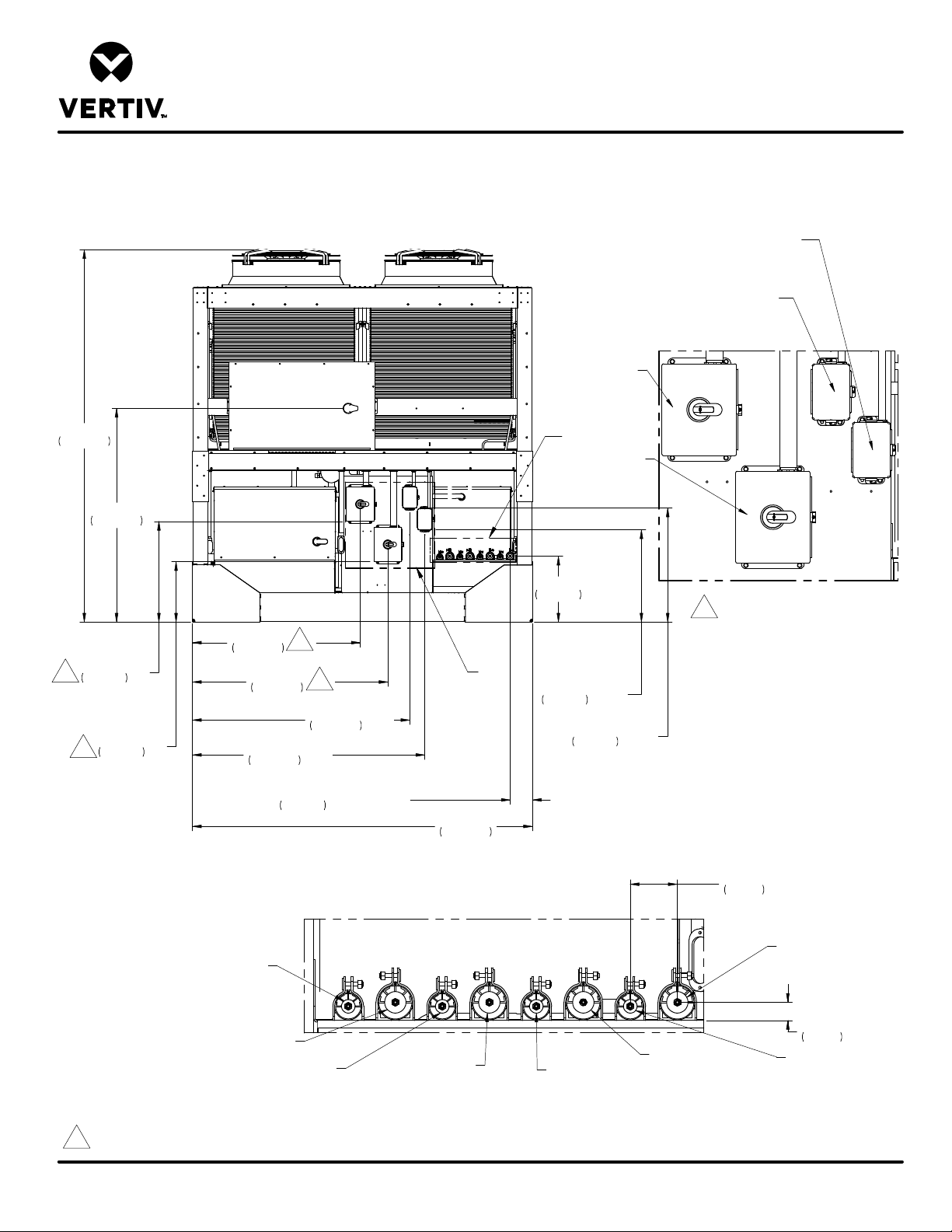
LIEBERT® HEAT REJECTION SKID
PRIMARY CONNECTION LOCATIONS
MCV330 (2) + ECONOPHASE (2) + BASE ASSY 460V & 575V
111"
2819mm
63 11/16"
1617mm
30"
2
762mm
BOTTOM OF BOX
TYP.
18"
2
457mm
BOTTOM OF BOX
SYSTEM 1
CIRCUIT 1
50"
1269mm
CENTER OF BOX
CENTER OF BOX
CENTER OF BOX
58 3/16"
1478mm
69 3/16"
1758mm
2
6 5/8"
168mm
2
64 11/16"
1644mm
CENTER OF BOX
u (1/2" 12.7mm)
SYSTEM 1
CIRCUIT 2
101 1/4"
2572mm
B
ALL CONNECTIONS MADE FROM SYSTEM 1 END (SHOWN)
LOW VOLTAGE CUSTOMER CONNECTION
SYSTEM 2
LOW VOLTAGE CUSTOMER CONNECTION
SYSTEM 1
HIGH VOLTAGE
CUSTOMER
CONNECTION
SYSTEM 1
A
HIGH VOLTAGE
CUSTOMER
CONNECTION
SYSTEM 2
19 5/8"
498mm
2
DETAIL B
(FIELD ELECTRICAL CONNECTIONS)
27 1/2"
699mm
BOTTOM OF BOX
34"
864mm
BOTTOM OF BOX
Form No.: DPN001040_REV4
DETAIL A
(PIPING CONNECTIONS)
7/8" LIQUID LINE
SYSTEM 1 CIRCUIT 1
1 3/8" HOT GAS
SYSTEM 1 CIRCUIT 1
7/8" LIQUID LINE
Notes:
1. Field to provide hole for conduit for high voltage disconnect box and low voltage distribution panel.
2. High Voltage Customer Connection for:
Voltage Codes: A=(460V/3 Phase/60Hz); B=(575V/3 Phase/60Hz)
SYSTEM 1 CIRCUIT 2
DPN003878
Page :1 /1
1 3/8" HOT GAS
SYSTEM 1 CIRCUIT 2
7/8" LIQUID LINE
SYSTEM 2 CIRCUIT 1
3"
76mm
TYP.
1 3/8" HOT GAS
SYSTEM 2 CIRCUIT 1
u (1/2" / 13mm)
1 3/8" HOT GAS
SYSTEM 2 CIRCUIT 2
1 3/16"
TYP
29mm
7/8" LIQUID LINE
SYSTEM 2 CIRCUIT 2
REV : 5
REV DATE : 2/20
Page 93
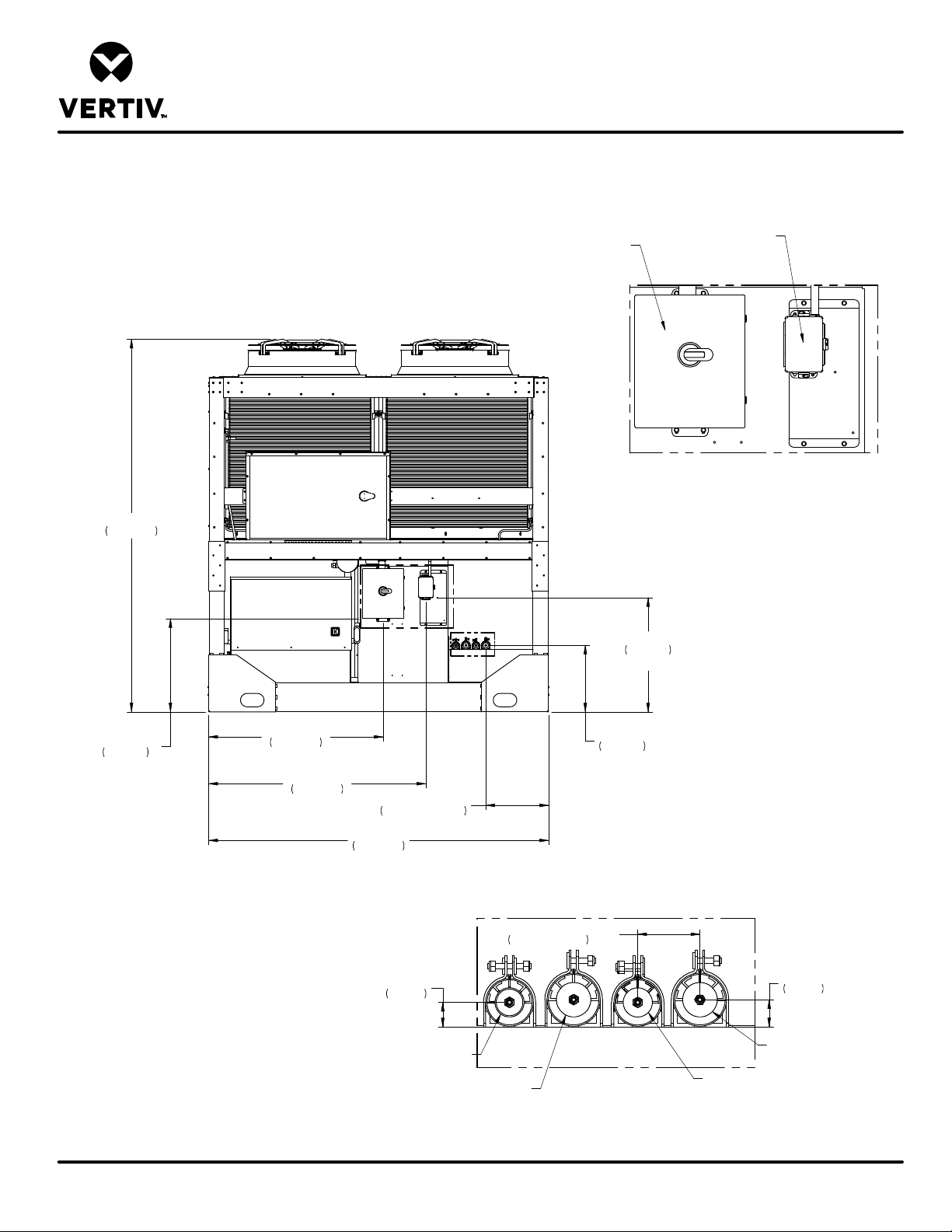
LIEBERT® HEAT REJECTION SKID
PRIMARY CONNECTION LOCATIONS
MCV440 + ECONOPHASE + BASE ASSEMBLY
111"
2819mm
Circuit 1 Circuit 2
B
High Voltage Customer
Connection
A
Low Voltage Customer
Connection
DETAIL B
(Field Electrical Connections)
34"
864mm
Bottom of Box
27 13/16"
706mm
Bottom of Box
Notes:
1. Field to provide hole for conduit for high voltage disconnect box
and low voltage distribution panel.
DPN004257
Page :1 /1
Form No.: DPN001040_REV4
52"
1320mm
Center of Box
64 11/16"
1644mm
Center of Box
18 11/16" ±1/2"
475mm ±13mm
101 1/4"
2572mm
Front
1 3/16"
29mm
Typ.
1-3/8" Liquid Line
Circuit 1
1-5/8" Hot Gas Line
Circuit 1
19 13/16"
504mm
DETAIL A
(Piping Connections)
3" ±1/2"
76mm ±13mm
Typ.
1-5/8" Hot Gas Line
Circuit 2
1-3/8" Liquid Line
Circuit 2
1 5/16"
33mm
Typ.
REV : 2
REV DATE : 2/20
Page 94
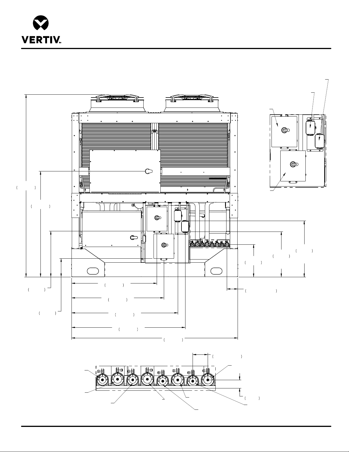
111"
2819mm
64 1/4"
1632mm
LIEBERT® HEAT REJECTION SKID
PRIMARY CONNECTION LOCATIONS
MCV440 (2) + ECONOPHASE (2) + BASE ASSEMBLY
SYSTEM 1
CIRCUIT 1
SYSTEM 1
CIRCUIT 2
LOW VOLTAGE CUSTOMER CONNECTION
SYSTEM 2
LOW VOLTAGE CUSTOMER CONNECTION
SYSTEM 1
HIGH VOLTAGE
CUSTOMER
CONNECTION
SYSTEM 1
HIGH VOLTAGE
CUSTOMER
CONNECTION
SYSTEM 2
(Field Electrical Connections)
DETAIL B
B
52"
27 13/16"
706mm
BOTTOM
OF BOX
BOTTOM
11 3/16"
284mm
OF BOX
1320mm
CENTER OF BOX
56 3/16"
1427mm
CENTER OF BOX
64 11/16"
1644mm
CENTER OF BOX
69 3/16"
1758mm
CENTER OF BOX
101 1/4"
2572mm
ALL CONNECTIONS MADE FROM SYSTEM 1 END OF UNIT (SHOWN)
DETAIL A
(PIPING CONNECTIONS)
1-3/8" LIQUID LINE
SYSTEM 1, CIRCUIT 1
1-5/8" HOT GAS
SYSTEM 1, CIRCUIT 1
1-3/8" LIQUID LINE
SYSTEM 1, CIRCUIT 2
Notes:
1. Field to provide hole for conduit for high voltage disconnect box and low voltage distribution panel.
1-5/8" HOT GAS
SYSTEM 1, CIRCUIT 2
A
3" ±1/2"
76mm ±13mm
TYP.
1-5/8" HOT GAS
SYSTEM 2, CIRCUIT 1
1-3/8" LIQUID LINE
SYSTEM 2, CIRCUIT 1
19 11/16"
501mm
6 5/8" ±1/2"
168mm ±13mm
1-5/8" HOT GAS
SYSTEM 2, CIRCUIT 2
1 11/16"
TYP.
42mm
1-3/8" LIQUID LINE
SYSTEM 2, CIRCUIT 2
27 1/2"
699mm
BOTTOM
OF BOX
34"
864mm
BOTTOM
OF BOX
Form No.: DPN001040_REV4
DPN004262
Page :1 /1
REV : 2
REV DATE : 2/20
Page 95
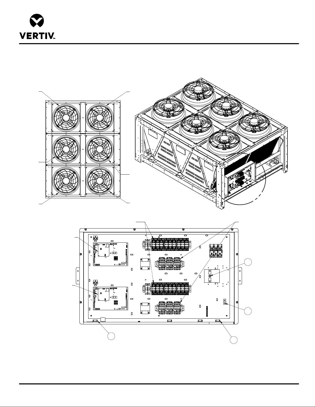
LIEBERT MCV
ELECTRICAL PANEL LAYOUT
MCV330
CIRCUIT 1
FAN 3
CIRCUIT 1
FAN 2
CIRCUIT 1
FAN 1
CONTROL
BOARD
CIRCUIT 1
FUSES
CIRCUIT 2
FAN 3
CIRCUIT 2
FAN 2
CIRCUIT 2
FAN 1
A
FAN CONTACTORS
Form No.: DPN001040_REV4
DPN003879
Page :1 /1
CONTROL
BOARD
CIRCUIT 2
4
KEY ELECTRICAL DETAILS:
1) Three phase electrical service – Terminals are on bottom of disconnect switch. Three phase service not by Liebert.
2) Earth ground – Field lug terminal for earth ground connection.
3) High voltage entrance located at the bottom of the enclosure.
4) Low voltage entrance located at the bottom of the enclosure.
Detail A
1
2
3
REV : 2
REV DATE : 8/17
Page 96
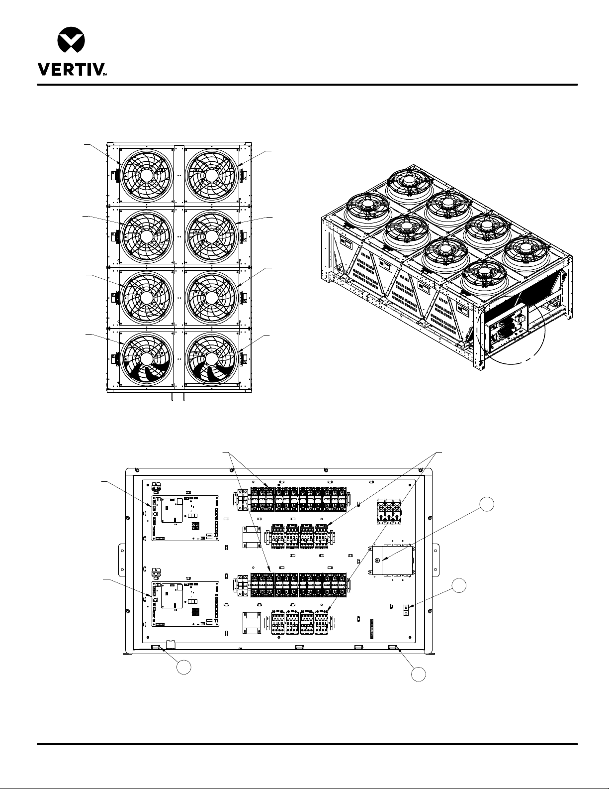
LIEBERT MCV
ELECTRICAL PANEL LAYOUT
MCV440
Circuit 1
Fan 4
Circuit 1
Fan 3
Circuit 1
Fan 2
Circuit 1
Fan 1
Circuit 2
Fan 4
Circuit 2
Fan 3
Circuit 2
Fan 2
Circuit 2
Fan 1
A
CONTROL BOARD
CIRCUIT 1
CONTROL BOARD
CIRCUIT 2
FUSES
4
KEY ELECTRICAL DETAILS:
1) Three phase electrical service – Terminals are on bottom of disconnect switch. Three phase service not by Liebert.
2) Earth ground – Field lug terminal for earth ground connection.
3) High voltage entrance located at the bottom of the enclosure.
4) Low voltage entrance located at the bottom of the enclosure.
Detail A
3
FAN CONTACTORS
1
2
Form No.: DPN001040_REV4
DPN004212
Page :1 /1
REV : 2
REV DATE : 10/17
Page 97
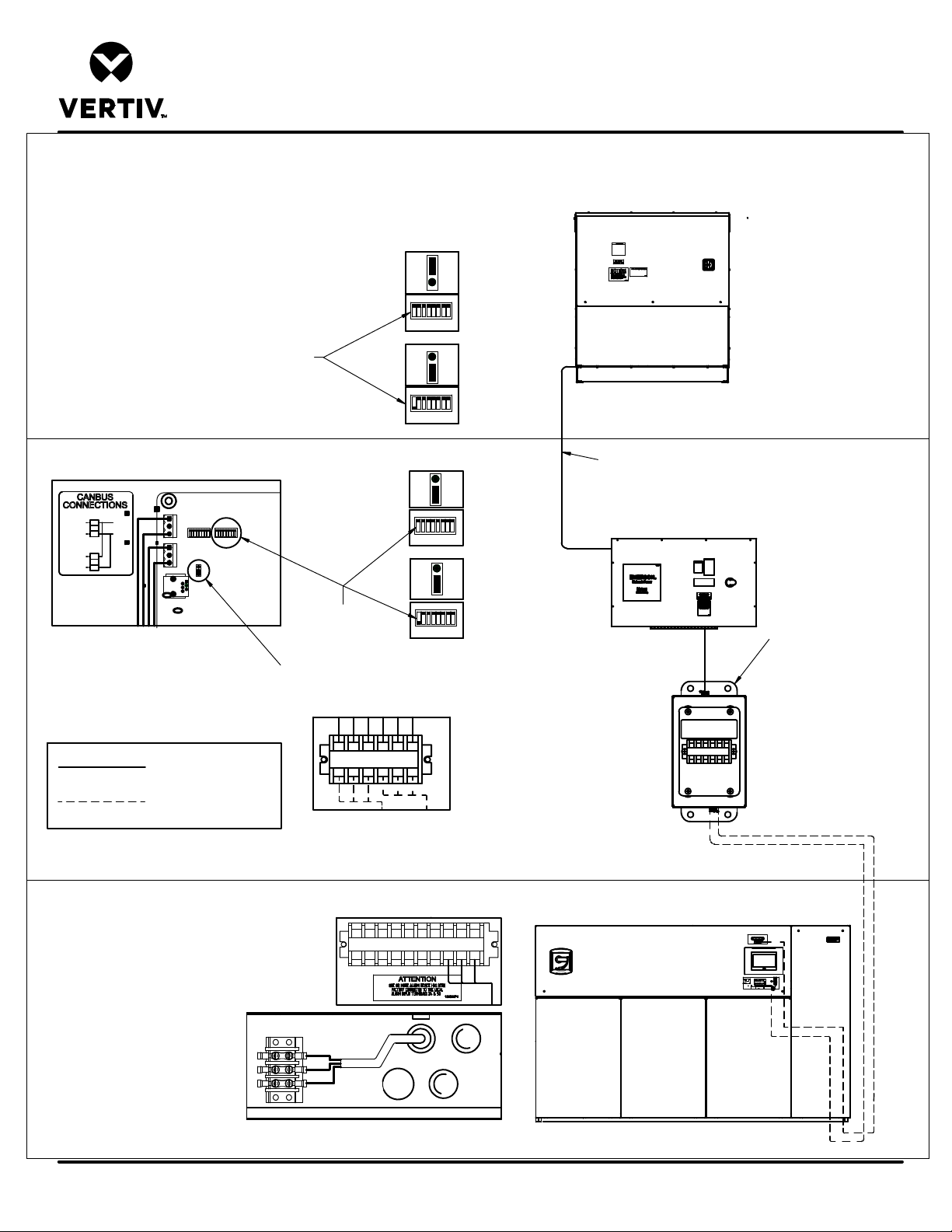
Liebert® MCV + Liebert® ECONOPHASE + BASE ASSY
Liebert
MCV
CONDENSER
Liebert
EconoPhase
Liebert
DSE
TB50
1
CAN H
2
OUTPUT
3
CAN L
TB49
1
2
INPUT
3
JUMPER AND DIPSWTICH
HL
TB50
HL
TB49
DETAIL 3
LOCATION
LIEBERT® HEAT REJECTION SKID
CANbus & INTERLOCK CONNECTIONS
ECONOPHASE CONTROL
BOARDS (FACTORY SET)
CIRCUIT 1
J6
31
ON
SW6
CAN
CANBUS
ADDRESSING
DIPSWITCH
ON
SW6
CAN
J6
31
CANBUS
ADDRESSING
DIPSWITCH
CIRCUIT 2
J6
31
ON
SW6
CAN
CONDENSER CONTROL
BOARDS (FACTORY SET)
CIRCUIT 1
1 3
J6
ON
SW6
CAN
CIRCUIT 2
1 3
J6
ON
SW6
CAN
CANBUS
TERMINATION
JUMPER
NOTE:
ONE Liebert DSE system
shown for simplicity.
3
®
CANBUS COMMUNICATION CABLE
®
3
LOW VOLTAGE
JUNCTION BOX
Form No.: DPN001040_REV4
FACTORY WIRED
FIELD INSTALLED
SEE SHEET 2 FOR
COMPONENT
NOTES, CABLE NOTES, &
WIRE NOTES
DPN003886
Page :1 /2
71
70
SH
49-1
49-3
230
A
B
70
71
230
DETAIL 4 LOW VOLTAGE JUNCTION BOX
DETAIL 2
HEAT REJECTION INTERLOCK (B)
23071
70
B
SH
A
49-1
49-3
DETAIL 1 CANBUS CABLE CONNECTION (A)
SH
49-1
49-3
4
A
B
2
1
®
REV : 4
REV DATE : 2/20
Page 98

LIEBERT® HEAT REJECTION SKID
CANbus & INTERLOCK CONNECTIONS
Liebert® MCV + Liebert® ECONOPHASE + BASE ASSY
COMPONENT NOTES:
1. COMPONENT APPEARANCE, ORIENTATION, AND POSITION MAY VARY BETWEEN PRODUCT LINES. TERMINAL NAMES REMAIN CONSTANT.
2. ALL CIRCUITS TO THESE CONNECTION POINTS REMAIN CONSTANT.
CAN & CABLE NOTES (A):
1. CABLE MUST HAVE THE FOLLOWING SPECIFICATIONS:
- BRAIDED SHIELD OR FOIL SHIELD WITH DRAIN WIRE
- SHIELD MUST BE WIRED TO GROUND AT INDOOR UNIT
- 22-18AWG STRANDED TINNED COPPER
- TWISTED PAIR (MINIMUM 4 TWISTS PER FOOT)
- LOW CAPACITANCE (15pF/FT OR LESS)
- MUST BE RATED TO MEET LOCAL CODES AND CONDITIONS.
- EXAMPLES BELDEN 89207 (PLENUM RATED), OR ALPHA WIRE 6454 CATEGORY 5, 5E, OR HIGHER.
2. DO NOT RUN IN SAME CONDUIT, RACEWAY, OR CHASE AS HIGH VOLTAGE WIRING.
3. FOR CANBUS NETWORK LENGTHS GREATER THAN 450FT(137M), CONTACT LIEBERT FACTORY.
INTERLOCK WIRE NOTES (B):
1. FIELD SUPPLIED WIRE
- 3 CONDUCTOR 18AWG OR GREATER
- RATED 600V
2. RUN FIELD SUPPLIED WIRES BETWEEN THE INDOOR UNIT AND THE LOW VOLTAGE JUNCTION BOX.
Form No.: DPN001040_REV4
DPN003886
Page :2 /2
REV : 4
REV DATE : 2/20
Page 99

Vertiv | Lieb ert® MCV Installer/User Guide
Page 100

Vertiv.com | Vertiv Headquarters, 1050 Dearborn Drive, Columbus, OH, 43085, USA
© 2020 Vertiv Group Corp. All rights reserved. Vertiv and the Vertiv logo are trademarks or registeredtrademarks of Vertiv GroupCorp. All other names and logos referred to are trade
names, trademarks or registered trademarks of their respective owners. While every precaution has been taken to ensure accuracy and completeness herein, Vertiv Group Corp.
assumes no responsibility, and disclaims all liability, for damages resulting from use of this information or for any errors or omissions. Specifications are subject to change without
notice.
SL-19539_REV-6_06-20
 Loading...