

Vertiv LIEBERT PSI5 MINI-TOWER Series, LIEBERT PSI5 MINI-TOWER PSI5-1500MT120, LIEBERT PSI5 MINI-TOWER PSI5-750/1100MT120 Quick Installation User's Manual
LIEBERT PSI5™ UPS
MINI-TOWER (MT) SERIES
Quick Installation User Guide
I M P O RTA N T: Before installing,
connecting to supply or operating
your Liebert PSI5
review the Safety and Regulatory
Statements sheet. For detailed
installation, operating, maintenance
and troubleshooting information
refer to the PSI5TM User Guide
available at www.VertivCo.com.
TM
UPS, please
INS TALLATION
Inspect the UPS for any signs of
obvious damage. If damage is
visible, do not proceed and call our
warranty support line for
assistance at 1-800-222-5877
menu option 3, or email at
microups.warranty@vertivco.com.
Install the PSI5TM UPS in a
temperature-controlled
environment that is free of
corrosive and conductive
contaminants. Avoid locations near
heat or water sources and exposed
to direct sunlight. For proper
ventilation, leave four inches
clearance on all sides of the UPS.
The input outlet should be nearby
and easily accessible.
NOTE : This UPS is not for use in a
computer room as defined in the
standard for the protection of
electronic computer/data processing
equipment of ANSI/NFPA 75.
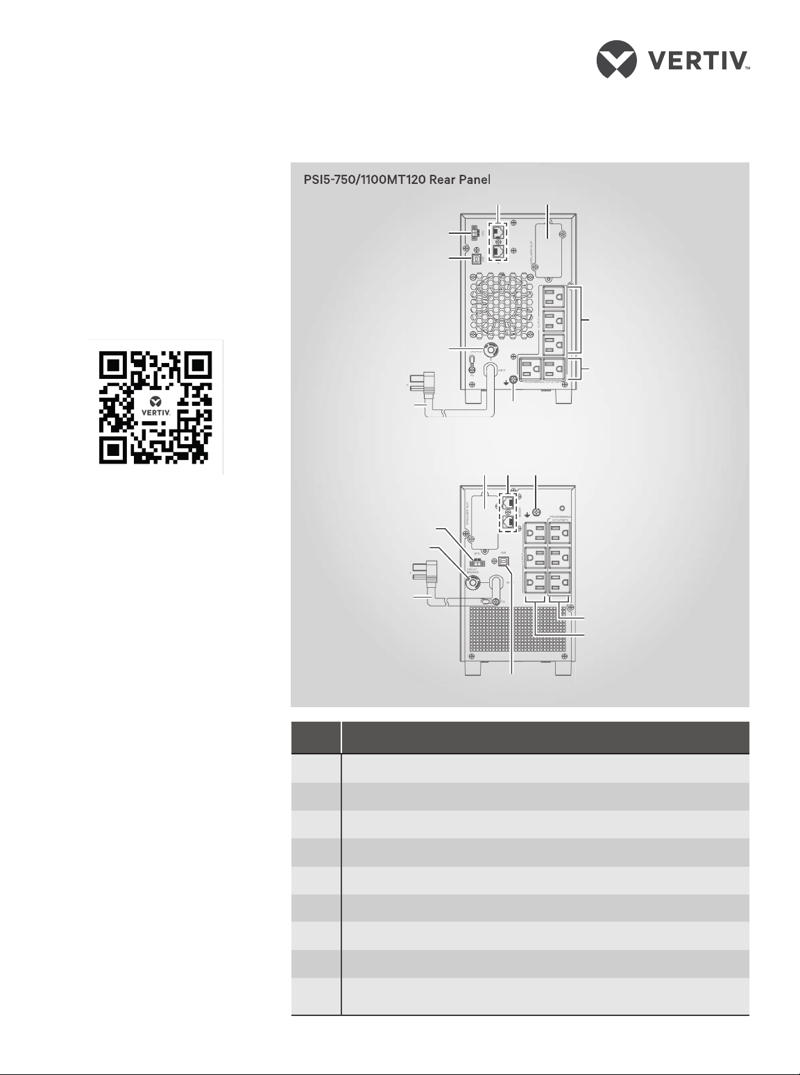
PSI5-750/1100MT120 Rear Panel
2
6
7
3
8
9
PSI5-1500MT120 Rear Panel
1
26 1
7
8
9
3
# Description
1 Ground screw
2 Network/Phone/DSL surge protection
3 USB port
4 Programmable receptacles
5 Non-programmable receptacles
6 SNMP IntelliSlot port
7 Emergency Power O (EPO) connector
5
4
4
5
8 Input circuit breaker
9 AC input
590-1992-665A 1
LIEBERT PSI5™ UPS MINI-TOWER (MT) SERIES
Quick Installation User Guide
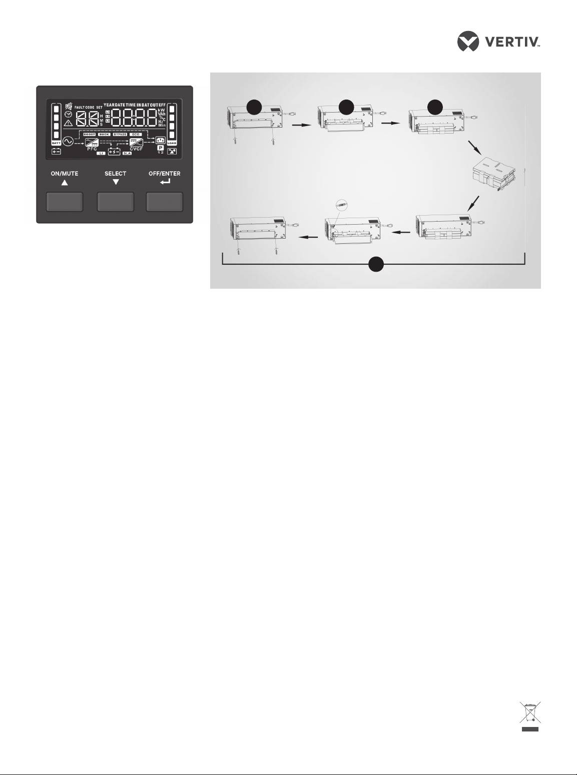
PSI5TM MT Display
OPERATION
1. Starting up the UPS
Plug the UPS input plug into a
stable 120VAC source. The LCD
display briefly turns on and the
batteries begin charging. Press
and hold the ON/MUTE button
for two seconds until the display
flashes On. The UPS is in
Battery Self Test mode for 10
seconds. After a successful
battery self-test, the UPS is in
On Mode.
2. Shutting down the UPS
Press and hold the OFF/ENTER
button for two seconds, turning
the battery-backed-up outlets
o . Disconnect the input power.
3. Fully shutting down
the UPS
Perform the normal shutdown
sequence. Remove internal
batteries as shown in the
Battery Replacement
instructions. The unit is now
fully shut down.
BATTERY REPLACEMENT
Before you proceed, please review
the battery safety precautions
available at https://www.vertivco.
com/ComplianceRegulatoryInfo.
You may safely replace the internal
battery pack. See the Specifications
in the User Guide online at www.
VertivCo.com for the part number
of the replacement battery for your
PSI5TM MT Battery Replacement
1
UPS model number.
NOTE : Replace the battery with
the same type and number
asoriginally installed.
2
1. Removing the battery
cover screws
Place the unit on its left side
and remove the six screws
holding the metal battery cover
plate in place.
2. Removing the battery
cover
Remove the metal battery
cover from the unit.
3. Removing the battery box
Slide out the existing battery
box and disconnect the two
halves of the battery connector.
4. Installing the new battery
Orient the new battery in the
same way as the original
battery, connect the two halves
of the battery connector, then
slide them into the UPS.
Replace the metal plate and
secure with the six screws.
5. Testing the new battery
Press and hold the power
button for three seconds to
initiate the Battery-Self Check
3
4
mode to clear any previous
battery fault warning.
6. Disposing of
the old battery
Properly dispose of old
batteries at an appropriate
recycling center or return them
to Vertiv in the packing material
for the replacement batteries.
To contact Vertiv Technical Support: visit www.VertivCo.com
© 2019 Verti v Co. All rights res erved. Vertiv an d the Vertiv logo are tra demarks or regis tered trademar ks of Vertiv Co. All othe r names and logo s referred to are trad e names,
tradema rks or registere d trademarks of the ir respective own ers. While ever y precaution ha s been taken to ensu re accuracy and co mpleteness h erein, Vertiv Co. a ssumes no
respon sibility, and disc laims all liabili ty, for damages res ulting from use of th is information or fo r any errors or omis sions. Speci fications are s ubject to change w ithout notice.
2 590-1992-665A

SERIE MINITORRE (MT)
PSI5-750/1100MT120
UPS LIEBERT PSI5™
Guía de uso e instalación
IMPORTANTE: antes de instalar,
conectar la alimentación u operar el
UPS Liebert PSI5
de declaraciones regulatorias y de
seguridad. Para obtener información
detallada sobre instalación,
funcionamiento, mantenimiento y
solución de problemas, consulte la
Guía de uso del PSI5TM, disponible
en www.VertivCo.com.
TM
, consulte la hoja
INSTALACIÓN
Inspeccione el UPS para detectar
signos de daños evidentes. Si hay
daños visibles, no continúe y llame a
nuestra línea de soporte de garantía
al 1-800-222-5877, opción de menú
3 o envíe un correo electrónico a
microups.warranty@vertivco.com.
Instale el UPS PSI5TM en un entorno
de temperatura controlada que no
contenga contaminantes
corrosivos ni conductivos. Evite los
lugares cercanos a fuentes de calor
o agua y la exposición a la luz solar
directa. Para una ventilación
adecuada, deje un espacio libre de
aproximadamente diez centímetros
a cada lado del UPS.
La toma de entrada debe estar en
un lugar cercano y de fácil acceso.
NOTA: este UPS no está pensado
para utilizarse en una sala de
computadoras, según la definición
de la norma para la protección de
computadoras electrónicas/equipos
de procesamiento de datos de ANSI/
NFPA 75.
Panel posterior PSI5-750/1100MT120
2
6
7
3
5
8
4
9
Panel posterior PSI5-1500MT120
1
26 1
7
8
9
4
5
3
# Descripción
1 Tornillo de puesta a tierra
2 Protección contra sobretensión para red/teléfono/DSL
3 Puerto USB
4 Receptáculos programables
5 Receptáculos no programables
6 Puerto SNMP IntelliSlot
7 Conector EPO (Apagado de emergencia)
8 Disyuntor de entrada
9 Entrada de CA
590-1992-665A 3
 Loading...