

Page 1

Liebert®
PFD™ Prop Fan Digital Condensing Unit
ThermalManagementSystems
Installer/User Guide
Page 2

The information contained in this document is subject to change
without notice and may not be suitable for all applications. While
every precaution has been taken to ensure the accuracy and
completeness of this document, Vertiv assumes no responsibility
and disclaims all liability for damages resulting from use of this
information or for any errors or omissions. Refer to other local
practices or building codes as applicable for the correct methods,
tools, and materials to be used in performing procedures not
specifically described in this document.
The products covered by this instruction manual are manufactured
and/or sold by Vertiv This document is the property of Vertiv and
contains confidential and proprietary information owned by Vertiv.
Any copying, use or disclosure of it without the written permission
of Vertiv is strictly prohibited.
Names of companies and products are trademarks or registered
trademarks of the respective companies. Any questions regarding
usage of trademark names should be directed to the original
manufacturer.
Technical Support Site
If you encounter any installation or operational issues with your product, check the pertinent
section of this manual to see if the issue can be resolved by following outlined procedures.
Visit https://www.VertivCo.com/en-us/support/ for additional assistance.
Vertiv | Liebert® PFD™ Installer/User G uide
Page 3
TABLE OF CONTENTS
1 Important Safety Instructions 5
1.1 Agency Listed 6
2 Nomenclature and Components 7
2.1 PFD Model Number Nomenclature 7
2.2 Component Location 8
3 Pre-installation PreparationandGuidelines 9
3.1 Planning Dimensions 9
3.1.1 Location Considerations for Outdoor Condensing Unit 9
3.2 Connections and System Setup 10
3.3 PFD Unit Weights 10
3.4 Equipment Inspection and Handling 10
4 Piping and Refrigerant Requirements 11
4.1 Refrigerant Piping 11
4.1.1 Refrigerant Piping Guidelines forAir-cooledSystems 12
4.1.2 Piping when Condensing Unit is Above or Below Evaporator 13
4.2 Refrigerant-line Sizes and Equivalent Lengths 14
4.2.1 Refrigerant Charge Requirements 14
4.2.2 Additional Oil Requirements for Digital-scroll Compressors 19
5 Electrical Connection Requirements 21
5.1 Low-voltage, Control Connections 22
6 Checklist for Completed Installation 23
7 Initial Start-up Checks andCommissioning ProcedureforWarrantyInspection 25
8 Maintenance 27
8.1 General Maintenance 28
8.2 Compressor Maintenance 28
8.2.1 Compressor Oil 28
8.2.2 Replacement Compressors 28
8.2.3 Compressor Motor Burnout 29
8.2.4 Unloading Solenoid(s) on a Digital-scroll Compressor 29
8.2.5 Replacing the Compressor 29
8.3 Condensing Unit Maintenance 30
9 Troubleshooting 31
Appendices 33
Appendix A: Technical Support and Contacts 33
Appendix B: Submittal Drawings 35
Vertiv | Liebert® PFD™ Installer/User Guide | 3
Page 4

Vertiv | Liebert® PFD™ Installer/User Guide | 4
Page 5

1 IMPORTANT SAFETY INSTRUCTIONS
SAVE THESE INSTRUCTIONS
This manual contains important safety instructions that should be followed during the installation and
maintenance of the Liebert®PFD. Read this manual thoroughly before attempting to install or operate
this unit.
Only qualified personnel should move, install or service this equipment.
Adhere to all warnings, cautions, notices and installation, operating and safety instructions on the unit
and in this manual. Follow all installation, operation and maintenance instructions and all applicable
national and local building, electrical and plumbing codes.
WARNING! Arc flash and electric shock hazard. Open all local and remote electric power-supply
disconnect switches, verify with a voltmeter that power is Off and wear appropriate,
OSHA-approved personal protective equipment (PPE) per NFPA 70E before working within the
electric control enclosure. Failure to comply can cause serious injury or death. Customer must
provide earth ground to unit, per NEC, CEC and local codes, as applicable. Before proceeding
with installation, read all instructions, verify that all the parts are included and check the
nameplate to be sure the voltage matches available utility power. The Liebert® controller does
not isolate power from the unit, even in the “Unit Off” mode. Some internal components require
and receive power even during the “Unit Off” mode of the controller. The only way to ensure
that there is NO voltage inside the unit is to install and open a remote disconnect switch. Refer
to unit electrical schematic. Follow all local codes.
WARNING! Risk of over-pressurization of the refrigeration system. Can cause explosive
discharge of high-pressure refrigerant, loss of refrigerant, environmental pollution, equipment
damage, injury, or death. This unit contains fluids and gases under high pressure. Use extreme
caution when charging the refrigerant system. Do not pressurize the system higher than the
design pressure marked on the unit's nameplate. Relieve pressure before cutting into or
making connections/disconnections to the piping system.
Do not close off any field-installed, refrigerant-line isolation valves for repairs unless a
pressure-relief valve is field- installed in the line between the isolation valve and the check valve.
The pressure-relief valve must be rated 5% to 10% higher than the system-design pressure. An
increase in ambient temperature can cause the pressure of the isolated refrigerant to rise and
exceed the system-design pressure rating (marked on the unit nameplate).
WARNING! Risk of contact with high-speed, rotating fan impeller blades. Can cause injury or
death. Open all local and remote electric power-supply disconnect switches, verify with a
voltmeter that power is off, and verify that all fan impellers have stopped rotating before
working in the unit cabinet.
WARNING! Risk of electric shock. Can cause serious injury or death. The Liebert® iCOM
microprocessor does not isolate power from the unit, even in the "Unit Off" mode. Some internal
components require and receive power even during the "unit off" mode of the Liebert® iCOM
control. Open all local and remote electric power disconnect switches and verify with a
voltmeter that power is Off before working on any component of the system.
CAUTION: Risk of contact with sharp edges, splinters, and exposed fasteners. Can cause
injury. Only properly trained and qualified personnel wearing appropriate, OSHA-approved PPE
should attempt to move, lift, remove packaging from or prepare the unit for installation.
1 Important Safety Instructions 5
Page 6
NOTICE
NOTICE
CAUTION: Risk of contact with hot surfaces. Can cause injury. The compressor, refrigerant
discharge lines, fan motor, and some electrical components are extremely hot during unit
operation. Allow sufficient time for them to cool to a touch-safe temperature before working
within the unit cabinet. Use extreme caution and wear appropriate, OSHA-approved PPE when
working on or near hot components.
Risk of oil contamination with water. Can cause equipment damage.
Liebert®PFD systems require the use of POE (polyolester) oil. POE oil absorbs water at a much
faster rate when exposed to air than previously used oils. Because water is the enemy of a
reliable refrigeration system, extreme care must be used when opening systems during
installation or service. If water is absorbed into the POE oil, it will not be easily removed and will
not be removed through the normal evacuation process. If the oil is too wet, it may require an oil
change. POE oils also have a property that makes them act as a solvent in a refrigeration
system. Maintaining system cleanliness is extremely important because the oil will tend to
bring any foreign matter back to the compressor.
Risk of improper refrigerant charging. Can cause equipment damage.
Refrigerant charge must be weighed into air-cooled compressorized systems before they are
started. Starting digital scroll compressors without proper refrigerant charging can cause the
compressors to operate at less than 5°F (–15°C) evaporator temperature and at less than
55psig (379kPa). Operation for extended periods at less than 55psig (379kPa) can cause
premature compressor failure.
NOTICE
Risk of damage from forklift. Can cause unit damage. Keep tines of the forklift level and at a
height suitable to fit below the skid and/or unit to prevent exterior and/or underside damage.
NOTICE
Risk of improper storage. Can cause unit damage.
Keep the unit upright, indoors and protected from dampness, freezing temperatures and
contact damage.
1.1 Agency Listed
Standard 60-Hz units are CSA Certified to the harmonized U.S. and Canadian product safety standard
CSA C22.2 No 236/UL 1995 for “Heating and Cooling Equipment” and are marked with the CSA c-us logo.
6
Vertiv | Liebert® PFD™ Installer/User G uide
Page 7
2 NOMENCLATURE AND COMPONENTS
This section describes the model number for Liebert® PFD units and components.
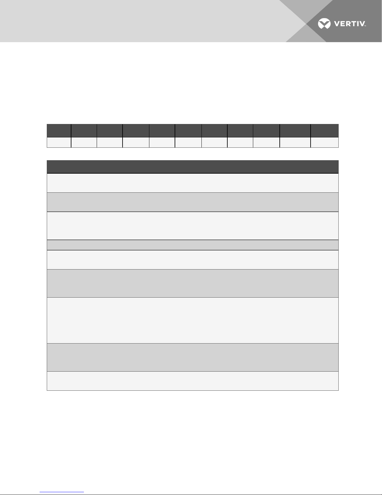
2.1 PFD Model Number Nomenclature
Table 2.2 below describes each digit of the model number.
Table 2.1 Prop-fan Condensing Unit Model-number Example
1 2 3 4 5 6 7 8 9 10 11
P F D 0 6 7 A — A L 1
Table 2.2 Model-number Digit Definitions for Outdoor, Prop-fan Condensing Units
Digit and Description
Digits 1, 2 = The base unit
PF = Prop-fan condensing unit
Digit 3 = Compressor type
D = Digital-scrollcompressor
Digit 4= Sound level
0 = Standard
Z = Quiet-Line (067 models only)
Digits 5 and 6 = Nominal Capacity, 1,000 BTU/hr
Digit 7= Unit type
A = Air-cooled
Digit 8 = Coil type
— = Standard coil
C = Coated coil
Digit 9= Supplypower
A = 460V / 3ph / 60Hz
B = 575V/ 3ph/ 60Hz(054 and067 models only)
P = 208-230 V / 1 ph / 60 Hz (037 model only)
Y = 208-230 V / 3ph/ 60Hz
Digit 10 = Head-pressure control
L = 95°F Ambient, Liebert® Lee-Temp™
H = 105°F Ambient, Liebert® Lee-Temp™ (not available on 048 model)
Digit 11= Refrigerant
1 = R-410A, field-supplied
2 Nomenclature and Components 7
Page 8
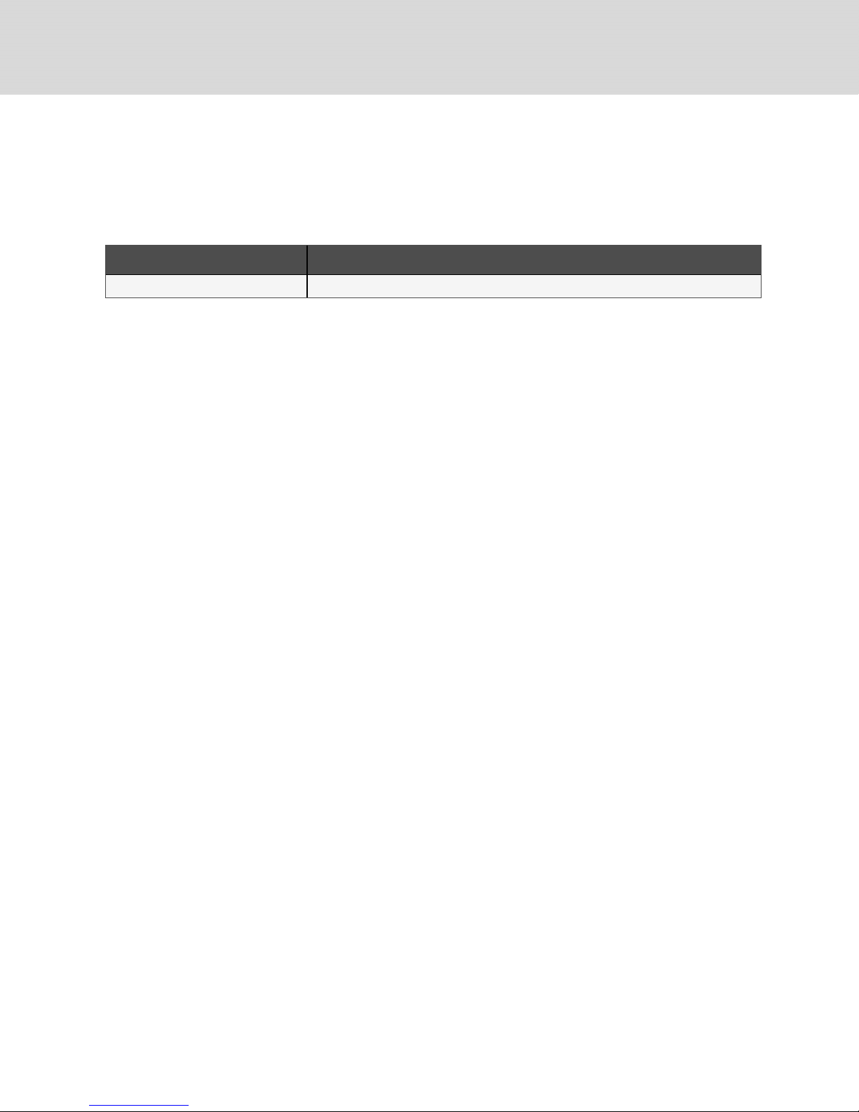
2.2 Component Location
The unit component locations are described in the submittal documents included in the Submittal
Drawings on page35.
The following tables list the relevant documents by number and title.
Table 2.3 Component-location Drawings
Document Number Title
DPN004180 PFDCondensing Unit, 3-, 4-, and 5-ton
8
Vertiv | Liebert® PFD™ Installer/User G uide
Page 9
3 PRE-INSTALLATION PREPARATIONANDGUIDELINES
NOTE: Before installing unit, determine whether any building alterations are required to run piping,
wiring and ductwork. Follow all unit dimensional drawings and refer to the submittal engineering
dimensional drawings of individual units for proper clearances.
Refer to PFD Model Number Nomenclature on page7, and submittal drawings to determine the type of
system being installed and anticipate building alterations, piping and ductwork needed.
The unit dimensions, pipe-connection locations, and piping schematics are described in the submittal
documents included in the Submittal Drawings on page35.
• Allow at least the minimum recommended clearances maintenance, and service. See the
appropriate submittal drawings for dimensions.
• Be mindful of the placement of the PFD in relation to the connected evaporator unit, other
outside units, barriers, and walls for air flow clearance, equivalent piping distances, and
differences in elevation between the PFD and connected evaporator unit.
• When applications do not meet or exceed any of these specifications, contact your Vertiv
representative.
3.1 Planning Dimensions
The unit dimensions described in the submittal documents included in the Submittal Drawings on
page35.
The following table lists the relevant documents by number and title.
Table 3.1 Dimension Planning Drawings
Document Number Title
Outdoor Condensing Unit
DPN004058 Cabinet dimensions, 5-ton, top discharge
DPN004063 Cabinet dimensions, 3-, 4-, and 5-ton, horizontaldischarge
DPN004066 Optional anchoring plan, 3-, 4-, and 5-ton, horizontaldischarge
3.1.1 Location Considerations for Outdoor Condensing Unit
Observe the following when planning the installation of the outdoor unit:
• To ensure a satisfactory air supply, locate air-cooled condensing units in an environment with
clear air, away from loose dirt and foreign matter that may clog the coil.
• Condensing units must not be located in the vicinity of steam, hot air or fume exhausts or
closer than 18 inches from a wall, obstruction or adjacent unit.
• For multiple-unit installations, space the units so that the hot, condensing-unit exhaust air is
not directed toward the air inlet of an adjacent unit.
• Avoid areas where heavy snow will accumulate at air inlet and discharge locations.
• The condensing unit should be located for maximum security and maintenance accessibility.
Avoid ground-level sites with public access. Install a solid base, capable of supporting the
weight of the condensing unit.
• The base should be at least 2in. (51mm) higher than the surrounding grade and 2 in. (51mm)
larger than the dimensions of the condensing-unit base. For snowy areas, a base of sufficient
height to clear snow accumulation must be installed.
Before beginning, refer to Piping and Refrigerant Requirements on page11 for unit placement, piping
guidelines, and refrigerant-charge requirements for your system.
The condensing unit must be located within the maximum distance from evaporator per the guidelines
listed in Pipe length and condenser elevation relative to evaporator.
3 Pre-installation PreparationandGuidelines 9
Page 10
3.2 Connections and System Setup
• Electrical service is required for all models. Electrical service must conform to national and local
electrical codes. See equipment nameplate for details.
• Plan the routing of wiring, piping and ductwork to the unit. Refer to the appropriate piping
connection location drawings, piping schematics, and electrical-connection drawings for your
system in .
3.3 PFD Unit Weights
Table 3.2 PFD Unit weights
Model # Weight, lb (kg)
PFD037A-L 244 (111)
PFD037A-H 351 (159)
PFD054A-L 351 (159)
PFD067A-L 351 (159)
PFD067A-H 488 (222)
PFDZ67A-L 488 (222)
3.4 Equipment Inspection and Handling
SAFETY INFORMATION
WARNING! Risk of improper moving, lifting, or handling of the unit. Can cause equipment
damage, injury or death. Read all of the following instructions and verify that all lifting and
moving equipment is rated for the weight of the unit before attempting to move, lift, remove
packaging from or prepare the unit for installation. Unit weights are specified in Table 3.2
above.
CAUTION: Risk of contact with sharp edges, splinters, and exposed fasteners. Can cause
injury. Only properly trained and qualified personnel wearing appropriate, OSHA-approved PPE
should attempt to move, lift, remove packaging from or prepare the unit for installation.
NOTICE
Risk of damage from forklift. Can cause unit damage. Keep tines of the forklift level and at a
height suitable to fit below the skid and/or unit to prevent exterior and/or underside damage.
When the unit arrives, inspect all items for any visible or concealed damage. Report any damage to the
carrier immediately and file a damage claim. Send a copy of the claim to your Vertiv representative.
If possible, maintain equipment and packaging until it is at the installation location.
10
Vertiv | Liebert® PFD™ Installer/User G uide
Page 11
4 PIPING AND REFRIGERANT REQUIREMENTS
All refrigeration connections to the unit are sweat copper. Factory-installed piping brackets must not be
removed. Field-installed piping must be installed in accordance with local codes and must be properly
assembled, supported, isolated and insulated. Avoid piping runs through noise-sensitive areas, such as
office walls and conference rooms.
Refer to specific text and detailed diagrams in this manual for other unit-specific piping requirements.
The pipe connection locations, piping general arrangement and schematics are described in the
submittal documents included in the Submittal Drawings on page35.
The following tables list the relevant documents by number and title.
Table 4.1 Piping General-arrangment Drawings
Document Number Title
DPN004060 Piping arrangement, 3-, 4- and 5-ton split-system
Table 4.2 Piping Connection Drawings
Document Number Title
DPN004059 Primary connection locations, top discharge
DPN004064 Primaryconnection locations, horizontaldischarge
4.1 Refrigerant Piping
WARNING! Risk of over-pressurization of the refrigeration system. Can cause explosive
discharge of high-pressure refrigerant, loss of refrigerant, environmental pollution, equipment
damage, injury, or death. This unit contains fluids and gases under high pressure. Use extreme
caution when charging the refrigerant system. Do not pressurize the system higher than the
design pressure marked on the unit's nameplate. Relieve pressure before cutting into or
making connections/disconnections to the piping system.
Do not close off any field-installed, refrigerant-line isolation valves for repairs unless a
pressure-relief valve is field- installed in the line between the isolation valve and the check valve.
The pressure-relief valve must be rated 5% to 10% higher than the system-design pressure. An
increase in ambient temperature can cause the pressure of the isolated refrigerant to rise and
exceed the system-design pressure rating (marked on the unit nameplate).
Consult local building and plumbing codes for installation requirements of additional pressure-relief
devices when isolation valves are field installed. Do not isolate any refrigerant circuits from overpressurization protection. The PFD condensing unit includes a factory-installed pressure-relief valve
mounted on top of the receiver. The valve is rated for a maximum working pressure of 675psig.
4 Piping and Refrigerant Requirements 11
Page 12

NOTICE
Risk of oil contamination with water. Can cause equipment damage.
Liebert®PFD systems require the use of POE (polyolester) oil. POE oil absorbs water at a much
faster rate when exposed to air than previously used oils. Because water is the enemy of a
reliable refrigeration system, extreme care must be used when opening systems during
installation or service. If water is absorbed into the POE oil, it will not be easily removed and will
not be removed through the normal evacuation process. If the oil is too wet, it may require an oil
change. POE oils also have a property that makes them act as a solvent in a refrigeration
system. Maintaining system cleanliness is extremely important because the oil will tend to
bring any foreign matter back to the compressor.
NOTICE
Risk of improper refrigerant charging. Can cause equipment damage.
Refrigerant charge must be weighed into air-cooled compressorized systems before they are
started. Starting digital scroll compressors without proper refrigerant charging can cause the
compressors to operate at less than 5°F (–15°C) evaporator temperature and at less than
55psig (379kPa). Operation for extended periods at less than 55psig (379kPa) can cause
premature compressor failure.
4.1.1 Refrigerant Piping Guidelines forAir-cooledSystems
• Evaporators and condensing units ship with an inert-gas holding charge. Do not vent the
evaporator and condensing unit until all refrigerant piping is in place, ready for connection to
the unit and condensing unit.
• Use copper piping with a brazing alloy with a minimum temperature of 1350°F (732°C), such as
Sil-Fos. Avoid soft solders, such as 50/50 or 95/5.
• Use a flow of dry nitrogen through the piping during brazing to prevent formation of copper
oxide scale inside the piping. When copper is heated in the presence of air, copper oxide forms.
POE oils will dissolve these oxides from inside the copper pipes and deposit them throughout
the system, clogging filter driers and affecting other system components.
• A pure dry nitrogen flow of 1-3 ft3/min (0.5-1.5 l/s) inside the pipe during brazing is sufficient to
displace the air. Control the flow using a suitable measuring device.
• Ensure that the tubing surfaces to be brazed are clean and that all burrs have been removed
from the ends of the tubes.
• Ensure that all loose material has been cleaned from inside the tubing before brazing.
• Protect all refrigerant line components within 18in. (460mm) of the brazing site by wrapping
them with a wet cloth or with a suitable heat-sink compound.
• Isolate piping from building using vibration-isolating supports.
• When sealing openings in walls and to reduce vibration transmission, use a soft, flexible
material to pack around the tubes to prevent tube damage.
• When installing remote condensing units above the evaporator, the suction gas lines should be
trapped at the evaporator. These traps will retain refrigerant oil in the off cycle. When the unit
starts, oil in the traps is carried up the vertical risers and returns to the compressors. For rises
over 25ft (7.6m), trap every 20ft (6m)or evenly-divided.
• Consult factory if piping run exceeds 150ft(46m) equivalent length.
• Keep piping clean and dry, especially on units with R-410A refrigerant.
• Avoid piping runs through noise-sensitive areas.
• Do not run piping directly in front of discharge air stream.
• Refrigerant oil – do not mix oil types.
Refer to ASHRAE Refrigeration Handbook for general, good-practice refrigeration piping.
12
Vertiv | Liebert® PFD™ Installer/User G uide
Page 13
NOTE: All indoor and outdoor suction-line piping must have 1/2 in. minimum of insulation. All outdoor
insulation must be UV and ozone resistant.
NOTE: Proper safety equipment and proper refrigeration tools are required when working with R-410A
refrigerant. Check unit serial tag for correct refrigerant type before topping-off or recharging a system.
NOTE: Refrigerant R-410A uses a POE (polyolester) lubricant. The refrigerant must be introduced and
charged from the cylinder only as a liquid.
NOTE: When installing field piping, you must take care to protect all refrigerant lines from the
atmosphere especially when using refrigerants with POE oils. Do not allow the piping to stand open to
air for more than 15minutes. Units designed for R-410A have a compressor that contains POEoil,
which quickly absorbs water from the air. The longer that the refrigerant piping is left open to air, the
harder it will be to fully evacuate the system. If left open too long, the POE oil may require replacement
to achieve the required vacuum level.
• Refer to Refrigerant-line Sizes and Equivalent Lengths on the next page,for recommended
refrigerant piping sizes based on equivalent pipe lengths.
• Refer to Refrigerant Charge Requirements on the next page, for the refrigerant-charge
requirements of the system.
4.1.2 Piping when Condensing Unit is Above or Below Evaporator
Refer to Table 4.3 below for the maximum vertical rise/fall between condensing unit and evaporator.
When installing remote condensing units above the evaporator, trap the suction gas line at the
evaporator as shown in Figure 4.1 on the next page. This trap will retain refrigerant oil during the "Off"
cycle. When the unit starts, oil in the trap is carried up the vertical riser and returns to the compressor.
When installing remote condensing units below the evaporator, trap the suction gas line with an inverted
trap the height of the evaporator as shown in the following figure. This prevents refrigerant migration to
the compressor during "Off" cycles.
Table 4.3 Pipe length and condensing unit elevation relative to
evaporator
Maximum Equivalent Pipe Length, ft (m)
150 (45) 50 (15) 15 (4.6)
Maximum
Condensing-unit Level
Above Evaporator, ft (m)
Maximum
Condensing-unit Level
BelowEvaporator, ft (m)
4 Piping and Refrigerant Requirements 13
Page 14
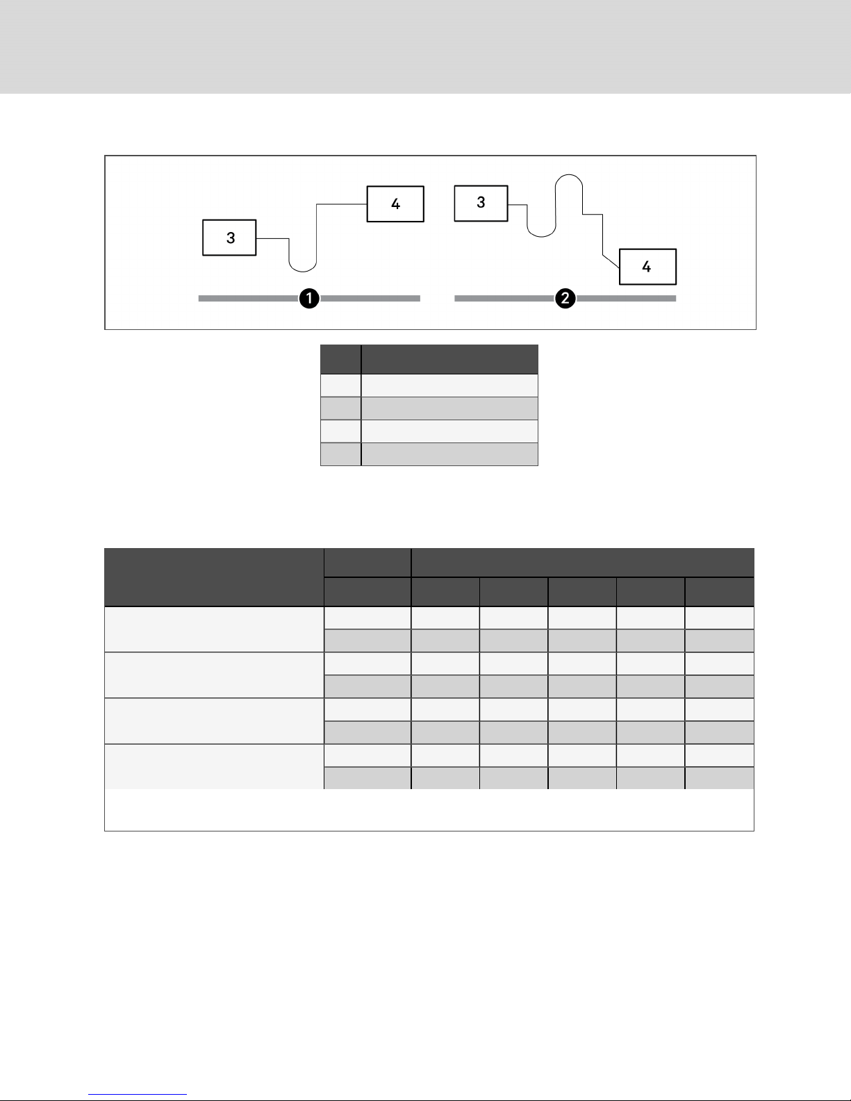
Figure 4.1 Refrigerant piping when condensing unit is above or below evaporator
Item Description
1 Condensing unit above evaporator
2 Condensing unit below evaporator
3 Evaporator
4 Condensing unit
4.2 Refrigerant-line Sizes and Equivalent Lengths
The following tables list the information required to field-install the refrigerant piping for the system.
Table 4.4 Recommended refrigerant line sizes, O.D.cubyequivalentlength
Equivalent Length, ft (m)
System Models
50 (15) 75 (23) 100 (30) 125 (38) 150 (45)
MT036E/PFD037A-*L or PFD037A-*H
MT048HE/PFD054A-*L
MT060HE/PFD067A-*L
MT060HE/PFDZ67A-*L or PFD067A-*H
Consult factory for proper line sizing for runs longer than maximum equivalent length shown.
1.Use one line size smaller on suction lines for vertical risers.
Suction line, in. 7/8 7/8 7/8 7/8 7/8
Liquid line, in. 1/2 1/2 1/2 1/2 1/2
Suction line, in. 7/8 1-1/8
Liquid line, in. 1/2 1/2 5/8 5/8 5/8
Suction line, in. 1-1/8 1-1/8 1-1/8 1-1/8 1-1/8
Liquid line, in. 1/2 5/8 5/8 5/8 5/8
Suction line, in. 1-1/8 1-1/8 1-1/8 1-1/8 1-1/8
Liquid line, in. 1/2 5/8 5/8 5/8 5/8
1
4.2.1 Refrigerant Charge Requirements
To calculate the charge requirements:
1. Determine the charge for your units by model number from the following tables.
2. Determine the charge for the piping by line size and length.
3. Add these all together to obtain the total refrigerant charge for your system.
1-1/8
1
1-1/8
1
1-1/8
1
14
Vertiv | Liebert® PFD™ Installer/User G uide
Page 15
Table 4.5 Indoor Evaporator Approximate R-410Arefrigerant charge
Model # Charge, lb (kg)
MT036HE 1 (0.45)
MT048HE 2.2 (1.0)
MT060HE 2.2 (1.0)
Table 4.6 Interconnecting piping refrigerant charge for R-410A, lbper 100ft (kgper30m)
Line Size,
O.D., in.
3/8 3.2 (1.4) —
1/2 5.9 (2.7) 0.2 (0.1)
5/8 9.6 (4.3) 0.4 (0.2)
3/4 14.3 (6.4) 0.6 (0.3)
7/8 19.8 (8.8) 0.8 (0.4)
1-1/8 33.8 (15.1) 1.4 (0.6)
1-3/8 51.5 (23.0) 2.1 (1.0)
Source:DPN003099 Rev. 1
Liquid Line,lb (kg) Suction Line, lb (kg)
Table 4.7 Liebert® PFD R-410A refrigerant charge
Model # Charge, lb (kg)
PFD037A-*L1 13.4 (6.1)
PFD037A-*H1 27 (12.2)
PFD054A-*L1 27 (12.2)
PFD067A-*L1 27 (12.2)
PFDZ67A-*L1 57 (25.8)
PFD067A-*H1 57 (25.8)
Evacuation and Leak-testing Air-cooled Systems
For proper leak-check and evacuation, you must open all system valves and account for all check valves,
see Figure 4.2 on the next page.
4 Piping and Refrigerant Requirements 15
Page 16

Figure 4.2 Valves and Connections
Item Description
1 Apply a manifold gauge hose on the suction-line Schraderport.
2 Apply a manifold gauge hose on the discharge-line Schrader port.
3 Remove the solenoid-valve holding coil then applysolenoid-valve service magnet to the valve.
4 External equalizer
5 Sensing bulb
6 Suction-pressure transducer
7 Suction line
8 Schrader port with valve core
9 Digital-scroll compressor
10 Discharge-temperature thermistor
11 High-pressure switch
12 Condenser coil
13 3-way head-pressure control valve
16
Vertiv | Liebert® PFD™ Installer/User G uide
Page 17

Item Description
14 Check valve
15 Pressure-balancing valve
16 Sight glass
17 Pressure-relief valve
18 Lee-Temp receiver
19 Receiver-heater pressure-limiting switch
Schrader port with valve core
NOTE: The system includes a factory-installed Schrader valve with core in the liquid line downstream of the
20
receiver. Proper evacuation of the condenser side of the system can be accomplished only using the downstream
Schrader valve. See the appropriate piping schematic for your system in Submittal Drawings on page35.
21 Liquid-line solenoid valve
22 Liquid line
23 Filter drier
24 Expansion valve
25 Evaporator coil
To evacuate and leak-test the system:
1. Open the liquid-line solenoid valve by removing the holding coil, and apply a solenoid-valve
service magnet to the valve.
2. Connect manifold-gauge hoses on the discharge- and suction-line Schrader ports, open the
service valves, and place a 150PSIG(1034kPa)charge of dry nitrogen with a tracer of
refrigerant, then check the system for leaks with a suitable leak detector.
3. After completion of leak testing, release the test pressure, (observe local code) and pull an
initial deep vacuum of 500microns on the system with a suitable pump.
4. After 4hours, check the pressure readings and, if they have not changed, break vacuum with
dry nitrogen. Pull a second and third vacuum to 500 microns or less. Re-check the pressure
after 2hours.
When the 3 checks are complete, proceed to Charging Air-cooled Systems below.
Charging Air-cooled Systems
NOTICE
Risk of improper refrigerant charging. Can cause equipment damage.
R-410A is a blended refrigerant and must be introduced and charged from the cylinder only as
a liquid.
When adding liquid refrigerant to an operating system, it may be necessary to add the
refrigerant through the valve in the compressor suction line. Care must be exercised to avoid
damage to the compressor. We recommend connecting a sight glass between the charging
hose and the compressor suction service valve. This will permit adjustment of the cylinder
hand valve so that liquid can leave the cylinder while allowing vapor to enter the compressor.
NOTICE
Risk of improper component re-installation. Can cause equipment damage.
Identify and mark location of the discharge pressure switch. It must be reinstalled in its original
location.
Initially charging the system:
1. Check the nameplate on the indoor unit for refrigerant type to use.
4 Piping and Refrigerant Requirements 17
Page 18

2. Refer to Refrigerant Charge Requirements on page14, and calculate the amount of charge for
the system including the evaporator, condensing unit, and interconnecting piping.
3. Accurately weigh-in as much of the system charge as possible before re-installing the coil on
the liquid-line solenoid valve and starting the unit.
Field Charge Verification
The unit receiver includes an integral sight glass to assist with charge verification in the field.
To verify the refrigerant charge:
1. To keep the unit operating, use the Service menu at the iCOMtouchscreen control:
• Touch the Service icon to display the service menu, then touch Diagnostics/Service.
• Touch the Compressor Circuit options, and select 2 (charge mode) in the Compressor
Mode field.
The compressor runs at 100% for 30 minutes in charge mode.
2. At design ambient temperature between 95°F and 105°F (35°C and 41°C), the charge level
should be in the middle of the sight glass.
• If the charge level is below the sight glass, an under-charge condition is likely.
• If the charge level is above the sight glass, and you observe a higher than normal
discharge pressure, an over-charge condition is likely. However, before removing charge,
make sure that there are no other possible causes of high discharge pressure such as a
dirty coil or restricted air flow.
3. Below design ambient temperatures, refrigerant backs-up into the condenser coil and the
charge level drops below the sight glass. At lower ambient temperatures, block the condenser
coil to maintain 418psig (2882kPa) discharge pressure to ensure that the head-pressure
control valve is closed. The charge level should be in the middle of the sight glass with the
valve closed.
• If the charge level is below the sight glass, an under-charge condition is likely.
• If the charge level is above the sight glass, an over-charge condition is likely.
NOTE: In systems with two condenser coils and two receivers, block-off coils proportionally. If one coil
is restricted significantly more than the other, liquid can remain in the restricted coil causing lower
levels in the receiver. The liquid level should be in the middle of the sight glass in both receivers. There
may be some variation in charge level between the receivers. When adding charge, use the receiver
showing a lower charge level and use that sight glass to determine the charge level.
4. If no level is visible in the sight glass, add charge until the level is in the middle of the glass.
Check the discharge pressure and adjust the coil restrictions to maintain418psig (2882kPa).
5. After conditions have stabilized, restrict the coil, if required, to maintain 418 psig (2882kPa)
discharge pressure and verify that the charge level is in the middle of the sight glass.
18
Vertiv | Liebert® PFD™ Installer/User G uide
Page 19

4.2.2 Additional Oil Requirements for Digital-scroll Compressors
NOTICE
Risk of improper compressor lubrication. Can cause compressor and refrigerant system
damage.
Failure to use oil types, viscosities and quantities recommended by the compressor
manufacturer may reduce compressor life and void the compressor warranty. See Table 8.1
on page28 for the recommended oil for the system.
• Do not mix polyolester (POE) and mineral-based oils.
• Do not mix oils of different viscosities.
• Consult your Vertiv sales representative, visit https://www.vertivco.com/en-us/support/,
or contact the compressor manufacturer if questions arise.
System charges may require additional oil charge to be added. See Table 4.8 below, for the amount
required for various system charge levels.
After the system has been fully charged with refrigerant, use a hand pump to add the additional oil at the
suction side of the system while the system is running.
Table 4.8 Additional oil required per refrigerant charge
Model
PFD037 PFD054 PFD06 7, PFDZ67
Refrigerant S ystem
Charge per Circuit,
lb (kg) *
Additional Oil Required Per C ircuit, oz (ml)
<40 (18.1) 0 0 0
40 (18.1) 4 (120) 4 (120) 6(180)
50 (22.7) 6 (180) 6 (180) 9 (270)
60 (27.2) 8 (240) 8 (240) 12 (350)
70 (31.8) 10 (300) 10 (300) 15 (440)
80 (36.3) 12 (350) 12 (350) 18 (530)
* System Charge = indoor unit +condensing unit + refrigerant lines.
For system charges over 80lb. (36.3 kg), consult your Vertiv representative.
Source: DPN003950 Rev 5.
Documenting Refrigerant Charge and Oil Addition
When the unit is charged, you must record the total system refrigerant charge value on the condensing
unit's serial tag. The total system charge includes the evaporator, condensing unit, and interconnecting
lines, plus any adjustments made during the field-charge verification step.
On the tag marked “Oil Added Field Service Record,” attached to each compressor, record the date the oil
was added and the amount of oil added.
4 Piping and Refrigerant Requirements 19
Page 20

This page intentionally left blank
20
Vertiv | Liebert® PFD™ Installer/User G uide
Page 21

5 ELECTRICAL CONNECTION REQUIREMENTS
WARNING! Arc flash and electric shock hazard. Open all local and remote electric power-supply
disconnect switches, verify with a voltmeter that power is Off and wear appropriate,
OSHA-approved personal protective equipment (PPE) per NFPA 70E before working within the
electric control enclosure. Failure to comply can cause serious injury or death. Customer must
provide earth ground to unit, per NEC, CEC and local codes, as applicable. Before proceeding
with installation, read all instructions, verify that all the parts are included and check the
nameplate to be sure the voltage matches available utility power. The Liebert® controller does
not isolate power from the unit, even in the “Unit Off” mode. Some internal components require
and receive power even during the “Unit Off” mode of the controller. The only way to ensure
that there is NO voltage inside the unit is to install and open a remote disconnect switch. Refer
to unit electrical schematic. Follow all local codes.
WARNING! Risk of improper wire sizing/rating and loose electrical connections. Can cause
overheated wire and electrical connection terminals resulting in smoke, fire, equipment and
building damage, injury or death. Use correctly sized copper wire only and verify that all
electrical connections are tight before turning power On. Check all electrical connections
periodically and tighten as necessary.
NOTICE
Risk of improper electrical connection of three-phase input power. Can cause backward
compressor rotation and unit damage. Service technicians should use a gauge set on the
system during the initial start up to verify that the three-phase power is connected properly.
Three-phase power must be connected to the unit line voltage terminals in the proper
sequence so that the compressors rotate in the proper direction. Incoming power must be
properly phased to prevent compressors from running backward. We recommend checking
the unit’s phasing with proper instrumentation to ensure that power connections were made
correctly. We also recommend verifying discharge and suction pressures during start up to
ensure that the compressors are running in the correct direction.
NOTICE
Risk of compressor slugging. Can cause equipment damage.
Apply power to the condensing unit 8 hours before operating the system. This time is required
to drive liquid refrigerant out of the compressor. This is especially important at low ambient
temperatures. The compressor's crank-case heater is energized as long as power is supplied to
the unit.
NOTICE
Risk of improper electrical supply connection. Can cause equipment damage.
See transformer label for primary tap connections. Installer will need to change transformer
primary taps if applied unit voltage is other than pre-wired tap voltage.
5 Electrical Connection Requirements 21
Page 22

Electrical service is required for all models. All power and control wiring and ground connections must be
in accordance with the National Electrical Code and local codes. Refer to the equipment serial-tag data
for electrical requirements.
A field-supplied, manual, electrical-disconnect switch should be installed in accordance with local codes
and distribution system. Consult local codes for external disconnect requirements.
NOTE: Input-power requirements: For 3-phase units, only 3 power wires and an earth ground are
required.
Each unit is shipped from the factory with internal wiring completed. Refer to the electrical schematic
when making connections.
The electrical connections are described in the submittal documents included in the Submittal Drawings
on page35.
The following table lists the relevant documents by number and title.
Table 5.1 Electrical Field-connection Drawings
Document Number Title
DPN004168 ElectricalField Connections, top discharge
DPN004169 ElectricalField Connec tions, horizontal discharge
5.1 Low-voltage, Control Connections
A field-supplied, shielded, 6-wire control connection (24 VAC) is required between the evaporator and the
condensing unit.
Control wiring must be installed in accordance with the National Electrical Code (NEC) Class 1 or Class 2
circuit according to wire-routing conditions chosen and local codes.
Low-voltage wiring should be sized to allow a 1-Volt maximum drop due to line resistance between the
evaporator and condensing unit. Use NEC Class 1 or 2 wiring according to wire routing conditions chosen
and local codes, sizing wire per maximum wire lengths using Table 5.2 below. Connect the shield wire to
earth (ground) at the Liebert® equipment. Avoid running the low-voltage connections near high-voltage
lines or loads such as light ballasts.
NOTE: Do not connect additional electrical devices to the control circuit. The internal control
transformer is only sized for factory-supplied components. Refer to the appropriate submittal
drawings for your system for electrical connections. See Table 5.1 above.
Table 5.2 Recommended minimum wire size betweenindoorandoutdoorunits
Max. Distance, * ft (m) Min. Wire Gauge, AWG (mm2)
50 (15) 20 (0.75)
100 (30) 18 (1.0)
150 (45) 16 (1.5)
* One-way control wire run between outdoor condensing unit and evaporator.
22
Vertiv | Liebert® PFD™ Installer/User G uide
Page 23

6 CHECKLIST FOR COMPLETED INSTALLATION
1. All items are unpacked and checked.
2. Proper clearances for service access have been maintained around the equipment.
3. Equipment is level and mounting fasteners are tight.
4. Piping completed to refrigerant loop.
5. All piping connections are leak-free.
6. Piping is routed to prevent chafing and rub-through.
7. System was evacuated and refrigerant charge and any necessary oil charge added.
8. Line voltage to power wiring matches equipment serial tag.
9. Power wiring connections completed including earth ground.
10. Power-line circuit breakers or fuses have proper ratings for equipment installed.
11. Control wire to condensing unit is shielded, connections completed, including shield wire
connected to earth (ground) at Liebert® units.
12. All wiring connections are tight.
13. Foreign materials have been removed from inside and around all equipment installed (shipping
materials, construction materials, tools, etc.)
14. Fan rotates freely.
15. Fan and compressor are rotating in the correct direction.
16. Blank start-up sheet included with the condensing unit is ready for completion by installer.
6 Checklist for Completed Installation 23
Page 24

This page intentionally left blank
24
Vertiv | Liebert® PFD™ Installer/User G uide
Page 25

7 INITIAL START-UP CHECKS ANDCOMMISSIONING
PROCEDUREFORWARRANTYINSPECTION
WARNING! Arc flash and electric shock hazard. Open all local and remote electric power-supply
disconnect switches, verify with a voltmeter that power is Off and wear appropriate,
OSHA-approved personal protective equipment (PPE) per NFPA 70E before working within the
electric control enclosure. Failure to comply can cause serious injury or death. Customer must
provide earth ground to unit, per NEC, CEC and local codes, as applicable. Before proceeding
with installation, read all instructions, verify that all the parts are included and check the
nameplate to be sure the voltage matches available utility power. The Liebert® controller does
not isolate power from the unit, even in the “Unit Off” mode. Some internal components require
and receive power even during the “Unit Off” mode of the controller. The only way to ensure
that there is NO voltage inside the unit is to install and open a remote disconnect switch. Refer
to unit electrical schematic. Follow all local codes.
WARNING! Risk of improper wiring, piping, moving, lifting and handling. Can cause equipment
damage, serious injury or death. Installation and service of this equipment should be done only
by qualified personnel who have been specially-trained in the installation of air-conditioning
equipment and who are wearing appropriate, OSHA-approved PPE.
NOTICE
Risk of improper electrical connection of three-phase input power. Can cause backward
compressor rotation and unit damage. Service technicians should use a gauge set on the
system during the initial start up to verify that the three-phase power is connected properly.
Three-phase power must be connected to the unit line voltage terminals in the proper
sequence so that the compressors rotate in the proper direction. Incoming power must be
properly phased to prevent compressors from running backward. We recommend checking
the unit’s phasing with proper instrumentation to ensure that power connections were made
correctly. We also recommend verifying discharge and suction pressures during start up to
ensure that the compressors are running in the correct direction.
• Confirm that all items on Checklist for Completed Installation have been done.
• Locate “Liebert® PFD Warranty Inspection Check Sheet” in the unit’s electric panel.
(PSWI-8542-438RE)
• Complete “Liebert® PFD Warranty Inspection Check Sheet” during start-up.
(PSWI-8542-438RE)
• Forward the completed “Liebert® PFD Warranty Inspection Check Sheet” to your local sales
office. This information must be completed and forwarded to validate warranty.
• Contact your local sales representative or technical support if you have any questions or
problems during unit start-up and commissioning. Visit https://www.vertivco.com/enus/support/ or call 1-800-543-2778 for contacts.
Local sales offices and product support contacts can be found at https://www.vertivco.com/enus/support/ or 1-800-543-2778.
7 Initial Start-up Checks andCommissioning ProcedureforWarrantyInspection 25
Page 26

This page intentionally left blank
26
Vertiv | Liebert® PFD™ Installer/User G uide
Page 27

8 MAINTENANCE
WARNING! Arc flash and electric shock hazard. Open all local and remote electric power-supply
disconnect switches, verify with a voltmeter that power is Off and wear appropriate,
OSHA-approved personal protective equipment (PPE) per NFPA 70E before working within the
electric control enclosure. Failure to comply can cause serious injury or death. Customer must
provide earth ground to unit, per NEC, CEC and local codes, as applicable. Before proceeding
with installation, read all instructions, verify that all the parts are included and check the
nameplate to be sure the voltage matches available utility power. The Liebert® controller does
not isolate power from the unit, even in the “Unit Off” mode. Some internal components require
and receive power even during the “Unit Off” mode of the controller. The only way to ensure
that there is NO voltage inside the unit is to install and open a remote disconnect switch. Refer
to unit electrical schematic. Follow all local codes.
WARNING! Risk of electric shock. Can cause equipment damage, injury or death. Open all local
and remote electric power supply disconnect switches and verify with a voltmeter that power is
off before working within any electric connection enclosures. Service and maintenance work
must be performed only by properly trained and qualified personnel and in accordance with
applicable regulations and manufacturers’ specifications. Opening or removing the covers to
any equipment may expose personnel to lethal voltages within the unit even when it is
apparently not operating and the input wiring is disconnected from the electrical source.
WARNING! Risk of improper wiring, piping, moving, lifting and handling. Can cause equipment
damage, serious injury or death. Installation and service of this equipment should be done only
by qualified personnel who have been specially-trained in the installation of air-conditioning
equipment and who are wearing appropriate, OSHA-approved PPE.
The Liebert® PFD units are single components in the facility heat-removal system. The system includes
evaporator, air distribution (duct systems), outdoor heat rejection (condensing unit) and indoor cooling
and humidity loads (equipment load, location, outside air infiltration). Proper application and maintenance
of the entire system is critical to the life and reliability of the thermal-management units.
• Good maintenance practices are essential to minimizing operation costs and maximizing
product life.
• Read and follow monthly and semi-annual maintenance schedules included in this manual.
These MINIMUM maintenance intervals may need to be more frequent based on site-specific
conditions.
• See the Liebert® iCOM™ user manual for instructions on using the controller to predict some
service maintenance intervals.
• We recommend the use of trained and authorized service personnel, extended service
contracts and factory-specified replacement parts. Contact your Vertiv sales representative.
8 Maintenance 27
Page 28

8.1 General Maintenance
WARNING! Arc flash and electric shock hazard. Open all local and remote electric power
disconnect switches, verify with a voltmeter that power is Off and wear personal protective
equipment (PPE) per NFPA 70E before working within the electric control enclosure. Failure to
comply can cause serious injury or death. The Liebert® controller does not isolate power from
the unit, even in the “Unit Off” mode. Some internal components require and receive power
even during the “Unit Off” mode of the controller. The only way to ensure that there is NO
voltage inside the unit is to install and open a remote disconnect switch. Refer to unit electrical
schematic. Follow all local codes.
NOTICE
Risk of compressor slugging. Can cause equipment damage.
Apply power to the condensing unit 8 hours before operating the system. This time is required
to drive liquid refrigerant out of the compressor. This is especially important at low ambient
temperatures. The compressor's crank-case heater is energized as long as power is supplied to
the unit.
Access the condensing unit by removing the unit housing panel.
• Clean the air cooled condenser coil of all debris that will inhibit airflow. This can be done with
compressed air, with water from a garden hose, or with a commercial coil cleaner.
• Check for bent or damaged coil fins and repair as necessary.
• During winter, do not permit snow to accumulate on or around the condensing unit.
• Check all refrigerant lines and capillaries for vibration isolation and support as necessary.
• Check all refrigerant lines for signs of leaks.
8.2 Compressor Maintenance
8.2.1 Compressor Oil
NOTICE
Risk of improper compressor lubrication. Can cause compressor and refrigerant system
damage.
Failure to use oil types, viscosities and quantities recommended by the compressor
manufacturer may reduce compressor life and void the compressor warranty.
• Do not mix polyolester (POE) and mineral-based oils.
• Do not mix oils of different viscosities.
• Consult Vertiv technical support or the compressor manufacturer if questions arise.
Table 8.1 Compressor oil types for R-410A Refrigerant
Compressor Type Oil Type
CopelandScroll and Digital Scroll POE Oil- ISO 32 Centistoke Viscosity
1. Use CopelandPOE OilULTRA 32-3MAF or other Copeland-approved oils.
Source: DPN003950. Rev.5
8.2.2 Replacement Compressors
Replacement compressors are available through your Vertiv sales office. If the unit is under warranty, the
replacement compressor must be obtained from and the original compressor returned to your local Vertiv
sales office. Compressors are shipped in reusable packaging, and the original compressor should be
returned in the same packaging.
1
28
Vertiv | Liebert® PFD™ Installer/User G uide
Page 29

8.2.3 Compressor Motor Burnout
If a burnout has occurred, a full system clean-out is required. If not cleaned, compressor and system
problems will continue.
Consult the factory for compressor maintenance. Do not attempt to remove the compressor without first
contacting Vertiv support at 1-800-543-2778.
8.2.4 Unloading Solenoid(s) on a Digital-scroll Compressor
When replacing a digital-scroll compressor, the digital solenoid valve and coil must be replaced. The
compressor and valve kit are shipped separately. The valve kit must be field-brazed to the top of the
compressor in proper orientation and supported with the original factory bracket.
8.2.5 Replacing the Compressor
WARNING! Risk of electric shock. Can cause serious injury or death. The Liebert® iCOM
microprocessor does not isolate power from the unit, even in the "Unit Off" mode. Some internal
components require and receive power even during the "unit off" mode of the Liebert® iCOM
control. Open all local and remote electric power disconnect switches and verify with a
voltmeter that power is Off before working on any component of the system.
WARNING! Risk of over-pressurization of the refrigeration system. Can cause explosive
discharge of high-pressure refrigerant, loss of refrigerant, environmental pollution, equipment
damage, injury, or death. This unit contains fluids and gases under high pressure. Use extreme
caution when charging the refrigerant system. Do not pressurize the system higher than the
design pressure marked on the unit's nameplate. Relieve pressure before cutting into or
making connections/disconnections to the piping system.
NOTICE
Risk of improper component re-installation. Can cause equipment damage.
Identify and mark location of the discharge pressure switch. It must be reinstalled in its original
location.
NOTE: Failure to properly clean the system after compressor-motor burnout voids the compressor
warranty. Follow the manufacturer's procedure.
NOTE: Release of refrigerant to the atmosphere is harmful to the environment. Refrigerant must be
recycled or discarded in accordance with federal, state and local regulations.
1. Disconnect power.
2. Attach suction and discharge gauges to access fittings.
3. Recover refrigerant using an approved recovery procedure and equipment. Use a filter drier
when charging the system with recovered refrigerant.
4. Remove the temperature thermistor from the discharge line and make a note of its location
because you will need to re install it.
5. Unsweat refrigerant connections and disconnect all electrical connections.
6. Remove failed compressor.
8 Maintenance 29
Page 30

7. Install replacement compressor and make all connections.
8. Re-install the temperature thermistor at its original location (noted in step 4), which is within 6
inches of the compressor connection, and insulate making sure that the bulb makes good
contact with the discharge line.
9. Pressurize and leak-test the system.
10. Follow compressor manufacturer’s suggested clean-out procedures..
11. After completion of leak testing, release the test pressure, (observe local code) and pull an
initial deep vacuum of 500microns on the system with a suitable pump.
12. After 4 hours, check the pressure readings and, if they have not changed, break vacuum with
dry nitrogen. Pull a second and third vacuum to 500 microns or less, and verify that the
vacuum levels are maintained.
13. With the system in a 500micron or lower vacuum, charge the system based on the
requirements listed in Refrigerant Charge Requirements on page14.
8.3 Condensing Unit Maintenance
Restricted airflow will reduce operating efficiency and could result in high compressor-head pressure and
loss of cooling.
• Clear coil surface of all debris that will inhibit airflow.
• Check for bent or damaged coil fins and correct.
• Do not permit snow to accumulate around or under outdoor unit.
• Periodically consider commercial cleaning of coil surface
• Inspect fans, motors and controls for proper operation.
• Check all piping and capillaries for proper support.
• Inspect for leaks.
• Check contactors for pitting. Replace if pitted.
30
Vertiv | Liebert® PFD™ Installer/User G uide
Page 31

9 TROUBLESHOOTING
Table 9.1 below, lists problems you may encounter, the possible cause, and a suggested remedy.
Table 9.1 Troubleshooting
Problem Cause Remedy
No power to unit Check voltage at input terminal block.
Check for 24VAC±2VAC at control connections 1 & 2.
If there is voltage, then:
• Check 24VACat c ontrol connections 3 and 6. If there is voltage,
then there is compressor high discharge pressure situation. The
compressor will attempt to start once the high-pressure situation
has resolved.
• Check 24VAC at control connections 5 and 6. If there is no voltage,
then there is high discharge temperature situation. The
compressor will attempt to start once the high-temperature
situation has resolved and minimum 30 minhave elapsed.
• Check control settings for cooling requirement.
• Check 24VAC at control connections 3 and 6. If there is voltage,
there is compressor lock-out due to high discharge pressure
condition. Check display for high pressure alarm. Set S302 to 0 or
recycle power to indoor unit.
• Check 24VACat c ontrol connections 5 and 6. If there is no voltage,
there is compressor lock-out due to high discharge temperature
condition. Check display for high temperature alarm. Set S303 to 0
or recycle power to indoor unit.
Unit willnot start
High discharge
pressure
Low discharge
pressure
Low suction
pressur/c ompressor
cycling
Compressor contactor
not pulling in
Control voltage fuses (at
transformer in evaporator
module) open
Short cycle prevention
control
Compressor high
discharge pressure/
lockout relay
Insufficient air flow across
condenser coil
High refrigerant charge Check refrigerant charge.
Faultyhead pressure
control valve
Compressor rotation in
reverse direction
Insufficient refrigerant in
system
Plugged filter drier Replace filter drier.
Improper superheat
adjustment
Defective liquid line
solenoid valve
If there is no voltage between 1 & 2, then:
Locate short and replace fuses.
Control software delays compressor 3 minutes from stop to start.
Check for 24VAC ±2VAC at control connections 2 & 3. Remove 24VACsignalat
Connection 2 by turning indoor unit control off, then back on, or byraising the
setpoint to remove the cab for cooling, then resetting to re-establish operation.
Check fan operation. Remove debris from coil and air inlets.
Replace ifdefective.
Check for proper power phase wiring to unit andto compressor motor.
Check for leaks; repair andadd refrigerant.
Reset expansionvalve for 10-15°F (5.6 to 8.4°C)superheat at evaporator.
Check valve and coil; replace if necessary.
9 Troubleshooting 31
Page 32

Table 9.1 Troubleshooting (continued)
Problem Cause Remedy
Low compressor
capacity/ no cooling
Defective liquid line
solenoid valve
Plugged filter drier Chec k pressure drop across filter drier. Replace filter drier.
Check valve and coil; replace if necessary.
Check for normal system operating pressures. Refer to abnormal pressure
Low refrigerant charge
causes ifapplicable. Check for leaks. Proper refrigerant charge is very important
at low ambient operation.
Loose compressor or
piping support
Tighten clamps.
Compressor noisy
Compressor rotation in
reverse direction
Check for proper power phase wiring to unit andto compressor motor.
Pipe Rattle Loose pipe connections Check pipe c onnections andsupports.
Compressor running
hot
Compression ratio too
high
Check for normal system operating pressures. Refer to abnormal pressure
causes ifapplicable.
High discharge pressure Check for blocked condenser fanor coil.
Compressor motor
protec tors tripping
or cycling
High suction
temperature
Loose power or control
circuit wiring connection
Defective motor
Check expansionvalve and hot gas bypass valve setting. Chec k liquid quenching
valve operation.
Check allpower and c ontrol circuit connec tions.
Check for motor ground or short. Replace compressor ifeither condition is
found.
Low line voltage Check line voltage anddetermine location of voltage drop.
Compressor cycles
on locked rotor
Compressor motor
defective
Check for motor winding short or ground.
Single phasing Check voltage across all 3 legs at contactor. Correct source of problem.
Check control panel for
Motor burnout
welded contactor
contacts or welded
Replace defective components.
overload contacts.
32
Vertiv | Liebert® PFD™ Installer/User G uide
Page 33

APPENDICES
Appendix A: Technical Support and Contacts
A.1 Technical Support/Service in the United States
Vertiv™ Corporation
24x7 dispatch of technicians for all products.
1-800-543-2378
Liebert® Thermal Management Products
1-800-543-2778
Liebert® Channel Products
1-800-222-5877
Liebert® AC and DC Power Products
1-800-543-2378
A.2 Locations
United States
Vertiv Headquarters
1050 Dearborn Drive
Columbus, OH, 43085, USA
Europe
Via Leonardo Da Vinci 8 Zona Industriale Tognana
35028 Piove Di Sacco (PD) Italy
Asia
7/F, Dah Sing Financial Centre
3108 Gloucester Road
Wanchai, Hong Kong
33
Page 34

This page intentionally left blank
34
Vertiv | Liebert® PFD™ Installer/User G uide
Page 35

Appendix B: Submittal Drawings
The submittal drawings are in the order of document part number (DPN). Table B.1 below, groups the
drawings by topic/application.
Table B.1 Submittal-drawings Contents
Document Number Title
PFD Component Location
DPN004180 PFDCondensing Unit, 3-, 4-, and 5-ton
PFD Planning Dimensions
DPN004058 Cabinet dimensions, 5-ton, top discharge
DPN004063 Cabinet dimensions, 3-, 4-, and 5-ton, horizontaldischarge
DPN004066 Optionalanchoring plan, 3-, 4-, and 5-ton, horizontaldischarge
PFD Piping Schematics
DPN004060 Piping arrangement, 3-, 4- and 5-ton split-system
DPN004062 Piping arrangement, Condensing unit
PFD Piping Connections
DPN004059 Primary connection locations, top discharge
DPN004064 Primaryconnection locations, horizontaldischarge
PFD ElectricalConnections
DPN004168 ElectricalField Connections, top discharge
DPN004169 ElectricalField Connec tions, horizontal discharge
35
Page 36

This page intentionally left blank
36
Vertiv | Liebert® PFD™ Installer/User G uide
Page 37

35 15/16"
913mm
LIEBERT PFD
CABINET DIMENSIONAL DATA
5 TON HIGH AMBIENT/QUIET-LINE OUTDOOR CONDENSING UNIT
TOP AIR DISCHARGE
Top Air Discharge
18" (457mm) min. clearance
required for proper air flow
on both air inlet sides
Air Inlet
5 5/16"
135mm
38 5/16"
973mm
2"
51mm
53 1/8"
1349mm
24" (610mm) min. clearance recommended
for component access
1/2"
O
13mm
Typical 6 places
2 1/8"
53mm
Air Inlet
23 9/16"
599mm
3 11/16"
94mm
4 3/4"
121mm
3"
76mm
Removable Panel - Access to
electrical components and connections
44 11/16"
1136mm
53 1/4"
1352mm
refrigeration components,
32 1/8"
816mm
MODEL
60Hz
PFD067A-H
PFDZ67A-L
MODULE WEIGHT
lbs. (kg) net.
488 (222)
DPN004058
Page :1 /1
Form No.: DPN001040_REV4
Anchorage Plan
Bottom View of Unit
REV : 1
REV DATE : 08/17
Page 38

LIEBERT PFD
PRIMARY CONNECTION LOCATIONS
PRIMARY CONNECTION LOCATIONS
5 TON HIGH AMBIENT/QUIET-LINE OUTDOOR CONDENSING UNIT
W/ TOP AIR DISCHARGE
1" (25 mm) Dia. Electrical Entrance
for High Voltage Connection
3/4" (17mm) Dia. Electrical Entrance for
Low Voltage Connection
2"
50mm
6"
152mm
8-9/16"
217mm
1-15/16"
48mm
3/4" (17 mm) Liquid Line OD CU
1-1/8" ( 29mm) Suction Line OD CU
2-3/8"
60mm
6-1/16"
155mm
12-5/8"
320mm
Removable Panel - Access to
refrigeration components, electrical
components and connections
MODEL NUMBERS
60Hz
PFD067A - H
PFDZ67A - L
DPN004059
Page :1 /1
Form No.: DPN001040_REV4
REV : 1
REV DATE : 5/17
Page 39

LIEBERT MINI-MATE
VARIABLE CAPACITY
GENERAL ARRANGEMENT
SPLIT SYSTEMS W/ AIR COOLED CONDENSING UNIT
Schrader Port
with Valve Core
High Pressure
Cut Out Switch
Digital Scroll
Compressor
Condenser Coil
Suction Pressure
Sensing Bulb
External Equalizer
Transducer
Schrader Port
with Valve Core
Suction Line
Expansion
Valve
Filter Drier
Liquid Line
3 - Way Head
Pressure
Control Valve
Liquid Line
Solenoid Valve
Discharge
Temperature
Thermistor
Schrader
Port with
Valve Core
Check
Valve
Receiver Heater Pressure
Limiting Switch
Atmospheric Pressure
Relief Valve
Sight Glass
Lee - Temp
Receiver
Pressure
Balancing Valve
Evaporator Coil
DPN004060
Page :1 /1
Form No.: DPN001040_REV4
FIELD PIPING
FACTORY PIPING
REV : 2
REV DATE : 06/18
Page 40

LIEBERT PFD
GENERAL PIPING ARRANGEMENT
CONDENSING UNIT
Schrader
Port
With Valve Core
Suction Line
Digital
Compressor
High Pressure
Switch
Discharge
Temperature
Thermistor
Schrader
Port
With Valve Core
3 - Way Head
Pressure
Control Valve
Check Valve
Condenser Coil
Atmospheric
Pressure Relief Valve
Sight Glass
Liquid Line
DPN004062
Page :1 /1
Form No.: DPN001040_REV4
Liquid Line
Solenoid Valve
Schrader
Port
With
Valve Core
Receiver Heater
Pressure Limiting
Switch
Lee - Temp
Receiver
Pressure Balancing
Valve
FACTORY PIPING
REV : 1
REV DATE : 08/17
Page 41

LIEBERT PFD
DIMENSIONAL DATA in. (mm)
CABINET DIMENSIONAL DATA
OUTDOOR CONDENSING UNIT
W/ HORIZONTAL AIR DISCHARGE
18" (457mm) min. clearance required
for proper air flow on both air inlet
and discharge sides
Air Discharge
Air Inlet
A
MODEL NUMBERS
PFD037A-L
PFD037A-H
PFD054A-L
PFD067A-L
24" (610mm) min. clearance recommended
B
Air Inlet
Fan Rotation
Counter Clockwise
UNIT NET WEIGHT lbs. (kg)
351 (159) 36-3/4 (933) 53-1/4 (1352)
for component access
30-3/4 (781) 48-1/4 (1225) 21-1/4 (540)244 (111)
Access to refrigeration components,
electrical components and connections
A B C D
Removable Panel -
D
C
18-5/8 (473)
18-5/8 (473)
21-1/4 (540)
DPN004063
Page :1 /1
Form No.: DPN001040_REV4
REV : 2
REV DATE : 06/18
Page 42

LIEBERT PFD
PRIMARY CONNECTION LOCATIONS
CONDENSING UNIT W/ HORIZONTAL AIR DISCHARGE
1" (25 mm) Dia. Electrical Entrance
for High Voltage Connection
3/4" (17mm) Dia. Electrical Entrance for
Low Voltage Connection
Removable Panel - Access to
refrigeration components, electrical
components and connections
A
B
C
D
Suction Line Connection
Liquid Line Connection
E
F
MODEL NUMBER S
PFD037A-L 2 (51) 5-3/4 (146) 8-1/2 (216) 6 (152) 7-1/2 (191) 10-1/2 (267) 3/4" 3/8"
PFD037A-H
PFD054A-L
PFD067A-L
ELECTR ICAL CONNECTIONS in. (mm)
A B C D E F G H
DPN004064
Page :1 /1
Form No.: DPN001040_REV4
PIPING CONNECTION LOCATION in. (mm) PIPING CONNECTION SIZES O.D. CU
7-1/4 (184) 10 (254)2 (51) 5-1/2 (140) 8 (203) 13-1/4 (337)
7/8" 1/2"
REV : 2
REV DATE : 06/18
Page 43

LIEBERT PFD
OPTIONAL ANCHORAGE PLAN
OUTDOOR CONDENSING UNIT WITH HORIZONTAL AIR DISCHARGE
F G H J
Coil
M
Air
L
K
2Typ. (4) places
E
A
1
B
TOP VIEW
Some Parts not Shown for Clarity
Receiver
Rear of Unit
1
D
C
Front of
Unit
6
MODEL NUMBERS
PFD037A-L
PFD037A-H
PFD054A-L
PFD067A-L
A B C D E F G H J K L M
9-9/16 (243) 37-1/8 (943) 2-1/4 (57) 7-1/8 (181) 6-1/8 (156) 2-9/16 (65) 13-1/8 (333) 14-3/4 (375) 13- 1/4 (337) 2-1/4 (57) 7-1/8 (181) 6-3/8 (162)
9-5/16 (236) 43 (1092) 2-5/16 (58) 7-1/8 (181) 8-19/16 (217) 2-1/2 (63) 15-1/16 (383) 15-11/16 (398) 15-3/8 (391) 2-5/16 (58) 7-1/8 (181) 6-3/8 (162)
Notes:
1. Front Grille and Right End Panel will need to be removed to access anchor holes,
Top panel may be removed for additional access. All removed parts must be reinstalled.
2. 1/2"(13mm) Diameter hole, use for unit anchor.
3. All dimensions have a tolerance of ±1/16".
4. F, G, H, J, K, L and M dimensions are for the foot locations.
5. The use of this anchor plan is optional and installer will assume
responsibility for suitable anchorage.
6. Supply and return piping connections.
DPN004066
Page :1 /1
Form No.: DPN001040_REV4
DIMENSIONAL DATA in. (mm)
3/8"
10mm
Foot
PARTIAL FRONT VIEW
3/8"(10mm) Field supplied spacer
Typical 4 places
REV : 2
REV DATE : 06/18
Page 44

LIEBERT PFD
1
2 345
6
ELECTRICAL FIELD CONNECTIONS
5 TON HIGH AMBIENT/QUIET-LINE OUTDOOR CONDENSING UNIT
W/ TOP AIR DISCHARGE
Electrical Entrance for
High Voltage Connection
Three phase electric
service not provided
by Liebert.
Electrical Entrance for
Low Voltage Connection
Factory wired to components on
electric panel.
Field wired high
voltage connections
Earth ground connection
terminal for field wiring.
Heat rejection connections Field supplied 24V NEC class 1
wiring from evaporator:
1 24V GND
DETAIL A
Note:
1. Disconnect Switch to be field supplied, wired, and mounted by others per local and national codes
2. Refer to specification sheet for full load amp and wire size amp ratings.
2 24V Supply
3 High Pressure Alarm
4 Digital Signal
5 High Temp Alarm
6 24V DCTR GND
123456
A
DPN004168
Page :1 /1
Form No.: DPN001040_REV4
REV : 1
REV DATE : 8/17
Page 45

LIEBERT PFD
1
2 345
6
ELECTRICAL FIELD CONNECTIONS
CONDENSING UNIT W/ HORIZONTAL AIR DISCHARGE
Electrical Entrance for
High Voltage Connection.
Three phase electric service
not provided by Liebert
Electrical Entrance for
Low Voltage Connection
Field wired high voltage connections
Earth ground connection
terminal for field wiring
Electrical entrance for
High Voltage Connection
Electrical entrance for
Low Voltage Connection
MODEL NUMBERS
PFD037A-L
PFD037A-H
PFD054A-L
PFD067A-L
to terminal block or contactor
Factory wired to components
on electric panel
123456
DETAIL A
A
Heat rejection connection.
Field supplied 24V NEC class 1 wiring.
Wire connections from evaporator module:
1 24V GND
2 24V Supply
3 High Pressure Alarm
4 Digital Signal
5 High Temp Alarm
6 24V DCTR GND
Unit view will
vary depending
on model size
Note:
1. Disconnect Switch to be field supplied, wired, and mounted by others per local and national codes.
2. Refer to specification sheet for full load amp and wire size amp ratings.
DPN004169
Page :1 /1
Form No.: DPN001040_REV4
REV : 2
REV DATE : 06/18
Page 46

LIEBERT PFD
1
Fan with Direct-drive motor
2
Condenser coil
3
Electric box
4
Heated Receiver
5
Variable-Capacity Digital Scroll Compressor
6
Head Pressure Control Valve (Lee-Temp)
COMPONENT LOCATION DIAGRAM
TYPICAL HORIZONTAL DISCHARGE
6
A
Top View
2
1
CONDENSING UNIT
DETAIL A
4
3
5
DPN004180
Page :1 /1
Form No.: DPN001040_REV4
REV : 2
REV DATE : 3/18
Page 47

Vertiv | Liebert® PFD™ Installer/User G uide
Page 48

VertivCo.com | Vertiv Headquarters, 1050 Dearborn Drive, Columbus, OH, 43085, USA
© 2018 Vertiv Co. All rights reserved. Vertiv and the Vertiv logo are trademarks or registered trademarks of VertivCo. Allother names andlogos referred to
are trade names, trademarks or registered trademarks of their respective owners. While every precaution has been taken to ensure accuracy and
completeness herein, Vertiv Co. assumes no responsibility, and disclaims all liability, for damages resulting from use of this information or for anyerrors or
omissions. Specificationsare subject to change without notice.
SL-10550_REV2_-10-18/590-1676-501C
 Loading...