

Page 1

L
IEBERT® NXC™ 60KVA UPS
Reliable & Scalable power system designed
for Small and Mid-size Enterprises
Installer/User Guide
Page 2

Liebert NXC 60kVA UPS
Version
Revision date
BOM
31013299
User Manual
V1.5
November 15, 2018
V
ertiv Tech provides customers with technical support. Users may contact the nearest Vertiv local sales
office or service center.
015 Copyright © 2017 by Vertiv Tech Co., Ltd.
2
All rights reserved. The contents in this document are subject to change without notice.
Vertiv Tech Co., Ltd.
Address: Block B2, Nanshan I Park, No.1001 Xueyuan Road, Nanshan District, Shenzhen, 518055,
P.R.China
Homepage: www.Vertivnetworkpower.com
E-mail: [email protected]
Page 3

Page 4

Special Declaration
Personnel Safety
1. This product must be installed and commissioned by professional engineers of the manufacturer or
its authorized agent. Failure to observe this could result in product malfunction or personnel safety
risk.
2. Take the time to read this product manual and the safety precaution thoroughly before installing
and commissioning this product. Failure to observe this could result in product malfunction or
personnel safety risk.
3.This product is not intended for life support equipment application.
4.Never dispose of the internal or external battery of this product in a fire, as it may explode and
jeopardize personnel safety when exposed to flame.
Product Safety
1. If this product will be stored or remain de-energized for a long period, it must be placed in a dry and
lean environment within specified temperature range.
c
2.This product should be used in an appropriate operating environment. For details, refer to th
section on the environmental requirement in this manual.
3. This product is not designed for application in an environment
Where the temperature and relative humidity are outside the specifications
Subject to vibrations or shocks
Where conductive dusts, corrosive gases, salts, or flammable gases are present
Near heat sources or strong electromagnetic interferences
Disclaimer
Vertiv disclaims any and all responsibility or liability for the defects or malfunction caused by:
Application range or operating environment outside the specifications
Unauthorized modification, improper installation or operation
Force majeure
Other actions not in compliance with the instructions in this manual
e
:
Page 5
Safety Precaution
Note
Notes to the CE Declaration of Conformity
Directive of the council for adapting the legal regulations of member states on electromagnetic
Warning
System without C2 EMI filter: This UPS is a product for commercial and industrial application in the second
Warning
System with C2 EMI filter: This UPS is a category C2 UPS product. In a residential environment, this product
Conformity and standards
This product complies with CE 2006/95/EC (low voltage safety) and 2004/108/EC (EMC), EMC standards of
Always observe the following safety symbols!
Used to alert the user to the risk of death or severe injury should the unit be used improperly.
Used to alert the user to the risk of injury or equipment damage should the unit be used improperly.
Used to advise the user to carefully read and observe this unit though it may not cause damage.
This manual contains information concerning the installation and operation of single UPS module and
parallel system of the Vertiv NXC 60kVA UPS.
Read this manual thoroughly before installing, using and servicing the UPS.
The UPS conforms to the following European directives:
2014/35/EU - Directive of the council for adapting the legal regulations of member states on electrical
equipment for use within specific voltage limits (superseding the 2006/95/EC and successive amendments).
2014/30/EU compatibility, (superseding the 2004/108/EC and successive amendments).
Conformity is established through compliance with the following standards:
* IEC/EN 62040-1+A1:2013
* IEC/EN 62040-2:2006
Additional information regarding adherence to these directives is included in the appendices NSR and EMC to
the Declaration of Conformity. If needed, the Declaration of Conformity can be requested to Vertiv.
environment. Installation restrictions or additional measures may be required to prevent disturbances.
may cause radio interference, in which case the user may be required to take additional measures.
Australia and New Zealand (C-Tick), and the following UPS product standards:
Page 6
* IEC62040-1 General safety requirements for UPS
* IEC62040-2-EMC
Continued compliance requires installation in accordance with these instructions and the use of manufacturer
Warning
The selection of the upstream distribution protection equipment of the UPS shall be selected in accordance
Warning: high earth leakage current
Earth connection is critical before connecting the input supply (including both mains supply and battery).
General safety precautions (For users)
Like other types of large power equipment, the UPS and battery circuit breaker box/battery cabinet have high
Multiple power inputs (For users)
This UPS system receives power from more than one source. Disconnection of all AC source and the DC
User serviceable components (For service personnel)
All equipment maintenance and servicing procedures involving internal access requires the use of a tool and
serviceable parts behind covers requiring a
Battery voltage: 300Vdc ~ 564Vdc (For service personnel)
C62040-3 Performance requirements and test methods
* IE
For details, refer to Chapter 11 Specifications.
approved accessories only.
with the details in 3.1.4 Selection Of UPS I/O Switch and shall comply with the local electrical regulations.
This equipment is installed with an EMC filter.
Earth leakage current is 0 ~ 1000mA.
Transient and steady state earth leakage currents, which may occur when the equipment is started, should be
taken into account in the selection of instantaneous RCCBs or RCD devices.
RCCB which is sensitive to unidirectional DC pulse (Class A) and insensitive to transient state current pulse
must be selected.
Note also that the earth leakage currents of the load will be carried by the RCCBs or RCDs.
The equipment must be earthed in accordance with the local electrical authority code of practice.
voltage inside. Because the components with high voltage can be accessed only when the front door (which is
locked) is opened, the risk of contacting high voltage has been minimized. This equipment meets the IP20
standard, and other safety shields are provided inside the equipment.
There will not be any danger when operating this equipment according to the general instructions and the
steps recommended in this manual.
source is required before servicing.
This UPS has several circuits that are energized with high AC as well as DC voltages. Check for voltage with
both AC and DC voltmeters before working within the UPS.
should be carried out only by trained personnel. There are no usertool/key for removal.
Page 7
All physical battery maintenance and servicing procedures requires the use of a tool and should be carried out
only by trained personnel.
ning local environmental conditions and the provision
Warning
When the internal fuse of the UPS is damaged, it must be replaced with fuse of the same electric parameters
Important
Beside the communication board is a static sensitive area, ESD-proof action is critical before contacting with
Take special care when working with the batteries associated with this UPS. When connected together, the
battery terminal voltage will exceed 300Vdc and is potentially lethal.
Battery manufacturers supply details of the necessary precautions to be observed in working on, or in the
vicinity of, a large bank of battery cells. These precautions should be followed implicitly at all times. Particular
attention should be paid to the recommendations concer
of protective clothing, first aid and fire-fighting facilities.
by qualified personnel.
this area.
Page 8

Product
Model
Liebert NXC 60kVA
NX 0060kTJ1AFN02000
The Manual Describes The Following Equipment
Page 9

Revision Information
V1.0 (June 1, 2015)
Initial release.
V1.1 (August 19, 2015)
Change Figures 6-1, 8-2, 8-3 and 8-4; update Table 11-8.
V1.2 (October 18, 2015)
Update the notice to Table 3-2 and Table 3-3; add Sections 8.2.12, 8.2.13 and 8.2.14.
V1.3 (June 10, 2017)
Enrich contents in Section 2.7.2 and Section 6.2; update Appendix 3.
V1.4 (November 15, 2017)
Update related information about Vertiv.
V
1.5 (November 15, 2018)
Update Figure 6-4 and Table 6-5
Page 10

Contents
Chapter 1 Overview ........................................................................................................................................1
1.1 Features ......................................................................................................................................................... 1
1.2 Design Concept ............................................................................................................................................. 1
1.2.1 System Design ................................................................................................................................................... 1
1.2.2 Bypass ................................................................................................................................................................ 2
1.2.3 System Control Principle ................................................................................................................................. 2
1.2.4 UPS Power Supply Switch Configuration ...................................................................................................... 4
1.2.5 Battery Circuit Breaker (BCB) ......................................................................................................................... 4
1.3 Parallel System .............................................................................................................................................. 4
1.3.1 Parallel System Features .................................................................................................................................. 4
1.3.2 Parallel System Requirements ........................................................................................................................ 5
1.4 Operation Modes ........................................................................................................................................... 5
1.5 Battery Management ..................................................................................................................................... 8
1.5.1 Normal Function ................................................................................................................................................ 8
1.5.2 Advanced Function .......................................................................................................................................... 9
1.5.3 Battery Temperature Compensation............................................................................................................10
1.6 Battery Protection ........................................................................................................................................10
Chapter 2 Mechanical Installation ................................................................................................................. 11
2.1 Precautions ..................................................................................................................................................11
2.2 Transportation .............................................................................................................................................11
2.3 Tools ............................................................................................................................................................12
2.4 Unpacking....................................................................................................................................................13
2.5 Initial Inspection...........................................................................................................................................14
2.6 Environmental Requirement .........................................................................................................................15
2.6.1 UPS Location Selection ..................................................................................................................................15
2.6.2 Battery Location Selection ...........................................................................................................................15
2.6.3 Storage ............................................................................................................................................................15
2.7 Mechanical Requirement ..............................................................................................................................16
2.7.1 Moving Cabinet ...............................................................................................................................................16
2.7.2 Clearance ........................................................................................................................................................16
2.7.3 Cable Access Mode ........................................................................................................................................16
2.7.4 Final Positioning And Fixing .........................................................................................................................16
2.8 Installation Drawings ...................................................................................................................................18
Chapter 3 Electrical Installation .................................................................................................................... 20
3.1 Wiring Of Power Cable ..................................................................................................................................20
Page 11

3.1.1 System Configuration .....................................................................................................................................20
3.1.2 Maximum Steady State AC And DC Currents .............................................................................................20
3.1.3 Recommended CSA Of UPS Cable ................................................................................................................21
3.1.4 Selection Of UPS I/O Switch .........................................................................................................................21
3.1.5 Distance Between The UPS Connection Point And The Floor ..................................................................21
3.1.6 Notes ................................................................................................................................................................22
3.1.7 Power Cable Connecting Terminal ...............................................................................................................22
3.1.8 Protection Ground ..........................................................................................................................................22
3.1.9 External Protective Device ............................................................................................................................22
3.1.10 Power Cable Connection Steps ...................................................................................................................23
3.2 Wiring Of Signal Cable .................................................................................................................................29
3.2.1 Overview ..........................................................................................................................................................29
3.2.2 Input Dry Contact Port ..................................................................................................................................29
3.2.3 BCB Port ..........................................................................................................................................................30
3.2.4 Backfeed Protection Dry Contact Port .......................................................................................................31
3.2.5 Remote EPO Input Port .................................................................................................................................31
3.2.6 RS232 Communication Port ..........................................................................................................................32
3.2.7 USB Communication Port ..............................................................................................................................32
3.2.8 Parallel And LBS Communication Ports ......................................................................................................32
3.2.9 RS485 Communication Port ..........................................................................................................................32
3.2.10 Intellislot Port ...............................................................................................................................................33
3.2.11 Signal Cable Connection Steps....................................................................................................................33
Chapter 4 Operator Control And Display Panel .............................................................................................. 36
4.1 Introduction..................................................................................................................................................36
4.1.1 LED Indicators .................................................................................................................................................36
4.1.2 Audible Alarm (Buzzer) .................................................................................................................................37
4.1.3 Control Keys ...................................................................................................................................................37
4.1.4 LCD And Menu Keys ......................................................................................................................................37
4.2 LCD Screen Type .........................................................................................................................................38
4.2.1 Start Screen ....................................................................................................................................................38
4.2.2 Primary Screen ...............................................................................................................................................38
4.2.3 Default Screen ................................................................................................................................................39
4.3 Detailed Description Of Menu Items ............................................................................................................39
4.4 Prompt Window ...........................................................................................................................................43
4.5 Alarm List ....................................................................................................................................................43
Chapter 5 UPS Operation Introduction .......................................................................................................... 47
5.1 Brief Introduction .........................................................................................................................................47
5.1.1 Precautions ......................................................................................................................................................47
5.1.2 Power Switch...................................................................................................................................................47
Page 12

5.2 UPS Startup Procedures ..............................................................................................................................48
5.2.1 Startup Procedures In Normal Mode ............................................................................................................48
5.2.2 Startup Procedures In ECO Mode ................................................................................................................49
5.2.3 Startup Procedures In Battery Mode (Battery Cold Start) .......................................................................49
5.3 Procedures For Transfer Between Operation Modes ...................................................................................50
5.3.1 Transfer From Normal Mode To Battery Mode ...........................................................................................50
5.3.2 Transfer From Normal Mode To Bypass Mode ...........................................................................................50
5.3.3 Transfer From Bypass Mode To Normal Mode ...........................................................................................50
5.3.4 Transfer From Normal Mode To Maintenance Mode .................................................................................50
5.3.5 Transfer From Maintenance Mode To Normal Mode .................................................................................51
5.4 Battery Test Procedures ..............................................................................................................................52
5.5 UPS Self-test Procedures.............................................................................................................................53
5.6 UPS Shutdown Procedures ..........................................................................................................................53
5.6.1 Procedures For Completely Powering Down UPS ......................................................................................53
5.6.2 Procedures For Completely Powering Down UPS While Maintaining Power To Load ...........................54
5.7 EPO Procedures ...........................................................................................................................................54
5.8 UPS Reset Procedures After EPO ................................................................................................................54
5.9 Automatic Restart........................................................................................................................................55
5.10 Selecting Language ....................................................................................................................................55
5.11 Changing Current Date And Time ...............................................................................................................55
5.12 Control Password .......................................................................................................................................56
Chapter 6 Battery ........................................................................................................................................ 57
6.1 Introduction..................................................................................................................................................57
6.2 Safety ..........................................................................................................................................................57
6.3 UPS Battery .................................................................................................................................................59
6.4 Precautions For Installation Design .............................................................................................................60
6.5 Battery Installation Environment And Number Of Batteries ........................................................................60
6.5.1 Installation Environment................................................................................................................................60
6.5.2 Number Of Batteries......................................................................................................................................61
6.6 Battery Protection .......................................................................................................................................61
6.7 Battery Installation And Connection ............................................................................................................61
6.7.1 Battery Installation .........................................................................................................................................61
6.7.2 Battery Connection ........................................................................................................................................62
6.8 Design Of Battery Room ..............................................................................................................................63
6.9 BCB Box (Optional) ......................................................................................................................................64
6.10 BCB Reference Current And Connection ....................................................................................................66
6.11 Battery Maintenance ...................................................................................................................................67
6.12 Disposal Of Used Battery ...........................................................................................................................68
Page 13

Chapter 7 Parallel System And LBS System ................................................................................................... 69
7.1 General .........................................................................................................................................................69
7.2 System Installation Procedures ....................................................................................................................69
7.2.1 Preliminary Checks .........................................................................................................................................69
7.2.2 Cabinet Installation ........................................................................................................................................69
7.2.3 Power Cable ....................................................................................................................................................70
7.2.4 Parallel Cable ..................................................................................................................................................70
7.2.5 Remote EPO ....................................................................................................................................................71
7.3 Operation Procedures For Parallel System ...................................................................................................72
7.3.1 Startup Procedures In Normal Mode ............................................................................................................72
7.3.2 Maintenance Bypass Procedures .................................................................................................................73
7.3.3 Procedures For Isolating One UPS Module From Parallel System ...........................................................74
7.3.4 Procedures For Inserting One Isolated UPS Module In Parallel System ..................................................74
7.3.5 Procedures For Completely Powering Down UPS ......................................................................................75
7.3.6 Procedures For Complete UPS Shutdown While Maintaining Power To Load........................................75
7.4 LBS System ..................................................................................................................................................75
7.4.1 Cabinet Installation ........................................................................................................................................75
7.4.2 External Protective Device ...........................................................................................................................77
7.4.3 Power Cable ....................................................................................................................................................77
7.4.4 LBS Cable .......................................................................................................................................................77
Chapter 8 Options........................................................................................................................................ 78
8.1 Option List....................................................................................................................................................78
8.2 Option Introduction .....................................................................................................................................78
8.2.1 Bypass Load Sharing Inductor Kit ................................................................................................................78
8.2.2 Internal Battery Kit ........................................................................................................................................81
8.2.3 Battery Temperature Compensation Kit .....................................................................................................87
8.2.4 Seismic Anchor Kit ........................................................................................................................................89
8.2.5 IS-UNITY-DP Card .........................................................................................................................................91
8.2.6 IS-WEBL Card .................................................................................................................................................91
8.2.7 IS-Relay Card ..................................................................................................................................................92
8.2.8 IS-485L Card...................................................................................................................................................94
8.2.9 BCB Box ..........................................................................................................................................................94
8.2.10 Parallel Cables ..............................................................................................................................................94
8.2.11 LBS Cables .....................................................................................................................................................94
8.2.12 C2 Electromagnetic Shielding Assembly ...................................................................................................95
8.2.13 Output Transformer .....................................................................................................................................95
8.2.14 Lightning Proof Box .....................................................................................................................................97
Chapter 9 Communication ............................................................................................................................ 98
9.1 SNMP Protocol Communication....................................................................................................................98
Page 14

9.2 Modbus Protocol Communication ................................................................................................................98
9.3 Dry Contact Communication ........................................................................................................................98
9.3.1 Communication Through IS-Relay Card ......................................................................................................98
9.3.2 Communication Through Dry Contact Port ................................................................................................99
Chapter 10 Service And Maintenance .......................................................................................................... 100
10.1 Safety ....................................................................................................................................................... 100
10.2 Key Components And Service Life Of UPS ............................................................................................... 100
10.2.1 Life Parameters And The Proposed Replacement Time Of Key Components .................................... 100
10.2.2 Replacement Of Air Filter ......................................................................................................................... 100
10.2.3 Replacement Of Fuse ................................................................................................................................ 101
10.3 Maintenance Of UPS And Options ............................................................................................................ 101
Chapter 11 Specifications ........................................................................................................................... 103
11.1 Conformance And Standards ..................................................................................................................... 103
11.2 Environmental Characteristics .................................................................................................................. 103
11.3 Mechanical Characteristics ....................................................................................................................... 103
11.4 Electrical Characteristics (Input Rectifier) ................................................................................................ 104
11.5 Electrical Characteristics (Intermediate DC Circuit) ................................................................................. 104
11.6 Electrical Characteristics (Inverter Output) .............................................................................................. 105
11.7 Electrical Characteristics (Bypass Input) .................................................................................................. 105
11.8 Efficiency And Loss................................................................................................................................... 107
Appendix 1 Disposal Of Old Appliances ....................................................................................................... 108
Appendix 2 Glossary .................................................................................................................................. 109
Appendix 3 Hazardous Substances And Content ......................................................................................... 110
Page 15

Page 16
This chapter briefly introduces the features, design concept, parallel system, operation mode, battery
Input
Maintenance bypass switch
Bypass input switch
Rectifier input switch
Bypass input
Mains input
Battery charger
Output switch
Automatic
inverter switch
InverterRectifier
Static switch
Maintenance bypass
UPS output
Battery
Output
management and battery protection of the Liebert NXC 60kVA UPS (UPS for short).
1.1 Features
The UPS is connected between a critical load (e.g. a computer) and mains power to provide high quality
power for the loads. The UPS has the following advantages:
Augment power quality
The UPS protects its output against the input power change through the internal voltage and frequency
controller.
Provide mains failure protection
If the input power fails, the UPS will work in battery mode, and the power supply to the loads will not be
interrupted.
Chapter 1 Overview 1
Chapter 1 Overview
1.2 Design Concept
1.2.1 System Design
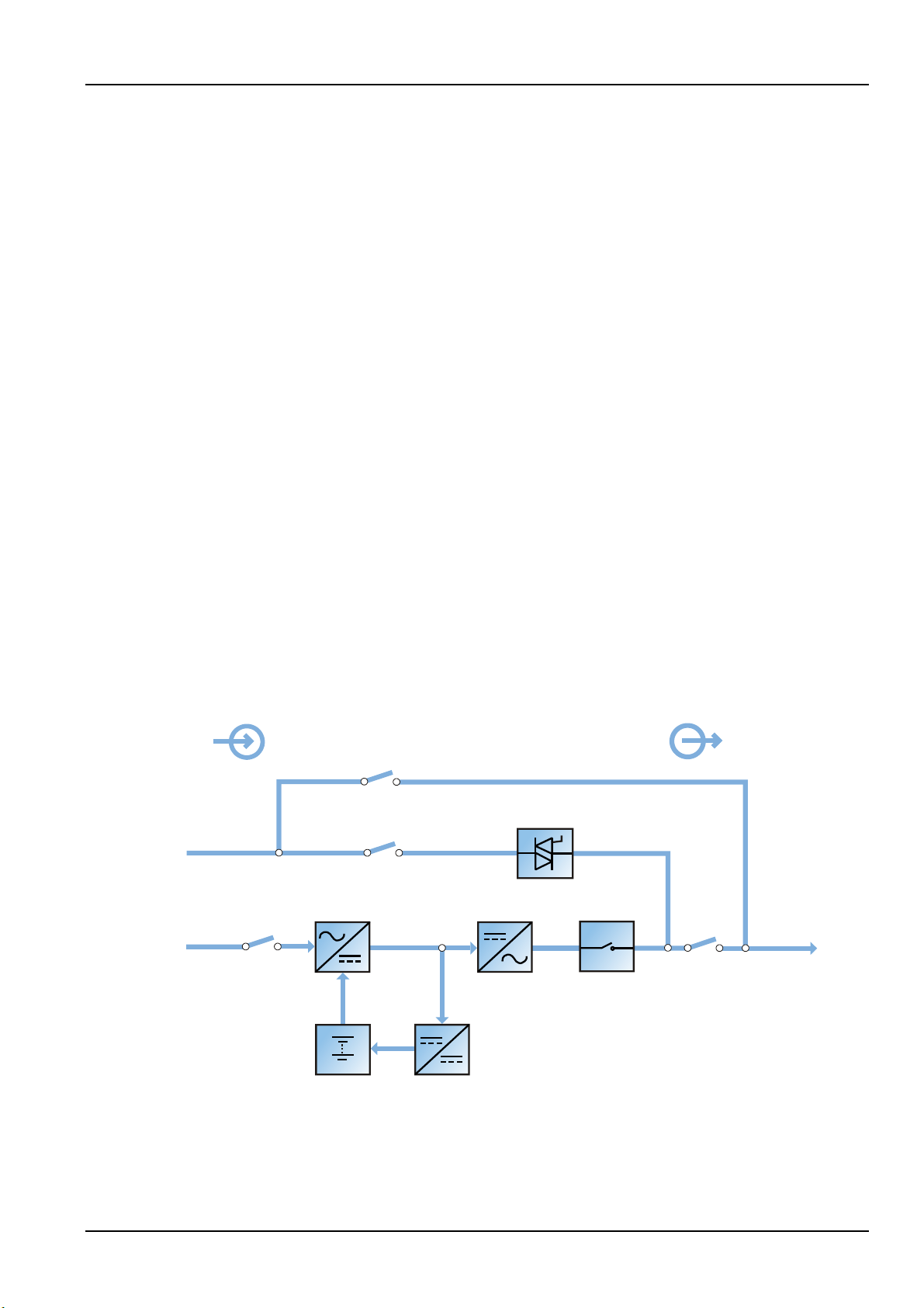
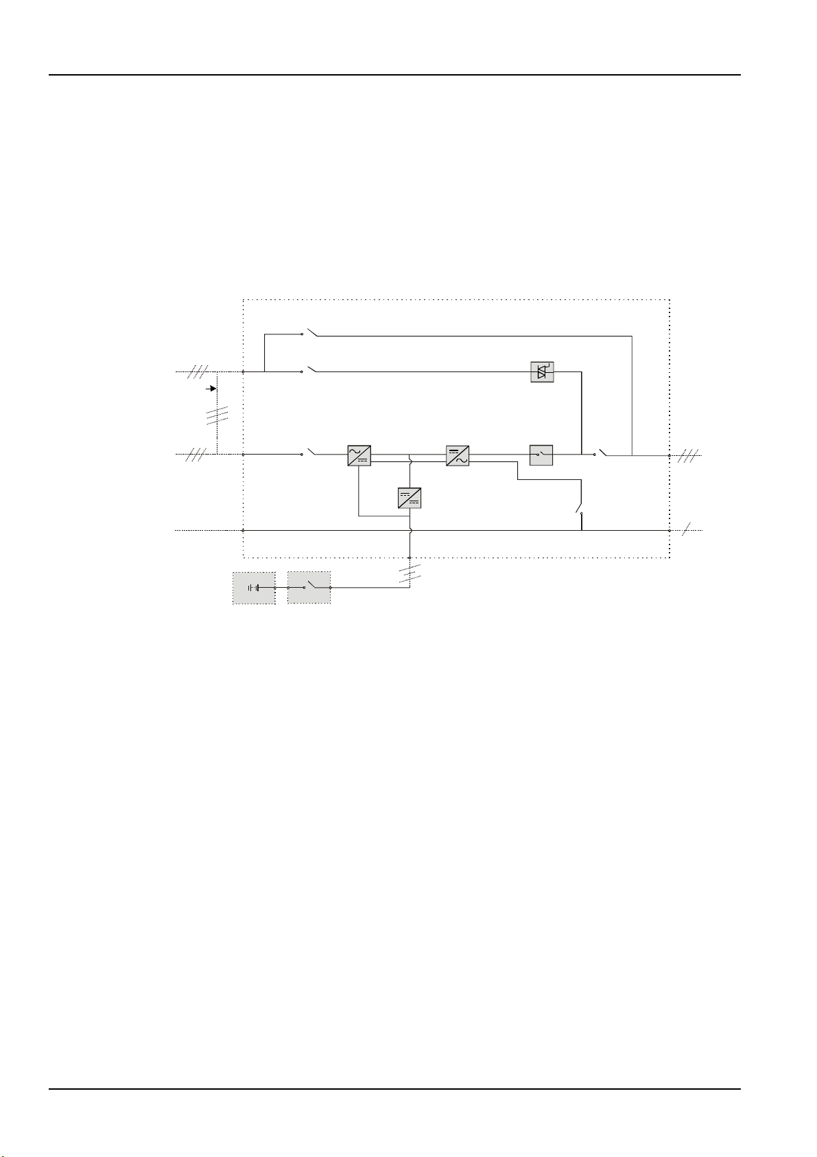
This section introduces the working principle of the single UPS module. The UPS adopts AC-DC-AC
converter (as shown in Figure 1-1). The first stage conversion (AC-DC) adopts three-phase high frequency
rectifier to convert the three-phase input voltage into stable DC bus voltage.
Figure 1-1 Block diagram for working principle of UPS single module
The UPS has its own battery charger and adopts advanced temperature compensation technology to
effectively prolong the battery service life. The inverter mainly adopts large power IGBT, and adopts
advanced SVPWM technology for control, to invert the DC bus voltage back to AC voltage.
Liebert NXC 60kVA UPS User Manual
Page 17
2 Chapter 1 Overview
Note
When the load is supplied by the bypass or maintenance bypass, the power quality & availability will be unregulated.
When the mains is normal, the rectifier and inverter work together to supply the loads and charge the
battery.
When the mains is abnormal, the rectifier stops working, and the battery supplies power to the loads
through the inverter. If the battery voltage falls to end of discharge (EOD) voltage and the mains still has
not been recovered, the UPS will shut down (if the system uses split bypass configuration and the bypass
is normal, the system will transfer to bypass). The battery EOD voltage is preset. When the mains is
abnormal, the battery maintains the UPS operation till the battery voltage is reduced to EOD voltage and
the UPS shuts down, this time is called 'Backup Time'. The length of backup time depends on the battery
capacity and the loads.
1.2.2 Bypass
Through the intelligent control of the 'Static Switch' module (as shown in Figure 1-1) containing the
controllable electronic switch, the loads can be supplied by the inverter or the bypass. In normal situation,
the loads are supplied by the inverter, in which case the automatic inverter switch at inverter side is
closed. In the case of overload (the overload delay time expires) or inverter failure, the inverter switch is
opened, and the 'Static Switch' module will automatically transfer the loads to the bypass.
In normal operating state, to realize the uninterrupted transfer between inverter and bypass, the inverter
output must be synchronized with the bypass.
Therefore, when the bypass frequency is within the synchronization range, the inverter control circuit will
synchronize the inverter output frequency with the bypass frequency and phase.
Besides, the UPS has a manual maintenance bypass switch for shutdown of the UPS upon maintenance. In
this situation, the bypass will directly supply the critical loads through the maintenance bypass.
1.2.3 System Control Principle
Normal operation
Normal mode: It means that the UPS has normal input mains, the rectifier and inverter operate normally,
the load is supplied by the inverter, the battery circuit breaker is closed, and the battery is in stable
floating charge state.
(Parallel System)
Note: As the UPS single module outputs are connected in parallel, the system checks
that the inverter control circuits are perfectly synchronized with one another and with the bypass in terms
of both frequency and phase, and that they have the same output voltages. Current supplied to the load is
automatically divided among UPSs. A warning message appears while synchronization is in progress.
Mains abnormal
When the mains fails or is abnormal, the rectifier will stop working automatically, and the system will
transfer to battery output (through inverter). The length of the operation time in battery mode depends
on the load and the battery capacity. During this period, if the battery voltage falls to the EOD voltage and
the mains still has not been recovered, the inverter will stop working automatically, and the UPS operator
control and display panel will display corresponding alarm messages. If the system uses split bypass
configuration and the bypass is normal, the system will transfer to bypass.
Liebert NXC 60kVA UPS User Manual
Page 18

Chapter 1 Overview 3
Warning
If the UPS system is composed of two or more UPS modules, and the load capacity exceeds the single module
Mains recovery
When the mains resumes normal within allowable time, the rectifier will start automatically (at this time its
output power will increase gradually) and supply the load and charge the battery again. Therefore, the
power supply to the load will not be interrupted.
Battery disconnection
To disconnect the external battery from the UPS system for maintenance, use the external isolation
device. At this time, except for the battery backup function upon mains failure, other functions and all the
steady state performance of the UPS will not be affected.
UPS module failure
In case of inverter failure, inverter switch failure, output fuse blowout and bypass STS failure, the load will
automatically transfer to the bypass, and the output power supply will not be interrupted. In this situation,
please contact the local customer service center of Vertiv Tech Co., Ltd for technical support.
(Parallel System)
In the event of a fault in a UPS module, it will automatically exit from the parallel system.
If the system is still capable of providing the required load, the remaining modules will continue to supply
the load with no interruption. If the remaining modules are no longer capable of fulfilling power
requirements, the load will automatically transfer to the bypass.
Overload
If the inverter is overloaded or the inverter current remains outside the specifications (refer to Table 11-6)
longer than the specified time, the load will automatically transfer to the bypass without power
interruption. If both the overload and the current are reduced to a level within the specified range, then
the load will be transferred back to the inverter. In case of output short circuit, the load will be transferred
to the bypass, and the inverter will shut down. Five minutes later, the inverter will start up automatically. If
the short circuit is removed at this point, the load will be transferred back to the inverter. The transfer is
determined first of all by the features of the protective device of the system.
In the above two situations, the UPS operator control and display panel will display alarm messages.
(Parallel System)
The control logic system constantly monitors load requirements and controls the power
supplied by each UPS module. In the event that an overload condition is sustained for greater than a
preset time, the load will transfer to the bypass, when the number of active modules is unable to satisfy
load requirements. The load returns to the inverter if the power is reduced to a value that can be
sustained by the number of active modules in the system.
Maintenance bypass
The UPS has a second bypass circuit, i.e. maintenance bypass, which provides a safe working environment
for the engineers to provide regular maintenance or repair to the UPS system and at the same time
provide unregulated mains supply to the loads. The maintenance bypass can be manually selected
through the maintenance bypass switch, and it can be disconnected by turning the switch to OFF.
capacity, do not use the internal maintenance bypass switch.
Liebert NXC 60kVA UPS User Manual
Page 19
4 Chapter 1 Overview
Bypass input
Mains input
Neutral line input
Battery
BCB
Rectifier
Inverter
Charger
DC bus
UPS
Maintenance bypass switch Q3
Bypass input switch Q2
Rectifier input
switch Q1
Static switch
Automatic
inverter switch
Output switch Q5
UPS output
Neutral line
output
Shorting copper
bar of common
input configuration
Neutral line
switch Q6
Neutral line
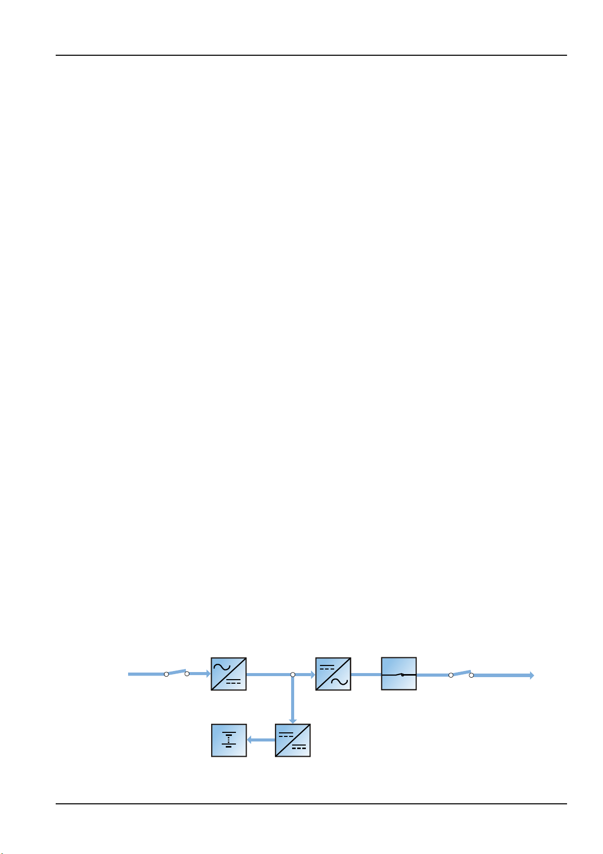
1.2.4 UPS Power Supply Switch Configuration
Figure 1-2 describes the block diagram of the UPS module. The UPS has split bypass configuration (that is,
the bypass adopts independent mains input) and common input configuration. In split bypass
configuration, the static bypass and maintenance bypass share the same independent bypass power
supply. Where a separate power source is not available, the input supply connections of the bypass input
switch (Q2) and rectifier input switch (Q1) would be linked together (linked before delivery) to make the
bypass input and rectifier input use mains power of the same route.
During the normal operation of the UPS, except for the maintenance bypass switch Q3, other switches
shall be closed.
1.2.5 Battery Circuit Breaker (BCB)
1.3 Parallel System
1.3.1 Parallel System Features
Figure 1-2 UPS power supply switch configuration
The external battery shall be connected to the UPS through the BCB. The BCB box is an option, which
shall be installed near the battery. The BCB is closed manually or electrically. The BCB has undervoltage
tripping coil. Upon battery undervoltage, the UPS control circuit will send a signal to the coil to trip the
BCB. It also has a magnetic trip facility for overload protection.
Up to four UPS modules can be parallel-connected to form a parallel system to increase the system
capacity and reliability. The load is equally shared between the paralleled UPS modules.
Moreover, two UPS modules or parallel system can comprise a dual bus system (LBS). Each UPS module
or parallel system has independent output. Output synchronization is achieved through the LBS cable,
thus enabling seamless load transfer between the two systems.
1. The hardware and software of parallel system are completely the same as those of the single module.
The parallel system configuration is achieved through settings in configuration software or panel buttons.
2. Parallel cables are connected in a ring, providing both system reliability and redundancy. LBS cables are
connected between any two UPS modules of each bus. The intelligent parallel logic provides the user with
Liebert NXC 60kVA UPS User Manual
Page 20
maximum flexibility. For example, shutting down or starting up UPS modules in a parallel system can be
Rectifier input switch
Mains input
Battery charger
Output switch
InverterRectifier
UPS output
Battery
Automatic inverter switch
done in any sequence. Transfers between normal mode and bypass mode of operation are seamless and
self-recoverable, that is, the overload is cleared, and the system will be automatically recovered to its
original operation mode.
3. The total load of the parallel system can be queried from each UPS module's LCD.
1.3.2 Parallel System Requirements
A group of paralleled modules behave as if it were one large UPS with the advantage of presenting higher
reliability. To ensure that all modules are equally utilised and to comply with relevant wiring rules, the
following requirements apply:
1. All UPS modules must be of the same rating and must be connected to the same bypass source.
2. The bypass and rectifier input sources must be connected to the same neutral line input terminal.
3. Any RCD, if installed, must be of an appropriate setting and located upstream of the common neutral
line input terminal. Alternatively, the device must monitor the protective earth current of the system. Refer
to Warning: high earth leakage current before Contents.
4. For parallel system consists of two or more UPS modules, the bypass load sharing inductors (optional)
should be selected.
Chapter 1 Overview 5
1.4 Operation Modes
The UPS has the following operation modes:
Normal mode
Battery mode
Automatic restart mode
Bypass mode
Maintenance mode
ECO mode
Parallel redundancy mode (system expansion)
LBS system mode
Common battery string mode
Frequency converter mode
Normal mode
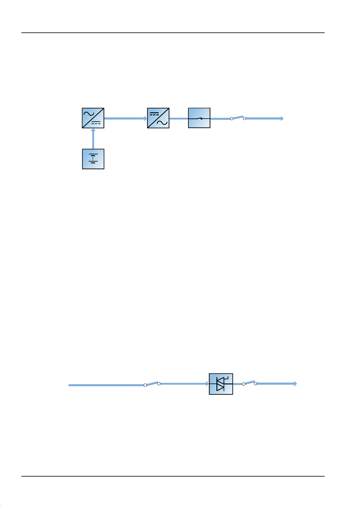
As shown in Figure 1-3, the mains is rectified by the UPS rectifier and then inverted by the inverter to
supply uninterrupted AC power to the loads. At the same time, the charger will charge the battery.
Figure 1-3 Schematic diagram of normal mode
Liebert NXC 60kVA UPS User Manual
Page 21
6 Chapter 1 Overview
Output switch
InverterRectifier
UPS output
Battery
Automatic inverter switch
Bypass input switch
Bypass input
Static switch
Output switch
UPS output
Battery mode
As shown in Figure 1-4, the operation mode in which the battery provides backup power supply to the
loads through the rectifier and inverter is called battery mode. Upon mains failure, the system will
automatically transfer to the battery mode with no load power interruption. When the mains is recovered,
the system will automatically transfer back to the normal mode without any manual intervention, and the
power to the load will not be interrupted.
Note: Battery cold start function is available for switching on the UPS from Battery (charged) mode directly
during mains failure. Therefore, the battery power supply can be used independently to improve the availability
of the UPS.
Figure 1-4 Schematic diagram of battery mode
Automatic restart mode
The UPS has automatic restart function. When the inverter shuts down because the mains fails and the
battery discharges to EOD voltage, if the mains is recovered, the UPS will restart automatically after a
certain time of delay. This function and the automatic restart type can be set by the service engineer
authorized by Vertiv.
During the process of automatic restart time of delay, the UPS will charge the battery to protect against
the power-off risk of the load device caused by mains power failure.
If the automatic restart function has not been set, the user can manually start the UPS through pressing
the FAULT CLEAR key first and ON key next.
Bypass mode
As shown in Figure 1-5, in normal mode, in case of inverter failure, inverter overload or inverter manual
shutdown, the static switch will transfer the load from the inverter side to bypass side, with no interruption
in power to the load. At this time, if the inverter and bypass are not synchronized, the power of the load
has transitory interruption, with time of less than 20ms.
Figure 1-5 Schematic diagram of bypass mode
Maintenance mode
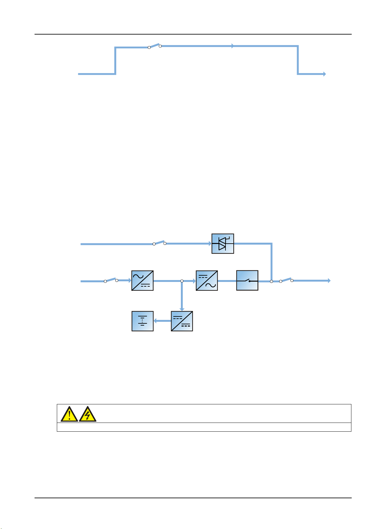
As shown in Figure 1-6, if the UPS maintenance or service is required, you may use the manual
maintenance bypass switch to transfer the load to maintenance bypass, with no interruption in power to
the load. This maintenance bypass switch is fitted in all UPS modules and rated for full load of one module.
Liebert NXC 60kVA UPS User Manual
Page 22
Chapter 1 Overview 7
Maintenance bypass switch
Bypass input
Maintenance bypass
UPS output
Bypass input switch
Rectifier input switch
Bypass input
Mains input
Battery charger
Output switch
InverterRectifier
Static switch
UPS output
Battery
Automatic
inverter switch
Warning
The load is not protected against distortion on the mains voltage waveform in ECO mode.
Figure 1-6 Schematic diagram of maintenance mode
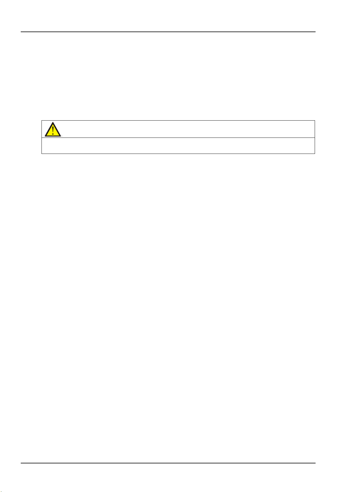
ECO mode
If ECO mode is selected, the double-conversion UPS operation is inhibited most of time for the purpose of
saving energy. In this mode, the bypass is the preferred source and only when the voltage and/or
frequency of the bypass supply are/is beyond the pre-defined threshold the critical AC load is transferred
to the inverter: if the inverter is synchronized with the bypass source, the transfer will be instantaneous
and during the transfer the output waveform will not exceed the limits set by IEC/EN 62040-3 for a UPS
to be classified as VFI-SS-111.
If the inverter is not synchronized with the bypass, in order to avoid hazardous cross current,
bypass/inverter changeover is triggered only after a few milliseconds (max. 20ms) from when bypass has
been disconnected from the load. Then, after bypass frequency and voltage have came back and
remained within the predefined limits for at least five minutes, the load is automatically and
instantaneously transferred back to bypass source.
In this mode, the system can normally charge the battery.
Figure 1-7 Schematic diagram of ECO mode
If ECO mode is required, adjust the corresponding parameters through the operator control and display
panel.
The operation method of ECO mode is the same as the description in Chapter 5 UPS Operation
Introduction. However, in normal mode, the load is powered by the bypass, the inverter indicator is
flashing, and the LCD displays 'Bypass mode', and the transfer interval time is less than 20ms.
Parallel redundancy mode (system expansion)
For higher capacity or higher reliability or both, the outputs of multiple UPS modules can be programmed
for directly paralleling while a built-in parallel controller in each UPS module ensures automatic load
sharing. The parallel system can be composed of up to four UPS modules. For the operation principle
diagram of the parallel redundancy mode, see Figure 7-1.
Liebert NXC 60kVA UPS User Manual
Page 23
8 Chapter 1 Overview
Note
The batteries of different manufacturers, different types and different capacities are not allowed to be used
LBS mode
A dual bus system consists of two independent UPS systems, each containing one or more parallel UPS
modules. The dual bus system has high reliability and is suitable for load with multiple inputs. For
single-input load, an STS can be installed to power the load. For the operation principle diagram of the
LBS mode, see Figure 7-4 and Figure 7-5.
Common battery string mode
It means that when the UPS modules (up to four UPSs) are connected in parallel, each UPS module can
use the same battery string to achieve the aim of cost-saving and clearance-saving.
together. The common battery string mode is suitable for parallel system only, and does not support the LBS mode.
Frequency converter mode
The UPS can be programmed into frequency converter mode for either 50Hz or 60Hz stable output
frequency. The input frequency may vary from 40Hz to 70Hz. Under this mode, it is required to open the
maintenance bypass switch to disable the static bypass operation, and the battery becomes optional
depending on any requirement to operate in battery mode.
1.5 Battery Management
The following battery management functions are set by the service engineer through the Vertiv setting
software.
1.5.1 Normal Function
1. Constant current boost charge
Adopt the constant current (within battery charging limit) to charge the battery. The function can be used
for battery capacity fast recovery. The charge current can be set.
2. Constant voltage boost charge
Adopt the constant voltage to charge battery. The function can be used for battery capacity fast recovery.
For VRLA batteries, the maximum boost charge voltage should not exceed 2.4V/cell.
3. Float charge
The charging method is used for keeping battery with a full capacity. The float charge voltage is generally
low. The function can balance the capacity loss due to battery self discharging, and can be used for
battery capacity recovery.
For VRLA batteries, the float charge voltage should be between 2.2V/cell and 2.3V/cell.
4. Automatic transfer to float charge
When the charge current is less than 'Threshold of Equalize Charge to Float Charge' or 0.5A, the charger
will automatically transfer from boost charge to float charge. When boost charge time exceeds the limit of
'Equalize Charge Protect Time Limit', the charger will be forcibly transferred to float charge for protecting
the battery.
5. Float charge temperature compensation (optional)
This function must be used together with the battery temperature detection device. The Vertiv battery
temperature sensor is a standard option for your selection.
Liebert NXC 60kVA UPS User Manual
Page 24

6. EOD protection
When the battery voltage drops to the EOD voltage, the battery converter shuts down automatically and
the battery is isolated to avoid further battery discharge. The EOD voltage is settable from 1.6V/cell to
1.85V/cell (VRLA).
7. Battery low pre-warning time
The battery low pre-warning time is adjustable between 3min and 60min. The default setting is 5min.
8. Maximum battery discharge time
When the battery has small current discharge for a long time, the battery is over discharged and even has
unrecoverable damage, thus setting a battery discharge time to protect the battery is essential. The limit
of time setting shall be configured by service engineer through the Vertiv setting software.
9. Maximum boost charge protection time
To protect against the battery overcharge damage caused by long time boost charge, a protect time
setting is essential. The limit of time setting shall be configured by service engineer through the Vertiv
setting software.
1.5.2 Advanced Function
The UPS provides battery maintenance test function. At periodic intervals, 20% of the rated capacity of
the battery will be discharged automatically, and the actual three-phase load must exceed 20% of the
nominal UPS capacity. If the load is less than 20%, the automatic discharge cannot be executed. The
periodic interval can be set from 30 to 360 days. The battery maintenance test function can be disabled
through the Vertiv setting software.
Chapter 1 Overview 9
Conditions: Battery at float charge for at least 5h, load equal to 20% ~ 100% of rated UPS capacity.
Trigger: Automatically, or manually through the command of battery maintenance test in LCD.
Interval: 30 ~ 360 days (default setting: 60 days).
The UPS also provides battery capacity self-test function: Periodically test the battery activity, test the
battery residual capacity, judge the battery quality, and then provide the corresponding measures. The
capacity self-test is started by the user through the operator control and display panel. During the
capacity self-test, the battery will continuously discharge to the battery undervoltage shutdown threshold.
After the self-test is finished, the system will update the battery curve table. The capacity self-test
command is valid only one time, without any memory. During the capacity self-test, if the battery
maintenance requirement is satisfied, the system will generate audible/visual alarm and give
corresponding records.
Conditions: System load rate within 20% ~ 100%, battery float charge at least 5h, and generator not
connected; the current system is in float charge state.
Trigger: Start up through the LCD.
Note:
1. The battery will continuously discharge to the battery undervoltage shutdown threshold, then the
battery transfer to the charging state. When the capacity self-test is finished, the system will update the
battery curve table.
2. The user can manually stop the capacity self-test operation through the LCD.
Liebert NXC 60kVA UPS User Manual
Page 25

10 Chapter 1 Overview
1.5.3 Battery Temperature Compensation
The UPS system has battery charge temperature compensation function. When the ambient temperature
is increased, the DC bus voltage (which charges the battery) will be reduced correspondingly to provide
optimal charging voltage for the battery, thus prolonging the battery service life time.
This function must be used together with the Vertiv battery temperature detection device (a standard
option).
1.6 Battery Protection
The following battery protection functions are set by the service engineer through the Vertiv setting
software.
Battery low pre-warning
The battery low pre-warning occurs before the EOD. After this pre-warning, the battery should have the
capacity for three remaining minutes discharging with full load. The time can be configured from 3min to
60min.
EOD protection
When the battery voltage drops to the EOD voltage, the battery converter shuts down automatically. The
EOD voltage is adjustable from 1.6V/cell to 1.85V/cell (VRLA).
BCB alarm
The BCB alarm occurs when the external BCB opens, if you select the Vertiv BCB (optional).
The external battery connects to the UPS through the BCB. The BCB is manually closed and tripped by
the UPS control circuit.
Liebert NXC 60kVA UPS User Manual
Page 26
Chapter 2 Mechanical Installation
Warning: professional installation required
1. Do not disassemble the package without permission of authorized service engineer.
Warning: battery danger
Take special care when installing batteries. When connecting batteries, the battery terminal voltage will reach
This chapter briefly introduces the mechanical installation of the UPS, including the precautions, initial
inspection before installation, environmental requirement, mechanical requirement and installation
diagram.
2.1 Precautions
This chapter describes the environmental and mechanical requirements and mechanical considerations
that must be taken into account when planning the positioning and cabling of the UPS equipment.
Because each site has its particular characteristic, this chapter does not provide the detailed installation
steps, it only acts as a guide for the general procedures and practices that should be observed by the
installing engineer, so that they can properly handle the specific situation of the site.
Chapter 2 Mechanical Installation 11
2. The UPS should be installed by an authorized engineer in accordance with the information contained in this
chapter.
320Vdc, which is fatal to human being.
1. Please wear safety glasses to protect the eyes from being damaged by arc.
2. Remove all the metal items, including finger rings, watch, etc.
3. Use tools with insulated handle.
4. Wear rubber gloves.
5. If the battery has electrolyte leakage or the battery is damaged, it must be replaced. Place the battery into the
container that can withstand sulfuric acid and dispose of it according to the local regulations.
6. If the skin contacts the electrolyte, flush it with water immediately.
2.2 Transportation
Railroad transportation and shipping are the recommended means of transportation. If truck
transportation is unavoidable, choose roads that are less bumpy in order to protect the equipment.
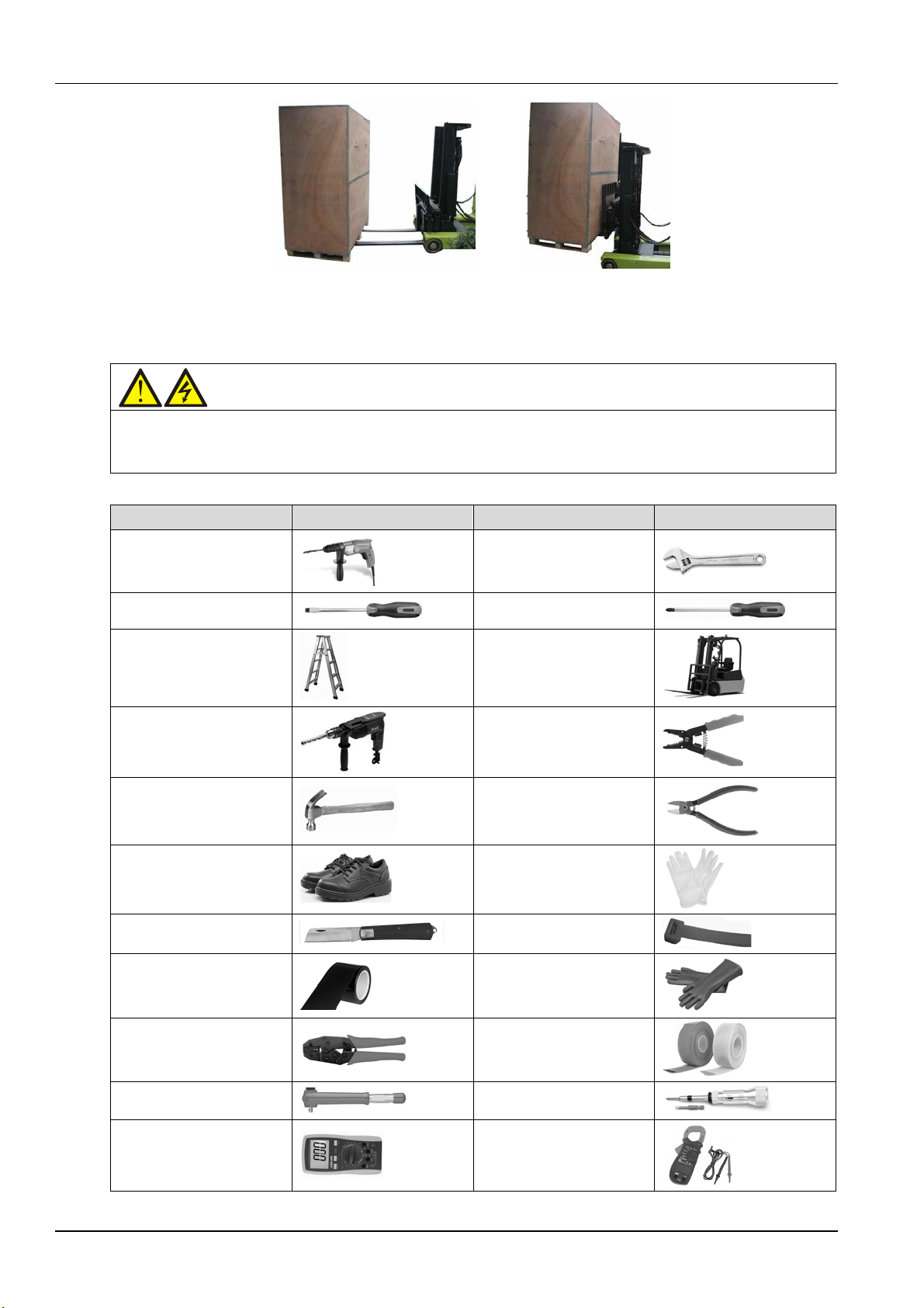
The UPS cabinet is heavy (see Table 11-3 for the weight). It is recommended to use mechanical
equipment such as an electric forklift to unload and move the equipment to the place closest to the
installation site. If an electric forklift is used, insert the tines of the forklift below the bottom pallet (as
shown in Figure 2-1) to prevent the equipment from falling over.
Liebert NXC 60kVA UPS User Manual
Page 27
12 Chapter 2 Mechanical Installation
Warning
1. For the sake of safety, the installation tools under live operation must be insulated.
Name
Drawing
Name
Drawing
2.3 Tools
2. Tools in Table 2-1 are for reference only; please follow the actual requirement for on-site installation and
connection.
Figure 2-1 Inserting and movement
Table 2-1 Tools
Electric hand drill
Slotted screwdriver
Stepladder
Drill
Claw hammer
Insulating shoes
Electrician knife
Insulating tape
Adjustable wrench
Cross head screwdriver
Forklift
Wire cutting plier
Diagonal cutting plier
Antistatic gloves
Cable tie
Insulating gloves
Crimping plier
Insulated torque wrench
Multimeter
Liebert NXC 60kVA UPS User Manual
Heat shrinkable tube
Torque screwdriver
Clip-on ammeter
Page 28
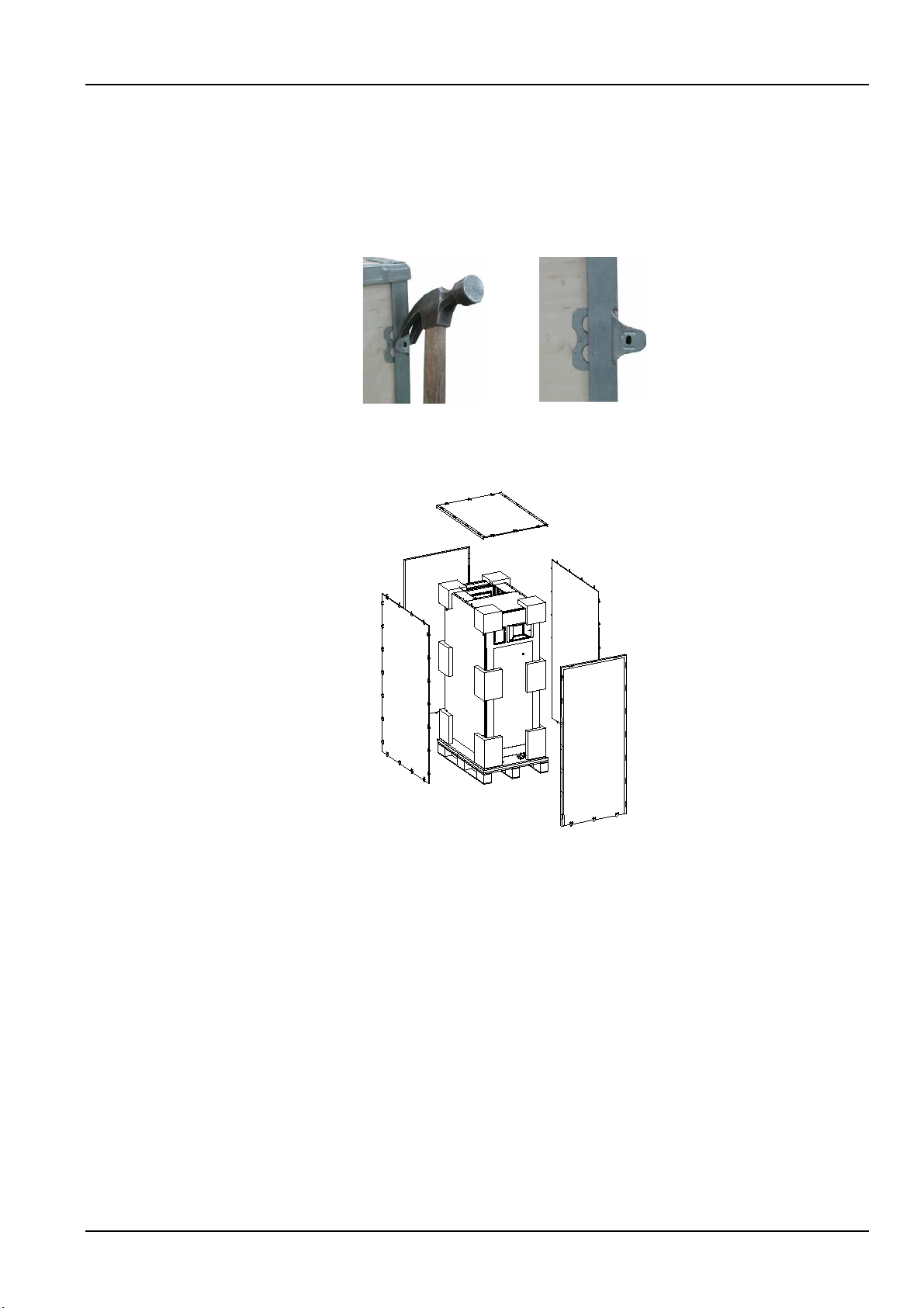
2.4 Unpacking
I
I
II
II
III
Unpack the UPS and battery packages under the guidance of authorized service engineer. Steps:
1. Remove the side panels and top cover.
Use a hammer or straight screwdriver to straighten the connection hook that connects the side panels to
the top cover, as shown in Figure 2-2.
At first, straighten all the hooks that fix side panel I, and remove side panel I. Then straighten all the hooks
that fix side panel II, and remove side panel II. At last remove top cover III, as shown in Figure 2-3.
Chapter 2 Mechanical Installation 13
Figure 2-2 Straightening the hook
Figure 2-3 Removing side panels and top cover
2. Remove the fixing bolts of the bottom pallet (see Figure 2-4), and reserve the fixing bolts. Then use the
forklift (following the inserting direction shown in Figure 2-4) to move the cabinet near the installation
place.
Liebert NXC 60kVA UPS User Manual
Page 29
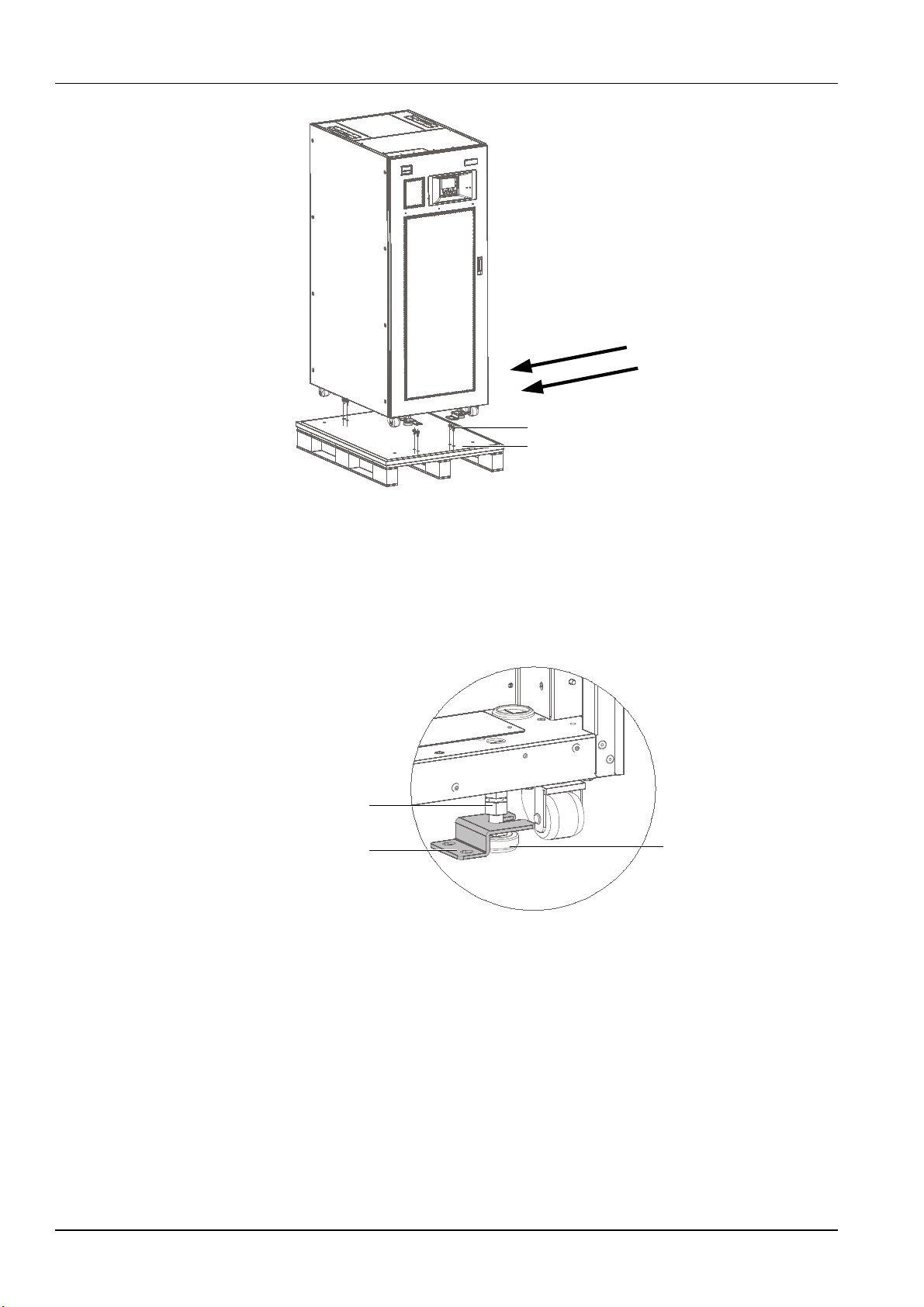
14 Chapter 2 Mechanical Installation
Inserting direction
Fixing bolt
Bottom pallet
Nut
Foot fixing piece
Foot
Foot fixing piece
Figure 2-4 Removing bottom pallet
3. After moving the cabinet to the installation place, you should raise the four adjustable feet, and then use
the castors to move the cabinet to its final installation site.
Method of raising one foot: as shown in Figure 2-5, first loosen the nut (installed in factory) from bottom to
top, and remove the foot fixing piece (reserve it), then rotate the foot to raise it for avoiding affecting the
slide of the castor.
Figure 2-5 Schematic diagram for raising the foot
2.5 Initial Inspection
Before installing the UPS, carry out the following inspections:
1. Ensure that the environment of the UPS equipment room meets the environmental requirement
specified in the product technical specifications, especially the ambient temperature, ventilation
conditions, and the dust situations.
2. Unpack the UPS and battery under the guidance of authorized service engineer. Visually inspect
whether the inside and outside of the UPS and battery have any transportation damage. If there is any
damage, report to the carrier immediately.
Liebert NXC 60kVA UPS User Manual
Page 30

3. Verify the UPS label and confirm the correctness of the UPS. The UPS label is attached on the back of
Warning
the door. The UPS model, capacity and main parameters are marked on the label.
2.6 Environmental Requirement
2.6.1 UPS Location Selection
The UPS should be located in a cool, dry, clean-air indoor environment with adequate ventilation, and
should be located on concrete or other nonflammable and flat surfaces. The ambient environment should
be free of conductive powder (such as metallic powder, sulfide, sulfur dioxide, graphite, carbon fiber,
conductive fiber, etc.), acid mist or other conductive media (strongly ionized substances). The
environment specifications should comply with relevant international standard & specifications and the
operating range (see Table 11-2) specified in this manual.
The UPS uses forced cooling by internal fans. Cooling air enters the UPS through the ventilation grills at
the front of the cabinet and exhausted through the ventilation grills at the back of the cabinet. Do not
obstruct the ventilation holes (ventilation grills). The rear of the UPS should be kept a distance at least
200mm from the wall to avoid blocking the UPS heat dissipation, thus reducing the UPS internal
temperature and improving the UPS life.
Chapter 2 Mechanical Installation 15
If necessary, install indoor extractor fans to aid cooling-air flow to avoid room temperature buildup. Air
filters (optional) should be used when the UPS is to operate in a dirty environment.
Note 1: When the battery cabinet is installed near the UPS, the maximum allowable ambient
temperature is dependent on the battery rather than the UPS.
Note 2: If the UPS is working in ECO mode, the power consumption will be less than that in Normal
mode. Proper air conditioning system shall be selected according to the normal operating mode.
2.6.2 Battery Location Selection
Batteries generate some amount of hydrogen and oxygen at the end of charge, so the fresh air volume of
the battery installation environment must meet the EN50272-2001 requirements.
The ambient temperature is the main factor that affects the battery capacity and life. The normal
operating temperature of the battery is 20°C. If the ambient temperature is higher than 20°C, the battery
life will be reduced. If it is lower than 20°C, the battery capacity will be reduced. In normal situation, the
allowable ambient temperature for the battery is 15°C to 25°C. The ambient temperature of the battery
shall be maintained constant, and the battery shall be kept away from heat source and air outlet.
Battery can be installed inside the specialized battery cabinet which shall be close to the UPS. If the
battery is placed on the raised floor, bracket shall be installed under the floor, just as for the UPS. If the
battery adopts rack mounting or is mounted far from the UPS with other installation mode, the battery
circuit breaker shall be installed near the battery, and the cabling distance shall be minimized.
2.6.3 Storage
Should the UPS not be installed immediately, it must be stored with the original packaging in a room for
protection against excessive humidity and heat sources (see Table 11-2). The battery needs to be stored
in a dry and cool place with good ventilation. The most suitable storage temperature ranges from 20°C to
25°C.
Liebert NXC 60kVA UPS User Manual
Page 31
16 Chapter 2 Mechanical Installation
During battery storage, periodically charge the battery according to the battery manufacturer instructions. In the
Warning
1. The lifting equipment for moving the UPS cabinet shall have enough lift capacity.
Caution
Take special care when moving the battery cabinet fitted with batteries, in which case, you must fasten each
charge process, temporarily connect the UPS to the mains and activate the battery by recharging the battery.
2.7 Mechanical Requirement
2.7.1 Moving Cabinet
2. The UPS has installed castors. When removing the UPS from the shipping pallet, pay attention to keeping the
UPS from sliding. Ensure that adequate personnel and lifting equipment are available when removing the shipping
pallet.
3. Due to its intensity, the castors may be valid only on the flat surface.
4. The center of gravity of the UPS cabinet is high, avoid falling over during the cabinet movement.
5. Vertical hanging of cabinet is not allowed.
battery string, and try to minimize the movement distance.
Ensure that the UPS weight does not exceed the capacity of the lifting equipment. For the UPS weight,
refer to Table 11-3.
The UPS cabinet can be moved by forklift or other similar lifting equipment.
For short distance movement, the castors can be used.
2.7.2 Clearance
Because the UPS has no grill at the two sides, there is no special clearance requirement on the two sides.
Besides the local regulations, to enable routine tightening of the power terminals within the UPS, it is
recommended that clearance around the front of the UPS should be at least 1200mm to achieve easy
operation and service. Meanwhile, maintain at the back of the cabinet a clearance at least 200mm to
permit adequate circulation of air coming out of the UPS.
2.7.3 Cable Access Mode
The UPS adopts top cable access method and bottom cable access method.
For details, refer to 3.1.10 Power Cable Connection Steps and 3.2.11 Signal Cable Connection Steps.
2.7.4 Final Positioning And Fixing
After the final positioning of the UPS, use the four adjustable feet to fix the UPS on the floor, as shown in
Figure 2-6. Method:
1. Loosen the nuts from bottom to top.
2. Rotate the feet down to touch the floor.
3. Plug the foot fixing pieces to the feet.
4. Align the foot fixing pieces with the installation holes dug according to dimensions shown in Figure 2-7.
Liebert NXC 60kVA UPS User Manual
Page 32

Chapter 2 Mechanical Installation 17
Nut
Installation hole
FootFoot fixing piece
5. Rotate the nuts from top to bottom till the nuts firmly press the foot fixing pieces, and then use the
fixing bolts M10 to fix the UPS on the floor.
Figure 2-6 Schematic diagram for UPS positioning and fixing
Liebert NXC 60kVA UPS User Manual
Page 33

18 Chapter 2 Mechanical Installation
2.8 Installation Drawings
Figure 2-7 describes the key mechanical characteristics of the UPS.
Liebert NXC 60kVA UPS User Manual
Page 34
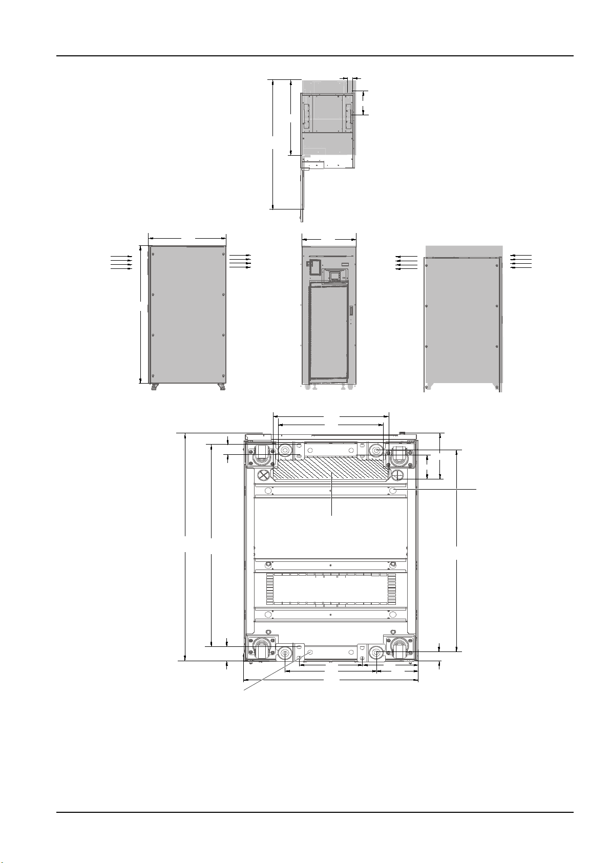
46
Ф
Ф
833
1433
262
Top view (door open)
Air
inlet
Air
outlet
Left side view
600
860
Air
inlet
Air
outlet
Right side view Front view
395
363
40
860 764
Cable access area
170
84
764
36 signal cable inlet
55
218
314
600
192
143
35
11 foot installation hole
Bottom view
1528
Chapter 2 Mechanical Installation 19
Figure 2-7 Top/front/side/bottom view of the UPS (unit: mm)
Liebert NXC 60kVA UPS User Manual
Page 35
20 Chapter 3 Electrical Installation
Warning
1. Do not power on the UPS before the arrival of authorized service engineer.
UPS power
(kVA )
Rated current (A)
Bus stud bolt/nut specification
Max.
input
Output/bypass
current2 at full load
Battery discharge
current (+, -, N) at
Input/battery/
output/
Recommended
torque (N.m)
Chapter 3 Electrical Installation
This chapter mainly introduces the electrical installation of the UPS, including the power cable and signal
cable connecting procedures and methods.
After completing the mechanical installation of the UPS, it is required to connect the power cable and
signal cable of the UPS. All the signal cables, whether shielded or not, shall be kept away from the power
cables.
2. The UPS cables should be routed by an authorized engineer in accordance with the information contained in this
chapter.
3.1 Wiring Of Power Cable
3.1.1 System Configuration
The cable size of the system power cable shall meet the following requirements:
UPS input cable
The cable size of the UPS input cable differs with the UPS power ratings and input AC voltages, provided
that it meets the requirement of maximum input current, including the maximum battery charge current,
see Table 3-1.
UPS bypass and output cable
The cable size of the UPS bypass and output cable differs with the UPS power rating and output AC
voltages, provided that it meets the requirement of nominal output or bypass current, as shown in Table
3-1.
Battery cable
Each UPS connects to its battery through the three cables connecting to the positive pole, negative pole
and neutral line. The cable size of the battery cable differs with the UPS power ratings, provided that it
meets the battery discharge current requirement when the battery discharges to near EOD voltage, as
shown in Table 3-1.
3.1.2 Maximum Steady State AC And DC Currents
The power cable must be selected according to the current and voltage values in Table 3-1 as well as the
local wiring regulations, and take environmental conditions (temperature and physical media) into
consideration, then refer to Table 3B in IEC 60950-1.
Table 3-1 Max. steady state AC and DC currents
Liebert NXC 60kVA UPS User Manual
Page 36

Chapter 3 Electrical Installation 21
current
1,2
380V
400
V
415V
min. battery voltage
bypass cable
M6/M8/M6/M
Model
Input
Output
Bypass
Neutral line
Earth cable
Battery
60kVA (3-in 3-out)
25
25
25
35
25
50
Model
Input port
Recommended
capacity of input
external switch
BCB
Output port
Recommended
capacity of output
external switch
60kVA (3-in
125A (3P), bypass
Terminal
60 (3-in 3-out ) 103 91 87 84 195/195/59
When selecting the battery cables, a max. volt drop of 4Vdc is permissible at the current ratings given in Table 3-1. Do
not form coils, so as to minimize the formation of EMI.
1. Input mains current for rectifier and bypass.
2. Non-linear load (like switch power) affects the design of output and bypass neutral line. The neutral line current
may exceed the rated phase current, at most 1.5 times of the rated phase current.
3.1.3 Recommended CSA Of UPS Cable
The recommended CSA of the UPS cable is listed in Table 3-2.
Table 3-2 Recommended CSA of the UPS cable (unit: mm2, ambient temperature: 25°C)
1. If the user’s cable CSA exceeds the value recommended in Table 3-2, or the harder cable installation is difficult,
please contact Vertiv service engineers.
2. If using top cable access method, the multi-core soft cable is recommended for convenient installation and wiring.
6
4.8/12/4.8/4.8
3.1.4 Selection Of UPS I/O Switch
Table 3-3 is the recommended UPS I/O switch capacity, and the user can select it according to actual
needs.
3-out)
1. To avoid the bypass switch misoperation due to surge current generated by output transformer power-on or
switching, it is recommended to set the bypass switch momentary current is 1250A or above.
2. The BCB option provided by Vertiv has the protection function of overload and short circuit, and it can also
automatically trip the battery switch to protect the battery and UPS when the battery at EOD point, faults like bus
voltage abnormal, battery over-temperature or over-voltage. Thus it is strongly recommended to use the BCB option
from Vertiv. If the user configures the BCB, the momentary current features and parameters should be set according
to the actual battery model and battery distribution system, and also adjust them according to the change of battery
internal resistance.
Terminal block
Table 3-3 Selection of the UPS I/O switch
125A (3P)
DC 200A (4P)
blcok
125A (3P)
3.1.5 Distance Between The UPS Connection Point And The Floor
See Table 3-4 for details.
Liebert NXC 60kVA UPS User Manual
Page 37
22 Chapter 3 Electrical Installation
UPS connection point
Min. distance(mm)
60kVA
Rectifier input
236
Bypass input
236
AC Output
236
Battery
265
PE terminal
220
Warning
Failure to ground as required can cause EMI, electric shock or fire risk.
Table 3-4 Min. distance between UPS connection point and floor
3.1.6 Notes
The following points are for general guidance only. If there are relevant local regulations, the local
regulations shall prevail.
1. The cable size of the neutral line shall be selected according to 1.5 times of the output/bypass phase
current.
2. The cable size of the protective earth cable shall be selected according to the AC power failure level,
cable length and protection type. The grounding wire connection must use the shortest connection route.
3. For the cables with large current, parallel connection of small cables can be adopted to facilitate the
installation.
4. When selecting the battery cable size, the current value in Table 3-1 shall be referred to, and a
maximum voltage drop of 4Vdc is allowed.
5. Do not form coils, so as to minimize the formation of EMI.
3.1.7 Power Cable Connecting Terminal
The rectifier input, bypass input, output and battery power cables are connected to the corresponding
terminals shown in Figure 3-2.
3.1.8 Protection Ground
The protective earth cable is reliably connected to the PE input terminal (see Figure 3-2) through the
fixing bolt. All the cabinets and cable troughs shall be grounded according to the local regulations. The
grounding wires shall be tied up reliably to prevent the loosening of the grounding wire tightening screws
when the grounding wires are pulled.
3.1.9 External Protective Device
To ensure the safety, it is necessary to install external circuit breaker for the input and battery of the UPS.
Because of the difference of the specific installations, this section only provides general practical
information for the installation engineer. The qualified installation engineer should have the knowledge of
the local wiring regulations on the equipment to be installed.
Rectifier and bypass input power supply
1. Input overcurrent and short circuit protection
Liebert NXC 60kVA UPS User Manual
Page 38
Chapter 3 Electrical Installation 23
Note
The rectifier input and bypass input must use the same neutral line.
Install suitable protective devices in the distribution line of the incoming mains supply. The protective
devices should provide functions such as the overcurrent protection, short circuit protection, isolation
protection and tripping upon backfeed. When selecting the protective devices, consider the power cable
current-carrying capacity, system overload capacity (see Table 11-6 and Table 11-7) and the short circuit
capability of the upstream power distribution. It is generally recommended to use the thermomagnetic
circuit breaker of IEC60947-2 tripping curve C (normal), when the current value reaches 125% of the
current value listed in Table 3-1.
2. Split bypass configuration
If the UPS adopts split bypass configuration, independent protective device shall be installed respectively
on the rectifier input and bypass input distribution lines.
3. Ground fault protection
If the pre-stage input power supply has an RCD, the transient state and steady state ground leakage
current upon the startup of the UPS shall be considered.
The RCCB shall meet the following requirements:
Be sensitive to the DC unidirectional pulse (class A) of the whole distribution network
Be insensitive to transient state current pulse
Have an average sensitivity which is 0.3A ~ 3A adjustable
The RCCB symbols are shown in Figure 3-1.
Figure 3-1 RCCB symbols
The UPS has an internal EMC filter, therefore the protective earth cable has leakage current which is
0 ~ 1000mA. It is recommended to confirm the RCD sensitivity of the upstream input distribution and the
downstream distribution (to the load).
External battery
The BCB is useful for protecting the external battery. The UPS requires an optional BCB box to provide
overcurrent protection, short circuit protection and automatic tripping functions for the external battery.
The rated voltage of the BCB is 500Vdc, and its DC breaking current is 20kA.
This BCB is important for the battery maintenance, and is generally installed near the battery.
System output
The UPS output distribution shall be configured with a protective device. The protective device shall be
different from the input distribution protection switch and able to provide overload protection (refer to
Table 11-6 and Table 11-7).
3.1.10 Power Cable Connection Steps
For cable access mode of the UPS, refer to 2.7.3 Cable Access Mode.
Liebert NXC 60kVA UPS User Manual
Page 39
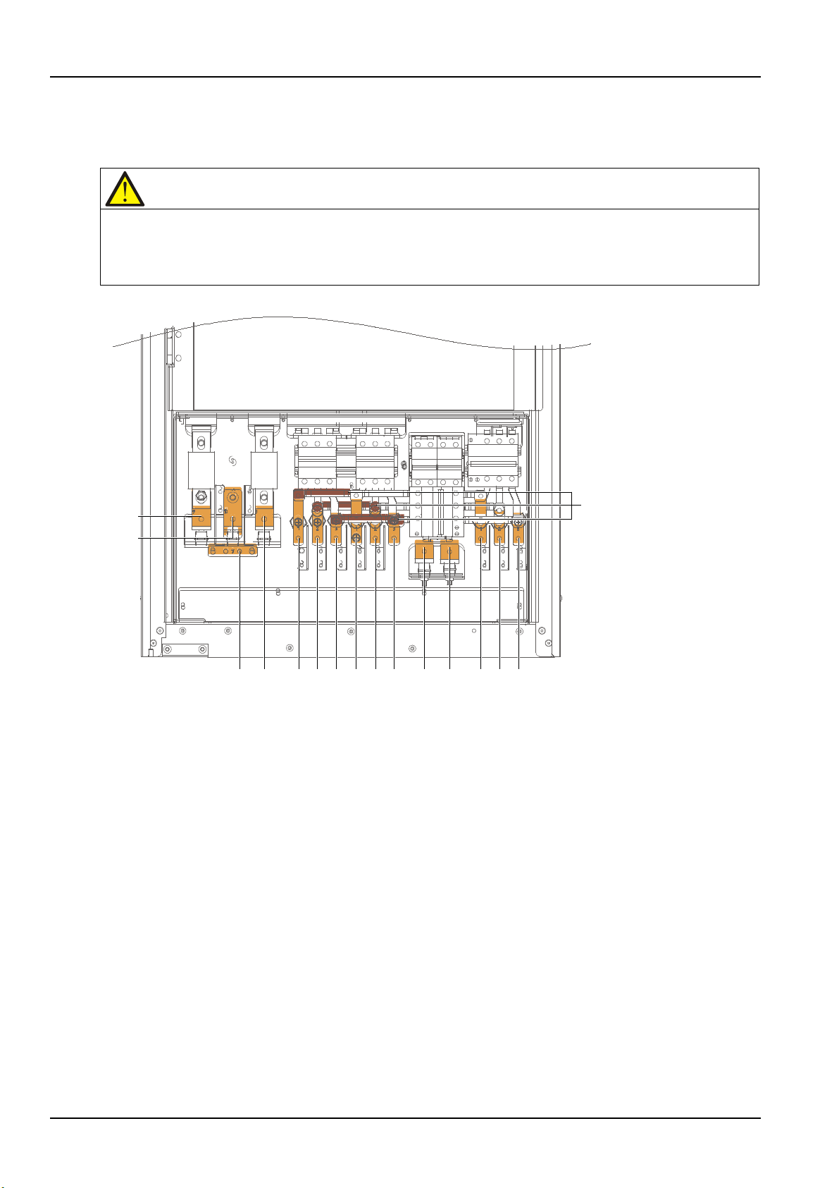
24 Chapter 3 Electrical Installation
Note
1. The power cables should be routed through tunnels or cable troughs to prevent cable damage due to mechanical
+
N
Shorting copper bar of
common input configuration
PE - mA mB mCbA bB bC N oN oA oB oC
Note:
1. +,-,N:battery input terminals
2. PE:PE inputterminal
3. mA, mB, mC: rectifer input terminals
4. bA, bB, bC, N:bypass input terminals
5. oA, oB, oC, oN: output terminals
1. +, -, N: battery input termimals
2. PE: PE input terminal
4. bA, bB, bC, N: bypass input terminals
5. oA, oB, oC, oN: output terminals
Connection terminal and cable routing method
Figure 3-2 shows the UPS power cable connection terminals. Figure 3-3 and Figure 3-4 show the power
cable entry and routing methods.
stress.
2. When routing the cables inside the cabinets, it is required to bind and fix the cables as instructed in Figure 3-3
and Figure 3-4 in the cabinets, so as to prevent cable damage due to mechanical stress.
Figure 3-2 Power cable connection terminals
Liebert NXC 60kVA UPS User Manual
Page 40
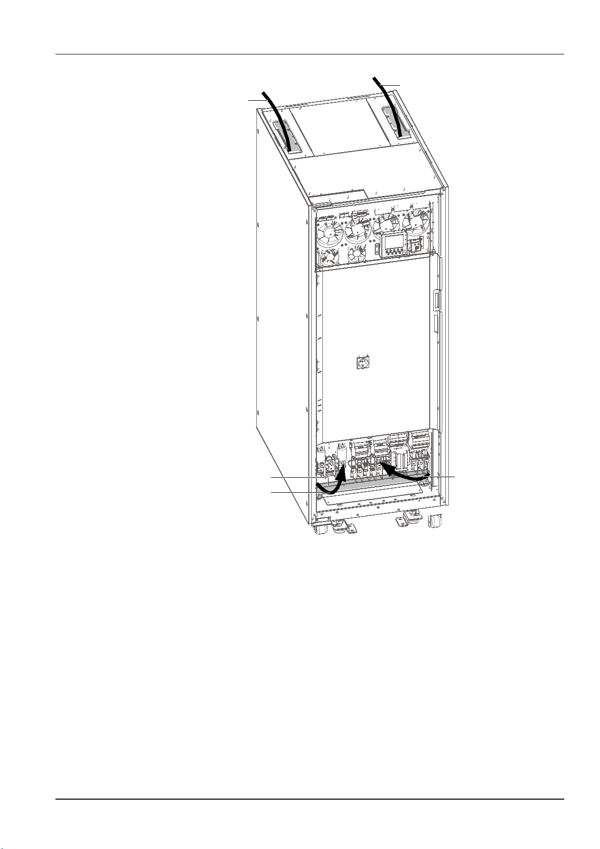
Note:
Step 1: Remove the left top cover, lead battery input cable and
PE input cable into the cabinet, and route them along left
side panel to cabinet base.
Step 2: Remove the cover panel of switch area, respectively connect cables
to battery input terminals and PE input terminal.
Step 3: Remover the right top cover, lead rectifer input cable, bypass input
cable and output cable into the cabinet and toute them along right
side panel to cabinet base.
Step 4: Respectively connect cables to the cabinet rectifier input termimals,
bypass input termimals and output termimals.
Cover panel of switch area
Step 2
Step 4
PE input cable into the cabinet, and route them along left
side panel to cabinet base
side panel to cabinet base.
Respectively connect cables to the cabinet rectifier input
terminals, bypass input terminals and output terminals.
Step 1
Step 3
Cover panel of switch area
Step 2
.
Chapter 3 Electrical Installation 25
Figure 3-3 Power cables wiring route (top cable access)
Liebert NXC 60kVA UPS User Manual
Page 41
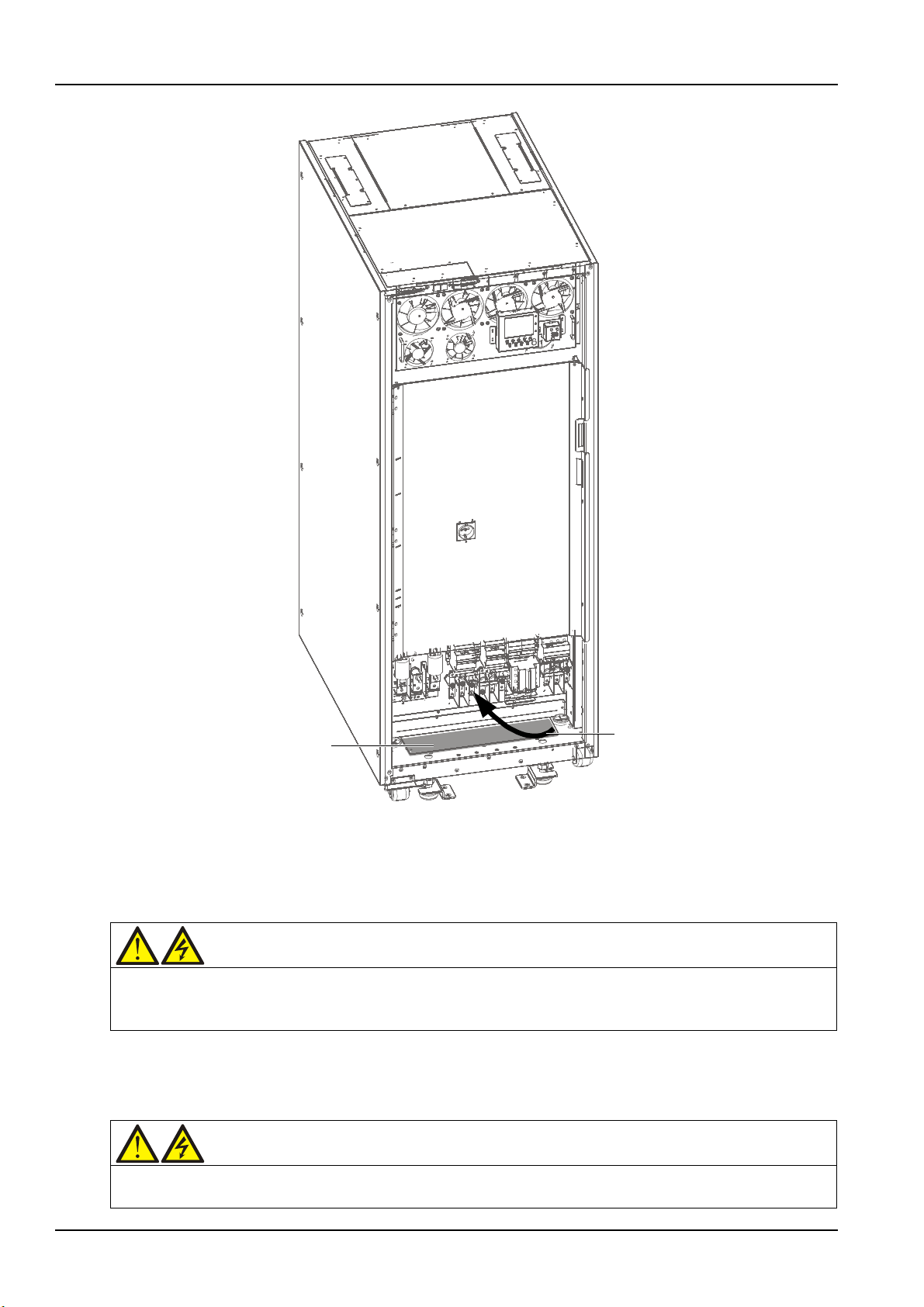
26 Chapter 3 Electrical Installation
Step
Bottom plate
Note:
Step: Remover the bottom plate, lead cables into the cabinet
and connect them to corresponding terminals.
Warning
Before cables connection, make sure that all external and internal power switches of the UPS are off, and post
Warning
1. The earth cables and neutral line must be connected in accordance with local and national codes of practice.
Bottom plate
Step
Step: Remover the bottom plate, lead cables into the cabinet
and connect them to corresponding terminals.
Figure 3-4 Power cables wiring route (bottom cable access)
necessary warning signs to prevent inadvertent operation of the switches. Meanwhile, measure the voltages
between the UPS terminals and the voltages between the terminals and the earth.
Refer to Figure 3-2 ~ Figure 3-4, open the front door of the UPS, and remove the protective cover (located
at the lower left corner) to reveal the power cable connection terminals (see Figure 3-2). Connect the
protective earth cable to the PE input terminal in the cabinet.
2. Failure to observe this could result in electric shock or fire risk.
Liebert NXC 60kVA UPS User Manual
Page 42
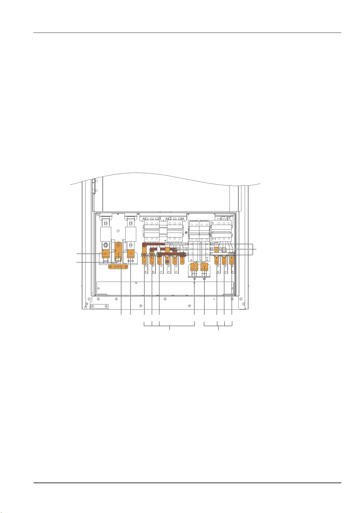
Chapter 3 Electrical Installation 27
Shorting copper bar of
common input configuration
+
N
PE
-
mA mB mC N oN oA oB oC
OutputMains input
Power distribution mode
According to the user's requirements, the I/O cable connections can be configured into two types:
3-in 3-out, common input configuration (factory default)
3-in 3-out, split bypass configuration
Connection of system input
1. 3-in 3-out, common input configuration (factory default)
Refer to Figure 3-5, connect the AC input cables to the bypass input terminals (bA-bB-bC) in the cabinet,
and ensure that the three shorting copper bars between the rectifier input terminals (mA-mB-mC) and
the bypass input terminals are connected correspondingly. Connect the input neutral line to the neutral
terminal N in the cabinet. Ensure correct phase rotation.
Note that the shorting copper bar of common input has been configured before delivery.
Figure 3-5 3-in 3-out, common input configuration cable connection (factory default)
2. 3-in 3-out, split bypass configuration
Refer to Figure 3-6, remove the three shorting copper bars between the rectifier input terminals
(mA-mB-mC) and the bypass input terminals (bA-bB-bC). Connect the rectifier input cables to the
rectifier input terminals (mA-mB-mC) in the cabinet, and connect the bypass input cables to the bypass
input terminals (bA-bB-bC) in the cabinet. Connect the rectifier input neutral line and bypass neutral line
to the neutral terminal N in the cabinet. Ensure correct phase rotation.
Liebert NXC 60kVA UPS User Manual
Page 43
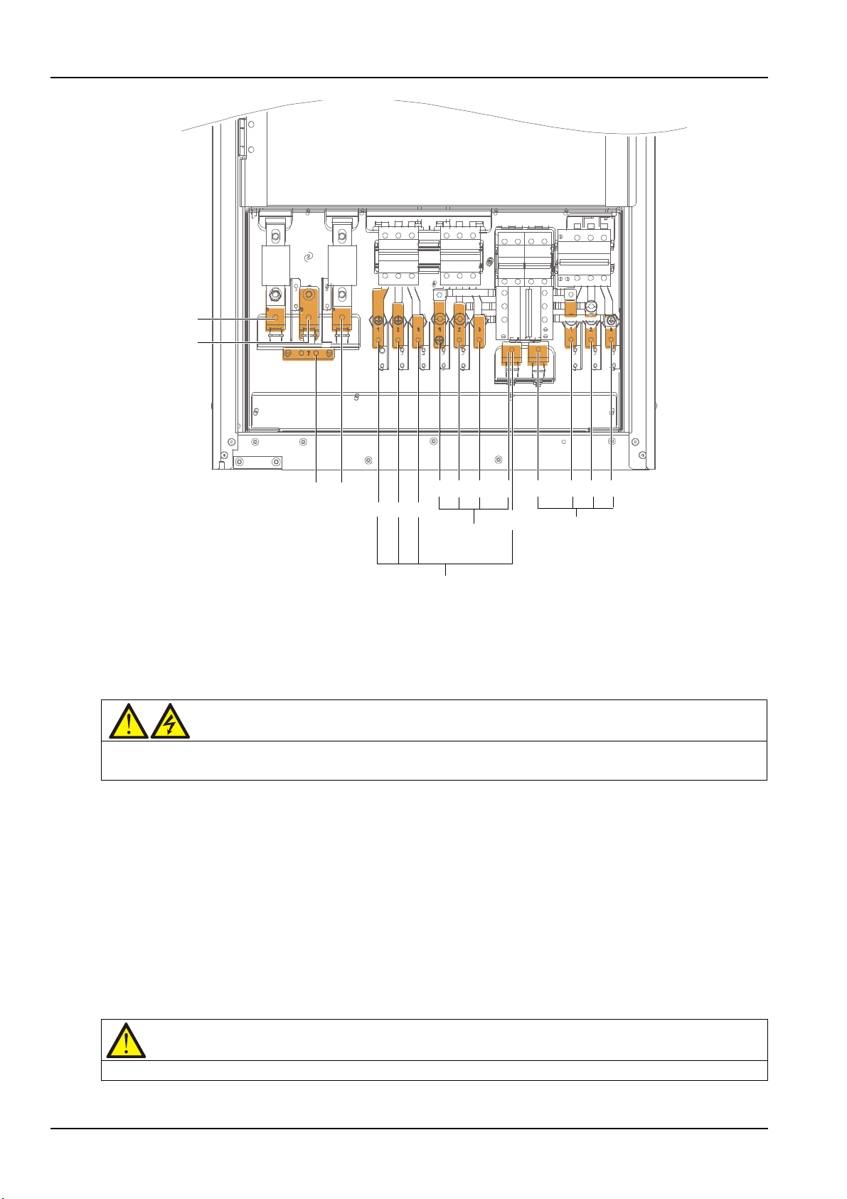
28 Chapter 3 Electrical Installation
+
N
PE
mA
mB
mC
bA bB bN
oN oA oB
oC
Output
bC
Bypass input
mN
Mains iput
Warning
If the load will not be ready to accept power supply before arrival of the service engineer, ensure that the system
Note
After connection, take appropriate measures to seal the cable entry holes.
Figure 3-6 3-in 3-out, split bypass configuration cable connection
Connection of system output
Connect the system output cables between the output terminals (oA-oB-oC-oN) in the cabinet and the
load. Refer to Table 3-1 for the torque. Ensure correct phase rotation.
output cables are safely isolated at their ends.
Connection of batteries
If the external battery is required, ensure correct polarity of the connections from the battery string
terminals to the BCB and from the BCB to the battery input terminals (BAT+, BAT N, BAT-) in the UPS
cabinet, that is, (BAT+) to (+) and (BAT-) to (-), (BAT N) to (N), but disconnect one or more battery cell
links in each tier. Do not reconnect these links and do not close the BCB before authorized to do so by the
service engineer.
Note: When connecting the cables between battery terminals and BCB, the connection should begin
from the BCB terminal.
Now the connection is finished. Then replace the protective covers.
Liebert NXC 60kVA UPS User Manual
Page 44
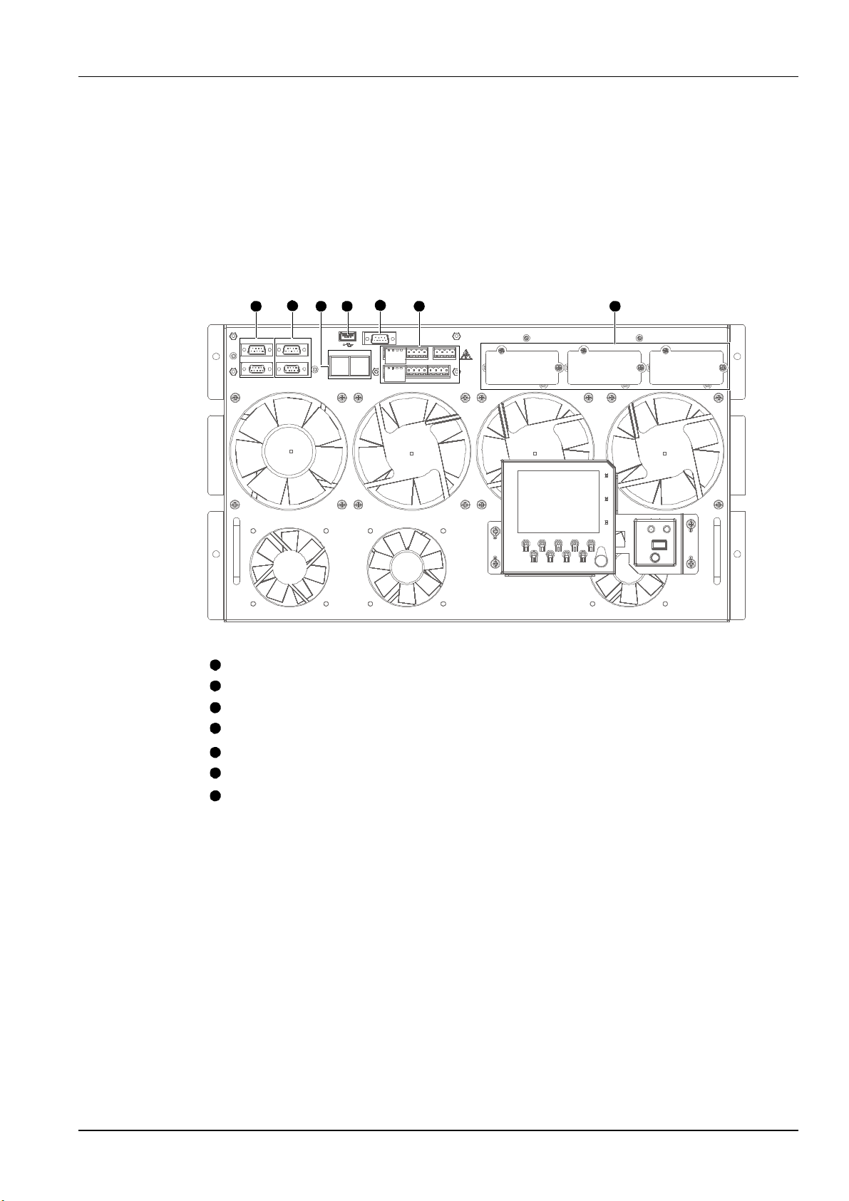
3.2 Wiring Of Signal Cable
LBS communication port
Parallel communication port
RS-485 communication port
USB communication port
RS232 communication port
User dry contact port
Intellislot port
Note:
1
2
3 4
5
6 7
1
1
1
2
3
4
5
6
7
3.2.1 Overview
For on-site specific needs, the UPS needs auxiliary connection to realize battery system (including the
external battery switch) management, communicate with PC, provide alarm signal to external devices,
realize remote EPO or provide bypass back feed circuit breaker signal and parallel communication. These
functions are realized through the communication box in the UPS cabinet. As shown in Figure 3-7, the
communication box provides the following ports:
Chapter 3 Electrical Installation 29
Figure 3-7 Illustration drawing of communication box ports
3.2.2 Input Dry Contact Port
The input dry contact ports J1 and J5 are shown in Figure 3-8 and described in Table 3-5. The input dry
contact voltage is 12Vdc, and the current is 20mA.
Liebert NXC 60kVA UPS User Manual
Page 45
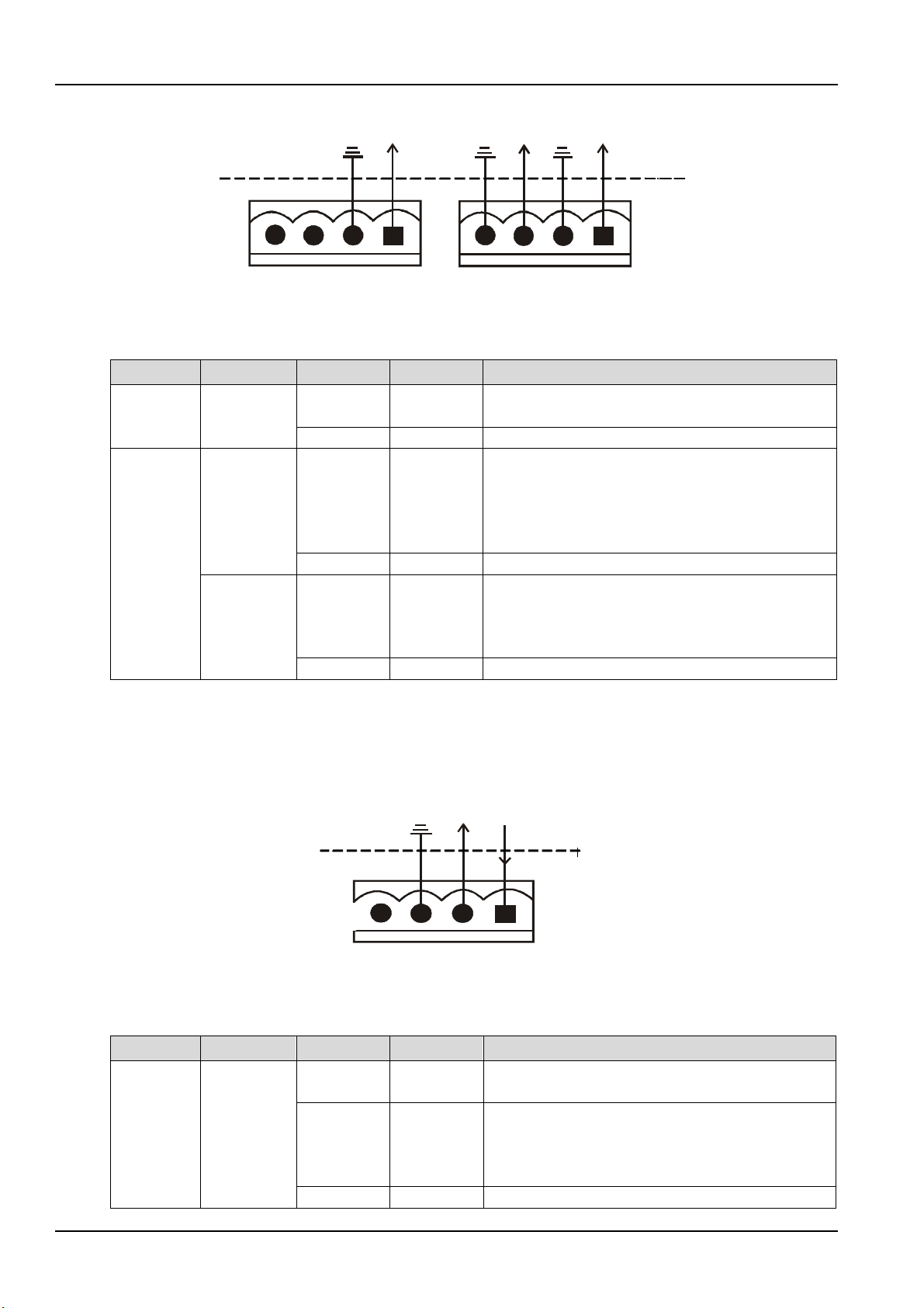
30 Chapter 3 Electrical Installation
GND
GND
GND
J1
J2
1
234
1
23
4
UPS
inside
External
ports
UPS inside
External port
J5
Silkscreen
Port
Pin No.
Pin name
Meanings
Generator is connected. Shorted to 1.1 and 1.2:
1.2
GND
GND
External maintenance bypass switch state. The
5.2
GND
GND
External output switch. The auxiliary contact
5.4
GND
5.3 and 5.4 have been shorted in factory
1234
J4
GND
UPS inside
External p orts
J2
Silkscreen
Port
Pin No.
Pin name
Meanings
BCB undervoltage release. Normally 12V, tripping at
BCB backfeeding signal input (normally open).
while auxiliary contact open upon circuit breaker open
2.3
GND
GND
Figure 3-8 Input dry contact ports J1 and J5
J1
J5
3.2.3 BCB Port
J2 is the BCB port. The port is shown in Figure 3-9 and described in Table 3-6.
Table 3-5
Generator
mode input
External
maintenanc
e bypass
switch
External
output
switch
Description of input dry contact ports J1 and J5
1.1 GEN
5.1 EXT_MAI
5.3 EXT_OUT
generator mode; opened to 1.1 and 1.2: normal mode
auxiliary contact requirement of the external
maintenance bypass switch: when 5.1 and 5.2 are
shorted, the external maintenance bypass switch is
closed
requirement of the external output switch: when 5.3
and 5.4 are shorted, the external output switch is
closed
J2 BCB
Figure 3-9 BCB port J2
Table 3-6 Description of BCB port J2
2.1 DRV
2.2 FB
0V
Normally open auxiliary contact signal of BCB:
Auxiliary contact closed upon circuit breaker closed,
Liebert NXC 60kVA UPS User Manual
Page 46
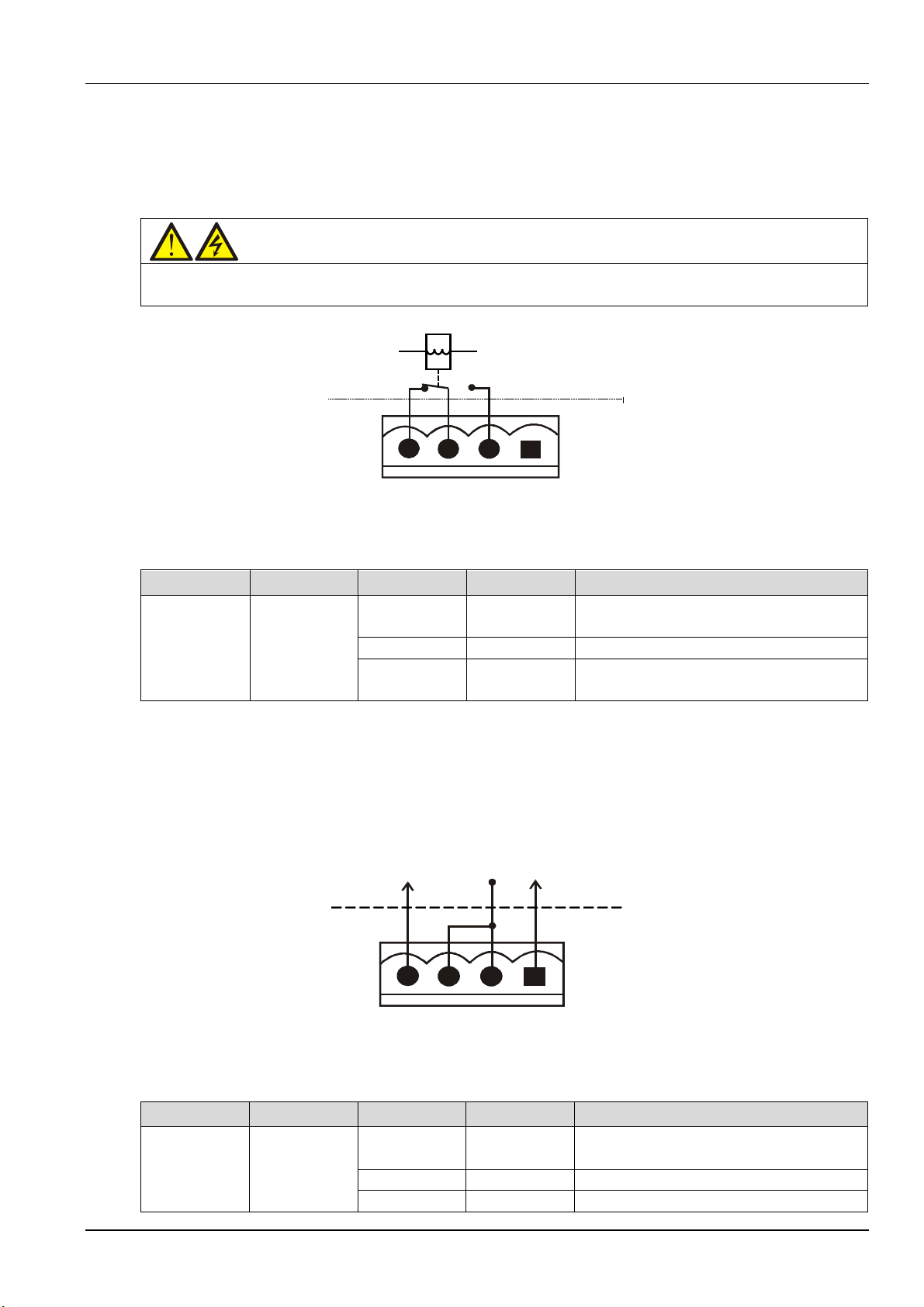
Warning
The voltage of the dry contact signal connected to J13 backfeed protection dry contact port may be dangerous.
J5
UPS内部
外部接口
1234
J5
UPS inside
External ports
1234
J5
UPS inside
Exter nal por ts
J3
Silkscreen
Port
Pin No.
Pin name
Meanings
Rectifier/bypass backfeed normally open
3.3
BFP_S
Rectifier/bypass backfeed common contact
Rectifier/bypass backfeed normally closed
+12V
1
23
4
J3
UPS inside
External ports
J4
Silkscreen
Port
Pin No.
Pin name
Meanings
EPO activated when opened to 4.2. Pins 4.1
4.2
+12V
EPO activated when opened to 4.1
4.3
+12V
EPO activated when shorted to 4.4
3.2.4 Backfeed Protection Dry Contact Port
The backfeed protection dry contact port J13 is shown in Figure 3-10 and described in Table 3-7. The
rated capacity of the backfeed protection dry contact is 240Vac/24Vdc, 5A.
Before connection, make sure that you are connecting the cable to the right port.
Figure 3-10 Backfeed protection dry contact port J3
Chapter 3 Electrical Installation 31
Table 3-7 Description of backfeed protection dry contact port J3
Rectifier/Bypa
J3
ss backfeed
output
3.2.5 Remote EPO Input Port
The UPS has an EPO function that operates by an EPO button on the operator control and display panel
of the UPS or by a remote contact provided by the user. The EPO switch has a protective cover.
J4 is the remote EPO input port. The port is shown in Figure 3-11 and described in Table 3-8.
3.2 BFP_O
3.4 BFP_C
contact. Open when there is no backfeed
contact. Closed when there is no backfeed
Figure 3-11 Remote EPO input port J4
Table 3-8 Description of remote EPO input port J4
J4
Remote EPO
input
Liebert NXC 60kVA UPS User Manual
4.1 EPO_NC
and 4.2 have been shorted in factory
Page 47
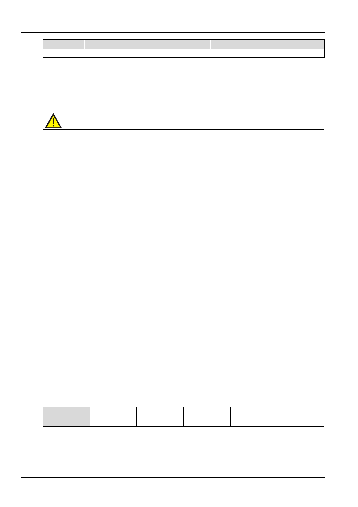
32 Chapter 3 Electrical Installation
Silkscreen
Port
Pin No.
Pin name
Meanings
4.4
EPO_NO
EPO activated when shorted to 4.3
Note
The UPS EPO action shuts down the rectifier, inverter and static bypass, but it does not internally disconnect the
Pin
1, 2
3, 6
4, 5 7 8
Definition
EPO is triggered when pins 3 and 4 of J4 are shorted or pins 2 and 1 of J4 are opened.
If an external EPO facility is required, pins 1 and 2 or 3 and 4 of J4 are reserved for this function. The
external EPO facility is also connected to the normally open or normally closed remote EPO switch
between these two terminals using shielded cable. If this function is not used, pins 3 and 4 of J4 must be
opened and pins 1 and 2 of J4 must be shorted.
mains input power. To disconnect all power to the UPS, open the external power switch, bypass input switch, output
switch and BCB after EPO is activated.
3.2.6 RS232 Communication Port
See Figure 3-7 for the position of RS232 port. RS232 port monitors and sets parameters through
connecting with computer.
The RS232 port provides serial data and is intended for use by authorized commissioning and service
personnel in UPS commissioning and service.
3.2.7 USB Communication Port
The position of the USB port is shown in Figure 3-7.
The USB port can connect the monitoring software.
The methods to connect the communication cable are as follows:
Insert one end of the USB communication cable to the USB port (see Figure 3-7) on the UPS, and connect
the other end to the USB port of the computer.
After the connection, you need to install the USB drive program in the installation disk.
Note: To make the communication normal, do not connect the RS232 port and USB port to the
computer at the same time.
3.2.8 Parallel And LBS Communication Ports
See Figure 3-7 for their positions.
3.2.9 RS485 Communication Port
See Figure 3-7 for its position. See Table 3-9 for definition of its pins, and see Figure 3-12 for the cable
connection diagram of RS485 communication port.
Table 3-9 Pins definition of RS485 communication port
NC NC GND D+ D-
Liebert NXC 60kVA UPS User Manual
Page 48
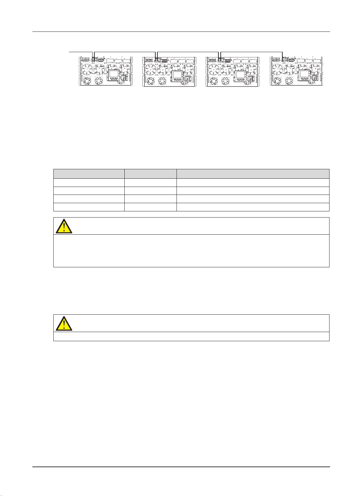
Connect to
monitoring host
3.2.10 Intellislot Port
Optional card
Model
Installation position
IS-UNITY-DP card
IS-UNITY-DP
Intellislot ports 1 ~ 3 (Intellislot port 2 recommended)
IS-Relay card
IS-Relay
Intellislot ports 1 and 3 (Intellislot port 1 recommended)
IS-485L card
IS-485L
Intellislot ports 1 and 3 (Intellislot port 3 recommended)
IS-WEBL card
IS-WEBL
Intellislot ports 1 ~ 3 (Intellislot port 2 recommended)
Note
1. The Intellislot port 2 shares communication resource with RS485 port. To avoid conflict, when using RS485 port in
Note
Respectively route the power cables and signal cables. The shielding coat of signal cable must be reliably earthed.
The Intellislot ports are used for installing optional cards on the site, including IS-UNITY-DP card, IS-Relay
card, IS-485L card, IS-WEBL card. Table 3-10 provides the models and installation positions of the optional
cards. For the detailed installation of the optional cards, refer to the corresponding contents in Chapter 8
Options.
Chapter 3 Electrical Installation 33
Figure 3-12 Cable connection diagram of RS485 communication port
Table 3-10 Models and installation positions of optional cards
service and commissioning, it is not recommended to use the Intellislot port 2.
2. The Intellislot port 3 shares communication resource with RS232 and USB ports. To avoid conflict, when using
RS232 and USB ports in service and commissioning, it is not recommended to use the Intellislot port 3.
3.2.11 Signal Cable Connection Steps
Two connection modes are available: top cable access, bottom cable access. See Figure 3-13 and Figure
3-14.
Liebert NXC 60kVA UPS User Manual
Page 49
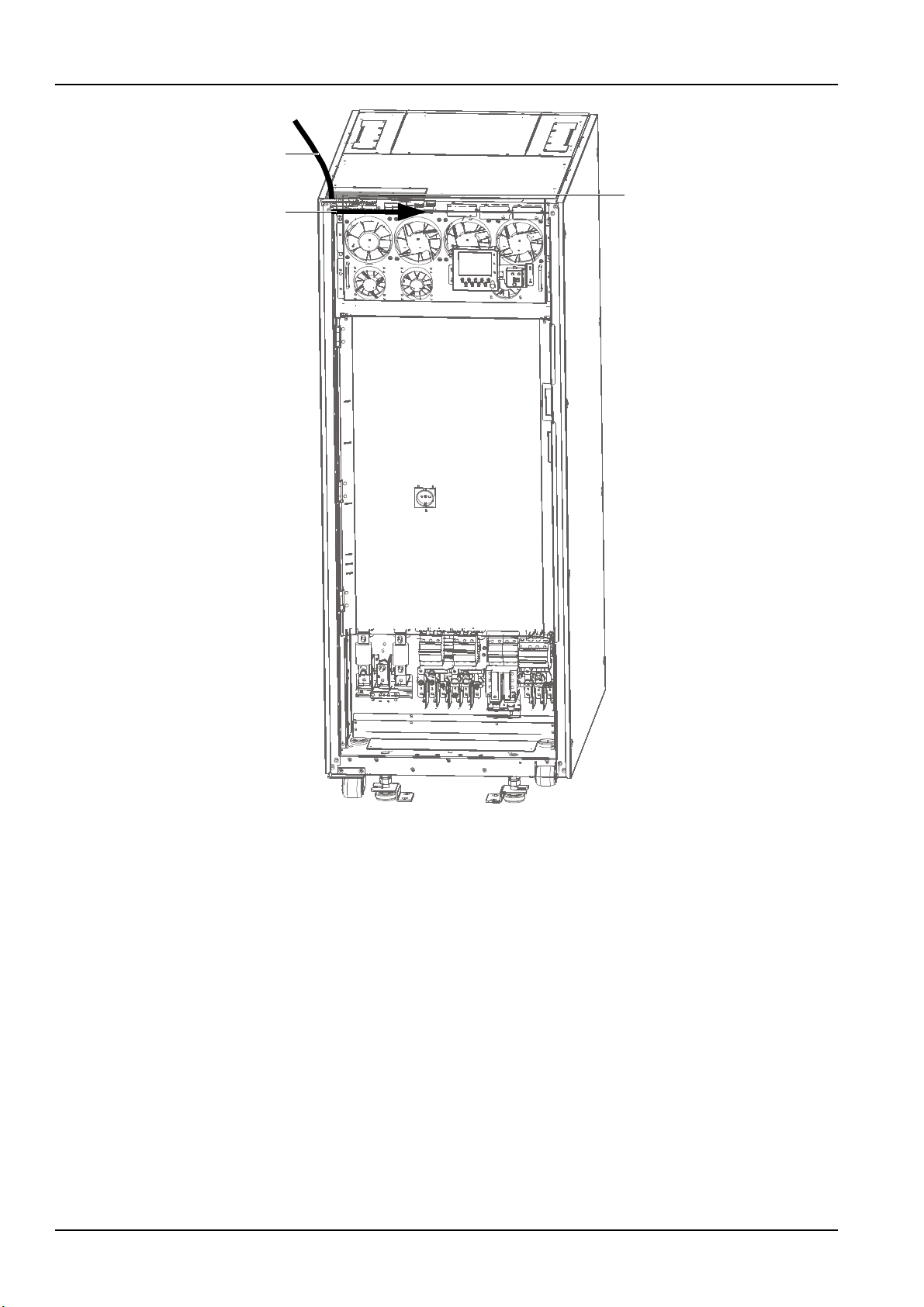
34 Chapter 3 Electrical Installation
Step 1
Step 2
Top cover
Note:
Step 1: Remove the top cover, lead cables into the cabinet
Step 2: Connect cables to corresponding terminals.
Figure 3-13 Signal cables wiring route (top cable access)
Liebert NXC 60kVA UPS User Manual
Page 50
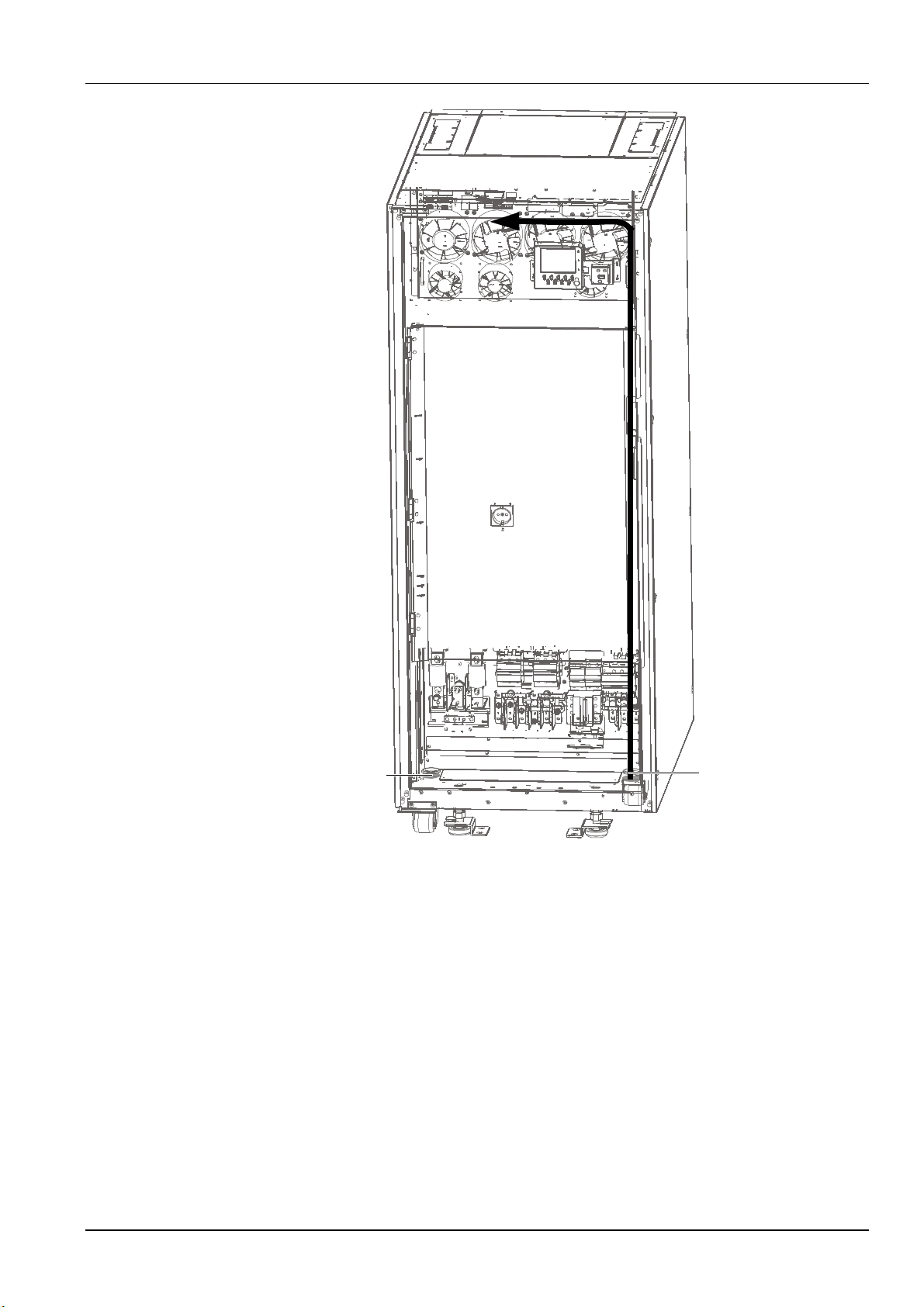
Chapter 3 Electrical Installation 35
Note:
Step: Take priority selection of the right side
cable inlet, lead cables into the cabinet and
route them along the cabinet inside, then
connect them to corresponding termimals.
Step
Cable inlet (one for left
and one for right)
connect them to corresponding terminals.
Cable inlet (one for left
and one for right)
Figure 3-14 Signal cables wiring route (bottom cable access)
Liebert NXC 60kVA UPS User Manual
Page 51
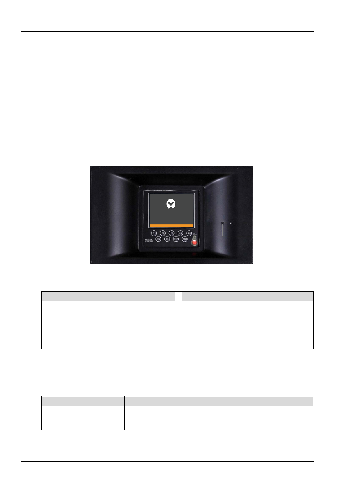
36 Chapter 4 Operator Control And Display Panel
VERTIV
TM
2
1
No.
Function
Key
Function
F1 ~ F5
LCD menu keys
FAULT CLEAR
Fault reset switch
ON
Inverter start switch
OFF
Inverter shutdown switch
ALARM CLEAR
Alarm silencing switch
EPO
EPO switch
Indicator
Status
Description
Solid green
Load powered by the inverter
Flashing green
Inverter turning on, starting up, synchronizing or in stand-by state (ECO mode)
Off
Inverter off
Chapter 4 Operator Control And Display Panel
This chapter expounds the functions and use of the components on the operator control and display
panel of the UPS, provides LCD display information, including the LCD screen types, detailed menu
messages, prompt windows and UPS alarm list.
4.1 Introduction
The UPS front provides the operator control and display panel. It is the access point for operator control
and query all measured parameters, UPS and battery status and alarms.
The operator control and display panel is divided into three functional areas: LCD screen, LED indicator
and control keys, as shown in Figure 4-1, and as described in Table 4-1.
1 Inverter indicator (Green)
2 Alarm indicator (Red)
4.1.1 LED Indicators
The two indicators show the current working state of the UPS, see Table 4-2 for details.
Inverter
indicator
Figure 4-1 Operator control and display panel
Table 4-1 Description of components of the operator control and display panel
Table 4-2 Definition of indicators
Liebert NXC 60kVA UPS User Manual
Page 52
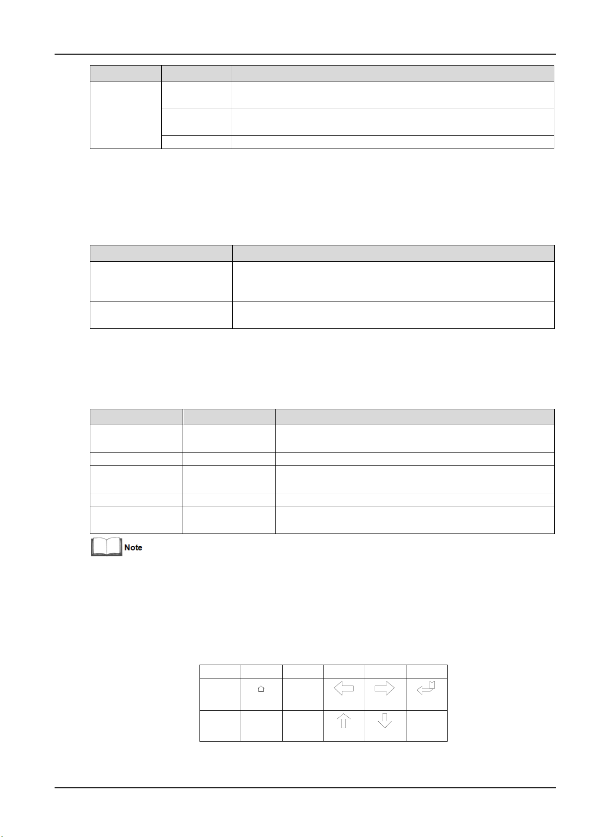
Chapter 4 Operator Control And Display Panel 37
Indicator
Status
Description
Rectifier not ready or critical fault (fro example, inverter relay short circuit,
General fault (for example, module overload, battery disconnected, fan failure
Off
No fault
Alarm sound
Meaning
Alarm upon a general fault, for example, module overload, battery
Alarm upon a general fault, for example, inverter relay short circuit, bypass STS
Control key
Silkscreen
Description
Cut off the load power and battery, shut down the rectifier, inverter,
Inverter start switch
ON
Start the inverter
Inverter shutdown
Fault reset switch
FAULT CLEAR
Clear fault to restart the UPS
Alarm silencing
When an alarm is active, pressing this key silences the audible
Function
1
Function
2
F1 F2 F3 F4
ESC
Escape Left
Up
Right
Down
Enter
Key
F5
HOME
Solid red
Alarm indicator
Flashing red
4.1.2 Audible Alarm (Buzzer)
UPS activity is accompanied by the two kinds of sound listed in Table 4-3.
Beep every other second
Continuous beep
4.1.3 Control Keys
The operator control and display panel provides five control keys, as described in Table 4-4.
bypass STS short circuit, bypass backfeed and inverter fault, etc.)
and parallel load sharing failure, etc.)
Table 4-3 Description of audible alarm
disconnected, fan failure, parallel load sharing failure and battery discharge
pre-alarm, etc.
short circuit, bypass backfeed and inverter fault, etc.
EPO switch EPO
switch
switch
It is required to hold and press the preceding keys for 2s to initiate the key function.
4.1.4 LCD And Menu Keys
The operator control and display panel provides an LCD screen and five menu keys (F1 ~ F5). The menu
keys are described in Table 4-5.
Table 4-4 Description of control keys
static bypass
OFF Shut down the inverter
ALARM CLEAR
Table 4-5 Description of menu keys
alarm. Pressing this key again enables the buzzer again
Providing 320 × 240 dot matrix graphic display, the user-friendly and menu-driven LCD allows you to
easily browse through the input, output, load and battery parameters of the UPS, get current UPS status
Liebert NXC 60kVA UPS User Manual
Page 53
38 Chapter 4 Operator Control And Display Panel
Liebert
R
and alarm information, and perform functional setting and control operation. The LCD also stores up to
2048 historical records that can retrieve for reference and diagnosis.
4.2 LCD Screen Type
4.2.1 Start Screen
Upon UPS start, the UPS executes self-test, and the start screen appears and remains approximately 25
seconds, as shown in Figure 4-2.
4.2.2 Primary Screen
After the UPS starts and finishes self-test, the primary screen appears, as shown in Figure 4-3. The
primary screen is divided into four windows: system information window, data window, menu window and
keypad window.
Figure 4-2 Start screen
Liebert NXC 60kVA UPS User Manual
Page 54
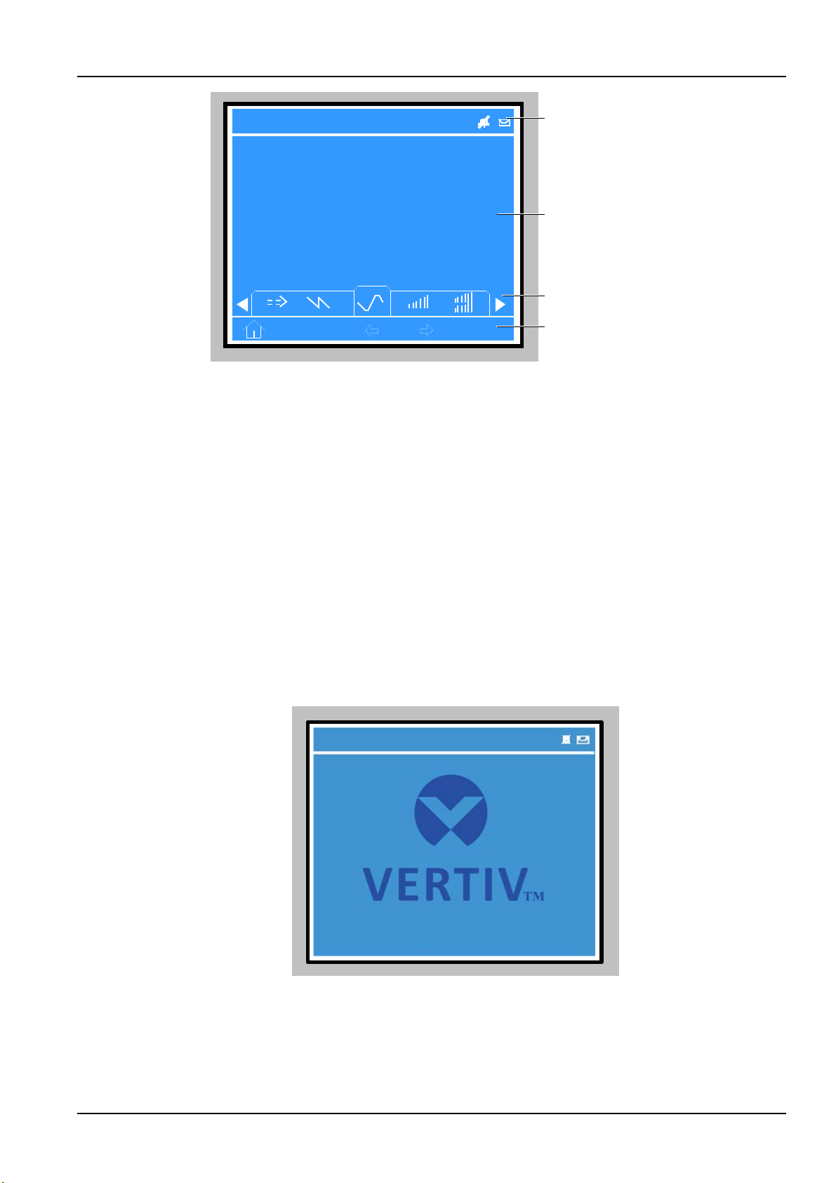
Chapter 4 Operator Control And Display Panel 39
#1
NXC 60kVA
OutPut
220 220 220
20.5 20.5 20.5
50.1 50.1 50.1
380 380 380
0.99 0.99 0.99
System information window
Data window
Menu window
Keypad window
16:21:17
A(AB) B (BC)
C
(CA)
L-N voltage (V)
Frequency (HZ)
L-N current (V)
L-L voltage (V)
Power factor
16
:21:17
#1
APM 600kVA
Liebert
R
16:21:17
NXC 60kVA
#1
Figure 4-3 Primary screen
The functions of the menu keys F1 ~ F5 are shown by self-explanatory icons in the keypad window as
appropriate. From any menu on the primary screen, pressing the F1 key returns to the 'OutPut' menu.
4.2.3 Default Screen
During UPS operation, if there is no alarm or key action within two minutes, the default screen will appear,
as shown in Figure 4-4. After a short delay, the LCD backlight will turn off. Pressing any menu keys (F1 ~
F5) restores the default screen.
4.3 Detailed Description Of Menu Items
The description that follows refers to the LCD primary screen shown in Figure 4-3.
Figure 4-4 Default screen
Liebert NXC 60kVA UPS User Manual
Page 55
40 Chapter 4 Operator Control And Display Panel
Item
Explanation
NXC
UPS series name
Single: UPS module system with dual conversion
60kVA
UPS power is 60kVA
16:21:17
Current time (format: 24 hours, hour: minute: second)
/
Audible alarm enabled or disabled. : disabled, : enabled
System information window
The system information window displays the current time, UPS name, configuration and alarm silencing
state. This window requires no user operation. For details, see Table 4-6.
Table 4-6 Item description of system information window
(Configuration)
Single/ECO/Unit1#
ECO: The UPS is set as a UPS module system, and runs in ECO mode
Unit1#: #1 of the parallel system formed by up to four UPS modules
Menu window and data window
The menu window provides the menus of the data window. The data window displays the items of the
menu selected in the menu window. UPS parameters can be browsed and functions can be set through
the menu window and data window. Details are provided in Table 4-7.
Liebert NXC 60kVA UPS User Manual
Page 56

Menu
Item
Explanation
Mains
L-N voltage (V)
Phase voltage
L-N current (A)
Phase current
Frequency (Hz)
Input frequency
L-L voltage (V)
Line voltage
Power factor
Power factor
L-N voltage (V)
Phase voltage
Frequency (Hz)
Bypass frequency
L-L voltage (V)
Line voltage
L-N voltage (V)
Phase voltage
L-N current (A)
Phase current
Frequency (Hz)
Output frequency
L-L voltage (V)
Line voltage
Power factor
Power factor
S
(kVA)
S
: apparent power
P
(kW)
P
: active power
Q
(kVAR)
Q
: reactive power
Load level (%)
Load (expressed in percentage of the UPS rating load )
Crest factor
Output current crest factor
S
(kVA)
S
: apparent power
P
(kW)
P
: active power
Q
(kVAR)
Q
: reactive power
Single unit, no
Displayed on this data window when the UPS is configured as a single
Battery voltage (V)
Battery bus voltage
Battery current (A)
Battery bus current
Battery temperature
Battery remain time
Battery capacity (%)
Percentage of battery life when compared to a new battery
Battery boost
Battery float
Battery is not
Event
(active alarm)
Display the active alarms
Records
(alarm history)
Display the alarm history
Language
(language option)
Provide 17 optional LCD languages
Bypass
OutPut
Chapter 4 Operator Control And Display Panel 41
Table 4-7 Item description of menu window and data window
Load
System
Battery
out
out
out
out
out
out
parallel system data
(°C)
(Min.)
charging
charging
out
out
out
out
out
out
unit
Built-in battery temperature
Remaining battery backup time
Battery is boost charging
Battery is float charging
connected
Battery is not connected
Liebert NXC 60kVA UPS User Manual
Page 57

42 Chapter 4 Operator Control And Display Panel
Menu
Item
Explanation
Display contrast
Adjust the LCD contrast
Date format set
Three formats selectable: MM/DD/YYYY, DD/MM/YYYY, YYYY/MM/DD
Date & time
Set the date and time
Comm1 baud rate
Set the communication baud rate of the Intellislot port 1
Comm2 baud rate
Set the communication baud rate of the Intellislot port 2
Comm3 baud rate
Set the communication baud rate of the Intellislot port 3
Communication
Single Group Batt
Battery Cells
Equalize Charge
Temp Compensation
Enabled, Disabled
Shared Battery
Enabled, Disabled
System
Parallel Requisite
Parallel Redundant
Provide one ID code for single module in parallel system, when 'Parallel' is
ECO Mode
Normal, ECO
Output Frequency
Output Voltage
LBS Function
NONE, SLAVE, MASTER
Command password
The user can modify the command password
Protocol
Velocity
Battery maintenance
20% battery capacity is out upon battery maintenance test. Load must
Perform a full discharge of the battery to obtain a precise measure of the
Self-test of the UPS. When the user activates this function, a window
Manually stop a battery maintenance test, battery capacity test or
Freshening charge
Manually initiate a battery freshening charge
Stop freshening
Eff.Curve
Eff.Curve
Display the system efficiency at current load
UPS Run time
Display UPS accumulated run time
Byp. Run time
Display UPS accumulated run time on bypass
UPS version
Provide UPS inverter, rectifier and monitoring software versions
UPS model
Provide UPS model information, for example, 208V-60Hz
Settings
address
Cap
Number
Allowed
Configuration
units
units
Parallel ID
Level
Level
Applicable to RS485 communication
Set the capacity of battery unit
Set the battery cells connected to the UPS
Battery boost charge is enabled or not
Single, Parallel
Basic number of single modules in parallel system
Redundant number of single modules in parallel system
set
Set the system output frequency (unit: Hz); 50/60
The voltage between phase line and phase line
Command
(initiate, stop
battery, system
test or
freshening
charge
test
Battery capacity test
System test
Stop testing
charge
be between 20% and 80%
battery capacity. Load must be between 20% and 80%
appears about 5s later to show the test result
system test
Manually stop a battery freshening charge
Run Time
Version
Liebert NXC 60kVA UPS User Manual
Page 58

Keypad window
Prompt
Meaning
Transfer with interrupt, confirm or
The total load must be less than the capacity of one UPS to allow a
This operation leads to output
The bypass is abnormal, turning off the inverter will cause the load to be
This operation leads to inverter
Turning off this inverter will lead to the overload of the remaining
The number of inverters already turned on is insufficient to carry the
If you select battery maintenance test, the battery will discharge until
System self test finished, everything is
Please check the current warnings
Check the active alarm messages
Enter control password
Required for battery or UPS test (default: 12345)
Battery Self Test aborted, conditions not
Battery self-test condition is not met. Please check if the battery is in
This prompt appears when you select the Freshening charge command
Alarm
Explanation
Fault reset
FAULT CLEAR key on the operator control and display panel pressed
Rectifier in setting
The rectifier starts up and is in synchronization
Inverter in setting
The inverter starts up and is in synchronization
Manual turn on
ON key on the operator control and display panel pressed to turn on the inverter
Manual turn off
OFF key on the operator control and display panel pressed to turn off the inverter
The inverter failed to turn on when the ON key is pressed. This may be the result of an
Soft start fail
Owing to low DC bus voltage, the rectifier will report this alarm
The functions of the menu keys (F1 ~ F5) for the current screen are shown by self-explanatory icons in the
keypad window as appropriate.
4.4 Prompt Window
A prompt window is displayed during the operation of the system to alert you to certain conditions or to
require your confirmation of a command. The prompts are provided in Table 4-8.
Chapter 4 Operator Control And Display Panel 43
Table 4-8 Prompts and meanings
cancel
The load is too high to be transferred
with interrupt
shutdown, confirm or cancel
overload, confirm or cancel
Turn on more UPS to carry current load
Battery will be depleted, confirm or
cancel
OK
met
Battery Refresh Charge aborted,
conditions not met
The load executes interval transfer between the inverter and bypass
parallel system to perform an interrupted transfer from bypass to
inverter
disenergized
inverter(s) in a parallel system
existing load. The user is required to turn on more UPSs
the UPS shuts down. This prompt appears to require your confirmation.
Canceling the test will ends the test and transfers the UPS to inverter
mode
No action required
boost charge state and the load is more than 20%
while the a battery freshening charge condition (such as no battery,
charger failure
) is not met
4.5 Alarm List
Table 4-9 provides the complete list of UPS alarm messages for display either on the 'Event' menu or on
the 'Records' menu described in Table 4-7.
Table 4-9 UPS alarm list
Turn on fail
invalid operation (maintenance bypass switch closed) or DC bus or rectifier not ready
Liebert NXC 60kVA UPS User Manual
Page 59

44 Chapter 4 Operator Control And Display Panel
Alarm
Explanation
Alarm silence
ALARM CLEAR key on the operator control and display panel pressed
ALARM CLEAR key on the operator control and display panel pressed in alarm silence
Bypass mode
The UPS is in bypass mode
Normal mode
The UPS is in normal mode
Battery mode
The UPS is in battery mode
UPS shutdown
UPS shutdown with no output power
Output disabled
EOD event happened. Check the battery voltage
System Bypass STS
Mains volt. abnormal
The mains voltage is outside specifications and results in rectifier shutdown
At least one phase main input voltage is within 132V ~ 176V, thus the load should be
Mains freq. abnormal
The mains frequency is outside specifications and results in rectifier shutdown
Mains phase reversed
The AC input phase rotation is reversed
Input feedback
Battery voltage fed back to rectifier input
Mains neutral lost
AC rectifier input neutral line not detected
Input current
Input curr. over limit
Input current over limit
Bypass unable to
The bypass frequency is outside specifications. This alarm automatically resets once the
The amplitude or frequency of the bypass voltage exceeds the limit. This alarm
At least one of the STSs at the bypass side is open or shorted. This fault is locked until
Byp. abnormal
Bypass phase
Bypass overcurrent
The bypass current is outside the rated current
Rectifier fault
Bus voltage abnormal or battery SCR short circuit
Rectifier overtemp.
The alarm occurs due to rectifier overtemperature
The rectifier, inverter and battery converter shut down because the DC bus voltage is too
The DC bus voltage is abnormal and results in inverter shutdown. The load transfers to
Inverter
The output voltage and bypass voltage are misaligned in phase. This alarm resets
Inverter fault
Inverter output voltage outside specifications. Load transfers to bypass
At least one of the inverter relays is opened or shorted. This fault is locked until mains
Output fuse fail
At least one of the inverter output fuses is blown
Output volt. abnormal
At least one phase of the output voltages is abnormal
This alarm appears when the load rises above 105% of the nominal rating. The alarm
This alarm appears when the total load rises above 105% of the nominal rating of the
The UPS overload status continues and the overload times out.
Load impact transfer
A transfer to bypass occurred due to a large step load. The UPS can recover automatically.
Audible alarm reset
fail
Mains undervoltage
abnormal
trace
Bypass abnormal
state
The adjacentbypass STS open circuit fault or short-circuit fault
derated
Battery load sharing imbalance or rectifier input current abnormal
bypass voltage goes normal
automatically resets once the bypass voltage returns to normal.
Bypass STS fail
shutdown
reversed
DC bus over voltage
DC bus abnormal
asynchronous
Inverter relay fail
Unit overload
power-off
Both the bypass and inverter voltages are abnormal, and the output is off
The phase rotation of the bypass voltage is reversed
high. The load transfers to bypass
bypass
automatically once the condition is no longer true
power-off
automatically resets once the overload condition is removed
System overload
Unit overload timeout
parallel system. The alarm automatically resets once the overload condition is removed
When the time has expired, the load automatically transfers to the bypass
Liebert NXC 60kVA UPS User Manual
Page 60

Chapter 4 Operator Control And Display Panel 45
Alarm
Explanation
Turn on the load equipment in stages to reduce the load impact on the inverter
The load remains on bypass power owing to excessive number of transfers that occurred
Load sharing
All UPSs in the parallel system transfer to bypass at the same time when one of them
Control power fail
The auxiliary power failure or power-off
EPO button on operator control and display panel pressed or external EPO command
Fan abnormal
At least one fan has fault
Maintenance bypass switch is closed when the parallel system is on inverter, or output
LBS active
The LBS setting is active
LBS abnormal
LBS is abnormal
Maint. sw. open
Maintenance bypass switch is open
Maint. sw. closed
Maintenance bypass switch is closed
Output sw. closed
Output switch is closed
Output sw. open
Output switch is open
Charger fault
Battery charger has failure
Dischg. curr. limit
Discharge current is over limit, close the discharger
Auto start
After UPS shutdown at EOD, the inverter automatically starts upon mains restoration
Freshening boost
Rec flash update
Rectifier software being updated
Inv flash update
Inverter software being updated
Monitor flash update
Monitoring software being updated
FLASH operate fail
Historical record not saved
Remote turn ON
Turn on the inverter through the service command
Remote turn ON
Caused by invalid operation (maintenance bypass switch closed), DC bus or rectifier not
Remote turn OFF
Turn off the inverter through the service command
Load sharing
Communication fail
Interruption in communication between internal monitoring board and inverter, rectifier
Communication between the UPS modules of a parallel system failed. Check if any UPS
No battery
Check the battery and battery connection
Batt. converter fault
Bus voltage abnormal
Battery reverse
Reconnect battery and check battery wiring
The battery is under automatic periodic battery maintenance test (20% capacity
Batt. capacity testing
The user initiated a battery capacity test (100% capacity discharge)
Battery maintenance
Battery end of
Battery overtemp.
The battery temperature is over limit
Battery low
Before the EOD, battery low pre-warning will occur. After this pre-warning, the battery will
Transfer time-out
abnormal
System transfer
EPO
Operation invalid
within one hour
The UPSs in a parallel system are not sharing the load current correctly
needs to transfer to bypass. This message appears on the LCD of the UPS with passive
transfer to bypass
received
switch and maintenance bypass switch are closed when the inverter is on
charge
failed
abnormal
Parallel comm. fail
Battery period testing
The battery is forced to be in boost charge state
ready
Each UPS module is parallel system cannot execute load sharing
modules in the parallel system are not on; if yes, power on these UPSs and then check if
the alarm disappears
discharge)
testing
discharge
The user initiated a maintenance test (20% capacity discharge)
Inverter turned off due to battery EOD
Liebert NXC 60kVA UPS User Manual
Page 61
46 Chapter 4 Operator Control And Display Panel
Alarm
Explanation
pre-warning
have the capacity for 3min discharging with full load. The time is user-settable from 3min
Generator in
Dry contact signal, indicating generator connected
BCB status abnormal
Logic conflict between BCB drive signal and feedback signal
BCB closed
BCB state (closed)
BCB open
BCB state (open)
Bypass overtemp.
The temperature at bypass side exceeds the threshold
The current at bypass side exceeds the thresholdm and protection time, then the system
Boost Charge
The boost charge alarm occurs when battery boost chagre time exceeds the set range (12
If the transformer has over-temperature signal, the inverter shuts down and the bypass
System Fan
Alarm: 'System fan1 abnormal' or ' System fan2 abnormal'. For front view of the UPS, left is
to 6min
Byp. overcurr. timeout
Timeout
Output TX Overtemp
Abnormal
1. For UPS installed with the optional battery monitor, refer to the user manual of the battery monitor for the alarm
messages related to battery cell and charge current.
2. If the alarm is caused through setting the software value by Vertiv authorized engineer, and you wish to change the
setting values, please contact the Vertiv local customer service center.
disconnects the bypass output
hours by default), then the system transfers to float charge
switch is invalid, then the UPS powers off
fan1 while right is fan2
Liebert NXC 60kVA UPS User Manual
Page 62
Chapter 5 UPS Operation Introduction
Important
The user can conduct relative operation only after the authorized engineer carries out the first power on and test.
Warning: hazardous mains and/or battery voltage
1. No operator-serviceable parts are located behind covers that require a tool for their removal. Only qualified service
This chapter introduces the operating precautions and operating methods of UPS in detail.
5.1 Brief Introduction
5.1.1 Precautions
personnel are authorized to remove such covers.
2. The AC input and output terminals of UPS have dangerous voltage at any time. If the cabinet is equipped with an
EMC filter, the filter may have dangerous voltage.
1. For the control keys and LCD related to all the operating steps, refer to Chapter 4 Operator Control
And Display Panel.
Chapter 5 UPS Operation Introduction 47
2. During operation, the buzzer alarm may occur at any time. Press ALARM CLEAR key to silence the
audible alarm.
3. When UPS uses traditional lead-acid battery, the system provides boost charge optional function. If the
lead-acid battery is used, when the mains returns after an extended mains failure, the charging voltage of
the battery will be higher than the normal charging voltage, this is normal, and the charging voltage of the
battery will return to normal value after a few hours' charging.
5.1.2 Power Switch
Opening the front door of the UPS cabinet reveals the power switches, as shown in Figure 5-1, including:
Q1: Rectifier input switch, which connects UPS to the main circuit power.
Q2: Bypass input switch, which connects UPS to the bypass.
Q3: Maintenance bypass switch (lockable), which supplies power to the load when UPS is being
maintained.
Note: If the UPS system is composed of more than 2 paralleled UPS modules, do not use the internal
maintenance bypass switch.
Q5: Output switch, which connects UPS output to the load.
Q6: Neutral line switch (lockable).
Liebert NXC 60kVA UPS User Manual
Page 63
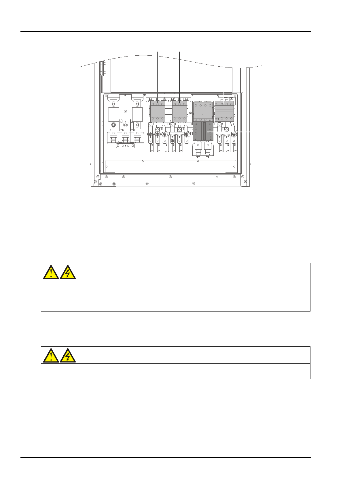
48 Chapter 5 UPS Operation Introduction
Q1 Q2
Q6
Q5
Q3
Warning
1. These procedures result in mains voltage being applied to the UPS output terminals.
If the load is not ready to receive power, please disconnect the downstream load switch, and stick a warning label on
Warning
To avoid misreporting as faults, all operations relating to disconnection or connection of the maintenance bypass
Figure 5-1 UPS power switch
5.2 UPS Startup Procedures
The UPS must be completely installed and tested by authorized engineer, and external power supply
switch is closed, then you can start the UPS.
5.2.1 Startup Procedures In Normal Mode
2. If any load equipment is connected to the UPS output terminals, check with the user that it is safe to apply power.
the connection point of the load.
Use the following procedures to turn on the UPS from a fully powered down condition.
1. Open the front door of the UPS, ensure that the internal maintenance bypass switch Q3 is disconnected
and switch Q6 is closed, while the input cables and copper bars are reliably connected.
switch shall be finished within three seconds.
2. Close the bypass input switch Q2, rectifier input switch Q1, output switch Q5 and all external output
isolating switches (if any) of the UPS in turn.
At the moment, the system is powered on, and the startup screen pops up. Refer to 4.2.1 Start Screen.
About 25 seconds later, confirm that the LCD shows the rectifier power supply and the bypass power
supply are normal; if not, check whether the switches Q1 and Q2 are closed. Then the rectifier starts up
and the alarm indicator (red) is on. At the same time, the bypass static switch is closed. About 30 seconds
later, the alarm indicator (red) is flashing, and then the rectifier startup is finished.
Liebert NXC 60kVA UPS User Manual
Page 64
3. Press the ON key for two seconds.
Warning
To avoid misreporting as faults, all operations relating to disconnection or connection of the maintenance bypass
UPS operated in ECO mode
The inverter starts up, and the inverter indicator (green) is flashing. After the inverter runs normally, the
UPS transfers from the bypass to inverter, then the inverter indicator (green) is on.
5.2.2 Startup Procedures In ECO Mode
1. If ECO mode is required, contact Vertiv service engineer to set it through the setting software. If you
wish to set it by yourself, you can enable it through the sub-menu under 'Settings' on the LCD screen.
2. Open the front door of the UPS, ensure that the internal maintenance bypass switch Q3 is disconnected
and switch Q6 is closed, while the input cables and copper bars are reliably connected.
switch shall be finished within three seconds.
3. Close the bypass input switch Q2, rectifier input switch Q1, output switch Q5 and all external output
isolating switches (if any) of the UPS in turn.
At the moment, the system is powered on, and the startup screen pops up. Refer to 4.2.1 Start Screen.
About 25 seconds later, confirm that the LCD shows the rectifier power supply and the bypass power
supply are normal; if not, check whether the switches Q1 and Q2 are closed. Then the rectifier starts up
and the alarm indicator (red) is on. At the same time, the bypass static switch is closed. About 30 seconds
later, the alarm indicator (red) is flashing, then the rectifier startup is finished.
Chapter 5 UPS Operation Introduction 49
4. Press the ON key for two seconds.
The inverter starts up, and the inverter indicator (green) is flashing. At this time, the UPS is in ECO mode,
and powered by the bypass.
5.2.3 Startup Procedures In Battery Mode (Battery Cold Start)
1. Verify that the battery has been connected, and that the battery voltage is transferred to the input
terminal of the battery.
2. Open the front door, and press the battery cold start button (see Figure 5-2 for its position).
At the moment, the startup screen pops up. Refer to 4.2.1 Start Screen.
About 25 seconds later, the rectifier starts up and the alarm indicator (red) is on. About 30 seconds later,
the alarm indicator (red) is flashing, and then the rectifier startup is finished.
3. Press the ON key for two seconds.
The inverter starts up, and the inverter indicator (green) is flashing. After the inverter runs normally, the
inverter indicator (green) is on. At this time, the UPS is powered by the inverter.
Liebert NXC 60kVA UPS User Manual
Page 65
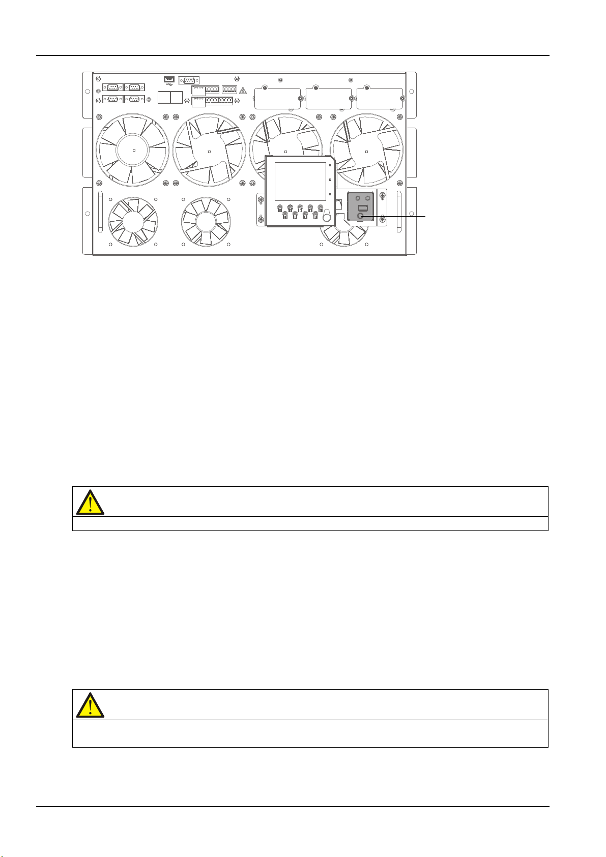
50 Chapter 5 UPS Operation Introduction
Battery cold start button
Note
In bypass mode, the load is directly fed by the mains power instead of the pure AC power from the inverter.
Caution: power supply interruption danger of the load
Before making this operation, read the information on the LCD to make sure that the bypass supply is normal and
Figure 5-2 Battery cold start button
5.3 Procedures For Transfer Between Operation Modes
5.3.1 Transfer From Normal Mode To Battery Mode
Open the external power switch to isolate the mains power and initiate the UPS on battery mode. To
transfer the UPS back to normal mode, wait for several seconds, and then close the external power switch
to re-connect the mains power to the UPS. 10 seconds later, the rectifier restarts automatically, and the
UPS works in normal mode.
5.3.2 Transfer From Normal Mode To Bypass Mode
Press the OFF key for two seconds, the inverter indicator (green) is off, and the UPS will be transferred
from normal mode to bypass mode.
5.3.3 Transfer From Bypass Mode To Normal Mode
When the UPS is in bypass mode, press the ON key for two seconds, the inverter starts up, and the
inverter indicator (green) is flashing till the inverter enters normal operation, then the UPS is transferred
from bypass mode to normal mode.
5.3.4 Transfer From Normal Mode To Maintenance Mode
The following procedures will transfer the UPS from inverter output mode to the maintenance bypass
mode.
that the inverter is synchronous with the bypass supply, so as not to risk a short interruption in power to the load.
1. Press the OFF key at least two seconds. At this point, the inverter indicator (green) turns off,
accompanied by an audible alarm. The load transfers to the static bypass, and the inverter shuts down.
Liebert NXC 60kVA UPS User Manual
Page 66
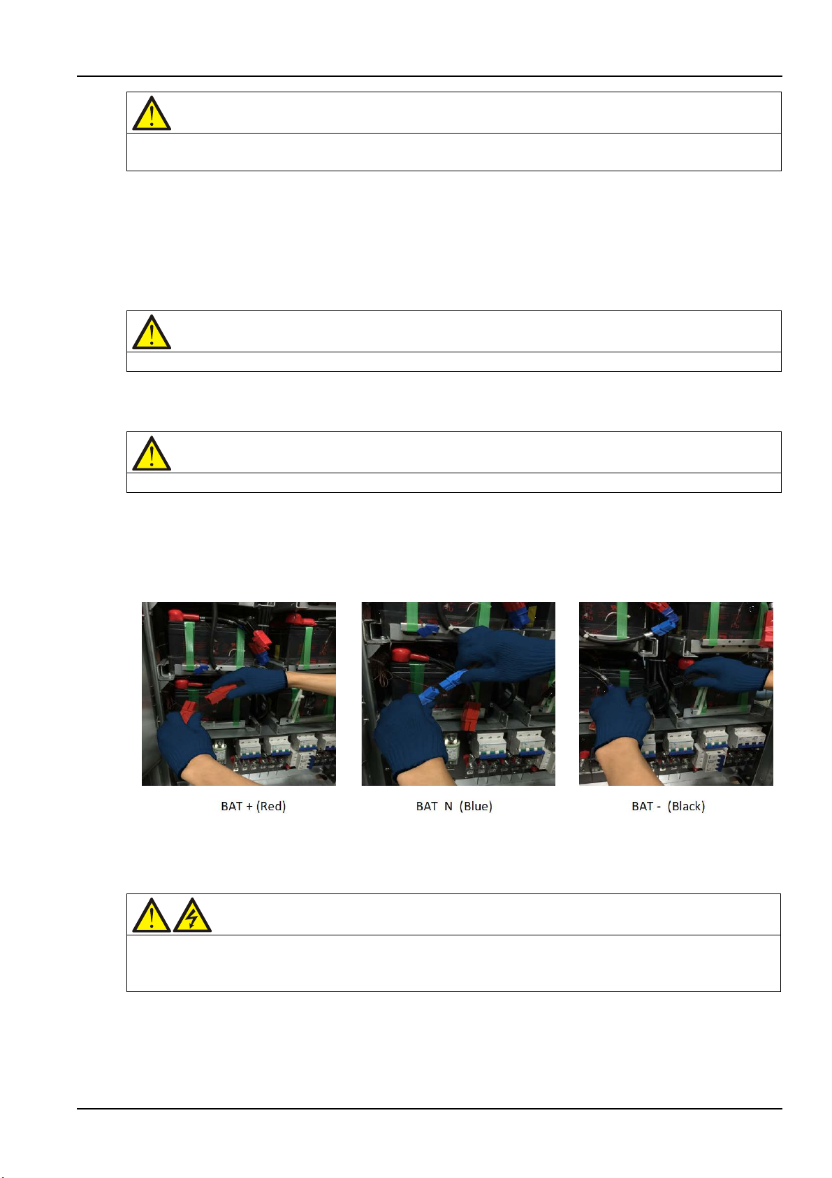
Chapter 5 UPS Operation Introduction 51
Note
Pressing the ALARM CLEAR key cancels the audible alarm but leaves the alarm message displayed until the alarm
Caution
When the UPS is in maintenance mode, the load is not protected against abnormal mains supply.
Note
In maintenance mode, the load is directly fed by the mains power instead of the pure AC power from the inverter.
Warning
1. If the maintenance is required, wait 10 minutes for the internal DC bus capacitance discharging.
ave hazardous voltage, though the rectifier input switch, bypass input switch and
condition is rectified.
2. Close the maintenance bypass switch Q3 when the UPS is in single module mode.
3. At the moment, the maintenance bypass parallels with the UPS static bypass.
4. The LCD displays 'Maint. sw. closed'.
5. Disconnect the output switch Q5 and neutral line switch Q6.
At the moment, the load is powered by the maintenance bypass directly.
6. Pressing the EPO button stops the operation of rectifier, inverter, static switch and battery, but this
action will not affect the maintenance bypass power the load normally.
7. If the UPS has internal battery, use the special tool to open the battery compartment door, then wear
arc preventive gloves to disconnect the three terminals 'BAT+' (W21, W11), 'BAT-' (W19, W08), and 'BAT N'
(W20, W10), see Figure 5-3 for details. If the UPS has external battery, disconnect the corresponding
switch of the external battery.
Figure 5-3 Schematic diagram for disconnecting terminals of the internal battery
8. Disconnect the rectifier input switch Q1 and bypass input switch Q2.
At the moment, all the internal power supply is closed and the LCD does not display any more.
2. The parts of UPS circuits also h
battery switch are disconnected. Therefore, the UPS maintenance is suitable for qualified personnel only.
5.3.5 Transfer From Maintenance Mode To Normal Mode
The following procedures will transfer the maintenance bypass supply mode of the UPS to the normal
mode.
Liebert NXC 60kVA UPS User Manual
Page 67
52 Chapter 5 UPS Operation Introduction
Warning
You must start the bypass first, and then disconnect the maintenance bypass switch; or it will cause output load
At the moment, the load has transferred to UPS normal mode.
1. Open the front door, close the neutral line switch Q6.
2. Close the output switch Q5.
3. Close the bypass input switch Q2.
4. After the LCD startup, the system will transfer to the Event menu window till the system confirms that
the record displays 'Bypass mode'.
power failure.
5. Disconnect the internal maintenance bypass switch Q3.
6. Close the rectifier input switch Q1, then the alarm indicator (red) is flashing.
7. Press the ON key for two seconds.
The inverter starts up, and the inverter indicator (green) is flashing. After the inverter runs normally, the
UPS will be transferred from the bypass to inverter, and then the inverter indicator (green) is on.
5.4 Battery Test Procedures
The battery test function is disabled by default. If you need this function, please contact the customer
service engineer of Vertiv.
Battery test type and preconditions
1. There are two battery tests to select from:
Battery maintenance test: verifies the battery integrity and leads to the battery being partly
discharged (20%).
Battery capacity test: verifies precisely the battery capacity and leads to the battery being fully
discharged (until Battery low pre-warning alarm)
2. The tests can be carried out from the operator control and display panel of the UPS by the operator
when the following conditions are satisfied:
The load must be greater than 5% of rated UPS capacity and must be stable (for battery
maintenance test)
The load must be between 20% and 80% of rated UPS capacity and must be stable (for battery
capacity test)
The battery must have been float charging for 5 hours or more before battery capacity test
The battery test procedures are password controlled and menu driven. The test is immediately terminated
in the event of a battery or a mains failure and the total load power is supported from the remaining
source without interruptions.
Test procedure
1. Select the Command menu on the LCD screen on the operator control and display panel of the UPS.
Use the right or left key to navigate to the Command menu.
2. Select the desired test (the Battery maintenance test or Battery capacity test option).
Use the up and down keys (F3, F4) to highlight the desired test. Press the Enter key (F5).
Liebert NXC 60kVA UPS User Manual
Page 68

When prompted, enter each password digit with up key (F3) and use right key (F4) to access next field.
Caution
The following procedures will cut off the load power, making the load completely power off.
Press the Enter key (F5) when all digits have been entered.
3. Wait until the test completes.
This test updates the battery information, including the battery autonomy time (battery discharge
duration during AC input failure) and the battery aging coefficient (battery capacity percentage when
compared to a new battery).
4. Stop the test.
If required, the test may be stopped before completion by selecting Stop Testing on the Command menu.
5.5 UPS Self-test Procedures
During the self-test, the UPS can check the UPS control functions, LED indicators and audible alarm
states. This self-test is password controlled and menu driven. It can be carried out from the UPS operator
control and display panel by the operator and takes five minutes.
Procedures for UPS self-test
1. Select the Command menu on the LCD screen on the operator control and display panel of the UPS.
Chapter 5 UPS Operation Introduction 53
Use the left key (F3) or right key (F4) to display the Command menu. Press the Enter key (F5) to confirm
it.
2. Select the desired test.
Use the up key (F3) or down key (F4) to highlight the desired test item. Press the Enter key (F5) to
confirm it.
After the prompt, use the up and right keys (F3, F4) to input the password, and then press the Enter key
(F5) to confirm it.
3. Wait until the test completes.
After five seconds, a pop window will appear to show the result of this diagnosis: rectifier, inverter, monitor
OK or fault.
4. Stop the test.
If required, the test may be stopped before completion by selecting Stop Testing on the Command menu.
Refer to Chapter 4 Operator Control And Display Panel for more information.
5.6 UPS Shutdown Procedures
5.6.1 Procedures For Completely Powering Down UPS
Complete UPS shutdown and load power-off should follow this procedure. All power switches, isolating
switches and breakers are disconnected, and then UPS no longer supplies power to load.
1. Pressing the EPO button stops the operation of rectifier, inverter, static switch and battery.
2. If the UPS has internal battery, use the special tool to open the battery compartment door, then pull the
three terminals 'BAT+', 'BAT-' and 'BAT N' (see Figure 5-3 for details). If the UPS has external battery,
disconnect the corresponding switch of the external battery.
Liebert NXC 60kVA UPS User Manual
Page 69
54 Chapter 5 UPS Operation Introduction
Warning
1. Post a label at the AC input distribution (generally far away from the UPS) to alert that the UPS maintenance is
Warning: hazardous battery voltage
The battery terminals still have hazardous voltage after the UPS is completely shut down.
Note
1. The rectifier will start and the bypass will begin to power the load. The rectifier indicator flashes while the rectifier
is starting up. When the rectifier enters normal operation (about 30 seconds later), the rectifier indicator turns solid
3. Disconnect the rectifier input switch Q1, bypass input switch Q2, output switch Q5. At the moment, all
the internal power supply is closed and the LCD does not display any more.
being operated.
2. Wait 10 minutes for the internal DC bus capacitance discharging. Then the UPS is completely shut down.
5.6.2 Procedures For Completely Powering Down UPS While Maintaining Power To Load
The following procedures are applicable for completely powering down the UPS and still keeping the
power supply to the load. Refer to the procedures in 5.3.4 Transfer From Normal Mode To Maintenance
Mode.
5.7 EPO Procedures
The EPO is designed to switch off the UPS in emergency conditions (that is, fire, flood, etc.). To carry out
EPO, you just need to press the EPO button, then the system will turn off the rectifier, inverter and stop
powering the load immediately (including the inverter and bypass), and the battery stops charging or
discharging.
After EPO, if the input mains is present, the UPS's control circuit will remain active; however, the output
will be turned off. To remove all power from the UPS, first disconnect the external power switch of the UPS,
and then pull the battery terminals (see Figure 5-3 for details).
5.8 UPS Reset Procedures After EPO
After shutting down the UPS through EPO or reasons of inverter overtemperature, overload, battery
overvoltage and DC bus voltage, clear the fault according to the alarm message displaying on LCD screen.
Then carry out the following reset procedures to make UPS resume normal operation.
After confirming the fault has been cleared and no remote EPO signal is received, the user can carry out
the following procedures:
1. Press the FAULT CLEAR key over two seconds, the system will exit the EPO state, and the alarm
indicator (red) is flashing.
2. Press and hold the ON key over two seconds, the inverter starts up, and the inverter indicator (green) is
flashing. After the inverter runs normally, the UPS will be transferred from the bypass to inverter, and then
the inverter indicator (green) is on.
green.
2. The rectifier will start automatically when the overtemperature fault disappears five minutes after the
disappearance of overtemperature signal.
Liebert NXC 60kVA UPS User Manual
Page 70
3. After the EPO switch is pressed, if the mains input is cut off, the UPS will shut down completely. When
Warning
If the maintenance bypass switch Q3 is closed, and UPS has input power, it means UPS has outputs.
Note
During the automatic restart process, manual startup is disabled. Automatic restart must be set by Vertiv's
the mains input returns, the UPS will start up on bypass. There will be power at the output terminals of the
UPS.
5.9 Automatic Restart
In the case of a mains failure, the UPS draws power from the battery system to supply the load until the
batteries are depleted. When the UPS reaches its EOD threshold, it will shut down.
The UPS will automatically restart and enable output power only when the following conditions are met:
1. If Auto Recovery after EOD Enabling is enabled.
2. After the Auto Recovery after EOD Delay Time expires (the default delay is 10 minutes), the UPS
restarts bypass, then inverter. During the automatic recovery delay, the UPS will charge its batteries to
provide a safety margin for equipment shutdown if input power fails again.
3. If the Auto Recovery after EOD Enabling feature is disabled, the user may restart the UPS manually by
pressing the FAULT CLEAR key first for two seconds and then ON key for two seconds.
Chapter 5 UPS Operation Introduction 55
authorized service engineer through Vertiv setting software.
5.10 Selecting Language
The LCD menu and data display is available in 17 languages: simplified Chinese, traditional Chinese,
English, Dutch, French, German, Italian, Japanese, Polish, Portuguese, Russian, Spanish, Swedish, Finnish,
Norwegian, Czech and Turkish.
Use the following procedures to select the language:
1. On the 'OutPut' menu screen, press the F3 (left) or F4 (right) key to select the 'Language' menu.
2. Press the F5 (enter) key to move the cursor to the data window of the screen.
3. Press the F3 (up) or F4 (down) key to select the desired language.
4. Press the F5 (enter) key to confirm.
5. Press the F2 (ESC) key repeatedly to return to the 'OutPut' menu.
At this point, the LCD displays all characters in the selected language.
5.11 Changing Current Date And Time
Use the following procedures to change the system date and time:
1. On the 'OutPut' menu screen, press the F3 (left) or F4 (right) key to select the 'Settings' menu.
2. Press the F5 (enter) key to move the cursor to the data window of the screen.
3. Press the F3 (up) or F4 (down) key to select the 'Date & time' item, and then press the F5 (enter) key to
confirm.
4. Press the F3 (up) or F4 (down) key to the row displaying the date and time, and press the F5 (enter)
key to confirm.
Liebert NXC 60kVA UPS User Manual
Page 71

56 Chapter 5 UPS Operation Introduction
5. Use the F3 (up) or F4 (down) key to input the current date and time.
6. Press the F5 (enter) key to confirm, and press the F2 (ESC) key to return to the 'OutPut' menu.
5.12 Control Password
The system provides password protection for UPS operation and control. The default password is '12345'.
Only enters the correct password can you execute the UPS self-test and battery test operation.
To change password, carry out the following procedures:
1. On the 'OutPut' menu screen, press the F3 (left) or F4 (right) key to select the 'Settings' menu.
2. Press the F5 (enter) key to move the cursor to the data window of the screen.
3. Press the F3 (up) or F4 (down) key to select the 'Command password' item, and press the F5 (enter)
key to confirm, then 'Command password' is changed to 'Enter old password'.
4. Press the F4 key to move the cursor to corresponding password position, and press the F3 key to select
the number from '0' ~ '9' for this position. After the five digits input, press the F5 (enter) key to confirm, at
this moment, 'Command password' is changed to 'Enter new password'.
5. Similar to step 4, press the F3 and F4 to input new password and press the F5 (enter) key to confirm, at
this moment, 'Command password' is changed to 'Enter new password again'.
6. Similar to step 4, press the F3 and F4 to input new password again, and press the F5 (enter) key to
confirm, then press the F2 (ESC) key to return to the 'OutPut' menu.
Liebert NXC 60kVA UPS User Manual
Page 72
This chapter introduces the battery, including the battery safety, installation and maintenance information,
Warning: hazardous battery voltage present behind covers
1. No user-serviceable parts are located behind covers that require a tool for their removal. Only qualified service
Too large or too small torque may cause poor connection of the
battery protection function, as well as the connection of BCB box (optional).
6.1 Introduction
The UPS battery string is composed of several batteries in series connection and provides rated DC input
voltage for the UPS inverter. The required battery backup time (i.e. the time for battery to supply load
upon mains failure) is subject to the ampere-hour value of the battery. Sometimes, it is necessary to
connect several strings of battery in parallel.
To facilitate the UPS installation, the battery is generally installed on the specially designed battery rack or
in the battery room.
During the maintenance or repair, the battery must be disconnected from the UPS. This operation may be
realized by the battery circuit breaker of proper capacity. This circuit breaker shall be located as close as
possible to the battery connecting terminal, and the wiring distance of the power and signal cables
connected to the UPS shall be minimized.
Chapter 6 Battery 57
Chapter 6 Battery
When several strings of battery are paralleled to increase the battery backup time, disconnecting device
shall be equipped, so that the maintenance operation on a certain battery string will not affect the normal
operation of other battery strings.
6.2 Safety
Take special care when working with the batteries associated with the UPS. When all the blocks are
connected together, the battery string voltage can be up to 540Vdc. This is potentially lethal. Please
follow the precautions for high voltage operation.
Only qualified personnel are allowed to install and maintain the battery. To ensure safety, the external
batteries are to be installed inside a lockable cabinet or in a purpose-designed, dedicated battery room, so
that they are only accessible to qualified service personnel.
Confirm that the battery switch has been disconnected before battery maintenance.
The NXC 60kVA UPS supports internal battery or external battery, but you must not use internal battery
and external battery together.
personnel are authorized to remove such covers.
2. Before working on the copper bars connected to the external battery, please ensure they are disconnected from
all power supplies.
Proper connection mode Improper connection mode
Tighten the terminal bolt of the
battery with specified torque
Liebert NXC 60kVA UPS User Manual
terminal. Under certain conditions, the terminal may have arcing or
heat accumulation, which finally will cause fire
Page 73
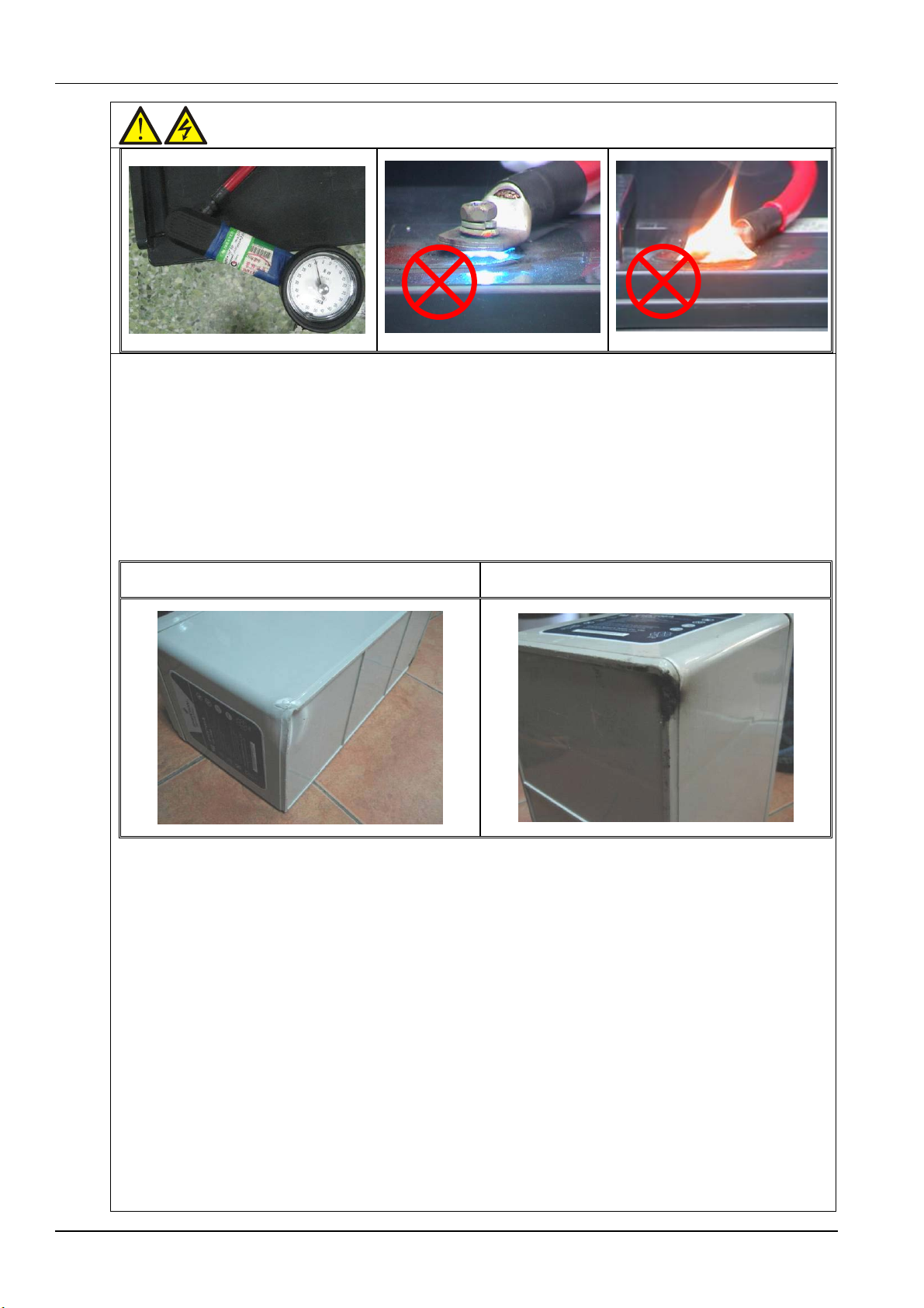
58 Chapter 6 Battery
Warning: hazardous battery voltage present behind covers
anual provided by the battery manufacturer shall be satisfied. The connections between all
the wiring terminals and the batteries shall be inspected and tightened at least once a year. Otherwise it may cause
damage, dirty battery terminal, terminal erosion, rust, or enclosure crack, deformation or liquid leakage, replace it
(e.g., wrench) are covered with insulating material. Otherwise, battery burning, human death/injury or explosion may
3. Observe the following safety precautions when working on the batteries:
a) The battery shall be firmly and reliably connected. After the connection is completed, the screw connections
between all the terminals and the batteries shall be calibrated. The requirements on torque specified in the
specifications or user m
fire!
b) The battery appearance must be inspected before accepting and using the battery. If there exists any package
with a new battery. Otherwise, battery capacity reduction, electric leakage or fire may be caused.
Battery damaged during handling or transportation After a week of normal charge/discharge experiment
c) The battery is very heavy. Please use proper method to move and lift the battery, so as to prevent any damage
to human being or the battery terminal. Severe damage to the battery may cause fire.
d) The battery connecting terminal shall not be subject to any force, such as the pulling force or twisting force of
the cable, otherwise, the internal connection of the battery may be damaged. Severe damage to the battery may
cause fire.
e) The battery shall be installed and stored in a clean, cool and dry environment. Do not install the battery in a
sealed battery chamber or a sealed room. The battery room ventilation shall at least meet the requirement of
EN50272-2001. Otherwise, battery bulging, fire or even human injury may be caused.
f) The battery shall be installed far away from the heating products (e.g. transformer), used or stored far away from
any fire source, and shall not be burnt or put into fire for heating. Otherwise, battery leakage, bulging, fire or
explosion may be caused.
g) Do not directly connect any conductor between the positive and negative terminals of the battery. Remove the
finger rings, watch, necklace, bracelet and other meta items before operating the battery, and ensure that the tools
be caused.
h) Do not disassemble, modify or demolish the battery. Otherwise, battery short circuit, liquid leakage or even
human injury may be caused.
Liebert NXC 60kVA UPS User Manual
Page 74
Warning: hazardous battery voltage present behind covers
i) Clean the battery enclosure with the wringed wet cloth. To avoid any static or arcing, do not use dry cloth or
duster to clean the battery. Do not use the organic solvent (such as thinner, gasoline, volatile oil) to clean the
battery. Otherwise, the battery enclosure may be cracked. In worst case, fire may be caused.
j) The battery has diluted sulfuric acid. In normal use, the diluted sulfuric acid will be absorbed to the baffle and
polar plate of the battery. However, if the battery is damaged, the acid may leak from the battery. Therefore,
personal protective equipment (e.g., protective glasses, rubber gloves and apron) must be used when operating the
battery. Otherwise, if the diluted sulfuric acid enter the eyes, blindness may be caused; if it contacts the skin, the
skin may be burnt.
k) The battery may have short circuit, electrolyte dry-up or positive pole erosion failure at the end of its life. If it is
still used under this state, the battery may have thermorunaway, bulging or liquid leakage. Please replace the
battery before it becomes this state.
l) Before connecting or disconnecting the battery connection cables, please isolate the charging power.
m) Check if the battery has been unexpectedly earthed. If this is the case, remove the earth connection. Contact
with any part of the earthed battery may result in an electric shock.
6.3 UPS Battery
Chapter 6 Battery 59
The UPS generally adopts valve-regulated battery. At present, 'valve-regulated' means the 'sealed type' or
'maintenance free' mentioned in the past.
The valve-regulated battery is not completely sealed, especially when it is over-charged, there will be gas
escape. The volume of the gas escape is less than the water injection battery. However, during the
installation design of the battery, temperature rise shall be taken into account, and enough room shall be
reserved to ensure good ventilation.
Besides, the valve-regulated battery is not maintenance free. The valve-regulated battery must be kept
clean, and it shall be inspected regularly to check if the connection is reliable, and if it is corroded. For
details, please refer to 6.11 Battery Maintenance.
It is suggested to connect no more than 4 strings of batteries in parallel. Batteries of different types,
names or newness shall not be used together. Otherwise, the battery inconsistency will cause frequent
over-discharge or under-charge of certain battery. At last, the battery will have premature failure, and the
entire string of battery will have insufficient backup time.
The battery must be stored in fully charged state. The battery will lose certain capacity because of self
discharge during the transportation or storage. Charge the battery before use. During the storage, ensure
that the ambient temperature shall not exceed the range of -15°C ~ +45°C, and the optimal temperature is
20°C ~ 25°C. To compensate for the self discharge of the battery during the storage, the battery shall be
charged every 3 months during the storage. The specific time may differ for different batteries. For details,
refer to the requirement of the battery manufacturer.
It is important to fully charge the battery before carrying out onsite test on the battery backup time. The
test may take several days. Therefore, it should be conducted after the battery has been subject to
uninterrupted float charging for at least one week.
When the battery has been running for several weeks or subject to two to three charge and discharge
cycles, the battery performance will be increased.
To avoid the battery over-charge or under-charge, please set the battery management parameters
according to the equalizing/float charge voltage and temperature compensation factor specified in the
manuals provided by the battery manufacturer. Please charge the battery immediately after discharge.
Liebert NXC 60kVA UPS User Manual
Page 75
60 Chapter 6 Battery
Note
1. Precautions for installation, use and maintenance of the battery are described in the relevant battery manual
Typ e
Temperature
value
Remark
Recommended
The ambient temperature for the battery operation shall not be too high
6.4 Precautions For Installation Design
provided by the battery manufacturer.
2. The safety precautions described in this section include the important matters that must be considered during
the installation design.
3. The design results may be changed according to the local situations.
6.5 Battery Installation Environment And Number Of Batteries
6.5.1 Installation Environment
Fresh air volume (EN50272-2001)
The operating environment of the battery must be ventilated. During the operation of the battery, the
following requirement for the fresh air ventilation shall be satisfied:
Q=0.05 x n x I
x Crt x 10–3[m3/h]
gas
Where:
3
Q―The fresh air ventilation volume per hour, the unit is m
/h
n―Number of cells
―The gas evolving current density under battery float charging or boost charge conditions, the unit is
I
gas
mA/Ah
I
=1, under the float charging condition of 2.27V/cell
gas
=8, under the boost charge condition of 2.35V/cell
I
gas
―20hr battery rated capacity
C
rt
Temperature
Table 6-1 Ambient temperature range
optimal
temperature
Short time
allowable
temperature
20°C ~ 25°C
~ 45°C
-15
°C
or too low.
If the average operating temperature of the battery rises from 25°C to
, the service life of the battery will be reduced by 50%. If the
35
°C
operating temperature of the battery is over 40
battery will be reduced exponentially each day
, the service life of the
°C
The higher the temperature is, the shorter the battery service life will be. At low temperature, the
charge/discharge performance of the battery will be significantly reduced.
The battery must be installed in cool and dry environment with the humidity less than 90%, and be
protected from the heat source and direct sunshine.
The ambient temperature, ventilation, space, float/boost charge voltage and ripple current will affect the
battery temperature. Uneven temperature among the battery strings will cause uneven voltage
distribution and thus result in problem. Therefore, it is very important to maintain balanced temperature in
the battery string, and the temperature difference between batteries of different layers shall be kept
Liebert NXC 60kVA UPS User Manual
Page 76
within 3°C. Valve-regulated battery is very sensitive to the temperature, therefore, valve-regulated battery
Parameter
380V/4 0 0V/41 5 V
Number of cells (standard)
180 ~ 240
EOD voltage
1.60Vdc/Cell ~ 1.85Vdc/Cell, 1.63V/cell recommended
Float charging voltage
2.2Vdc/Cell ~ 2.3Vdc/Cell, 2.27V/cell recommended
Note
Only trained personnel shall operate and maintain the battery circuit breaker.
shall be used in 15°C ~ 25°C. If the battery cabinet is installed near the UPS, the maximum design ambient
temperature shall be determined according to the battery rather than the UPS. That is, if valve-regulated
battery is used, the indoor ambient temperature shall be 15°C ~ 25°C rather than the operating
temperature range of the main equipment. Under the precondition that the average temperature will not
exceed 25°C, it is allowed to have short time temperature deviation.
6.5.2 Number Of Batteries
The number of batteries, EOD voltage, and float charging voltage under the 380V/400V/415V voltage
system are consistent, as shown in Table 6-2.
6.6 Battery Protection
Chapter 6 Battery 61
Table 6-2 Number of batteries
The UPS inside has a fuse switch to protect the internal battery. The Vertiv BCB (optional) is
recommended to protect the external battery.
The external battery is connected to the UPS through the BCB. The BCB can be manually closed and has
the electronic tripping device controlled by the UPS control circuit. If the battery adopts rack mounting
(or is far away from the UPS cabinet), the BCB shall be installed as close to the battery as possible, and
the wiring distance of the power and signal cables connected to the UPS shall be minimized.
The BCB has the following features:
Isolated with the battery, safe and reliable
Short circuit protection
In case the inverter is locked because of battery under-voltage, the circuit breaker will be
disconnected
automatically to avoid battery over-discharge
If remote EPO button is installed, the EPO button can be used to disconnect the circuit breaker
Mis-operation protection
To obtain the required backup time, the batteries may be connected in parallel. In this situation, the BCB
shall be installed in the after-stage of all the paralleled batteries.
6.7 Battery Installation And Connection
6.7.1 Battery Installation
1. Before installation, check the battery appearance to ensure that there is no damage, inspect and count
the accessories, and carefully read this manual and the user manual or installation instruction provided by
the battery manufacturer.
Liebert NXC 60kVA UPS User Manual
Page 77

62 Chapter 6 Battery
2. There shall be at least 10mm gap between the batteries in vertical direction, to ensure the free
circulation of the ambient air of the batteries.
3. Certain clearance shall be maintained between the battery top and the upper layer to facilitate the
monitoring and maintenance of the battery.
4. The batteries shall be installed from the bottom layer and from bottom to top, so as to avoid a too high
gravity center. The battery shall be properly installed and protected from vibration or shock.
6.7.2 Battery Connection
1. All the battery cabinets or battery racks must be connected together and properly grounded.
2. When multiple batteries are used, they shall be connected in series and then in parallel. Before loading
and power-up, it must be detected that the total voltage of the batteries is as specified. The negative and
positive poles of the batteries must be connected to the negative and positive battery terminals of the
UPS according to the labels on the battery and UPS. If the battery is reversely connected, explosion and
fire may be caused, it may result in battery and UPS damage or even human injury.
3. When the battery cable connection is completed, install insulating shield for the terminals.
4. When connecting the cable between the battery terminal and the BCB, the BCB terminal shall be
connected first.
5. The bending radius of the cable shall be larger than 10D, wherein D is the outer diameter of the cable.
6. When the battery cable is connected, it is prohibited to pull the battery cable or the cable terminal.
7. Do not cross the battery cables during the connection, and do not tie the battery cables together.
8. See Figure 6-1 for battery connection.
Liebert NXC 60kVA UPS User Manual
Page 78
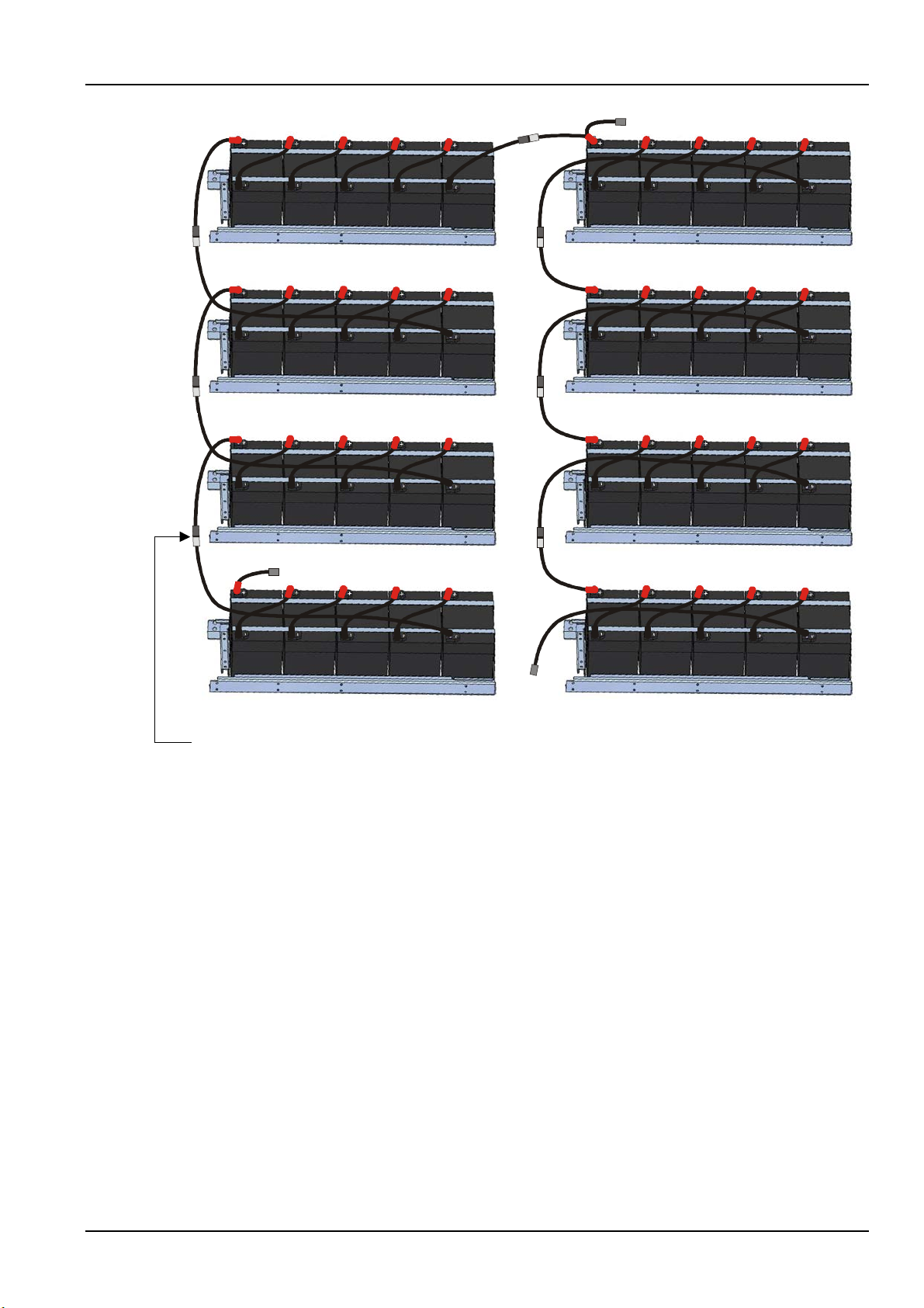
Chapter 6 Battery 63
W04
W15
W10
BAT-N
W14
W03
W13
W02
W12
W01
W11
BAT +
Battery tray 2
Battery tray 3
Battery tray 4
Battery tray 5
Battery tray 6
Battery tray 7
Battery tray 1
Battery tray 8
PP terminal of W01 connects to PP terminal of W12
W05
W16
W06
W17
W07
W18
W08
BAT-
w09 w09 w09 w09 w09 w09 w09
w09
Figure 6-1 Connection for internal batteries (40-block)
6.8 Design Of Battery Room
No matter which type of installation system is adopted, the following items shall be paid special attention
to (refer to Figure 6-2):
Layout of cells
No matter which battery installation system is used, the battery shall be located in a matter that it will not
contact two naked live parts with the potential difference over 150V at the same time. If it is unavoidable,
insulated terminal shield and insulated cable shall be used for the connection.
Workbench
The workbench (or pedal) must be skid-proof and insulated, and at least 1m wide.
Wiring
All the wiring distances shall be minimized.
BCB
The BCB is generally installed in the wall-mounted box near the battery.
Liebert NXC 60kVA UPS User Manual
Page 79
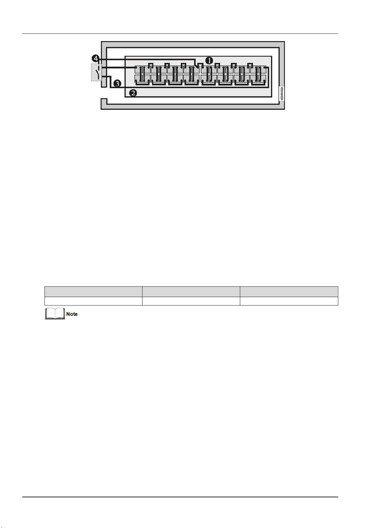
64 Chapter 6 Battery
Dimensions (H × W × D) (mm)
Weight (kg)
BCB
192 × 380 × 636
13
200A, 4 poles
6.9 BCB Box (Optional)
The BCB box contains a BCB and a BCB control board.
Vertiv provides the BCB box and BCB signal cables (length: 30m) for use when the battery does not install
in the battery cabinet. In this situation, The BCB box is fitted as close as possible to the battery and
connected to the UPS. Refer to Figure 6-3 and Table 6-4 for description of the BCB box and its
components.
The BCB box protects the battery against overdischarge and overcurrent, and also isolates the UPS and
battery, thus reducing the risk at lowest for service personnel during the maintenance. The box inside has
connection bars for connecting the power cables from the UPS and batteries.
Figure 6-2 Design of battery room
Note: The signal cables from the UPS to the BCB control board must be routed in a separate cable
trough and separated from battery power cables. The separate safety earth must be connected
between the UPS and BCB box.
The BCB box is provided as follows according to different UPS rated power.
Table 6-3 Parameters of BCB box
This weight excludes the packing.
Liebert NXC 60kVA UPS User Manual
Page 80
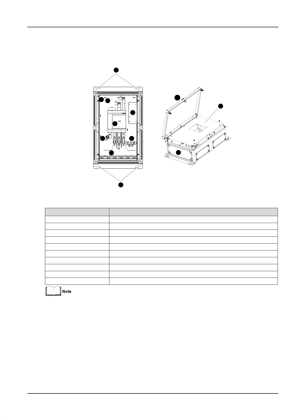
Chapter 6 Battery 65
UPS+
UPS-
UPS N
BAT N
BAT+
BAT-
1
3
4
2
5
6
7
9
8
10
2
6
No.
Component
1
Battery connection terminal (+/N/-)
2
UPS connection terminal (+/N/-)
3
Battery switch control board
4
Battery switch
5
Cabling hole for confirming the cable size and opening hole
6
Wall-mounted installation hole
7
Grounding bar
8
Insulating plate
9
Base plate
10
Visible cover
The BCB has the following advantages:
Short circuit protection and EOD protection. When the battery voltage drops to EOD, the BCB will be
switched off automatically.
UPS EPO. When pressing the EPO button, the BCB will be switched off automatically.
Figure 6-3 BCB box
Table 6-4 Description of BCB box components
The BCB box generally uses bottom cabling mode, but you can rotate its bottom plate to use top cabling mode.
Liebert NXC 60kVA UPS User Manual
Page 81
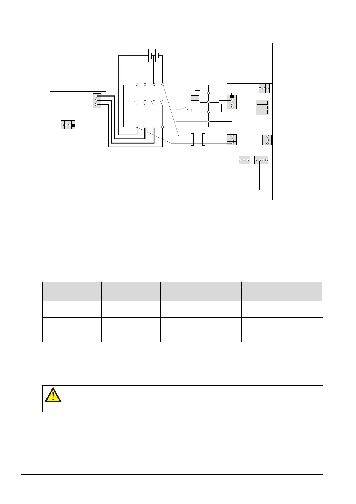
66 Chapter 6 Battery
~
External battery string
UPS
Battery
input
terminal
Communicati on
box
+
N
-
BCB
UV
Auxiliary
contactor
OUT-P
OUT-N
AUX 1
AUX 2
BCB control board
X103
X104
X105
X106
X107
X108 X102
X101
1
2
3
GND1
AUX
DRV
CND
F8
DRV
220Vdc
Note:
1.See Table 6-5 for definition of port X102.
2.X101-Hazardous Voltage: Do not connect this port to the battery unless a permission given by the service engineer.
3.X103~X106 are used to connect temperature sensors from multiple battery cabinets.
4.X107 is used to set jumpers according to whether the UPS has been installded a battery cold button.
If yes, jumpers 1,2setting is recommended ; if not,jumpers 2,3 setting is required
X100
GND
4. X107 is used to set jumpers according to whether the UPS has been installded a battery cold button
If yes, jumpers 1, 2 setting is recommended; if not, jumpers 2, 3 setting is required.
BCB box port
Meaning
Signal state
Tripping control signal of BCB
Normal: high level, BCB closed;
Auxiliary contact of BCB
Normal: 0V, BCB closed;
GND1
GND
Signal ground
GND1 to GND
Caution
If the corresponding functions are not required, just do not connect corresponding ternimals.
J2
Figure 6-4 Connection of BCB box
Table 6-5 Battery control port (X102)
Communication box
port (J2)
DRV DRV
IN (AUX) FB (IN)
Note: The cable of the X102 BCB port must be routed separately from the power cable. It uses the
dual-insulated shielded cable (the CSA is generally 0.5mm
length), and the two ends of the shielding coat must be connected to the enclosure reliably. The separate
safety earth must be connected between the UPS and BCB box.
6.10 BCB Reference Current And Connection
Table 6-6 provides recommended BCB rated current and battery maximum discharge current at full load.
from the UPS
(contact off means BCB off)
Abnormal: low level, BCB open
Abnormal: open, BCB open
2
~ 1mm2 when the wiring distance is 25m ~ 50m
Refer to Table 3B in IEC60950-1, and select the appropriate cable CSA according to local electrical
regulations.
Liebert NXC 60kVA UPS User Manual
Page 82
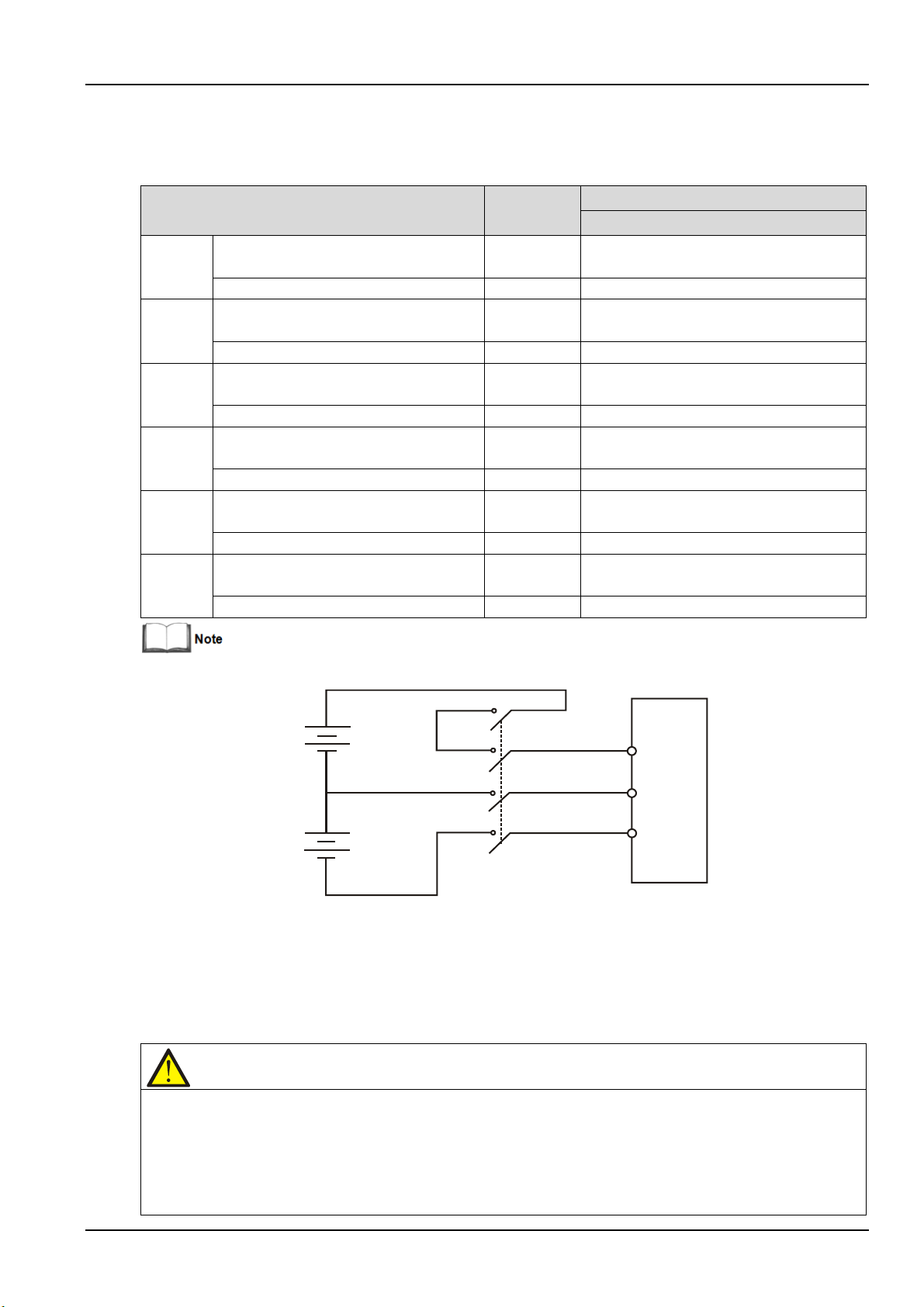
Chapter 6 Battery 67
Item
Unit
UPS rating (kVA)
60kVA
30-bloc
Max. battery discharge current at full
Reference rated current of BCB
A
200
Max. battery discharge current at full
Reference rated current of BCB
A
200
Max. battery discharge current at full
Reference rated current of BCB
A
200
Max. battery discharge current at full
Reference rated current of BCB
A
200
Max. battery discharge current at full
Reference rated current of BCB
A
200
40-bloc
Max. battery discharge current at full
Reference rated current of BCB
A
200
+
N
-
+
N
-
UPS
N
N
UPS
Note
1. Periodically check the screws of the battery connection parts and confirm that they are firmly tightened. If there is
hat all safety devices are in place and operate normally, and that the battery management parameters are
Table 6-6 BCB rated current and battery max. discharge current at full load (recommended)
k
battery
32-block
battery
34-bolck
battery
36-block
battery
38-block
battery
k
battery
Refer to Figure 6-5 for the connections between the battery, BCB and UPS.
load
load
load
load
load
load
A 195
A 170
A 160
A 150
A 140
A 135
Figure 6-5 Connections between the battery, BCB and UPS
6.11 Battery Maintenance
For the battery maintenance and maintenance precautions, refer to IEEE-Std-1188-2005 and the relevant
manuals provided by the battery manufacturer.
any loosened screw, tighten it immediately.
2. Ensure t
set properly.
3. Measure and record the air temperature inside the battery room.
4. Check to ensure that the battery terminals have no damage or heat generating trace, and the battery enclosure
Liebert NXC 60kVA UPS User Manual
Page 83

68 Chapter 6 Battery
and terminal shields are intact.
6.12 Disposal Of Used Battery
If the battery has liquid leakage or is damaged, place the battery into the container that can withstand
sulphuric acid and discard it according to the local regulations.
Used lead acid storage battery belongs to dangerous waste, and it is a key item for used battery pollution
control. The storage, transportation, use and disposal of the battery shall comply with the national and
local laws and regulations on dangerous waste and used battery pollution prevention and other standards.
According to the relevant national regulations, the used lead acid storage battery must be recycled and
shall not be disposed of with other methods. Random discard or any other improper disposal of the used
lead acid storage battery may cause severe environment pollution and the relevant person will be
investigated of corresponding legal responsibilities.
Liebert NXC 60kVA UPS User Manual
Page 84
Chapter 7 Parallel System And LBS System
Warning
To guarantee the normal operation of parallel system, the CAN resistance matching operation must be executed
Warning
To achieve coordinated operation of the modules in the parallel system, it is required to configure each module
This chapter gives details on the installation of parallel system and LBS system.
7.1 General
The parallel system can comprise of up to four UPS modules of the same power rating and connected in
parallel without the need for a centralized mains static bypass. Instead the bypass static switches of each
UPS share the load when the system transfers to the mains bypass supply.
From a 'power' viewpoint, each module is internally identical to the 'single module' configuration. A parallel
system requires inter-module control signals to manage the load sharing, synchronizing and bypass
switching. The control signals are connected through the parallel cables, which are multi-way ribbon
cables connected between the units of the system to form a ring.
When two or more modules are to be connected in parallel, it is recommended that the inductor should be
inserted in the static bypass line. This can be installed internal to the UPS as an option.
Chapter 7 Parallel System And LBS System 69
7.2 System Installation Procedures
The basic installation procedure of a parallel system comprising two or more UPS modules is the same as
that of single module system. This section only introduces the installation procedures specific to the
parallel system. The installation of a parallel UPS should follow the installation procedure for a single UPS
module with the additional requirements detailed in this section.
by the Vertiv authorized service engineers. Failure to do so could cause system fault.
7.2.1 Preliminary Checks
Be sure that the options of the parallel cables are correct, and that the modules are of the same rating,
model, and with the same software and hardware release.
separately using Vertiv setting software. This must be done by Vertiv service personnel.
7.2.2 Cabinet Installation
Place the UPS modules side by side and interconnect them as shown in Figure 7-1. The output distribution
mode (Q1EXT, Q2EXT must be configured) shown in Figure 7-1 is recommended to facilitate maintenance
and system testing.
Liebert NXC 60kVA UPS User Manual
Page 85
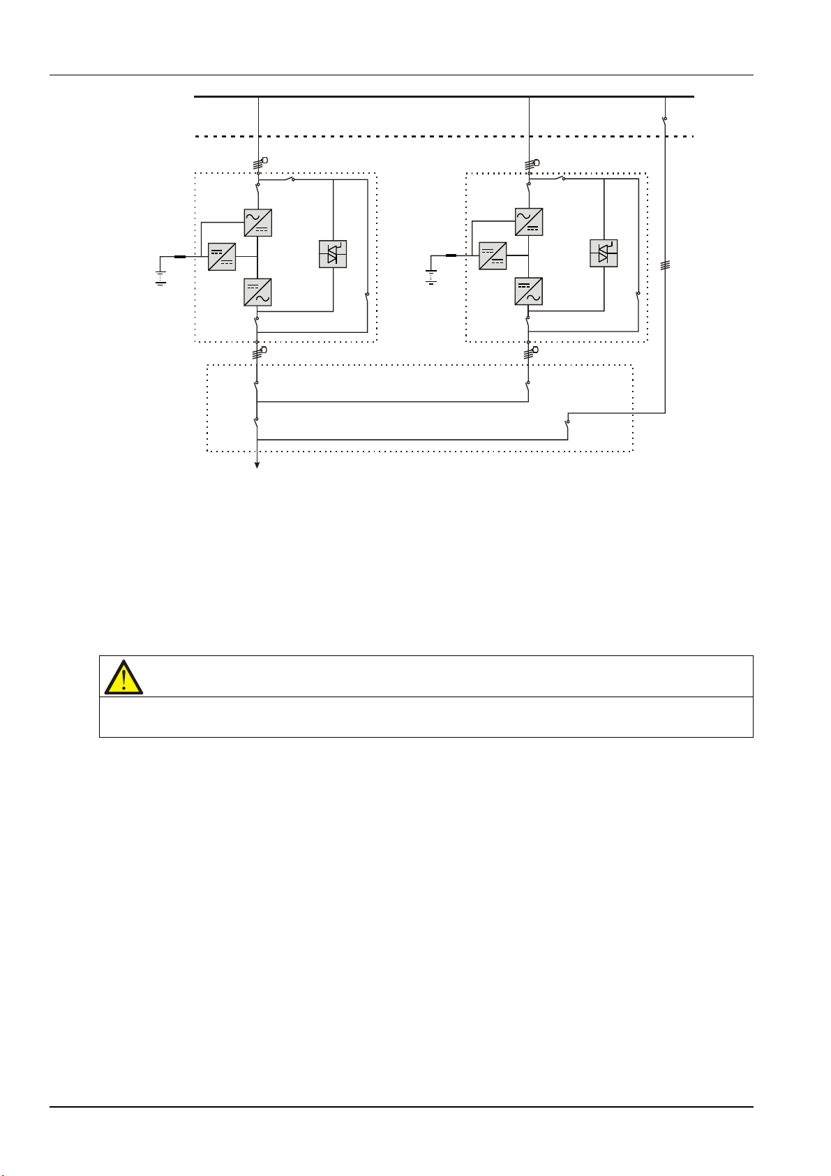
70 Chapter 7 Parallel System And LBS System
Other power supply
Mains input
L1,L2,L3,N
Fuse
Battery 1
Rectifier
Charger
Inverter
Static
switch
Q1
Q5&Q6
Q1EXT
QUPS
L1, L2,L3,N
To load
Q3
Output distribution
Q1
Q3
L1,L2,L3,N
Q2EXT
QBYP
Battery 2
Q2
Q5&Q6
Q2
External
Inverter
Fuse
Charger
Rectifier
Static
switch
Mains input
L1,L2,L3,N
bypass
switch
External maintenance bypass
Note
The power cables (including the bypass input cables and UPS output cables) of each UPS module should be of the
7.2.3 Power Cable
The power cable wiring is similar to that of the UPS module. Refer to 3.1 Wiring Of Power Cable.
The bypass and rectifier input supplies must use the same neutral line input terminal. If the input has a
current leakage protective device, the current leakage protective device must be fitted upstream of the
neutral line input terminal.
same length and specifications to facilitate load sharing.
7.2.4 Parallel Cable
Shielded and double-insulated parallel cables available in lengths 5m, 10m and 15m must be
interconnected in a ring configuration between the UPS modules, as shown in Figure 7-2. Method: connect
a module parallel cable from its PARA1 port to the PARA2 port of another module. Follow this method to
connect other parallel cables.
The ring connection ensures the reliability of the control of the parallel system. Be sure to verify the
reliable cable connection before starting up the system!
Figure 7-1 Schematic of typical parallel system (with common input, separate batteries and output)
Liebert NXC 60kVA UPS User Manual
Page 86
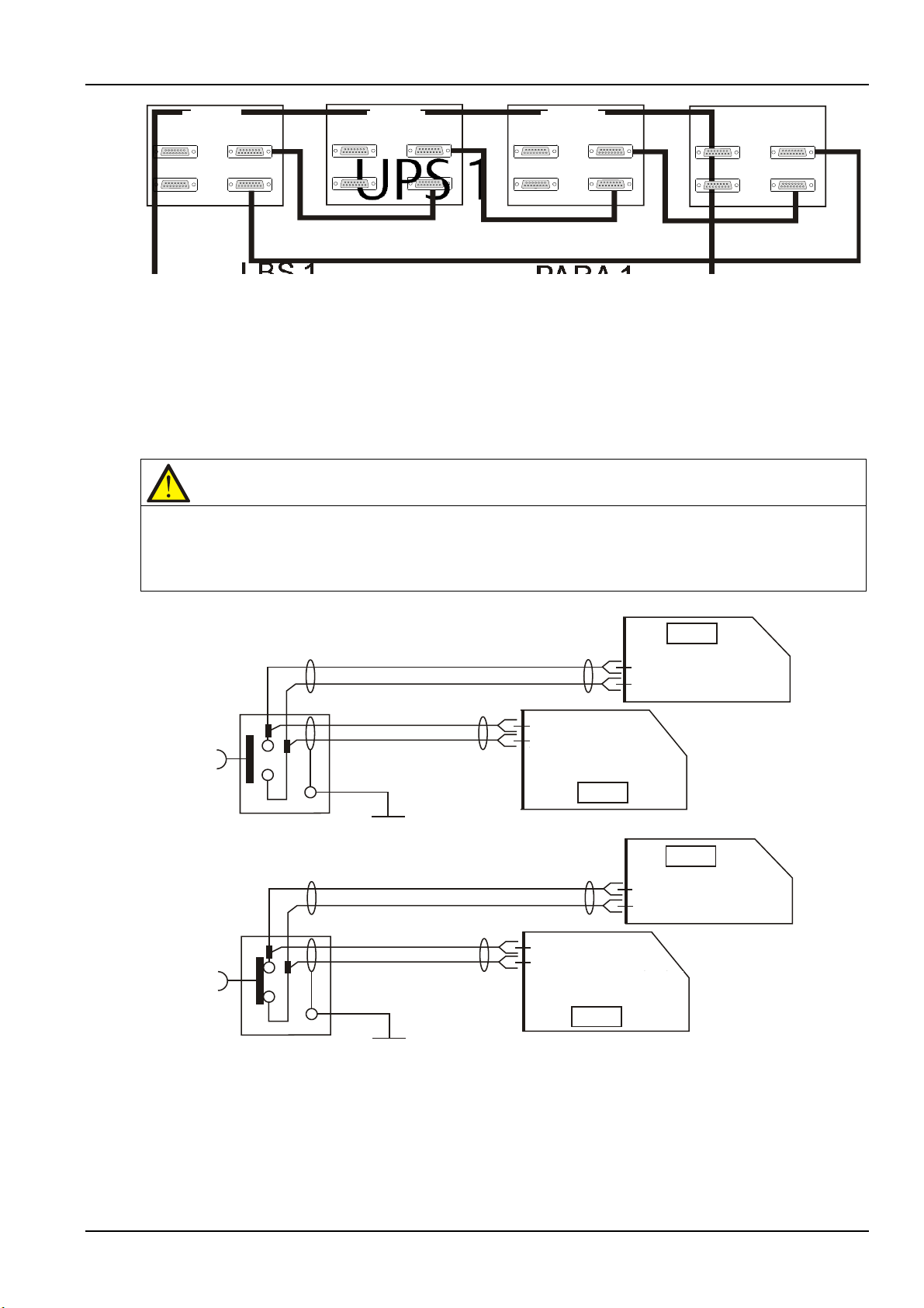
UPS 1
UPS 2
UPS 3
UPS 4
LBS 1
PAR A 1
LBS 2
PAR A 2
LBS 1
LBS 2
PAR A 1
PAR A 2
LBS 1
LBS 2
PAR A 2
LBS 1
LBS 2
PAR A 1
PAR A 2
PAR A 1
UPS 1
UPS 2
UPS 3
UPS 4
UPS 1 UPS 2
UPS
3 UPS 4
7.2.5 Remote EPO
Note
1. The remote EPO switch must provide dry contact signal, which is normally open or normally closed.
J3 3.3
EPO
UPS1
EPO
UPS 2
UPS1
UPS 2
J3 3.4
J3 3.3
J3 3.4
J3 3.1
J3 3.2
J3 3.1
J3 3.2
board
Communication
Communication
board
Communication
board
Communication
board
UPS 2
J3 3.3
J3 3.4
Communication
board
J3 3.3
J3 3.4
Communication
board
UPS 1
UPS 2
J3 3.3
J3 3.4
Communication
board
UPS 1
J3 3.3
J3 3.4
Communication
board
EPO
EPO
J4 4.3
J4 4.4
J4 4.3
J4 4.4
J4 4.1
J4 4.2
J4 4.1
J4 4.2
In addition to the EPO switch provided on the operator control and display panel of each UPS module for
controlling the EPO of each module respectively, the parallel system also provides remote EPO function
for controlling all UPS modules to shut down simultaneously from a remote terminal, as shown in Figure
7-3.
Chapter 7 Parallel System And LBS System 71
Figure 7-2 Parallel signal cables connection (Parallel system)
2. The open circuit voltage provided is 12Vdc, < 20mA.
3. The external EPO device can be composed of another control system which can disconnect UPS mains supply or
bypass input.
Figure 7-3 EPO circuit diagram
Note: In Figure 7-3, the upper one is Normally Open type, and the lower one is Normally Closed type.
Liebert NXC 60kVA UPS User Manual
Page 87
72 Chapter 7 Parallel System And LBS System
Warning
If UPS input uses RCD, differential switch is only used in the system's bypass mains supply. At the moment of
Warning
1. These procedures result in mains voltage being applied to the UPS output terminals.
Warning
To avoid misreporting as faults, all operations relating to disconnection or connection of the maintenance bypass
7.3 Operation Procedures For Parallel System
electrical connection, current may not be immediately separated, which may result in the tripping of RCCB
respectively.
Only one step is needed for once, and only after finishing this operation step of each UPS module, the next
step can be carried on.
7.3.1 Startup Procedures In Normal Mode
These procedures are used to start the UPS under total power-down state, which means the UPS or the
maintenance bypass switch has not supplied the load before. Make sure UPS has been completely
installed and commissioned by the engineer, and external power supply switch has been turned off.
2. If any load equipment is connected to the UPS output terminals, check with the user that it is safe to apply power.
If the load is not ready to receive power, disconnect the downstream load switch, and stick a warning label on the
connection point of the load.
Use the following procedures to turn on the UPS from a fully powered down condition.
1. Confirm that the total external maintenance bypass switches are disconnected. Open the front door of
each UPS in turn, ensure that the internal maintenance bypass switch Q3 is disconnected and switch Q6
is closed, while the input cables and copper bars are reliably connected, and the parallel cables are firmly
connected.
switch shall be finished within three seconds.
2. Close the total bypass input switches.
3. Close the bypass input switch Q2, rectifier input switch Q1, output switch Q5 and all external output
isolating switches (if any) of each UPS in turn.
At the moment, the system is powered on, and the startup screen pops up. Refer to 4.2.1 Start Screen.
About 25 seconds later, confirm that the LCD shows the rectifier power supply and the bypass power
supply are normal; if not, check whether the switches Q1 and Q2 are closed and the parallel cables of each
UPS are connected reliably. Then the rectifier starts up and the alarm indicator (red) is on, at the same
time, the bypass static switch is closed. About 30 seconds later, the alarm indicator (red) is flashing, then
the rectifier startup is finished. After all the rectifiers startup of the UPSs is finished, the alarm indicators
(red) are flashing.
Liebert NXC 60kVA UPS User Manual
Page 88
4. For each UPS, press the ON key for two seconds. The inverter starts up, and the inverter indicator
Warning
If the UPS system is composed of more than 2 parallel UPS modules, and the load capacity exceeds the single
Caution: power supply interruption danger of the load
Before performing this procedure, you should check the LED information first, and make sure the bypass is normal
Note
Press the ALARM CLEAR button can silence the alarm, but the alarm message of the the LCD does not disappear
Caution
When the UPS is in maintenance mode, the load does not have the mains abnormal protection.
Note
In maintenance mode, the load is directly fed by the mains power instead of the pure AC power from the inverter.
(green) of each UPS is flashing. After all the UPS inverter indicators turn solid green, the whole UPS
system will power the load.
7.3.2 Maintenance Bypass Procedures
module capacity, do not use the internal maintenance bypass switch.
This operation will make the load transfer from UPS power supply protection state to direct connection
with AC input bypass state.
and inverter synchronized. Otherwise, it may result in the load power interruption for a while.
1. Press the OFF key of each UPS in turn for two seconds. The inverter indicators are off and the buzzer
alarms. The inverter shuts down. At last, all UPSs are transferred to load supply mode.
Chapter 7 Parallel System And LBS System 73
until the alarm status is cleared.
2. Close the UPS external total maintenance bypass switches, and do not close the internal maintenance
bypass switch Q3 of each UPS.
3. At this moment, the external total maintenance bypass should be connected in parallel with each UPS's
static switch.
4. At this moment, the LCD of each UPS displays 'Maint. sw. closed'.
5. Disconnect the output switch Q5 and neutral line switch Q6 of each UPS in turn, and the maintenance
bypass can supply power to the load.
6. Pressing the EPO button of each UPS stops the operation of rectifier, inverter, static switch and battery,
but this action will not affect the maintenance bypass power the load normally.
7. If the UPS has internal battery, use the special tool to open the battery compartment door, then pull the
three terminals 'BAT+', 'BAT-' and 'BAT N' (see Figure 5-3 for details). If the UPS has external battery,
disconnect the corresponding switch of the external battery. All UPS modules should be disconnected
from the batteries.
8. Disconnect the rectifier input switch Q1 and bypass input switch Q2 of each UPS in turn.
At the moment, all the internal power supply is closed and the LCD does not display any more.
Liebert NXC 60kVA UPS User Manual
Page 89
74 Chapter 7 Parallel System And LBS System
Warning
1. If the maintenance is required, wait 10 minutes for the internal DC bus capacitance discharging.
Important
These procedures shall only be carried out by service personnel of Vertiv or under their guidance.
Warning
Before operation, confirm that the system capacity has redundancy to avoid system shutdown due to overload.
Warning
1. Post a label at the AC input distribution (generally far away from the UPS) to alert that the UPS maintenance is
Important
These procedures shall only be carried out by service personnel of Vertiv or under their guidance.
2. The parts of UPS circuits also have hazardous voltage, though the rectifier input switch, bypass input switch and
battery switch are disconnected. Therefore, the UPS maintenance is suitable for qualified personnel only.
7.3.3 Procedures For Isolating One UPS Module From Parallel System
The following procedures apply when one UPS module must be isolated from the parallel system for repair
due to serious fault:
1. Pressing the EPO button stops the operation of rectifier, inverter, static switch and battery, but this
action will not affect other UPSs in parallel system to power the load normally.
2. If the UPS has internal battery, use the special tool to open the battery compartment, then pull the three
terminals 'BAT+', 'BAT-' and 'BAT N' (see Figure 5-3 for details). If the UPS has external battery, disconnect
the corresponding switch of the external battery.
3. Disconnect the rectifier input switch Q1 and bypass input switch Q2, and disconnect the output switch
Q5 and neutral line switch Q6.
At the moment, all the internal power supply is closed and the LCD does not display any more.
being operated.
2. Wait 10 minutes for the internal DC bus capacitance discharing. Then the UPS is completely shut down.
7.3.4 Procedures For Inserting One Isolated UPS Module In Parallel System
The following procedures are used to reintegrate a UPS module that has been previously isolated from
the parallel system:
1. If the UPS is connected with a battery, just close the battery external distribution switch or three
terminals 'BAT+', 'BAT-' and 'BAT N' (see Figure 5-3 for details). Then close the rectifier input switch Q1
and neutral line switch Q6.
At the moment, the system is powered on, and the startup screen pops up. Refer to Refer to 4.2.1 Start
Screen.
2. Close the bypass input switch Q2.
At this moment, confirm that the LCD shows the bypass input supply is normal; if not, check whether the
switch Q2 is closed. Then the rectifier starts up and the alarm indicator turns solid red. About 30 seconds
Liebert NXC 60kVA UPS User Manual
Page 90
later, the alarm indicator (red) is flashing (if the UPS has internal or external battery not connected) or off
Caution
The following procedures will cut off the load power, making the load completely power off.
Warning
1. Post a label at the AC input distribution (generally far away from the UPS) to alert that the UPS maintenance is
Warning: hazardous battery voltage
The battery terminals still have hazardous voltage after the UPS complete shutdown.
(if the UPS has internal or external battery connected).
3. Close the output switch Q5, and press the ON key for two seconds.
The inverter starts up, and the inverter indicator (green) is flashing. After the inverter runs normally, the
inverter indicator turns solid green, and the inverter supplies power to the UPS.
At this point, the UPS will join the operation of the parallel system, and supply power to the load.
7.3.5 Procedures For Completely Powering Down UPS
Complete UPS shutdown and load power-off should follow this procedure. All power switches, isolating
switches and breakers are disconnected, and then UPS no longer supplies power to the load.
1. Pressing the EPO button of each UPS stops the operation of rectifier, inverter, static switch and battery.
2. If the UPS has internal battery, use the special tool to open the battery compartment, then pull the three
terminals 'BAT+', 'BAT-' and 'BAT N' (see Figure 5-3 for details). If the UPS has external battery, disconnect
the corresponding switch of the external battery. All UPS modules should be disconnected from the
batteries.
Chapter 7 Parallel System And LBS System 75
3. Disconnect the rectifier input switch Q1 and bypass input switch Q2 of each UPS. At the moment, all the
internal power supply is closed and the LCD does not display any more.
4. Disconnect the output switch Q5 of each UPS.
being operated.
2. Wait 10 minutes for the internal DC bus capacitance discharging. Then the UPS is completely shut down.
7.3.6 Procedures For Complete UPS Shutdown While Maintaining Power To Load
The following procedures are applicable for completely powering down the UPS and still keeping the
power supply to the load. Refer to the procedures in 7.3.2 Maintenance Bypass Procedures.
7.4 LBS System
7.4.1 Cabinet Installation
An LBS system consists of two independent UPS systems, each containing one or more parallel UPS
modules, as shown in Figure 7-4 and Figure 7-5. The LBS system has high reliability and is suitable for load
with multiple inputs. For single-input load, an STS can be installed to feed power to the load.
The system uses the LBS cables to keep the output of the two independent (or parallel) UPS systems in
synchronization. One system is designated as the master, the other is designated as the slave. The
operation modes of the parallel system comprise master and/or slave operation in normal or bypass mode.
Liebert NXC 60kVA UPS User Manual
Page 91
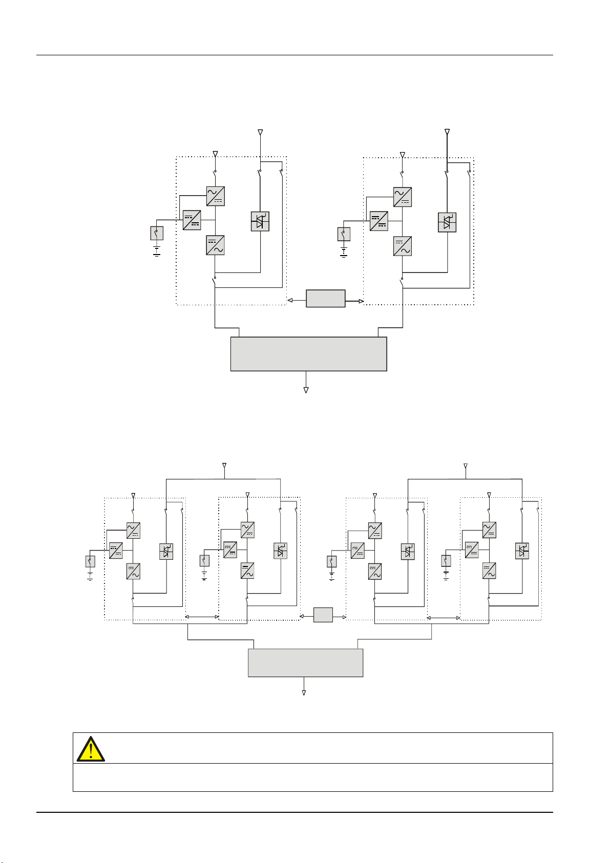
76 Chapter 7 Parallel System And LBS System
Rectifier Rectifier
BypassBypass
Q1
Q2 Q3Q1
Q2 Q3
Q5
Q5
LBS
STS
TO load
To
RectifierRectifier
Bypass
Bypass
Q1
Q2
Q3
Q1
Q2 Q3
Q5
Q5
TO load
Rectifier Rectifier
UPS 1 UPS 4
Q1 Q2 Q3
Q3
Q2
Q1
Q5 Q5
LBS
STS
Parallel
cable
Parallel
cable
UPS 1 UPS 4
To
......
......
Rectifier
Rectifier
Note
In a dual-bus system, the two UPS systems must have the same power rating, voltage and frequency, and the load
Place the UPS modules side by side and interconnect the UPS modules according to the following
instructions.
Figure 7-4 LBS system (UPS module)
Figure 7-5 LBS system (parallel system)
must not exceed the power rating of a UPS module system.
Liebert NXC 60kVA UPS User Manual
Page 92
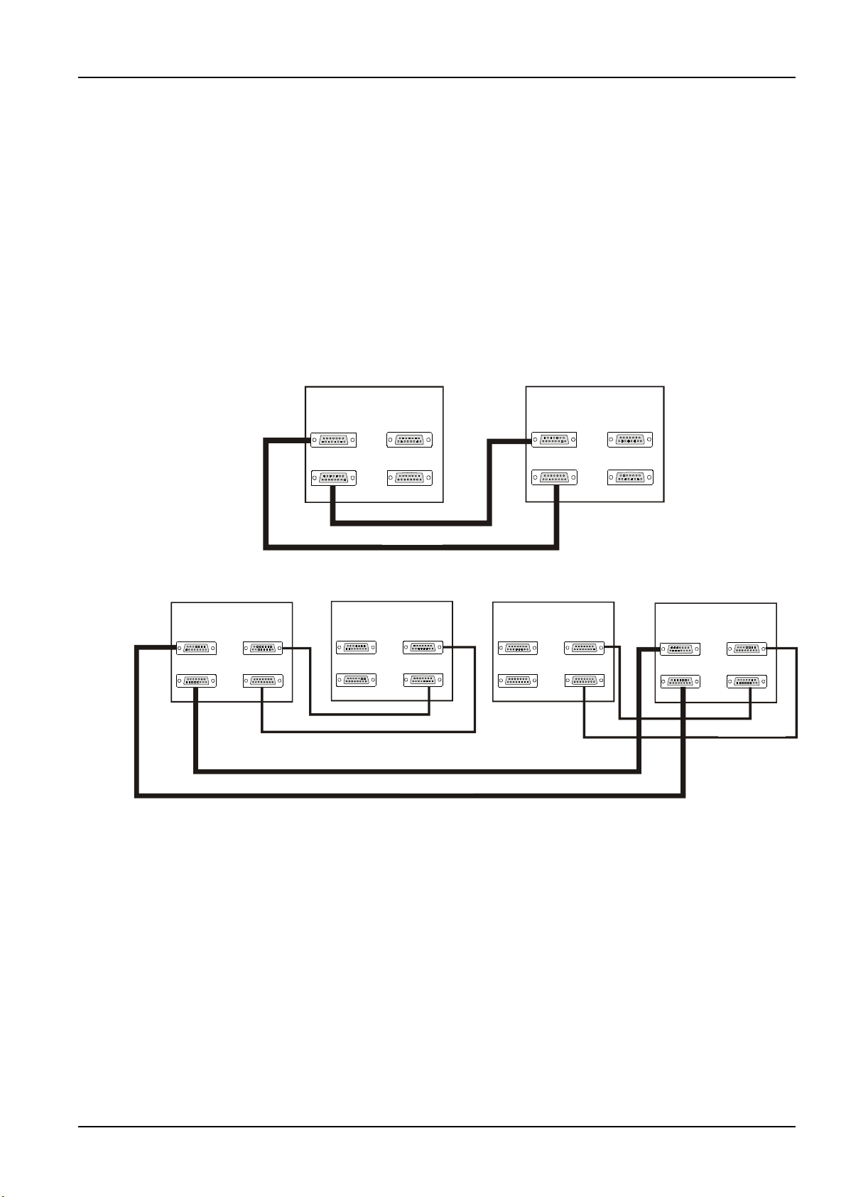
7.4.2 External Protective Device
UPS 1
UPS 2
LBS 1
PARA 1
LB S 2
PARA 2
LBS 1
LBS 2
PARA 1
PARA 2
LBS cable
UPS 1 UPS 2
LBS 1
LBS 2
PARA 1
PARA 1
PARA 2 PARA 2
LBS 1
LBS 2
LBS cable
UPS 1
UPS 2
UPS 3
UPS 4
LBS cable
Parallel cable
LBS 1
PA R A 1
LBS 2 PARA 2
LBS 1
LBS 2
PA R A 1
PA R A 2
LBS 1
LBS 2
PA R A 1
PA R A 2
LBS 1
LBS 2
PA R A 1
PA R A 2
Parallel cable
UPS 1
UPS 2
UPS 3
UPS 4
LBS 1
LBS 1
LBS 1
LBS 1
LBS 2 LBS 2 LBS 2
LBS 2
PARA 1PARA 1
PARA 1 PARA 1
PARA 2
PARA 2PARA 2PARA 2
Parallel cable
LBS cable
Parallel cable
Refer to 3.1.9 External Protective Device.
7.4.3 Power Cable
The power cable of dual-bus power system is similar to that of single system. Refer to 3.1 Wiring Of
Power Cable
.
7.4.4 LBS Cable
The shielded and double-insulated parallel cables are available in lengths 5m, 10m and 15m. Connect the
two optional LBS cables in a ring configuration: from the LBS1 port of one UPS module to LBS2 port of
another UPS module, and from the LBS2 port of one UPS module to LBS1 port of another UPS module, as
shown in Figure 7-6 and Figure 7-7.
Chapter 7 Parallel System And LBS System 77
Figure 7-6 Connection of typical LBS system (UPS module)
Figure 7-7 Connection of typical LBS system (parallel system)
Liebert NXC 60kVA UPS User Manual
Page 93

78 Chapter 8 Options
No.
Option name
Remark
Model
Bypass load sharing
023500CL (before delivery),
023500CN (before
Battery temperature
4
Seismic anchor kit
60kVA
02355403
5
IS-UNITY-DP card
Intellislot ports 1 ~ 3 (Intellislot port 2 recommended)
03020728
6
IS-WEBL card
Intellislot ports 1 ~ 3 (Intellislot port 2 recommended)
02357866
Intellislot ports 1 and 3 (Intellislot port 1
Intellislot ports 1 and 3 (Intellislot port 3
Used to connect and control the external battery
04110499, 04110494,
04110496, 04110497,
C2 electromagnetic
13
Output transformer
Assembled before delivery
023500CM
14
Lightning proof box
Assembled before delivery
023500CQ
This chapter provides the UPS option list, and introduces the functions, installation and configuration of
each option.
8.1 Option List
See Table 8-1 for option list of the UPS.
Chapter 8 Options
Table 8-1 Option list
1
inductor kit
2 40-block battery kit
compensation kit
3
(Standard for EMEA
only)
7 IS-Relay card
8 IS-485L card
9 BCB box
10 Parallel cable Available in 5m, 10m, and 15m
60kVA
Select the battery cable and battery tray, battery
string is user-prepared
Used together with UF-RS485 card 02357078
recommended)
recommended)
string
023500CR (after delivery)
delivery/battery included),
023500CP (before
delivery/battery excluded),
023500CT(before
delivery/battery excluded)
02351105
03028904
02350226
04110495
11 LBS cable Available in 5m, 10m, and 15m
12
shielding assembly
Assembled before delivery 023500CS
8.2 Option Introduction
8.2.1 Bypass Load Sharing Inductor Kit
Install the bypass load sharing inductors for the parallel system comprised of two or more UPS modules,
to ensure the bypass output load sharing for the parallel system. The bypass load sharing inductor is used
to compensate the impedance differentia between SCR and cable. See Table 8-2 for the specifications.
04110498
Liebert NXC 60kVA UPS User Manual
Page 94
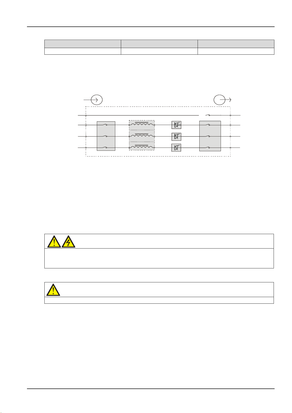
Chapter 8 Options 79
UP S (kVA )
Dimensions (H × W × D) (mm)
Inductor value (uH)
60
170 × 108 × 169
65
N
bA
bB
bC
Q2
Q5
UPS1
oN
oA
oB
oC
Q6
Input
Output
Bypass load sharing inductor
Static switch
Warning
1. Only authorized personnel shall install and replace the inductors.
Note
This procedure will cause the load power-off.
Table 8-2 Specifications of bypass load sharing inductor
Each UPS cabinet has three bypass load sharing inductors, with no extra clearance occupied. The load
sharing rate is generally 10% of the system rated current with the difference of external cable
configuration. Try to make the cable length be the same from bypass to each UPS and from UPS module
output to parallel system connection point.
Figure 8-1 Operation principle of bypass load sharing inductor
Preparation
1. Prepare the installation tools, including a cross head screwdriver, a pair of diagonal cutting pliers, a
sleeve and an adjustable spanner.
2. Check that all installation materials are present and complete, including three bypass load sharing
inductors, four M5 × 12 sems screws (for fixing the inductors), six M6 × 16 sems screws (for fixing the
power cables), six M6 flat washers and nuts.
Procedures
2. Connect the cables strictly following the instructions. Failure to observe this may cause damage to the UPS and
the inductors.
1. Shut down the UPS completely.
a) Close the load.
b) Refer to 5.6.1 Procedures For Completely Powering Down UPS for UPS module shutdown, and 7.3.5
Procedures For Completely Powering Down UPS for parallel system shutdown.
c) All the LCDS are off, wait five minutes for the internal DC bus capacitors of the UPS complete
discharging.
2. Open the cabinet front door and battery comparment, and remove the side panels of the UPS cabinet,
then reserve the removed screws.
3. Install the three bypass load sharing inductors, see Figure 8-2.
Liebert NXC 60kVA UPS User Manual
Page 95
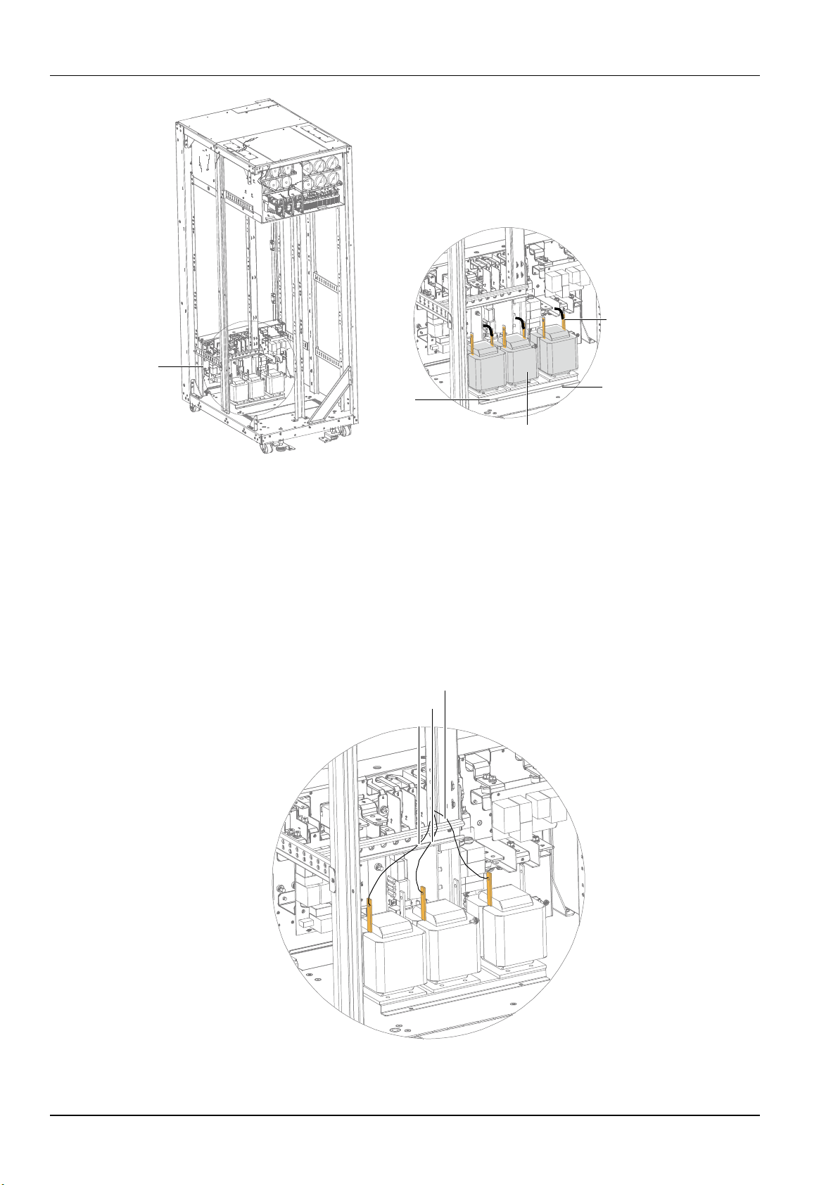
80 Chapter 8 Options
A
Baseplate
Inductors A/B/C
Sems screw
A Amplified view
Cable connection teminal
Baseplate
Inductors A/B/C
Sems screw
Cable connection terminal
A
W01
W02
W03
Figure 8-2 Position of bypass load sharing inductors
Place the three inductors in the installation positions shown in Figure 8-2, and fix them on the base plate
of the UPS cabinet with M5 × 12 sems screws (4 pcs) through the four installation holes.
4. Connection of bypass load sharing inductors.
a) Remove the fixing screws on three cables W01, W02 and W03.
b) Refer to Figure 8-3, respectively connect one end of W01 ~ W03 to inductor A, inductor B, and inductor
C. Use the M6 × 16 sems screws, M6 flat washers and nuts to fasten the terminals. The torque value is
4.8N.m.
Figure 8-3 Connection of inductor (1)
Liebert NXC 60kVA UPS User Manual
Page 96
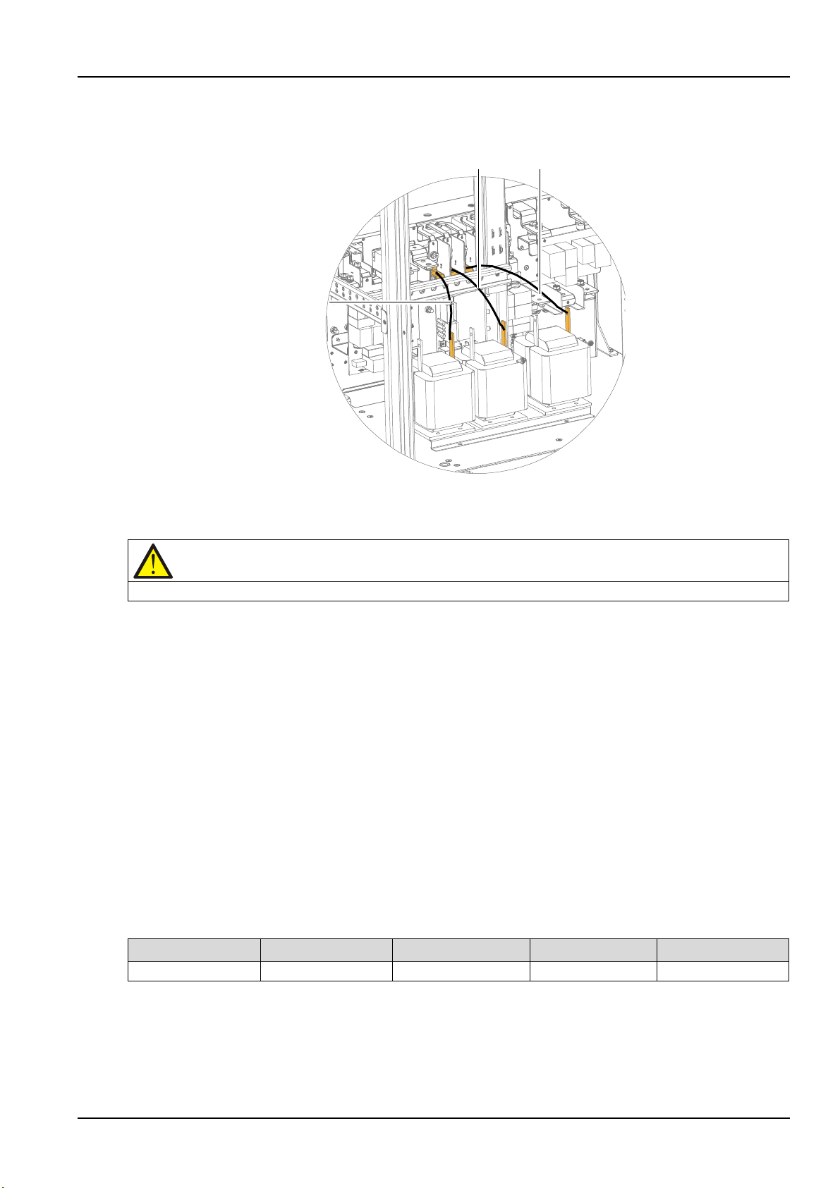
Chapter 8 Options 81
W31
W32
W33
W31
W32
W33
Note
Ensure that there are no foreign matters inside the UPS cabinet before closing the door.
Dimensions
Overall height (H)
Container height (h)
Length (L)
Width (W)
mm (inch)
178.3±2 (7.02±0.08)
154.8±2 (6.09±0.08)
195.6±2 (7.7±0.08)
130±1.5 (5.12±0.06)
c) Respectively connect the other end of W31 ~ W33 to terminals on top of bypass Input switch Q2, and
use the M6 × 16 sems screws to fasten the terminals. The torque value is 4.8N.m. See Figure 8-4.
Figure 8-4 Connection of inductor (2)
5. Replace the left side panel and close the front door of the UPS.
Now, the installation and connection of the bypass load sharing inductors are complete.
Maintenance
1. Keep the connections tight. Tighten all connections in installation, and periodically check them.
2. Keep the inductors clean. Maintain the inductors free of dust and moisture.
3. Keep good records. Inform the service engineer for on-site maintenance in time.
8.2.2 Internal Battery Kit
Vertiv provides two kind of internal battery kits for the user when UPS internal battery or corresponding
kits is required. Kit: 40-block internal battery kit (factory installation), or select the battery cable, battery
tray, screws, cable tie, protective cap and battery fuse (site installation).
Note: For 40-block internal battery kit (factory installation), Vertiv provides valve-regulated lead acid
battery -GP 12340-12V-34.0Ah, see Table 8-3 for its parameters.
Table 8-3 Parameters of valve-regulated lead acid battery -GP 12340-12V-34.0Ah
Liebert NXC 60kVA UPS User Manual
Page 97
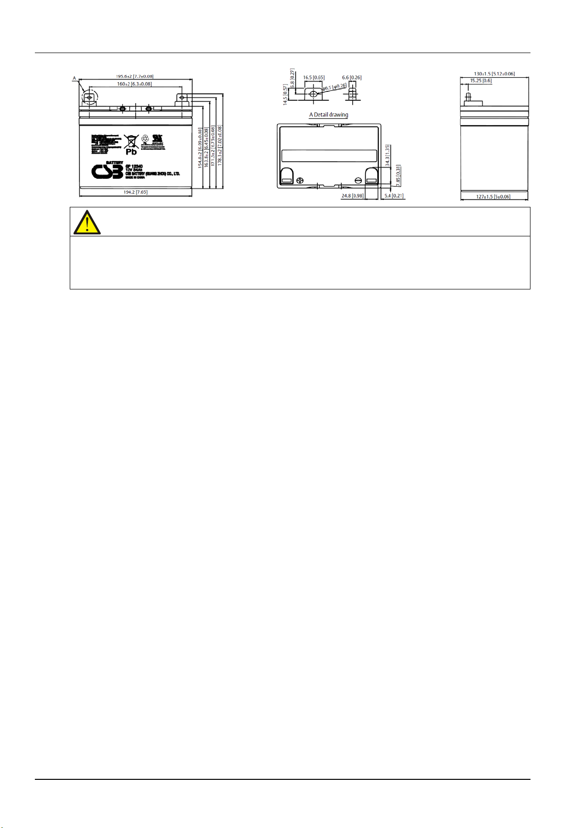
82 Chapter 8 Options
Note
1. There is no battery for 40-block internal battery kit (site installation).
2. Battery cable, battery tray and protective cap are designed according to the specifications of valve-regulated lead
acid battery -GP 12340-12V-34.0Ah. If the customer needs 40-block internal battery kit for site installation, please
purchase battery of the same specification.
Preparation
1. Prepare the installation tools, including a cross head screwdriver, a pair of insulated gloves, a sleeve, an
adjustable spanner, and a multimeter.
2. Check that all installation materials are present and complete, including internal battery, eight battery
trays and corresponding battery power cables.
Procedures
1. Shut down the UPS completely.
a) Close the load.
b) Refer to 5.6.1 Procedures For Completely Powering Down UPS for UPS module shutdown, and 7.3.5
Procedures For Completely Powering Down UPS for parallel system shutdown.
c) All the LCDS are off, wait five minutes for the internal DC bus capacitors of the UPS complete
discharging.
2. Install the internal battery fuse and the battery cables.
Open the cabinet front door, remove the baffle of switches, side panel and rear panel, and then install the
cables (W19, W20 and W21) shown in Figure 8-5. Note to fix W20 and original W14 together.
Liebert NXC 60kVA UPS User Manual
Page 98
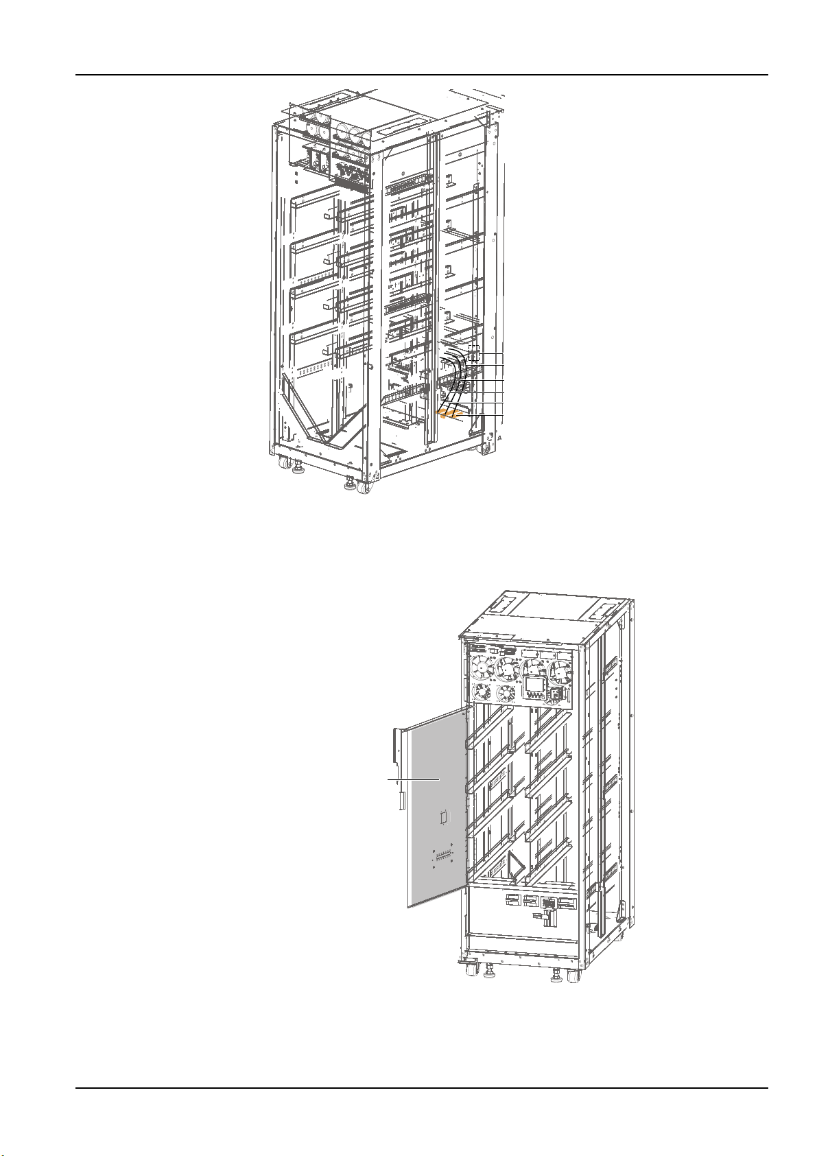
Chapter 8 Options 83
W21(+)
W20 (N)
W19 (-)
Hex sems screw M6*16
Torque value: 4.8N.m
Holes for cables binding
Holes for cables binding
Battery compartment door
Figure 8-5 Installing internal battery fuse and battery cables (front view)
3. Open the cabinet front door, remove the screws to open the battery compartment door (see Figure 8-6),
and reserve the removed screws.
Figure 8-6 Opening battery compartment door
Liebert NXC 60kVA UPS User Manual
Page 99
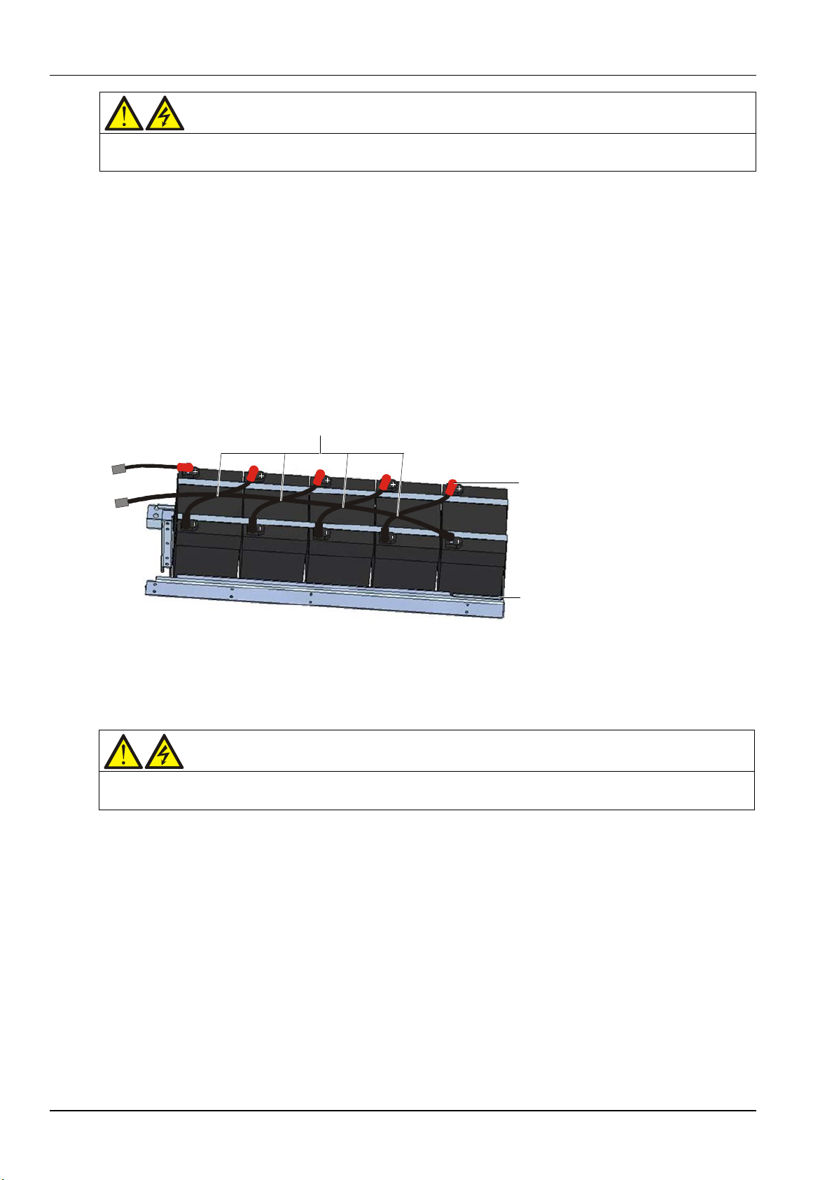
84 Chapter 8 Options
Warning
The following operations of battery and battery tray shall be operated by authorized service engineer with insulated
Bind cables here
Hex sems screw M6*20, spring washer
/plain washer, torque value: 4.8N.m
Position of battery plastic enclosure
Warning
The battery tray shall be installed from the bottom layer upwards, to avoid falling over caused by high center of
gloves worn.
4. After placing the battery plastic enclosure in the battery tray, you can place the battery into
corresponding position in battery tray one by one according to internal battery connection shown in
Figure 6-1, and then use M6*20 sems screws/spring washers/flat washers and battery cables to fix the
battery terminals, torque value is 4.8N.m. Note that the protective caps should be added onto the battery
terminals (red for +, black for -).
Use straps to place all the batteries into battery trays. Note that the straps must pass across the waist
type holes at both sides of the battery tray, and each battery tray needs four straps. Then lead the
connection terminals between battery trays. As shown in Figure 8-7.
Use the multimeter to measure voltages (50Vdc~70Vdc) between connection terminals, so as to
verify that the cable connection is correct.
Figure 8-7 Placing the battery into battery tray
5. According to Figure 8-8, insert the trays with batteries installed into the battery compartment one by
one, and ensure the No.1 ~ No.8 battery trays correspond to 1 ~ 4 layers (from bottom to top) of the
battery compartment, otherwise the battery voltage may be abnormal.
gravity.
Liebert NXC 60kVA UPS User Manual
Page 100
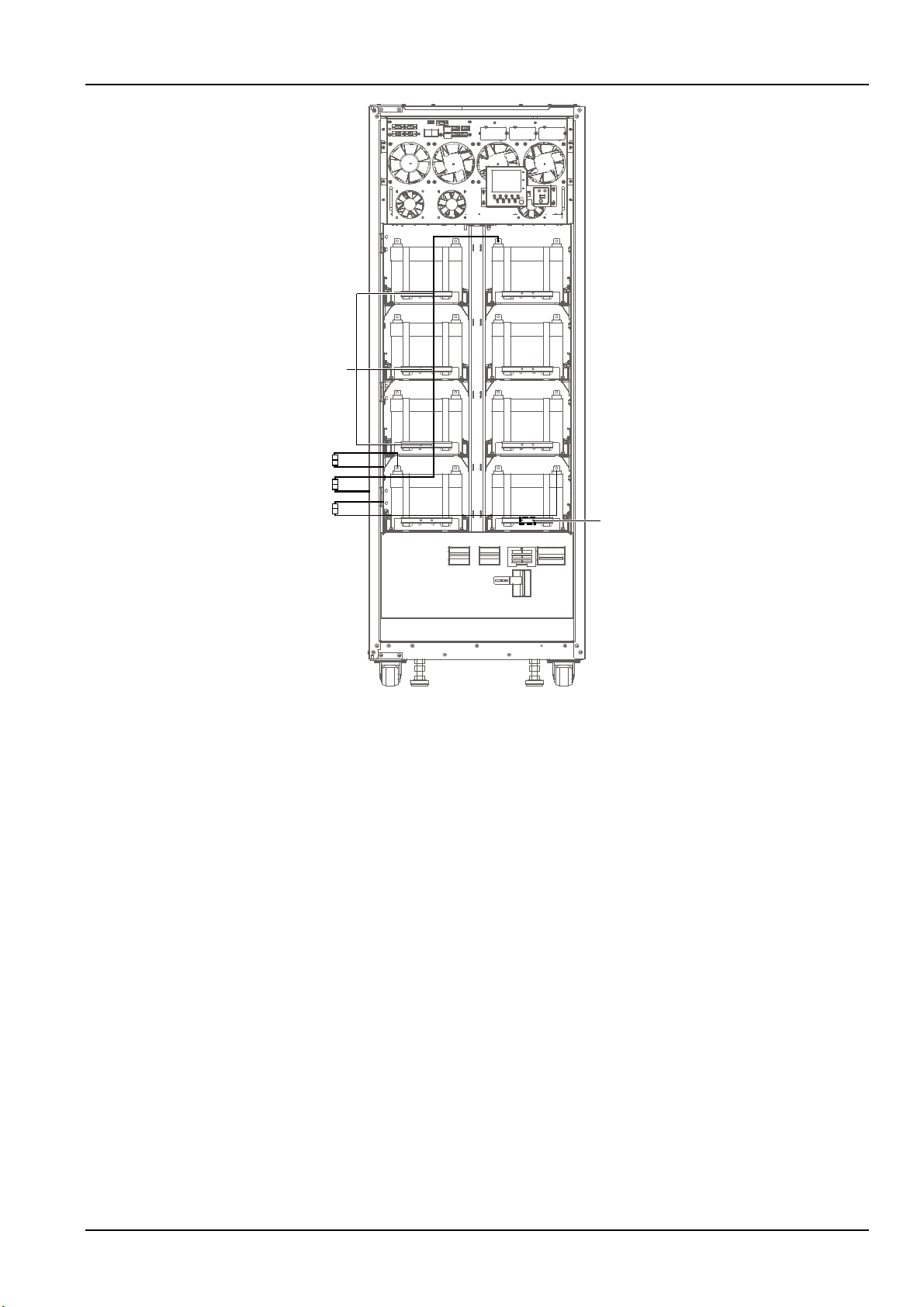
Chapter 8 Options 85
Bat-4
Bat-3
Bat-5
Bat-6
For cable binding
Bat-7
Bat-8
Paste lable'Bat-8'here, and
Red
Blue
Black
W11
W21
W10
W20
W08
W19
Bat-2
Bat-1
by this analogy for others
Figure 8-8 Connection between battery trays and batteries
6. Use torque value in Figure 8-9 to fix both sides of the battery tray, then pull up the limiting baffle plate.
Liebert NXC 60kVA UPS User Manual
 Loading...