

Vertiv Liebert NX Operation And Maintenance Manual

Liebert® NX™ UPS
Operation and Maintenance Manual — 225-600kVA, Three-Phase, Single-Module &
Multi-Module

CONTACTING VERTIV FOR SUPPORT
To contact Vertiv Liebert® Services for information or repair service in the United States, call 800-543-2378.
Liebert Services offers a complete range of star-up services, repair services, preventive maintenance plans and
service contracts.
For repair or maintenance service outside the 48 contiguous United States, contact Liebert Services, if available
in your area. For areas not covered by Liebert Services, the authorized distributor is responsible for providing
qualified, factory-authorized service.
For Liebert Services to assist you promptly, please have the following information available:
Part numbers: _____________________________________________________________________________________________________________________
Serial numbers:____________________________________________________________________________________________________________________
Rating:_____________________________________________________________________________________________________________________________
Date purchased: ___________________________________________________________________________________________________________________
Date installed: _____________________________________________________________________________________________________________________
Location: __________________________________________________________________________________________________________________________
Input voltage/frequency: __________________________________________________________________________________________________________
Output voltage/frequency: ________________________________________________________________________________________________________
DC source reserve time: ___________________________________________________________________________________________________________
Product Warranty Registration
To register for warranty protection, visit the Service and Support section of our Web site at:
www.liebert.com
Click on Product Registration and fill out the form.
©2016 Vertiv Co. All rights reserved throughout the world.
This document may contain confidential and/or proprietary information of Liebert Corporation, and its receipt or possession
does not convey any right to reproduce, disclose its contents, or to manufacture or sell anything that it may describe.
Reproduction, disclosure, or use without specific authorization from Liebert Corporation is strictly prohibited.

TABLE OF CONTENTS
IMPORTANT SAFETY INSTRUCTIONS . . . . . . . . . . . . . . . . . . . . . . . . . . . . . . . . . . . . . . . . . . . . . . . . . . . . . . .1
SAVE THESE INSTRUCTIONS . . . . . . . . . . . . . . . . . . . . . . . . . . . . . . . . . . . . . . . . . . . . . . . . . . . . . . . . 1
1.0 I
NTRODUCTION. . . . . . . . . . . . . . . . . . . . . . . . . . . . . . . . . . . . . . . . . . . . . . . . . . . . . . . . . . . . . . . . . 3
1.1 General Description . . . . . . . . . . . . . . . . . . . . . . . . . . . . . . . . . . . . . . . . . . . . . . . . . . . . . . . . . . . . . . . . . . . . . . . . . . . . . . .3
1.2 Modes of Operation . . . . . . . . . . . . . . . . . . . . . . . . . . . . . . . . . . . . . . . . . . . . . . . . . . . . . . . . . . . . . . . . . . . . . . . . . . . . . . 4
1.2.1 Normal Mode . . . . . . . . . . . . . . . . . . . . . . . . . . . . . . . . . . . . . . . . . . . . . . . . . . . . . . . . . . . . . . . . . . . . . . . . . . . . . . . . . . . . . 4
1.2.2 Eco Mode . . . . . . . . . . . . . . . . . . . . . . . . . . . . . . . . . . . . . . . . . . . . . . . . . . . . . . . . . . . . . . . . . . . . . . . . . . . . . . . . . . . . . . . . 4
1.2.3 Bypass Mode . . . . . . . . . . . . . . . . . . . . . . . . . . . . . . . . . . . . . . . . . . . . . . . . . . . . . . . . . . . . . . . . . . . . . . . . . . . . . . . . . . . . . 4
1.2.4 Battery Mode. . . . . . . . . . . . . . . . . . . . . . . . . . . . . . . . . . . . . . . . . . . . . . . . . . . . . . . . . . . . . . . . . . . . . . . . . . . . . . . . . . . . . 4
1.2.5 Maintenance Bypass . . . . . . . . . . . . . . . . . . . . . . . . . . . . . . . . . . . . . . . . . . . . . . . . . . . . . . . . . . . . . . . . . . . . . . . . . . . . . . 4
1.3 Options. . . . . . . . . . . . . . . . . . . . . . . . . . . . . . . . . . . . . . . . . . . . . . . . . . . . . . . . . . . . . . . . . . . . . . . . . . . . . . . . . . . . . . . . . . .5
2.0 OPERATION. . . . . . . . . . . . . . . . . . . . . . . . . . . . . . . . . . . . . . . . . . . . . . . . . . . . . . . . . . . . . . . . . . . . 6
2.1 Physical Layout of the UPS. . . . . . . . . . . . . . . . . . . . . . . . . . . . . . . . . . . . . . . . . . . . . . . . . . . . . . . . . . . . . . . . . . . . . . . 6
2.2 Interface Display Features. . . . . . . . . . . . . . . . . . . . . . . . . . . . . . . . . . . . . . . . . . . . . . . . . . . . . . . . . . . . . . . . . . . . . . . . .8
2.3 Touchscreen Navigation . . . . . . . . . . . . . . . . . . . . . . . . . . . . . . . . . . . . . . . . . . . . . . . . . . . . . . . . . . . . . . . . . . . . . . . . .10
2.3.1 Main Display Screen . . . . . . . . . . . . . . . . . . . . . . . . . . . . . . . . . . . . . . . . . . . . . . . . . . . . . . . . . . . . . . . . . . . . . . . . . . . . . 10
2.3.2 Status . . . . . . . . . . . . . . . . . . . . . . . . . . . . . . . . . . . . . . . . . . . . . . . . . . . . . . . . . . . . . . . . . . . . . . . . . . . . . . . . . . . . . . . . . . . . 11
2.3.3 Events Log Menu . . . . . . . . . . . . . . . . . . . . . . . . . . . . . . . . . . . . . . . . . . . . . . . . . . . . . . . . . . . . . . . . . . . . . . . . . . . . . . . . .16
2.3.4 Measures Menu. . . . . . . . . . . . . . . . . . . . . . . . . . . . . . . . . . . . . . . . . . . . . . . . . . . . . . . . . . . . . . . . . . . . . . . . . . . . . . . . . . .16
2.3.5 Battery Menu . . . . . . . . . . . . . . . . . . . . . . . . . . . . . . . . . . . . . . . . . . . . . . . . . . . . . . . . . . . . . . . . . . . . . . . . . . . . . . . . . . . . 20
2.3.6 LIFE
2.3.7 Settings Menu . . . . . . . . . . . . . . . . . . . . . . . . . . . . . . . . . . . . . . . . . . . . . . . . . . . . . . . . . . . . . . . . . . . . . . . . . . . . . . . . . . . 23
2.4 Animated One-Line Mimic. . . . . . . . . . . . . . . . . . . . . . . . . . . . . . . . . . . . . . . . . . . . . . . . . . . . . . . . . . . . . . . . . . . . . . . 24
2.4.1 Functional Blocks . . . . . . . . . . . . . . . . . . . . . . . . . . . . . . . . . . . . . . . . . . . . . . . . . . . . . . . . . . . . . . . . . . . . . . . . . . . . . . . . 24
2.4.2 About Menu . . . . . . . . . . . . . . . . . . . . . . . . . . . . . . . . . . . . . . . . . . . . . . . . . . . . . . . . . . . . . . . . . . . . . . . . . . . . . . . . . . . . . 24
2.5 Modes of Operation . . . . . . . . . . . . . . . . . . . . . . . . . . . . . . . . . . . . . . . . . . . . . . . . . . . . . . . . . . . . . . . . . . . . . . . . . . . . . 25
2.5.1 Load on Bypass. . . . . . . . . . . . . . . . . . . . . . . . . . . . . . . . . . . . . . . . . . . . . . . . . . . . . . . . . . . . . . . . . . . . . . . . . . . . . . . . . . 25
2.5.2 Normal Mode—Load on UPS . . . . . . . . . . . . . . . . . . . . . . . . . . . . . . . . . . . . . . . . . . . . . . . . . . . . . . . . . . . . . . . . . . . . . 27
2.5.3 Input Power Failure—Load on DC Source . . . . . . . . . . . . . . . . . . . . . . . . . . . . . . . . . . . . . . . . . . . . . . . . . . . . . . . . . 27
2.5.4 Off DC Source . . . . . . . . . . . . . . . . . . . . . . . . . . . . . . . . . . . . . . . . . . . . . . . . . . . . . . . . . . . . . . . . . . . . . . . . . . . . . . . . . . . 28
2.5.5 Remote Emergency Power Off . . . . . . . . . . . . . . . . . . . . . . . . . . . . . . . . . . . . . . . . . . . . . . . . . . . . . . . . . . . . . . . . . . . . 28
2.6 Eco Mode Active. . . . . . . . . . . . . . . . . . . . . . . . . . . . . . . . . . . . . . . . . . . . . . . . . . . . . . . . . . . . . . . . . . . . . . . . . . . . . . . . 29
2.6.1 Eco Mode Activation and Control . . . . . . . . . . . . . . . . . . . . . . . . . . . . . . . . . . . . . . . . . . . . . . . . . . . . . . . . . . . . . . . . . 29
2.6.2 Active Eco Mode. . . . . . . . . . . . . . . . . . . . . . . . . . . . . . . . . . . . . . . . . . . . . . . . . . . . . . . . . . . . . . . . . . . . . . . . . . . . . . . . . 29
2.6.3 Normal—Active Eco Mode . . . . . . . . . . . . . . . . . . . . . . . . . . . . . . . . . . . . . . . . . . . . . . . . . . . . . . . . . . . . . . . . . . . . . . . 29
2.6.4 Inverter Stop—Active Eco Mode. . . . . . . . . . . . . . . . . . . . . . . . . . . . . . . . . . . . . . . . . . . . . . . . . . . . . . . . . . . . . . . . . . 30
2.6.5 Overload—Active Eco Mode. . . . . . . . . . . . . . . . . . . . . . . . . . . . . . . . . . . . . . . . . . . . . . . . . . . . . . . . . . . . . . . . . . . . . . 30
2.6.6 Emergency—Due to Source Supply Failure or Variance Beyond Tolerance Limits, Active Eco
2.6.7 Return to Normal Conditions-Active Eco Mode. . . . . . . . . . . . . . . . . . . . . . . . . . . . . . . . . . . . . . . . . . . . . . . . . . . . 30
™
Menu. . . . . . . . . . . . . . . . . . . . . . . . . . . . . . . . . . . . . . . . . . . . . . . . . . . . . . . . . . . . . . . . . . . . . . . . . . . . . . . . . . . . . . 22
Mode. . . . . . . . . . . . . . . . . . . . . . . . . . . . . . . . . . . . . . . . . . . . . . . . . . . . . . . . . . . . . . . . . . . . . . . . . . . . . . . . . . . . . . . . . . . . 30
i

2.7 Manual Operations—All Systems . . . . . . . . . . . . . . . . . . . . . . . . . . . . . . . . . . . . . . . . . . . . . . . . . . . . . . . . . . . . . . . . 30
2.7.1 Startup—Single Module System . . . . . . . . . . . . . . . . . . . . . . . . . . . . . . . . . . . . . . . . . . . . . . . . . . . . . . . . . . . . . . . . . . 34
2.7.2 Startup Single Module System from Maintenance Bypass . . . . . . . . . . . . . . . . . . . . . . . . . . . . . . . . . . . . . . . . . 35
2.7.3 Load Transfer and Retransfer—Single Module System. . . . . . . . . . . . . . . . . . . . . . . . . . . . . . . . . . . . . . . . . . . . . 37
2.7.4 Maintenance Bypass Load Transfers—Single Module System. . . . . . . . . . . . . . . . . . . . . . . . . . . . . . . . . . . . . . 37
2.7.5 Shut Down Single Module UPS System . . . . . . . . . . . . . . . . . . . . . . . . . . . . . . . . . . . . . . . . . . . . . . . . . . . . . . . . . . . 38
2.7.6 Startup—1+N Multi-Module System with Maintenance Bypass Cabinet . . . . . . . . . . . . . . . . . . . . . . . . . . . . 39
2.7.7 Transfer the Load from UPS to Bypass: 1+N System . . . . . . . . . . . . . . . . . . . . . . . . . . . . . . . . . . . . . . . . . . . . . . . 40
2.7.8 Transfer Load from Bypass to UPS: 1+N Distributed Bypass System . . . . . . . . . . . . . . . . . . . . . . . . . . . . . . . 40
2.7.9 Load Transfer-1+N System—Remove One UPS Module from System (Collective). . . . . . . . . . . . . . . . . . . .41
2.7.10 Load Transfer-1+N System—Add One UPS Module to the System (Collective). . . . . . . . . . . . . . . . . . . . . . .41
2.7.11 De-Energize 1+N System With Maintenance Bypass Cabinet. . . . . . . . . . . . . . . . . . . . . . . . . . . . . . . . . . . . . . . .41
2.8 Automatic Operations. . . . . . . . . . . . . . . . . . . . . . . . . . . . . . . . . . . . . . . . . . . . . . . . . . . . . . . . . . . . . . . . . . . . . . . . . . . 42
2.8.1 Overloads (Without Transfer) . . . . . . . . . . . . . . . . . . . . . . . . . . . . . . . . . . . . . . . . . . . . . . . . . . . . . . . . . . . . . . . . . . . . 42
2.8.2 Automatic Transfers to Bypass (Overload Condition). . . . . . . . . . . . . . . . . . . . . . . . . . . . . . . . . . . . . . . . . . . . . . 43
2.8.3 Automatic Transfers to Bypass, UPS System Faults . . . . . . . . . . . . . . . . . . . . . . . . . . . . . . . . . . . . . . . . . . . . . . . 43
2.8.4 Automatic Retransfers to UPS. . . . . . . . . . . . . . . . . . . . . . . . . . . . . . . . . . . . . . . . . . . . . . . . . . . . . . . . . . . . . . . . . . . . 44
3.0 UPS MESSAGES: STATUS, WARNING, FAULT . . . . . . . . . . . . . . . . . . . . . . . . . . . . . . . . . . . . . . . . 45
4.0 C
ONNECTIVITY . . . . . . . . . . . . . . . . . . . . . . . . . . . . . . . . . . . . . . . . . . . . . . . . . . . . . . . . . . . . . . . . 54
4.1 Network and BMS Connectivity and Monitoring . . . . . . . . . . . . . . . . . . . . . . . . . . . . . . . . . . . . . . . . . . . . . . . . . . 54
4.1.1 Determining the type of Card in Your System . . . . . . . . . . . . . . . . . . . . . . . . . . . . . . . . . . . . . . . . . . . . . . . . . . . . . 54
4.2 Connection Points . . . . . . . . . . . . . . . . . . . . . . . . . . . . . . . . . . . . . . . . . . . . . . . . . . . . . . . . . . . . . . . . . . . . . . . . . . . . . . 54
4.2.1 Available Selectable Input Contacts . . . . . . . . . . . . . . . . . . . . . . . . . . . . . . . . . . . . . . . . . . . . . . . . . . . . . . . . . . . . . . 55
4.2.2 Available Selectable Output Contacts . . . . . . . . . . . . . . . . . . . . . . . . . . . . . . . . . . . . . . . . . . . . . . . . . . . . . . . . . . . . 56
5.0 MAINTENANCE . . . . . . . . . . . . . . . . . . . . . . . . . . . . . . . . . . . . . . . . . . . . . . . . . . . . . . . . . . . . . . . . 57
5.1 Safety Precautions . . . . . . . . . . . . . . . . . . . . . . . . . . . . . . . . . . . . . . . . . . . . . . . . . . . . . . . . . . . . . . . . . . . . . . . . . . . . . . 57
5.2 Vertiv Liebert Services . . . . . . . . . . . . . . . . . . . . . . . . . . . . . . . . . . . . . . . . . . . . . . . . . . . . . . . . . . . . . . . . . . . . . . . . . . 57
5.3 Routine Maintenance . . . . . . . . . . . . . . . . . . . . . . . . . . . . . . . . . . . . . . . . . . . . . . . . . . . . . . . . . . . . . . . . . . . . . . . . . . . 58
5.3.1 Record Log . . . . . . . . . . . . . . . . . . . . . . . . . . . . . . . . . . . . . . . . . . . . . . . . . . . . . . . . . . . . . . . . . . . . . . . . . . . . . . . . . . . . . . 58
5.3.2 Air Filters. . . . . . . . . . . . . . . . . . . . . . . . . . . . . . . . . . . . . . . . . . . . . . . . . . . . . . . . . . . . . . . . . . . . . . . . . . . . . . . . . . . . . . . . 58
5.3.3 Limited Life Components . . . . . . . . . . . . . . . . . . . . . . . . . . . . . . . . . . . . . . . . . . . . . . . . . . . . . . . . . . . . . . . . . . . . . . . . 59
5.4 Battery Maintenance . . . . . . . . . . . . . . . . . . . . . . . . . . . . . . . . . . . . . . . . . . . . . . . . . . . . . . . . . . . . . . . . . . . . . . . . . . . . 60
5.4.1 Battery Safety Precautions . . . . . . . . . . . . . . . . . . . . . . . . . . . . . . . . . . . . . . . . . . . . . . . . . . . . . . . . . . . . . . . . . . . . . . . 60
5.5 Detecting Trouble. . . . . . . . . . . . . . . . . . . . . . . . . . . . . . . . . . . . . . . . . . . . . . . . . . . . . . . . . . . . . . . . . . . . . . . . . . . . . . . 63
5.5.1 Items to check include: . . . . . . . . . . . . . . . . . . . . . . . . . . . . . . . . . . . . . . . . . . . . . . . . . . . . . . . . . . . . . . . . . . . . . . . . . . . 63
5.6 Reporting a Problem . . . . . . . . . . . . . . . . . . . . . . . . . . . . . . . . . . . . . . . . . . . . . . . . . . . . . . . . . . . . . . . . . . . . . . . . . . . . 63
5.7 Upstream Feeder Circuit Breaker Setting Inspections . . . . . . . . . . . . . . . . . . . . . . . . . . . . . . . . . . . . . . . . . . . . 63
5.8 AC Output Ground Fault Detection . . . . . . . . . . . . . . . . . . . . . . . . . . . . . . . . . . . . . . . . . . . . . . . . . . . . . . . . . . . . . . 64
6.0 SPECIFICATIONS . . . . . . . . . . . . . . . . . . . . . . . . . . . . . . . . . . . . . . . . . . . . . . . . . . . . . . . . . . . . . . . 65
6.1 DC Sources . . . . . . . . . . . . . . . . . . . . . . . . . . . . . . . . . . . . . . . . . . . . . . . . . . . . . . . . . . . . . . . . . . . . . . . . . . . . . . . . . . . . . 65
6.1.1 Battery Operation. . . . . . . . . . . . . . . . . . . . . . . . . . . . . . . . . . . . . . . . . . . . . . . . . . . . . . . . . . . . . . . . . . . . . . . . . . . . . . . . 65
6.2 Other DC Sources. . . . . . . . . . . . . . . . . . . . . . . . . . . . . . . . . . . . . . . . . . . . . . . . . . . . . . . . . . . . . . . . . . . . . . . . . . . . . . . 65
6.3 Battery DC Ground Fault Detection . . . . . . . . . . . . . . . . . . . . . . . . . . . . . . . . . . . . . . . . . . . . . . . . . . . . . . . . . . . . . . 65
6.4 Environmental Conditions . . . . . . . . . . . . . . . . . . . . . . . . . . . . . . . . . . . . . . . . . . . . . . . . . . . . . . . . . . . . . . . . . . . . . . . 66
ii

6.5 Thermal Runaway Protection. . . . . . . . . . . . . . . . . . . . . . . . . . . . . . . . . . . . . . . . . . . . . . . . . . . . . . . . . . . . . . . . . . . . 66
APPENDIX A-SYSTEM CONFIGURATION . . . . . . . . . . . . . . . . . . . . . . . . . . . . . . . . . . . . . . . . . . . . . . . .A68
FIGURES
Figure 1 Typical single module UPS system one-line diagram. . . . . . . . . . . . . . . . . . . . . . . . . . . . . . . . . . . . . . . . . . . .3
Figure 2 Main component locations—225-300kVA Liebert NX. . . . . . . . . . . . . . . . . . . . . . . . . . . . . . . . . . . . . . . . . . 6
Figure 3 Main component details—225 to 300kVA Liebert NX. . . . . . . . . . . . . . . . . . . . . . . . . . . . . . . . . . . . . . . . . . .7
Figure 4 Main component details, 400-600kVA Liebert NX . . . . . . . . . . . . . . . . . . . . . . . . . . . . . . . . . . . . . . . . . . . . .8
Figure 5 Main display screen, typical . . . . . . . . . . . . . . . . . . . . . . . . . . . . . . . . . . . . . . . . . . . . . . . . . . . . . . . . . . . . . . . . . . 9
Figure 6 Normal Mode . . . . . . . . . . . . . . . . . . . . . . . . . . . . . . . . . . . . . . . . . . . . . . . . . . . . . . . . . . . . . . . . . . . . . . . . . . . . . . . . 9
Figure 7 Utility fail . . . . . . . . . . . . . . . . . . . . . . . . . . . . . . . . . . . . . . . . . . . . . . . . . . . . . . . . . . . . . . . . . . . . . . . . . . . . . . . . . . . .10
Figure 8 Load on bypass . . . . . . . . . . . . . . . . . . . . . . . . . . . . . . . . . . . . . . . . . . . . . . . . . . . . . . . . . . . . . . . . . . . . . . . . . . . . . .10
Figure 9 Main display screen, MBD open. . . . . . . . . . . . . . . . . . . . . . . . . . . . . . . . . . . . . . . . . . . . . . . . . . . . . . . . . . . . . . . 12
Figure 10 Load status . . . . . . . . . . . . . . . . . . . . . . . . . . . . . . . . . . . . . . . . . . . . . . . . . . . . . . . . . . . . . . . . . . . . . . . . . . . . . . . . . .12
Figure 11 Rectifier status. . . . . . . . . . . . . . . . . . . . . . . . . . . . . . . . . . . . . . . . . . . . . . . . . . . . . . . . . . . . . . . . . . . . . . . . . . . . . . . 13
Figure 12 Bypass status . . . . . . . . . . . . . . . . . . . . . . . . . . . . . . . . . . . . . . . . . . . . . . . . . . . . . . . . . . . . . . . . . . . . . . . . . . . . . . . . 13
Figure 13 Inverter status . . . . . . . . . . . . . . . . . . . . . . . . . . . . . . . . . . . . . . . . . . . . . . . . . . . . . . . . . . . . . . . . . . . . . . . . . . . . . . .14
Figure 14 Charger/Booster status. . . . . . . . . . . . . . . . . . . . . . . . . . . . . . . . . . . . . . . . . . . . . . . . . . . . . . . . . . . . . . . . . . . . . . .14
Figure 15 Battery status. . . . . . . . . . . . . . . . . . . . . . . . . . . . . . . . . . . . . . . . . . . . . . . . . . . . . . . . . . . . . . . . . . . . . . . . . . . . . . . .15
Figure 16 Status summary. . . . . . . . . . . . . . . . . . . . . . . . . . . . . . . . . . . . . . . . . . . . . . . . . . . . . . . . . . . . . . . . . . . . . . . . . . . . . .16
Figure 17 Rectifier measures . . . . . . . . . . . . . . . . . . . . . . . . . . . . . . . . . . . . . . . . . . . . . . . . . . . . . . . . . . . . . . . . . . . . . . . . . . . 17
Figure 18 Bypass measures . . . . . . . . . . . . . . . . . . . . . . . . . . . . . . . . . . . . . . . . . . . . . . . . . . . . . . . . . . . . . . . . . . . . . . . . . . . .17
Figure 19 Inverter measures . . . . . . . . . . . . . . . . . . . . . . . . . . . . . . . . . . . . . . . . . . . . . . . . . . . . . . . . . . . . . . . . . . . . . . . . . . . .18
Figure 20 Charger/Booster measures . . . . . . . . . . . . . . . . . . . . . . . . . . . . . . . . . . . . . . . . . . . . . . . . . . . . . . . . . . . . . . . . . . .18
Figure 21 Battery measures . . . . . . . . . . . . . . . . . . . . . . . . . . . . . . . . . . . . . . . . . . . . . . . . . . . . . . . . . . . . . . . . . . . . . . . . . . . .19
Figure 22 Load measures. . . . . . . . . . . . . . . . . . . . . . . . . . . . . . . . . . . . . . . . . . . . . . . . . . . . . . . . . . . . . . . . . . . . . . . . . . . . . . .19
Figure 23 Battery parameters. . . . . . . . . . . . . . . . . . . . . . . . . . . . . . . . . . . . . . . . . . . . . . . . . . . . . . . . . . . . . . . . . . . . . . . . . . .21
Figure 24 LIFE menu . . . . . . . . . . . . . . . . . . . . . . . . . . . . . . . . . . . . . . . . . . . . . . . . . . . . . . . . . . . . . . . . . . . . . . . . . . . . . . . . . . 22
Figure 25 Settings Menus . . . . . . . . . . . . . . . . . . . . . . . . . . . . . . . . . . . . . . . . . . . . . . . . . . . . . . . . . . . . . . . . . . . . . . . . . . . . . 23
Figure 26 About menu . . . . . . . . . . . . . . . . . . . . . . . . . . . . . . . . . . . . . . . . . . . . . . . . . . . . . . . . . . . . . . . . . . . . . . . . . . . . . . . . 24
Figure 27 Load on bypass, UPS not operating . . . . . . . . . . . . . . . . . . . . . . . . . . . . . . . . . . . . . . . . . . . . . . . . . . . . . . . . . . 25
Figure 28 Load on bypass, UPS available. . . . . . . . . . . . . . . . . . . . . . . . . . . . . . . . . . . . . . . . . . . . . . . . . . . . . . . . . . . . . . . 26
Figure 29 Eco Mode one-line mimic display . . . . . . . . . . . . . . . . . . . . . . . . . . . . . . . . . . . . . . . . . . . . . . . . . . . . . . . . . . . . 26
Figure 30 Load on UPS, bypass available. . . . . . . . . . . . . . . . . . . . . . . . . . . . . . . . . . . . . . . . . . . . . . . . . . . . . . . . . . . . . . . 27
Figure 31 Input power failure, load on DC source . . . . . . . . . . . . . . . . . . . . . . . . . . . . . . . . . . . . . . . . . . . . . . . . . . . . . . . 27
Figure 32 Load on UPS, DC source not available. . . . . . . . . . . . . . . . . . . . . . . . . . . . . . . . . . . . . . . . . . . . . . . . . . . . . . . . 28
Figure 33 Remote Emergency Power Off . . . . . . . . . . . . . . . . . . . . . . . . . . . . . . . . . . . . . . . . . . . . . . . . . . . . . . . . . . . . . . . 28
Figure 34 Maintenance bypass configurations—Two breaker . . . . . . . . . . . . . . . . . . . . . . . . . . . . . . . . . . . . . . . . . . . .31
Figure 35 Maintenance bypass configurations—Three breaker for single-input UPS . . . . . . . . . . . . . . . . . . . . . . 31
Figure 36 Maintenance bypass configurations—Three breaker for dual-input UPS . . . . . . . . . . . . . . . . . . . . . . . . 31
Figure 37 Maintenance bypass configurations—Four breaker for dual-input UPS . . . . . . . . . . . . . . . . . . . . . . . . 32
Figure 38 Maintenance bypass configurations—Four breaker for dual-input UPS, No CB1 . . . . . . . . . . . . . . . . 32
Figure 39 Maintenance bypass configurations—Distributed bypass, 1+N multi-module . . . . . . . . . . . . . . . . . . 33
Figure 40 Two-module 1+N UPS system, single input, common battery and paralleling switchboard . . . . . . 68
iii

TABLES
Table 1 Measurements for functional blocks . . . . . . . . . . . . . . . . . . . . . . . . . . . . . . . . . . . . . . . . . . . . . . . . . . . . . . . . . .16
Table 2 Functional block information . . . . . . . . . . . . . . . . . . . . . . . . . . . . . . . . . . . . . . . . . . . . . . . . . . . . . . . . . . . . . . . . 24
Table 3 Current-versus-time curves of overload capacity . . . . . . . . . . . . . . . . . . . . . . . . . . . . . . . . . . . . . . . . . . . . . 43
Table 4 UPS status, warning and fault messages . . . . . . . . . . . . . . . . . . . . . . . . . . . . . . . . . . . . . . . . . . . . . . . . . . . . . 45
Table 5 Connectivity combinations . . . . . . . . . . . . . . . . . . . . . . . . . . . . . . . . . . . . . . . . . . . . . . . . . . . . . . . . . . . . . . . . . . 54
Table 6 UPS component service life . . . . . . . . . . . . . . . . . . . . . . . . . . . . . . . . . . . . . . . . . . . . . . . . . . . . . . . . . . . . . . . . . 59
Table 7 Battery voltage, nominal and float . . . . . . . . . . . . . . . . . . . . . . . . . . . . . . . . . . . . . . . . . . . . . . . . . . . . . . . . . . . .61
Table 8 Battery retorque values . . . . . . . . . . . . . . . . . . . . . . . . . . . . . . . . . . . . . . . . . . . . . . . . . . . . . . . . . . . . . . . . . . . . . 62
Table 9 Environmental specifications . . . . . . . . . . . . . . . . . . . . . . . . . . . . . . . . . . . . . . . . . . . . . . . . . . . . . . . . . . . . . . . . 66
Table 10 Electrical specifications . . . . . . . . . . . . . . . . . . . . . . . . . . . . . . . . . . . . . . . . . . . . . . . . . . . . . . . . . . . . . . . . . . . . . 67
Table 11 Physical specifications . . . . . . . . . . . . . . . . . . . . . . . . . . . . . . . . . . . . . . . . . . . . . . . . . . . . . . . . . . . . . . . . . . . . . . 67
iv
Important Safety Instructions
!
!
!
IMPORTANT SAFETY INSTRUCTIONS
SAVE THESE INSTRUCTIONS
This manual contains important instructions that should be followed during installation of your Liebert NX UPS.
Read this manual thoroughly, paying special attention to the sections that apply to your installation, before
working with the UPS. Retain this manual for use by installing personnel.
WARNING
Risk of electric shock. Can cause equipment damage, injury or death.
This UPS has several circuits that are energized with high DC as well as AC voltages. Check for voltage
with both AC and DC voltmeters before working within the UPS. Check for voltage with both AC and DC
voltmeters before making contact.
Only properly trained and qualified personnel wearing appropriate safety headgear, gloves, shoes and
glasses should be involved in installing the UPS or preparing the UPS for installation. When performing
maintenance with any part of the equipment under power, service personnel and test equipment should
be standing on rubber mats.
In case of fire involving electrical equipment, use only carbon dioxide fire extinguishers or those approved
for use in fighting electrical fires.
Extreme caution is required when performing installation and maintenance.
Special safety precautions are required for procedures involving handling, operation and maintenance of
the UPS system. Observe all safety precautions in the installation manual, SL-25535, and in this manual
before as well as during performance of all maintenance procedures. Observe all DC safety precautions
before working on or near the DC system.
WARNING
Risk of heavy unit falling over. Improper handling can cause equipment damage, injury or death.
Exercise extreme care when handling UPS cabinets to avoid equipment damage or injury to personnel.
The UPS module weight is up to 4450lb. (2019kg).
Locate center of gravity symbols and determine unit weight before handling each cabinet. Test lift
and balance the cabinets before transporting. Maintain minimum tilt from vertical at all times.
Slots at the base of the module cabinets are intended for forklift use. Base slots will support the unit only
if the forks are completely beneath the unit.
Read all of the following instructions before attempting to move, lift, or remove packaging from unit, or
prepare unit for installation
WARNING
Risk of electric shock and fire. Can cause equipment damage, personal injury or death.
Under typical operation and with all UPS doors closed, only normal safety precautions are necessary. The
area around the UPS system should be kept free of puddles of water, excess moisture and debris.
Only test equipment designed for troubleshooting should be used. This is particularly true for
oscilloscopes. Always check with an AC and DC voltmeter to ensure safety before making contact or
using tools. Even when the power is turned Off, dangerously high potential electric charges may exist at
the capacitor banks and at the DC connections.
All wiring must be installed by a properly trained and qualified electrician. All power and control wiring
must comply with all applicable national, state and local codes.
One person should never work alone, even if all power is disconnected from the equipment. A second
person should be standing by to assist and to summon help in case of an accident.
®
Vertiv |Liebert
NX™ 225-600kVA Operation Manual 1

Important Safety Instructions
!
Battery Cabinet Precautions
The following warning applies to all battery cabinets supplied with UPS systems. Additional warnings and
cautions applicable to battery cabinets may be found in Important Safety Instructions on page 1 and 5.4 -
Battery Maintenance.
WARNING
Risk of electric shock, fire and smoke. Can cause equipment damage, injury and death.
Internal battery strapping must be verified by manufacturer prior to moving a battery cabinet after initial
installation.
• Battery cabinets contain non-spillable batteries.
• Keep units upright.
•Do not stack.
• Do not tilt.
Call 1-800-LIEBERT before moving battery cabinets after initial installation.
For systems using DC sources other than batteries, refer to the manufacturer’s recommendations for
handling and care.
NOTE
Materials sold hereunder cannot be used in the patient vicinity (e.g., use where UL, cUL or IEC 60601-1 is
required). Medical applications such as invasive procedures and electrical life support equipment are subject to
additional terms and conditions.
NOTICE
This unit complies with the limits for a Class A digital device, pursuant to Part 15 Subpart J of the FCC rules. These limits
provide reasonable protection against harmful interference in a commercial environment. This unit generates, uses and
radiates radio frequency energy and, if not installed and used in accordance with this instruction manual, may cause
harmful interference to radio communications. Operation of this unit in a residential area may cause harmful interference
that the user must correct at his own expense.
®
Vertiv Liebert
NX™ 225-600kVA Operation Manual 2
Introduction
BFB
CB1
(Note 5)
UPS Module
2 Wire +GND
(See Note 2)
3 Wire
+ GND
To DC Supply
Module Rectifier
AC Input
Module Bypass
AC Input
UPS
Output
3 Wire + GND
Critical
Load
Booster/
Charger
3 Wire + GND
AC
DC
1. UPS rectifier bypass input and output cables must be run in separate conduits.
2. All power cables from DC supply should be sized for a total maximum of 2V drop at maximum discharge
current.
3. Control wiring and power wiring must be run in separate conduits.
4. Vertiv recommends installing grounding conductors.
5. Standard configuration has CB1 removed. If CB1 is required, option must be ordered.
1.0 INTRODUCTION
1.1 GENERAL DESCRIPTION
The Liebert NX UPS is a maximum-efficiency UPS that provides continuous, high-quality AC power to
business-critical equipment, such as telecommunications and data processing equipment. The Liebert NX UPS
supplies power that is free of the disturbances and variations in voltage and frequency common to utility power,
which is subject to brownouts, blackouts, surges and sags.
The Liebert NX utilizes the latest in high-frequency, double-conversion pulse-width modulation, transformer-free
technology and fully digital controls to enhance its reliability and efficiency and increase the ease of use.
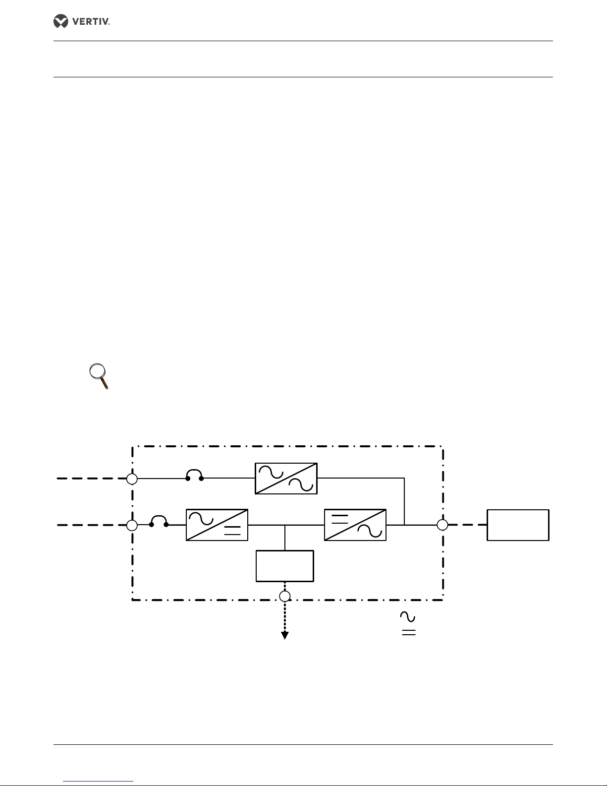
As shown in Figure 1, the AC utility source is input to the rectifier which converts the AC utility into DC power at
the DC bus operating voltage. This feeds the inverter and the DC/DC booster/charger. The inverter converts that
DC power from the rectifier—or DC power from the DC source (via the booster/charger)—into AC power for the
load.
The DC source will power the load through the inverter in the event of a power failure. When the system is being
powered by the utility, the booster/charger converts a portion of the DC power from the rectifier to a voltage
suitable for charging the batteries or other DC source. When the load is being powered by the DC source, the
booster/charger converts the DC source output to the voltage needed to drive the inverter.
The utility source can also power the load through the static bypass.
If maintenance or repair of the UPS is necessary, the load can be switched without interruption in service to an
external maintenance bypass.
Figure 1 Typical single module UPS system one-line diagram
NOTE
Vertiv recommends that the Liebert NX 225-600kVA always be installed with a maintenance bypass system that
fully isolates the UPS from the load and the AC power source. This allows service personnel to safely repair the
UPS if needed while maintaining power to the critical load.
Vertiv |Liebert
®
NX™ 225-600kVA Operation Manual 3

Introduction
1.2 MODES OF OPERATION
1.2.1 Normal Mode
Operating in normal mode, the Liebert NX's rectifier derives power from a utility AC source and supplies
regulated DC power to the inverter, which regenerates precise AC power to supply the connected equipment.
The rectifier also uses the utility source power to charge the DC sources.
1.2.2 Eco Mode
When the Liebert NX 225-600 kVA is in Eco Mode, the load will be supported by the bypass source as long as
the power quality of the bypass source remains within specified limits. This reduces energy consumption and
boosts efficiency to greater than 98%. If the power quality of the bypass source deviates from acceptable levels,
the inverter will take the load and the UPS will operate in normal mode. It will remain in normal mode until the
power quality of the bypass source has remained within limits for a suitable time, at which point the Liebert NX
will return to Eco Mode.
Eco Mode may be inhibited either automatically, such as when the Liebert NX is being fed by a generator source,
or manually, by sending a signal to one of the programmable input contacts. Examples of control circuits to
provide this functionality and a more detailed explanation of Eco Mode operation can be found in 2.6 - Eco Mode
Active.
1.2.3 Bypass Mode
When the Liebert NX is in bypass mode, the load is directly supported by utility power and is without DC source
backup protection.
The Liebert NX’s inverter and bypass static switch will shift the load from the inverter to bypass mode without an
interruption in AC power if the inverter is synchronous with the bypass and any of the following occurs:
• Inverter fails
• Inverter overload capacity is exceeded
• Inverter is manually turned Off by the user
• UPS is operating on battery and battery voltage reaches end of discharge level
NOTE
If the inverter is not in sync with the bypass, the static switch will transfer the load from the inverter to the
bypass WITH interruption in AC power to the critical load. The default interruption time is 16ms; the minimum is
4ms. Vertiv Liebert Services
™
can adjust the length of the interruption.
1.2.4 Battery Mode
When utility AC power fails, the Liebert NX protects the critical load by instantaneously channeling DC source
power to the inverter, which continues supporting the critical load without interruption.
When utility power returns and is within acceptable limits, the Liebert NX automatically shifts back to Normal
mode, with the rectifier powering the critical load.
1.2.5 Maintenance Bypass
The installation of a Maintenance Bypass Cabinet or Assembly is recommended to allow you to totally isolate the
UPS from all power sources. Use of the Maintenance Bypass is described in 2.0 - Operation.
®
Vertiv Liebert
NX™ 225-600kVA Operation Manual 4

Introduction
1.3 OPTIONS
A number of options are available from Vertiv for your UPS system. Some options are not available for all ratings.
Described below are the most frequently provided options. Other options are available. Contact your Vertiv sales
representative for more information.
•LIFE Services ™—A remote service delivery capability which enables the UPS to alert a special Liebert Services Support
Center to provide more efficient and proactive identification, resolution, and prevention of potential UPS issues.
• Network and BMS Connectivity and Monitoring—Communication cards support SNMP, Modbus or both (Dual Protocol)
• Battery and Racks—The batteries provide power in the event of a power outage. The Liebert NX UPS can use a variety of
battery types, provided the battery plant is designed for the UPS DC voltage range and the load requirements of your
application.
• Battery Cabinets—Valve-regulated, lead-acid (VRLA) sealed batteries are available in matching cabinets for convenient
installation and maintenance in otherwise unprotected space. Depending on the UPS module rating, two or more cabinets
may be connected in parallel to provide the additional run time.
• Module Battery Disconnect—The UPS system utilizes a separate Module Battery Disconnect for remotely located batteries.
A sensing circuit in the UPS module, set at the battery low voltage limit, trips the Module Battery Disconnect to safeguard
the battery from excessive discharge. The Module Battery Disconnect has an undervoltage release mechanism designed to
ensure that during any shutdown or failure mode all battery potential is removed from the UPS system.
• Battery DC Ground Fault Detection—Monitors battery ground fault current and generates a warning on the UPS
touchscreen LCD and other customer-specific annunciation options.
• Maintenance Bypass—This switchboard provides make-before-break maintenance bypass. It includes: Maintenance Bypass
Breaker (MBB) and Maintenance Isolation Breaker (MIB).
• Load Bus Synchronization—The Load Bus Sync (LBS) option keeps independent UPS systems (and therefore their critical
load buses) in sync, even when the modules are operating on DC source or asynchronous AC sources. This means that
critical loads connected to both load buses can switch seamlessly between the two.
• MultiBus Synch Module (MBSM)—Permits synchronizing operation of up to 11 UPS modules.
• Input Circuit Breaker—The UPS may be equipped with an internal input circuit breaker (CB1).
• Remote Status Panel—This option provides key status indicators. If ordered with your UPS, the power supply for this option
is factory installed. To add this option to a unit which has already been shipped contact Liebert Service.
• EPO (Emergency Power Off)—Your UPS may be equipped with an EPO button on its front panel near the operator touch
screen. Contacts for a remote EPO to be installed on site are also provided standard on all units.
• Temperature-Compensated Charging—When the battery temperature exceeds a preset limit (typically 77°F [25°C]), this
optional circuit proportionally reduces float charging voltage to prevent overcharging the battery.
• Battery Load Testing—When activated, this option forces the battery string to assume the load for a short period of time.
• Common Battery for Two Modules—Two Liebert NX 225-600kVA units may share a common battery plant if the following
conditions are met:
• The UPS modules are of the same capacity and their output is paralleled
• A Special Features Authorization (SFA) was ordered with the unit to include special current sensors (LEM’s)
• The system is configured as shown in Figure 40.
•No more than two UPS modules may share one battery.
®
Vertiv |Liebert
NX™ 225-600kVA Operation Manual 5
Operation
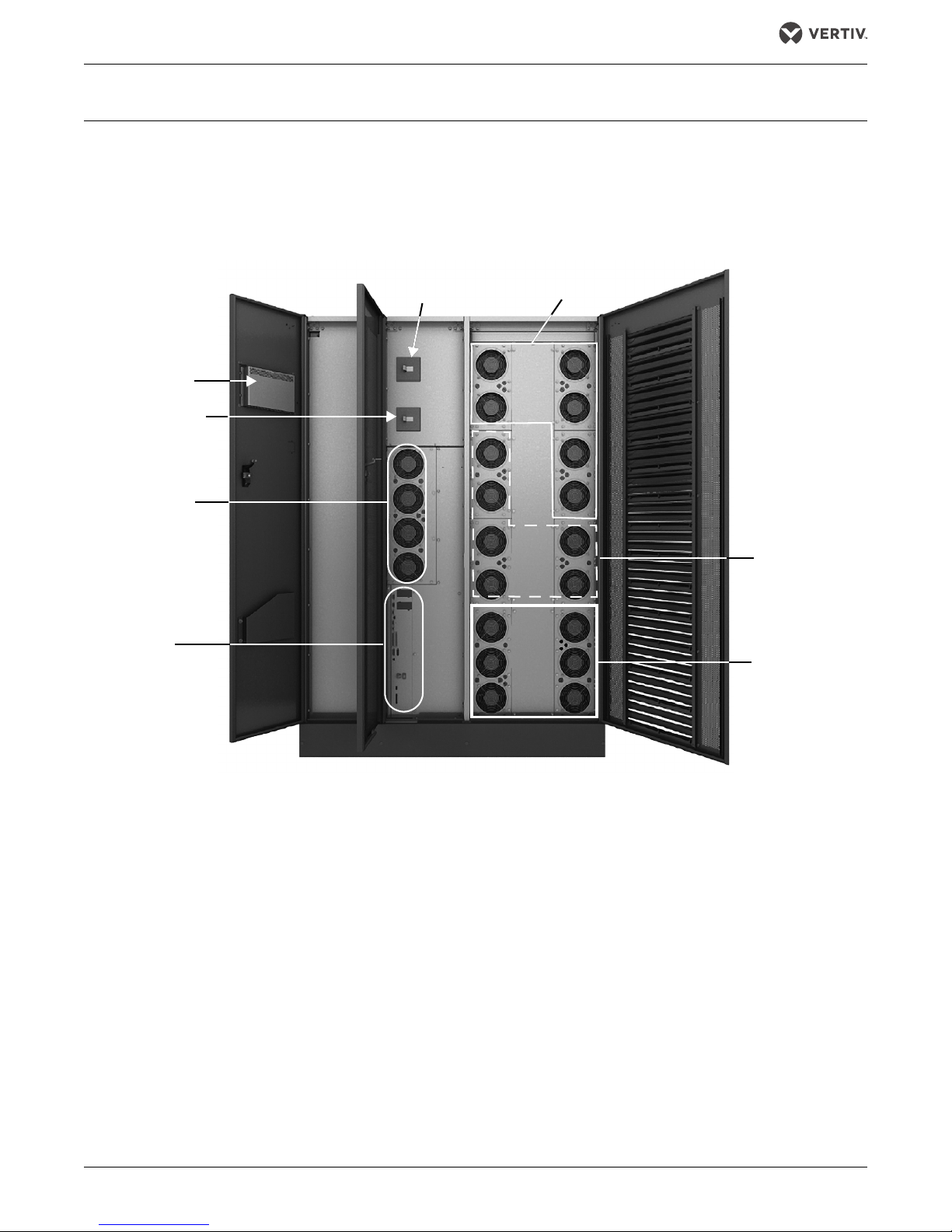
Input Circuit
Breaker, CB1
Back-Feed Circuit
Breaker, BFB
Static Switch
Subassembly
External
Communication
Panel (Comms
Options)
Rectifier
Subassemblies
Inverter
Subassemblies
DC-DC Converter
Subassemblies
Control LCD
2.0 OPERATION
The Liebert NX UPS is equipped with a microprocessor-based display touchscreen designed for convenient and
reliable operation. The display is driven by menu-prompted software.
2.1 PHYSICAL LAYOU T OF THE UPS
Figure 2 Main component locations—225-300kVA Liebert NX
Vertiv Liebert
®
NX™ 225-600kVA Operation Manual 6
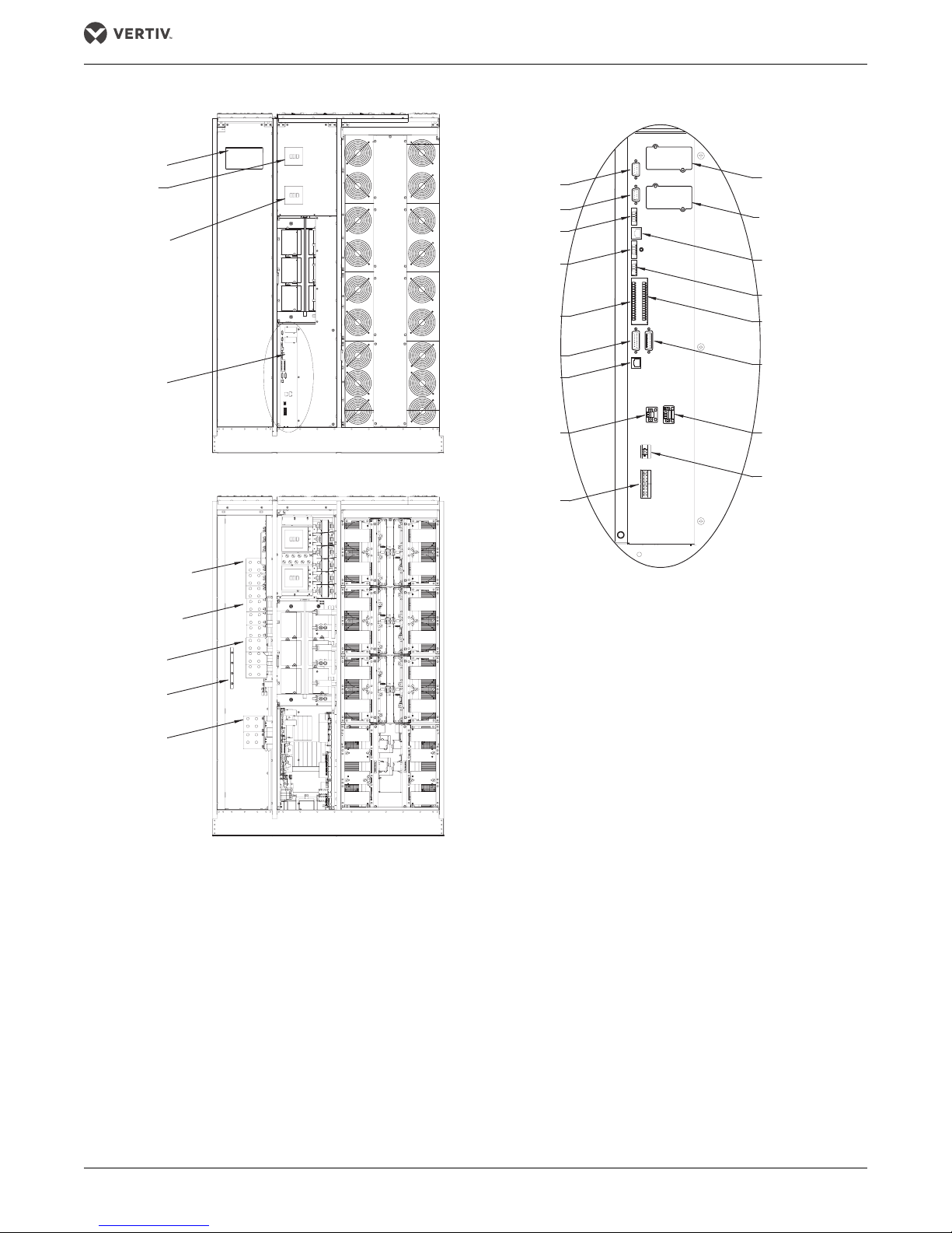
Figure 3 Main component details—225 to 300kVA Liebert NX
Operation
Control LCD
Main Input
Circuit Breaker
(CB1), optional
Backfeed Circuit
Breaker (BFB)
External
Communication
Panel, See Detail A
Bypass Busbars
Ø, A, B, C
Rectifier Input
Busbars Ø, A, B, C
Front Doors Removed
X6
XT1/2
XT3/8
TB2
X19A
X20
XT2
(Non-Functional)
TB3
(See specific control wiring drawings)
X3
Detail A
External Communication Panel
XS3
XS6 (LIFE)
X9
XT4
TB1
X19B
XT1
(Non-Functional)
XB4
Output Busbars
Ø, A, B, C
Input Ground
Busbar
Battery
Busbars (+ /-)
U38-3C-2000
Rev. 2
Doors and Inner Skins Removed
®
Vertiv |Liebert
NX™ 225-600kVA Operation Manual 7

Figure 4 Main component details, 400-600kVA Liebert NX
Control LCD
Main Input
Circuit Breaker
(CB1), optional
Backfeed Circuit
Breaker (BFB)
External
Communication
Panel, See
Detail A
Bypass Busbars
Ø, A, B, C
Rectifier Input
Busbars Ø, A, B, C
Input Ground
Busbar
Output
Busbars
Ø, A, B, C
Battery
Busbars (+ /-)
X3
XS3
X6
XT1/2
XT3/8
X19A
X20
X9
XT4
X19B
XT1
(Non-Functional)
XT2
(Non-Functional)
XS6 (LIFE)
TB2
TB3
TB4
TB1
Doors and Inner Skins Removed
Front Doors Removed
Detail A
External Communication Panel
(See specific control
wiring drawings)
U38-6C-2000
Rev. 2
Operation
2.2 INTERFACE DISPLAY FEATURES
The Liebert NX interface display enables the operator to perform such tasks as:
• Check operational status
• Monitor the power flow through the UPS system and all meter readings
• Execute operational procedures
• Check status reports and event files
• Adjustment programmable parameters
The touchscreen display has a blue background and multicolored text. The display turns On automatically, but
dims and the back-light goes out after 15 minutes of inactivity. Touching the screen will reactivate the back-light
for 15 minutes. If any screen other than the mimic screen is accessed, that screen will be displayed for 5 minutes
without any interaction. If there is no activity for 5 minutes, the display will revert to the basic mimic screen.
®
Vertiv Liebert
NX™ 225-600kVA Operation Manual 8
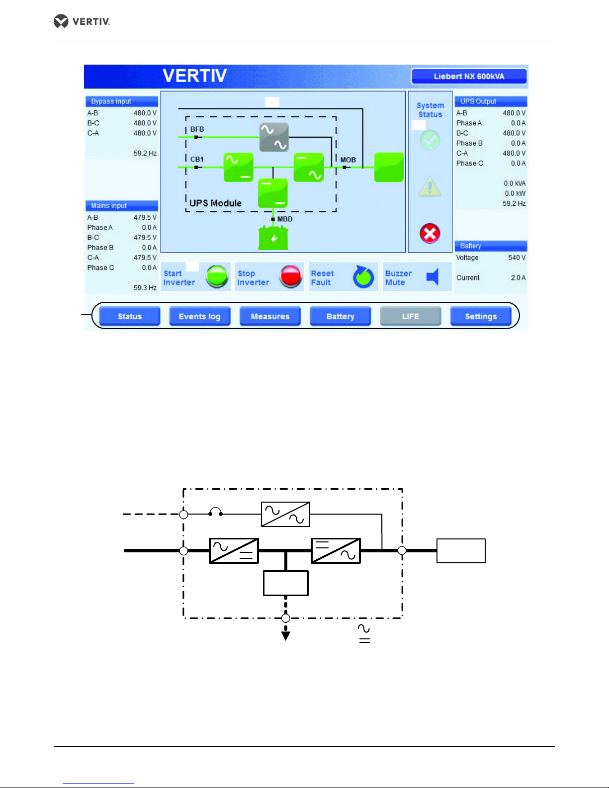
Figure 5 Main display screen, typical
4
1
3
5
9
2
6
8
7
1. Bypass Input: Voltage and frequency readings
2. Animated One Line Mimic
3. System Status
4. About Button
5. Output: Voltage, current and frequency readings
6. Battery: Voltage and current readings
7. Control Buttons
8. Menu Buttons
9. Line power Input: Voltage, current and frequency readings
Green
Gray
Green
Green
Green
COLOR CODE FOR ICONS
AND POWER PATH LINES
Green = OK and In the Active Power Path
Gray = Not Active
Yellow = Advisory
Red = Faulted or Disabled
Green
Critical
Load
BFB
UPS Module
To DC Supply
Module Rectifier
AC Input
Module Bypass
AC Input
UPS
Output
AC
DC
Booster/
Charger
Operation
Figure 6 Normal Mode
Vertiv |Liebert
®
NX™ 225-600kVA Operation Manual 9
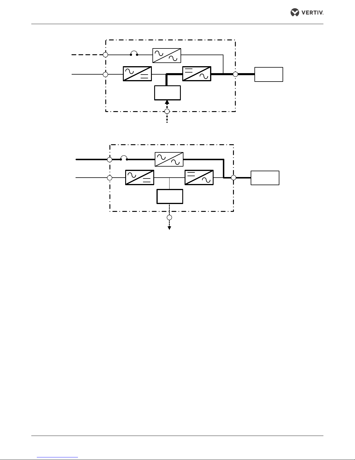
Figure 7 Utility fail
BFB
UPS Module
From DC Supply
Module Rectifier
AC Input
Module Bypass
AC Input
UPS
Output
Critical
Load
Booster/
Charger
BFB
UPS Module
To DC Supply
Module Rectifier
AC Input
Module By pass
AC Input
UPS
Output
Critical
Load
Booster/
Charger
Figure 8 Load on bypass
Operation
2.3 TOUCHSCREEN NAVI GATION
Several menu items can be accessed from the main display screen (see Figure 17). These menu items are
detailed in subsequent sections.
2.3.1 Main Display Screen
This is the default screen. It displays the following information:
• Bypass Input Voltage
• Bypass Input Frequency
• Input Voltage
•Input Current
• Input Frequency
• Output Voltage
•Output Current
• Output Frequency
• DC Source Voltage
• DC Source Current
®
Vertiv Liebert
NX™ 225-600kVA Operation Manual 10

Operation
System Status
Only one of the following three status indicators is actively highlighted at any given time:
System Normal Indicator—When the green check mark status icon (✔) is highlighted, the system is operating
normally and no warning or alarm has occurred. During line power failures (with all other conditions being
nominal), this icon is not highlighted.
Warning Indicator—The yellow triangle icon is activated and highlighted by abnormal conditions that could
affect the normal operation of the UPS. These conditions do not originate with the UPS, but may be caused
either by the surrounding environment or by the electrical installation (line power side and load side). A
description of the active warning(s) can be viewed by touching the yellow triangle or using the Status button at
the bottom of the page.
Fault Indicator—When the red circle with white cross is highlighted, immediate attention should be given to the
severity of the alarm, and service should be called promptly. A description of the active alarm(s) can be viewed
by touching the Status button at the bottom of the page.
No matter which indicator is active, all available diagnostic information on the unit can be displayed by touching
this area.
Control Buttons: Start Inverter and Stop Inverter—The touchscreen display features two buttons for starting and
shutting down the inverter. The start/stop control incorporates a safety feature for preventing accidental
operation. When the start or stop function for the inverter is selected, a pop-up window appears asking for
confirmation of the action.
Reset Fault—Reset faults (becomes red when there is a system fault).
Alarm Silence—Silence the buzzer in the case of an alarm.
NOTE
If screen is inactive for 30 seconds, the LCD will revert to the system status screen.
2.3.2 Status
This menu item displays a Status summary of warnings, faults and other events, as well as status screens for
each functional block, such as Rectifier, Inverter and Load.
®
Vertiv |Liebert
NX™ 225-600kVA Operation Manual 11
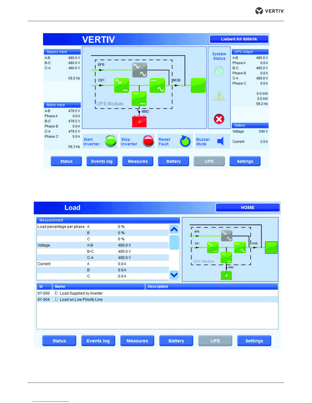
Figure 9 Main display screen, MBD open
In this case, the UPS is operating in double-conversion mode without power backup. All power paths (except the internal bypass and
maintenance bypasses lines) are green (active). The bypass static switch and the bypass lines are gray, indicating that they are not
active.
Green
Gray
Green
Green
Green
Red
Green
Green
Green
Green
Gray
Green
Operation
Figure 10 Load status
Vertiv Liebert
®
NX™ 225-600kVA Operation Manual 12
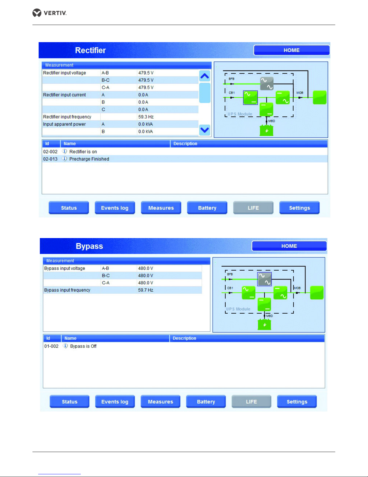
Figure 11 Rectifier status
Green
Gray
Green
Green
Green
Green
Green
Gray
Green
Green
Green
Green
Operation
Figure 12 Bypass status
®
Vertiv |Liebert
NX™ 225-600kVA Operation Manual 13
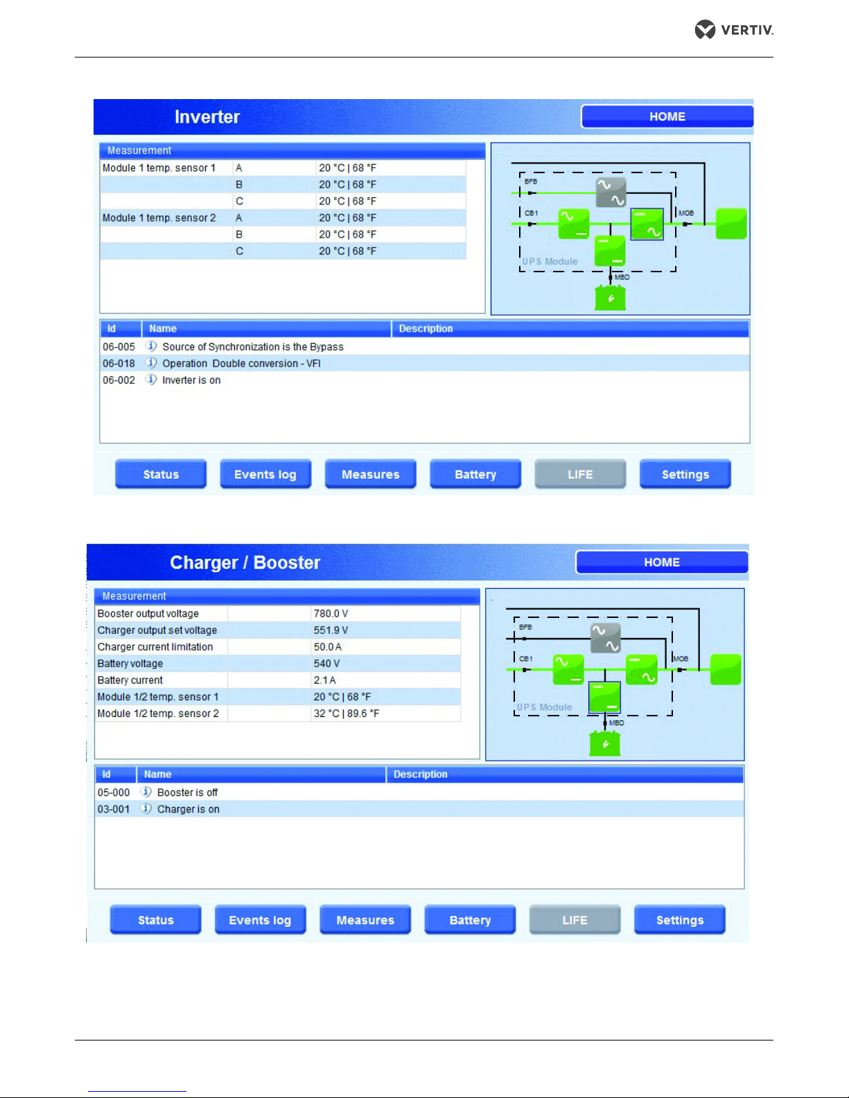
Figure 13 Inverter status
Green
Gray
Green Green
Green
Green
Green
Gray
Green Green
Green
Green
Operation
Figure 14 Charger/Booster status
®
Vertiv Liebert
NX™ 225-600kVA Operation Manual 14
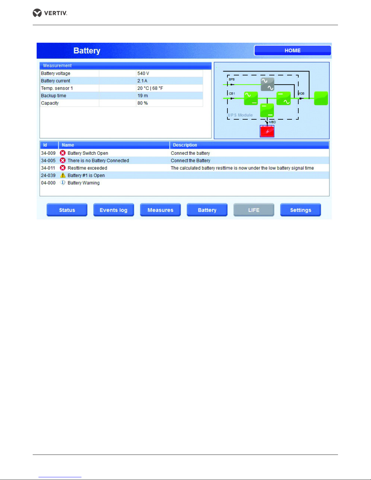
Figure 15 Battery status
Green
Gray
Green Green
Green
Red
Operation
®
Vertiv |Liebert
NX™ 225-600kVA Operation Manual 15
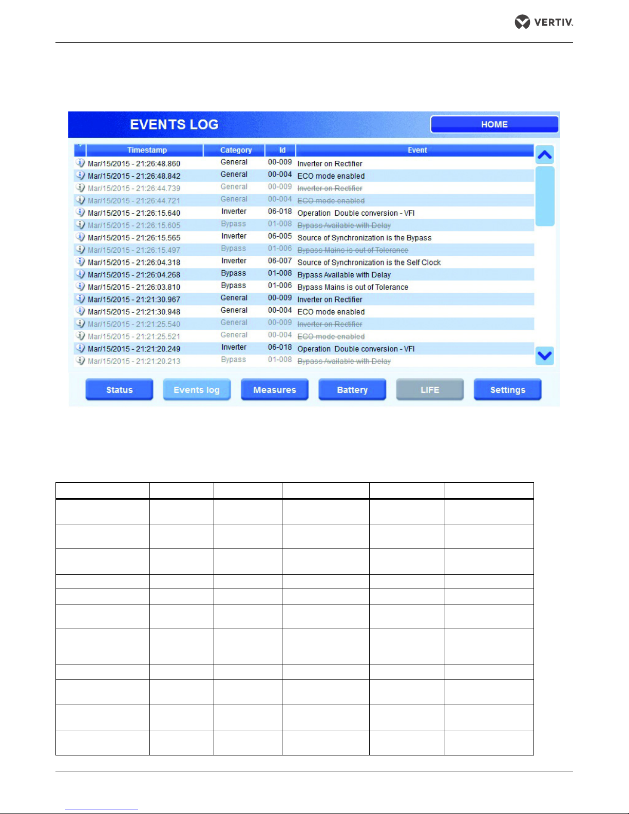
2.3.3 Events Log Menu
This menu item displays recent Events that occurred while the UPS was in operation.
Figure 16 Status summary
Operation
2.3.4 Measures Menu
This menu item displays the full set of measurements for each functional block (rectifier, bypass,
booster/charger, batteries, inverter and load).
Table 1 Measurements for functional blocks
Rectifier Bypass Inverter Charger/Booster Battery Load
Voltage - L-L Voltage - L-L Temperatures
Current - Phase Frequency —
Frequency — —
kVA per Phase — — Battery Voltage Backup Time kW per Phase
Temperatures — — Battery Current Capacity kVA per Phase
Rectifier
Output Voltage
Input Supervision
Counter
(# of Mains failures)
———— —Load%
———— —
———— —
———— —
— — Temperatures — Frequency
—— — —
Booster
Output Voltage
Booster Output
Voltage Setting
Charger Current
Limit
Battery Voltage % per phase
Battery Current Voltage L-L
Temperatures Current per Phase
Overload Time
Remaining
Tot a l Load
Power (kW)
Tot a l Load
Power (kVA)
Ambient
Tem pe ratu re
®
Vertiv Liebert
NX™ 225-600kVA Operation Manual 16
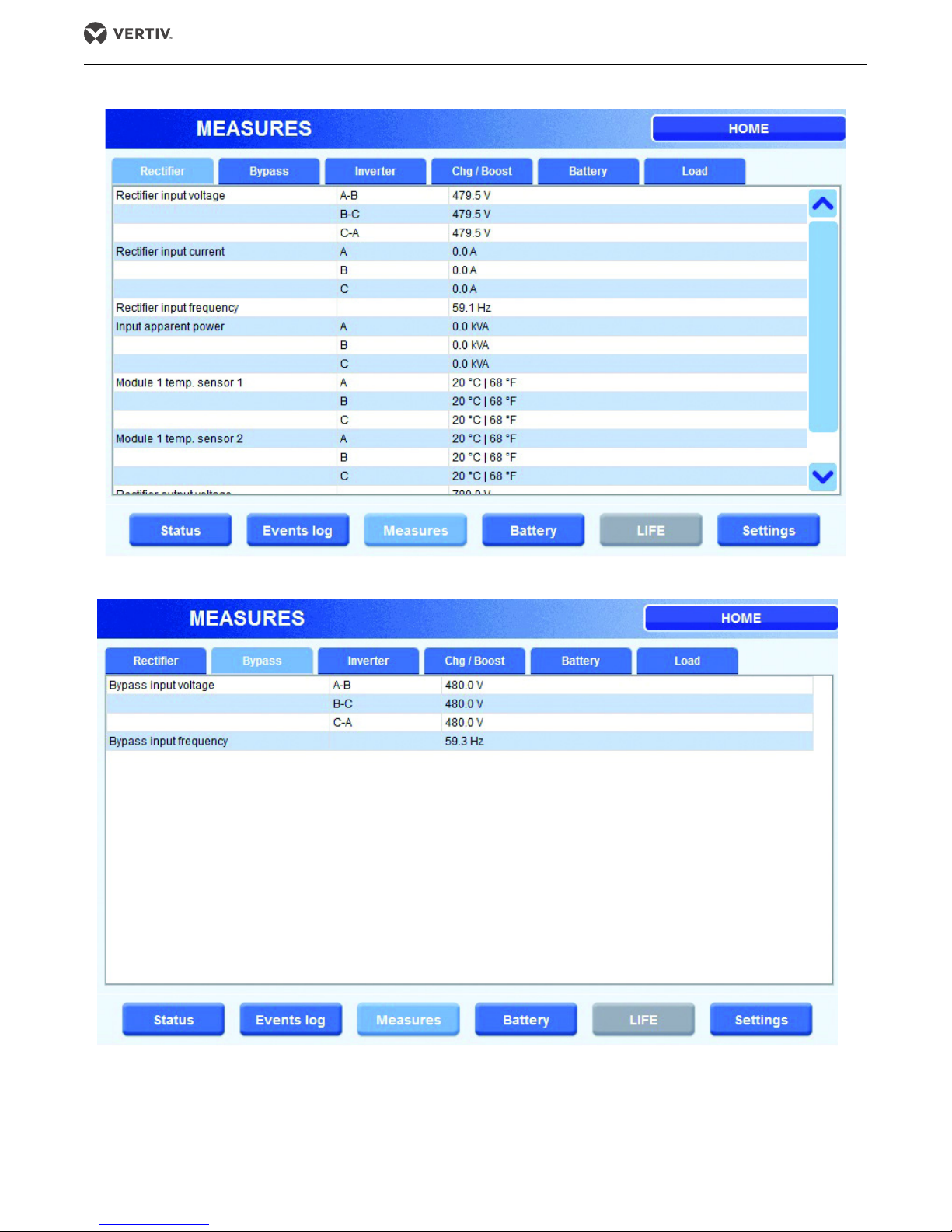
Figure 17 Rectifier measures
Operation
Figure 18 Bypass measures
®
Vertiv |Liebert
NX™ 225-600kVA Operation Manual 17
 Loading...