

Vertiv LIEBERT MPX PEM Quick Installation Manual
LIEBERT® MPX™ PEM
Quick Installation Guide
SL-20821_REV7
590-1624-501B
1
WAR NI NG: Before assembling and
installing a Liebert® MPX™, read
and understand all warnings and
cautions in the Liebert® MPX™
Rack Power Distribution Unit User
Manual which can be downloaded
at www.VertivCo.com.
Vertiv strongly recommends that
the MPX power entry module
(PEM) be installed by an individual
who is properly trained and
qualified to perform electrical work.
The MPX rack PDU contains high
voltage that can cause serious
personal injury or death. Install the
unit in a restricted-access location.
Connecting input power before the
MPX PEM is installed can cause arc
flash and can result in death. Do
not connect input power to the
MPX PEM until the MPX rack PDU
is fully assembled.
Do not connect more than one
MPX PEM to an MPX power rail
chassis (PRC). Installing more than
one MPX PEM will result in serious
injury or equipment damage.
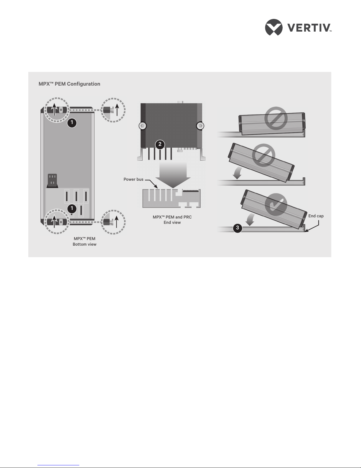
To attach an MPX™ PEM to an
MPX™ PRC:
1. Preparing for installation
Ensure the module’s circuit breaker
is in the o/open position and the
screw latches at each end of the
MPX PEM are positioned to fit into
the MPX PRC slot.
2. Aligning the MPX PEM power
blades
Position the MPX PEM so the power
blades align with the power bus on
the MPX PRC.
3. Positioning and connecting
the module to the MPX PRC
Hold the MPX PEM at an angle
against the MPX PRC end cap and
press down so that the MPX PEM
power blades engage firmly into the
MPX PRC power bus.
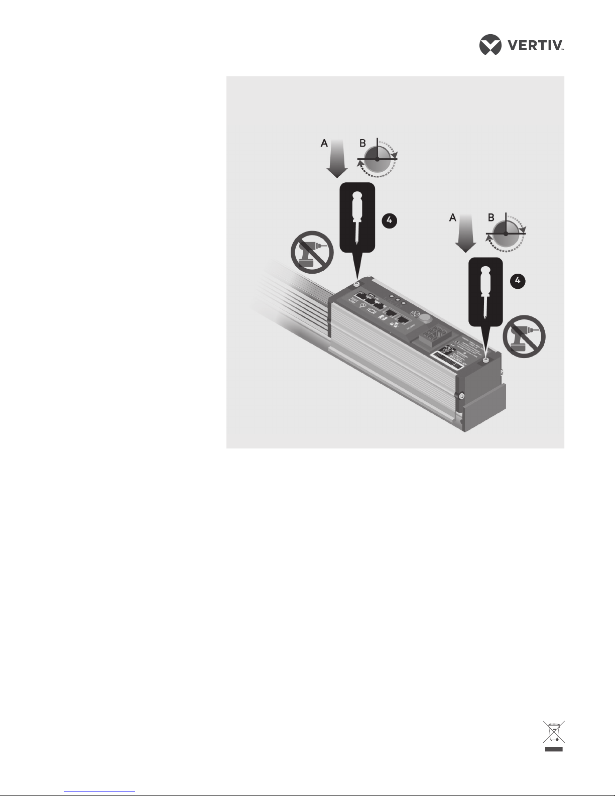
4. Securing the module to the
MPX PRC
Use the provided tamper-resistant
Torx™ (TR20) screwdriver bit to
press each screw latch downward.
Turn the screw latch 90 degrees
(one-quarter turn) to seat the
locking tab. Turn the screw latch an
additional 180 degrees (one-half
turn) until it locks.
WAR NI NG: Do not use power
tools or pneumatic equipment
to secure the screw latch.
Do not turn the screw latch
more than 270 degrees (a
three-quarter turn).
NOTE: If using a torquelimiting screwdriver, carefully
press the screw downward
first before turning. To prevent
MPX™ PEM
Bottom view
MPX™ PEM Configuration
End cap
1
1
2
3
MPX™ PEM and PRC
End view
Power bus
To contact Vertiv Technical Support: visit www.VertivCo.com
© 2017 Verti v Co. All rights res erved. Vertiv an d the Vertiv logo are tra demarks or regis tered trademar ks of Vertiv C o. All other names a nd logos referre d to are trade names ,
tradema rks or registere d trademarks of the ir respective ow ners. While ever y precaution ha s been taken to ensu re accuracy and co mpleteness h erein, Vertiv Co. a ssumes no
respon sibility, and disc laims all liabili ty, for damages res ulting from use of th is information or fo r any errors or omis sions. Speci fications are s ubject to change w ithout notice.
LIEBERT® MPX™ PEM
Quick Installation Guide
SL-20821_REV7
590-1624-501B
2
damage to the latches, do not
exceed a maximum torque of
18 in/lbs (2 Nm).
5. Verifying MPX™ PEM
installation
Conduct a visual inspection to verify
the MPX PEM has been properly
installed. A slight side-to-side
rocking of the module should not
cause separation from the MPX PRC
surface.
6. Connecting the MPX™ IPC
(for the MPXPEM-NVAXXAX
model only)
Insert the MPX IPC connector in the
MPX PEM installed on the MPX PRC.
See the MPX IPC Quick Installation
Guide for installation steps.
7. Installing the RPC web card
If used, install the optional
RPC™ web card. See the
RPC-1000™ Communications
Module Installer/User Guide or
the RPC2™ Communications
Module Installer/User Guide for
further instructions.
4
4
Securing the MPX™ PEM Screw Latches
 Loading...