

Vertiv Liebert Mini-Mate MT048, Liebert Mini-Mate MT036, Liebert Mini-Mate MT060 Installer/user Manual

Liebert®
Mini-Mate™ VariableCapacity
ThermalManagementSystems
Installer/User Guide
3, 4 and5 Ton(10.5, 14 and 17.5 kW) Capacity, Ceiling-mounted,60Hz

The information contained in this document is subject to change
without notice and may not be suitable for all applications. While
every precaution has been taken to ensure the accuracy and
completeness of this document, Vertiv assumes no responsibility
and disclaims all liability for damages resulting from use of this
information or for any errors or omissions. Refer to other local
practices or building codes as applicable for the correct methods,
tools, and materials to be used in performing procedures not
specifically described in this document.
The products covered by this instruction manual are manufactured
and/or sold by Vertiv This document is the property of Vertiv and
contains confidential and proprietary information owned by Vertiv.
Any copying, use or disclosure of it without the written permission
of Vertiv is strictly prohibited.
Names of companies and products are trademarks or registered
trademarks of the respective companies. Any questions regarding
usage of trademark names should be directed to the original
manufacturer.
Technical Support Site
If you encounter any installation or operational issues with your product, check the pertinent
section of this manual to see if the issue can be resolved by following outlined procedures.
Visit https://www.VertivCo.com/en-us/support/ for additional assistance.
Vertiv | Liebert® Mini-Mate™ Installer/User Guide

TABLE OF CONTENTS
1 Important Safety Instructions 5
1.1 Agency Listed 7
2 Nomenclature and Components 9
2.1 Mini-Mate Model-number Nomenclature 9
2.2 Component Location 10
3 Pre-installation Preparation andGuidelines 11
3.1 Planning Dimensions 11
3.2 Location Considerations 11
3.2.1 Location Considerations for Outdoor Condensing Unit 12
3.3 Connections and System Setup 12
3.4 Operating Conditions 12
3.4.1 Cooling, Humidification and Dehumidification 12
3.4.2 Heating 12
3.5 Mini-Mate Unit Weights 13
3.6 Equipment Inspection and Handling 13
4 Piping and Refrigerant Requirements 15
4.1 Refrigerant Piping and Charging 15
4.1.1 Refrigerant Piping Guidelines forAir-cooledSystems 16
4.2 Refrigerant-line Sizes and Equivalent Lengths 17
4.2.1 Refrigerant Charge Requirements 17
4.2.2 Additional Oil Requirements for Digital-scroll Compressors 18
4.3 Drain and Humidifier Piping 20
4.3.1 Water-supply line to the Humidifier 20
4.3.2 Drain Line Installation Requirements 20
4.3.3 Condensate-drain Pump Kit 22
5 Electrical Connection Requirements 23
5.1 Low-voltage Electrical Field Connections 24
6 Installation 27
6.1 Installing Ceiling-mounted Evaporators 27
6.1.1 Installing Suspension Rods andMounting Ceiling Units 27
6.2 Installing Air-distribution Components for Evaporators 28
6.2.1 Installing a Filter Box for 4-ton and 5-ton Models 28
6.2.2 Installing a Filter Box for 3-ton Models 28
6.2.3 Installing an Air-distribution Plenum for 3-ton Models 28
6.2.4 Installing a Bottom-discharge Grille for4-tonand5-tonModels 29
6.2.5 Guidelines for Ducted Systems 29
7 Checklist for Completed Installation 31
7.1 Moving and Placing Equipment 31
7.2 Electrical Installation Checks 31
7.3 Piping Installation Checks 31
7.4 Other Installation Checks 31
8 Initial Start-up Checks andCommissioning ProcedureforWarrantyInspection 33
9 Maintenance 35
9.1 Filters 35
9.1.1 Filter-replacement 36
9.2 Blower Drive System—EC Fans 37
9.2.1 Fan Impellers and Bearings Maintenance 37
Vertiv | Liebert® Mini-Mate™ Installer/User Guide | 3
9.2.2 Protective Features 37
9.2.3 Fan Assembly Troubleshooting 38
9.3 Direct-drive Blower System 41
9.3.1 Fan Impellers and Motor Bearings Maintenance 41
9.4 Steam-generating Humidifier Maintenance 41
9.4.1 Operating the Humidifier 42
9.4.2 Replacing the Canister 43
9.4.3 Circuit Board Adjustments 43
9.4.4 Humidifier Troubleshooting 44
9.5 Condensate-drain and Condensate-pump System Maintenance 44
9.5.1 Condensate Drain 44
9.5.2 Condensate Pump 45
9.6 Electric Reheat Maintenance 45
9.7 Thermostatic Expansion Valve (TXV) Maintenance 45
9.7.1 Determining Suction Superheat 45
9.7.2 Adjusting Superheat Setting with the TXV 45
10 Preventive Maintenance Checklist 47
Appendices 51
Appendix A: Technical Support and Contacts 51
Appendix B: Submittal Drawings 53
Vertiv | Liebert® Mini-Mate™ Installer/User Guide | 4
1 IMPORTANT SAFETY INSTRUCTIONS
SAVE THESE INSTRUCTIONS
This manual contains important safety instructions that should be followed during the installation and
maintenance of the Liebert®Mini-Mate. Read this manual thoroughly before attempting to install or
operate this unit.
Only qualified personnel should move, install or service this equipment.
Adhere to all warnings, cautions, notices and installation, operating and safety instructions on the unit
and in this manual. Follow all installation, operation and maintenance instructions and all applicable
national and local building, electrical and plumbing codes.
WARNING! Arc flash and electric shock hazard. Open all local and remote electric power-supply
disconnect switches, verify with a voltmeter that power is Off and wear appropriate,
OSHA-approved personal protective equipment (PPE) per NFPA 70E before working within the
electric control enclosure. Failure to comply can cause serious injury or death. Customer must
provide earth ground to unit, per NEC, CEC and local codes, as applicable. Before proceeding
with installation, read all instructions, verify that all the parts are included and check the
nameplate to be sure the voltage matches available utility power. The Liebert® controller does
not isolate power from the unit, even in the “Unit Off” mode. Some internal components require
and receive power even during the “Unit Off” mode of the controller. The only way to ensure
that there is NO voltage inside the unit is to install and open a remote disconnect switch. Refer
to unit electrical schematic. Follow all local codes.
WARNING! Risk of over-pressurization of the refrigeration system. Can cause explosive
discharge of high-pressure refrigerant, loss of refrigerant, environmental pollution, equipment
damage, injury, or death. This unit contains fluids and gases under high pressure. Use extreme
caution when charging the refrigerant system. Do not pressurize the system higher than the
design pressure marked on the unit's nameplate. Local building or plumbing codes may require
installing a pressure-relief device in the system.
Do not close off any field-installed, refrigerant-line isolation valves for repairs unless a
pressure-relief valve is field- installed in the line between the isolation valve and the check valve.
The pressure-relief valve must be rated 5% to 10% higher than the system-design pressure. An
increase in ambient temperature can cause the pressure of the isolated refrigerant to rise and
exceed the system-design pressure rating (marked on the unit nameplate).
WARNING! Risk of contact with high-speed, rotating fan impeller blades. Can cause injury or
death. Open all local and remote electric power-supply disconnect switches, verify with a
voltmeter that power is off, and verify that allfan impellers have stopped rotating before
working in the unit cabinet.
WARNING! Risk of electric shock. Can cause serious injury or death. The Liebert® iCOM
microprocessor does not isolate power from the unit, even in the "Unit Off" mode. Some internal
components require and receive power even during the "unit off" mode of the Liebert® iCOM
control. Open all local and remote electric power disconnect switches and verify with a
voltmeter that power is Off before working on any component of the system.
CAUTION: Risk of contact with sharp edges, splinters, and exposed fasteners. Can cause
injury. Only properly trained and qualified personnel wearing appropriate, OSHA-approved PPE
should attempt to move, lift, remove packaging from or prepare the unit for installation.
1 Important Safety Instructions 5

NOTICE
NOTICE
CAUTION: Risk of contact with hot surfaces. Can cause injury. The compressor, refrigerant
discharge lines, fan motor, and some electrical components are extremely hot during unit
operation. Allow sufficient time for them to cool to a touch-safe temperature before working
within the unit cabinet. Use extreme caution and wear appropriate, OSHA-approved PPE when
working on or near hot components.
Risk of oil contamination with water. Can cause equipment damage.
Liebert®Mini-Mate systems require the use of POE (polyolester) oil. POE oil absorbs water at a
much faster rate when exposed to air than previously used oils. Because water is the enemy of
a reliable refrigeration system, extreme care must be used when opening systems during
installation or service. If water is absorbed into the POE oil, it will not be easily removed and will
not be removed through the normal evacuation process. If the oil is too wet, it may require an oil
change. POE oils also have a property that makes them act as a solvent in a refrigeration
system. Maintaining system cleanliness is extremely important because the oil will tend to
bring any foreign matter back to the compressor.
Risk of improper refrigerant charging. Can cause equipment damage.
Refrigerant charge must be weighed into air-cooled compressorized systems before they are
started. Starting digital scroll compressors without proper refrigerant charging can cause the
compressors to operate at less than 5°F (–15°C) evaporator temperature and at less than
55psig (379kPa). Operation for extended periods at less than 55psig (379kPa) can cause
premature compressor failure.
NOTICE
NOTICE
Risk of clogged or leaking drain lines and leaking water-supply lines. Can cause equipment and
building damage.
This unit requires a water drain connection. Drain lines must be inspected at start-up and
periodically, and maintenance must be performed to ensure that drain water runs freely
through the drain system and that lines are clear and free of obstructions and in good
condition with no visible sign of damage or leaks. This unit may also require an external water
supply to operate.
Improper installation, application and service practices can result in water leakage from the
unit. Water leakage can result in catastrophic and expensive building and equipment damage
and loss of critical data center equipment.
Do not locate unit directly above any equipment that could sustain water damage.
We recommend installing a monitored fluid-detection system to immediately discover and
report coolant-fluid system and condensate drain-line leaks.
Risk of leaking water. Can cause equipment and building damage.
Improper installation, application, and service practices can result in water leakage from the
unit. Do not mount this unit over equipment and furniture that can be damaged by leaking
water. Install a water-tight drain pan with a drain connection under the cooling unit. We
recommend installing monitored leak detection equipment for the unit and supply lines. Check
drain lines periodically for leaks, sediment buildup, obstructions, kinks and/or damage and
verify that they are free running.
6
Vertiv | Liebert® Mini-Mate™ Installer/User Guide
NOTICE
NOTICE
NOTICE
Risk of improper water supply. Can reduce humidifier efficiency or obstruct humidifier
plumbing.
Do not use completely demineralized water with this unit. The water must contain minerals for
the electrode principle to work.
Do not use a hot water source. It will cause deposits that will eventually block the fill-valve
opening.
Risk of water backing up in the drain line. Leaking and overflowing water can cause equipment
and building damage.
Do not install an external trap in the drain line. This line already has a factory-installed trap
inside the cabinet. Installation of a second trap will prevent drain-water flow and will cause the
water to overflow the drain pan.
This line may contain boiling water. Use copper or other material that is rated for handling
boiling water for the drain line. Sagging condensate drain lines may inadvertently create an
external trap.
Risk of doorway/hallway interference. Can cause unit and/or structure damage. The unit may
be too large to fit through a doorway or hallway while on the skid. Measure the unit and
passageway dimensions, and refer to the installation plans prior to moving the unit to verify
clearances.
NOTICE
Risk of damage from forklift. Can cause unit damage. Keep tines of the forklift level and at a
height suitable to fit below the skid and/or unit to prevent exterior and/or underside damage.
NOTICE
Risk of improper storage. Can cause unit damage.
Keep the unit upright, indoors and protected from dampness, freezing temperatures and
contact damage.
1.1 Agency Listed
Standard 60-Hz units are CSA Certified to the harmonized U.S. and Canadian product safety standard
CSA C22.2 No 236/UL 1995 for “Heating and Cooling Equipment” and are marked with the CSA c-us logo.
1 Important Safety Instructions 7

This page intentionally left blank
8
Vertiv | Liebert® Mini-Mate™ Installer/User Guide
2 NOMENCLATURE AND COMPONENTS
This section describes the model number for Liebert® Mini-Mate units and components.
2.1 Mini-Mate Model-number Nomenclature
The tables below describe each digit of the 25-digitconfigurationnumber. The 14-digit model number
consists of the first 10 digits and last 4 digits of the configuration number.
Table 2.2 below describes each digit of the model number.
Table 2.1 Mini-Mate 25-digit Configuration Number
Model Number Digits 1 to 10 Model Details
1 2 3 4 5 6 7 8 9 10 11 12 13 14 15 16 17 18 19 20 21 22 23 24 25
M T 0 6 0 H E 1 A 0 S H 2 0 D 0 U 0 P 0 0 A # # #
Table 2.2 Model-number Digit Definitions
Digit and Description
Digits 1 and 2 = Unit Family
MT = Mini-Mate Ceiling System
Digits 3, 4, 5 = Nominal Cooling Capacity
036 = 36kBtuh
048 = 48kBtuh
060 = 60 kBtuh
Digit 6 = Air Direction and Discharge
H = Horizontal air flow
Digit 7 = System type
E = Split-system evaporator
Digit 8 = Fan type
1 = Direct-drive EC motor (variable-speed)
Digit 9 = Supplypower
A = 460V/ 3ph/ 60Hz
B = 575V/ 3ph/ 60Hz (048 and 060 models only)
C = 208V/ 3ph / 60Hz (048 and 060 models only)
D = 230V/ 3ph / 60Hz (048 and 060 models only)
P = 208-230/1ph/60Hz (036 model only)
Y = 208-230/3ph/60Hz (036 model only)
Digit 10 = Evaporator Type
0 =Split-system evaporator
Digit 11 = Humidifier
0 = No humidifier
S = Steam-gen canister humidifier
Digit 12 = Displaytype
H = 9-in. remote display, IntelliSlot-based monitoring (048 and 060 models only)
1 = 9-in. remote display, iCOM-based monitoring (036 model only)
ModelNumber
Digits11to14
2 Nomenclature and Components 9
Table 2.2 Model-number Digit Definitions (continued)
Digit and Description
Digit 13 = Reheat
0 = No reheat
2 = Electric reheat
5 = SCR reheat (048 and 060 models only)
Digit 14 = Coil, Valve, Pressure
0 = Split-system evaporator
Digit 15 = High-voltage options
D = Non-locking disconnect, 5k SCCR (048 and 060 models only)
L = Locking disconnect, 5kA SCCR (036 model only)
M = Locking disconnec t, 65k SCCR (048 and 060 models only)
Digit 16 = Low-voltage options
0 = None
L = Low-voltage terminal package (LVTP)
Digit 17 = Monitoring Cards
0 = No card, IntelliSlot only(048 and 060 models only)
U = IS-UNITY-DP card, factory-installed (048 and060 models only)
B = BACnet, Modbus, SNMP usingiCOM board (036 model only)
Digit 18 = Sensors
0 = None
S = Smoke sensor
H = High-temperature sensor
F = Smoke andhigh-temperature sensor
Digit 19 = Packaging
P = Domestic
C = Wood crate export
Digits 20, 21 = Future use
Digit 22 = Factory Configuration c ode
A = No SFA’s (Any Alphaletter except S)
S = SFA
Digit 23-25 = Factory Configuration Number
2.2 Component Location
The unit component locations are described in the submittal documents included in the Submittal
Drawings on page53.
The following tables list the relevant documents by number and title.
Table 2.3 Component-location Drawings
Document Number Title
DPN004808 Evaporator Unit, 3-ton
DPN004179 Evaporator Unit, 4-ton and 5-ton
10
Vertiv | Liebert® Mini-Mate™ Installer/User Guide
3 PRE-INSTALLATION PREPARATIONANDGUIDELINES
NOTE: Before installing unit, determine whether any building alterations are required to run piping,
wiring and ductwork. Follow all unit dimensional drawings and refer to the submittal engineering
dimensional drawings of individual units for proper clearances.
Refer to Model-number Digit Definitions on page9, and submittal drawings to determine the type of
system being installed and anticipate building alterations, piping and ductwork needed.
The unit dimensions, pipe-connection locations, and piping schematics are described in the submittal
documents included in the Submittal Drawings on page53.
• Confirm that the room is properly insulated and has a sealed vapor barrier.
• For proper humidity control, keep outside or fresh air to an absolute minimum (less than 5% of
total air circulated in the room).
• Install the units as close as possible to the largest heat load.
• Allow at least the minimum recommended clearances for maintenance and service. See the
appropriate submittal drawings for dimensions.
• We recommend installing a water detection system. Contact your Vertiv representative for
information.
3.1 Planning Dimensions
The unit dimensions described in the submittal documents included in the Submittal Drawings on
page53.
The following table lists the relevant documents by number and title.
Table 3.1 Dimension Planning Drawings
Document Number Title
DPN004800 Cabinet dimensions, 3-ton DX module
DPN004055 Cabinet dimensions, 4-ton and5-ton DX module
Filter andDucting Options
DPN004805 Dimensional data, Filter box and Duct Flange, 3-ton
DPN004807 Dimensionaldata, Air-distribution plenum 3-ton
DPN004166 Dimensional data, Filter box and Duct Flange, 4- and 5-ton
DPN004842 D imensionaldata, Bottom-discharge Grille, 4- and 5-ton
3.2 Location Considerations
The evaporator is usually mounted above the dropped ceiling and must be securely mounted to the roof
structure. For ducted systems, the evaporator may be located in a different room. See Guidelines for
Ducted Systems on page29, for additional guidelines. For a split system with an air-cooled, outdoor
condensing unit, the condensing unit may be mounted on the roof or remotely in an outdoor area. See
Location Considerations for Outdoor Condensing Unit on the next page, for additional guidelines.
Refer to Refrigerant-line Sizes and Equivalent Lengths on page17 for maximum refrigerant line lengths.
The ceiling and ceiling supports of existing buildings may require reinforcement. See Mini-Mate Unit
Weights on page13. Be sure to follow all applicable national and local codes.
Install the ceiling-mounted unit over an unobstructed floor space if possible. This will allow easy access for
routine maintenance or service. Do not attach additional devices (such as smoke detectors, etc.) to the
housing, as they could interfere with the maintenance or service.
Do not install units in areas where normal unit operating sound may disturb the working environment.
3 Pre-installation PreparationandGuidelines 11

3.2.1 Location Considerations for Outdoor Condensing Unit
Observe the following when planning the installation of the outdoor unit:
• To ensure a satisfactory air supply, locate air-cooled condensing units in an environment with
clear air, away from loose dirt and foreign matter that may clog the coil.
• Condensing units must not be located in the vicinity of steam, hot air or fume exhausts or
closer than 18 inches from a wall, obstruction or adjacent unit.
• Avoid areas where heavy snow will accumulate at air inlet and discharge locations.
• The condensing unit should be located for maximum security and maintenance accessibility.
Avoid ground-level sites with public access. Install a solid base, capable of supporting the
weight of the condensing unit.
• The base should be at least 2in. (51mm) higher than the surrounding grade and 2 in. (51mm)
larger than the dimensions of the condensing-unit base. For snowy areas, a base of sufficient
height to clear snow accumulation must be installed.
Before beginning, refer to Piping and Refrigerant Requirements on page15 for unit placement, piping
guidelines, and refrigerant-charge requirements for your system.
3.3 Connections and System Setup
• The unit requires a drain, which must comply with all applicable codes. This drain line may
contain boiling water. See Drain Line Installation Requirements on page20, for details.
• Electrical service is required for all models. Electrical service must conform to national and local
electrical codes. See equipment nameplate for details.
• Plan the routing of wiring, piping and ductwork to the unit. Refer to the appropriate piping
connection location drawings, piping schematics, and electrical-connection drawings for your
system in .
NOTE: Seal openings around piping and electrical connection to prevent air leakage. Failure to do so
could reduce the unit’s cooling performance.
3.4 Operating Conditions
The Liebert® Mini-Mate must be operated in a conditioned space within the operating envelope that
ASHRAE recommends for data centers. Operating the Mini-Mate outside of this envelope can decrease
equipment reliability. Refer to ASHRAE’s publication, “Thermal Guidelines for Data Processing
Environments.”
3.4.1 Cooling, Humidification and Dehumidification
For operation in the Cooling, Humidification or Dehumidification modes, the Liebert® Mini-Mate unit’s
return-air requirements for proper unit operation are:
• Maximum dew point of 59°F (15°C)
• Minimum 65°F (20°C)DB
• Maximum 85°F (29.4°C) DB
3.4.2 Heating
For operation in the Heating mode, the Liebert® Mini-Mate unit’s return-air requirements for proper unit
operation are:
• Maximum humidity: less than 80% RH and less than 64°F (17.8°C) dew point.
• Maximum dry bulb of 80°F (27°C)
12
Vertiv | Liebert® Mini-Mate™ Installer/User Guide
3.5 Mini-Mate Unit Weights
Table 3.2 Mini-Mate Unit weights
Model # Weight, lb (kg)
MT036 328 (149)
MT048 498 (22 6)
MT060 498 (226)
3.6 Equipment Inspection and Handling
SAFETY INFORMATION
WARNING! Risk of improper moving, lifting, or handling of the unit. Can cause equipment
damage, injury or death. Read all of the following instructions and verify that all lifting and
moving equipment is rated for the weight of the unit before attempting to move, lift, remove
packaging from or prepare the unit for installation. Unit weights are specified in section Table
3.2 above.
CAUTION: Risk of contact with sharp edges, splinters, and exposed fasteners. Can cause
injury. Only properly trained and qualified personnel wearing appropriate, OSHA-approved PPE
should attempt to move, lift, remove packaging from or prepare the unit for installation.
NOTICE
Risk of doorway/hallway interference. Can cause unit and/or structure damage. The unit may
be too large to fit through a doorway or hallway while on the skid. Measure the unit and
passageway dimensions, and refer to the installation plans prior to moving the unit to verify
clearances.
NOTICE
Risk of damage from forklift. Can cause unit damage. Keep tines of the forklift level and at a
height suitable to fit below the skid and/or unit to prevent exterior and/or underside damage.
NOTICE
Risk of improper storage. Keep the unit upright, indoors and protected from dampness,
freezing temperatures and contact damage.
Upon arrival of the unit and before unpacking:
• Verify that the labeled equipment matches the bill of lading.
• Carefully inspect all items for visible or concealed damage.
• Report damage immediately to the carrier and file a damage claim with a copy sent to Vertiv or
to your sales representative.
Equipment Recommended for Handling the Unit:
• Forklift
• Pallet jack
3 Pre-installation PreparationandGuidelines 13

This page intentionally left blank
14
Vertiv | Liebert® Mini-Mate™ Installer/User Guide

4 PIPING AND REFRIGERANT REQUIREMENTS
All fluid and refrigeration connections to the unit, with the exception of the condensate drain and
humidifier supply line, are sweat copper. Factory-installed piping brackets must not be removed. Fieldinstalled piping must be installed in accordance with local codes and must be properly assembled,
supported, isolated and insulated. Avoid piping runs through noise-sensitive areas, such as office walls
and conference rooms.
Refer to specific text and detailed diagrams in this manual for other unit-specific piping requirements.
The pipe connection locations, piping general arrangement and schematics are described in the
submittal documents included in the Submittal Drawings on page53.
The following tables list the relevant documents by number and title.
Table 4.1 Piping General-arrangment Drawings
Document Number Title
Air-cooled System
DPN004060 Piping arrangement, 3-, 4- and 5-ton split-system
Table 4.2 Piping Connection Drawings
Document Number Title
DPN004801 Primary connection locations, 3-ton DX module
DPN004806 Condensate-pump connection locations, 3-ton
DPN004056 Primary connection locations, 4-ton and 5-ton D X module
DPN004077 Condensate-pump connection locations, 4-ton and 5-ton
4.1 Refrigerant Piping and Charging
WARNING! Risk of over-pressurization of the refrigeration system. Can cause explosive
discharge of high-pressure refrigerant, loss of refrigerant, environmental pollution, equipment
damage, injury, or death. This unit contains fluids and gases under high pressure. Use extreme
caution when charging the refrigerant system. Do not pressurize the system higher than the
design pressure marked on the unit's nameplate. Local building or plumbing codes may require
installing a pressure-relief device in the system.
CAUTION: Risk of excessive refrigerant line pressure. Can cause tubing and component
rupture resulting in equipment damage and personal injury. Do not close off any field-installed
refrigerant-line isolation valves for repairs unless a pressure-relief valve is field- installed in the
line between the isolation valve and the check valve. The pressure-relief valve must be rated 5%
to 10% higher than the system-design pressure. An increase in ambient temperature can cause
the pressure of the isolated refrigerant to rise and exceed the system-design pressure rating
(marked on the unit nameplate).
Consult local building and plumbing codes for installation requirements of additional pressure-relief
devices when isolation valves are field installed. Do not isolate any refrigerant circuits from overpressurization protection.
4 Piping and Refrigerant Requirements 15

NOTICE
Risk of oil contamination with water. Can cause equipment damage.
Liebert®Mini-Mate systems require the use of POE (polyolester) oil. POE oil absorbs water at a
much faster rate when exposed to air than previously used oils. Because water is the enemy of
a reliable refrigeration system, extreme care must be used when opening systems during
installation or service. If water is absorbed into the POE oil, it will not be easily removed and will
not be removed through the normal evacuation process. If the oil is too wet, it may require an oil
change. POE oils also have a property that makes them act as a solvent in a refrigeration
system. Maintaining system cleanliness is extremely important because the oil will tend to
bring any foreign matter back to the compressor.
NOTICE
Risk of improper refrigerant charging. Can cause equipment damage.
Refrigerant charge must be weighed into air-cooled compressorized systems before they are
started. Starting digital scroll compressors without proper refrigerant charging can cause the
compressors to operate at less than 5°F (–15°C) evaporator temperature and at less than
55psig (379kPa). Operation for extended periods at less than 55psig (379kPa) can cause
premature compressor failure.
4.1.1 Refrigerant Piping Guidelines forAir-cooledSystems
• Evaporators and condensing units ship with an inert-gas holding charge. Do not vent the
evaporator and condensing unit until all refrigerant piping is in place, ready for connection to
the unit and condensing unit.
• Use copper piping with a brazing alloy with a minimum temperature of 1350°F (732°C), such as
Sil-Fos. Avoid soft solders, such as 50/50 or 95/5.
• Use a flow of dry nitrogen through the piping during brazing to prevent formation of copper
oxide scale inside the piping. When copper is heated in the presence of air, copper oxide forms.
POE oils will dissolve these oxides from inside the copper pipes and deposit them throughout
the system, clogging filter driers and affecting other system components.
• A pure dry nitrogen flow of 1-3 ft3/min (0.5-1.5 l/s) inside the pipe during brazing is sufficient to
displace the air. Control the flow using a suitable measuring device.
• Ensure that the tubing surfaces to be brazed are clean and that all burrs have been removed
from the ends of the tubes.
• Ensure that all loose material has been cleaned from inside the tubing before brazing.
• Protect all refrigerant line components within 18in. (460mm) of the brazing site by wrapping
them with a wet cloth or with a suitable heat-sink compound.
• Isolate piping from building using vibration-isolating supports.
• When sealing openings in walls and to reduce vibration transmission, use a soft, flexible
material to pack around the tubes to prevent tube damage.
• When installing remote condensing units above the evaporator, the suction gas lines should be
trapped at the evaporator. These traps will retain refrigerant oil in the off cycle. When the unit
starts, oil in the traps is carried up the vertical risers and returns to the compressors. For rises
over 25ft (7.6m), trap every 20ft (6m)or evenly-divided.
• Consult factory if piping run exceeds 150ft(46m) equivalent length.
• Keep piping clean and dry, especially on units with R-410A refrigerant.
• Avoid piping runs through noise-sensitive areas.
• Do not run piping directly in front of discharge air stream.
• Refrigerant oil – do not mix oil types.
Refer to ASHRAE Refrigeration Handbook for general, good-practice refrigeration piping.
NOTE: All indoor and outdoor suction-line piping must have 1/2 in. minimum of insulation. All outdoor
insulation must be UV and ozone resistant.
16
Vertiv | Liebert® Mini-Mate™ Installer/User Guide
NOTE: Proper safety equipment and proper refrigeration tools are required when working with R-410A
refrigerant. Check unit serial tag for correct refrigerant type before topping-off or recharging a system.
NOTE: Refrigerant R-410A uses a POE (polyolester) lubricant. The refrigerant must be introduced and
charged from the cylinder only as a liquid.
NOTE: When installing field piping, you must take care to protect all refrigerant lines from the
atmosphere especially when using refrigerants with POE oils. Do not allow the piping to stand open to
air for more than 15minutes. Units designed for R-410A have a compressor that contains POEoil,
which quickly absorbs water from the air. The longer that the refrigerant piping is left open to air, the
harder it will be to fully evacuate the system. If left open too long, the POE oil may require replacement
to achieve the required vacuum level.
• Refer to Refrigerant-line Sizes and Equivalent Lengths below,for recommended refrigerant
piping sizes based on equivalent pipe lengths.
• Refer to the condensing unit's Installer/User Guide for the complete charging procedure of the
system.
4.2 Refrigerant-line Sizes and Equivalent Lengths
The following tables list the information required to field-install the refrigerant piping for the system.
Table 4.3 Recommended refrigerant line sizes, O.D.cubyequivalentlength
Equivalent Length, ft (m)
System Models
50 (15) 75 (23) 100 (30) 125 (38) 150 (45)
MT036E/PFD037A-*L or PFD037A-*H
MT048HE/PFD054A-*L
MT060HE/PFD067A-*L
MT060HE/PFDZ67A-*L or PFD067A-*H
Consult factory for proper line sizing for runs longer than maximum equivalent length shown.
1.Use one line size smaller on suction lines for verticalrisers.
Suction line, in. 7/8 7/8 7/8 7/8 7/8
Liquid line, in. 1/2 1/2 1/2 1/2 1/2
Suction line, in. 7/8 1-1/8
Liquid line, in. 1/2 1/2 5/8 5/8 5/8
Suction line, in. 1-1/8 1-1/8 1-1/8 1-1/8 1-1/8
Liquid line, in. 1/2 5/8 5/8 5/8 5/8
Suction line, in. 1-1/8 1-1/8 1-1/8 1-1/8 1-1/8
Liquid line, in. 1/2 5/8 5/8 5/8 5/8
1
4.2.1 Refrigerant Charge Requirements
To calculate the charge requirements:
1. Determine the charge for your units by model number from the following tables.
2. Determine the charge for the piping by line size and length.
3. Add these all together to obtain the total refrigerant charge for your system.
Table 4.4 Indoor Evaporator Approximate R-410Arefrigerant charge
Model # Charge, lb (kg)
MT036HE 1 (0.45)
MT048HE 2.2 (1.0)
MT060HE 2.2 (1.0)
1-1/8
1
1-1/8
1
1-1/8
1
4 Piping and Refrigerant Requirements 17
Table 4.5 Interconnecting piping refrigerant charge for R-410A, lbper 100ft (kgper30m)
Line Size,
O.D., in.
3/8 3.2 (1.4) —
1/2 5.9 (2.7) 0.2 (0.1)
5/8 9.6 (4.3) 0.4 (0.2)
3/4 14.3 (6.4) 0.6 (0.3)
7/8 19.8 (8.8) 0.8 (0.4)
1-1/8 33.8 (15.1) 1.4 (0.6)
1-3/8 51.5 (23.0) 2.1 (1.0)
Source:DPN003099 Rev. 1
Liquid Line,lb (kg) Suction Line, lb (kg)
Table 4.6 Liebert® PFD R-410A refrigerant charge
Model # Charge, lb (kg)
PFD037A-*L1 13.4 (6.1)
PFD037A-*H1 27 (12.2)
PFD054A-*L1 27 (12.2)
PFD067A-*L1 27 (12.2)
PFDZ67A-*L1 57 (25.8)
PFD067A-*H1 57 (25.8)
4.2.2 Additional Oil Requirements for Digital-scroll Compressors
NOTICE
Risk of improper compressor lubrication. Can cause compressor and refrigerant system
damage.
Failure to use oil types, viscosities and quantities recommended by the compressor
manufacturer may reduce compressor life and void the compressor warranty.
• Do not mix polyolester (POE) and mineral-based oils.
• Do not mix oils of different viscosities.
• Consult your Vertiv sales representative, visit https://www.vertivco.com/en-us/support/,
or contact the compressor manufacturer if questions arise.
System charges may require additional oil charge to be added. See Table 4.7 on the facing page, for the
amount required for various system charge levels.
After the system has been fully charged with refrigerant, use a hand pump to add the additional oil at the
suction side of the system while the system is running.
On the tag marked “Oil Added Field Service Record,” attached to each compressor, record the date the oil
was added and the amount of oil added.
18
Vertiv | Liebert® Mini-Mate™ Installer/User Guide
Table 4.7 Additional oil required per refrigerant charge
Model
MT036HE/PFD037 MT048HE/PFD054 MT060HE, PFD067, PFDZ67
Refrigerant System
Charge per Circuit,
lb (kg) *
Additional Oil Required Per Circuit, oz (ml)
<40 (18.1) 0 0 0
40 (18.1) 4 (120) 4 (120) 6 (180)
50 (22.7) 6 (180) 6 (180) 9 (270)
60 (27.2) 8 (240) 8 (240) 12 (350)
70 (31.8) 10 (300) 10 (300) 15 (440)
80 (36.3) 12 (350) 12 (350) 18 (530)
* System Charge = indoor unit + condensing unit + refrigerant lines.
For system charges over 80lb. (36.3 kg), consult your Vertivrepresentative.
Source: DPN003950 Rev5.
Table 4.8 Compressor oil types for R-410A Refrigerant
Compressor Type Oil Type
CopelandScroll and Digital Scroll POE Oil - ISO 32 Centistoke Viscosity
1. Use CopelandPOE OilULTRA 32-3MAF or other Copeland-approved oils.
Source: DPN003950. Rev. 5
1
4 Piping and Refrigerant Requirements 19

4.3 Drain and Humidifier Piping
The following pipe connections are required:
• A drain line from the evaporator-unit drain connection.
• A drain line from the secondary drain pan (if applicable).
• A water-supply line to the optional humidifier (if applicable).
• On air-cooled systems: refrigerant piping connections between the evaporator unit and the
condensing unit. See Piping and Refrigerant Requirements on page15.
NOTICE
Risk of clogged or leaking drain lines and leaking water-supply lines. Can cause equipment and
building damage.
This unit requires a water drain connection. Drain lines must be inspected at start-up and
periodically, and maintenance must be performed to ensure that drain water runs freely
through the drain system and that lines are clear and free of obstructions and in good
condition with no visible sign of damage or leaks. This unit may also require an external water
supply to operate.
Improper installation, application and service practices can result in water leakage from the
unit. Water leakage can result in catastrophic and expensive building and equipment damage
and loss of critical data center equipment.
Do not locate unit directly above any equipment that could sustain water damage.
We recommend installing a monitored fluid-detection system to immediately discover and
report coolant-fluid system and condensate drain-line leaks.
4.3.1 Water-supply line to the Humidifier
The following is required for units with the optional steam-generating humidifier package:
• 1/4-in. (6.4mm) copper compression fitting connection for water inlet.
• The supply pressure range is 10psig to 150psig (69to1034kPa) at 1gpm (3.8(lpm).
• A shut-off valve in the supply line to isolate the humidifier for maintenance.
• Do not supply steam-generating humidifier with softened water.
• Do not use hot water source.
• Water conductivity must be in the range of 330-750micro-siemens.
To install the water supply:
1. Cut the tube square and remove any burrs.
2. Slide nut, then the sleeve on tube. The threaded end of the nut faces the end of the tube.
3. Insert the tube into the fitting, seating it against the stop shoulder and tighten the nut handtight to the body.
4. Use a wrench to tighten the nut 1-1/4 to 2-1/4 turns.
NOTICE
Risk of improper tightening of the piping fittings. Can damage fittings and cause leaks.
Use caution not to over-tighten or under-tighten the piping fittings.
Do not route the humidifier supply line in front of the filter-box access panel.
4.3.2 Drain Line Installation Requirements
20
NOTICE
Risk of water backing up in the drain line. Leaking and overflowing water can cause equipment
and building damage.
Vertiv | Liebert® Mini-Mate™ Installer/User Guide
Do not install an external trap in the drain line. This line already has a factory-installed trap
inside the cabinet. Installation of a second trap will prevent drain-water flow and will cause the
water to overflow the drain pan.
This line may contain boiling water. Use copper or other material that is rated for handling
boiling water for the drain line. Sagging condensate drain lines may inadvertently create an
external trap.
A 3/4 in. (19.1mm) NPT-female connection is provided for the evaporator-unit condensate drain. The
evaporator drain pan includes a float switch to prevent operation if the drain line becomes blocked. This
line also drains the humidifier, if applicable.
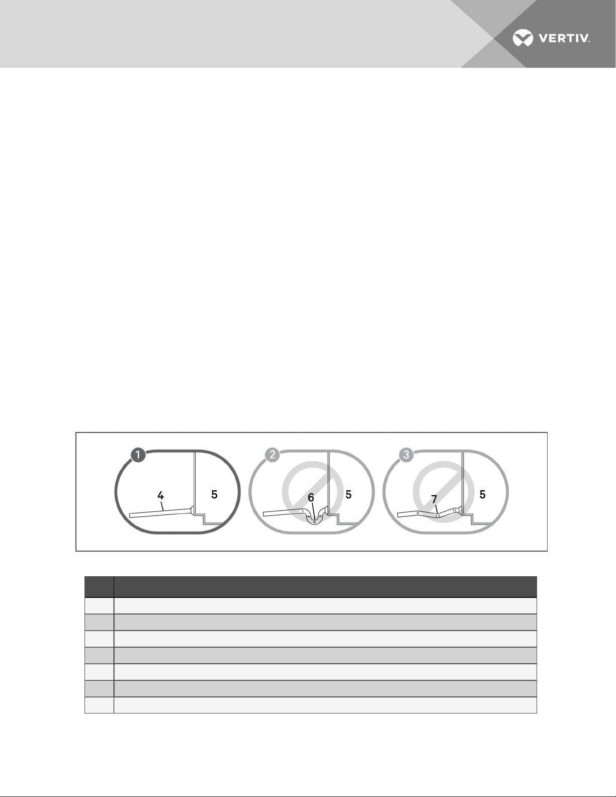
Observe the following requirements and refer to Figure 4.1 below, when installing and routing the drain
line:
• The drain line must be sized for 2gpm (7.6 l/m) flow.
• The drain line must be located so it will not be exposed to freezing temperatures.
• The drain should be the full size of the drain connection.
• The drain line must slope continuously away from the unit.
• Do not externally-trap the drain line.
• The drain line must be rigid enough that it does not sag between supports, which
unintentionally creates traps.
• Use copper or other material suitable for draining water that can reach temperatures up to
212°F (100°C).
• When the evaporator is installed below the level of the gravity-fed drain line, the optional
condensate pump kit is required. See Condensate-drain Pump Kit on the next page.
NOTE: Remove the shipping band from the float switch in the evaporator pan before operating the
unit.
Figure 4.1 Correct and Incorrect gravity drains
Table 4.9 Gravity-fed Drain Line Figure Descriptions
Item D escription
1 Correct drain installation.
2 Incorrect. Do not trap externally.
3 Incorrect. Sagging between supports and bowed line causes unintentionalexternal traps.
4 Continuous downward slope away from the unit.
5 Unit
6 External trap
7 Unintentional trapsfrom bowing of line. Lines must be rigid enough not to bow or sag between supports, creatinga trap.
4 Piping and Refrigerant Requirements 21
4.3.3 Condensate-drain Pump Kit
WARNING! Risk of electric shock. Can cause equipment damage, injury or death. Open all local
and remote electric power supply disconnect switches and verify with a voltmeter that power is
off before working within any electric connection enclosures. Service and maintenance work
must be performed only by properly trained and qualified personnel and in accordance with
applicable regulations and manufacturers’ specifications. Opening or removing the covers to
any equipment may expose personnel to lethal voltages within the unit even when it is
apparently not operating and the input wiring is disconnected from the electrical source.
The optional condensate pump kit is required when the evaporator is installed below the level of the
gravity-fed drain line. The condensate pump is field-installed alongside the evaporator unit.
A 3/4-in. NPT-Female connection is provided for the evaporator-unit condensate drain.
• The drain is trapped internally, do not trap external to unit.
• Size the discharge piping based on the available condensate head.
The pumps are rated as follows:
• 460-V condensate pump rated for 7.5 GPM (28.4 l/m) at 10-ft head pressure. The 460-V pump
is used on units with 575-V supply power.
• 208/230-V condensate pump rated for 5.1 GPM (19.3 l/m) at 10-ft head pressure.
The installation of the condensate-drain pump is described in the submittal documents included in the
Submittal Drawings on page53.
The following tables list the relevant documents by number and title.
Table 4.10 Condensate-drain Pump Drawings
Document Number Title
DPN004806 Condensate-pump connection locations, 3-ton models
DPN004077 Condensate-pump connection locations, 4- and5-ton models
22
Vertiv | Liebert® Mini-Mate™ Installer/User Guide
5 ELECTRICAL CONNECTION REQUIREMENTS
WARNING! Arc flash and electric shock hazard. Open all local and remote electric power-supply
disconnect switches, verify with a voltmeter that power is Off and wear appropriate,
OSHA-approved personal protective equipment (PPE) per NFPA 70E before working within the
electric control enclosure. Failure to comply can cause serious injury or death. Customer must
provide earth ground to unit, per NEC, CEC and local codes, as applicable. Before proceeding
with installation, read all instructions, verify that all the parts are included and check the
nameplate to be sure the voltage matches available utility power. The Liebert® controller does
not isolate power from the unit, even in the “Unit Off” mode. Some internal components require
and receive power even during the “Unit Off” mode of the controller. The only way to ensure
that there is NO voltage inside the unit is to install and open a remote disconnect switch. Refer
to unit electrical schematic. Follow all local codes.
WARNING! Risk of improper wire sizing/rating and loose electrical connections. Can cause
overheated wire and electrical connection terminals resulting in smoke, fire, equipment and
building damage, injury or death. Use correctly sized copper wire only and verify that all
electrical connections are tight before turning power On. Check all electrical connections
periodically and tighten as necessary.
NOTE: Seal openings around piping and electrical connections to prevent air leakage. Failure to do so
could reduce the unit's cooling performance.
NOTICE
Risk of improper electrical supply connection. Can cause equipment damage.
See transformer label for primary tap connections. Installer will need to change transformer
primary taps if applied unit voltage is other than pre-wired tap voltage.
NOTE: For 208-VAC, 3-ton applications, the low-voltage transformer tap must be changed. Refer to the
electrical schematic.
All power and control wiring and ground connections must be in accordance with the National Electrical
Code and local codes. Refer to the equipment serial-tag data for electrical requirements.
A manual electrical disconnect switch should be installed in accordance with local codes and distribution
system. Consult local codes for external disconnect requirements.
NOTE: Input-power requirements: For 3-phase units, only 3 power wires and an earth ground are
required.
The electrical connections are described in the submittal documents included in the Submittal Drawings
on page53.
The following table lists the relevant documents by number and title.
Table 5.1 Electrical Field-connection Drawings
Document Number Title
DPN004802 ElectricalField Connections, 3-ton DX Module
DPN004057 Electrical Field Connections, 4-ton and5-ton DX Module
DPN004238 4- and5-ton iCOM Wall-mount FieldConnection
DPN004803 3-ton iCOM Wall-mount Field Connection
5 Electrical ConnectionRequirements 23

Table 5.1 Electrical Field-connection Drawings (continued)
Document Number Title
Unit-to-Unit Networking
DPN004840 3-ton Model iCOM unit-to-unit field connection
DPN004841 4- and5-ton Models iCOM unit-to-unit field connection
5.1 Low-voltage Electrical Field Connections
Figure 5.1 on the facing page, shows an overview of the low-voltage wiring connections between the
Mini-Mate module and the condensing unit (on DX systems only), and the wiring and cabling between the
wall-mounted iCOM display for all system types. Detailed connection information is included in the
submittal drawings listed in Table 5.1 on the previous page.
Connect field-supplied, shielded, Class 1 wiring from the condensing unit to the indicated terminal-strip
locations.
For the wall-mounted iCOM-controller display:
• Connect a field-supplied, CAT5 Crossover Ethernet cable between P64 on the iCOM-control
board in the Mini-Mate module and ETH-1 on the wall-mount iCOM display.
• Locate the wire harness inside the wall-mount display, and connect field-supplied, Class 1
wiring between the harness and landing on the terminal-strip 13, 14, and 15 in the Mini-Mate
module to provide power for the display.
For the wall-mounted temperature/humidity sensor:
• Plug the factory-supplied, CANbus cable into P66 on the iCOM-control board in the Mini-Mate
module and into P66, Ethernet connection on the temperature/humidity sensor.
24
Vertiv | Liebert® Mini-Mate™ Installer/User Guide
 Loading...