

Vertiv Liebert Mini-Mate2 User Manual

Liebert® Mini-Mate2™
5Tons, 50&60Hz
User Manual

Technical Support Site
If you encounter any installation or operational issues with your product, check the pertinent section of
this manual to see if the issue can be resolved by following outlined procedures. Visit
https://www.VertivCo.com/en-us/support/ for additional assistance.

TABLE OF CONTENTS
1 Important Safety Instructions 7
2 Product Model Information 9
3 Introduction 15
3.1 Designed to Match Computer and Electronic Equipment Needs—From Installation to Operation 15
4 Standard Features—5 Ton Systems 17
4.1 Evaporator Section—Split System 17
4.2 Condensing Unit Section—Split System 17
4.2.1 Indoor Centrifugal Fan Condensing Units 17
4.2.2 Outdoor Prop Fan Condensing Units 17
4.2.3 Indoor Water/Glycol Condensing Units 17
4.3 Chilled Water Units 17
4.4 System Controls 18
4.4.1 Other Standard Control Features 18
5 Optional Factory-Installed Features - Evaporator/Chilled Water Units 19
5.1 Reheat 19
5.2 Humidifier 19
5.3 Sensors 19
5.4 Switches and Motors 19
5.5 Free-Cooling 20
5.6 Optional Configurations—Prop Fan Condensing Units 20
5.7 Optional Configurations—Water/Glycol Condensing Units 21
5.8 Optional Configurations—Chilled Water Units 21
6 Ship-Loose Accessories—Field-Installed 23
6.1 Remote Monitoring, Autochangeover and Leak Detection Equipment 23
7 Site Preparation and Installation 25
7.1 Installation Considerations 25
7.1.1 Room Preparation 26
7.1.2 Location Considerations 26
7.2 Ceiling Unit Weights 28
7.3 Equipment Inspection Upon Receipt 28
7.4 Installing the Ceiling Units 28
7.4.1 Close Coupled Installations 29
7.4.2 Evaporator Air Distribution 29
7.4.3 Piping Connections and Coolant Requirements 30
7.4.4 Electrical Connections 36
7.5 Indoor Air-Cooled Centrifugal Fan Condensing Unit Installation 39
7.5.1 Location Considerations 39
7.5.2 Electrical Connections 39
7.5.3 Piping Connections 40
7.5.4 Ducting 40
Vertiv | Liebert Mini-Mate2—5 ton User Manual| 3

7.6 Outdoor Air-Cooled Condensing Unit Installation 44
7.6.1 Location Considerations 44
7.6.2 Piping Connections 46
7.6.3 Electrical Connections 46
7.7 Indoor Water- and Glycol-Cooled Condensing Unit Installation 47
7.7.1 Location Considerations 47
7.7.2 Electrical Connections 47
7.7.3 Piping Connections 47
7.8 Optional Equipment Piping 52
7.8.1 Free-Cooling Coil 52
7.8.2 Hot Water Reheat Coil 52
7.9 Checklist for Completed Installation 54
8 Microprocessor Control 55
8.1 Feature Overview 55
8.2 Main Menu <Menu> 56
8.3 Setpoints 57
8.4 Status 57
8.5 Active Alarms 57
8.6 Time 58
8.7 Date 58
8.8 Setback 58
8.9 Setup Operation 58
8.9.1 Restart Time Delay 59
8.9.2 C/F Degrees 59
8.9.3 Humidity Control Method 59
8.9.4 Show DIP Switch 59
8.9.5 Valve Time (for Systems With a Modulating Chilled Water Valve) 59
8.9.6 CW Flush (for Systems with a Modulating Chilled Water Valve) 60
8.10 Change Passwords 60
8.11 Calibrate Sensors 60
8.12 Alarm Enable 61
8.13 Alarm Time Delay 61
8.14 Common Alarm Enable 61
8.15 Custom Alarms 62
8.15.1 Standard Custom Alarm Messages 62
8.16 Custom Text 62
8.17 Run Diagnostics (Available On Rev 1.001.0 and higher) 63
9 System Performance Microprocessor Controls 69
9.1 Temperature Control 69
9.1.1 Cooling/Heating Required 69
9.1.2 Cooling Operation (Compressorized Direct Expansion and Chilled Water) 69
9.1.3 Heating Operation 69
Vertiv | Liebert Mini-Mate2—5 ton User Manual| 4

9.2 Humidity Control 70
9.2.1 Dehumidification/Humidification Required 70
9.2.2 Dehumidification Operation, Compressorized Direct Expansion (DX) Systems 70
9.2.3 Humidification Operation 70
9.3 Load Control Features 70
9.3.1 Communications 70
10 Alarms 71
10.1 Alarms: Definitions and Troubleshooting 71
10.1.1 Custom Alarms 71
10.1.2 High Head Pressure 72
10.1.3 Humidity Level 72
10.1.4 Temperature 73
10.1.5 Humidifier Problem Alarm 73
10.1.6 High Water Alarm 73
10.1.7 Loss of Power 73
10.1.8 Short Cycle 73
10.2 Optional/Custom Alarms 73
10.2.1 Change Filter 73
10.2.2 High Temperature Sensor 74
10.2.3 Smoke Sensor 74
11 System Operation, Testing and Maintenance 75
11.1 System Testing 75
11.1.1 Environmental Control Functions 75
11.1.2 Cooling 75
11.1.3 Heating 75
11.1.4 Humidification 75
11.1.5 Dehumidification 75
11.1.6 Remote Shutdown 75
11.2 Maintenance and Component Operation 76
11.2.1 Electric Panel 76
11.2.2 Filters 76
11.2.3 Blower System 76
11.2.4 Blower Removal 76
11.2.5 Refrigeration System 77
11.3 Replacement Procedures 80
11.3.1 Compressor Replacement 80
11.3.2 Electrical Failure 80
11.3.3 Steam Generating Humidifier-Operation Procedures 81
11.3.4 Humidifier Circuit Board Adjustments 83
12 Maintenance Inspection Checklist 85
13 Troubleshooting 87
Vertiv | Liebert Mini-Mate2—5 ton User Manual| 5

Vertiv | Liebert Mini-Mate2—5 ton User Manual| 6

1 IMPORTANT SAFETY INSTRUCTIONS
Save These Instructions
This manual contains important safety instructions that should be followed during the installation and
maintenance of the Liebert Mini-Mate2. Read this manual thoroughly before attempting to install or
operate this unit. Only properly trained and qualified personnel should move, install or service this
equipment. Adhere to all warnings, cautions and installation, operating and safety instructions on the unit
and in this manual. Follow all installation, operation and maintenance instructions and all applicable
national and local building, electrical and plumbing codes.
WARNING! Arc flash and electric shock hazard. Disconnect all electric power supplies and wear
protective equipment per NFPA 70E before working within electric control enclosure. Failure to
comply can cause serious injury or death. Customer must provide earth ground to unit, per
NEC, CEC and local codes, as applicable. Before proceeding with installation, read all
instructions, verify that all the parts are included and check the nameplate to be sure the
voltage matches available utility power. The Liebert microprocessor control does not isolate
power from the unit, even in the Unit Off mode. Some internal components require and receive
power even during the Unit Off mode. The line side of the disconnect switch on the front of the
unit contains live high voltage. The only way to ensure that there is NO voltage inside the unit is
to install and open a remote disconnect switch and check the internal power supply wires with
a voltmeter. Refer to unit electrical schematic. Follow all applicable national and local electric
codes.
WARNING! Risk of explosive discharge from high-pressure refrigerant. Can cause injury or
death. This unit contains fluids and gases under high pressure. Relieve pressure before
working with piping.
WARNING! Risk of refrigerant system rupture or explosion from overpressurization. Can cause
equipment damage, injury or death. If a pressure relief device is not provided with the
condenser unit, the system installer must provide and install a discharge pressure relief valve
per national and local codes in the high side refrigerant circuit. Do not install a shutoff valve
between the compressor and the field-installed relief valve. Do not isolate any refrigerant
circuits from overpressurization protection.
WARNING! Risk of high-speed moving parts. Can cause injury or death. Open all local and
remote electrical power disconnect switches, verify with a voltmeter that power is Off and the
blower, pulleys and belts have stopped moving before working in the unit cabinet.
CAUTION: Risk of contact with hot surfaces. Can cause injury. The refrigerant discharge lines,
humidifiers and reheats are extremely hot during unit operation. Allow sufficient time for them
to cool before working within the unit cabinet. Use extreme caution and wear protective gloves
and arm protection when working on or near hot discharge lines, humidifiers and reheats.
Vertiv | Liebert Mini-Mate2—5 ton User Manual| 7

NOTICE
NOTICE
CAUTION: Risk of sharp edges, splinters and exposed fasteners. Can cause injury. Only
properly trained and qualified personnel wearing appropriate safety headgear, gloves, shoes
and glasses should attempt to move the unit, lift it, remove packaging from or prepare the unit
for installation.
Risk of leaking water. Can cause equipment and building damage.
Improper installation, application and service practices can result in water leakage from the
unit. Do not mount this unit over equipment or furniture that can be damaged by leaking
water. Install a watertight drain pan with a drain connection under the cooling unit and the
ceiling mounted water/glycol condenser unit. Route the drain line to a frequently used
maintenance sink so that running water can be observed and reported in a timely manner.
Post a sign to alert people to report water flowing from the secondary drain pan. Vertiv™
recommends installing monitored leak detection equipment for unit and supply lines and in
the secondary drain pan. Check drain lines periodically for leaks, sediment buildup,
obstructions, kinks and/or damage and verify that they are free running.
Risk of a leaking coil due to freezing and/or corrosion. Can cause equipment and building
damage.
Cooling coils and piping systems that are connected to open cooling towers or other open
water/glycol systems are at high risk for freezing and premature corrosion. Fluids in these
systems must contain the proper antifreeze and inhibitors to prevent freezing and premature
coil corrosion. The water or water/glycol solution must be analyzed by a competent water
treatment specialist before startup to establish the inhibitor requirement. The water or
water/glycol solution must be analyzed every six months to determine the pattern of inhibitor
depletion. The complexity of water-caused problems and their correction makes it important to
obtain the advice of a water treatment specialist and follow a regularly scheduled maintenance
program.
NOTICE
Risk of damage from forklift. Can cause unit damage.
Keep tines of the forklift level and at a height suitable to fit below the skid and/or unit to
prevent damage.
NOTICE
Risk of improper storage. Can cause unit damage.
Keep the Liebert Mini-Mate2 upright, indoors and protected from dampness, freezing
temperatures and contact damage.
Vertiv | Liebert Mini-Mate2—5 ton User Manual| 8
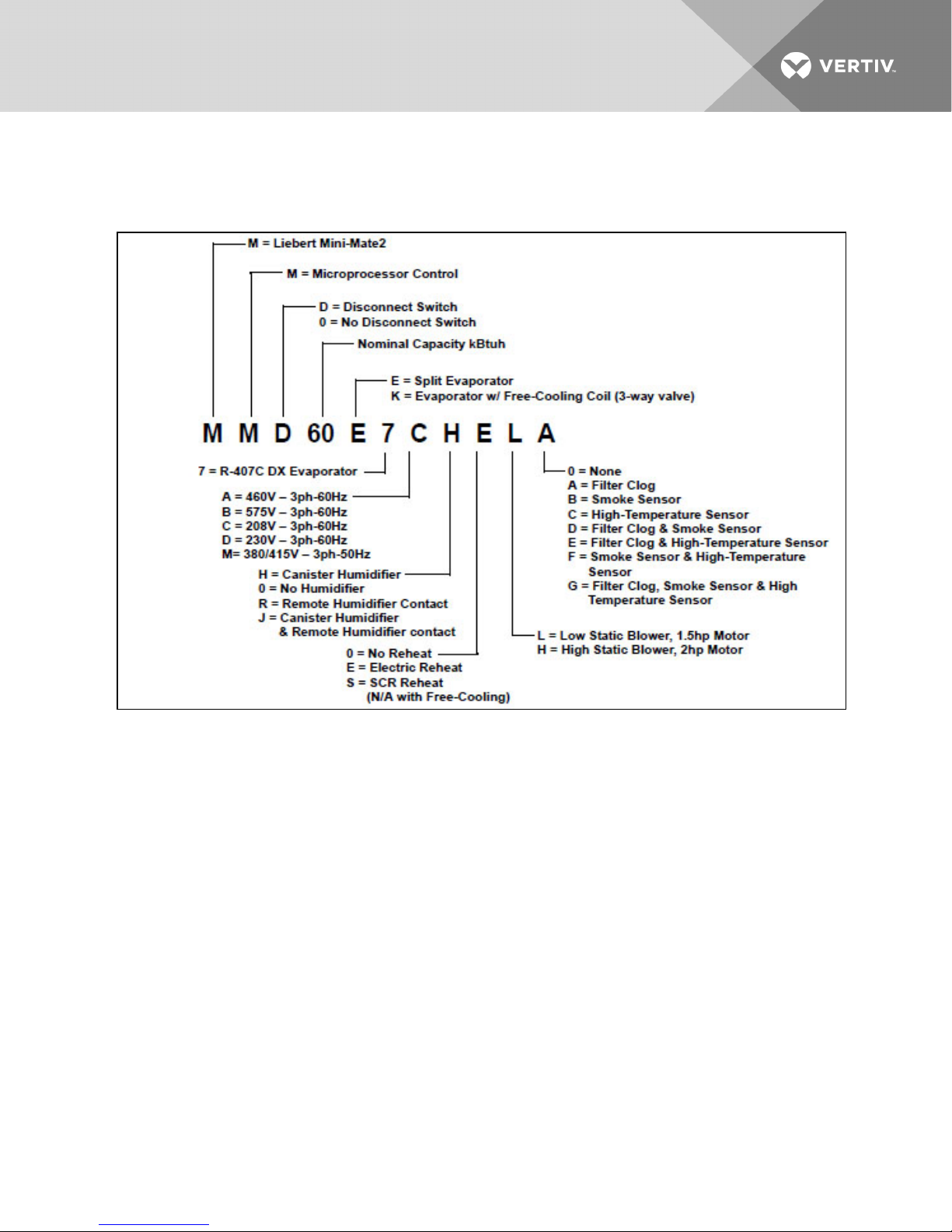
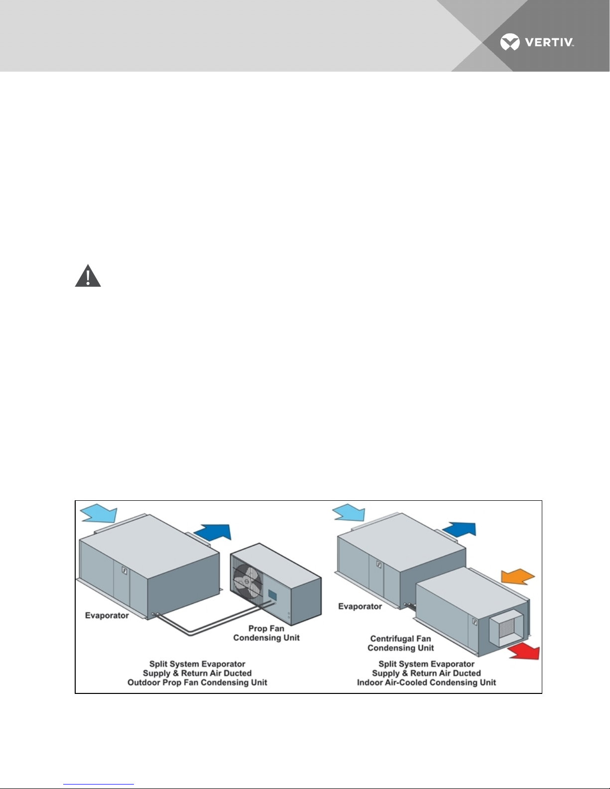
2 PRODUCT MODEL INFORMATION
Figure 2.1 Split system evaporators
Vertiv | Liebert Mini-Mate2—5 ton User Manual| 9
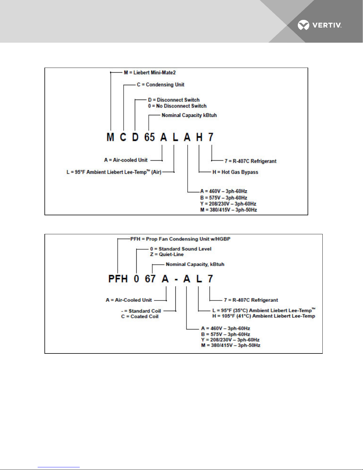
Figure 2.2 Air-cooled systems—indoor centrifugal condensing units
Figure 2.3 Air-cooled systems—outdoor prop fan condensing units
Vertiv | Liebert Mini-Mate2—5 ton User Manual| 10
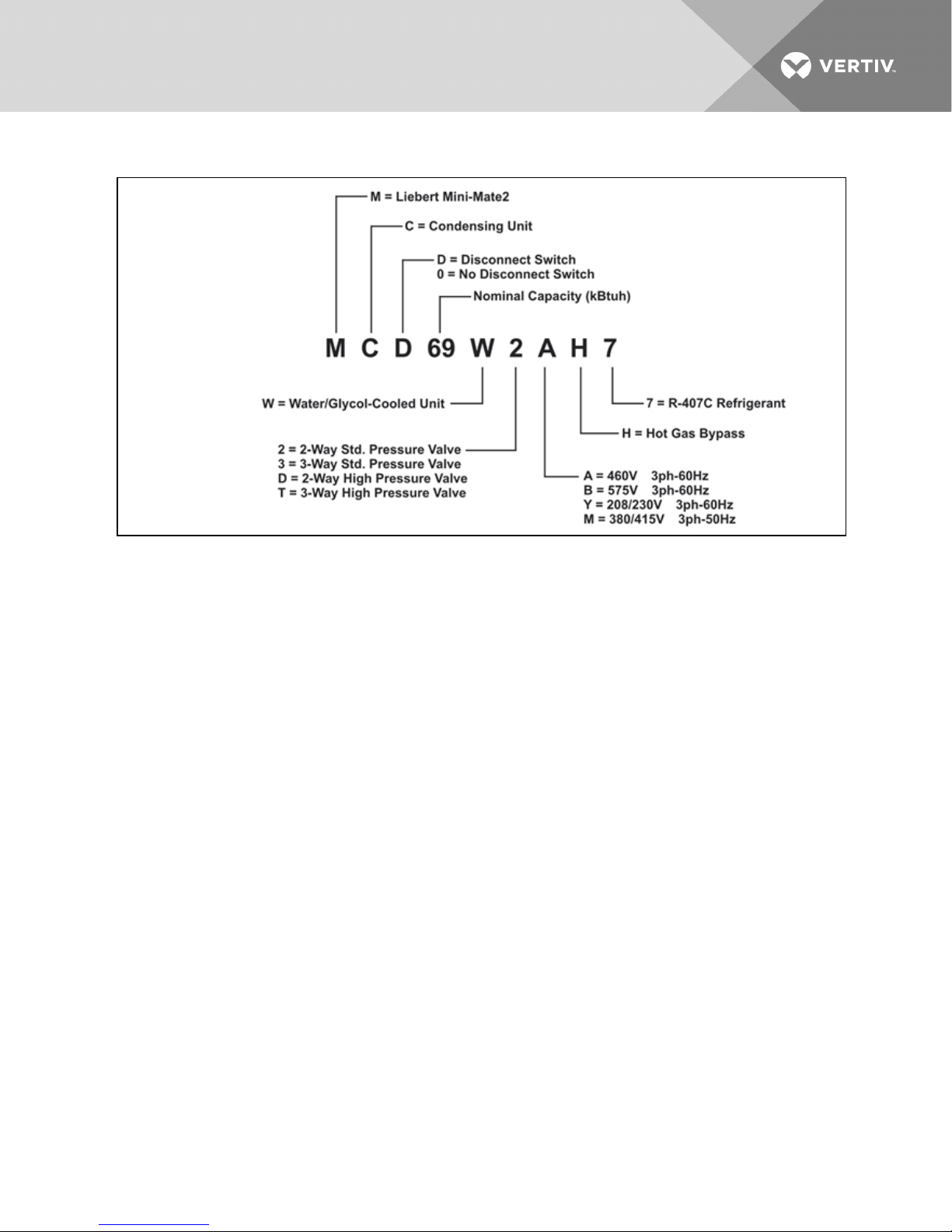
Figure 2.4 Water/glycol-cooled systems—indoor condensing units
Vertiv | Liebert Mini-Mate2—5 ton User Manual| 11
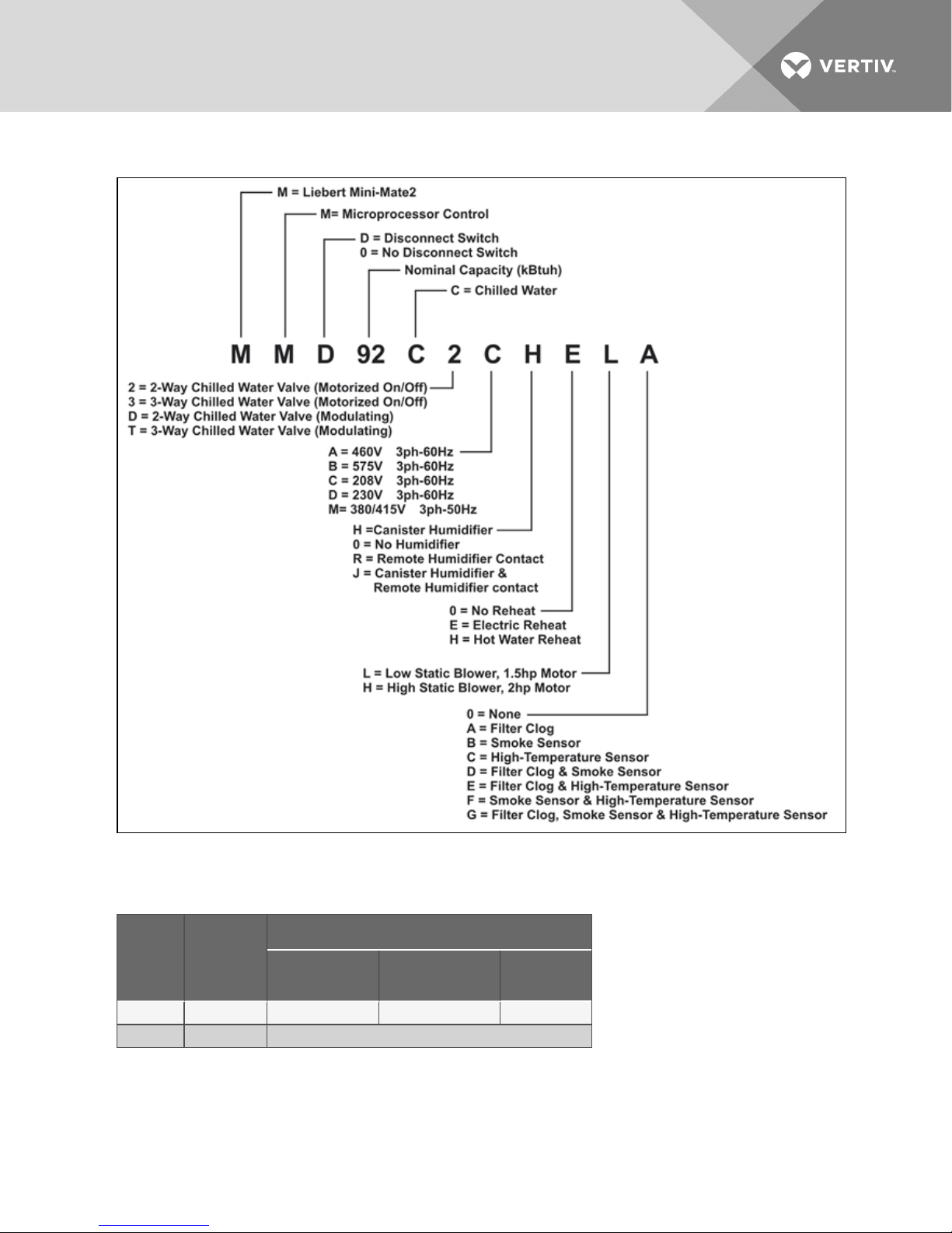
Figure 2.5 Chilled water systems
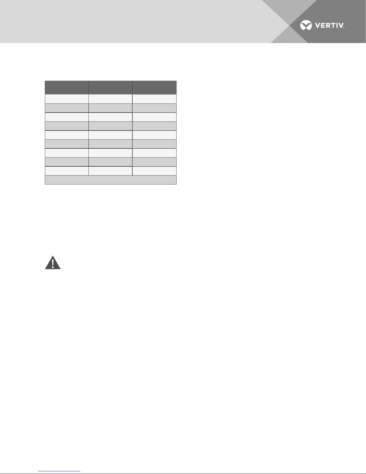
Table 2.1 System configurations—60 Hz
Condensing Unit
Nominal
Capacity
5 Tons MMD60E MCD65A PFH067A MCD69W
5 Tons MMD92C Self Contained – Chilled Water
Vertiv | Liebert Mini-Mate2—5 ton User Manual| 12
Cooling Unit
Indoor Air-Cooled
Centrifugal Fan
Outdoor Air-Cooled
Propeller Fan
Indoor Water/
Glycol
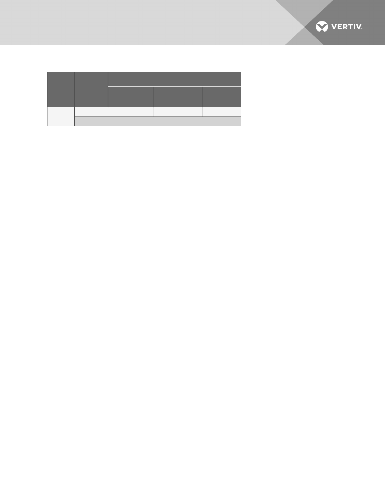
Table 2.2 System configurations—50 Hz
Condensing Unit
Nominal
Capacity
Cooling Unit
Indoor Air-Cooled
Centrifugal Fan
Outdoor Air-Cooled
Propeller Fan
Indoor Remote
Water/Glycol
5 Tons
MMD59E MCD64A PFH066A MCD68W
MMD91C Self-Contained – Chilled Water
Vertiv | Liebert Mini-Mate2—5 ton User Manual| 13

This page intentionally left blank.
Vertiv | Liebert Mini-Mate2—5 ton User Manual| 14

3 INTRODUCTION
3.1 Designed to Match Computer and Electronic Equipment Needs—From
Installation to Operation
Installed above the ceiling, Liebert Mini-Mate2 Precision Cooling systems control the cooling, humidity
and air distribution required by sensitive electronic equipment. A range of sizes and configurations is
available to meet varying sites’ needs.
The Liebert Mini-Mate2 is also easy to use. Advanced microprocessor technology allows easy, precise
control, and menu-driven monitoring keeps you informed of system operation through the LCD readout.
These features, combined with Vertiv™ quality construction and reliable components, guarantee
satisfaction from installation through operation.
Liebert Precision Cooling
Liebert Precision Cooling systems are designed to control the environment required for computers and
other sensitive electronic equipment. The Liebert Mini-Mate2 provides complete control on an aroundthe-clock basis and the high sensible heat ratio required by sensitive electronic equipment.
Easy Installation
The Liebert Mini-Mate2 is a split-system evaporator combined with an air-, water- or glycol-cooled
condensing unit or is a self-contained, chilled water unit. Each split system has thermostat-type wiring to
controls and condensing unit. Optional sweat adapters assist with field refrigerant piping.
Easy to Service
Low-maintenance components are easily accessed through removable front panels. Spare parts are
always in Vertiv™ inventory and available on short notice.
Advanced Control Technology
A menu-driven microprocessor control system provides precise temperature and humidity control and
accurate alarm setpoints. Using touch-sensitive buttons, the wall-mounted monitor/control panel allows
you to select and display temperature and other monitored parameters.
High Efficiency
High sensible heat ratio, scroll compressor and precise microprocessor control allow the system to operate
efficiently.
Space Saving Design
All indoor components are installed above the ceiling, so no floor space is required.
Reliable
The Liebert Mini-Mate2 family installed base is a testimony to the system reliability. Components include a
rugged scroll compressor, high-efficiency copper tube, aluminum-fin evaporator coil and a double inlet,
direct drive fan.
Vertiv | Liebert Mini-Mate2—5 ton User Manual| 15

Agency Listed
Standard 60Hz units are CSA certified to the harmonized U.S. and Canadian product safety
standard, CSA C22.2 No 236/UL 1995 for “Heating and Cooling Equipment” and are marked
with the CSA c-us logo.
Location
When considering installation locations, consider that these units contain water and that water leaks can
cause damage to sensitive equipment below. Do not mount these units above sensitive equipment. A
field-supplied pan with drain must be supplied beneath cooling units and water/glycol condensers.
Do not mount units in areas where normal unit operating sound might disturb the working environment.
Vertiv | Liebert Mini-Mate2—5 ton User Manual| 16

4 STANDARD FEATURES—5 TON SYSTEMS
4.1 Evaporator Section—Split System
The evaporator section is designed for ceiling installation. The cabinet and chassis are constructed of
heavy gauge galvanized steel. The unit can be serviced using only one side increasing its versatility in
mounting locations. Mounting brackets are factory-attached to the cabinet. Internal cabinet insulation
meets ASHRAE 62.1 requirements for Mold Growth, Humidity & Erosion, tested per UL181 & ASTM 1338
standards. The evaporator section includes the evaporator coil, R-407C unit charge, filter-drier, factorymounted disconnect switch, adjustable belt-drive blower assembly and microprocessor control with wallmounted control box. The unit is provided with supply and return air openings for field-supplied ducting.
Evaporators can be configured with canister humidifier and/or reheat. An indoor or outdoor condensing
unit must be selected for each evaporator.
4.2 Condensing Unit Section—Split System
4.2.1 Indoor Centrifugal Fan Condensing Units
Indoor Air-Cooled Centrifugal Fan Condensing Units include scroll compressor, factory-mounted
disconnect switch, condenser coil, R-407C unit charge, belt-driven centrifugal blower assembly,
high-pressure switch, Liebert Lee-Temp™ head pressure control system, hot gas bypass and liquid-line
solenoid valve. Unit must be mounted indoors. Condensing unit is designed to use outdoor air with
temperatures ranging from -30°F to 95°F (-34°Cto35°C).
4.2.2 Outdoor Prop Fan Condensing Units
Outdoor Prop Fan Condensing Units include scroll compressor, condenser coil, R-407C unit charge, prop
fan, liquid-line solenoid valve, high pressure switch, Liebert Lee-Temp head pressure control and hot gas
bypass. Condensing unit is designed for outdoor locations with operating ambients ranging from -30°F to
95°F (-34°Cto35°C).
4.2.3 Indoor Water/Glycol Condensing Units
Indoor Water/Glycol Condensing Units includes scroll compressor, R-407C unit charge, factory-mounted
disconnect, coaxial condenser, hot gas bypass, high head pressure switch and two-way water regulating
valve designed for 150psi (1034.3kPa). Condensing units can be used on either a water or glycol cooling
loop.
4.3 Chilled Water Units
Chilled Water Units are designed for ceiling installation. The cabinet and chassis are constructed of heavy
gauge galvanized steel. The unit can be serviced using only one side increasing its versatility in mounting
locations. Mounting brackets are factory-attached to the cabinet. Internal cabinet insulation meets
ASHRAE 62.1 requirements for Mold Growth, Humidity & Erosion, tested per UL181 & ASTM 1338
standards. Chilled water models are self-contained and include a chilled water coil, belt-driven centrifugal
blower, factory-mounted disconnect switch and two-way, slow-close motorized valve. Design pressure is
300psi (2068kPa), 60psi (414kPa) close-off differential.
Vertiv | Liebert Mini-Mate2—5 ton User Manual| 17
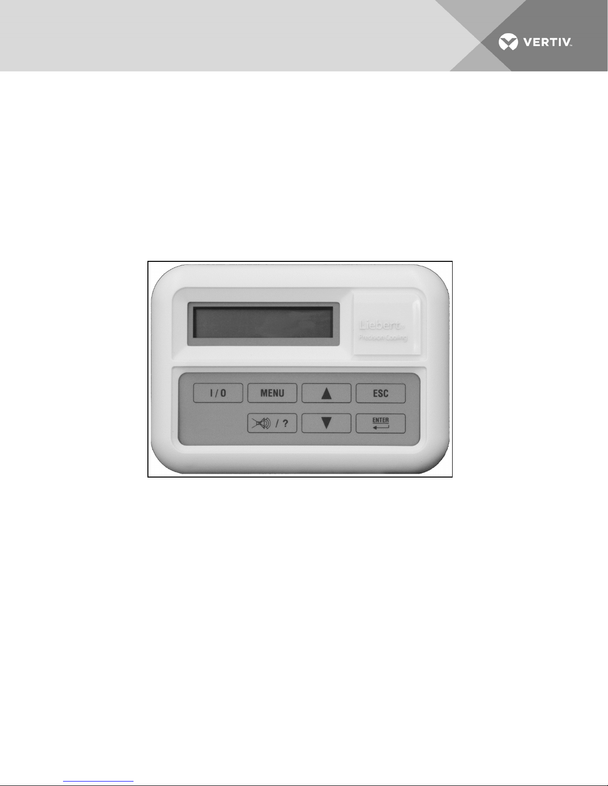
4.4 System Controls
System controls include a microprocessor control board mounted in the evaporator/chilled water unit and
a wall-mounted interface with a two-line, 16-character liquid crystal display. A seven-key, membrane
keypad for setpoint/program control, unit On/Off and alarm silence is below the LCD screen. It provides
temperature setpoint and sensitivity adjustment, humidity setpoint and sensitivity adjustment, digital
display of temperature, humidity, setpoints, sensitivities and alarm conditions.
The wall-box is field-wired to the microprocessor control using standard four-conductor thermostat wire
(field-supplied). The temperature and humidity sensors are in the wall box, which can be installed up to
300 feet (91.4m) from the evaporator unit. The unit-mounted control board also includes common alarm
terminals and shutdown terminals. The unit automatically restarts after a power outage.
Figure 4.1 Wall-box
4.4.1 Other Standard Control Features
• Adjustable auto restart
• 5 day/2 day setback
• Password protection
• Alarm enable/disable
• Self-diagnostics
• Calibrate sensors
• Predictive humidity control
• Common alarm output
• Remote shutdown terminals
Vertiv | Liebert Mini-Mate2—5 ton User Manual| 18

5 OPTIONAL FACTORY-INSTALLED FEATURES EVAPORATOR/CHILLED WATER UNITS
5.1 Reheat
Electric Reheat includes 304/304 stainless steel finned tubular reheat elements, with high limit safety
switch.
SCR Electric Reheat uses an SCR controller and unit control software to provide full cooling with
modulating of the electric reheat elements to control air temperatures. Reheat capacity is up-sized to
offset the cooling capacity. (The SCR Electric Reheat is not available on chilled water, free-cooling or 575V
units.)
Hot Water Reheat includes hot water coil, two-way solenoid valve and Y-strainer.
NOTE: This option is available only on chilled water units, but not with other reheat options.
5.2 Humidifier
The Canister Humidifier includes a steam-generating type humidifier with automatic flushing circuit, inlet
strainer, drain, 1" (25.4mm) air gap on fill line and solenoid valves. Humidifier problem alarm annunciates at
the wall-mounted display panel.
Remote Humidifier Contact allows the unit’s humidity controller to control a humidifier outside the unit.
Power to operate the remote humidifier does not come from the Liebert Mini-Mate2. Available on units
with or without internal humidifier.
5.3 Sensors
Smoke Sensor checks return air, shuts down the unit upon sensing smoke and activates visual and
audible alarms at the wall-box display. This smoke sensor is not intended to function as or replace any
smoke sensor system that may be required by local or national codes.
High-Temperature Sensor senses the return air temperature and shuts down unit if the temperature
reaches 125°F (52°C). This device is not meant to replace any fire detection system that may be required
by local or national codes.
5.4 Switches and Motors
Filter Clog senses pressure drop across the filters and activates visual and audible alarms at the wall-box
display. The wall-box display annunciates the alarm audibly and flashes a notification upon reaching a
customer setpoint.
A Factory-Installed Non-Fused Disconnect Switch allows unit to be turned off for maintenance. A
disconnect switch is standard for the evaporators, chilled water units and indoor condensing units, but
these units may be specified without the switch.
2hp Blower Motor is available for high static applications (0.9 to 1.5 in. [23 to 38 mm] w.g.).
Vertiv | Liebert Mini-Mate2—5 ton User Manual| 19
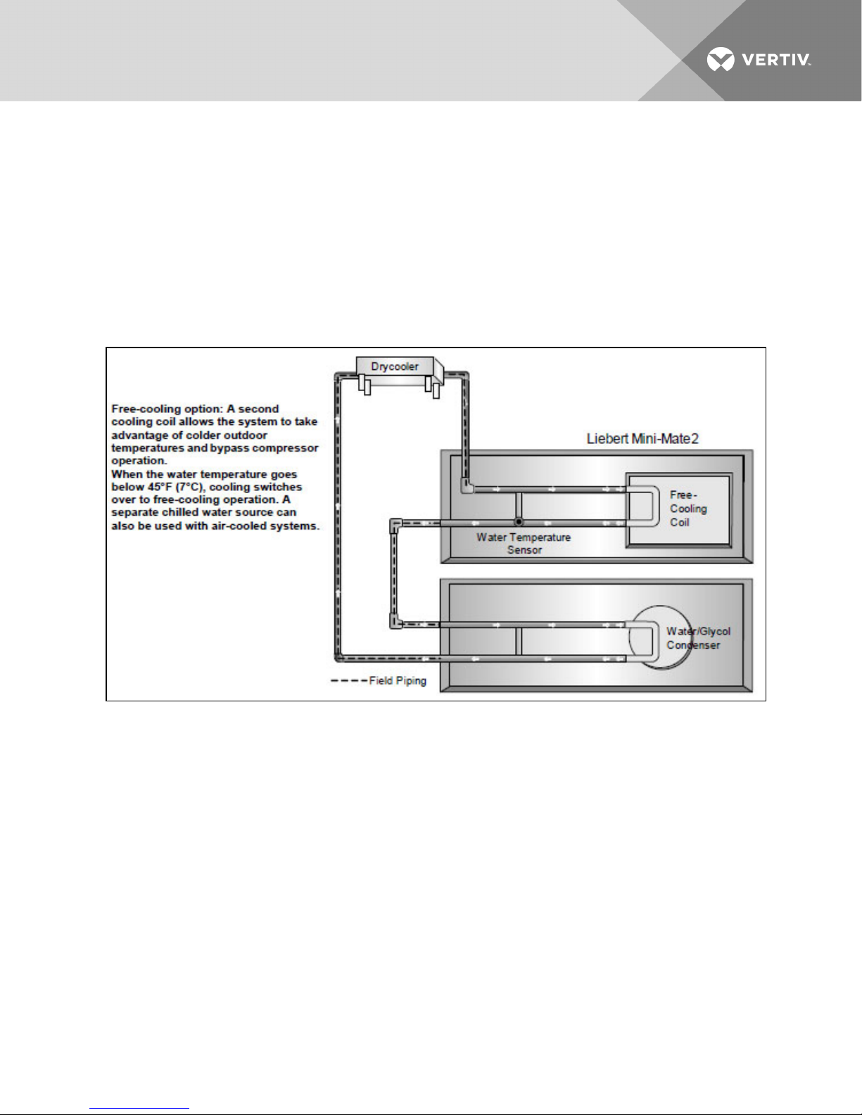
5.5 Free-Cooling
Free-cooling option includes separate cooling coil, three-way slow-close valve and separate supply and
return piping. Free-cooling is activated when the water temperature reaches a field-adjustable
temperature, typically 45°F (7°C). The valve is rated for 300psi (2068kPa) working pressure.
Air-cooled condensing units can be matched with evaporators using free-cooling coils with chilled water
sources to serve as backup cooling. When matched with a water/glycol condensing unit, a three-way
water regulating valve is recommended for the condensing unit to simplify piping to the main supply
pipes. The coil is designed for closed-loop applications using properly treated and circulated fluid. Not
available with SCR reheat options.
Figure 5.1 Free-cooling arrangement
NOTE: If free-cooling is applied to an open water tower, an optional copper-nickel (CuNi) coil is
required to prevent premature corrosion, or a heat exchanger must separate the tower water from the
free-cooling loop. The copper-nickel coil requires an extended lead time.
5.6 Optional Configurations—Prop Fan Condensing Units
Outdoor Prop Fan Condensing Units are also available in the following optional configurations:
• High ambient, top discharge models for catalog capacities at ambient temperatures up to
105°F (40°C).
• Quiet-Line models for low noise level conditions (below 56 dBA) and catalog capacities for
ambient temperatures up to 95°F (35°C).
• Condenser coil(s) can be phenolic-coated for extended coil life in coastal areas.
Vertiv | Liebert Mini-Mate2—5 ton User Manual| 20

5.7 Optional Configurations—Water/Glycol Condensing Units
Indoor Water/Glycol Condensing Units are also available with the following piping options:
• Two-way water reg. valve with 350 psi (2413kPa) design pressure.
• Three-way water reg. valve with 150psi (1034kPa) design pressure.
• Three-way water reg. valve with 350psi (2413kPa) design pressure.
5.8 Optional Configurations—Chilled Water Units
Chilled Water Units are also available with the following valve options:
• Three-way, slow-close, motorized chilled water valve rated for 300psi (2068kPa) working
pressure. Valve is non-spring return.
• Two-way modulating chilled water valve, rated for 400psi (2758kPa) operating pressure, 72psi
(496kPa) close-off rating. Valve is non-spring return.
• Three-way modulating chilled water valve, rated for 400psi (2758kPa) operating pressure.
Valve is non-spring return.
Vertiv | Liebert Mini-Mate2—5 ton User Manual| 21

This page intentionally left blank.
Vertiv | Liebert Mini-Mate2—5 ton User Manual| 22

6 SHIP-LOOSE ACCESSORIES—FIELD-INSTALLED
Filter Box includes filter box with 1" (25.4mm) duct flange connection, quantity 2, 20" x 20" x 4" nominal
(508mm x 508mm x 102mm) filters and a 1" (25.4mm) duct flange for use on the supply air opening. Filters
are MERV 8 efficiency per ASHRAE Standard 52.2-2007.
Condensate Pump is equipped with a discharge check valve. The pump is supplied with a mounting
bracket for field-mounting onto ductwork and can be field-wired to the unit power block. A secondary
float can be field-wired to shut down the unit upon high condensate level.
Condensate Pump Mounting Bracket is available for a mounting condensate pump on the end of the unit
instead of on the duct work for easy alignment and installation of the condensate pump.
Remote Temperature and Humidity Sensors include sensors mounted in an attractive case with 30 ft.
(9m) of cable. Installing the remote temperature and humidity sensor module disable the temperature
and humidity sensors mounted in the wall box.
Field-installed kits are available for filter clog, smoke sensor, high temperature sensor, electric reheat and
humidifier. The kits include installation instructions and are designed to be added to the evaporator unit
before it is installed in the ceiling. Electric reheat kits cannot be installed in units with free-cooling.
Refrigerant-line sweat adapter kit contains two suction and two liquid-line compatible fittings that allow
use of field-supplied, interconnecting refrigerant lines.
Single Point Power Kit contains the necessary electrical components to interconnect the high voltage
sections of a close-coupled evaporator and indoor condensing unit.
6.1 Remote Monitoring, Autochangeover and Leak Detection Equipment
The Liebert RCM4™ is a four-point, normally open, dry contact monitoring panel. One Form-C, dry
contact common alarm relay output (rated at 24VAC, 3A) is provided. Four red LEDs illuminate on the
respective alarm and the alarm buzzer is silenced by a front panel switch. The RCM4 requires a 24VAC or
24VDC power source. Power supply is not included.
The Liebert AC4™ Autochangeover Controller provides autochangeover and autosequence control for
up to four Liebert Mini-Mate2 units within a room. The Liebert AC4 will enable redundant units in an
alarm condition, balance usage and test standby units at programmed intervals. Two common alarm relay
outputs are available. A built-in LCD and RS-232 port for direct PC/terminal connection provides two
options for configuration and monitoring of the product. The Liebert AC4 requires 24VAC input power.
The Liebert AC8™ is ideal for coordinated control of systems with redundant units. The Liebert AC8
enables redundant devices during an alarm condition, balances usage of devices and tests standby
devices at programmable intervals. Supports four zones and can use the 4-20mA temperature sensor
(TW420) for temperature staging in each zone. Two programmable output control relays are available for
auxiliary control such as humidity lockout. Emergency power operation input provided for device control
during an emergency. Two common alarm relay outputs are available. A built-in LCD and RS-232 port for
direct PC/terminal connection provides two options for configuration and monitoring of the product.
The Liebert ENV-DO™ interface card provides 16 discrete outputs, corresponding to status and major
alarm conditions of Environmental units. The Liebert ENV-DO-ENCL1 packages one Environmental DO
interface card in its own steel enclosure and the ENV-DO-ENCL2 packages two Environmental DO
interface cards in one enclosure for installation external to the Liebert Mini-Mate2. The self-contained kit
includes an external 120VAC-to-24VAC power transformer. Wiring harnesses are not provided. Power and
communication wiring is field-provided.
Vertiv | Liebert Mini-Mate2—5 ton User Manual| 23

The Liebert Liqui-tect® 410 Point Leak Detection Sensor detects the presence of conductive liquid using
a pair of corrosion-resistant, gold-plated probes mounted in a painted, height-adjustable enclosure. Dual
Form-C, dry contact common alarm relays (rated at 24VAC, 3A) signal a leak detected as well as loss of
power and cable fault. The Liebert Liqui-tect 410 requires an external 24VAC or 24VDC power source.
Liebert LT460 Zone Leak Detection Kits include one LT460 sensor, a specified length of LT500-xxY
cable (maximum length is 100 ft [30.5m]) and a corresponding number of hold-down clips. The Liebert
LT460 requires an external 24VAC, 0.12A power source, such as EXT-XFMR or XFMR24.
Liebert SiteScan®is a monitoring solution that gives you decision-making power to effectively manage
the equipment critical to your business.
Liebert SiteScan enables communication from Liebert Precision Cooling and Power Protection units, as
well as many other pieces of analog or digital equipment, to a front-end software package that provides
real-time status and alarms so you can react quickly to changing situations.
Liebert SiteScan is designed with flexibility for both small systems and large, complex systems such as
those in computer rooms, telecommunications facilities or industrial process control rooms. Contact your
local Vertiv™ representative for assistance with a Liebert SiteScan system.
The NIC-ENCL1 and NIC-ENCL2 package one or two Liebert IntelliSlot® Web/485 Cards with Adapters,
respectively, in one steel enclosure for installation external to the Liebert Mini-Mate2. The Liebert
IntelliSlot Web/485 Card with Adapter provides communication with the Liebert Mini-Mate2™ via SNMP,
HTTP, RTU Modbus 485 and BACnet IP. The self-contained kit includes an external 120VAC-to-24VAC
transformer as a power source. Wiring harnesses are not provided. Power and communication wiring are
field-provided.
Vertiv | Liebert Mini-Mate2—5 ton User Manual| 24
7 SITE PREPARATION AND INSTALLATION
NOTE: Before installing unit, determine whether any building alterations are required to run piping,
wiring and duct work. Carefully follow all unit dimensional drawings and refer to the submittal
engineering dimensional drawings of individual units for proper clearances.
7.1 Installation Considerations
The evaporator unit is usually mounted above the suspended ceiling in the space to be conditioned.
Ducted systems may be located in a different room. Refer to Figure 7.1 on the next page and Figure 7.2
on page27 for possible configurations. The condensing unit may be:
• Indoor Air-Cooled Centrifugal Fan Condensing Unit mounted remotely or close coupled to the
evaporator in the ceiling space.
• Outdoor Air-Cooled Propeller Fan Condensing Unit.
• Water/Glycol Cooled Condensing Unit, mounted remotely or close coupled to the evaporator.
Table 7.1 Application limits, evaporator and chilled water
units*
Input Voltage Range of Return Air Conditions to Unit
Min Max Dry Bulb Temperature Relati ve Humidity
-5% +10%
*Unit will operate at these conditions but will not control to these extremes.
65°F to 85°F
(18°Cto 29°C)
20% to 80%
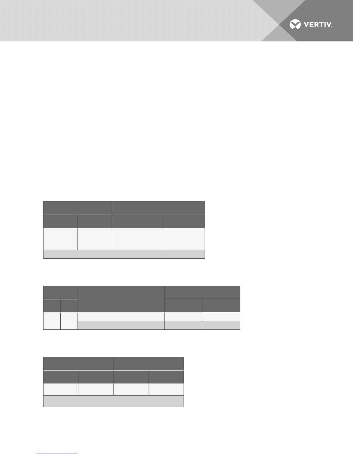
Table 7.2 Application limits, indoor and outdoor air-cooled condensing
units
Input Voltage
Condensing Units
Min Max Mi n Max
-5% +10%
Outdoor Prop Fan Condensing Unit -30°F (-34 °C) 120°F ( 49°C)
Indoor A ir-Cooled Centrifugal Condensing Unit -20°F ( -29°C) 115°F (46°C)
Entering Dry Bulb Air Temperature
Table 7.3 Application limits, indoor water/glycol
cooled condensing units
Input Voltage Entering Fluid Temperat ure
Min Max Min Max
-5% +10%
65°F (18.3°C) * 115°F (46°C)
*Operation below 65°F (1 8°C) may result in reducedvalve life and fluid noise.
Vertiv | Liebert Mini-Mate2—5 ton User Manual| 25
7.1.1 Room Preparation
The room should be well insulated and must have a sealed vapor barrier. The vapor barrier in the ceiling
and walls can be a polyethylene film. Paint on concrete walls and floors should contain either rubber or
plastic.
NOTE: The single most important requirement for maintaining environmental control in the
conditioned room is the vapor barrier.
Outside or fresh air should be kept to a minimum when tight temperature and humidity control is
required. Outside air adds to the cooling, heating, dehumidifying and humidifying loads of the site. Doors
should be properly sealed to minimize leaks and should not contain ventilation grilles.
7.1.2 Location Considerations
CAUTION: Risk of leaking water/glycol. Can cause equipment, furniture and building damage.
Do not mount units over equipment or furniture that can be damaged by leaking water /glycol.
Install a watertight drain pan with a drain connection under the cooling unit and ceiling
mounted water-cooled condensing unit. Route the drain line to a frequently used maintenance
sink so that running water can be observed and reported in a timely manner. Post a sign to alert
people to report water flowing from the secondary drain pan.
NOTE: Do NOT mount units in areas where normal unit operating sound may disturb the working
environment.
Locate the evaporator unit over an unobstructed floor space if possible. This will allow easy access for
routine maintenance or service. Do not attach additional devices (such as smoke detectors, etc.) to the
housing, as they could interfere with the maintenance or service.
NOTE: Temperature and humidity sensors are located in the wall box. Carefully select a position for the
box where discharge air DOES NOT blow directly on the sensors.
Figure 7.1 Air-cooled systems
Vertiv | Liebert Mini-Mate2—5 ton User Manual| 26
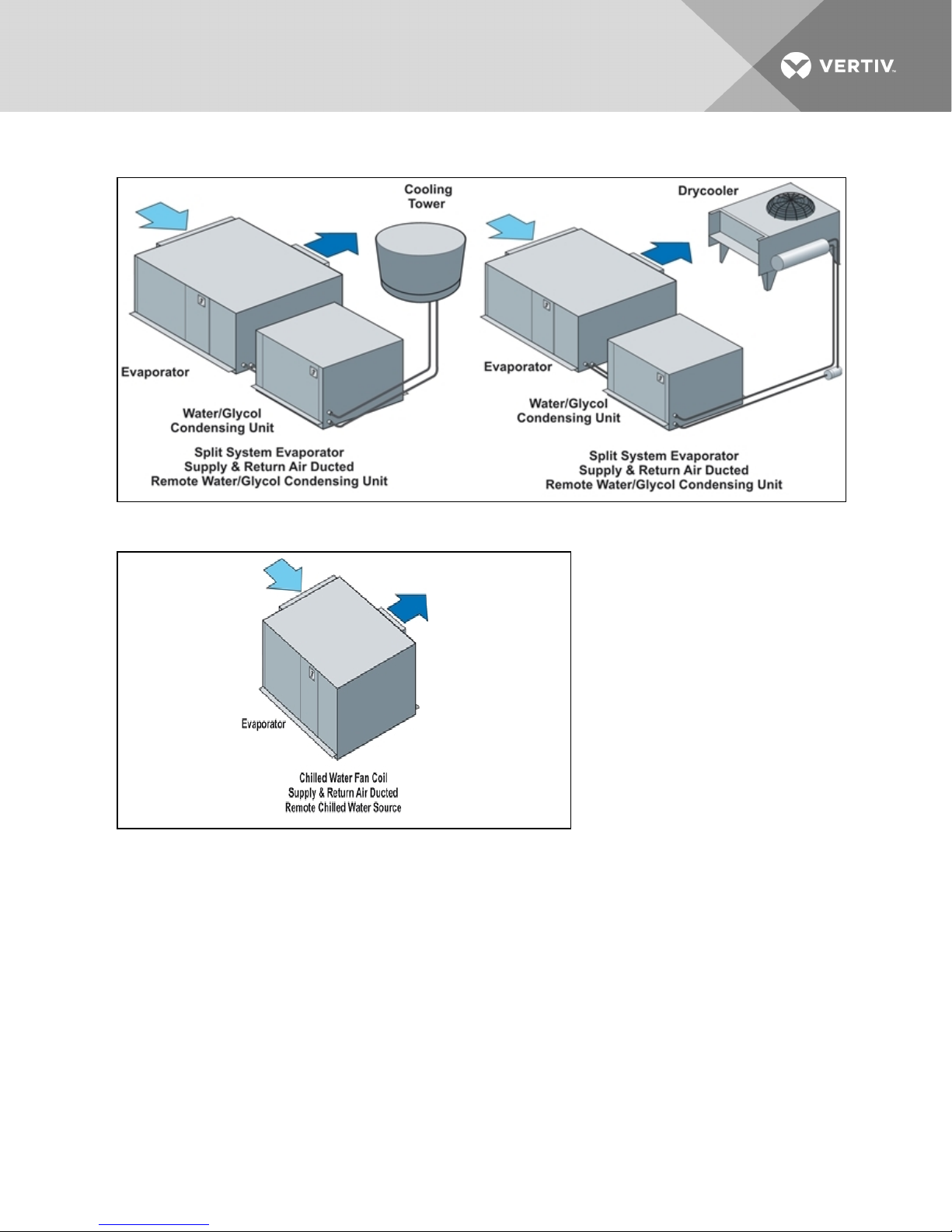
Figure 7.2 Water/glycol cooled systems
Figure 7.3 Chilled water systems
Vertiv | Liebert Mini-Mate2—5 ton User Manual| 27
7.2 Ceiling Unit Weights
Table 7.4 Unit weights
Cooling Units * lb. kg
MMD60E 498 226
MMD59E 498 226
MMD92C 498 226
MMD91C 4 98 226
CondensingUnits lb. kg.
MCD65A 4 49 204
MCD64A 44 9 204
MCD69W 282 128
MCD68W 282 128
*Add 32 lb. (14 kg.) tounits with free cooling or hot water reheat coils.
7.3 Equipment Inspection Upon Receipt
When the unit arrives, do not uncrate equipment until it is close to its final location. All required
assemblies are banded and shipped in corrugated containers. If you discover any damage when you
uncrate the unit, report it to the shipper immediately. If you later find any concealed damage, report it to
the shipper and to your Liebert supplier.
7.4 Installing the Ceiling Units
WARNING! Risk of ceiling collapse and heavy unit falling. Can cause building damage, serious
injury or death. Verify that the supporting roof structure is capable of supporting the weight of
the unit(s) and the accessories during installation and service. (See Ceiling Unit Weights
above.) Securely anchor the top ends of the suspension rods and verify that all nuts are tight.
The evaporator unit and indoor condensing unit are usually mounted above the ceiling and must be
securely mounted to the roof structure. The ceiling and ceiling supports of existing buildings may require
reinforcements. Be sure to follow all applicable national and local building codes. Use field-supplied
threaded suspension rods and 3/8"–16 factory hardware kit.
Recommended clearance between ceiling grids and building structural members is unit height plus three
inches (76.2mm).
Install the four field-supplied rods by suspending them from suitable building structural members. Locate
the rods so that they will align with the four mounting holes in the flanges that are part of the unit base.
Using a suitable lifting device that is rated for the weight of the unit (see Ceiling Unit Weights above),
raise the unit up and pass the threaded rods through the four mounting holes in the flanges that are part
of the unit base.
Vertiv | Liebert Mini-Mate2—5 ton User Manual| 28
 Loading...