

Vertiv Liebert MCV Series, Liebert MCV330, Liebert MCV440, Liebert MC Installer/user Manual

Liebert® MCV™
60-Hz, High-density Microchannel Condenser
Installer/User Guide

Technical Support Site
If you encounter any installation or operational issues with your product, check the pertinent section of
this manual to see if the issue can be resolved by following outlined procedures. For additional assistance,
visit https://www.VertivCo.com/en-us/support/.

TABLE OF CONTENTS
1 Important Safety Instructions 5
2 Nomenclature and Components 7
2.1 Liebert MCV Model-number Nomenclature 7
2.2 Component Location 8
2.3 Product Description and Features 9
2.4 Control, Fan Types and Features 9
2.4.1 Premium Efficiency Control/EC Fan 9
2.4.2 Anti-Freezing Operation 9
2.4.3 Surge Protective Device 10
3 Pre-installation PreparationandGuidelines 11
3.1 Planning Dimensions 11
3.2 Unit Weights 11
4 Equipment Inspection and Handling 13
4.1 Packaging Material 13
4.2 Remove Shipping Panels and Brackets 14
5 Piping 15
5.1 Refrigerant Piping and Charging 15
5.1.1 Refrigerant Piping Guidelines forAir-cooledSystems 16
5.1.2 Additional Oil Requirements 17
5.2 System Dehydration/Leak Test 17
5.3 Charging Condensers with DSE Receivers 17
6 Electrical Connections 19
6.1 Line Voltage Wiring 20
6.1.1 Acceptable Power Supplies—380V to 460V Nominal Units 21
6.1.2 Unacceptable Power Supplies 21
7 Checklist for Completed Installation 23
7.1 Moving and Placing Equipment 23
7.2 Electrical Installation Checks 23
7.3 Piping Installation Checks 23
7.4 Other Installation Checks 23
8 Initial Start-up Checks andCommissioningProcedure forWarrantyInspection 24
9 Troubleshooting 25
10 Control Operation 27
10.1 Premium Efficiency Control Board and Interface 27
10.1.1 Initial Display upon Power-On 29
10.1.2 Navigating the Controller-interface Main Menu 29
10.1.3 Analog Signals Menu 30
10.1.4 Active Alarms Menu 31
10.1.5 History Alarms Menu 32
11 Maintenance 35
Vertiv | Liebert® MCV™ Installer/User Guide | 3
11.1 General Condenser Maintenance 36
11.2 Condenser Cleaning 36
11.2.1 When to Clean the Condenser Coil 36
11.2.2 What to Use to Clean the Condenser Coil 36
11.2.3 Cleaning the Condenser Coil 37
11.3 Replacing the Condenser Fan 37
11.3.1 Verifing the Fan Address 43
11.4 Replacing the Premium-efficiency Control Board 47
11.4.1 Preparing to Replace the Board 47
11.4.2 Installing the Replacement Board 48
12 Preventive Maintenance Checklist 50
Appendices 55
Appendix A: Technical Support and Contacts 55
Appendix B: Submittal Drawings 57
Vertiv | Liebert® MCV™ Installer/User Guide | 4
1 IMPORTANT SAFETY INSTRUCTIONS
SAVE THESE INSTRUCTIONS
This manual contains important safety instructions that should be followed during the installation and
maintenance of the LiebertMCV. Read this manual thoroughly before attempting to install or operate this
unit.
Only qualified personnel should move, install or service this equipment.
Adhere to all warnings, cautions, notices and installation, operating and safety instructions on the unit
and in this manual. Follow all installation, operation and maintenance instructions and all applicable
national and local building, electrical and plumbing codes.
WARNING! Arc flash and electric shock hazard. Open all local and remote electric power-supply
disconnect switches, verify with a voltmeter that power is Off and wear appropriate,
OSHA-approved personal protective equipment (PPE) per NFPA 70E before working within the
electric control enclosure. Failure to comply can cause serious injury or death. Customer must
provide earth ground to unit, per NEC, CEC and local codes, as applicable. Before proceeding
with installation, read all instructions, verify that all the parts are included and check the
nameplate to be sure the voltage matches available utility power. The Liebert controller does
not isolate power from the unit, even in the “Unit Off” mode. Some internal components require
and receive power even during the “Unit Off” mode of the controller. The only way to ensure
that there is NO voltage inside the unit is to install and open a remote disconnect switch. Refer
to unit electrical schematic. Follow all local codes.
WARNING! Risk of over-pressurization of the refrigeration system. Can cause explosive
discharge of high-pressure refrigerant, loss of refrigerant, environmental pollution, equipment
damage, injury, or death. This unit contains fluids and gases under high pressure. Use extreme
caution when charging the refrigerant system. Do not pressurize the system higher than the
design pressure marked on the unit's nameplate.
WARNING! Risk of contact with high-speed, rotating fan impeller blades. Can cause injury or
death. Open all local and remote electric power-supply disconnect switches, verify with a
voltmeter that power is off, and verify that all fan impellers have stopped rotating before
working in the unit cabinet.
WARNING! Risk of contact with high-speed rotating fan blades. Can cause serious injury or
death. If control voltage is applied, the fan motor can restart without warning after a power
failure. Open all local and remote electric power-supply disconnect switches, verify with a
voltmeter that power is off, and verify that all fan blades have stopped rotating before working
on the fan assembly. After working on the fan assembly, remove any used tools or other
objects from the unit cabinet before restoring electric power.
Vertiv | Liebert® MCV™ Installer/User Guide | 5

WARNING! Risk of improper wiring, piping, moving, lifting and handling. Can cause equipment
damage, serious injury or death. Installation and service of this equipment should be done only
by qualified personnel, wearing appropriate, OSHA-approved PPE, who have been speciallytrained in the installation of air-conditioning equipment.
WARNING! Risk of improper wire and loose electrical connections. Can cause overheated wire
and electrical connection terminals resulting in smoke, fire, equipment and building damage,
injury or death. Use correctly sized copper wire only and verify that all electrical connections are
tight before turning power On. Check all electrical connections periodically and tighten as
necessary.
CAUTION: Risk of contact with sharp edges, splinters, and exposed fasteners. Can cause
injury. Only properly trained and qualified personnel wearing appropriate, OSHA-approved PPE
should attempt to move, lift, remove packaging from or prepare the unit for installation.
CAUTION: Risk of improper moving, lifting and handling. Can cause equipment damage or
injury. Only properly trained and qualified personnel should work on this equipment. Fan
modules weigh in excess of 115lb(52.2kg). Use proper lifting techniques and wear appropriate,
OSHA-approved PPE to avoid injury and dropping the fan module during removal. Equipment
used in handling/lifting, and/or installing the fan assembly must meet OSHA requirements. Use
handling/lifting equipment rated for the weight of the fan assembly. Use ladders rated for the
weight of the fan assembly and technicians if used during installation. Refer to handling/lifting,
and/or installation equipment operating manual for manufacturer's safety requirements and
operating procedures.
CAUTION: Risk of exposure to harmful noise levels. Can cause hearing injury or loss.
Depending on the installation and operating conditions, a sound pressure level greater than
70dB(A) may arise. Take appropriate technical safety measures. Operating personnel must
wear appropriate, OSHA-approved PPE and observe all appropriate hearing-protection safety
requirements.
NOTICE
Risk of oil contamination with water. Can cause equipment damage.
LiebertMCV systems require the use of POE (polyolester) oil. POE oil absorbs water at a much
faster rate when exposed to air than previously used oils. Because water is the enemy of a
reliable refrigeration system, extreme care must be used when opening systems during
installation or service. If water is absorbed into the POE oil, it will not be easily removed and will
not be removed through the normal evacuation process. If the oil is too wet, it may require an oil
change. POE oils also have a property that makes them act as a solvent in a refrigeration
system. Maintaining system cleanliness is extremely important because the oil will tend to
bring any foreign matter back to the compressor.
Vertiv | Liebert® MCV™ Installer/User Guide | 6
2 NOMENCLATURE AND COMPONENTS
This section describes the model-number configuration for Liebert MCV units and components.
2.1 Liebert MCV Model-number Nomenclature
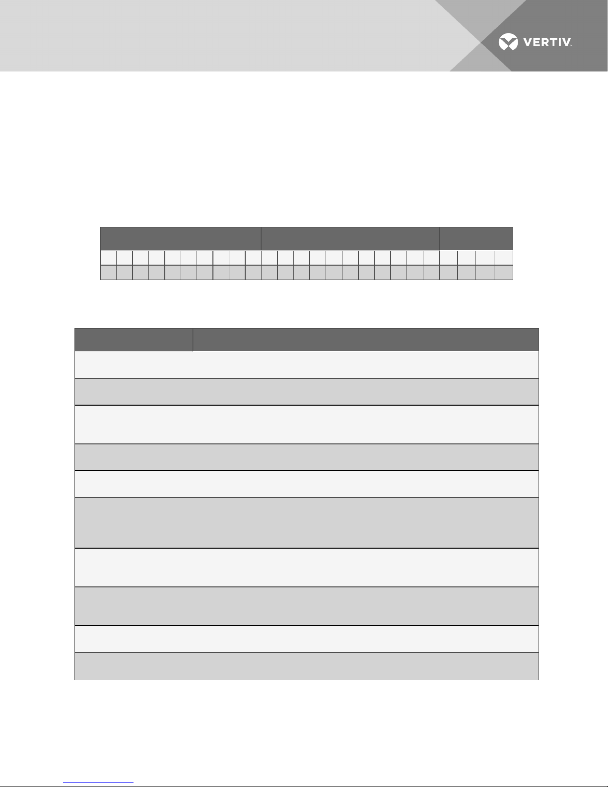
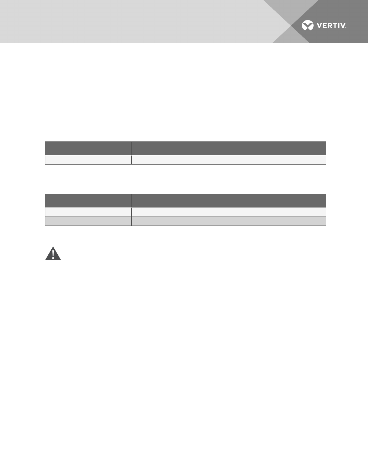
Table 2.2 below describes each digit of the 25-digitconfigurationnumber. The 14-digit model number
consists of the first 10 digits and last four digits of the configuration number.
Table 2.1 Liebert MCV 25-digit Configuration Number Example
Model # Part 1 Model Details Model # Part 2
1 2 3 4 5 6 7 8 9 10 11 12 13 14 15 16 17 18 19 20 21 22 23 24 25
M C V 3 3 0 E 2 A D 0 G 0 0 U 0 2 0 0 0 0 * * * *
Table 2.2 MCV Model-number Digit Definitions
Digit Description
Digits 1 and2 = Unit Family
MC = MicrochannelCondenser
Digit3 Platform Size
V = V-coil arr angement
Digits 3-6 - Nominal Capacity, kW
330 = 330kW
440 = 440kW
Digit7 - Control/Fan Type
E = Pr emium control and E C fan
Digit8 - Refrigerant Circuits/System Refrigerant Type
2 = Dual refrigerant circuit, R-410A
Digit9 - Power Supply
A = 4 60V / 3ph / 60Hz
2 = 380V / 3ph / 60Hz
M = 380-415V / 3ph / 50Hz
Digit10 - Packaging
D = Domestic, non-stackable
E = Export crating, non-stackable
Digit11 - Coil Coating
0 = None
E = E-coat (epoxy)
Digit12 - PanelMaterial
G = Galvanizedsteel
Digit13 - ConnectionPipe Unit of Measurement
0 = Inches (std. ACR copper)
Vertiv | Liebert® MCV™ Installer/User Guide | 7
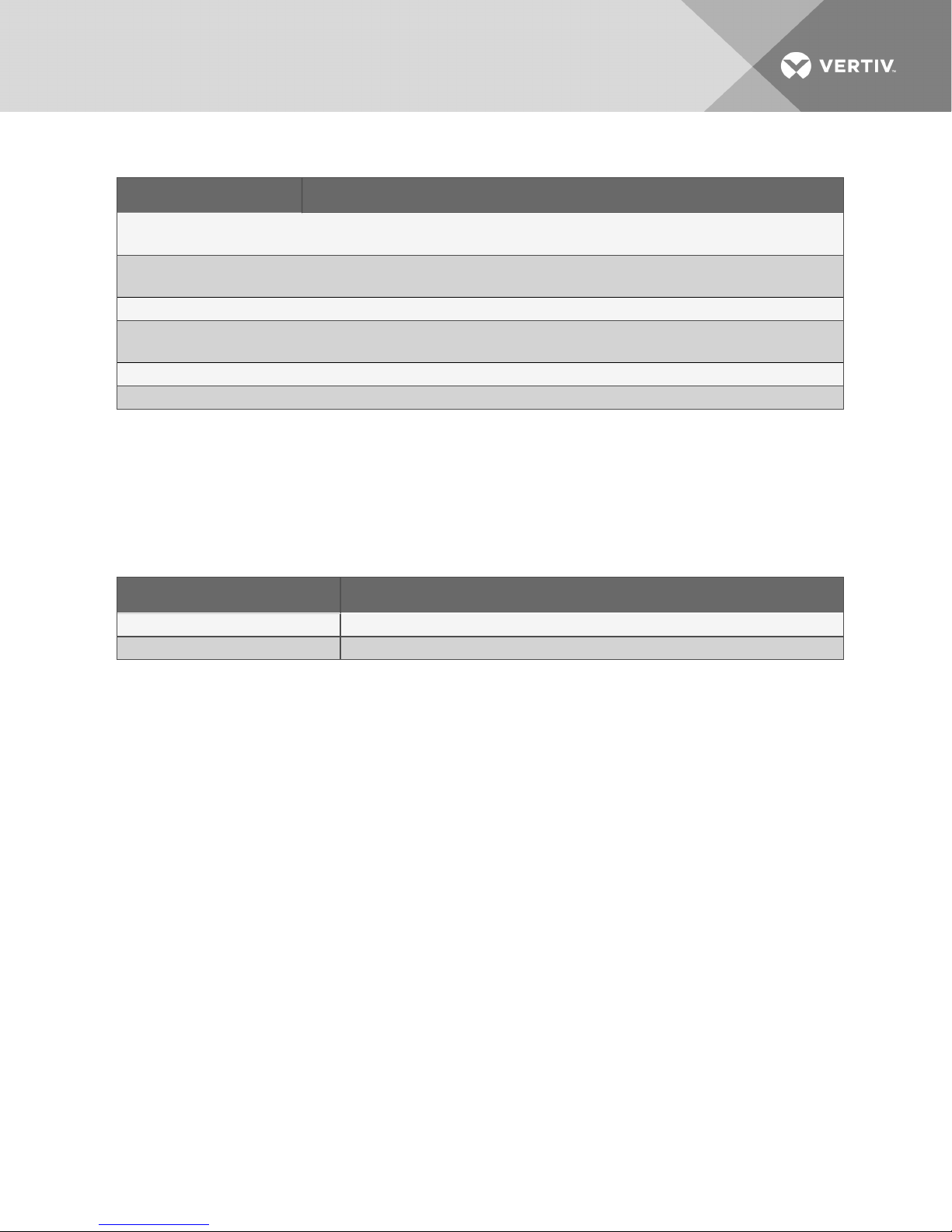
Table 2.2 MCV Model-number Digit Definitions (continued)
Digit Description
Digit14 - Legs Included
0 = No legs (standard)
Digit15 - Agency Certification
U = CSA listed, mar ked withCSA c-us logo
Digit16 - Undefined, Reserved for future use.
Digit17 - Receiver/Software Configuration
2 = Liebert DSEsoftware
Digits 18-21 - Undefined, Reser ved for future use.
Digits 22-25 - Factory Configuration Number
2.2 Component Location
The unit component locations are described in the submittal documents included in the Submittal
Drawings on page57.
The following table lists the relevant documents by number and title.
Table 2.3 Component-location Drawings
Document Number Titl e
DPN003871 ComponentL ocations, 6-fan MCV330
DPN004210 ComponentL ocation, 8-fan MCV440
Vertiv | Liebert® MCV™ Installer/User Guide | 8
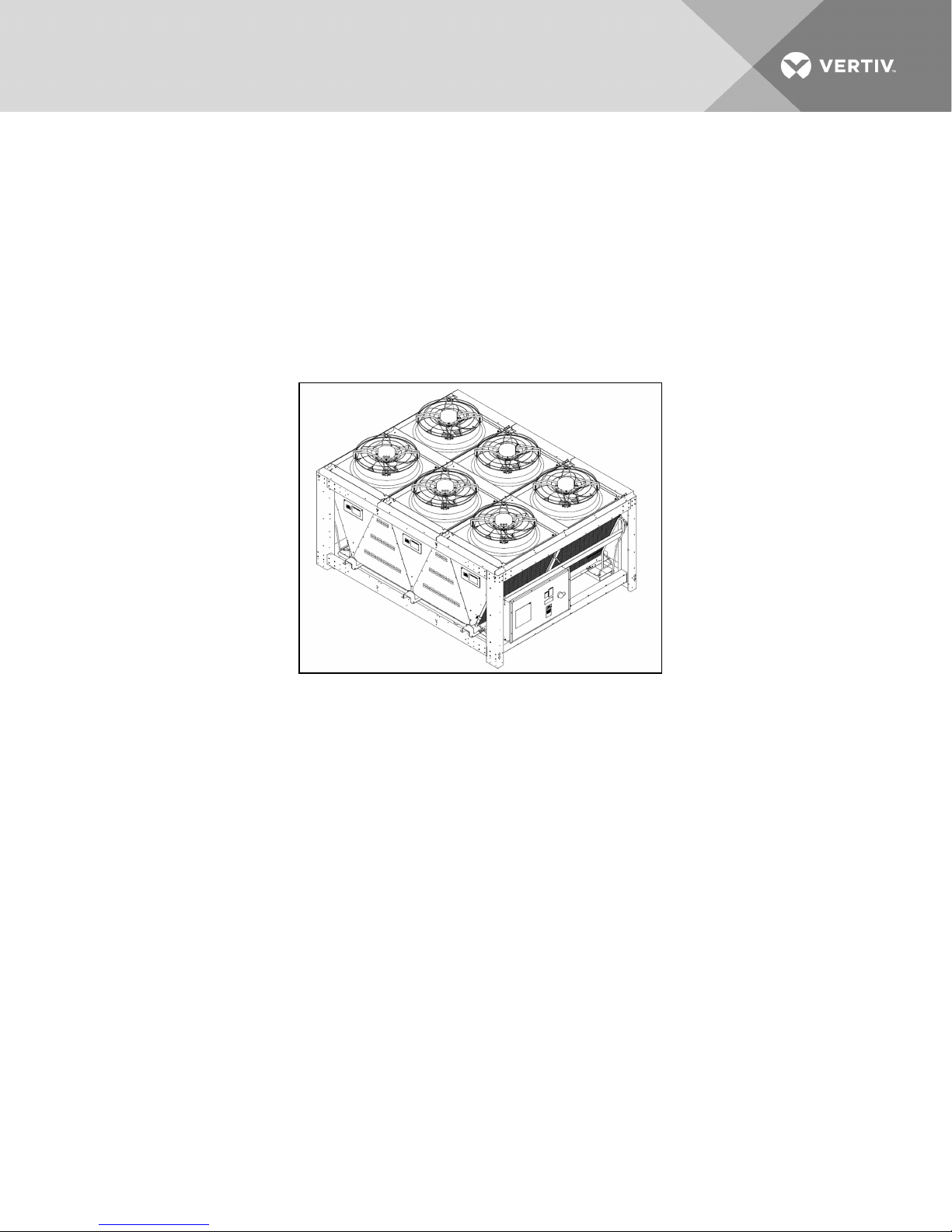
2.3 Product Description and Features
The Liebert MCV condenser is a direct-drive EC-fan type air-cooled heat-rejection unit suitable for
mounting outdoors. It provides heat rejection for two separate refrigeration circuits, matches the heat
rejection capacity corresponding with the outdoor ambient temperature and with each corresponding
compressor heat-rejection requirements. Constructed with a galvanized-steel frame, galvanized-steel
panels and aluminum microchannel coil, the unit is quiet and corrosion resistant. The condenser is quickly
and easily installed, because all internal wiring is completed at the factory with only electrical connections
to be made at the job site. All electrical connections and controls are enclosed in an integral, weatherproof
section of the condenser.
Figure 2.1 Liebert MCV
2.4 Control, Fan Types and Features
2.4.1 Premium Efficiency Control/EC Fan
Premium Efficiency Controls and EC fans are matched to provide superior system energy efficiency. The
premium control board allows CANbus communication with the indoor unit’s Liebert iCOM™ control. This
communication feature provides compressor run signals, condenser operating mode changes, condenser
alarm monitoring, simplified system charging procedures and outdoor temperature monitoring.
The Premium Efficiency Control board on a Liebert MCV maintains EC fans on the same circuit to the
same speed in order to maintain refrigerant head pressure in DX mode and refrigerant temperature in
EconoPhase mode.
2.4.2 Anti-Freezing Operation
The EC fans must be operated periodically in cold weather to reduce the possibility of lockup due to ice
and snow accumulation. During periods of fan inactivity and outdoor temperatures below 35°F (1.6°C), the
EC fans will spin for at least 30 seconds every 15 minutes at 60% of the maximum fan speed.
Vertiv | Liebert® MCV™ Installer/User Guide | 9

2.4.3 Surge Protective Device
An optional Surge Protective Device (SPD) can be field-wired to protect the condenser from power surges
that threaten sensitive equipment. The condenser’s electrical panel provides a terminal block to allow the
SPD to be wired in parallel with the high-voltage power. An additional low-voltage terminal block is
provided on condensers to allow monitoring of the SPD alarm circuit.
ASCO Series 420 surge-protective device provides 50kA per mode of surge current protection. An
illuminated green LED indicates the SPD is On and operating properly. An illuminated red LED indicates
that the device may require replacement.
When both LEDs are Off, there is no power to the condenser, either from a power failure or because the
condenser disconnect is in the Off position.
Vertiv | Liebert® MCV™ Installer/User Guide | 10
3 PRE-INSTALLATION PREPARATIONANDGUIDELINES
The unit dimensions, pipe-connection locations, and piping schematics are described in the submittal
documents included in the Submittal Drawings on page57.
• Install the condenser in a location offering maximum security and access for maintenance.
• Avoid ground-level sites with public access and areas prone to heavy snow or ice
accumulations.
• To ensure adequate air supply, we recommend that condensers be installed in an area with
clean air, away from loose dirt and foreign matter that might clog the coil. In addition,
condensers should be located no closer than 3 ft (1m) from a wall, obstruction or adjacent unit.
• For roof installation, mount the condenser on suitable curbs or other supports in accordance
with local codes.
• Condensers must not be installed in a pit.
• Condensers must be installed on a level surface to ensure proper refrigerant flow.
• Condensers must not be installed below the indoor unit.
• Condensers must be installed in vertical airflow orientation to maintain the electrical box’s
NEMA 3R rating.
3.1 Planning Dimensions
The unit, floor stand, and plenum dimensions are described in the submittal documents included in the
Submittal Drawings on page57.
The following table lists the relevant documents by number and title.
Table 3.1 Dimension Planning Drawings
Document Number Titl e
DPN003874 Cabinet and Floor PlanningDimensional Data, MCV330
DPN004209 Cabinet and Floor Planning DimensionalData, MCV440
3.2 Unit Weights
Table 3.2 MCV Skid Approximate Weights
Model
MCV330 6 1 4,800 (2,177)
MCV330 6 2 10,000 (4,536)
MCV440 8 1 5,365 (2,433)
MCV440 8 2 10,730 (4 ,867)
Number of Fans
on Condenser
Number of Units
on Skid
Weight, lb(kg)
Vertiv | Liebert® MCV™ Installer/User Guide | 11

This page intentionally left blank.
Vertiv | Liebert® MCV™ Installer/User Guide | 12
4 EQUIPMENT INSPECTION AND HANDLING
SAFETY INFORMATION
WARNING! Risk of improperly moving, lifting, or handling. Improper handling can cause
equipment damage, injury or death. Read all of the following instructions and verify that all
lifting and moving equipment is rated for the weight of the unit before attempting to move, lift,
remove packaging from or prepare the unit for installation.
CAUTION: Risk of contact with sharp edges, splinters, and exposed fasteners. Can cause
injury. Only properly trained and qualified personnel wearing appropriate, OSHA-approved PPE
should attempt to move, lift, remove packaging from or prepare the unit for installation.
NOTICE
Risk of improper lifting. Can cause equipment damage. Make sure that the spreader bars wider
are than the unit. If the spreader bars are too short, the slings may crush the unit.
NOTICE
Risk of improper storage. Keep the unit upright, indoors and protected from dampness,
freezing temperatures and contact damage.
Upon arrival of the unit and before unpacking:
• Verify that the labeled equipment matches the bill of lading.
• Carefully inspect all items for visible or concealed damage.
• Report damage immediately to the carrier and file a damage claim with a copy sent to Vertiv™
or to your sales representative.
4.1 Packaging Material
All material used to package this unit is recyclable. Please save for future use or dispose of the
material appropriately.
Vertiv | Liebert® MCV™ Installer/User Guide | 13
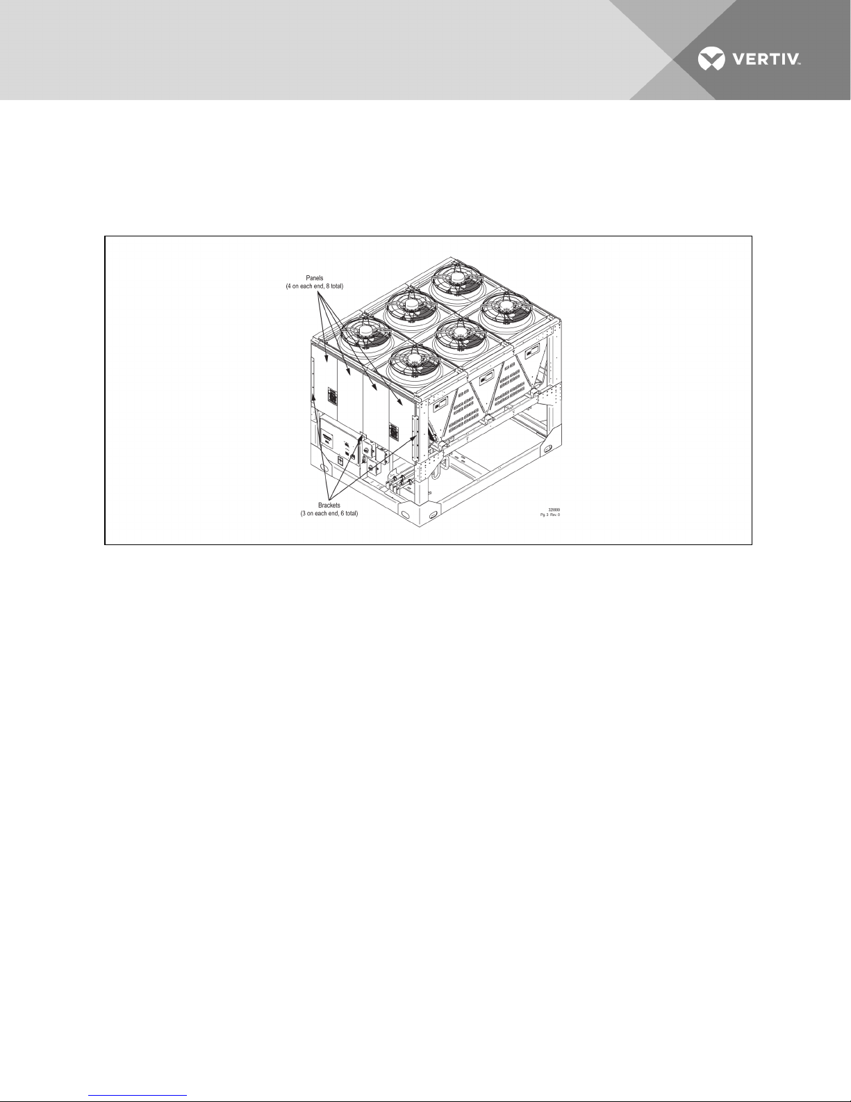
4.2 Remove Shipping Panels and Brackets
Shipping panels and securing brackets are located on each end of the unit. Before operating the unit,
remove the panels and brackets from both ends of the unit, Figure 4.1 below.
Figure 4.1 Shipping panels and securing brackets to remove
Vertiv | Liebert® MCV™ Installer/User Guide | 14
5 PIPING
All refrigeration connections to the unit are sweat copper. Factory-installed piping brackets must not be
removed. Field-installed piping must be installed in accordance with local codes and must be properly
assembled, supported, isolated and insulated.
Refer to specific text and detailed diagrams in this manual for other unit-specific piping requirements.
The following tables list the relevant documents by number and title.
Table 5.1 Piping General-arrangment Drawings
Document Number Titl e
DPN004476 PipingSchematic, Liebert MCV with Liebert DS E models DA125 to DA250
Table 5.2 Piping Connection Drawings
Document Number Titl e
DPN003877 Piping connection locations, MCV330
DPN004211 Piping connection locations, MCV440
5.1 Refrigerant Piping and Charging
WARNING! Risk of over-pressurization of the refrigeration system. Can cause explosive
discharge of high-pressure refrigerant, loss of refrigerant, environmental pollution, equipment
damage, injury, or death. This unit contains fluids and gases under high pressure. Use extreme
caution when charging the refrigerant system. Do not pressurize the system higher than the
design pressure marked on the unit's nameplate.
Consult local building and plumbing codes for installation requirements of additional pressure-relief
devices when isolation valves are field installed. Do not isolate any refrigerant circuits from overpressurization protection.
NOTICE
Risk of oil contamination with water. Can cause equipment damage.
LiebertMCV systems require the use of POE (polyolester) oil. POE oil absorbs water at a much
faster rate when exposed to air than previously used oils. Because water is the enemy of a
reliable refrigeration system, extreme care must be used when opening systems during
installation or service. If water is absorbed into the POE oil, it will not be easily removed and will
not be removed through the normal evacuation process. If the oil is too wet, it may require an oil
change. POE oils also have a property that makes them act as a solvent in a refrigeration
system. Maintaining system cleanliness is extremely important because the oil will tend to
bring any foreign matter back to the compressor.
Vertiv | Liebert® MCV™ Installer/User Guide | 15

5.1.1 Refrigerant Piping Guidelines forAir-cooledSystems
• Air-cooled units and condensers ship with an inert-gas holding charge. Do not vent the
evaporator until all refrigerant piping is in place, ready for connection to the unit and
condenser
• Use copper piping with a brazing alloy with a minimum temperature of 1350°F (732°C), such as
Sil-Fos. Avoid soft solders, such as 50/50 or 95/5.
• Use a flow of dry nitrogen through the piping during brazing to prevent formation of copper
oxide scale inside the piping. When copper is heated in the presence of air, copper oxide forms.
POE oils will dissolve these oxides from inside the copper pipes and deposit them throughout
the system, clogging filter driers and affecting other system components.
• A pure dry nitrogen flow of 1-3 ft3/min (0.5-1.5 l/s) inside the pipe during brazing is sufficient to
displace the air. Control the flow using a suitable measuring device.
• Ensure that the tubing surfaces to be brazed are clean and that all burrs have been removed
from the ends of the tubes.
• Ensure that all loose material has been cleaned from inside the tubing before brazing.
• Protect all refrigerant line components within 18in. (460mm) of the brazing site by wrapping
them with a wet cloth or with a suitable heat-sink compound.
• Isolate piping from building using vibration-isolating supports.
• Install traps on hot-gas (discharge) lines at the base of vertical risers over 5ft(1.5m) and every
20ft(6m) for vertical rises over 25 ft (7.6m), then install a trap in 20-ft (6-m) increments or
evenly-divided over the vertical rise.
• When connecting to a DA250 indoor unit: Install traps on hot-gas (discharge) lines at the base
of vertical risers over 5ft(1.5m) and every 20ft(6m) or evenly-divided over the vertical rise.
The DA250 has internally-installed traps on the hot-gas lines.
• Pitch horizontal hot-gas piping down at a minimum rate of 1/2in.per 10ft (42mm per 10m) so
that gravity will aid in moving oil in the direction of refrigerant/oil flow.
• When connecting to a DA165 indoor unit: Consult factory if piping run exceeds 300ft (91m)
actual length or 450ft(137.2m) equivalent length.
• Keep piping clean and dry, especially on units with R-410A refrigerant.
• Avoid piping runs through noise-sensitive areas.
• Do not run piping directly in front of discharge air stream.
• Refrigerant oil – do not mix oil types. Consult the indoor-unit installation/user guide for
refrigerant type and oil requirements.
Refer to ASHRAE Refrigeration Handbook for general, good-practice refrigeration piping. The indoor
cooling unit has a factory-installed high-pressure safety switch in the high side refrigerant circuit. A
fusible plug kit is installed in each Liebert MCV receiver.
NOTE: All indoor and outdoor field refrigerant piping must have 1/2 in. minimum of insulation. All
outdoor insulation must be UV and ozone resistant.
Vertiv | Liebert® MCV™ Installer/User Guide | 16

• Refer to the indoor unit's Installer/User Guide for recommended refrigerant piping sizes based
on equivalent pipe lengths.
• Refer to the indoor unit's Installer/User Guide for the refrigerant-charge requirements of the
system. Table 5.3 below, provides the approximate charge for an MCV condenser.
Table 5.3 Approximate R-410A refrigerant required per circuit for condenser with DSE large receiver
(dual circuit)
Condenser Model Charge per circuit, lb (kg)
MCV330 27.8 (12.6)
MCV440 34.6 (15.7)
5.1.2 Additional Oil Requirements
Refer to the indoor unit's Installer/User Guide to determine if additional oil is required for each circuit. The
need for additional oil is affected by compressor type, piping lengths, receiver, and total refrigerant
charge.
5.2 System Dehydration/Leak Test
Refer to the indoor unit's Installer/User Guide for the leak-check and evacuation procedures for the entire
thermal-management system. Refer to the section that refers to the winter control system used on the
condenser with Liebert DSE receivers.
5.3 Charging Condensers with DSE Receivers
Refer to the indoor unit's Installer/User Guide for the leak-check and evacuation procedures for the entire
thermal-management system. All Liebert DSE Thermal Management Systems require a DSEreceiver on
each condenser circuit whether or not the system includes a Liebert EconoPhase pump module.
Vertiv | Liebert® MCV™ Installer/User Guide | 17

This page intentionally left blank.
Vertiv | Liebert® MCV™ Installer/User Guide | 18
6 ELECTRICAL CONNECTIONS
Line-voltage electrical service is required for all models. Electrical service must conform to national and
local electrical codes. Refer to equipment nameplate regarding wire size and circuit protection
requirements. Refer to electrical schematic when making connections. Refer the appropriate submittal
drawing, listed in Table 6.1 on the next page, for electrical service entrances into unit.
A manual electrical disconnect switch should be installed in accordance with local codes and distribution
system. Consult local codes for external disconnect requirements.
All internal wiring is completed at the factory.
WARNING! Arc flash and electric shock hazard. Open all local and remote electric power-supply
disconnect switches, verify with a voltmeter that power is Off and wear appropriate,
OSHA-approved personal protective equipment (PPE) per NFPA 70E before working within the
electric control enclosure. Failure to comply can cause serious injury or death. Customer must
provide earth ground to unit, per NEC, CEC and local codes, as applicable. Before proceeding
with installation, read all instructions, verify that all the parts are included and check the
nameplate to be sure the voltage matches available utility power. The Liebert controller does
not isolate power from the unit, even in the “Unit Off” mode. Some internal components require
and receive power even during the “Unit Off” mode of the controller. The only way to ensure
that there is NO voltage inside the unit is to install and open a remote disconnect switch. Refer
to unit electrical schematic. Follow all local codes.
WARNING! Risk of improper wiring, piping, moving, lifting and handling. Can cause equipment
damage, serious injury or death. Installation and service of this equipment should be done only
by qualified personnel, wearing appropriate, OSHA-approved PPE, who have been speciallytrained in the installation of air-conditioning equipment.
WARNING! Risk of contact with high-speed rotating fan blades. Can cause serious injury or
death. If control voltage is applied, the fan motor can restart without warning after a power
failure. Open all local and remote electric power-supply disconnect switches, verify with a
voltmeter that power is off, and verify that all fan blades have stopped rotating before working
on the fan assembly. After working on the fan assembly, remove any used tools or other
objects from the unit cabinet before restoring electric power.
NOTE: Use copper wiring only. Make sure that all connections are tightened to the proper torque
mentioned on the component.
The electrical connections are described in the submittal documents included in the Submittal Drawings
on page57.
Vertiv | Liebert® MCV™ Installer/User Guide | 19

The following tables list the relevant documents by number and title.
Table 6.1 Electrical Field-connection Drawings
Document Number Titl e
DPN003879 Electrical FieldConnections, MCV330
DPN004212 E lectrical Field Connections, MCV440
DPN003886 CANbus and Interlock Connections between Unitand Condenser
6.1 Line Voltage Wiring
WARNING! Risk of electrical fire and short circuit. Can cause property damage, injury or death.
Select and install the line side electrical supply wire and overcurrent protection device(s)
according to the specifications on the unit nameplate(s), per the instructions in this manual
and according to the applicable national, state and local code requirements. Use copper
conductors only. Verify that all electrical connections are tight. Unit-specific wiring diagrams
are provided on each unit.
NOTE: The electrically commutated (EC) motors included in the Liebert MCV Condenser are suitable
for connection to power supplies with a solidly-grounded neutral or high-resistance to ground or
corner ground.
Condenser-rated voltage should be verified with available power supply before installation. Refer to the
unit’s electrical schematic and serial tag for specific electrical requirements.
Liebert MCV condenser power connections are provided for three-phase wires and 1 earth ground wire.
Line voltage electrical service is required for all condensers at the location of the condenser. The voltage
supply to the condenser may not be the same voltage supply as required by the indoor unit. Consider
using a UPS on both data center cooling units and MCV condensers to maintain uninterrupted cooling
capability. Refer to the unit’s serial tag for specific condenser electrical requirements. A unit disconnect is
standard. However, a site disconnect may be required by local code to isolate the unit for maintenance.
Route the supply power to the site disconnect switch and then to the unit. Route the conduit to the
knockout provided in the bottom right end of the electrical control enclosure. Connect the earth ground
wire lead to the marked earth ground connection terminal provided near the factory-installed disconnect
switch the appropriate drawing in the Submittal Drawings on page57..
Table 6.2 Electrical data, three-phase, 60Hz condenser, premium models
Model Suppl y Power: 460- 3-60 380-3-60 415-3-50
FLA 16.8 21.0 21
MCV330
MCV440
WSA 17.5 21.9 21.9
OPD 20 25 25
FLA 22.4 28.0 28
WSA 23.1 28.9 28.9
OPD 25 35 35
NOTE: A separate neutral wire does not need to be run to the MCV.
Vertiv | Liebert® MCV™ Installer/User Guide | 20

6.1.1 Acceptable Power Supplies—380V to 460V Nominal Units
• 380V Wye with solidly grounded neutral and 220V line-to-ground
• 480V Wye with solidly grounded neutral and 277V line-to-ground
• Wye with high-resistance (or impedance) ground
• Delta with corner ground
6.1.2 Unacceptable Power Supplies
• Delta without ground or with floating ground
• Delta with grounded center tap
Vertiv | Liebert® MCV™ Installer/User Guide | 21

This page intentionally left blank.
Vertiv | Liebert® MCV™ Installer/User Guide | 22
 Loading...