


Liebert® MBX Busway System
Optional Busway System Monitoring
Installer/User Guide

The information contained in this document is subject to change
without notice and may not be suitable for all applications. While
every precaution has been taken to ensure the accuracy and
completeness of this document, Vertiv™ assumes no responsibility
and disclaims all liability for damages resulting from use of this
information or for any errors or omissions. Refer to other local
practices or building codes as applicable for the correct methods,
tools, and materials to be used in performing procedures not
specifically described in this document.
The products covered by this instruction manual are manufactured
and/or sold by Vertiv. This document is the property of Vertiv and
contains confidential and proprietary information owned by Vertiv.
Any copying, use or disclosure of it without the written permission
of Vertiv is strictly prohibited.
Names of companies and products are trademarks or registered
trademarks of the respective companies. Any questions regarding
usage of trademark names should be directed to the original
manufacturer.
Technical Support Site
If you encounter any installation or operational issues with your product, check the pertinent
section of this manual to see if the issue can be resolved by following outlined procedures.
Visit https://www.Vertiv.com/en-us/support/ for additional assistance.
Vertiv™ | Liebert® MBX MonitoringInstaller/UserGuide

TABLE OF CONTENTS
1 Installation 1
1.1 End Feed Box Monitoring Setup 1
1.2 End Feed Box Ethernet Configuration 1
1.3 End Feed Box USB Configuration 2
2 Tap-Off Box Monitoring 5
3 Web Portal Configuration 7
4 Firmware Update 9
i

This page intentionally left blank
ii
Vertiv™ | Liebert® MBX MonitoringInstaller/User Guide

1 INSTALLATION
Vertiv™ offers optional monitoring packages for the Liebert® MBX Busway System End Feed Box and TapOff Box using Socomec DIRIS Digiware.
• End Feed Box Only Package: Includes DIRIS Digiware G-30, I-45 and U-30
• End Feed Box and Tap-Off Box Package: Includes DIRIS Digiware G-30, I-45, U-30, I-30 and C-31
interface module.
1.1 End Feed Box Monitoring Setup
NOTE: Before beginning to test or program any Digiware components in the Tap-Off Box, ensure that
your G-30 and U-30 Modules are configured.
For the G-30 Module ensure:
• All settings are set to default unless otherwise required by the client.
• Set the address to 1.
For the U-30 Module ensure:
• All settings are set to default unless otherwise required by the client.
• Set the address to 2.
NOTE: The addresses for the G-30 Module and the U-30 Module must not conflict.
NOTE: The G-30 must be programmed first, followed by the U-30, then any I-modules. The U-30
Module governs all I-modules’ baud rate and parity. Always check when testing I-modules that the
baud rate programmed into the U-30 carried over to the I-module.
1.2 End Feed Box Ethernet Configuration
1. Power ON the
2. Connect the
3. Browse to
4. Click the
5. Log in to the
6. Click
7. Enter a Name for the End Feed Box.
8. Select
9. Enter the IP address. The default address is
10. Click
11. Click
12. Check the following settings:
Add
DIRIS G-30/G-40/G-50/G60
Save
Connect To Device
a. Verify that the latest firmware is installed on the device. You can check the latest firmware
version on the "Socomec" website. If firmware needs updated, see Firmware Update on page 9 for
instructions.
b. Set the IP address and set the address (Slave ID) to 1.
End Feed Box
G-30 Module
www.Socomec.us,
.
to your laptop using a standard straight through CAT5 ethernet cable.
download and install the latest Easy Config software.
Change Profile Button
Super User
a Device.
.
profile using password "sOcOmec".
.
in the upper right corner of Easy Config.
from the Type drop down menu.
192.168.0.2.
1 Installation
1

c. Set the Baud rate, Stop bits and Parity. The default settings are 38400/1/N. On the U-30
Modules, click the
Network Tab
. Confirm the power system settings are correct for the customer
site:
• Network Type
• Nominal Voltage
• Frequency
• Phase Rotation
NOTE: Record the serial number of each G-30 Module for future reference.
13. G-30 Only: Click the
14. G-30 Only: Click the
Device Detection Tab
New Discovery Button
.
and wait till discovery is complete, approximately 3
minutes.
15. After checking all the settings, click
16. Select the
17. Click
G-30orU-30 Module
Select All
, then click
OK.
Final Action
, then click
Send to Device
being programmed, then click
.
Connect to Device
.
18. Wait for the configuration to be sent to the device. When the successful operation message pops up,
clickOK.
19. Return to the home screen in Easy Config. Click
20. Select the
U-30 Module
and Repeat Step 11 through Step 17, changing the address (Slave ID) to 2
Get From Device
.
for the U-30 Device.
1.3 End Feed Box USB Configuration
NOTE: Micro-USB cable must be a data and power cable. Power-only cables will not function.
To configure the End Feed Box monitoring device:
1. Power On the End Feed Box and ensure that the G-30 and U-30 Modules are On.
2. Connect the G-30 Module to your laptop using USB – micro USB lead.
3. Browse to
www.Socomec.us,
download and install the latest Easy Config software.
4. Click the
Change Profile
Button in the upper right corner of Easy Config.
5. Log in to the Super User profile using password "sOcOmec".
6. Open the
7. Click the device to configure, then click
Easy Config
software and select
Get Configuration from Device.
Connect to Device
. If no device is visible, verify that the G-30
Module is powered On and that the USB – Micro USB lead is connected correctly.
8. Check these settings:
a. Verify that the latest firmware is installed on the device. You can check the latest firmware
version on the "Socomec" website. If firmware needs updated, see Firmware Update on page 9 for
instructions.
b. Set the IP address and set the address (Slave ID) to 1.
c. Set the baud rate, stop bits and parity. The default settings are 38400/1/N. On U-30 Modules,
click the
Network Tab
. Confirm the power system settings are correct for the customer
site:
2
Vertiv™ | Liebert® MBX MonitoringInstaller/User Guide

• Network Type
• Nominal Voltage
• Frequency
• Phase Rotation
NOTE: Record the serial number of each G30 Module for future reference.
9. G-30 Only: Click the
10. G-30 Only: Click the
Device Detection Tab
New Discovery Button
.
and wait till the discovery is complete, approximately 3
minutes.
11. After checking all settings, click
12. Select the G-30 or U-30 Module being programmed, then click
13. Click
Select All
, then clickOK.
Final Action
, then click
Send to Device
Connect to Devic
.
e.
14. Wait for the configuration to be sent to the device. When the successful operation message pops up,
clickOK.
15. Remove the micro USB from the G-30 Module and insert it into the U-30 Module to configure the U30 Module.
16. Repeat Step 6 through Step 14, changing the address (Slave ID) to 2 for the U-30 Device.
NOTE: Record the serial number of each U-30 Module for future reference. The C-31 interface module
provides RS-485 Modbus and Digiware Bus communication support to an external network.
Figure 3.1 Optional Ethernet Connection
1 Installation
3

This page intentionally left blank
4
Vertiv™ | Liebert® MBX MonitoringInstaller/User Guide

2 TAP-OFF BOX MONITORING
If your Tap-Off Box is equipped with a monitoring option, there will be two RJ-45 jacks on the side of the
enclosure. The Tap-Off Box RJ-45 connections must be daisy-chained from Tap-Off Box to Tap-Off Box
with the final connection made at the End Feed Box that houses the gateway device. The last Tap-Off Box
in the daisy-chain must have a "Socomec" termination plug installed in the final RJ-45 jack.
NOTE: You can daisy-chain a maximum of 26 Tap-Off Boxes to the network gateway device, located in
the End Feed Box. If you need to daisy chain more than 26, a repeater Tap-Off Box is required. Consult
your sales representative for information on repeater Tap-Off Boxes.
NOTE: Before beginning to test or program any Digiware components in the Tap-Off Boxes, ensure
that your G-30 Module and U-30 Module are configured. The U-30 Module governs the baud rate and
parity for all I-modules. Alwayas check when testing I-modules that the baud rate programmed into the
U-30 carried over to the I-module.
To configure Tap-Off Boxes:
1. Power On the I-30 or I-60 using a Socomec RJ-45 cable, which is looped out from the U-30 Module. A
green light appears on the I-30 or I-60 Module to indicate it is powered On.
2. Connect the I-module to your laptop via USB – micro USB lead.
3. Click the
4. Log in to the Super User profile using password "sOcOmec".
5. Click
change profile button
Get from Device.
in the upper right corner of Easy Config.
6. Click the
7. Select the
• Identification – I-30 OR I-60 Serial Number
• Type – Device Connected
• Firmware Version – Latest firmware installed. You can check the latest firmware version on the
• The ‘Communication Configuration’ shown is :
8. Select
• Load Enabled – If CTs are connected, option to change settings.
• Load Type – Select number of phases and amount of CTs.
• Nominal Current – circuit rating associated with each CT.
Device
"Socomec" website. If firmware needs updated, see Firmware Update on page 9 for instructions.
• Type – RS485.
• Address – Set a unique Modbus address. The G-30 is 1, U-30 is 2, I-45 (if present) is 5.
Continue numbering I-modules starting at 10.
• Baud Rate – Confirm match to U-30 settings.
• Stop Bits – Confirm match to U-30 settings.
• Parity – Confirm match to U-30 settings.
Load
to configure, then click
Product
and confirm the following information:
Tab and verify the following information:
Connect to Device
.
• CT Direction – If the CTs are reading an incoming or outgoing supply.
9. After the settings are updated, click
2 Tap-Off Box Monitoring
Final Action,
then click
Send to Device
.
5

10. Select the
I-module
being programmed, then click
Connect to Device
.
11. Click Select All, then clickOK.
12. Wait for the configuration to be sent to the device. When the successful operation message pops up,
clickOK.
NOTE: After completing all the I-module configurations or after adding new Tap-Off Box Modules to a
busway run, you must log into the G-30 module and re-perform device discovery.
1. Connect to the G-30 via Ethernet or USB.
2. Click
Device Detection
Tab.
3. Click
4. Click
5. Click
6. Select the G-30 Module and click
New Discovery
Final Action
.
Send to Device
. All newly configured I-modules should appear.
.
Connect To Device
7. Click Select All then ClickOk.
8. Wait for the configuration to be sent. ClickOk.
.
6
Vertiv™ | Liebert® MBX MonitoringInstaller/User Guide

3 WEB PORTAL CONFIGURATION
After completing all the I-module configurations or after adding a new Tap-Off Box Module to a busway
run, you must log in into the Socomec web portal and update the configuration.
1. Click the
2. Select
3. Click the
4. Click
5. Click
6. Confirm all modules appear.
7. Click
Change Profile
Admin
and enter password
Settings Gear
Devices.
Read Configuration.
Save Configuration
Button in the upper right corner.
Icon on the top left.
.
Admin
.
3 Web Portal Configuration
7

This page intentionally left blank
8
Vertiv™ | Liebert® MBX MonitoringInstaller/User Guide
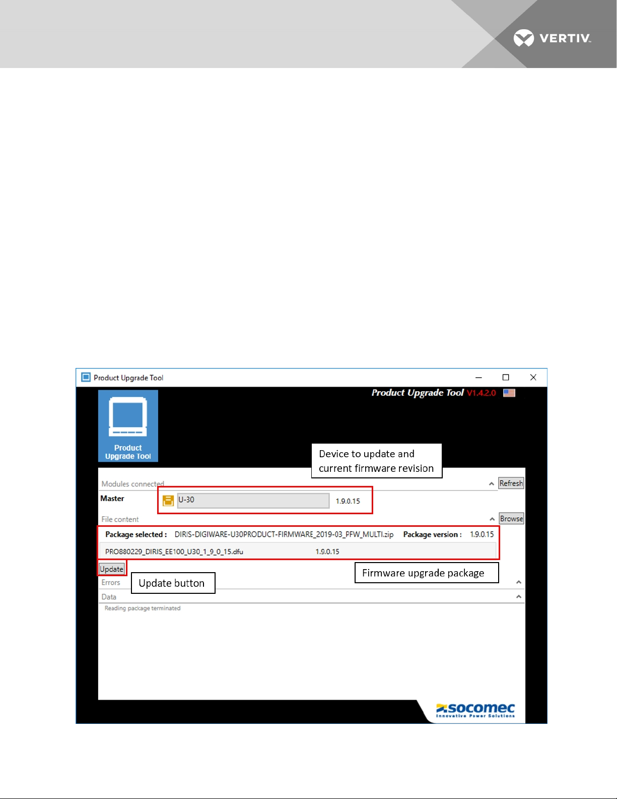
4 FIRMWARE UPDATE
If the firmware for each device is not the latest available on the Socomec website, download the firmware
ZIP file for the module(s) to be updated. Firmware versions may be checked on the Socomec website:
https://www.socomec.com/product-upgrade-tool-software_en.html
To update a Socomec Digiware module firmware, perform the following steps:
1. Download the latest version of Socomec’s Product Upgrade Tool and firmware version from the page
above.
2. Install the Product Upgrade Tool on your laptop.
3. Connect the module to your laptop via USB – micro USB lead.
4. Open the Product Upgrade Tool program.
5. Verify the module to be upgraded is displayed in the Master field.
6. Click the
Browse
button and select the firmware ZIP file for the module.
.
7. Click
8. Configure the module per the instructions in section 1 or 2.
Figure 6.1 Product Upgrade Tool
Update
and wait for the firmware upgrade to complete.
4 Firmware Update
9

This page intentionally left blank
10
Vertiv™ | Liebert® MBX MonitoringInstaller/User Guide

Vertiv™ | Liebert® MBX MonitoringInstaller/User Guide

Vertiv.com | Vertiv Headquarters, 1050 Dearborn Drive, Columbus, OH, 43085, USA
© 2020 VertivGroup Corp. Allrights reserved. Vertiv™ and the Vertiv logo are trademarks or registered trademarks of Vertiv Group Corp. All other names
and logos referred to are trade names, trademarks or registered trademarks of their respective owners. While every precaution has been taken to ensure
accuracy and completeness herein, Vertiv Group Corp. assumes no responsibility, and disclaims all liability, for damages resulting from use of this information
or for anyerrors or omissions. Specifications are subject to change without notice..
SL-70526_REV02_05-20
 Loading...