

Page 1

Liebert® ITA2™ MBC™, 8-10kVA, 208/220V,
Three-Phase Maintenance Bypass Cabinet
User Manual
Page 2

Contacting Vertiv™ for Support
To contact Vertiv Services for information or repair service in the United States, call 800-543-2378. Vertiv
Services offers a complete range of startup services, repair services, preventive maintenance plans and service
contracts.
For repair or maintenance service outside the 48 contiguous United States, contact Vertiv Services, if available in
your area.
For Vertiv Services to assist you promptly, have the following information available:
Part Numbers:
Serial Numbers:
Rating:
Date Purchased:
Date Installed:
Location:
Battery Voltage:
Battery Reserve Time:
Page 3

TABLE OF CONTENTS
IMPORTANT SAFETY INSTRUCTIONS . . . . . . . . . . . . . . . . . . . . . . . . . . . . . . . . . . . . . . . . . . . . . . . .1
SAVE THESE INSTRUCTIONS . . . . . . . . . . . . . . . . . . . . . . . . . . . . . . . . . . . . . . . . . . . . . . . . . . . . . . . . 1
1.0 INTRODUCTION. . . . . . . . . . . . . . . . . . . . . . . . . . . . . . . . . . . . . . . . . . . . . . . . . . . . . . . . . . . . . . 4
1.1 Components . . . . . . . . . . . . . . . . . . . . . . . . . . . . . . . . . . . . . . . . . . . . . . . . . . . . . . . . . . . . . . . . . . . . . . . . . . . . . . . . . . . . . 4
1.2 Operation Modes . . . . . . . . . . . . . . . . . . . . . . . . . . . . . . . . . . . . . . . . . . . . . . . . . . . . . . . . . . . . . . . . . . . . . . . . . . . . . . . . 6
1.3 UPS Mode . . . . . . . . . . . . . . . . . . . . . . . . . . . . . . . . . . . . . . . . . . . . . . . . . . . . . . . . . . . . . . . . . . . . . . . . . . . . . . . . . . . . . . . 6
1.4 Maintenance Bypass Mode. . . . . . . . . . . . . . . . . . . . . . . . . . . . . . . . . . . . . . . . . . . . . . . . . . . . . . . . . . . . . . . . . . . . . . . .7
2.0 INSTALLATION AND OPERATION . . . . . . . . . . . . . . . . . . . . . . . . . . . . . . . . . . . . . . . . . . . . . 8
2.1 Mechanical Installation . . . . . . . . . . . . . . . . . . . . . . . . . . . . . . . . . . . . . . . . . . . . . . . . . . . . . . . . . . . . . . . . . . . . . . . . . . . .8
2.1.1 Tower Installation. . . . . . . . . . . . . . . . . . . . . . . . . . . . . . . . . . . . . . . . . . . . . . . . . . . . . . . . . . . . . . . . . . . . . . . . . . . . . . . . . 8
2.1.2 Rack Installation . . . . . . . . . . . . . . . . . . . . . . . . . . . . . . . . . . . . . . . . . . . . . . . . . . . . . . . . . . . . . . . . . . . . . . . . . . . . . . . . . . 9
2.2 Connecting Liebert ITA2 MBC Cables. . . . . . . . . . . . . . . . . . . . . . . . . . . . . . . . . . . . . . . . . . . . . . . . . . . . . . . . . . . . .12
2.2.1 Selecting Cables . . . . . . . . . . . . . . . . . . . . . . . . . . . . . . . . . . . . . . . . . . . . . . . . . . . . . . . . . . . . . . . . . . . . . . . . . . . . . . . . . .12
2.2.2 Connecting Power Cables . . . . . . . . . . . . . . . . . . . . . . . . . . . . . . . . . . . . . . . . . . . . . . . . . . . . . . . . . . . . . . . . . . . . . . . . . 12
2.3 Single-Input Configuration—Factory Default . . . . . . . . . . . . . . . . . . . . . . . . . . . . . . . . . . . . . . . . . . . . . . . . . . . . . .12
2.3.1 Connecting the Main Input Cables-Single Input . . . . . . . . . . . . . . . . . . . . . . . . . . . . . . . . . . . . . . . . . . . . . . . . . . . .13
2.3.2 Connecting the Main Output Cables-Single Input . . . . . . . . . . . . . . . . . . . . . . . . . . . . . . . . . . . . . . . . . . . . . . . . . .13
2.3.3 Cable Connections from the Liebert ITA2 MBC to the UPS—Single-Input . . . . . . . . . . . . . . . . . . . . . . . . . . .13
2.4 Dual-Input Configuration . . . . . . . . . . . . . . . . . . . . . . . . . . . . . . . . . . . . . . . . . . . . . . . . . . . . . . . . . . . . . . . . . . . . . . . . .14
2.4.1 Dual-Input Configuration—Main Input . . . . . . . . . . . . . . . . . . . . . . . . . . . . . . . . . . . . . . . . . . . . . . . . . . . . . . . . . . . . 14
2.4.2 Dual-Input Configuration—Rectifier Input. . . . . . . . . . . . . . . . . . . . . . . . . . . . . . . . . . . . . . . . . . . . . . . . . . . . . . . . . 14
2.4.3 Dual-Input Configuration—Bypass Input . . . . . . . . . . . . . . . . . . . . . . . . . . . . . . . . . . . . . . . . . . . . . . . . . . . . . . . . . . 14
2.4.4 Dual-Input Configuration—Main Output . . . . . . . . . . . . . . . . . . . . . . . . . . . . . . . . . . . . . . . . . . . . . . . . . . . . . . . . . . .15
2.4.5 Cable Connections from the Liebert ITA2 MBC to the UPS—Dual-Input . . . . . . . . . . . . . . . . . . . . . . . . . . . . .15
2.5 Connect the Communication Cables . . . . . . . . . . . . . . . . . . . . . . . . . . . . . . . . . . . . . . . . . . . . . . . . . . . . . . . . . . . . . . 17
3.0 POD ASSEMBLY . . . . . . . . . . . . . . . . . . . . . . . . . . . . . . . . . . . . . . . . . . . . . . . . . . . . . . . . . . . . . .18
3.1 Installing the POD. . . . . . . . . . . . . . . . . . . . . . . . . . . . . . . . . . . . . . . . . . . . . . . . . . . . . . . . . . . . . . . . . . . . . . . . . . . . . . . .18
4.0 OPERATING THE LIEBERT ITA2 MBC . . . . . . . . . . . . . . . . . . . . . . . . . . . . . . . . . . . . . . . . . 20
4.1 Startup . . . . . . . . . . . . . . . . . . . . . . . . . . . . . . . . . . . . . . . . . . . . . . . . . . . . . . . . . . . . . . . . . . . . . . . . . . . . . . . . . . . . . . . . . 20
4.2 Shutdown . . . . . . . . . . . . . . . . . . . . . . . . . . . . . . . . . . . . . . . . . . . . . . . . . . . . . . . . . . . . . . . . . . . . . . . . . . . . . . . . . . . . . . 20
4.3 Transfer UPS from Normal Mode to Maintenance Bypass Mode. . . . . . . . . . . . . . . . . . . . . . . . . . . . . . . . . . . . 21
4.4 Transfer UPS from Maintenance Bypass Mode to Normal Mode . . . . . . . . . . . . . . . . . . . . . . . . . . . . . . . . . . . . 21
5.0 SPECIFICATIONS . . . . . . . . . . . . . . . . . . . . . . . . . . . . . . . . . . . . . . . . . . . . . . . . . . . . . . . . . . . . 22
Vertiv |Liebert® ITA2™, 8-10kVA, 208/220V Three-Phase MBC User Manual | Rev. 0 | 02/18 | 1
Page 4

FIGURES
Figure 1 Appearance of Liebert ITA2 MBC . . . . . . . . . . . . . . . . . . . . . . . . . . . . . . . . . . . . . . . . . . . . . . . . . . . . . . . . . . . . . 4
Figure 2 Front panel of Liebert ITA2 MBC . . . . . . . . . . . . . . . . . . . . . . . . . . . . . . . . . . . . . . . . . . . . . . . . . . . . . . . . . . . . . . 4
Figure 3 Rear panel of the single POD . . . . . . . . . . . . . . . . . . . . . . . . . . . . . . . . . . . . . . . . . . . . . . . . . . . . . . . . . . . . . . . . . .5
Figure 4 Power distribution area of Liebert ITA2 MBC . . . . . . . . . . . . . . . . . . . . . . . . . . . . . . . . . . . . . . . . . . . . . . . . . . .5
Figure 5 Operating principle of Liebert ITA2 MBC . . . . . . . . . . . . . . . . . . . . . . . . . . . . . . . . . . . . . . . . . . . . . . . . . . . . . . 6
Figure 6 UPS mode . . . . . . . . . . . . . . . . . . . . . . . . . . . . . . . . . . . . . . . . . . . . . . . . . . . . . . . . . . . . . . . . . . . . . . . . . . . . . . . . . . . 6
Figure 7 Maintenance bypass mode . . . . . . . . . . . . . . . . . . . . . . . . . . . . . . . . . . . . . . . . . . . . . . . . . . . . . . . . . . . . . . . . . . . .7
Figure 8 Connecting the support base with support base extension . . . . . . . . . . . . . . . . . . . . . . . . . . . . . . . . . . . . .8
Figure 9 Liebert ITA2 MBC, UPS and battery module Installation complete . . . . . . . . . . . . . . . . . . . . . . . . . . . . . . 9
Figure 10 Installing brackets . . . . . . . . . . . . . . . . . . . . . . . . . . . . . . . . . . . . . . . . . . . . . . . . . . . . . . . . . . . . . . . . . . . . . . . . . . . 9
Figure 11 Guide rail orientation for installation . . . . . . . . . . . . . . . . . . . . . . . . . . . . . . . . . . . . . . . . . . . . . . . . . . . . . . . . . .10
Figure 12 Installing the left guide rail . . . . . . . . . . . . . . . . . . . . . . . . . . . . . . . . . . . . . . . . . . . . . . . . . . . . . . . . . . . . . . . . . . .10
Figure 13 Guide rail installation complete . . . . . . . . . . . . . . . . . . . . . . . . . . . . . . . . . . . . . . . . . . . . . . . . . . . . . . . . . . . . . . . 11
Figure 14 Installing the Liebert ITA2 MBC. . . . . . . . . . . . . . . . . . . . . . . . . . . . . . . . . . . . . . . . . . . . . . . . . . . . . . . . . . . . . . . 11
Figure 15 System installation layout—rack . . . . . . . . . . . . . . . . . . . . . . . . . . . . . . . . . . . . . . . . . . . . . . . . . . . . . . . . . . . . . . 11
Figure 16 Liebert ITA2 MBC cable connections. . . . . . . . . . . . . . . . . . . . . . . . . . . . . . . . . . . . . . . . . . . . . . . . . . . . . . . . . .14
Figure 17 Liebert ITA2 UPS cable connections . . . . . . . . . . . . . . . . . . . . . . . . . . . . . . . . . . . . . . . . . . . . . . . . . . . . . . . . . .16
Figure 18 Dry contact ports on Liebert ITA2 MBC and UPS . . . . . . . . . . . . . . . . . . . . . . . . . . . . . . . . . . . . . . . . . . . . . . 17
Figure 19 Removing POD cover panel. . . . . . . . . . . . . . . . . . . . . . . . . . . . . . . . . . . . . . . . . . . . . . . . . . . . . . . . . . . . . . . . . . .18
Figure 20 Connecting PP75 terminals . . . . . . . . . . . . . . . . . . . . . . . . . . . . . . . . . . . . . . . . . . . . . . . . . . . . . . . . . . . . . . . . . . .19
Figure 21 Angle the POD for installation . . . . . . . . . . . . . . . . . . . . . . . . . . . . . . . . . . . . . . . . . . . . . . . . . . . . . . . . . . . . . . . .19
Figure 22 Front panel of Liebert ITA2 MBC . . . . . . . . . . . . . . . . . . . . . . . . . . . . . . . . . . . . . . . . . . . . . . . . . . . . . . . . . . . . . 20
TABLES
Table 1 GLOSSARY OF SYMBOLS . . . . . . . . . . . . . . . . . . . . . . . . . . . . . . . . . . . . . . . . . . . . . . . . . . . . . . . . . . . . . . . . . . . . .3
Table 2 Liebert ITA2 MBC currents and cables—User and UPS rectifier input . . . . . . . . . . . . . . . . . . . . . . . . . .12
Table 3 Liebert ITA2 MBC currents and cables—User and UPS bypass input and output. . . . . . . . . . . . . . . . 12
Table 4 Recommended lug sizes. . . . . . . . . . . . . . . . . . . . . . . . . . . . . . . . . . . . . . . . . . . . . . . . . . . . . . . . . . . . . . . . . . . . . .12
Table 5 POD specifications . . . . . . . . . . . . . . . . . . . . . . . . . . . . . . . . . . . . . . . . . . . . . . . . . . . . . . . . . . . . . . . . . . . . . . . . . . .18
Table 6 Liebert ITA2 MBC specifications . . . . . . . . . . . . . . . . . . . . . . . . . . . . . . . . . . . . . . . . . . . . . . . . . . . . . . . . . . . . . 22
Table 7 Hazardous substances in Liebert ITA2 8kVA 208V and 10kVA 208V Liebert ITA2 MBC . . . . . . . . 22
Vertiv |Liebert® ITA2™, 8-10kVA, 208/220V Three-Phase MBC User Manual | Rev. 0 | 02/18 | 2
Page 5

IMPORTANT SAFETY INSTRUCTIONS
SAVE THESE INSTRUCTIONS
This manual contains important safety instructions about installing and operating the Liebert ITA2 MBC
(maintenance bypass cabinet). Read all safety, installation and operating instructions before beginning to install
or operate the Liebert ITA2 or the Liebert ITA2 MBC. Adhere to all warnings on the unit and in this manual. Follow
all operating and user instructions. Users must fully understand this equipment to install and operate it.
The Liebert ITA2 MBC is designed for commercial/industrial use only. It is not intended for use with life support
or other designated critical devices. Maximum load must not exceed that shown on the unit’s rating label. Install
and operate the Liebert ITA2 MBC only in a clean indoor environment, free of conductive contaminants,
moisture, flammable liquids, gases and corrosive substances. The Liebert ITA2 MBC contains no
user-serviceable parts. Refer all faults to your local dealer, local Vertiv representative or Vertiv Services.
The Liebert ITA2 UPS system with Liebert ITA2 MBC is designed for use on a properly earthed (grounded),
208/220V AC supply. The system must be installed only by properly trained and qualified personnel. A qualified
electrician must review and approve customer-supplied wiring, circuit breakers and intended loads and verify
correct input, output and earth connections to ensure compliance with the technical standards and local
electrical codes.
WARNING
Risk of electrical shock and high short circuit current. Can cause injury or death.
The following precautions must be observed before replacing the battery pack:
• Wear rubber gloves and boots
• Remove rings, watches and other metal objects.
• Use tools with insulated handles.
• Do not lay tools or other metal objects on the batteries.
• If the battery kit is damaged in any way or shows signs of leakage, contact your local Vertiv
representative immediately.
• Do not dispose of batteries in a fire. The batteries may explode.
• Handle, transport and recycle batteries in accordance with local regulations.
WARNING
Risk of electrical shock, fire and high short circuit current. Can cause injury or death.
The Liebert ITA2 MBC has been designed and manufactured to ensure personal safety, but improper use
can result in electrical shock or fire. To ensure safety, observe the following precautions:
• Turn Off and unplug the Liebert ITA2 MBC before cleaning it.
• Clean the unit with a dry cloth. Do not use liquid or aerosol cleaners.
• Never block or insert any objects into the ventilation holes or other openings of the Liebert ITA2 MBC.
• Do not place the Liebert ITA2 MBC power cord where it might be damaged.
WARNING
Risk of exposure to hazardous chemical.
This product contains a chemical known to the State of California to cause cancer and birth defects or
other reproductive harm.
Vertiv | Liebert® ITA2™, 8-10kVA, 208/220V Three-Phase MBC User Manual | Rev. 0 | 02/18 | 1
Page 6

ELECTROMAGNETIC COMPATIBILITY—The Liebert ITA2 MBC complies with the limits of Category C2,
pursuant to IEC/EN/AS 62040-2 and for a Class A digital device, pursuant to Part 15 Subpart B of FCC rules.
Operation is subject to the following conditions:
• The output cables must be no longer than 32ft (10m).
• This device must not cause harmful electromagnetic interference.
• This device must accept any interference received, including interference that may cause undesired operation. Operating
this device in a residential area is likely to cause harmful interference that users must correct at their own expense.
The Liebert ITA2 MBC complies with the requirements of EMC Directive 2004/108/EC and the published
technical standards. Continued compliance requires installation in accordance with these instructions and use of
accessories approved by Vertiv.
NOTICE
This is a Category C2 UPS product. In a residential environment, this product may cause radio interference, in which case
the user may be required to take additional measures.
Operate the unit in an indoor environment only in an ambient temperature range of 32-104°F (0-40°C). Install it in a clean
environment, free from moisture, flammable liquids, gases and corrosive substances.
This Liebert ITA2 MBC contains no user-serviceable parts except the internal battery pack. The unit’s On/Off push
buttons do not electrically isolate internal parts. Under no circumstances attempt to gain access internally, due to the risk
of electric shock or burn.
Do not continue to use the Liebert ITA2 MBC if the front panel indications are not in accordance with these operating
instructions or the performance alters in use. Refer all faults to your Vertiv representative or Vertiv Services.
Servicing of batteries must be performed or supervised by properly trained and qualified personnel knowledgeable of
batteries and the required precautions. Keep unauthorized personnel away from the batteries. Proper disposal of batteries
is required. Refer to your local laws and regulations for disposal requirements.
Never block or insert any object into the ventilation holes or other openings.
NOTICE
This product uses components that are dangerous for the environment, such as electronic
cards and other electronic components. Any component that is removed must be taken to
specialized collection and disposal centers. If this unit must be dismantled, this must be
done by a specialized center for collection and disposal of electric and electrical appliances
or other dangerous substances.
This product has been supplied from an environmentally aware manufacturer that complies
with the Waste Electrical and Electronic Equipment (WEEE) Directive 2012/19/EU.
Please be environmentally responsible and recycle this product through your recycling
facility at its end of life. Do not dispose of this product as unsorted municipal waste. Follow
local municipal waste ordinances for proper disposal provisions to reduce the
environmental impact of WEEE.
The “crossed-out wheelie bin symbol” is placed on this product to encourage you to recycle
whenever possible.
DO NOT CONNECT equipment that could overload the UPS or demand DC current from the Liebert ITA2 MBC,
for example: electric drills, vacuum cleaners, laser printers, hair dryers or any appliance using half-wave
rectification.
Storing magnetic media on top of the Liebert ITA2 MBC may result in data loss or corruption.
Information for the Protection of the Environment
UPS Servicing—This unit makes use of components dangerous for the environment (electronic cards,
electronic components). The components removed must be taken to specialized collection and disposal centers.
Notice to European Union Customers: Disposal of Old Appliances—This product has been supplied from an
environmentally aware manufacturer that complies with the Waste Electrical and Electronic Equipment (WEEE)
Directive 2002/96/CE.
Vertiv | Liebert® ITA2™, 8-10kVA, 208/220V Three-Phase MBC User Manual | Rev. 0 | 02/18 | 2
Page 7
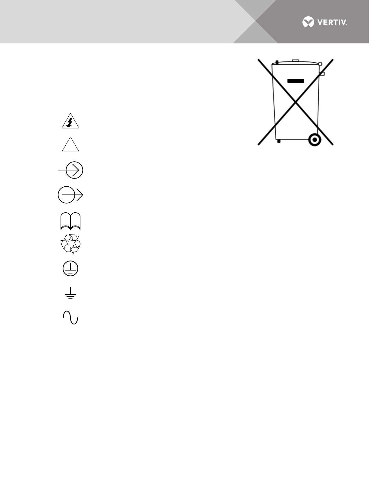
The symbol at right is placed on this product to encourage recycling wherever
!
i
R
possible. Recycle this product through a recycling facility at the end of its service
life. Do not dispose of this product as unsorted municipal waste.
Follow local municipal waste ordinances for proper disposal provisions to reduce
the environmental impact of waste electrical and electronic equipment (WEEE).
Table 1 GLOSSARY OF SYMBOLS
Risk of electrical shock
Indicates caution followed by important instructions
AC input
AC output
Consult the manual
Recycle
Equipment grounding conductor
Bonded to ground
AC voltage
Vertiv | Liebert® ITA2™, 8-10kVA, 208/220V Three-Phase MBC User Manual | Rev. 0 | 02/18 | 3
Page 8
1.0 INTRODUCTION
1
2
1. Plastic Bezel
2. Rear Panel
4
3
5
2
1
The Liebert ITA2 MBC is an option that allows isolating the UPS power module while maintaining power to the
connected load.
This chapter details appearance, components and operation modes of the Liebert ITA2 MBC (maintenance
bypass cabinet). Ta ble 6 details the unit’s specifications.
1.1 Components
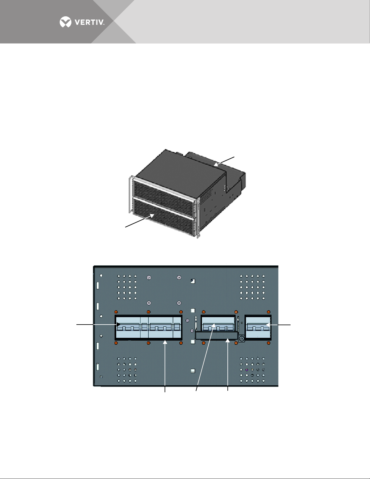
The appearance of the Liebert ITA2 MBC is shown in Figure 1.
Figure 1 Appearance of Liebert ITA2 MBC
Removing the plastic bezel reveals front panel of the Liebert ITA2 MBC, as shown in Figure 2.
Figure 2 Front panel of Liebert ITA2 MBC
1. Rectifier Input Breaker 2. Maintenance Isolation Breaker 3. Maintenance Bypass Breaker Interlock
4. Maintenance Bypass Breaker 5. Bypass Isolation Breaker
Labels not shown.
Figure 3 shows the rear panel of the Liebert ITA2 MBC.
Vertiv | Liebert® ITA2™, 8-10kVA, 208/220V Three-Phase MBC User Manual | Rev. 0 | 02/18 | 4
Page 9

Figure 3 Rear panel of the single POD
3
2
1
1
1
3
6 7 8 9 10 11 12 11 10 9 8 7 6
151413 131415
45
12 12 12
2
1616
1. POD Port Cover 2. Dry Contact Port 3. Cable Entry Knockouts on Conduit Box
Removing the conduit box reveals the Liebert ITA2 MBC’s power distribution area, shown in Figure 4.
Figure 4 Power distribution area of Liebert ITA2 MBC
1. Main Input Terminal Blocks 2. PE: Ground 3. UPS Input Terminal Blocks 4. UPS Output Terminal Blocks
5. Main Output Terminal Blocks 6. rA: Rectifier Input A 7. bA: Bypass Input A 8. rB: Rectifier Input B
9. bB: Bypass Input B 10. rC: Rectifier Input C 11. bC: Bypass Input C 12. N: Neutral
13. A: Output Phase A 14. B: Output Phase B 15. C: Output Phase C 16. N: Neutral
NOTE
Copper shorting bars are factory-linked between rA and bA; rB and bB; rC and bC; and N.
Vertiv | Liebert® ITA2™, 8-10kVA, 208/220V Three-Phase MBC User Manual | Rev. 0 | 02/18 | 5
Page 10
1.2 Operation Modes
1
2
3
4
5
9
7
6
8
1
2
3
4
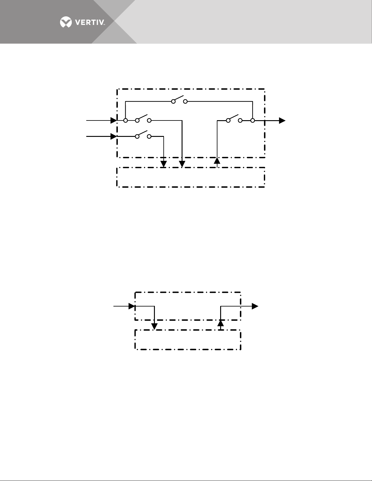
The operating principle of the Liebert ITA2 MBC is shown in Figure 5.
Figure 5 Operating principle of Liebert ITA2 MBC
1. Bypass Input 2. Bypass Isolation Breaker 3. Maintenance Bypass Breaker
4. Maintenance Isolation Breaker 5. Output 6. Liebert ITA2 MBC
7. Rectifier Input Breaker 8. Main Input 9. Liebert ITA2 UPS
Two operation modes are available:
•UPS Mode
• Maintenance Bypass Mode.
1.3 UPS Mode
See Figure 6 for details.
Figure 6 UPS mode
1. AC Input 2. Liebert ITA2 MBC 3. To Load 4. Liebert ITA2 UPS
Under UPS mode, the UPS can provide continuous, high quality AC power.
Vertiv | Liebert® ITA2™, 8-10kVA, 208/220V Three-Phase MBC User Manual | Rev. 0 | 02/18 | 6
Page 11
1.4 Maintenance Bypass Mode
123
4
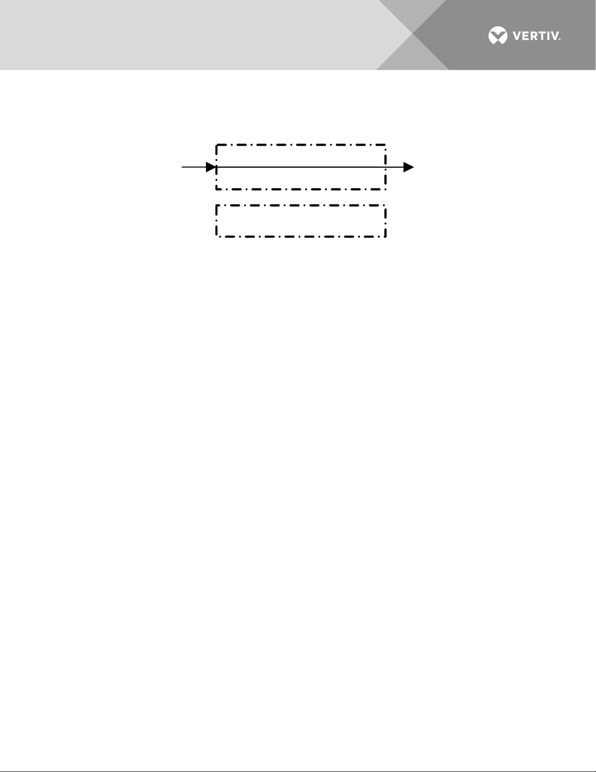
See Figure 7 for details.
Figure 7 Maintenance bypass mode
1. AC Input 2. Liebert ITA2 MBC 3. To Load 4. Liebert ITA2 UPS
In maintenance bypass mode, the UPS is bypassed and the load is powered via the maintenance bypass breaker.
Vertiv | Liebert® ITA2™, 8-10kVA, 208/220V Three-Phase MBC User Manual | Rev. 0 | 02/18 | 7
Page 12
2.0 INSTALLATION AND OPERATION
2
3
1
1
This chapter introduces the mechanical installation, cable connection and commissioning of the Liebert ITA2
MBC.
2.1 Mechanical Installation
NOTE
Only Vertiv-authorized personnel should install and operate the Liebert ITA2 MBC.
The Liebert ITA2 MBC may be installed in either a tower or rack configuration.
Prepare the tools: Phillips screwdriver, adjustable wrench, torque wrench.
2.1.1 Tower Installation
To install the UPS:
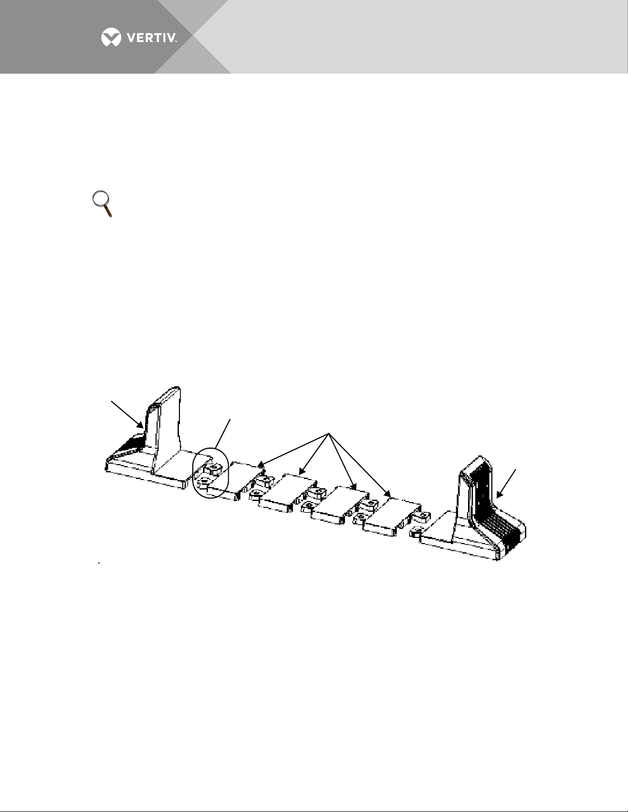
1. Take out the support base extension from the accessories
2. Assemble a pair of support bases and a support base extension (accessory) together through the fastenings, as shown in
Figure 8.
3. Place the assembly where the UPS will be installed.
Figure 8 Connecting the support base with support base extension
1. Support Base 2. Fasteners 3. Support Base Extensions
4. Place the Liebert ITA2 MBC, UPS and battery modules on the support bases and support base extensions, as shown in
Figure 9.
Vertiv | Liebert® ITA2™, 8-10kVA, 208/220V Three-Phase MBC User Manual | Rev. 0 | 02/18 | 8
Page 13
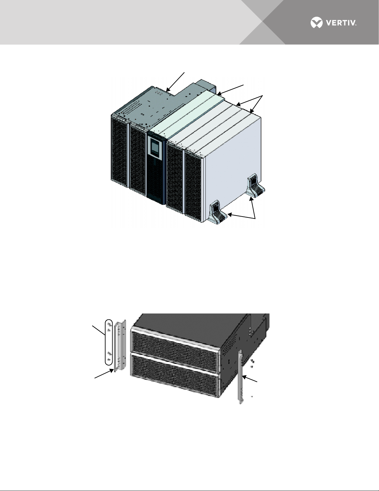
Figure 9 Liebert ITA2 MBC, UPS and battery module Installation complete
1
2
3
4
2
1
2
1. Liebert ITA2 MBC 2. Liebert ITA2 UPS 3. Liebert ITA2 Battery Cabinets, 2 4. Support Base
2.1.2 Rack Installation
NOTICE
Risk of improper transport. Can cause property damage.
Do not lift or carry the Liebert ITA2 UPS or MBC with the brackets. They are intended to support the units in the rack.
Using them to lift the unit may cause them to break.
1. Use M4 × 10 screws (12PCS) to attach two brackets to the Liebert ITA2 MBC front panel, one on each side as shown in
Figure 10.
Figure 10 Installing brackets
1. M4*10 Screws, 12 2. Bracket, 2
2. Install the guide rails.
a. Take out the guide rails (one left guide rail and one right guide rail), guide rail screws and panel screws from the
package.
b. Distinguish the left guide rail and the right guide rail according to Figure 11, and confirm their retractable function.
Vertiv | Liebert® ITA2™, 8-10kVA, 208/220V Three-Phase MBC User Manual | Rev. 0 | 02/18 | 9
Page 14
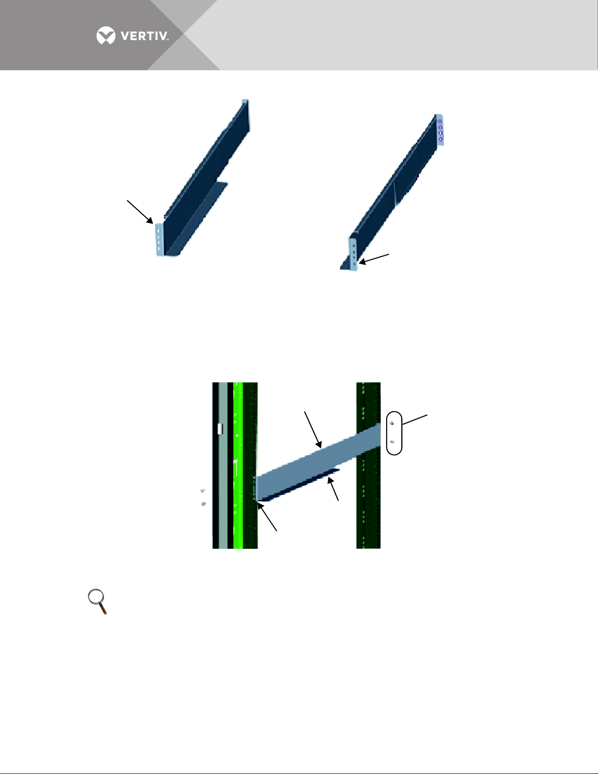
Figure 11 Guide rail orientation for installation
1
2
2
1
3
4
1. Left guide rail 2. Right guide rail
(Flanges point to outside of rack.)
c. Adjust the length of the guide rail based on the dimensions of the rack.
d. Align the installation holes of the guide rail with the square holes of the rack.
e. Attach the guide rail on the rack through the provided guide rail screws.
Eight guide rail screws are provided; each guide rail requires four guide rail screws, as shown in Figure 12.
Figure 12 Installing the left guide rail
1. Guide Rail (left rail shown) 2. Guide Rail Screws, 4, Phillips 3. Guide Rail Base Support 4. Square Holes
NOTE
The guide rail base support must be nearer the front of the rack.
Each end of one guide rail has six installation holes. Vertiv recommends using the top and bottom installation
holes (from top to bottom, installation Hole 1 and installation Hole 4).
Do not use the two installation holes in the middle when attaching the guide rail. The middle holes are intended
to secure the Liebert ITA2 MBC once it is installed on the rack rails.
The guide rail installation is finished, as shown in Figure 13.
Vertiv | Liebert® ITA2™, 8-10kVA, 208/220V Three-Phase MBC User Manual | Rev. 0 | 02/18 | 10
Page 15
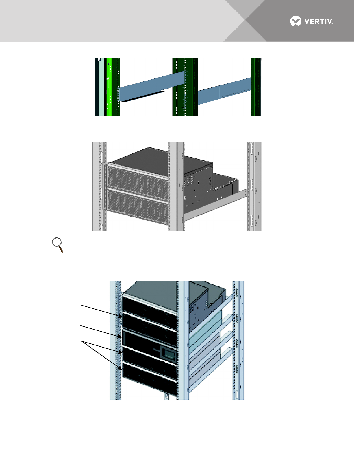
Figure 13 Guide rail installation complete
1
2
3
3. Place the Liebert ITA2 MBC on the guide rails of the rack, and push it completely into the rack.
4. Use four panel screws (M6 × 16) to attach the Liebert ITA2 MBC on the rack through the brackets, as shown in Figure 14.
Figure 14 Installing the Liebert ITA2 MBC
NOTE
When the Liebert ITA2 MBC is installed with battery modules and UPS’s, the battery modules must be installed
at the bottom, the UPS’s in the middle and the Liebert ITA2 MBC at the top to facilitate cable connection and
operation. See Figure 15.
Figure 15 System installation layout—rack
1. Liebert ITA2 MBC 2. Liebert ITA2 UPS 3. Batteries, 2
Vertiv | Liebert® ITA2™, 8-10kVA, 208/220V Three-Phase MBC User Manual | Rev. 0 | 02/18 | 11
Page 16
2.2 Connecting Liebert ITA2 MBC Cables
2.2.1 Selecting Cables
NOTE
Before connecting the cables between the Liebert ITA2 MBC and UPS, make sure that all the circuit breakers on
the Liebert ITA2 MBC front panel are open. Ensure that the feeder breakers are open and locked and tagged to
prevent inadvertent operation by unauthorized personnel.
I/O cables and signal cables are required for connection. When connecting the cables, you should follow the local
wiring regulations, take the environment situation into account.
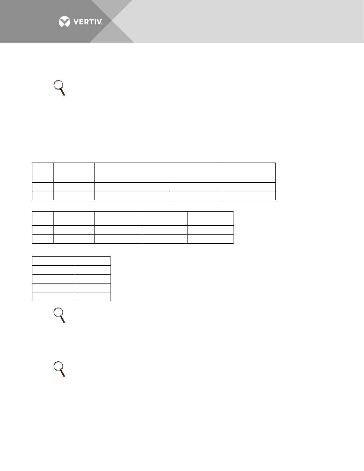
The maximum current in different operating modes and the recommended power cables and plugs are listed in
Tables 2 through 4.
Table 2 Liebert ITA2 MBC currents and cables—User and UPS rectifier input
Unit
Rating
8KVA 24 8AWG 8AWG 10AWG
10KVA 37 6AWG 6AWG 10AWG
Table 3 Liebert ITA2 MBC currents and cables—User and UPS bypass input and output
Unit
Rating
8KVA 23 10AWG 10AWG 10AWG
10KVA 28 8AWG 8AWG 10AWG
Maximum Input
Current, A
Maximum Input
Current (A)
75°C THW Copper
* Number of Cables per Phase: 1
75°C THW Copper
Wire (Phase)
Wire (Phase)
75°C THW Copper
Wire (Neutral)
75°C THW Copper
Wire (Neutral)
* Number of Cables: 1
75°C THW Copper
Wire (Ground)
75°C THW Copper
Wire (Ground)
* Number of Cables: 1
Table 4 Recommended lug sizes
Cable Size, AWG T&B Lug P/N
4RF4-14
6RE6-14
8RD8-14
10 RC10-14
NOTE
The wire size range for Liebert ITA2 MBC terminal blocks: Max. 4AWG, min. 14AWG.
Recommended torque value for phase terminal block: 35 lbf.in of 4-6 AWG; 25 lbf.in of 8 AWG; 20 lbf.in of
10-14AWG; Recommended torque value for neutral and ground busbar: 43 lbf.in.
2.2.2 Connecting Power Cables
NOTE
The terminal blocks use captive screws for connecting phase cables. The neutral cables and ground cable are
attached to the copper bars with captive screws.
2.3 Single-Input Configuration—Factory Default
Remove the conduit box from the Liebert ITA2 MBC and open the knockout hole, route cables through the
conduit, and then connect them to terminal block of the Liebert ITA2 MBC. The conduit size and wiring method
must be in accordance with all local, regional and national codes and regulations, including NEC ANSI/NFPA 70.
Vertiv | Liebert® ITA2™, 8-10kVA, 208/220V Three-Phase MBC User Manual | Rev. 0 | 02/18 | 12
Page 17

2.3.1 Connecting the Main Input Cables-Single Input
Leave the shorting busbars installed on the main input terminals (see Figure 16, Item 1). Make these
connections:
• Input wiring Phase A to the shorting bar between Terminals 6-7
• Phase B to the shorting bar between Terminals 8-9
• Phase C to the shorting bar between Terminals 10-11.
• Input neutral to the shorting bar on Terminal 12
• Ground to the ground (PE) busbar.
2.3.2 Connecting the Main Output Cables-Single Input
The Liebert ITA2 MBC is capable of hardwire output in addition to output through the integrated distribution
ports. If hard wiring to a dedicated output distribution panel (see Figure 16 Item #5), make these connections:
• Phase A to Terminal 13
• Phase B to Terminal 14
• Phase C to Terminal 15
• Output neutral to busbar 16
• Safety ground to the ground (PE) busbar.
2.3.3 Cable Connections from the Liebert ITA2 MBC to the UPS—Single-Input
Single-Input Hardwire Connections—Rectifier Input from MBC
Remove the shorting busbars on the UPS input terminal block on Terminals 11, 12, and 13.
With the shorting busbars removed from the UPS input terminal block, on the MBC unit, refer to Figure 16, Item
#3 and Figure 17; make these connections:
• Phase A cable from MBC Terminal 6 to UPS Terminal 11
• Phase B cable from MBC Terminal 8 to UPS Terminal 13
• Phase C from MBC Terminal 10 to UPS Terminal 15
• Neutral from MBC Terminal 12 to UPS Terminal 17
• Safety ground cable from MBC ground (PE) busbar to UPS Ground Stud 10.
Hardwire Connections—UPS Bypass Input
With the shorting busbars removed on the UPS input terminal block. On the MBC unit, refer to Figure 16 Item #3
and Figure 17; make these connections:
• Phase A cable from MBC Terminal 7 to UPS Terminal 12
• Phase B cable from MBC Terminal 9 to UPS Terminal 14
• Phase C from MBC Terminal 11 to UPS Terminal 16
• Neutral from MBC Terminal 12 to UPS Terminal 18
• Safety ground cable from MBC ground (PE) busbar to UPS Ground Stud 10.
Single-Input Hardwire Connections—UPS Output to MBC
The Liebert ITA2 UPS has two output terminal block sections. One is always On and the other is programmable.
These instructions will list the always-on connections; the programmable connections will be inside parentheses.
On the MBC unit, using Figure 16 Item #4 and Figure 17, make these connections:
•Phase A cable from MBC Terminal 13 to UPS Terminal 4 (9)
• Phase B cable from MBC Terminal 14 to UPS Terminal 3 (8)
• Phase C cable from MBC Terminal 15 to UPS Terminal 2 (7)
• Neutral cable from MBC Terminal 16 to UPS Terminal 5 (6)
• Safety ground cable from MBC ground (PE) busbar to UPS Ground Stud 1.
Vertiv | Liebert® ITA2™, 8-10kVA, 208/220V Three-Phase MBC User Manual | Rev. 0 | 02/18 | 13
Page 18
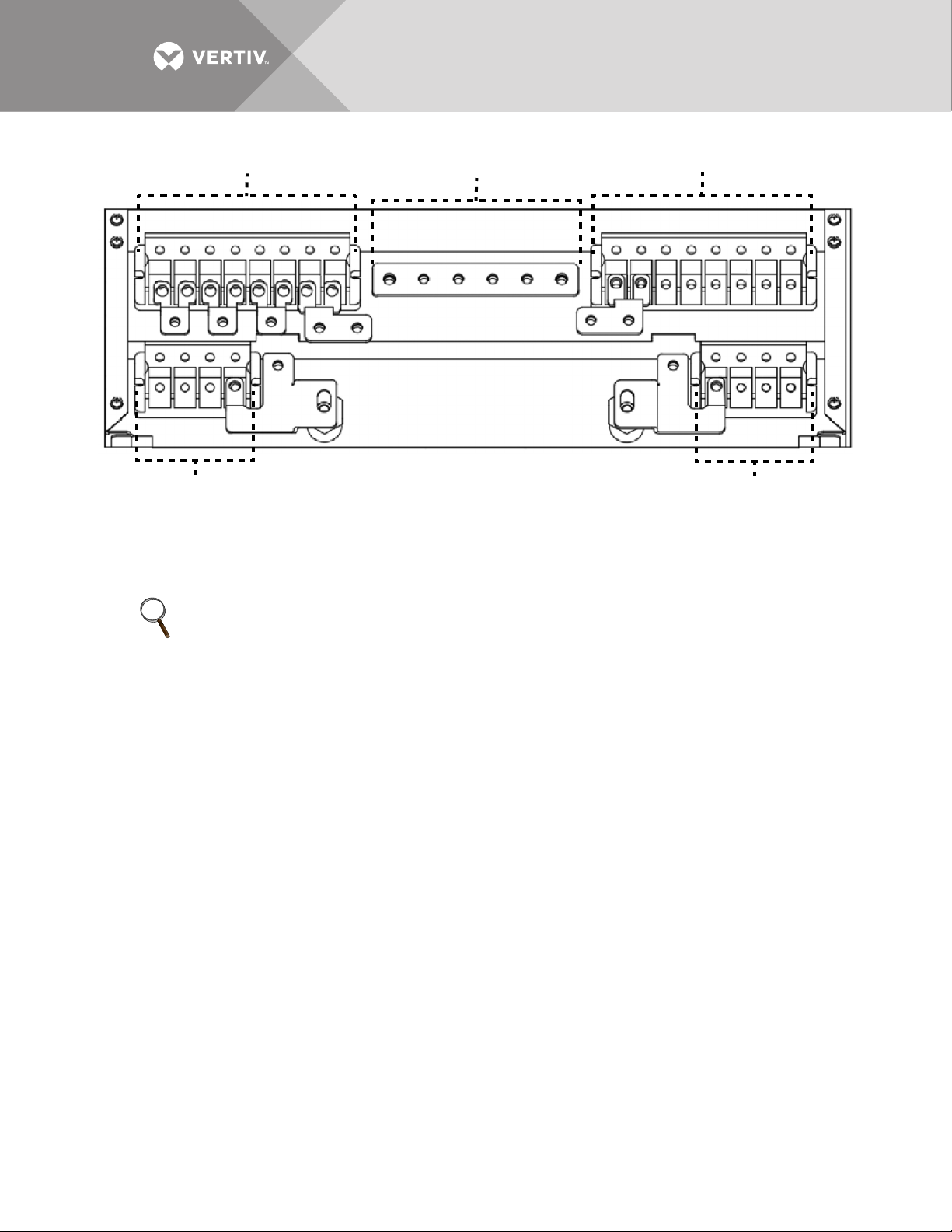
Figure 16 Liebert ITA2 MBC cable connections
1 3
6 7 8 9 10 11 12 11 10 9 8 7 6
151413 131415
45
12 12 12
2
1616
1. Main Input Terminal Blocks 2. PE: Ground 3. UPS Input Terminal Blocks 4. UPS Output Terminal Blocks
5. Main Output Terminal Blocks 6. rA: Rectifier Input A 7. bA: Bypass Input A 8. rB: Rectifier Input B
9. bB: Bypass Input B 10. rC: Rectifier Input C 11. bC: Bypass Input C 12. N: Neutral
13. A: Output Phase A 14. B: Output Phase B 15. C: Output Phase C 16. N: Neutral
NOTE
Copper shorting bars are factory-linked between rA and bA; rB and bB; rC and bC; and N.
2.4 Dual-Input Configuration
Remove the conduit box of Liebert ITA2 MBC and open the knockout hole, route cables through the conduit and
connect them to terminal block of Liebert ITA2 MBC. The conduit size and wiring method must be in accordance
with all local, regional and national codes and regulations, including NEC ANSI/NFPA 70.
2.4.1 Dual-Input Configuration—Main Input
A dual-input Liebert ITA2 UPS requires that both feeds be from the same source. For the main input to the
Liebert ITA2 MBC refer to Figure 16 Item #1, remove the shorting busbars between Terminals 6-7, 8-9 and 10-11.
2.4.2 Dual-Input Configuration—Rectifier Input
Make these connections:
• Input wiring Phase A cable to MBC Terminal 6
• Input wiring Phase B cable to MBC Terminal block 8
• Input wiring Phase C cable to MBC Terminal 10
• Input neutral cable to MBC Terminal 12
• Equipment ground cable to MBC ground (PE) busbar
2.4.3 Dual-Input Configuration—Bypass Input
Make these connections:
• Input bypass wiring Phase A cable to MBC Terminal 7
• Input bypass wiring Phase B cable to MBC Terminal block 9
• Input bypass wiring Phase C cable to MBC Terminal 11
• Input bypass neutral cable to MBC Terminal 12
• Equipment ground cable to MBC ground (PE) busbar
Vertiv | Liebert® ITA2™, 8-10kVA, 208/220V Three-Phase MBC User Manual | Rev. 0 | 02/18 | 14
Page 19

2.4.4 Dual-Input Configuration—Main Output
The Liebert ITA2 MBC is capable of hardwire output in addition to output from the integrated distribution ports.
If hard wiring to a dedicated output distribution panel (see Figure 16 Item #5), make these connections:
• Phase A to terminal 13
• Phase B to terminal 14
• Phase C to terminal 15
• Output neutral to busbar 16
• Safety ground to the ground (PE) bus bar
2.4.5 Cable Connections from the Liebert ITA2 MBC to the UPS—Dual-Input
Hardwire Connections—UPS Rectifier Input
Remove the shorting busbars on the UPS input terminal block on Terminals 11, 12, and 13.
With the shorting busbars removed from the UPS input terminal block, on the MBC unit, refer to Figure 16, Item
#3 and Figure 17; make these connections:
• Phase A cable from MBC Terminal 6 to UPS Terminal 11
• Phase B cable from MBC Terminal 8 to UPS Terminal 13
• Phase C from MBC Terminal 10 to UPS Terminal 15
• Neutral from MBC Terminal 12 to UPS Terminal 17
• Safety ground cable from MBC ground (PE) busbar to UPS Ground Stud 10.
Hardwire Connections—UPS Bypass Input
Leave the shorting busbars in place on the UPS input terminal block. On the MBC unit, refer to Figure 16 Item #3
and Figure 17; make these connections:
• Phase A cable from MBC Terminal 7 to UPS Terminal 12
• Phase B cable from MBC Terminal 9 to UPS Terminal 14
• Phase C from MBC Terminal 11 to UPS Terminal 16
• Neutral from MBC Terminal 12 to UPS Terminal 18
• Safety ground cable from MBC ground (PE) busbar to UPS Ground Stud 10.
Hardwire Connections—UPS Output
The Liebert ITA2 UPS has two output terminal block sections. One is always On and the other is programmable.
These instructions will list the always-on connections; the programmable connections will be inside parentheses.
On the MBC unit, refer to Figure 16 Item #4 and Figure 17; make these connections:
•Phase A cable from MBC Terminal 13 to UPS Terminal 4 (9)
• Phase B cable from MBC Terminal 14 to UPS Terminal 3 (8)
• Phase C cable from MBC Terminal 15 to UPS Terminal 2 (7)
• Neutral cable from MBC Terminal 16 to UPS Terminal 5 (6)
• Safety ground cable from MBC ground (PE) busbar to UPS Ground Stud 1.
Vertiv | Liebert® ITA2™, 8-10kVA, 208/220V Three-Phase MBC User Manual | Rev. 0 | 02/18 | 15
Page 20
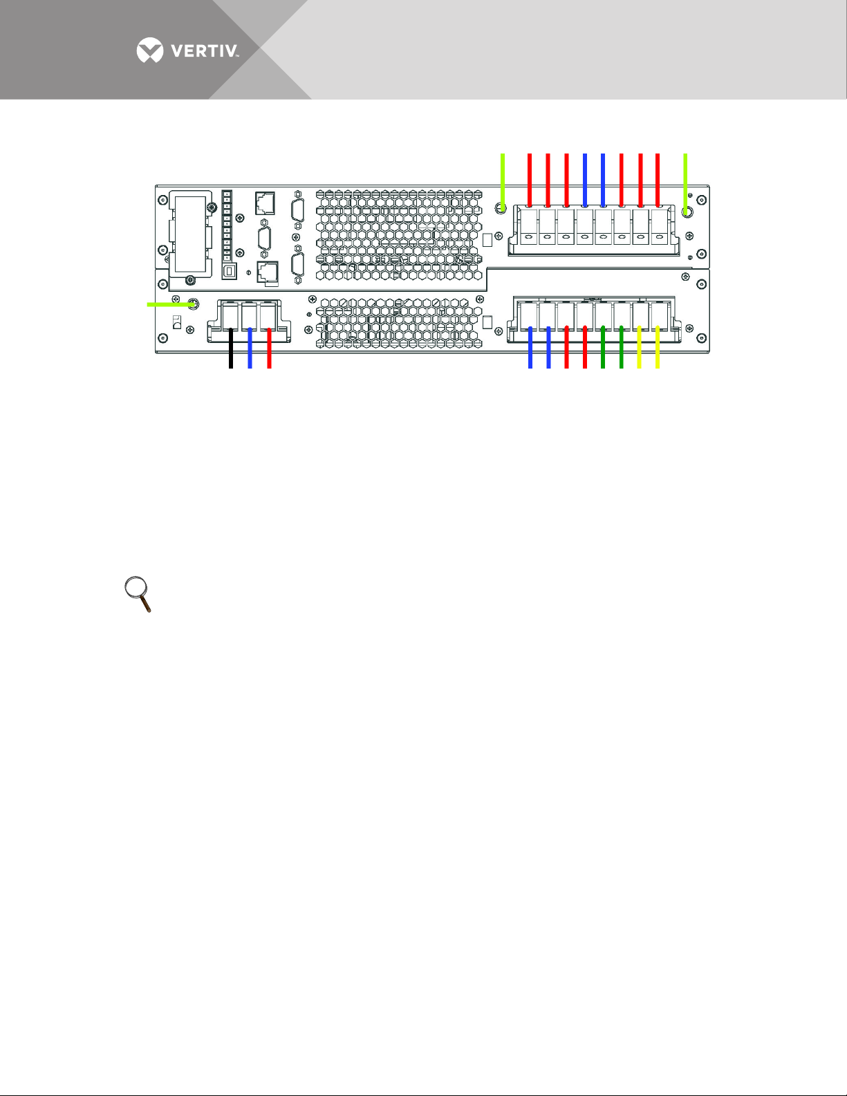
Figure 17 Liebert ITA2 UPS cable connections
12345678910
121316192021 1114151718
22
1. PE: Output PE Terminal 2. C: AC Output Terminal Phase C 3. B: AC Output Terminal Phase B
4. A: AC Output Terminal Phase A 5. N: Output Neutral Line Terminal 6. N: Output Neutral Line Terminal
7. pC: Programmable AC Output
Terminal Phase C
10. PE: Input PE Terminal. 11. rA: AC Rectifier Input Phase A 12. bA: Bypass Input Phase A
13. rB: AC Rectifier Input Phase B 14. bB: Bypass Input Phase B 15. rC: AC Rectifier Input Phase C
16. bC: Bypass Input Phase C 17. N: Output Neutral Line Terminal 18. N: Output Neutral Line Terminal
19. BAT+: Battery Positive Terminal 20. BATN: Battery Neutral Terminal 21. BAT-: Battery Negative Terminal
22. Battery PE Terminal
8. pB: Programmable AC Output Terminal Phase B 9. pA: Programmable AC Output
Terminal Phase A
NOTE
All the copper jumper bars relating to the procedures above are accessories.
Vertiv | Liebert® ITA2™, 8-10kVA, 208/220V Three-Phase MBC User Manual | Rev. 0 | 02/18 | 16
Page 21
2.5 Connect the Communication Cables
1
2
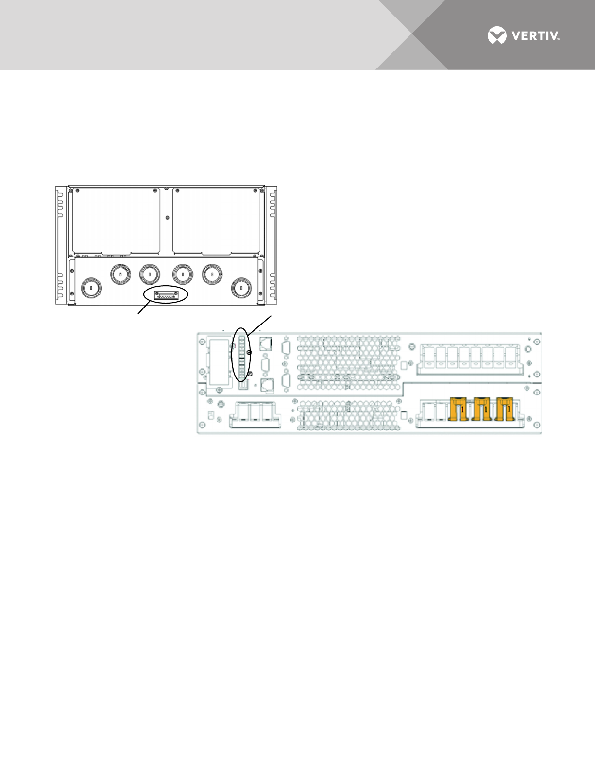
The signal cables are intended for connecting between Liebert ITA2 MBC dry contact ports and UPS dry contact
ports. One end of the signal cable is a terminal of six-pin, and the other end is two-pin.
1. Insert the 6-pin connector to the Liebert ITA2 MBC dry contact port.
2. Insert the three two-pin connectors into the UPS dry contact ports (1, 2, 3) based on cable label. As shown in Figure 18.
Figure 18 Dry contact ports on Liebert ITA2 MBC and UPS
1. Liebert ITA2 MBC Dry Contact port
For 6-Pin Connector
2. Liebert ITA2 UPS Dry Contact Port, 1-4
Vertiv | Liebert® ITA2™, 8-10kVA, 208/220V Three-Phase MBC User Manual | Rev. 0 | 02/18 | 17
Page 22
3.0 POD ASSEMBLY
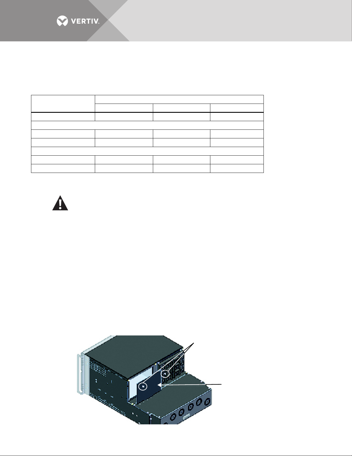
2
1
1. Screws securing POD Cover Panel
2. Liebert ITA2 POD Cover Panel
The power output distribution unit (POD) is an option that may be installed on the Liebert ITA2 MBC to provide
integral power distribution.
Table 5 POD specifications
Model
Item
Dimensions, WxH, in. (mm) 7.4x5.7 (188x145) 7.4x5.7 (188x145) 7.4x5.7 (188x145)
Weight
Net, lb. (kg) 4.1 (1.86) 7.2 (3.28) 6.1 (2.78)
Shipping, lb. (kg) 7.3 (3.32) 10.4 (4.74) 9.3 (4.24)
Electrical Specifications
Rated Current, A 30A, 3P breaker 30A, 2P breaker 30A, 1P breaker
Outlets L21-30R (Number: 2) L6-30R (Number: 6) L5-30R (Number: 6)
PD3-001 PD3-002 PD3-003
3.1 Installing the POD
WARNING
Risk of electric shock. Can cause injury or death.
Failure to shutdown the Liebert ITA2 and to isolate the system electrically means that the system will
contain deadly high voltage within the unit and at its output terminals.
The Liebert ITA2 must be shut down and all local and remote electric input power must be disconnected
before any work may be done on or in the UPS and MBC. This includes the addition, removal or alteration
of a power distribution box.
NOTICE
Risk of improper shutdown. Can cause damage to connected equipment.
Shutting down the UPS system will result in loss of input power to the connected load. Before beginning, shut down the
connected equipment or transfer them to an alternate input power supply. Refer to 4.2 - Shutdown for details about
shutting down the Liebert ITA2 UPS.
To install the POD:
1. Remove the screws attaching the POD port cover panel and retain them for reassembly; see Figure 19.
2. Remove the POD port cover and set aside.
3. Align the POD connectors with those inside the POD port, making sure the colors match; see Figure 20..
Figure 19 Removing POD cover panel
Vertiv | Liebert® ITA2™, 8-10kVA, 208/220V Three-Phase MBC User Manual | Rev. 0 | 02/18 | 18
Page 23
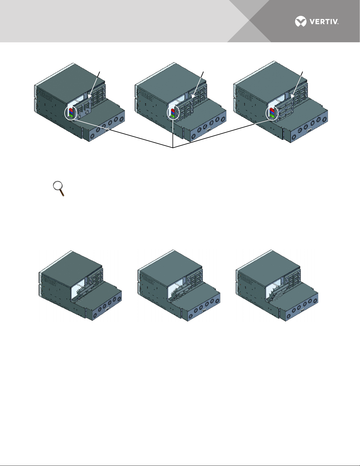
Figure 20 Connecting PP75 terminals
1
2
3
4
1. PP75 Connectors on POD 2. PD103-001 3. PD103-002 4. PD103-003
NOTE
The color of the PP75 terminals on both the POD and the Liebert ITA2 MBC must match exactly.
4. Verify that the connectors are fully seated.
5. Tilt the top of the POD and insert the lower edge into the slot of the POD port on the Liebert ITA2 MBC.
6. Press the top of the POD toward the enclosure and press it into place. See Figure 21.
7. Attach the POD with the screws removed in Step 1.
Figure 21 Angle the POD for installation
Vertiv | Liebert® ITA2™, 8-10kVA, 208/220V Three-Phase MBC User Manual | Rev. 0 | 02/18 | 19
Page 24
4.0 OPERATING THE LIEBERT ITA2 MBC
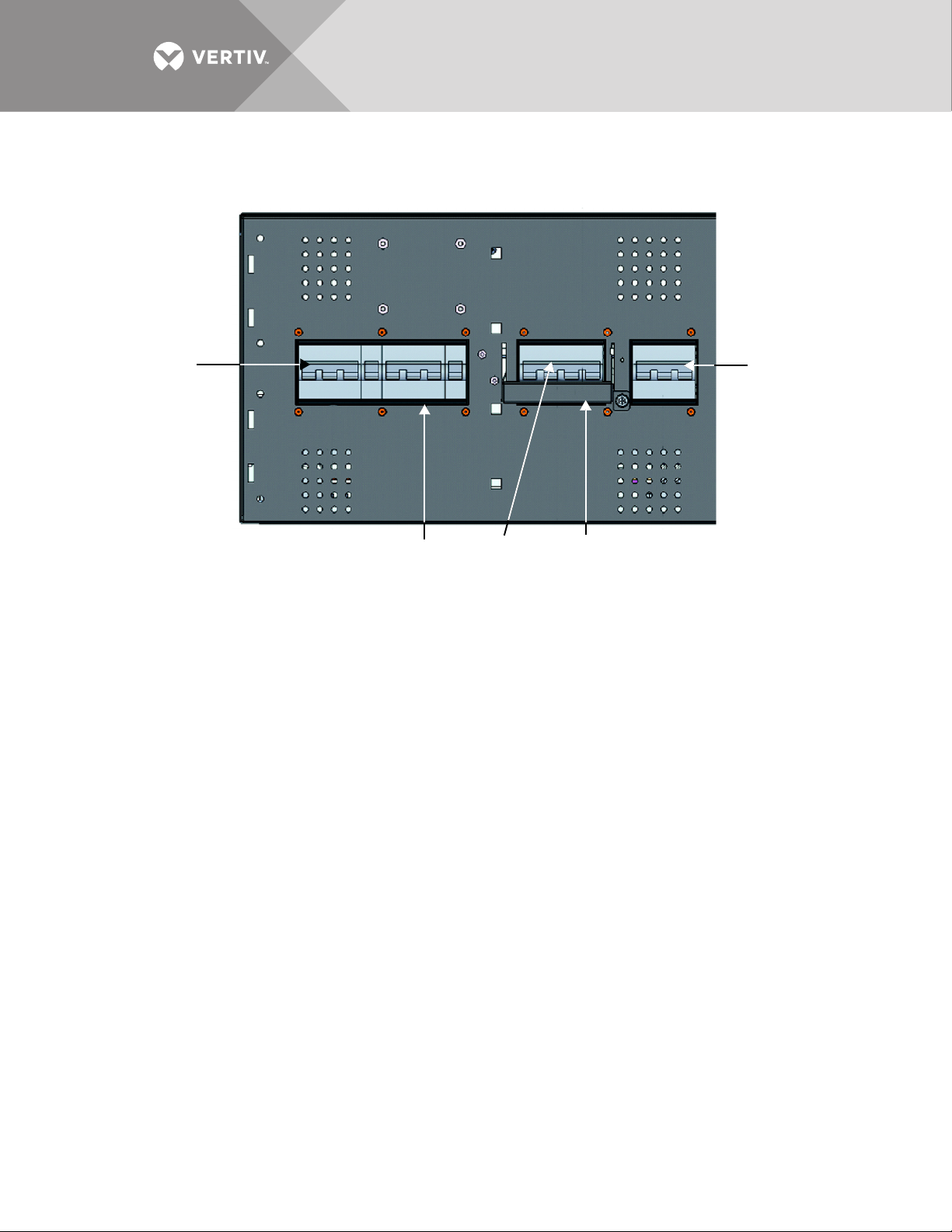
4
3
5
2
1
Figure 22 Front panel of Liebert ITA2 MBC
1. Rectifier Input Breaker 2. Maintenance Isolation Breaker 3. Maintenance Bypass Breaker Interlock
4. Maintenance Bypass Breaker 5. Bypass Isolation Breaker
Labels on UPS not shown.
4.1 Startup
1. If the two plastic bezel are attached to the Liebert ITA2 MBC, remove them by pulling both ends toward you with equal
force.
2. Verify that the Maintenance Bypass Breaker on the front of the Liebert ITA2 MBC is Off (open) and that the breaker
interlock is secured in place.
3. Close the feeder breakers in the external panel to provide main input and bypass input (for dual input system).
4. On the front of the Liebert ITA2 MBC, close the rectifier input breaker, bypass isolation breaker and maintenance isolation
breaker.
5. If any optional POD’s are installed, verify that any distribution breakers on the POD’s are closed.
6. Start the UPS according to procedures in the UPS user manual, SL-00030.
The connected equipment should now be supplied protected power from the UPS.
7. Reinstall the two plastic bezels on the front of the Liebert ITA2 MBC.
4.2 Shutdown
NOTICE
Risk of improper shutdown. Can cause damage to the connected equipment.
Shutting down the Liebert ITA2 will disconnect input power to the connected equipment. Before shutting down the UPS,
prepare the connected equipment, either by transferring it to an alternate input power source or shutting it down.
If shutting down the Liebert ITA2 UPS is an emergency, either operate the REPO button, if installed, or remove
the four-pin connector on the rear of the UPS for communication terminal block Pins 9-12.
To shut down the Liebert ITA2 UPS to take it out of service, follow the procedures in the UPS user manual. Once
the UPS has been shutdown, remove the plastic bezel from the front of the MBC to reveal the circuit breakers.
Open all circuit breakers to electrically isolate the UPS unit from input power.
Vertiv | Liebert® ITA2™, 8-10kVA, 208/220V Three-Phase MBC User Manual | Rev. 0 | 02/18 | 20
Page 25

4.3 Transfer UPS from Normal Mode to Maintenance Bypass Mode
1. Remove the two plastic bezels from the front of the Liebert ITA2 MBC by pulling both ends toward you with equal force.
2. Transfer the Liebert ITA2 UPS to internal bypass by following the procedures in the UPS user manual, SL-00030.
3. Loosen the thumb screw on the interlock on the Maintenance Bypass Breaker.
4. Slide the interlock up (rack-mount orientation) or to the side (tower orientation) and tighten the thumb screw to secure
the interlock in place.
NOTE
When the interlock is moved to unlock the maintenance bypass breaker, the UPS will transfer to internal bypass
if it was not already done in Step 2. The connected equipment is now unprotected from power abnormalities.
5. Close the Maintenance Bypass Breaker
6. Open the Rectifier Input Breaker, Bypass Isolation Breaker and Maintenance Isolation Breaker to electrically isolate the
UPS module from AC power
7. Open all battery breakers on the rear of each battery cabinet to electrically isolate the UPS module from DC power.
The system is now in maintenance bypass mode to allow the UPS module to be safely serviced.
4.4 Transfer UPS from Maintenance Bypass Mode to Normal Mode
1. Ensure that the mechanical interlock is still secured in the unlocked position.
2. Close the Rectifier Input Breaker, Bypass Isolation Breaker and Maintenance Isolation Breaker on the front of the MBC.
3. The UPS will begin its startup procedure and operate in internal bypass mode. Verify that the UPS is operating in internal
bypass mode before proceeding.
NOTICE
Risk of improper operation. Can cause damage to the connected load.
Failure to have the UPS operating on internal bypass and performing the next step will result in loss of all output power to
the connected equipment.
4. Open the Maintenance Bypass Breaker
5. Loosen the thumb screw on the mechanical interlock and slide it down (rack orientation) or to the side (tower orientation)
and secure it in place by tightening the thumb screw
6. Transfer the UPS from internal bypass to inverter power following the procedures in the UPS user manual, SL-00030.
The UPS is now in normal operation, and the connected equipment is supplied with protected power.
Vertiv | Liebert® ITA2™, 8-10kVA, 208/220V Three-Phase MBC User Manual | Rev. 0 | 02/18 | 21
Page 26

5.0 SPECIFICATIONS
Table 6 Liebert ITA2 MBC specifications
Liebert ITA2 MBC Model
Item
Dimensions, W x D x H, in. (mm)
Unpacked 16.9 x 22.4x 10.3 (430 x 570x 261 )
Shipping 26 x 30 x 13.7 (662 x 762 x 350)
Weight, lb. (kg)
Net Weight 39.7 (18.02)
Shipping Weight 59.5 (27)
Electrical Parameters
Rating, A 30 40
Voltage 208/120 or 220/127 VAC, 3 Phase 4W+G
Connections Hard Wired
Environmental Conditions
Operating temperature, °F (°C) 32-122° (0° ~ 50°) (0.7 will be derated at 122° [50°])
Relative Humidity 5%RH ~ 95%RH, non-condensing
Altitude, ft. (m) ≤9840 (≤3000)
Maximum Storage and Transportation Temperature, °F (°C) 104 ~ 158 (40~70)
Agency/Standards ISTA Procedure 1A
Safety Standards UL 1778-5th Edition, CSA C22.2 No. 107.3-14
8kVA—ITA2-08kMBC40 10kVA—ITA-10kMBC40
Table 7 Hazardous substances in Liebert ITA2 8kVA 208V and 10kVA 208V Liebert ITA2 MBC
Hazardous Substances
Part
Cables X ✔✔ ✔ ✔ ✔
This table is made following the regulation of SJ/T 11364.
✔: Means the content of the hazardous substances in all the average quality materials of the parts is within the limits specified in GB/T 26572
X: Means the content of the hazardous sustances in at least one of the average quality materials of the parts is outside the limits specified in GB/T 26572
Lead, Pb Mercury, Hg Cadmium, Cd
Hexavalent
Chromium, Cr, VI
Polybrominated
Biphenyl, PBB
Polybrominated
diphenyl ethers, PBDE
Vertiv | Liebert® ITA2™, 8-10kVA, 208/220V Three-Phase MBC User Manual | Rev. 0 | 02/18 | 22
Page 27

TECHNICAL SUPPORT / SERVICE
Web Site
www.vertivco.com
Monitoring
800-222-5877
Outside North America: +00800 1155 4499
Three-Phase UPS & Power Systems
800-543-2378
Outside North America: 614-841-6598
LOCATIONS
United States
1050 Dearborn Drive
P.O. Box 2 9 1 8 6
Columbus, OH 43085
Europe
Via Leonardo Da Vinci 8
Zona Industriale Tognana
35028 Piove Di Sacco (PD) Italy
+39 049 9719 111
Fax: +39 049 5841 257
Asia
29/F, The Orient Square Building
F. Ortigas Jr. Road, Ortigas Center
Pasig City 1605
Philippines
+63 2 687 6615
Fax: +63 2 730 9572
Page 28

VertivCo.com | Vertiv Headquarters, 1050 Dearborn Drive, Columbus, OH, 43085, USA
© 2018 Vertiv Co. All rights reserved. Vertiv and the Vertiv logo are trademarks or registered trademarks of Vertiv Co. All other names and logos referred to are trade names, trademarks or registered trademarks of their respective owners.
While every precaution has been taken to ensure accuracy and completeness herein, Vertiv Co. assumes no responsibility, and disclaims all liability, for damages resulting from use of this information or for any errors or omissions. Specifications are subject to
change without notice.
This document may contain confidential and/or proprietary information of Liebert Corporation, and its receipt or possession does not convey any right to reproduce, disclose its contents, or to manufacture or sell anything that it may describe. Reproduction,
disclosure, or use without specific authorization from Liebert Corporation is strictly prohibited.
SL-26252_REV0_02/18
 Loading...