

Page 1

Liebert® Maintenance Bypass
Cabinet
Installer/User Guide
Page 2

Technical Support Site
If you encounter any installation or operational issues with your product, check the pertinent section of
this manual to see if the issue can be resolved by following outlined procedures. For additional assistance,
visit https://www.VertivCo.com/en-us/support/
Page 3

TABLE OF CONTENTS
1 Important Safety Instructions 5
2 General Description 7
2.1 System Description 7
2.1.1 Features 7
2.1.2 Standard Components 7
2.1.3 Options 7
3 Modes of Operation 11
3.1 UPS Mode 11
3.2 Bypass Mode 11
4 Major Components 13
4.1 Bypass Switch 13
4.2 User Selectable Output Distribution 13
4.2.1 Optional Transformer 13
5 Preparation 15
5.1 Inspection 15
5.2 Environment 15
5.3 Required Setup Equipment 15
5.4 Site Preparation 15
6 Unloading 17
6.1 Unloading the Maintenance Bypass Cabinet 17
6.2 Stationary Mounting 18
7 Cable Installation 21
7.1 Wiring Preparation 21
7.2 Preparing Internal Wiring 21
7.3 Dual Source Configuration 21
7.4 Removing the Cover Plates 23
7.5 REPO Connection 23
7.6 Input and Output Wiring 23
8 Operation 29
8.1 Start-Up and Initialization 29
8.2 Shutting Down the UPS 29
8.3 Transferring the System fromUPStoMaintenanceBypassOperation 30
8.4 Transferring the System fromMaintenanceBypasstoUPSOperation 30
9 Maintenance 31
9.1 Proper Care 31
9.2 Scheduled Maintenance 31
9.2.1 Replacing Fan Filters—Transformer Models Only 31
10 Specifications 33
Vertiv | Liebert® Maintenance Bypass Cabinet Installer/User Guide | 3
Page 4

Vertiv | Liebert® Maintenance Bypass Cabinet Installer/User Guide | 4
Page 5
1 IMPORTANT SAFETY INSTRUCTIONS
SAVE THESE INSTRUCTIONS
This manual contains important instructions that should be closely followed during installation and
maintenance of this Maintenance Bypass Cabinet.
This product is designed for commercial/industrial use only. This product is not intended for use with life
support and other designated “critical” devices. Maximum load must not exceed that shown on the UPS
and the Maintenance Bypass Cabinet rating label.
WARNING! Lethal voltages may be present within this unit even when it is apparently not
operating. Observe all cautions and warnings in this manual. Failure to do so may result in
serious injury or death. Never work alone.
The Liebert Maintenance Bypass Cabinet is designed for use on properly grounded (earthed)
208/240VAC, 60Hz supply, for installation by qualified personnel. This UPS equipment is intended to be
installed by a qualified / certified electrician who must review and approve customer supplied wiring,
circuit breakers, intended loads and verify correct input, output and grounded (earthed) connections to
ensure compliance with technical standards and national and local electrical codes. Installation
instructions and warning notices are located in the Installation section of this manual.
WARNING! To reduce the risk of fire:
The NMB1x and NMB4x models must be connected to a circuit provided with 100 amperes
maximum branch circuit overcurrent protection in accordance with applicable national and local
electrical codes.
The NMB5x and NMB8x models must be connected to a circuit provided with 125 amperes
maximum branch circuit overcurrent protection in accordance with applicable national and local
electrical codes.
Operate the UPS equipment in an indoor environment only in an ambient temperature range of 32°F to
104°F (0°C to 40°C). Install it in a clean environment, free from conductive contaminants, moisture,
flammable liquids, gases, or corrosive substances.
Never block or insert any object into the ventilation holes or other openings.
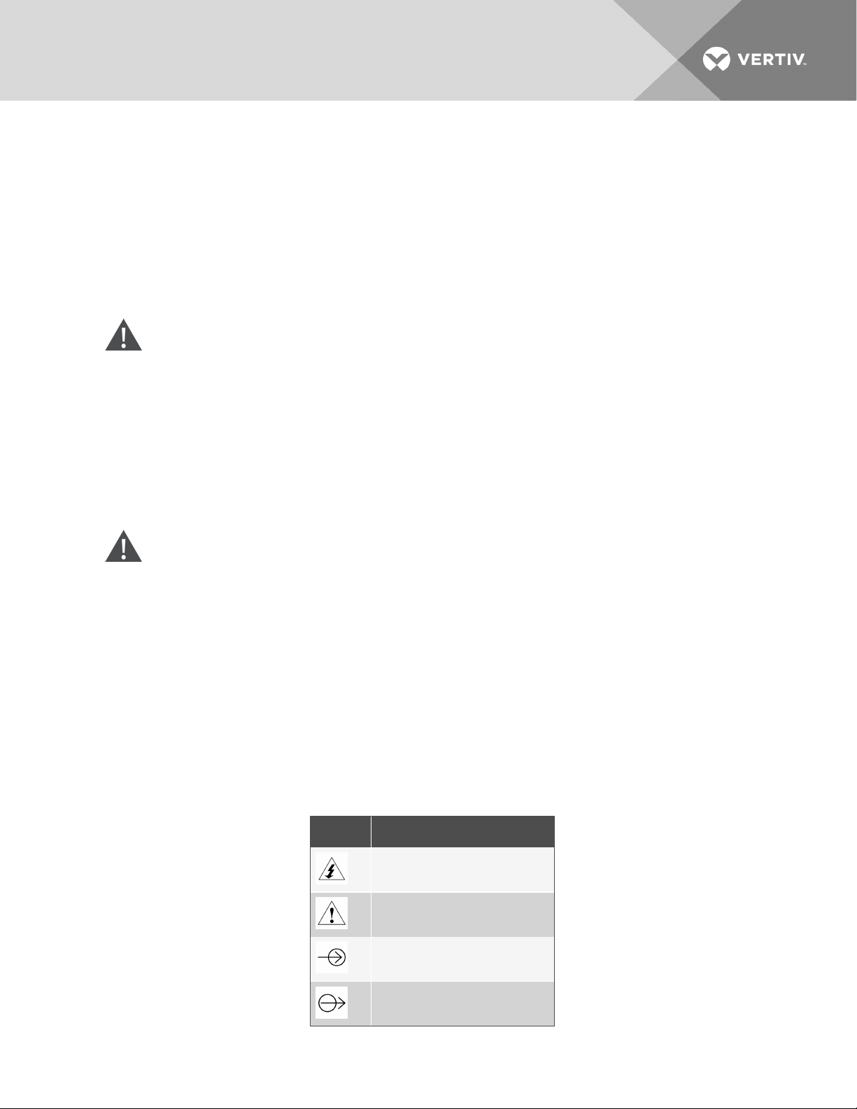
Table 1.1 Glossary of Symbols
SYMBOL DESCRIPTION
Risk ofElectrical Shock
Indicates Warningor Caution
Followed by ImportantInstructions
AC Input
AC Output
Vertiv | Liebert® Maintenance Bypass Cabinet Installer/User Guide | 5
Page 6
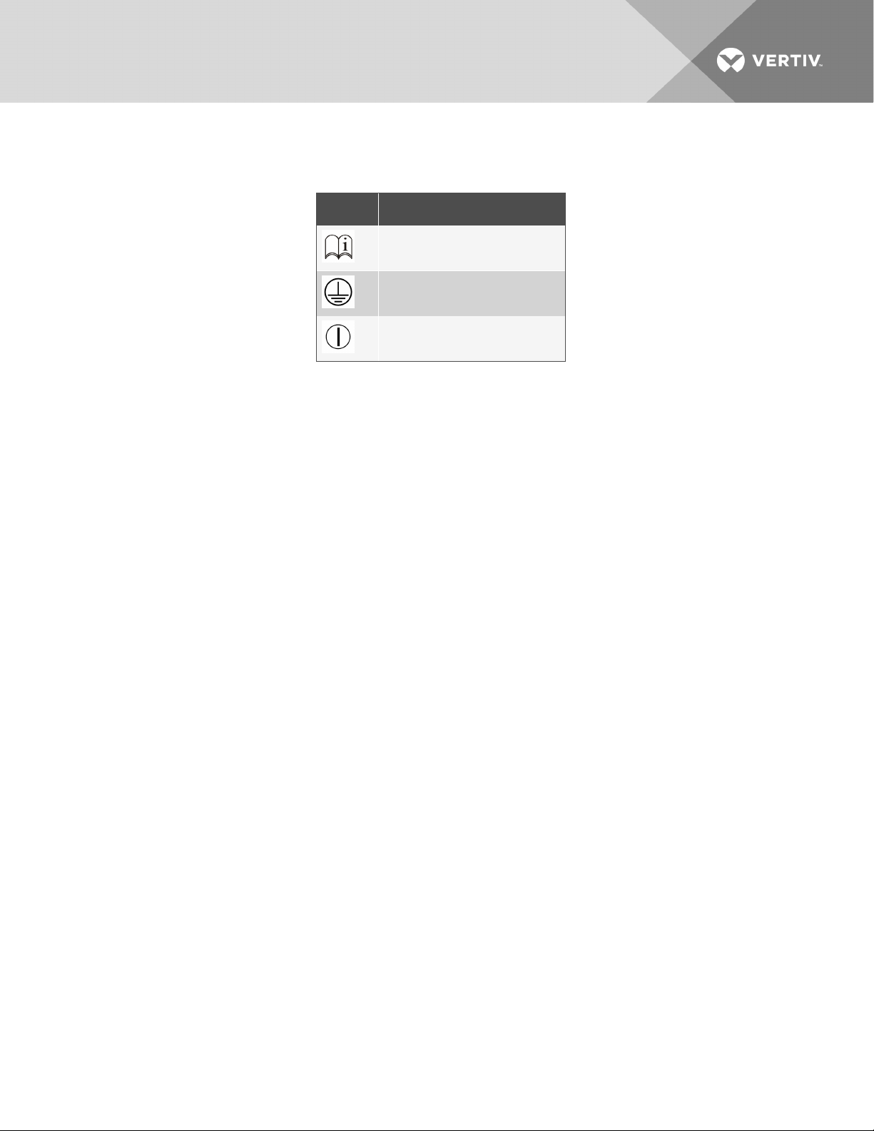
Table 1.1 Glossary of Symbols (con-
tinued)
SYMBOL DESCRIPTION
Requests the user to consult the manual
Equipment Gr oundingConductor
On/Off
Vertiv | Liebert® Maintenance Bypass Cabinet Installer/User Guide | 6
Page 7

2 GENERAL DESCRIPTION
Congratulations on your purchase of Liebert’s Maintenance Bypass Cabinet with Configurable Output
Distribution. As with every Vertiv™ product, we stand behind our quality. If you have any questions
concerning this Maintenance Bypass Cabinet, please feel free to contact your local dealer, Vertiv™
representative, or call Technical Support at 1-800-222-5877.
To ensure proper installation and operation of this unit, please read this manual thoroughly.
Installation must be done by a qualified/certified electrician, but general operation may be performed
without special training.
2.1 System Description
The Liebert Maintenance Bypass Cabinet is intended for use with the Liebert UPS units. Typical
applications include supporting workstations, servers, network, telecom or other sensitive electronic
equipment.
The Maintenance Bypass Cabinet was designed to provide maximum system availability to business
critical equipment. The Maintenance Bypass Cabinet allows for transfer of connected loads to an
alternate power path allowing full isolation of the UPS. The UPS can then be turned “OFF” and removed
from service with no interruption of power to connected loads.
2.1.1 Features
• Supports up to 20 kVA loads
• High speed transfer switch
• Compact design
• Highly configurable
• Multiple power path indicators
2.1.2 Standard Components
• Casters and leveling feet
• Easily accessible terminal blocks
• Supports Lockout/Tagout Program
• Support/mounting brackets for additional stability
• Provisions for hardwire output
• Dual-sourcecompatibleforincreased availability
2.1.3 Options
• Output transformer for isolation
• Field-installable output distribution
Vertiv | Liebert® Maintenance Bypass Cabinet Installer/User Guide | 7
Page 8
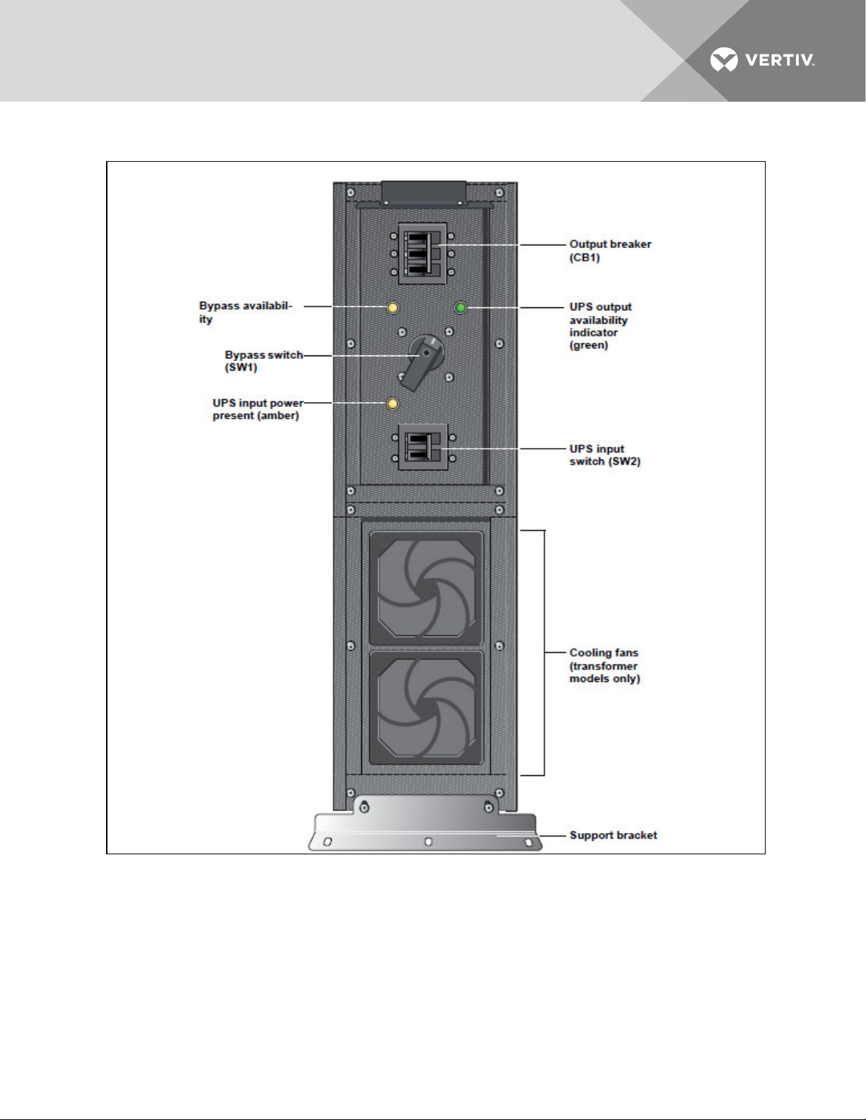
Figure 2.1 Front view
Vertiv | Liebert® Maintenance Bypass Cabinet Installer/User Guide | 8
Page 9
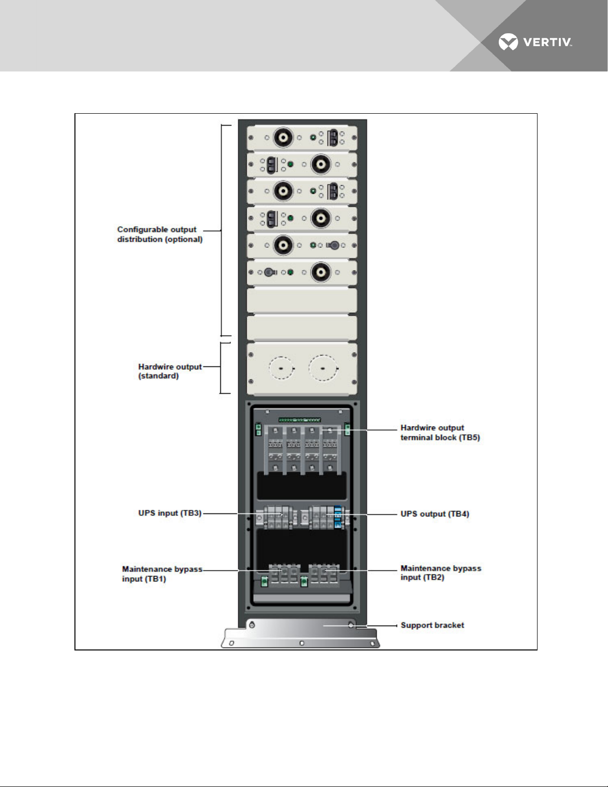
Figure 2.2 Rear view (without transformer)
Vertiv | Liebert® Maintenance Bypass Cabinet Installer/User Guide | 9
Page 10
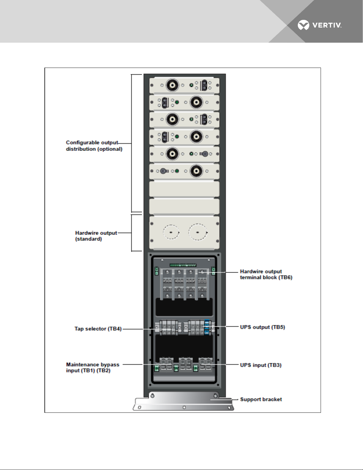
Figure 2.3 Rear view (with transformer)
Vertiv | Liebert® Maintenance Bypass Cabinet Installer/User Guide | 10
Page 11
3 MODES OF OPERATION
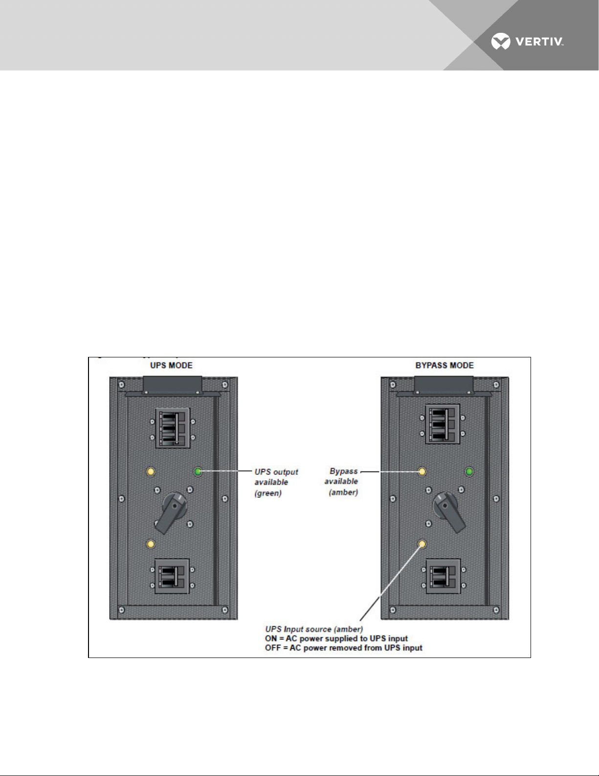
The Maintenance Bypass Cabinet is designed to operate in two modes: UPS Mode and Bypass Mode.
3.1 UPS Mode
While the Maintenance Bypass Cabinet is in UPS Mode, the UPS is supplying the connected load with
continuous, high quality AC power. In this mode of operation, the load is protected by the UPS. The Bypass
Switch rotated toward the green lamp indicates this mode.
3.2 Bypass Mode
When the Maintenance Bypass Cabinet is in the Bypass Mode, it provides an alternate path for power to
the connected equipment. Should the UPS need to be taken out of service for limited maintenance or
repair, manual activation of the bypass will cause an immediate transfer of the equipment from the UPS
inverter to the bypass source.
The amber lamp illuminated in the Maintenance Bypass Switch compartment indicates bypass is
available. In this mode of operation the load is NOT protected by the UPS. The Bypass Switch rotated
toward the amber lamp indicates this mode. See Operation on page29 for instructions on use.
Figure 3.1 Bypass operation modes
Vertiv | Liebert® Maintenance Bypass Cabinet Installer/User Guide | 11
Page 12

This page intentionally left blank.
Vertiv | Liebert® Maintenance Bypass Cabinet Installer/User Guide | 12
Page 13
4 MAJOR COMPONENTS
The following is a general description of each component and its functions. Please review this section
carefully, as it will give you a better understanding as to how the Maintenance Bypass Cabinet operates.
4.1 Bypass Switch
The Bypass Switch allows easy and rapid transfer of connected loads between the UPS and Bypass
source.
4.2 User Selectable Output Distribution
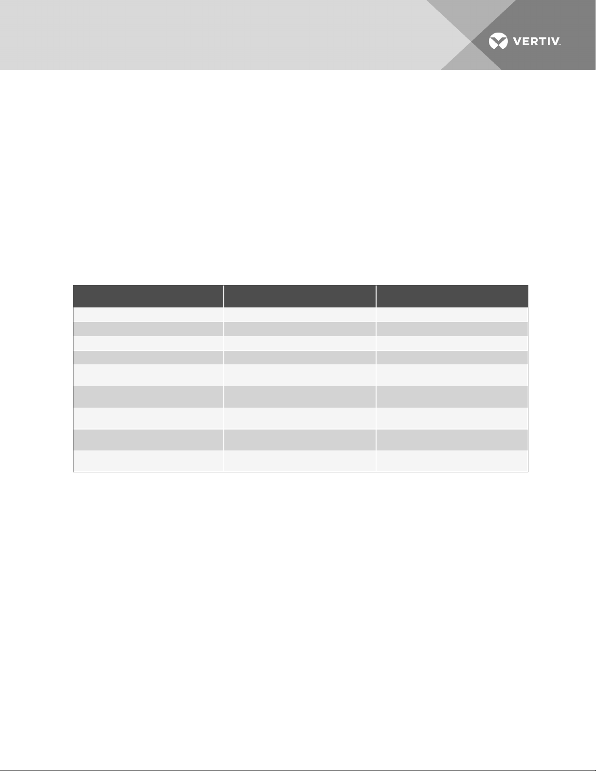
Several receptacle and hardwire options are available as user selectable output distribution. These are
factory configured when ordered and also allow for field upgrades.
Table 4.1 Common receptacle and hardwire options
15 AMP OPTIONS 20 AMP OPTIONS 30 A MP OPTIONS
5-15R2 5-20R2 (T-slot) L5-30R
L5-1 5R2 L5-20R L6-30R-208
6-15R2-208 L6-20R-208 L6-30R-240
6-15R2-24 0 L6-20R-24 0 L14-30R-240
L6-15R2-208 L14-20R-240
L6-15R2-240
15A,120V, 1 pole breaker w/ 1/2" & 3/ 4"
knockouts
15A,208V, 2 pole breaker w/ 1/2" & 3/ 4"
knockouts
15A,240V, 2 pole breaker w/ 1/2" & 3/4"
knockouts
20A,120V, 1 pole breaker w/ 1/2" & 3/4 "
knockouts
20A,208V, 2 pole breaker w/ 1/2" & 3/4"
knockouts
20A,24 0V, 2 pole breaker w/ 1/2" &3/4"
knockouts
30A,120V, 1 pole breaker w/ 1/2" & 3/4 "
knockouts
30A,208V, 2 pole breaker w/ 1/2" & 3/4"
knockouts
30A,24 0V, 2 pole breaker w/ 1/2" & 3/4"
knockouts
Other Options
• Single Position Blanking Plate
• Hardwire Option
4.2.1 Optional Transformer
Models offering a transformer are designed to accept the same input voltage as the UPS and provide 240
/ 208 / 120 / 120 output. Models with transformers are provided with redundant cooling fans and user
serviceable fan filters. The fans operate only when the system is in Bypass mode.
Vertiv | Liebert® Maintenance Bypass Cabinet Installer/User Guide | 13
Page 14

This page intentionally left blank.
Vertiv | Liebert® Maintenance Bypass Cabinet Installer/User Guide | 14
Page 15

5 PREPARATION
These installation instructions provide all the information needed for positioning the Maintenance Bypass
Cabinet (including environmental requirements) and for connecting the input and output power cables.
5.1 Inspection
Upon receiving the Maintenance Bypass Cabinet, examine the packaging for any signs of mishandling or
damage. If any damage is noted, contact your local dealer or Vertiv™ representative and notify your
carrier.
5.2 Environment
The Maintenance Bypass Cabinet environment must be free of conductive contaminants and excessive
moisture (water condensation), flammable vapors, chemical fumes, or corrosive gases and liquids.
5.3 Required Setup Equipment
The tools below are required in order to properly set up your Maintenance Bypass Cabinet:
• pallet jack
• 1/2" (13 mm) wrench
• torque wrench
• flat-head screwdriver
• #2 Phillips screwdriver
• 3/16" (5 mm) Allen wrench
5.4 Site Preparation
When deciding where to locate your Maintenance Bypass Cabinet, consider the weight and size of the
unit. Make sure that the structural integrity of the floor can withstand the weight. Refer to the table below
for dimensional considerations:
Table 5.1 Maintenance Bypass
Cabinet physical data
DIMENSIONS
Model With Transformer Without Transformer
W x D x H
In (mm)
Weight 287 lb (130 kg) 85 lb (38 kg)
Check to make sure that your Maintenance Bypass Cabinet will be located in a well-ventilated area with at
least 12 inches (304mm) in front of and behind it. Transformer based models are forced air cooled with the
aid of two internal cooling fans.
9.5 x 26.5 x 30.4
(241.3 x 673.1 x 772.16)
Vertiv | Liebert® Maintenance Bypass Cabinet Installer/User Guide | 15
Page 16
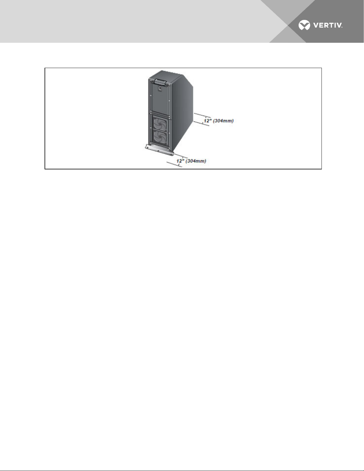
Figure 5.1 Clearances
Vertiv | Liebert® Maintenance Bypass Cabinet Installer/User Guide | 16
Page 17
6 UNLOADING
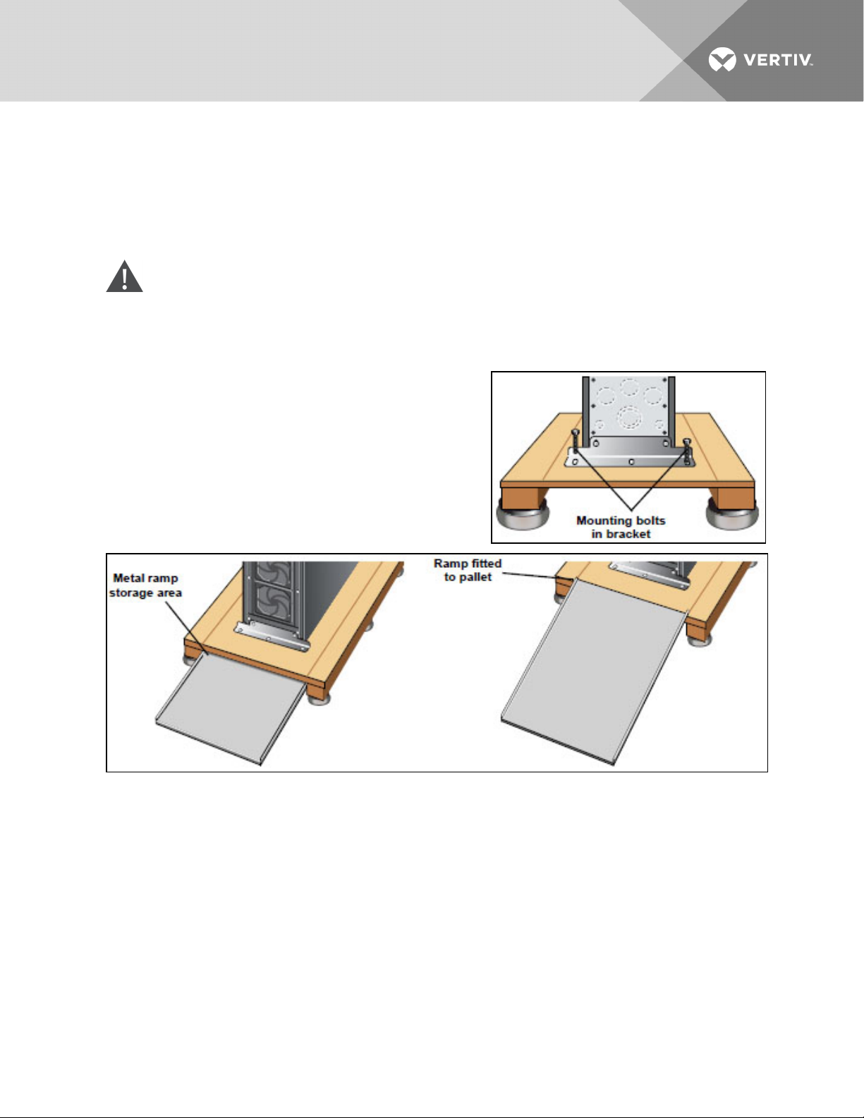
The unit frame is bolted to the shipping pallet to ensure safety. We recommend using a pallet jack to
transport the unit to its operating location prior to unbolting the unit.
6.1 Unloading the Maintenance Bypass Cabinet
CAUTION: This Maintenance Bypass Cabinet is heavy (see weight in Table 5.1 on page15). At
least two people should assist to unload it from the pallet.
1. Once the Maintenance Bypass Cabinet is near the desired operating location, remove the
cardboard cover.
2. Use a 1/2" (13mm) wrench to remove the eight
mounting bolts (four per bracket) from the pallet
brackets. Remove mounting brackets from the
pallet and Maintenance Bypass Cabinet. Keep
brackets and bolts for future transportation of the
cabinet or for securing the cabinet to the floor.
3. Remove the metal ramp from the bottom of the
pallet, rotating it 180°. Fit ramp onto opposite side
of pallet (in slot) as shown below.
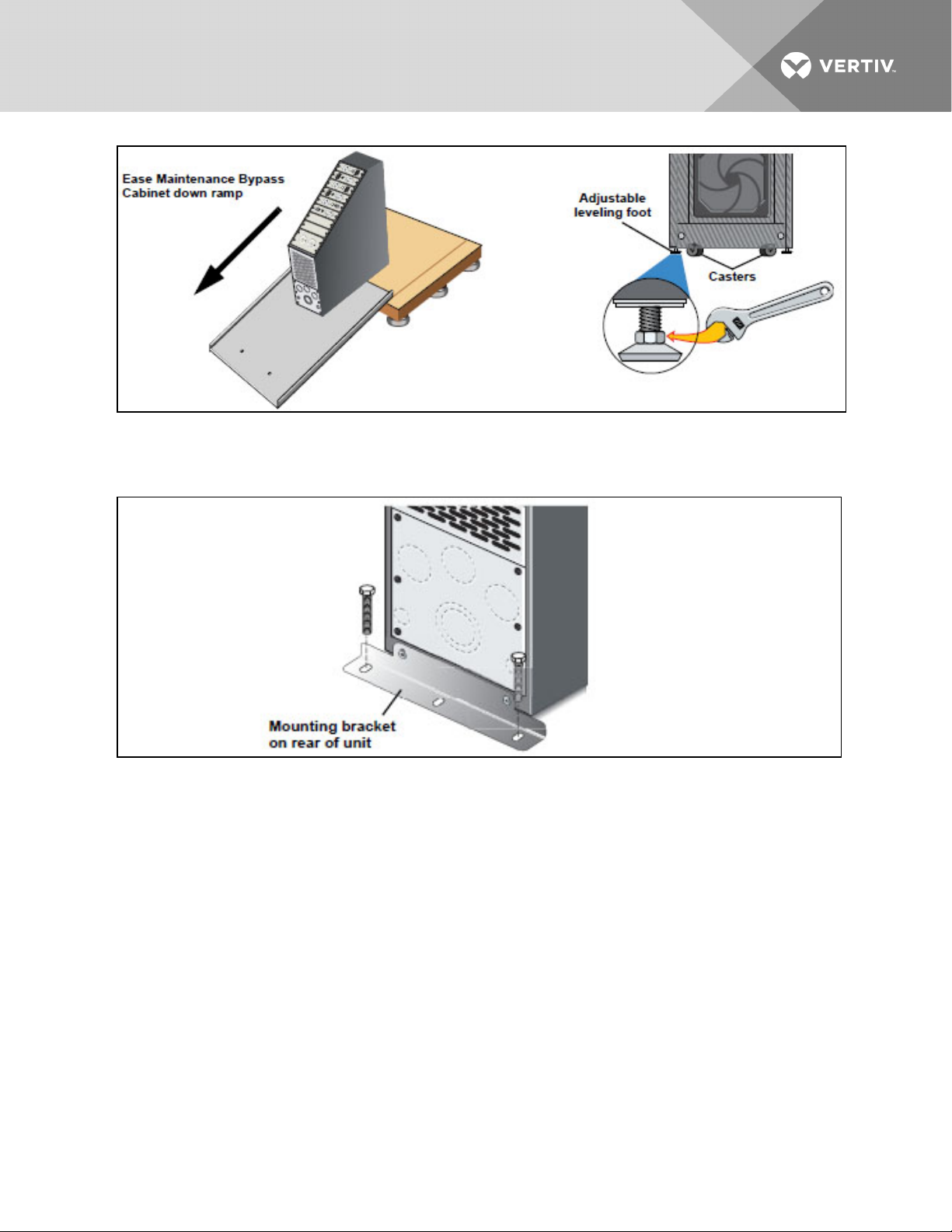
4. Using two people, slowly roll the cabinet down the ramp until the unit is on a level surface (see
below, left).
5. Once the cabinet is in the desired location, adjust the leveling feet to secure its position (see
below, right).
Vertiv | Liebert® Maintenance Bypass Cabinet Installer/User Guide | 17
Page 18
6.2 Stationary Mounting
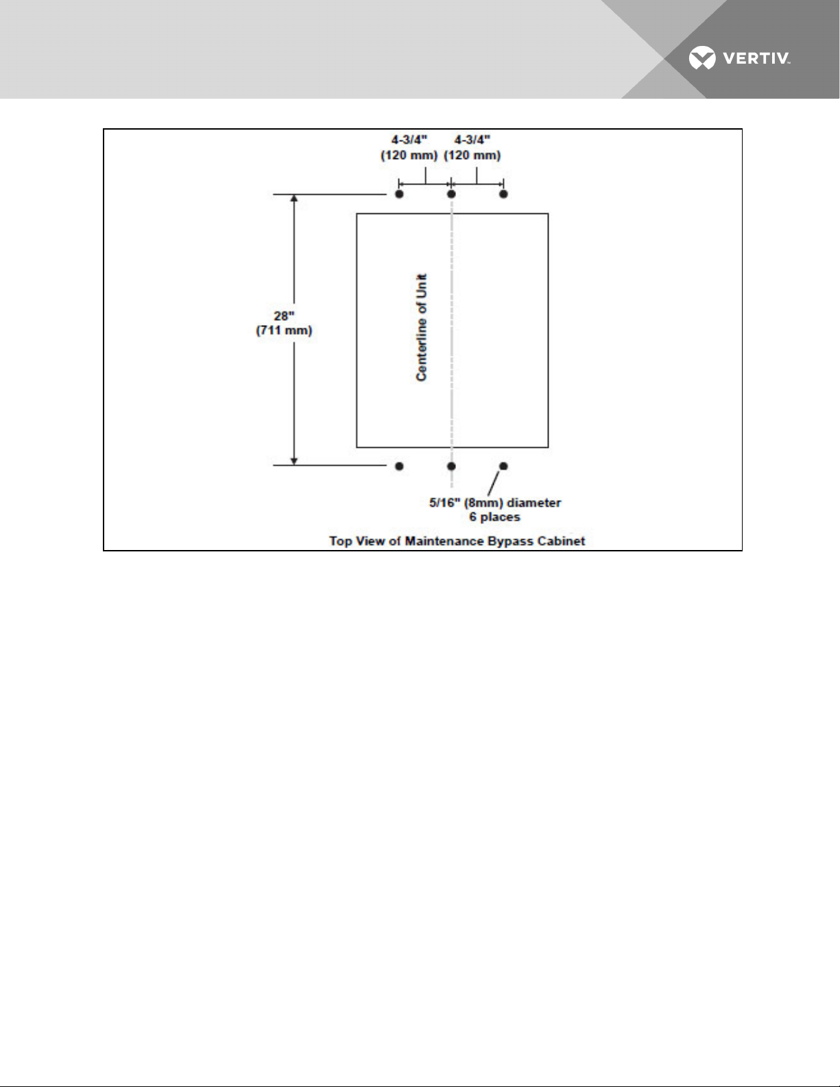
Additional stability can be added by bolting the mounting brackets (used in shipping) to the floor.
For greater stability, use a higher-grade bolt. Refer to the dimensions below when drilling holes for
stationary mounting.
Vertiv | Liebert® Maintenance Bypass Cabinet Installer/User Guide | 18
Page 19
Vertiv | Liebert® Maintenance Bypass Cabinet Installer/User Guide | 19
Page 20

This page intentionally left blank.
Vertiv | Liebert® Maintenance Bypass Cabinet Installer/User Guide | 20
Page 21

7 CABLE INSTALLATION
7.1 Wiring Preparation
WARNING! Please read this section thoroughly before attempting to install wiring to this unit.
Be sure that the unit is not connected to any AC mains power source or UPS before installing any wiring
to this unit. This Maintenance Bypass Cabinet should be installed by a qualified / certified electrician.
7.2 Preparing Internal Wiring
The Maintenance Bypass Cabinet is factory-configured for single-source installations. If your installation
requires dual-source capabilities, the cabinet’s wiring must be modified.
7.3 Dual Source Configuration
Modifying the wiring consists of removing the jumpers between TB1 and TB2 as described below:
1. Remove cover plates.
2. Identify TB1 and TB2.
3. Using a 3/16" Allen wrench, loosen terminal mounting jumpers between TB1 and TB2.
4. Remove jumpers and retighten terminals to 50 in-lb.
5. Connect primary source to TB2 and secondary source to TB1.
Vertiv | Liebert® Maintenance Bypass Cabinet Installer/User Guide | 21
Page 22
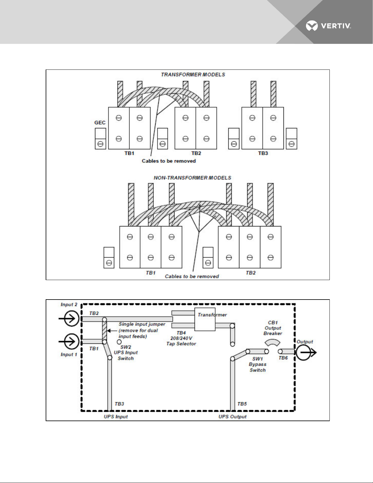
Figure 7.1 Jumper removal—transformer models and non-transformer models
Figure 7.2 Maintenance Bypass Cabinet with transformer
Vertiv | Liebert® Maintenance Bypass Cabinet Installer/User Guide | 22
Page 23
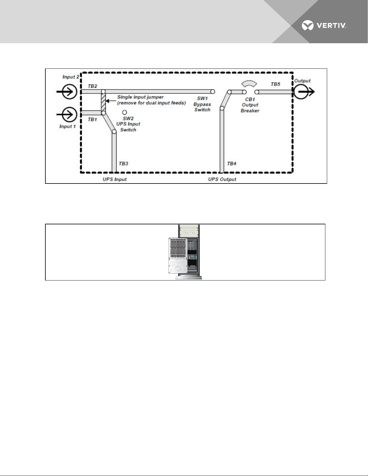
Figure 7.3 Maintenance Bypass Cabinet without transformer
7.4 Removing the Cover Plates
On the back of the Maintenance Bypass Cabinet, cover plates are over the input and output terminals
(see illustration below). Remove these using a phillips screwdriver. Keep screws and plates to one side.
7.5 REPO Connection
Refer to the Installer/User Guide for you Liebert UPS unit for information on connecting the REPO.
7.6 Input and Output Wiring
NOTE: Input wiring must be installed using conduit. 208 input voltage jumper—if only the connections
for 208VAC are made between the UPS and the Maintenance Bypass, the 208 input voltage jumper
must be installed for proper operation. To install this jumper, place the jumper wire provided in the
accessory kit between Pin1 and Pin2 on TB4.
Vertiv | Liebert® Maintenance Bypass Cabinet Installer/User Guide | 23
Page 24
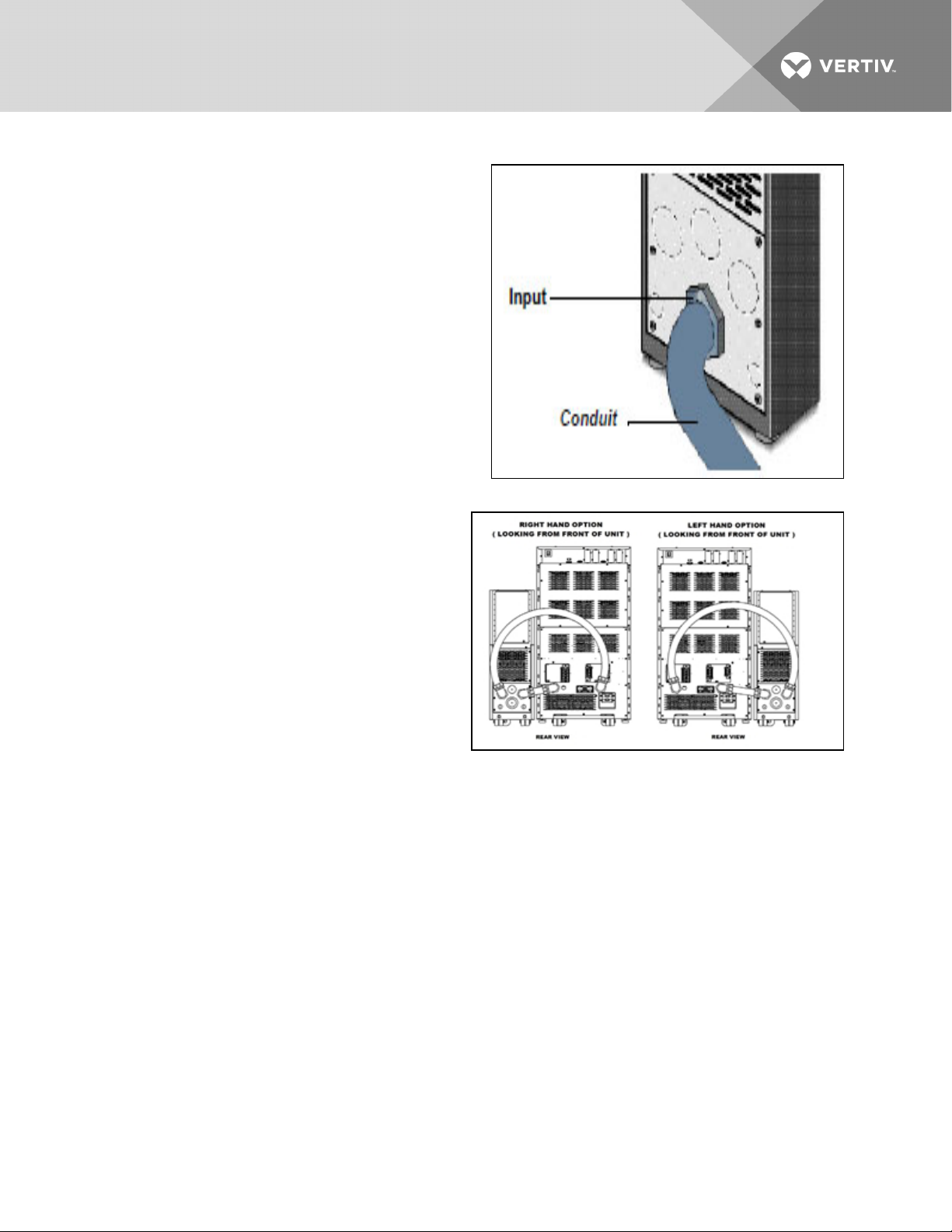
To connect the input wiring:
1. Locate the input wiring access (see
illustration at right).
2. Remove the knockout and pull the
three/four input wires through it, allowing
some slack for installation.
3. Secure the conduit to the rear panel of the
Maintenance Bypass Cabinet.
4. Input power cables connect to hex
terminals on the input terminal block.
5. Insert the ground (earth) wire through the
earth lug and tighten it to the proper
torque value (120in-lb). Then connect the
wires to the block connections as shown at
right. Using a torque wrench, turn the
screws clockwise until tightened to the
proper torque value (50in-lb).
NOTE: The Liebert UPS and Maintenance Bypass
Cabinet with transformer contain an isolation
transformer that generates a neutral conductor
for the connected equipment. The UPS and
Maintenance Bypass with transformer are a
separately derived source and contain a
neutral-to-ground bonding jumper. A grounding
electrode conductor (GEC) must be installed in
accordance with national and local wiring codes
and regulations.
Vertiv | Liebert® Maintenance Bypass Cabinet Installer/User Guide | 24
Page 25
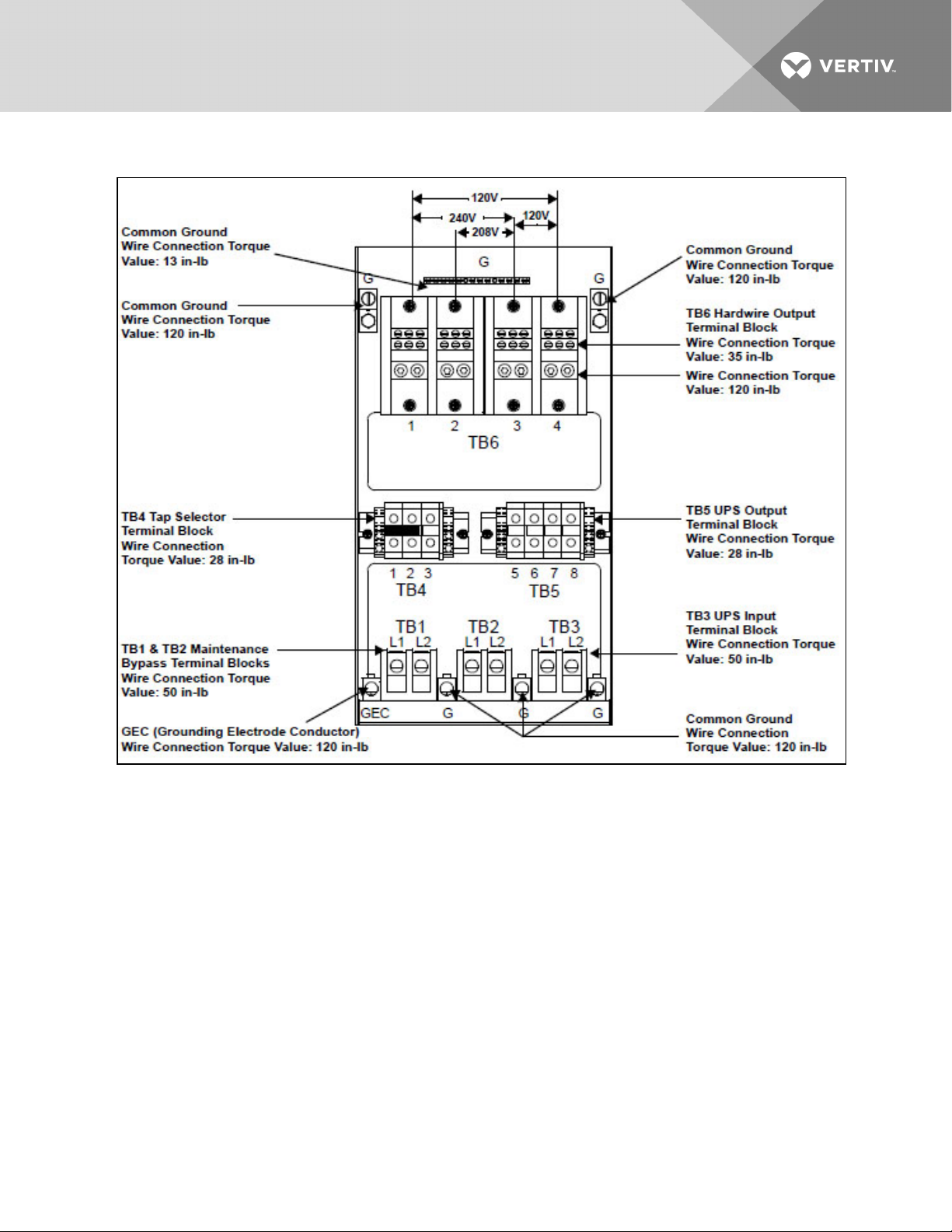
Figure 7.4 Electrical connections—transformer model MBC
Vertiv | Liebert® Maintenance Bypass Cabinet Installer/User Guide | 25
Page 26
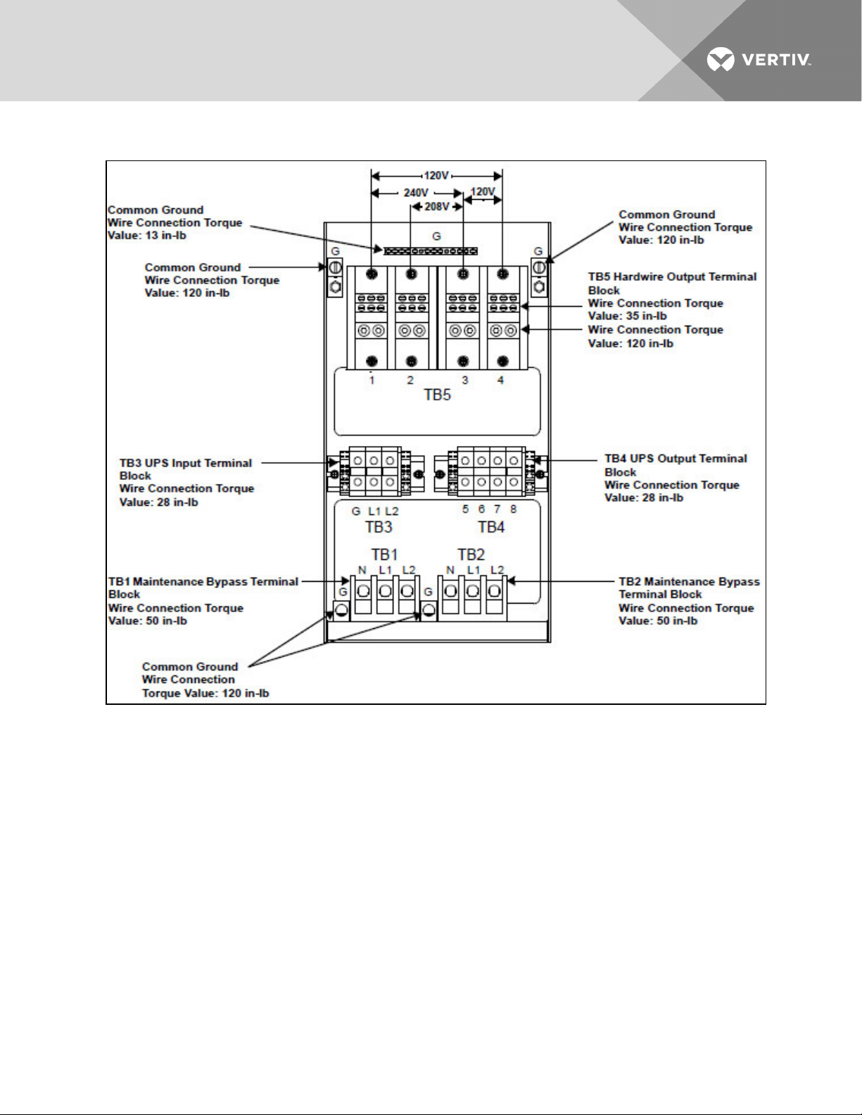
Figure 7.5 Electrical connections—non-transformer model MBC
Vertiv | Liebert® Maintenance Bypass Cabinet Installer/User Guide | 26
Page 27
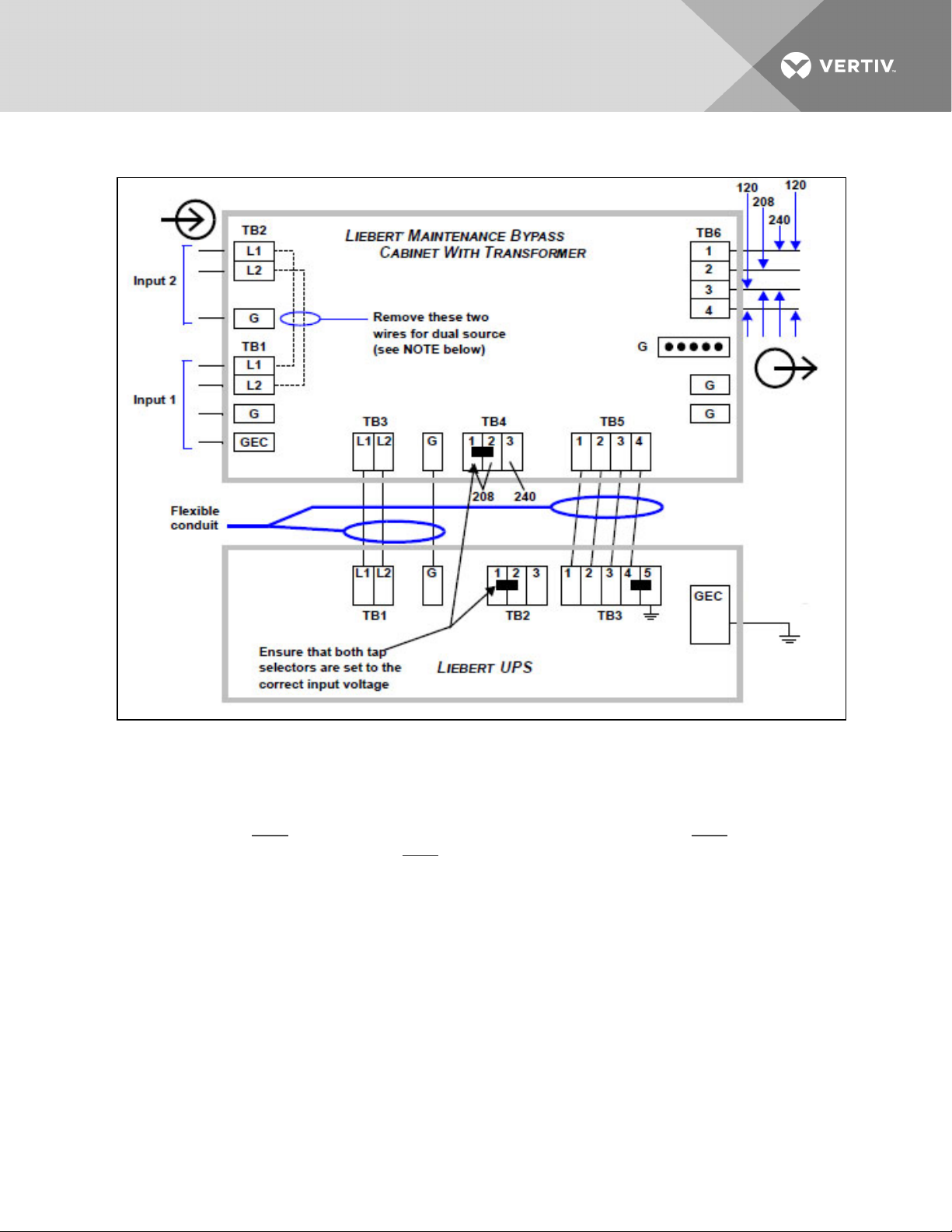
Figure 7.6 Connecting Liebert UPS to Maintenance Bypass Cabinet with transformer
NOTE:
1. SINGLE-SOURCE FEED—If feeding the Maintenance Bypass Cabinet from a single source, the input
connection may be made to either TB1 or TB2.
2. DUAL-SOURCE FEED—If feeding the Maintenance Bypass Cabinet from a dual source, the UPS input
supply connection must be made to TB1 and the bypass input supply connection must be made to
TB2. The jumpers between TB1 and TB2 must be removed.
3. If connected equipment is a combination of 208 VAC and 120 VAC, use a three-phase panel board
connected to the output terminal TB6.
Vertiv | Liebert® Maintenance Bypass Cabinet Installer/User Guide | 27
Page 28
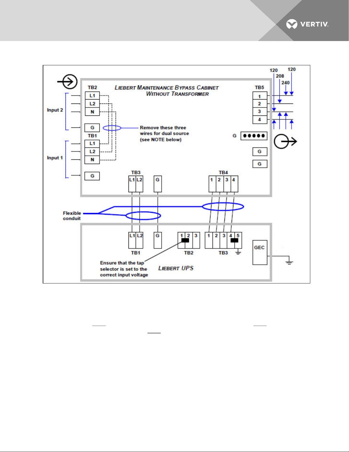
Figure 7.7 Connecting Liebert UPS to a Maintenance Bypass Cabinet without transformer
NOTE:
1. SINGLE-SOURCE FEED—If feeding the Maintenance Bypass Cabinet from a single source, the input
connection may be made to either TB1 or TB2.
2. DUAL-SOURCE FEED—If feeding the Maintenance Bypass Cabinet from a dual source, the UPS input
supply connection must be made to TB1 and the bypass input supply connection must be made to
TB2. The jumpers between TB1 and TB2 must be removed.
3. If connected equipment is a combination of 208 VAC and 120 VAC, use a three-phase panel board
connected to the output terminal TB5.
Vertiv | Liebert® Maintenance Bypass Cabinet Installer/User Guide | 28
Page 29

8 OPERATION
8.1 Start-Up and Initialization
To start up the UPS while it is connected to the Maintenance Bypass:
1. Set the Maintenance Bypass switch (SW1) to the UPS position on the Maintenance Bypass
Cabinet.
2. Close the UPS Source Switch (SW2).
3. Close the output circuit breaker (CB1).
4. Close the UPS input circuit breaker (CB1).
5. On Liebert GXT2 & Liebert GXT3 UPS models:
• Close the UPS output circuit breaker.
• Press the ON/OFF button.
On Liebert GXT4 UPS models:
• Close the UPS output circuit breaker.
• Press the UP or DOWN button, then press Enter to confirm action.
On Liebert Nfinity UPS models:
• Close the control enable switch.
• After the UPS has initialized, turn the UPS output on by pushing the standby button.
• Close the UPS output circuit breaker.
On Liebert APS UPS models:
• Close the control enable switch.
• After the UPS has initialized, turn the UPS output on by pushing the ON/OFF button then
press the Enter (F5) button to confirm action when prompted on the LCD display.
• Close the UPS output circuit breaker.
8.2 Shutting Down the UPS
To power down the entire system including connected equipment:
1. On Liebert GXT2 & Liebert GXT3 UPS models:
• Open the UPS output circuit breaker.
• Press the ON/OFF button twice in 3 seconds.
On Liebert GXT4 UPS models:
• Open the UPS output circuit breaker.
• Navigate to the Control menu and select Turn OFF UPS and then press Enter to confirm
action.
On Liebert Nfinity UPS models:
• Open the UPS output circuit breaker.
• Turn the UPS output off through the User Interface display.
• Open the control enable switch.
Vertiv | Liebert® Maintenance Bypass Cabinet Installer/User Guide | 29
Page 30

On Liebert APS UPS models:
• Open the UPS output circuit breaker.
• Open the control enable switch.
2. Open the UPS input circuit breaker.
3. Open the UPS Source Switch (SW2) on the Maintenance Bypass Cabinet.
4. Open the output circuit breaker (CB1) on the Maintenance Bypass Cabinet.
8.3 Transferring the System fromUPStoMaintenanceBypassOperation
1. Verify that the amber Bypass lamp is illuminated (located near the rotary-bypass switch on the
Maintenance Bypass Cabinet).
2. Turn the Bypass Switch (SW1) to the bypass position on the Maintenance Bypass Cabinet.
The connected equipment is now powered from the bypass source and is not protected by the
UPS.
3. If you are servicing or replacing the UPS, follow steps 1, 2, and 3 in Shutting Down the UPS on
the previous page to shut down the UPS.
NOTE: Do not perform Step 4 because this will remove power from the connected equipment.
8.4 Transferring the System fromMaintenanceBypasstoUPSOperation
If the UPS was shut down for service or was replaced:
1. Close the UPS Source Switch (SW2) on the Maintenance Bypass Cabinet.
2. Close the UPS input circuit breaker.
3. On Liebert GXT2 & Liebert GXT3 UPS models:
• Close the UPS output circuit breaker.
• Press the ON/OFF button.
On Liebert GXT4 UPS models:
• Close the UPS output circuit breaker.
• Press the UP or DOWN button, then press Enter to confirm action.
On Liebert Nfinity UPS models:
• Close the control enable switch.
• After the UPS has initialized, turn the UPS output on by pushing the standby button.
• Close the UPS output circuit breaker.
On Liebert APS UPS models:
• Close the control enable switch.
• After the UPS has initialized, turn the UPS output on by pushing the ON/OFF button then
press the Enter (F5) button to confirm action when prompted on the LCD display.
• Close the UPS output circuit breaker.
4. Verify that the green UPS lamp is illuminated (located near the rotary-bypass switch on the
Maintenance Bypass Cabinet.
5. Turn the Bypass switch (SW1) to the UPS position on the Maintenance Bypass Cabinet.
The connected equipment is now powered and is protected by the UPS.
Vertiv | Liebert® Maintenance Bypass Cabinet Installer/User Guide | 30
Page 31
9 MAINTENANCE
9.1 Proper Care
Keeping your Liebert Maintenance Bypass Cabinet operating properly is imperative to optimal
performance and life of the unit. It is recommended that a certified technician perform preventive and
corrective maintenance. Vertiv™ Services is dedicated to ensuring the highest level of performance and
unmatched support for your Maintenance Bypass Cabinet . Contact a Vertiv™ representative for services
to guarantee maximum reliability and system availability.
9.2 Scheduled Maintenance
We recommend performing the following maintenance at least monthly:
• Check, clean and replace filters.
• Verify that airflow is not obstructed.
We recommend performing the following maintenance annually:
• Verify all power connections.
• Verify that all output distribution modules are operating properly.
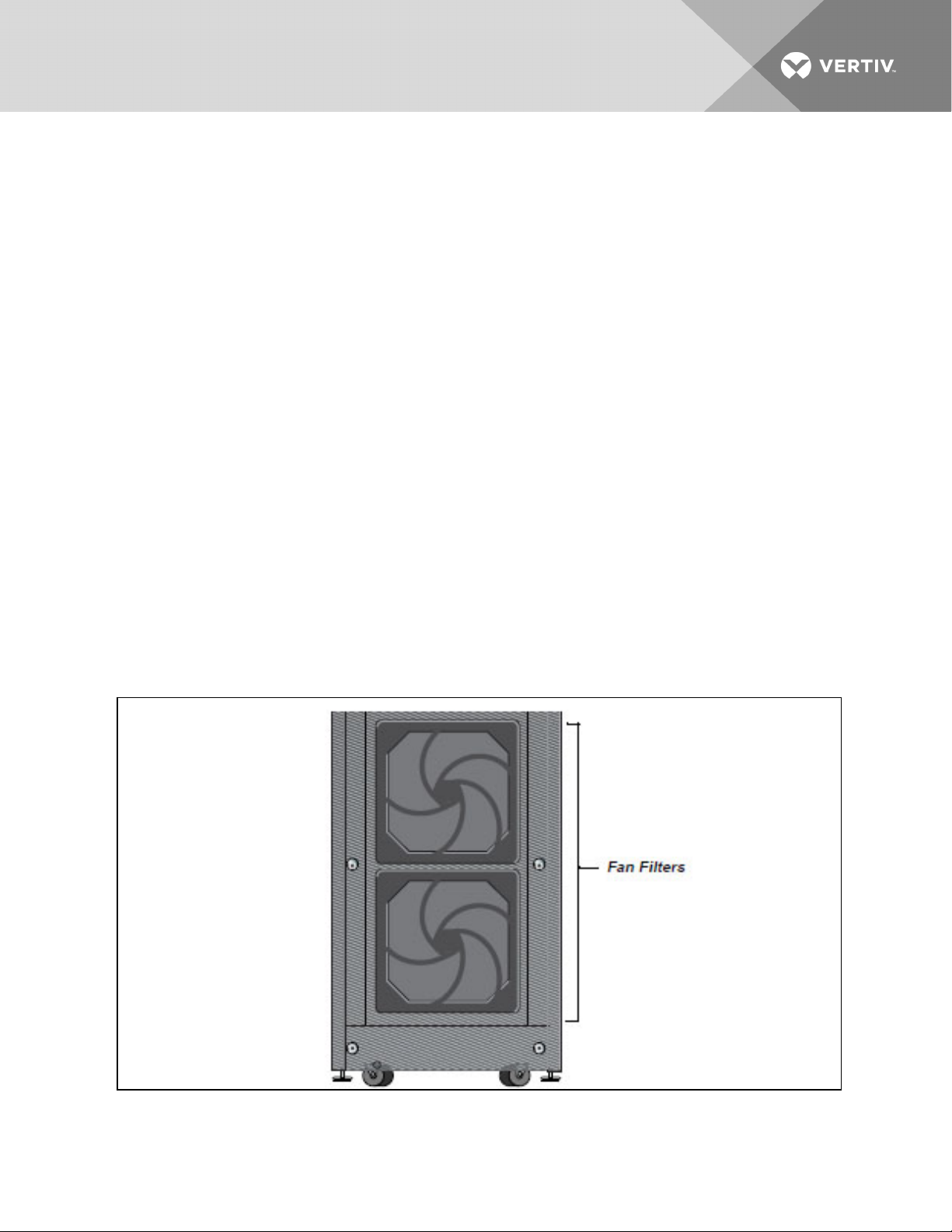
9.2.1 Replacing Fan Filters—Transformer Models Only
The Maintenance Bypass Cabinet intake fans contain filters that will need to be replaced or cleaned
periodically, depending on the surrounding environment. Check by noting the condition of the two filters.
If filters are dirty, replace or wash them. The filters may be taken out of the UPS for replacement or
cleaning by removing the plastic cover over the filter frame. Use caution when replacing filters when fans
are running.
Vertiv | Liebert® Maintenance Bypass Cabinet Installer/User Guide | 31
Page 32

The fan filters are washable and may be reused. To wash these filters, place them under a running faucet
(with the dirty side down) to remove dirt and dust. Blot dry with a towel and allow to air-dry before
reusingit.
Vertiv | Liebert® Maintenance Bypass Cabinet Installer/User Guide | 32
Page 33
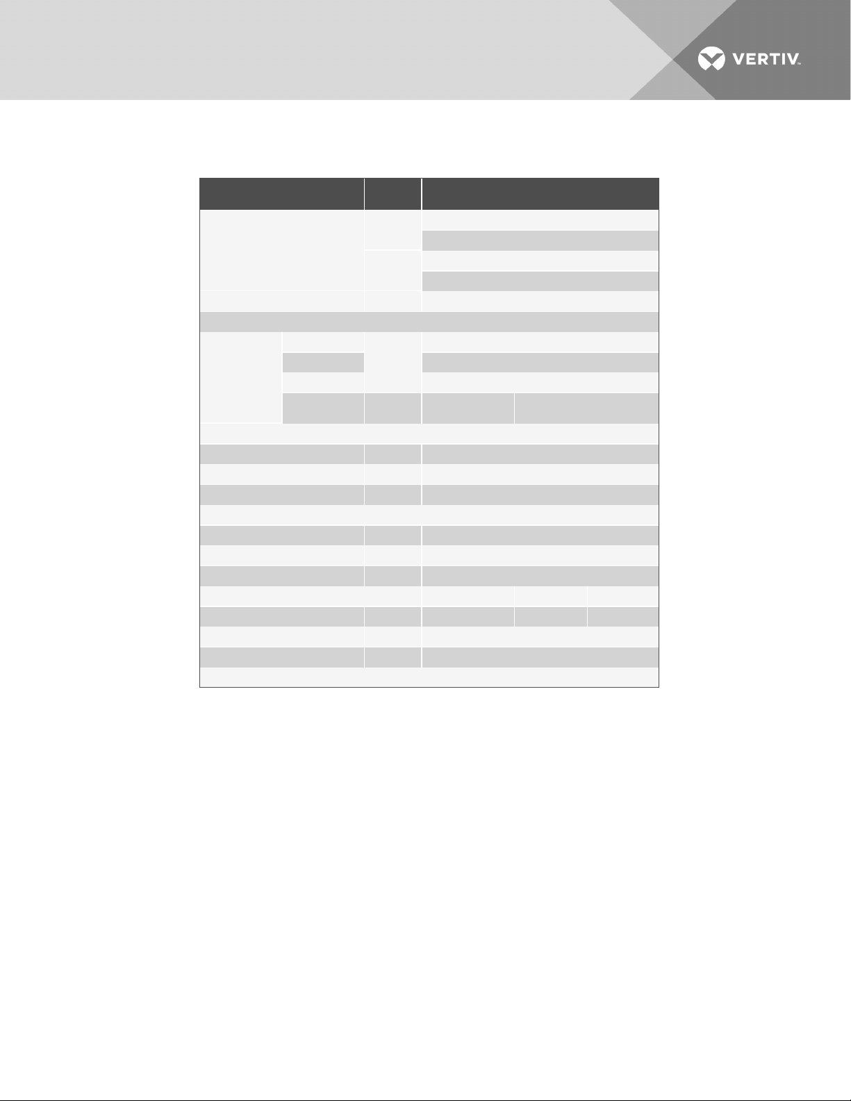
10 SPECIFICATIONS
GENERAL & ENVI RONMENTAL RATING
kVA
Unit Rating
Amps
Safety Standards UL 1778, c-UL
Mechanical
Width
Depth 26.5 (700)
Dimensions
Environmental
OperatingTemperature (max) F ( C) 32º - 104º (0º - 40º)
Relative Humidity % 0-95% non-condensing
Maximum OperatingAltitude Ft (M) 10,000 (3000)
InputData
Nominal Input Voltage VAC 208 or 240
InputFrequency (nominal) Hz 60
InputFrequency Range Hz 55-65
Output Data 208/240 240 208
Output Voltage VAC 120/120/208/240 120/120/24 0* 120/120/208*
Transfer Time msec <4 msec typical
Output Frequency Hz 60
* Transformerless model requires neutral input
Height 30.4 (775)
Weight lb (kg)
In (mm)
Models NMB1x and NMB4x = 18
Models NMB5x andNMB8x =20
Models NMB1x and NMB4x = 100 max
Models NMB5x andNMB8x =125 max
9.5 (241)
287 (130)
transformer model
85 (39)
transformerless model
Vertiv | Liebert® Maintenance Bypass Cabinet Installer/User Guide | 33
Page 34

This page intentionally left blank.
Vertiv | Liebert® Maintenance Bypass Cabinet Installer/User Guide | 34
Page 35

Page 36

VertivCo.com | Vertiv Headquarters, 1050 Dearborn Drive, Columbus, OH, 43085, USA
© 2017 Vertiv Co. Allrights reserved. Vertiv and the Vertiv logo are trademarks or registered trademarks of Vertiv Co. Allother names andlogos referred to
are trade names, trademarks or registered trademarks of their respective owners. While every precaution has been taken to ensure accuracy and
completeness herein, Vertiv Co. assumes no responsibility, and disclaimsallliability, for damages resulting from use of this information or for any errors or
omissions. Specifications are subject to change without notice.
SL-23960_REV8_11-17/590-1332-501B
 Loading...