

Page 1

Liebert®
LDMF™ Distribution Monitoring
User Manual
Page 2

The information contained in this document is subject to change
without notice and may not be suitable for all applications. While
every precaution has been taken to ensure the accuracy and
completeness of this document, Vertiv assumes no responsibility
and disclaims all liability for damages resulting from use of this
information or for any errors or omissions. Refer to other local
practices or building codes as applicable for the correct methods,
tools, and materials to be used in performing procedures not
specifically described in this document.
The products covered by this instruction manual are manufactured
and/or sold by Vertiv This document is the property of Vertiv and
contains confidential and proprietary information owned by Vertiv.
Any copying, use or disclosure of it without the written permission of
Vertiv is strictly prohibited.
Names of companies and products are trademarks or registered
trademarks of the respective companies. Any questions regarding
usage of trademark names should be directed to the original
manufacturer.
Technical Support Site
If you encounter any installation or operational issues with your product, check the pertinent
section of this manual to see if the issue can be resolved by following outlined procedures.
Visit https://www.VertivCo.com/en-us/support/ for additional assistance.
Page 3

TABLE OF CONTENTS
IMPORTANT SAFETY INSTRUCTIONS . . . . . . . . . . . . . . . . . . . . . . . . . . . . . . . . . . . . . . 1
1.0 GLOSSARY OF ABBREVIATIONS . . . . . . . . . . . . . . . . . . . . . . . . . . . . . . . . . . . . . . 2
2.0 PRODUCT OVERVIEW . . . . . . . . . . . . . . . . . . . . . . . . . . . . . . . . . . . . . . . . . . . . . . . . . 3
3.0 MAJOR COMPONENTS. . . . . . . . . . . . . . . . . . . . . . . . . . . . . . . . . . . . . . . . . . . . . . . . 4
3.1 PM4 Monitor Board (PMB). . . . . . . . . . . . . . . . . . . . . . . . . . . . . . . . . . . . . . . . . . . . . . . . . . . . . . . . . . . . . . . 4
3.2 PM4 Interface Board (PIB) . . . . . . . . . . . . . . . . . . . . . . . . . . . . . . . . . . . . . . . . . . . . . . . . . . . . . . . . . . . . . . .4
3.3 PM4 Large Interface Board (PLIB). . . . . . . . . . . . . . . . . . . . . . . . . . . . . . . . . . . . . . . . . . . . . . . . . . . . . . . 5
3.4 Branch Circuit Monitoring Sensor Module (BSM). . . . . . . . . . . . . . . . . . . . . . . . . . . . . . . . . . . . . . . . 6
3.5 Power Supply With EMI Filter . . . . . . . . . . . . . . . . . . . . . . . . . . . . . . . . . . . . . . . . . . . . . . . . . . . . . . . . . . . . 6
3.6 Human-Machine Interface/Display Assembly (Optional). . . . . . . . . . . . . . . . . . . . . . . . . . . . . . . . 7
3.7 PM4 Adapter Board. . . . . . . . . . . . . . . . . . . . . . . . . . . . . . . . . . . . . . . . . . . . . . . . . . . . . . . . . . . . . . . . . . . . . . 8
4.0 INSTALLATION. . . . . . . . . . . . . . . . . . . . . . . . . . . . . . . . . . . . . . . . . . . . . . . . . . . . . . . .9
4.1 Installing a BSM (CT Module Assembly) . . . . . . . . . . . . . . . . . . . . . . . . . . . . . . . . . . . . . . . . . . . . . . . . . 9
4.1.1 Connecting Panelboards A and B . . . . . . . . . . . . . . . . . . . . . . . . . . . . . . . . . . . . . . . . . . . . . . . . . . . . . . . . 9
4.2 Installing a Solid-Core Current Transformer . . . . . . . . . . . . . . . . . . . . . . . . . . . . . . . . . . . . . . . . . . . . 10
4.3 Installing a Current Transformer on the PIB Interface Board. . . . . . . . . . . . . . . . . . . . . . . . . . . . 11
4.4 Connecting a Current Transformer to the PM4 Large Interface Board (PLIB) . . . . . . . . . . 14
5.0 OPERATION . . . . . . . . . . . . . . . . . . . . . . . . . . . . . . . . . . . . . . . . . . . . . . . . . . . . . . . . . . 17
5.1 Alarms . . . . . . . . . . . . . . . . . . . . . . . . . . . . . . . . . . . . . . . . . . . . . . . . . . . . . . . . . . . . . . . . . . . . . . . . . . . . . . . . . . 18
5.2 Communication . . . . . . . . . . . . . . . . . . . . . . . . . . . . . . . . . . . . . . . . . . . . . . . . . . . . . . . . . . . . . . . . . . . . . . . . . 19
5.2.1 LDMF Setup Port Connection . . . . . . . . . . . . . . . . . . . . . . . . . . . . . . . . . . . . . . . . . . . . . . . . . . . . . . . . . . . 19
5.2.2 Modbus Connection . . . . . . . . . . . . . . . . . . . . . . . . . . . . . . . . . . . . . . . . . . . . . . . . . . . . . . . . . . . . . . . . . . . . . 19
5.3 Downloading the Software. . . . . . . . . . . . . . . . . . . . . . . . . . . . . . . . . . . . . . . . . . . . . . . . . . . . . . . . . . . . . .20
5.4 Using the Monitor Tool (Used Only for Startup and Diagnostics). . . . . . . . . . . . . . . . . . . . . . .20
5.4.1 Starting the Monitor Tool. . . . . . . . . . . . . . . . . . . . . . . . . . . . . . . . . . . . . . . . . . . . . . . . . . . . . . . . . . . . . . . .20
5.4.2 Monitor Menu Options . . . . . . . . . . . . . . . . . . . . . . . . . . . . . . . . . . . . . . . . . . . . . . . . . . . . . . . . . . . . . . . . . . 21
5.4.3 Panel Status and Real-Time Clock. . . . . . . . . . . . . . . . . . . . . . . . . . . . . . . . . . . . . . . . . . . . . . . . . . . . . . . 22
5.4.4 Main Breaker Status . . . . . . . . . . . . . . . . . . . . . . . . . . . . . . . . . . . . . . . . . . . . . . . . . . . . . . . . . . . . . . . . . . . . . 22
5.4.5 Breaker Status. . . . . . . . . . . . . . . . . . . . . . . . . . . . . . . . . . . . . . . . . . . . . . . . . . . . . . . . . . . . . . . . . . . . . . . . . . . 22
5.4.6 Mode Buttons . . . . . . . . . . . . . . . . . . . . . . . . . . . . . . . . . . . . . . . . . . . . . . . . . . . . . . . . . . . . . . . . . . . . . . . . . . . 23
Vertiv | Liebert® LDMF™ Distribution Monitoring User Manual | i
Page 4

5.5 Using the Configuration Tool . . . . . . . . . . . . . . . . . . . . . . . . . . . . . . . . . . . . . . . . . . . . . . . . . . . . . . . . . . .23
5.5.1 Starting the Configuration Program. . . . . . . . . . . . . . . . . . . . . . . . . . . . . . . . . . . . . . . . . . . . . . . . . . . . .24
5.5.2 Main Configuration Window Overview . . . . . . . . . . . . . . . . . . . . . . . . . . . . . . . . . . . . . . . . . . . . . . . . . . 25
5.5.3 Load a Configuration File from Disk . . . . . . . . . . . . . . . . . . . . . . . . . . . . . . . . . . . . . . . . . . . . . . . . . . . . .26
5.5.4 Install Configuration Changes in the Unit . . . . . . . . . . . . . . . . . . . . . . . . . . . . . . . . . . . . . . . . . . . . . . . 26
5.5.5 Save the Configuration File to Disk. . . . . . . . . . . . . . . . . . . . . . . . . . . . . . . . . . . . . . . . . . . . . . . . . . . . . . 27
5.5.6 Select Panel to View. . . . . . . . . . . . . . . . . . . . . . . . . . . . . . . . . . . . . . . . . . . . . . . . . . . . . . . . . . . . . . . . . . . . . 27
5.5.7 Select Breakers to View . . . . . . . . . . . . . . . . . . . . . . . . . . . . . . . . . . . . . . . . . . . . . . . . . . . . . . . . . . . . . . . . . 27
5.5.8 Edit the Liebert LDMF Unit Properties . . . . . . . . . . . . . . . . . . . . . . . . . . . . . . . . . . . . . . . . . . . . . . . . . . 28
5.5.9 Edit the Panel Properties or Set a Password. . . . . . . . . . . . . . . . . . . . . . . . . . . . . . . . . . . . . . . . . . . . .28
5.5.10 Edit the Breaker Properties. . . . . . . . . . . . . . . . . . . . . . . . . . . . . . . . . . . . . . . . . . . . . . . . . . . . . . . . . . . . . . 29
5.5.11 Add a Circuit Breaker. . . . . . . . . . . . . . . . . . . . . . . . . . . . . . . . . . . . . . . . . . . . . . . . . . . . . . . . . . . . . . . . . . . .30
5.5.12 Adding a Subfeed Breaker. . . . . . . . . . . . . . . . . . . . . . . . . . . . . . . . . . . . . . . . . . . . . . . . . . . . . . . . . . . . . . . 31
5.5.13 Delete a Circuit Breaker/Subfeed Breaker. . . . . . . . . . . . . . . . . . . . . . . . . . . . . . . . . . . . . . . . . . . . . . . 32
5.6 Upgrading the Firmware . . . . . . . . . . . . . . . . . . . . . . . . . . . . . . . . . . . . . . . . . . . . . . . . . . . . . . . . . . . . . . . .33
5.7 Display Controls (HMI) . . . . . . . . . . . . . . . . . . . . . . . . . . . . . . . . . . . . . . . . . . . . . . . . . . . . . . . . . . . . . . . . .36
5.7.1 Controls and Indicators. . . . . . . . . . . . . . . . . . . . . . . . . . . . . . . . . . . . . . . . . . . . . . . . . . . . . . . . . . . . . . . . . . 37
5.7.2 Liebert LDMF Parameter Screens . . . . . . . . . . . . . . . . . . . . . . . . . . . . . . . . . . . . . . . . . . . . . . . . . . . . . . .38
5.7.3 Liebert LDMF Alarms. . . . . . . . . . . . . . . . . . . . . . . . . . . . . . . . . . . . . . . . . . . . . . . . . . . . . . . . . . . . . . . . . . . .38
5.7.4 Liebert LDMF Screens. . . . . . . . . . . . . . . . . . . . . . . . . . . . . . . . . . . . . . . . . . . . . . . . . . . . . . . . . . . . . . . . . . .39
6.0 SPECIFICATIONS. . . . . . . . . . . . . . . . . . . . . . . . . . . . . . . . . . . . . . . . . . . . . . . . . . . . 42
7.0 TROUBLESHOOTING / FREQUENTLY ASKED QUESTIONS . . . . . . . . . . . 43
FIGURES
Figure 1 RS-232 port . . . . . . . . . . . . . . . . . . . . . . . . . . . . . . . . . . . . . . . . . . . . . . . . . . . . . . . . . . . . . . . . . . . . . . . . . 19
Figure 2 Main panelboard screens—examples . . . . . . . . . . . . . . . . . . . . . . . . . . . . . . . . . . . . . . . . . . . . . . .39
Figure 3 Subfeed screens—examples . . . . . . . . . . . . . . . . . . . . . . . . . . . . . . . . . . . . . . . . . . . . . . . . . . . . . . . 40
Figure 4 Branch breaker screens—examples. . . . . . . . . . . . . . . . . . . . . . . . . . . . . . . . . . . . . . . . . . . . . . . . . 41
TAB LES
Table 1 CT matrix for the Liebert LDMF . . . . . . . . . . . . . . . . . . . . . . . . . . . . . . . . . . . . . . . . . . . . . . . . . . . . . . 5
Table 2 Large branch breaker CT wiring. . . . . . . . . . . . . . . . . . . . . . . . . . . . . . . . . . . . . . . . . . . . . . . . . . . . . 11
Table 3 CT Table for Interface Board . . . . . . . . . . . . . . . . . . . . . . . . . . . . . . . . . . . . . . . . . . . . . . . . . . . . . . . . 12
Table 4 CT Table for PM4 Large Interface Board #1 . . . . . . . . . . . . . . . . . . . . . . . . . . . . . . . . . . . . . . . . . 15
Table 5 CT Table for PM4 Large Interface Board #2. . . . . . . . . . . . . . . . . . . . . . . . . . . . . . . . . . . . . . . . .16
Table 6 Parameters monitored for breakers . . . . . . . . . . . . . . . . . . . . . . . . . . . . . . . . . . . . . . . . . . . . . . . . . 17
Table 7 Alarm conditions and factory setpoints . . . . . . . . . . . . . . . . . . . . . . . . . . . . . . . . . . . . . . . . . . . . . 18
Table 8 Monitor Menu Options . . . . . . . . . . . . . . . . . . . . . . . . . . . . . . . . . . . . . . . . . . . . . . . . . . . . . . . . . . . . . . 21
Table 9 Monitor mode buttons . . . . . . . . . . . . . . . . . . . . . . . . . . . . . . . . . . . . . . . . . . . . . . . . . . . . . . . . . . . . . .23
Table 10 Overview of main Configuration window . . . . . . . . . . . . . . . . . . . . . . . . . . . . . . . . . . . . . . . . . . . .25
Table 11 Edit breaker properties and description. . . . . . . . . . . . . . . . . . . . . . . . . . . . . . . . . . . . . . . . . . . . .29
Vertiv | Liebert® LDMF™ Distribution Monitoring User Manual | ii
Page 5

IMPORTANT SAFETY INSTRUCTIONS
WARNING
As with all types of electrical equipment, dangerous voltages exist within the equipment
where the Liebert LDMF Distribution Monitor components are installed. For maximum
safety, ensure power is removed and circuit breakers/disconnects are tagged/locked out
per all applicable national, state and local electrical codes prior to working inside
equipment.
The area around the equipment must be free of any debris or standing water.
All power and control wiring must be installed by a qualified electrician in accordance with
the NEC and all applicable national, state and local codes.
ONLY qualified service personnel should perform maintenance and/or service on the
Liebert LDMF system. When performing maintenance and/or service on any component,
verify test equipment is insulated and has been inspected prior to use.
To avoid damage to the circuit boards, personnel handling these components should be
wearing an electrostatic discharge strap or other approved protective device.
When replacing or installing a solid core Current Transformer (CT), power must be
removed from equipment to prevent damage to the CT and/or circuit board. If the CT is a
split-core design, follow proper electrical safety procedures and ensure the CT wires are
connected to the applicable burdening circuit before attaching the CT around the
conductor.
These safety precautions are to be used in conjunction with NEC and local/state electrical
code.
ELECTROMAGNETIC COMPATIBILITY—The Liebert LDMF as a functional component of a
power distribution and supply product complies with the limits for a Class A Digital Device,
pursuant to Part 15 of FCC rules. Operation is subject to the following two conditions:
• This device must not cause harmful interference, and
• This device must accept any interference received, including interference that may cause undesired
operation.
Operating this device in a residential area is likely to cause harmful interference that users must
correct at their own expense.
Liebert LDMF as a functional component of a power distribution and supply product complies
with the requirements of EMC Directive 2004/108/EC and the published technical standards.
Continued compliance requires installation in accordance with these instructions and use of
accessories approved by Vertiv.
Vertiv™ | Liebert® LDMF™ Distribution Monitoring User Manual | 1
Page 6

1.0 GLOSSARY OF ABBREVIATIONS
The following abbreviations are used in this manual.
BCMS Branch Circuit Monitoring System
BMS Building Management System
BSM Branch Sensor Module
DSP Digital Signal Processor
GUI Graphic User Interface
HMI Human-Machine Interface
IGM Information Gathering Module
LDMF Liebert Distribution Monitor Front Access
LDMFS Liebert Distribution Monitor Front (Square-D Panelboards)
LDMFG Liebert Distribution Monitor Front (GE Panelboards)
LDMFI Liebert Distribution Monitor Front (I-Line Panelboards)
LDMF4
PAB PM4 Adapter Board
PCD Power Conditioning and Distribution
PDU Power Distribution Unit
PM4 Power Monitoring 4th Generation
Liebert Distribution Monitor Front (480V Distribution
Cabinets)
PIB PM4 Interface Board
PLIB PM4 Large Interface Board
PMB PM4 Monitoring Board
STP Service Terminal Port
Vertiv™ | Liebert® LDMF™ Distribution Monitoring User Manual | 2
Page 7

2.0 PRODUCT OVERVIEW
The Liebert LDMF monitors the main panelboard circuit breaker and individual panelboard
branch circuit breakers. The measurements are used to report the voltage, current and alarm
conditions for each breaker. The Liebert LDMF utilizes branch circuit sensor modules and
individual current transformers (CT) to monitor current. In addition, the Liebert LDMF monitors
options like subfeed and output circuit breakers and provides a full array of power parameters
and alarms.
The Liebert LDMF is available as an option for the Liebert PPC™, Liebert FDC™, Liebert FPC™,
Liebert RX™and Liebert RDC™.
The Liebert LDMF system can communicate with a Building Management System (BMS) and
Liebert SiteScan® Web via optional Liebert IntelliSlot™ cards or Liebert SiteLink® interface.
The Liebert LDMF consists of a monitor board, interface board, optional local display and Branch
Sensor Modules (BSM).
The Liebert LDMF is capable of receiving input from current branch sensor modules. The sensor
module (BSM) contains 100A current transformers (CTs) encapsulated in an epoxy-filled plastic
enclosure designed to be mounted next to the panelboard. Sensor modules are designed to work
3/4" or 1"-spaced panelboards. If a sensor module CT fails, connections are provided for up to six
replacement CTs. The optional CTs can be attached directly to the load cable feeding the failed
CT.
Higher-rated CTs may be used for monitoring optional subfeed circuit breakers. For subfeed
breakers, such as main panelboard breakers, the Liebert LDMF monitors not only the three-phase
current but also the ground and neutral current. These subfeed circuit breakers are in addition to
the panelboard circuit breakers that can be monitored through the BSM. The Liebert LDMF can
accommodate 18 individual large current transformers.
If your Liebert power center is supplied with a Square D® I-Line™ panelboard, the Liebert LDMF
can monitor it as well as its output breakers. A PM4 Large Interface Board (PLIB) replaces the
panelboard PM4 Interface Board (PIB) and can monitor up to 42 CTs. Each PLIB can monitor
eight four-wire or five-wire I-Line and/or subfeed breakers including ground and neutral current.
There are two (2) PLIBs per monitor board that can monitor up to 16 five-wire I-Line and/or
subfeed breakers.
The Liebert LDMF system includes three Liebert IntelliSlot ports for remote communication.
Optional Liebert IntelliSlot cards can provide the following remote communications:
• IS-WEBS card for SNMP/WEB with RJ-45 connection to Ethernet LAN
• IS-485S card for Modbus 485, 2-wire connection
• IS-IPBMS card for Modbus IP, with RJ-45 connection to Ethernet LAN
• IS-UNITY-DP card for HTTP/HTTPS, Vertiv Protocol, e-mail, SMS, SNMP v1/v2c/v3, BACnet IP/MSTP and
Modbus TCP/RTU output using a serial RS-485 two-wire connection
In addition to Liebert LDMF remote communications, an optional local display offers easy-to-use
viewing of electrical data for various branch breakers as well as alarm details such as the type and
source of each alarm.
Vertiv™ | Liebert® LDMF™ Distribution Monitoring User Manual | 3
Page 8
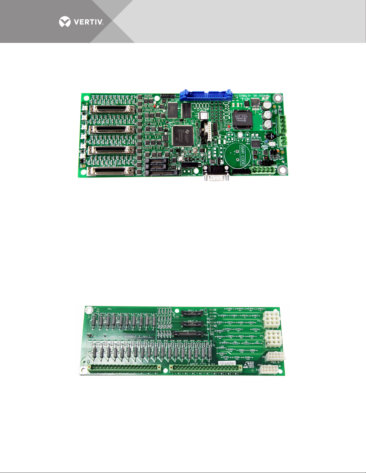
3.0 MAJOR COMPONENTS
3.1 PM4 Monitor Board (PMB)
The PM4 Monitor Board (PMB) is the main processing and storage circuit board. The PMB
contains the non-volatile memory where the configuration file is stored. The CT Module
Assemblies will connect directly to the PMB via the 4 ribbon cables connectors. The PMB is a
DSP-based logic controller with internal flash memory to store breaker configuration, alarms and
energy data. The on-board battery supplies power to the real-time clock.
All the electrical parameters are accumulated on the PMB for processing to Liebert Velocity
protocol for remote monitoring and the HMI interface for the local display. Kilowatt-hours (kWh)
data is accumulated on this board for the panelboard mains, subfeeds and each branch circuit
breaker. A remote command can be used to reset the accumulated energy data.
Additional PMB Capabilities
• Six (6) auxiliary CT connectors, which allow for replacing a failed CT.
• A DB9 serial port on the outside panel is available for local configuration.
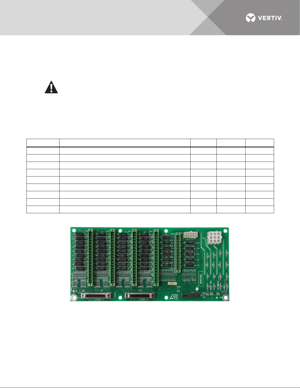
3.2 PM4 Interface Board (PIB)
The Liebert LDMF PM4 Interface Board (PIB) provides connections for the voltage and currents
of the panelboard main circuit breaker as well as the CT current for any installed large branches
or subfeed breakers (maximum of 18 CTs).
For the large branches or subfeed breakers, the nine CTs on the A side of the board are normally
associated with the A-side voltages for power calculations. The B-side CTs are normally
associated with the B-side voltages. A cross-configuration tool allows changing that association
for subfeeds.
Vertiv™ | Liebert® LDMF™ Distribution Monitoring User Manual | 4
Page 9
The 18 large branch CT inputs can also be used to monitor up to three subfeed circuit breakers.
This is configured using the configuration tool (see 5.5 - Using the Configuration Tool). The CTs
from the B side of the PIB are cross-configured to the A side so that the three subfeeds appear
within the A-side panelboard register space. The 18 large branch breakers require CT’s with 1A
secondary.
WARNING
Before connecting a large CT to the PIB, note the CT MUST have a 1A secondary.
Connecting
anything other than a 1A secondary CT will damage the PIB and the CT.
To ensure the proper current ratio and accuracy, the CTs should be purchased through
Vertiv. See Ta bl e 1 for details. Contact your local Vertiv representative or call Vertiv
Support at 800-543-2378.
Table 1 CT matrix for the Liebert LDMF
Part Number Description Phase CT Ground CT Neutral CT
539217G1-L 3-pole 0-100A Subfeed Breaker 5W CT Kit 200:1 100:1 200:1
539217G2-L 3-pole 125-225A Subfeed Breaker 5W CT Kit 500:1 100:1 500:1
539217G3-L 3-pole 250-400A Subfeed Breaker 5W CT Kit 1000:1 100:1 1000:1
539217G12-L 3-pole 125-225A Subfeed Breaker 4W CT Kit 500:1 — 500:1
539217G13-L 3-pole 250-400A Subfeed Breaker 4W CT Kit 1000:1 — 1000:1
539217G4-L 3-pole 0-100A I-Line Breaker 3W CT Kit 47" Frame 200:1 — —
539217G5-L 3-pole 125-225A I-Line Breaker 3W CT Kit 47" Frame 500:1 — —
539217G6-L 3-pole 250-400A I-Line Breaker 3W CT Kit 47" Frame 1000:1 — —
539217G7-L 1-pole 0-100A Branch Breaker CT Kit 200:1 — —
3.3 PM4 Large Interface Board (PLIB)
Vertiv™ | Liebert® LDMF™ Distribution Monitoring User Manual | 5
Page 10

The PM4 Large Interface Board (PLIB) provides voltage and current attenuation for Square-D ILine panelboards. There are 42 CT locations on each LIB for a total capacity of eight 4-wire (3
phases and neutral) or 5-wire (3 phases, neutral and ground) breakers.
WARNING
Before connecting a large CT to the PLIB, note the CT MUST have a 1A secondary.
Connecting anything other than a 1A secondary CT will damage the PLIB and the CT.
To ensure the proper current ratio and accuracy, the CTs should be purchased through
Vertiv. See Ta bl e 1 for details. Contact your local Vertiv representative or call Vertiv
Support at 800-543-2378.
Two PLIBs are supplied for a total maximum monitoring capacity of sixteen 5-wire I-Line
and/or subfeed breakers.
Vertiv™ | Liebert® LDMF™ Distribution Monitoring User Manual | 6
Page 11
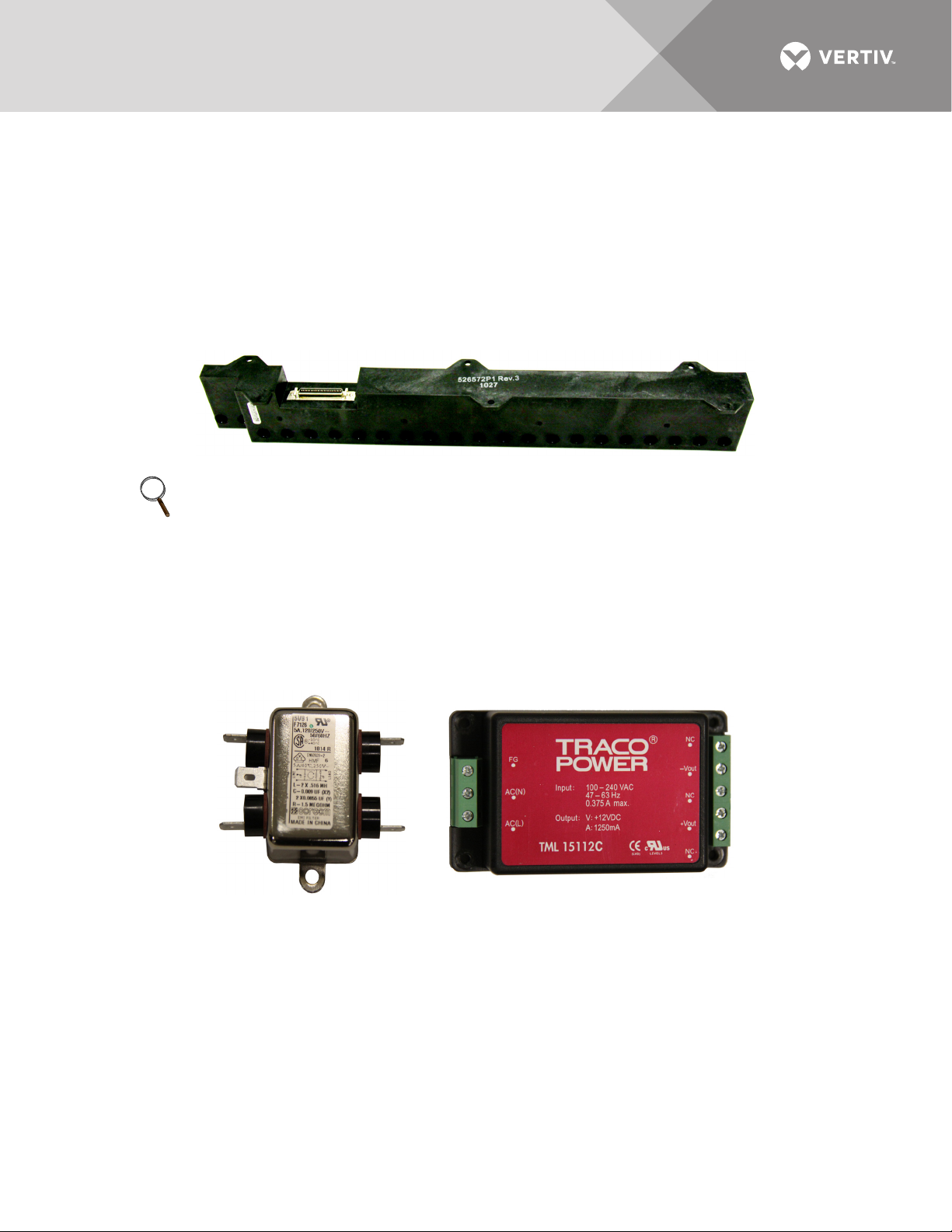
3.4 Branch Circuit Monitoring Sensor Module (BSM)
The Branch Circuit Monitoring Sensor Module (BSM)—more commonly referred to as the CT
Module—contain 21, 27 or 36 individual Current Transformers filled inside an epoxy enclosure.
Each load circuit is passed through one of the openings for branch circuit current monitoring. The
signals leave the CT module via a ribbon cable which is connected directly to the PM4 Monitor
Board (PMB) for attenuation and processing.
There are two BSM designs depending on the manufacturer of the panelboard installed:
• Utilize 1" spacing between circuits.
• Utilize 3/4" spacing between circuits.
NOTE
The diameter of each CT hole is 0.433" (11mm). Wire diameter and thickness of insulation must be
taken into account before wiring each branch circuit. Using wire that is too large may prevent the
conductor from fitting through the CT hole. Do not attempt to alter the diameter of the CT
opening.
For larger panelboards, the CT Module is designed to interlock to maintain alignment between
the breaker poles and the CT Modules.
3.5 Power Supply With EMI Filter
The power supply assembly converts 100-240VAC (+10%/-13% range) 50/60Hz into 12VDC to
provide logic level power for the PMB.
The Power Supply is fed from the line side of the panelboard main breaker. If during normal
operation the panelboard main breaker trips or is turned off, the PMB will still have power to
communicate alarms via the local display or remotely via Liebert IntelliSlot® cards.
Vertiv™ | Liebert® LDMF™ Distribution Monitoring User Manual | 7
Page 12
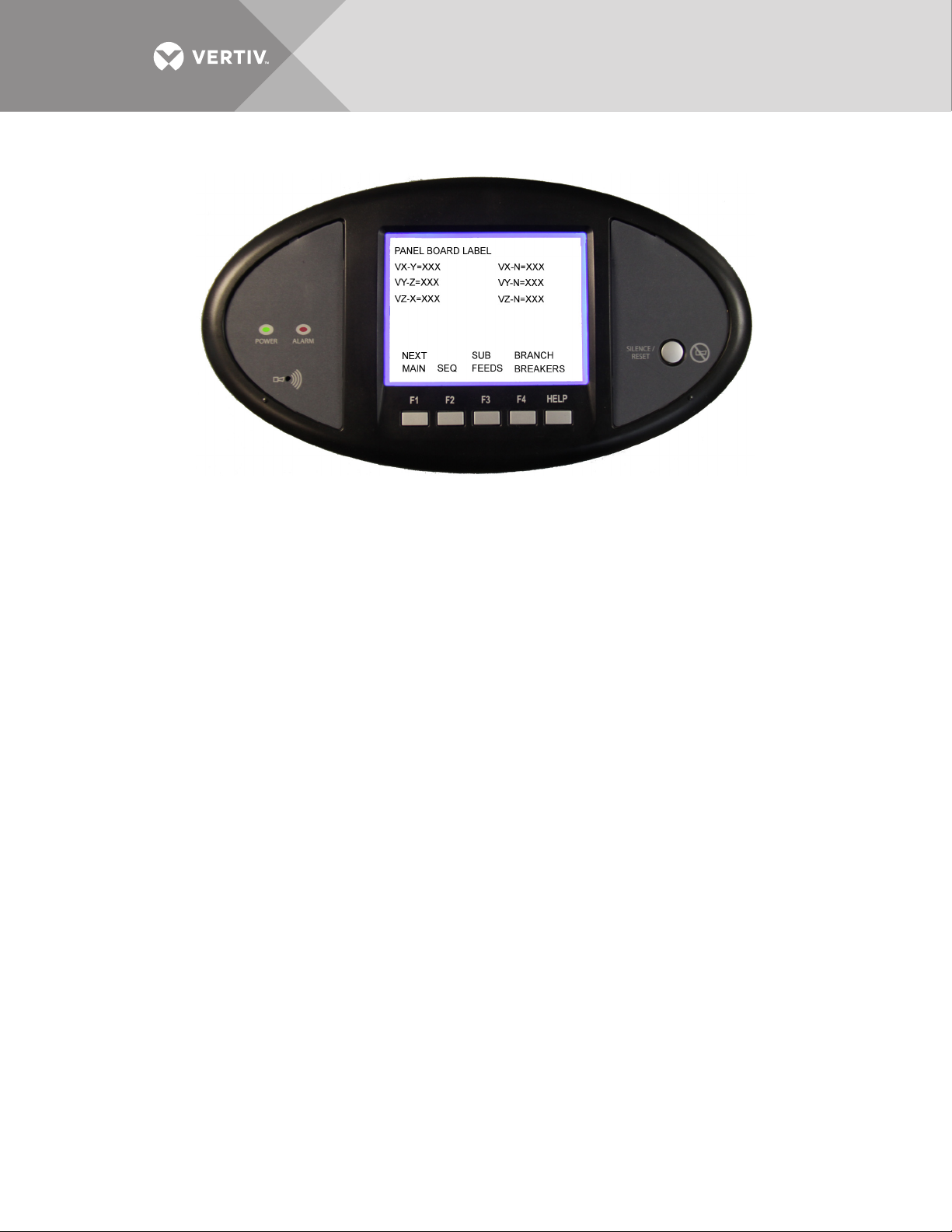
3.6 Human-Machine Interface/Display Assembly (Optional)
The LDMF allows users to view the panelboard circuit data locally through the optional display.
The user interface has function keys to scroll through and view each panelboard's data as well as
the associated branch circuits and/or subfeeds.
Along with the branch circuit data the LDMF Display also has an alarm annunciation window that
lists all active alarms. The display has an LED status indicator that changes to red in the event of
an alarm. The Silence/Reset button will silence the audible alarm when pressed once and held
until alarm is silenced. When pressed a second time, the button clears the alarm and turns off the
red LED.
Alarm thresholds cannot be added, deleted or adjusted on the local display. These functions may
be performed only by using the LDMF Configuration software, which is available for download at
the Liebert Web site. Refer to 5.3 - Downloading the Software for downloading instructions and
see 5.5 - Using the Configuration Tool for details on using the software.
Vertiv™ | Liebert® LDMF™ Distribution Monitoring User Manual | 8
Page 13

3.7 PM4 Adapter Board
• The PM4 Adapter Board (PAB) is provided with each Liebert LDMF. The PAB is typically mounted on the
back of the display, which is located on the front door of the unit. The PAB provides a customer interface to
the LDMF summary alarm contacts.
• If two Liebert LDMF systems are provided, the two PABs are connected to each other at the factory. It is
only necessary to connect to one PAB to monitor the Customer Summary Alarm; the two Liebert LDMF
units share summary alarm contacts.
• On the Liebert FPC and Liebert PPC the PAB has additional connections on TB1 that include Remote
Emergency Power Off (EPO). The field-selectable switch S1 on the PAB allows the selection for either
Manual or Auto restart. The factory default setting is Manual.
• Manual restart allows for an orderly supervised startup after power failure. The control circuit
automatically energizes the shunt trip mechanism of the main input breaker upon sensing output voltage
failure.
• Setting the switch to Auto deactivates the manual restart. In Auto restart mode, the main input breaker
does not trip due to power failure and the unit will restart when power is restored.
NOTE
The TB1 connections for customer alarms 1 - 5 are used only with the VPMP product.
Vertiv™ | Liebert® LDMF™ Distribution Monitoring User Manual | 9
Page 14
4.0 INSTALLATION
WARNING
Dangerous voltages exist in power distribution units and power conditioning units. To
ensure maximum safety, all circuits breakers in the panelboard should be removed of power
and the input feeder breaker should be turned Off and locked-out in accordance with NEC
and local/state code.
NOTE
Liebert LDMF components and any other monitoring devices should be installed only by properly
trained and qualified personnel.
This section provides instructions for installing and connecting Liebert LDMF current
transformers. If any Liebert LDMF component requires service, contact Vertiv Support at
800-543-2378 for assistance.
4.1 Installing a BSM (CT Module Assembly)
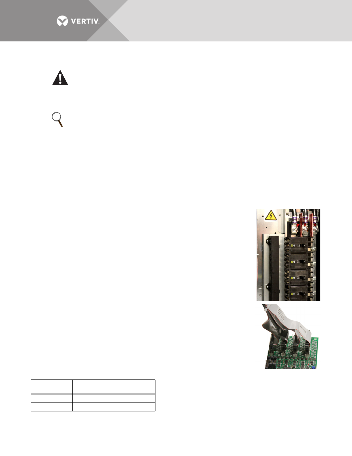
In most cases the BSM—the CT Module—is factory-installed and no further work is required. If a
CT Module must be added, it attaches easily to the side of a panelboard to monitor any
combination of 1-, 2- and 3-pole circuit breakers.
• For side-by-side panelboards (21 circuits on each side), attach one CT Module
to each side of the panelboard, ensuring that the center of the CT hole lines up
to the branch circuit breaker connection.
• For Square-D Inline panelboards (42 circuits in a row), the two CT second, lower
CT Module so that the two cutout sections line up, then attach the screws to
secure the CT Modules to the panelboard.
• For GE Inline type panelboards, the two CT Modules fit end to end. Flip the
second, lower CT Module so that the 50-pin ribbon cable connector, mounted
on the bottom of the CT Module, lines up with the hole in the panelboard
mounting bracket.
Install the circuit breakers according to the manufacturer's
documentation. Route the circuit wire through the center of the CT and
attach securely to the circuit breaker.
4.1.1 Connecting Panelboards A and B
The CT Module connects to the PMB via a 50-pin ribbon cable attached
to the back of the CT Module. Route the ribbon cable and attach to the
appropriate connector (see figure at right).
There are four connectors that are labeled for easy identification: two for
Panelboard A (A1 and A2) and two for Panelboard B (B1 and B2).
• Connect the CT module that will monitor Circuits 1-21 to the A1 or B1
connector, depending on whether the CT Module is monitoring Panelboard A
or B.
• Connect the CT module that will monitor Circuits 22-42 to the corresponding A2 or B2 connector.
Circuits
Monitored
1-21 A1 B1
22-42 A2 B2
Vertiv™ | Liebert® LDMF™ Distribution Monitoring User Manual | 10
Panelboard A
Connector
Panelboard B
Connector
Page 15
To configure the branch circuits, refer to 5.5.11 - Add a Circuit Breaker.
L
O
T
N
U
M
B
E
R
I
N
S
T
R
U
M
E
N
T
S
NOTE
• Panelboard A is either Panelboard 1 or Panelboard 3.
• Panelboard B is either Panelboard 2 or Panelboard 4 depending on which Liebert LDMF
Control Board is being configured.
4.2 Installing a Solid-Core Current Transformer
WARNING
A solid-core CT cannot be installed on a wire while current is flowing through the wire.
Damage to the burden resistor and CT will occur. Power must be removed before installing
and/or removing any CT. CT’s should be installed only by properly trained qualified
electricians.
The CT for the panelboard main input circuit breaker is hard-wired to the connectors. Removing
CT wires from the connector requires a pin extraction tool.
Contact Vertiv Support at 800-543-2378 for assistance.
NOTE
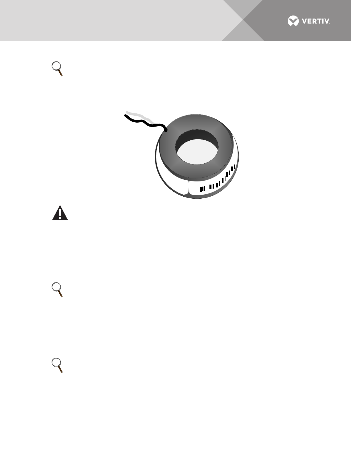
When replacing or installing a CT, ensure that the replacement CT has a secondary rating of 1A—
for example, 100:1, 200:1, 500:1 or 1000:1. Using a higher-rated CT—for example, 100:5 or 500:5will damage the burden resistors on the PIB board.
Typically the three-phase and neutral wires utilize a CT rating of 100:1, 200:1 500:1 or 1000:1, while
the ground wire utilizes a CT rating of 100:1.
Route the circuit wire through the core of the CT and wire-tie the CT to the cable. Refer to the
manufacturer's documentation for proper orientation to ensure accurate readings.
NOTE
When installing CT’s for a large branch circuit breaker or subfeed, verify which monitoring board
is installed.
• A PIB can support up to three subfeeds,.
• One LIB can support up to eight output and/or subfeed breakers.
• Two LIB boards are provided to support up to 16 output and/or subfeed breakers.
Vertiv™ | Liebert® LDMF™ Distribution Monitoring User Manual | 11
Page 16
4.3 Installing a Current Transformer on the PIB Interface Board
If subfeed breakers are ordered with the unit, the phase,
neutral and ground CTs are wired to the Interface
Board.The CTs will be zip-tied inside the equipment for the
electrician to install on each conductor when the
conductors are wired to the subfeed/large branch breaker.
The ground and neutral CTs for each factory-supplied
subfeed or large breaker are factory-installed and wired.
CTs have a white or H1 that depicts how to position the CT
on the cable to ensure accurate readings. The white dot or
H1 must face toward the source when installing the CT on
the phase cables. The neutral conductor CTs are placed in
the opposite direction, with the marking faced toward the load. Route the conductors through the
core of the CTs and wire-tie the CT to the cable to ensure the CT stays in place.
If subfeed breakers are installed in the field, up to five CTs may be installed (three phases, neutral
and ground). The neutral and ground CTs may be omitted if monitoring of neutral and ground is
not required. The 5-wire CT kits will be shipped separately and grouped together with each CT
with a label indicating whether it is a phase CT, neutral CT or ground CT.
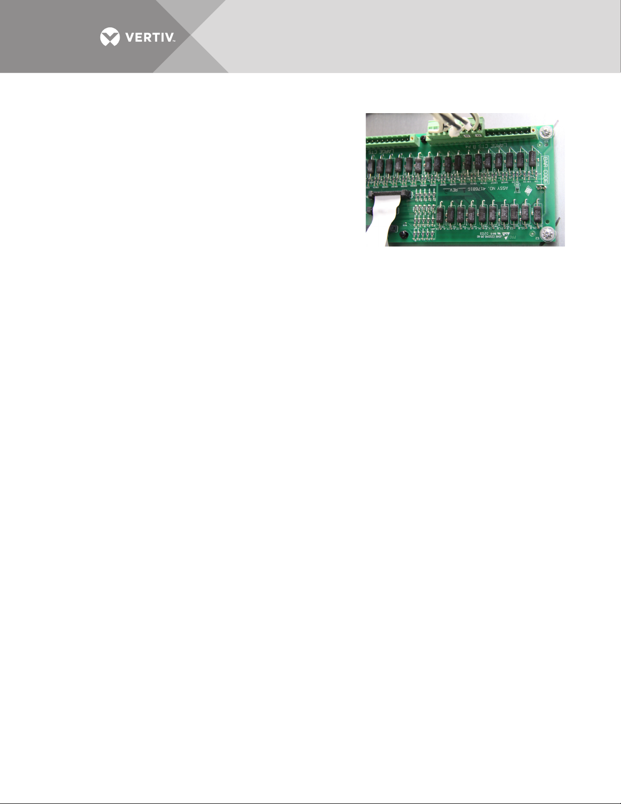
There are two 18-pin terminal blocks on the Interface Board for large branch circuit breakers
and/or subfeeds-one for Panelboard A and one for Panelboard B.
The circuit board is marked with a triangle to indicate Pin 1. Pin 1 should be used for the white wire
of CT1 (Phase A). The black wire should be connected to Pin 2. The same pattern will follow for
the remaining CTs.
After all CTs are installed, use the Configuration tool to label and set alarm parameters. To
configure the Liebert LDMF, see 5.5.11 - Add a Circuit Breaker.
If the Power Distribution Center is supplied with optional isolated ground, the isolated ground
circuit can be monitored by the Liebert LDMF. Usually the CT is already installed and wired to the
Large Branch Terminal Block at the factory. If not, perform the following steps:
(For Isolated Ground CT Installation only)
• Connect the isolated ground CT to Pins 17 and 18 on the two 18-pin terminal blocks on the Interface
Board.
• Connect the isolated ground CT white wire to Pin 17 and the CT black wire to Pin 18.
Refer to the following example and Tab le 2 for wiring configuration details.
Example: When installing a subfeed breaker where the three phases, neutral and ground will be
monitored, the CTs should be wired as follows:
Vertiv™ | Liebert® LDMF™ Distribution Monitoring User Manual | 12
Page 17
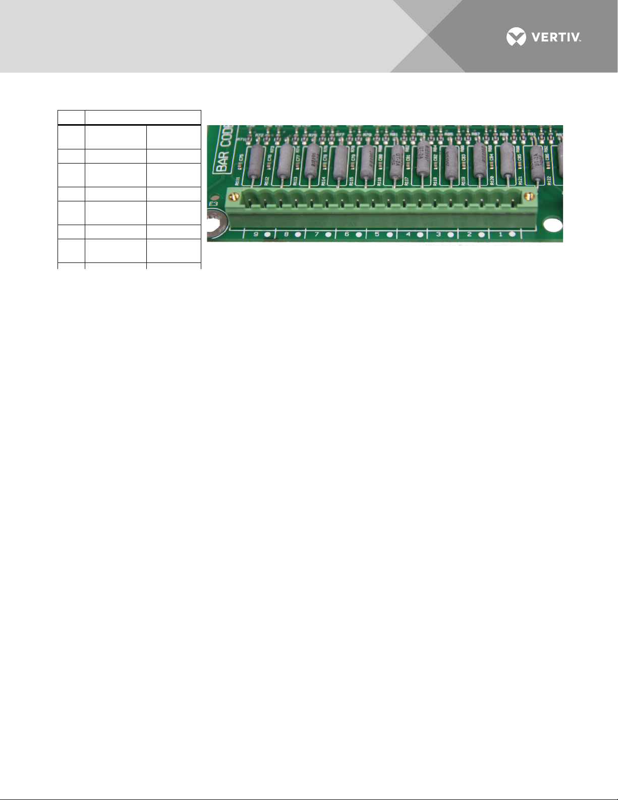
If a second subfeed or large branch breaker will be installed, the same pattern will continue. Pins
Table 2 Large branch breaker CT wiring
Pin Wiring
1Phase A CT
White
wire
2 Phase A CT Black wire
3Phase B CT
White
wire
4 Phase B CT Black wire
5Phase C CT
White
wire
6 Phase C CT Black wire
7Neutral CT
White
wire
11 and 12 will be Phase A CT for the second breaker, Pins 13 and 14 will be Phase B CT and so on.
Vertiv™ | Liebert® LDMF™ Distribution Monitoring User Manual | 13
Page 18
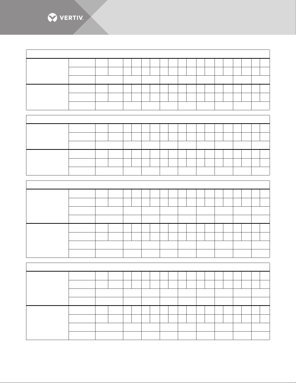
Table 3 CT Table for Interface Board
Configuration 1: Four Modules
Position 9 • 8 • 7 • 6 • 5 • 4 • 3 • 2 • 1 •
Connector P3 (A)
Connector P4 (B)
Configuration 2: Two Modules With Large Branch Breaker CT’s
Connector P3 (A)
Connector P4 (B)
Configuration 3: Four Modules With Two 5-Wire Subfeed Breaker CT’s
Connector P3 (A)
Wire Color B W BWBWBWBWBWBWBWBW
CT CT9 or IG CT8 CT7 CT6 CT5 CT14 CT3 CT2 CT1
Position
Wire Color B W BWBWBWBWBWBWBWBW
CT CT18 or IG CT17 CT16 CT15 CT14 CT13 CT12 CT11 CT10
Position 9 • 8 • 7 • 6 • 5 • 4 • 3 • 2 • 1 •
Wire Color B W BWBWBWBWBWBWBWBW
CT LB9 or IG LB8 LB7 LB6 LB5 LB4 LB3 LB2 LB1
Position
Wire Color B W BWBWBWBWBWBWBWBW
CT LB18 or IG LB17 LB16 LB15 LB14 LB13 LB12 LB11 LB10
Position 9 • 8 • 7 • 6 • 5 • 4 • 3 • 2 • 1 •
Wire Color B W BWBWBWBWBWBWBWBW
CT LB5 LB4 LB3 LB2 LB1
9•8•7•6•5•4•3•2•1•
9•8•7•6•5•4•3•2•1•
Phase IG G1 N1 C1 B1 A1
Position 9 • 8 • 7 • 6 • 5 • 4 • 3 • 2 • 1 •
Connector P4 (B)
Configuration 4: Four Modules With Three 5-Wire Subfeed Breaker CT’s
Connector P3 (A)
Connector P4 (B)
Wire Color B W BWBWBWBWBWBWBWBW
CT LB10 LB9 LB8 LB7 LB6
Phase IG G2 N2 C2 B2 A2
Position 9 • 8 • 7 • 6 • 5 • 4 • 3 • 2 • 1 •
Wire Color B W BWBWBWBWBWBWBWBW
CT LB12 LB11 LB5 LB4 LB3 LB2 LB1
Phase IG G3 N3 G1 N1 C1 B1 A1
Position 9 • 8 • 7 • 6 • 5 • 4 • 3 • 2 • 1 •
Wire Color B W BWBWBWBWBWBWBWBW
CT LB13 LB12 LB11 LB10 LB9 LB8 LB7 LB6
Phase IG C3 B3 A3 G2 N2 C2 B2 A2
Vertiv™ | Liebert® LDMF™ Distribution Monitoring User Manual | 14
Page 19
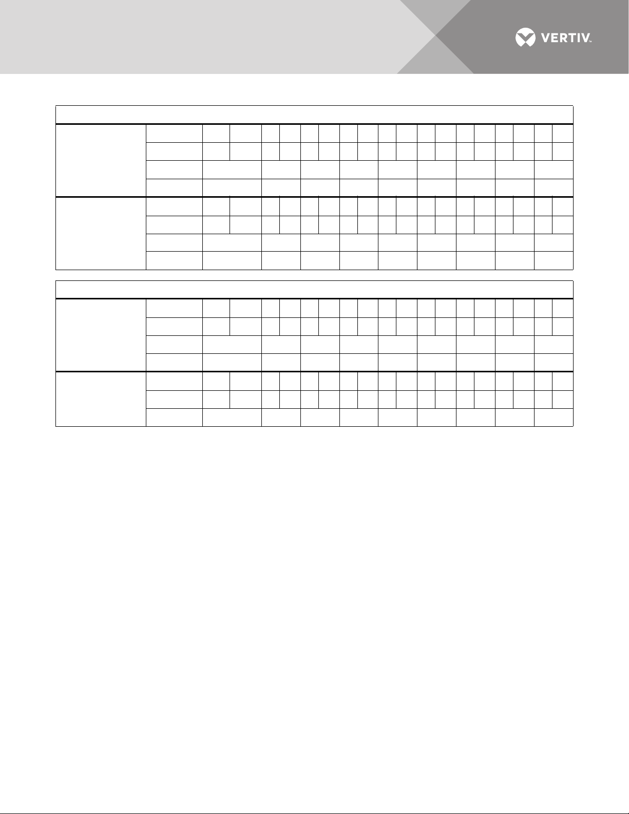
Table 3 CT Table for Interface Board (continued)
Configuration 5: Four Modules With Six 3-Wire Subfeed Breaker CT’s
Position 9 • 8 • 7 • 6 • 5 • 4 • 3 • 2 • 1 •
Connector P3 (A)
Wire Color B W BWBWBWBWBWBWBWBW
CT LB9 LB8 LB7 LB6 LB5 LB4 LB3 LB2 LB1
Phase C3 B3A3C2B2A2C1 B1 A1
Position 9 • 8 • 7 • 6 • 5 • 4 • 3 • 2 • 1 •
Wire Color B W BWBWBWBWBWBWBWBW
Connector P4 (B)
CT LB18 LB17 LB16 LB15 LB14 LB13 LB12 LB11 LB10
Phase C6 B6A6C5B5A5C4B4A4
Configuration 6: Three Modules With Nine Large Branch Breaker CT’s
Position 9 • 8 • 7 • 6 • 5 • 4 • 3 • 2 • 1 •
Wire Color B W BWBWBWBWBWBWBWBW
Connector P3 (A)
CT LB9 or IG LB8 LB7 LB6 LB5 LB4 LB3 LB2 LB1
Phase C3 B3A3C2B2A2C1 B1 A1
Position 9 • 8 • 7 • 6 • 5 • 4 • 3 • 2 • 1 •
Connector P4 (B)
Wire Color B W BWBWBWBWBWBWBWBW
CT C6 B6 A6 C5 B5 A5 C4 B4 A4
W = White
B = Black
IG = Isolated Ground CT
LB = Large Branch Breaker CT
A = A Phase CT
B = B Phase CT
C = C Phase CT
N = Neutral CT
G = Ground CT
Vertiv™ | Liebert® LDMF™ Distribution Monitoring User Manual | 15
Page 20
4.4 Connecting a Current Transformer to the PM4 Large Interface Board (PLIB)
PLIB can monitor eight 4-wire or 5-wire output/subfeed breakers. Two LIB boards are provided to
support up to 16 output and/or subfeed breakers. If subfeed breakers are ordered with the unit,
the phase CTs are installed and wired to the PLIB. The neutral and ground CTs are also factorysupplied and wired to the PLIB as required.
CTs have a white dot or H1 marking that depicts how to position the CT to ensure accurate
readings. The white dot or H1 marking must face toward the load when installing the CT on the
ground and neutral cable. The phase CT's are placed in the opposite direction, with the marking
faced toward the source. Route the neutral and ground cable through the core of the specified CT
and wire-tie the CT to the cable.
If subfeed breakers are installed in the field, up to five CTs may be installed to monitor a subfeed
breaker (three phases, neutral and ground). The neutral and ground CTs may be omitted if
monitoring of neutral and ground is not required.
The designators on the PLIB are different from those on the Interface Board.
• CT1 (Phase A white wire) begins on TB1 CT1+ and the black wire connects to CT1-.
• The Ground CT for the first subfeed/output circuit breaker connects to TB4 CT35.
The designators on the PLIB are different from those on the Interface Board.
• CT1 (Phase A white wire) begins on TB1 CT1+ and the black wire connects to CT1-.
• The Ground CT for the first subfeed/output circuit breaker connects to TB4 CT35.
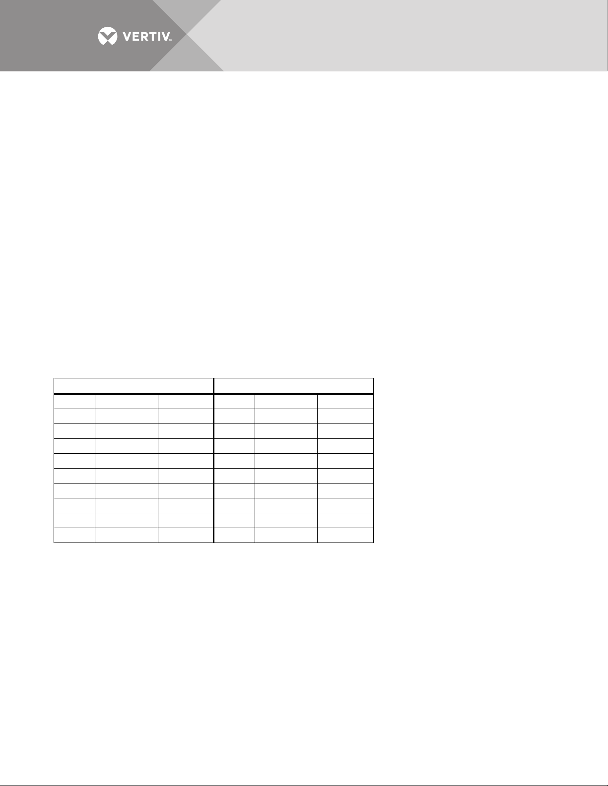
First Breaker Second Breaker
CT1+ Phase A CT White wire CT5+ Phase A CT White wire
CT1 Phase A CT Black wire CT5 Phase A CT Black wire
CT2+ Phase B CT White wire CT6+ Phase B CT White wire
CT2 Phase B CT Black wire CT6 Phase B CT Black wire
CT3+ Phase C CT White wire CT7+ Phase C CT White wire
CT3 Phase C CT Black wire CT7 Phase C CT Black wire
CT4+ Neutral CT White wire CT8+ Neutral CT White wire
CT4 Neutral CT Black wire CT8 Neutral CT Black wire
CT35+ Ground CT White wire CT36+ Ground CT White wire
CT35 Ground CT Black wire CT36 Ground CT Black wire
If more output or subfeed CTs must be installed, continue in the same pattern shown above.
• Connect the Phase A CT for the second breaker on CT5 (white wire to CT5+, black to CT5-).
• Connect the Ground CT for the second breaker to CT36 (white wire to CT36+, black to CT36-).
• Continue the same pattern until all CT connections are used or there are no more outputs or subfeed CTs
to add.
Vertiv™ | Liebert® LDMF™ Distribution Monitoring User Manual | 16
Page 21
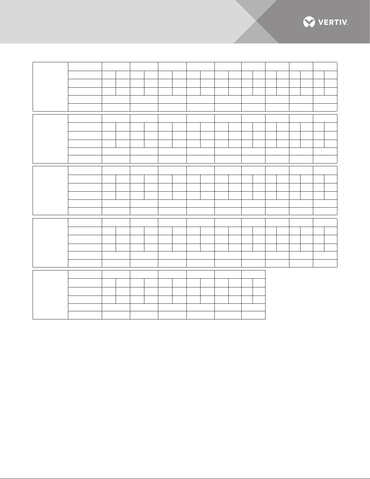
Table 4 CT Table for PM4 Large Interface Board #1
PCB Label CT9 CT8 CT7 CT6 CT5 CT4 CT3 CT2 CT1
Pins 18 17 16 15 14 13 12 11 10 9 8 7 6 5 4 3 2 1
Connector
TB1
Connector
TB2
Connector
TB3
Connector
TB4
Wire ColorBWBWBWBWBWBWBWBWBW
CT CT9 CT8 CT7 CT6 CT5 CT4 CT3 CT2 CT1
Phase A3 N2 C2 B2 A2 N1 C1 B1 A1
PCB Label CT18 CT17 CT16 CT15 CT14 CT13 CT12 CT11 CT10
Pins 18 17 16 15 14 13 12 11 10 9 8 7 6 5 4 3 2 1
Wire ColorBWBWBWBWBWBWBWBWBW
CT CT18 CT17 CT16 CT15 CT14 CT13 CT12 CT11 CT10
Phase B5 A5 N4 C4 B4 A4 N3 C3 B3
PCB Label CT27 CT26 CT25 CT24 CT23 CT22 CT21 CT20 CT19
Pins 18 17 16 15 14 13 12 11 10 9 8 7 6 5 4 3 2 1
Wire ColorBWBWBWBWBWBWBWBWBW
CT CT27 CT26 CT25 CT24 CT23 CT22 CT21 CT20 CT19
Phase C7 B7 A7 N6 C6 B6 A6 N5 C5
PCB Label CT36 CT35 CT34 CT33 CT32 CT31 CT30 CT29 CT28
Pins 18 17 16 15 14 13 12 11 10 9 8 7 6 5 4 3 2 1
Wire Color B W B W B WBWBWBWBW
CT CT2 CT1 NONE NONE CT32 CT31 CT30 CT29 CT28
Phase G2 G1 N8 C8 B8 A8 N7
- + - + - + - + - +-+-+-+-+
- + - + - + - + - +-+-+-+-+
- + - + - + - + - +-+-+-+-+
- + - + - + - + - +-+-+-+-+
Connector
TB5
W = White
B = Black
PCB Label CT42 CT41 CT40 CT39 CT38 CT37
Pins 12 11 10 9 8 7 6 5 4 3 2 1
-+-+-+-+-+-+
Wire ColorBWBWBWBWBWBW
CT CT8 CT7 CT6 CT5 CT4 CT3
Phase G8 G7 G6 G5 G4 G3
A = A Phase
B = B Phase
C = C Phase
N = Neutral
G = Ground
Vertiv™ | Liebert® LDMF™ Distribution Monitoring User Manual | 17
Page 22
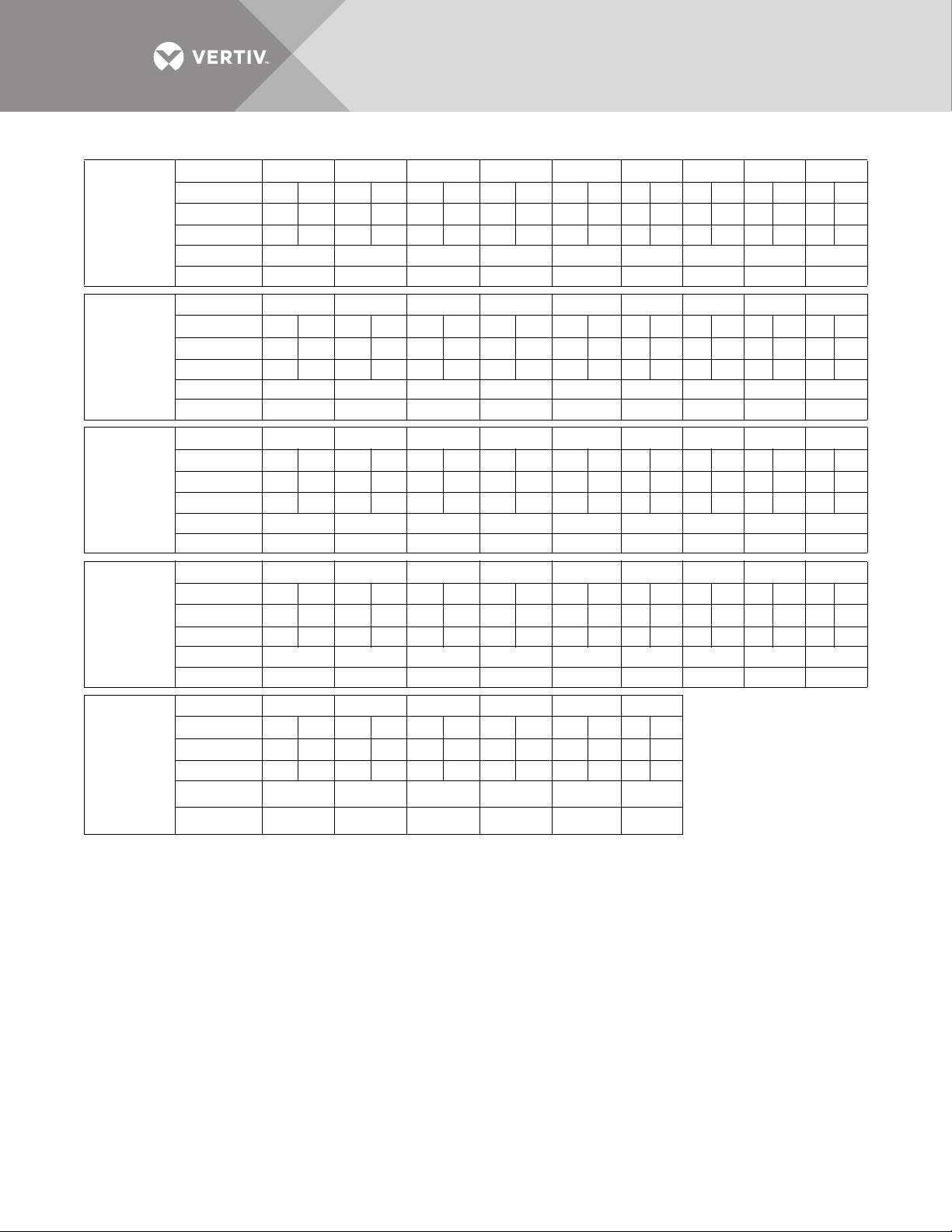
Table 5 CT Table for PM4 Large Interface Board #2
PC Label CT9 CT8 CT7 CT6 CT5 CT4 CT3 CT2 CT1
Pins 18 17 16 15 14 13 12 11 10 9 8 7 6 5 4 3 2 1
Connector
TB1
Connector
TB2
Connector
TB3
Connector
TB4
Wire ColorBWBWBWBWBWBWBWBWBW
CT CT41 CT40 CT39 CT38 CT37 CT36 CT35 CT34 CT33
Phase A11 N10 C10 B10 A10 N9 C9 B9 A9
PC Label CT18 CT17 CT16 CT15 CT14 CT13 CT12 CT11 CT10
Pins 18 17 16 15 14 13 12 11 10 9 8 7 6 5 4 3 2 1
Wire ColorBWBWBWBWBWBWBWBWBW
CT CT50 CT49 CT48 CT47 CT46 CT45 CT44 CT43 CT42
Phase B13 A13 N12 C12 B12 A12 N11 C11 B11
PC Label CT27 CT26 CT25 CT24 CT23 CT22 CT21 CT20 CT19
Pins 18 17 16 15 14 13 12 11 10 9 8 7 6 5 4 3 2 1
Wire ColorBWBWBWBWBWBWBWBWBW
CT NONE NONE NONE NONE NONE NONE NONE CT52 CT51
Phase N13 C13
PC Label CT36 CT35 CT34 CT33 CT32 CT31 CT30 CT29 CT28
Pins 18 17 16 15 14 13 12 11 10 9 8 7 6 5 4 3 2 1
Wire Color B W B W B WBWBWBWBW
CT CT10 CT9 NONE NONE NONE NONE NONE NONE NONE
Phase G10 G9
- + - + - + - + - +-+-+-+-+
- + - + - + - + - +-+-+-+-+
- + - + - + - + - +-+-+-+-+
- + - + - + - + - +-+-+-+-+
Connector
TB5
W = White
B = Black
PC Label CT42 CT41 CT40 CT39 CT38 CT37
Pins 12 11 10 9 8 7 6 5 4 3 2 1
-+-+-+-+-+-+
Wire ColorBWBWBWBWBWBW
CT NONE NONE NONE CT13 CT12 CT11
Phase G13 G12 G11
A = A Phase
B = B Phase
C = C Phase
N = Neutral
G = Ground
Vertiv™ | Liebert® LDMF™ Distribution Monitoring User Manual | 18
Page 23
5.0 OPERATION
The Liebert LDMF is a factory-installed option to provide monitoring of the main breaker, branch
circuit breakers and subfeed breakers. It may be installed in the Liebert PPC, Liebert FDC, Liebert
FPC. Liebert RX and the Liebert RDC.
Software available on the Liebert Web site (see 5.3 - Downloading the Software) can be
installed on a desktop or laptop computer (PC) to monitor status and configure breaker
parameters and alarm setpoints. These monitoring and configuration functions are described in
5.4 - Using the Monitor Tool (Used Only for Startup and Diagnostics) and 5.5 - Using the
Configuration Tool.
The Liebert LDMF has an optional local display in conjunction with the remote monitoring
capability. The display allows end users to view the panelboard main information as well as each
individual branch circuit breaker and/or subfeed data. Alarm status may also be viewed from the
local display for up-to-date breaker status.
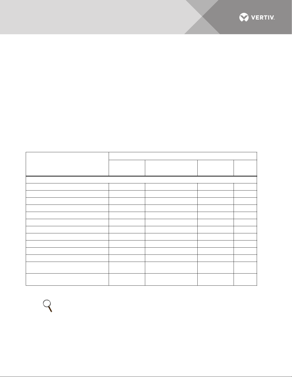
The Liebert LDMF monitors and displays the parameters listed in Table 6.
Table 6 Parameters monitored for breakers
Displayed and monitored for each:
Panelboard
Parameters
Vol tag e
Line-to-Line — 4 — —
Line-to-Neutral — 4 — —
Phase Current 4 4 4 4
Neutral Current — 4 4 4
Ground Current — 4 4 4
kVA — 4 4 4
kW 4444
kW-Hours 4 4 4 4
Percent Load 4444
Power Factor — 4 4 4
Crest Factor — 4 4 4
Voltage Total Harmonic Distortion
(THD)
Current Total Harmonic Distortion
(THD)
Branch
Circuit Breaker
—4 44
—4 44
Panelboard Main
Circuit Breaker and
SqD I-Line Panelboard
SqD I-Line
Panelboard
Circuit Breaker
Subfeed
Circuit
Breaker
Circuit identification and status of each breaker are also displayed.
NOTE
Before making any changes to an existing configuration or uploading a file to another Liebert
LDMF system, make a note of the Software Address. When overwriting an existing configuration
file due to changes, modifications or breaker addition/deletion, the Software Address will revert
to the value of the file that is loaded. This can lead to incorrect Software Addresses causing
Modbus communication errors.
Vertiv™ | Liebert® LDMF™ Distribution Monitoring User Manual | 19
Page 24
5.1 Alarms
The Liebert LDMF constantly monitors electrical data for each breaker and subfeed. When the
unit detects an alarm condition, it annunciates and displays alarm messages via the Monitor
program (see 5.4 - Using the Monitor Tool (Used Only for Startup and Diagnostics)) as well as
showing the alarm on the local display (if installed).
Alarms must be manually reset after the alarm condition has been corrected and may be reset
through Modbus or by pressing the alarm Silence/Reset button on the front display assembly.
To facilitate troubleshooting:
• All alarms are stored in non-volatile memory to protect against erasure by a power outage.
All alarm thresholds for monitored parameters are adjustable by using the Configuration tool to
match site requirements (see 5.5 - Using the Configuration Tool).
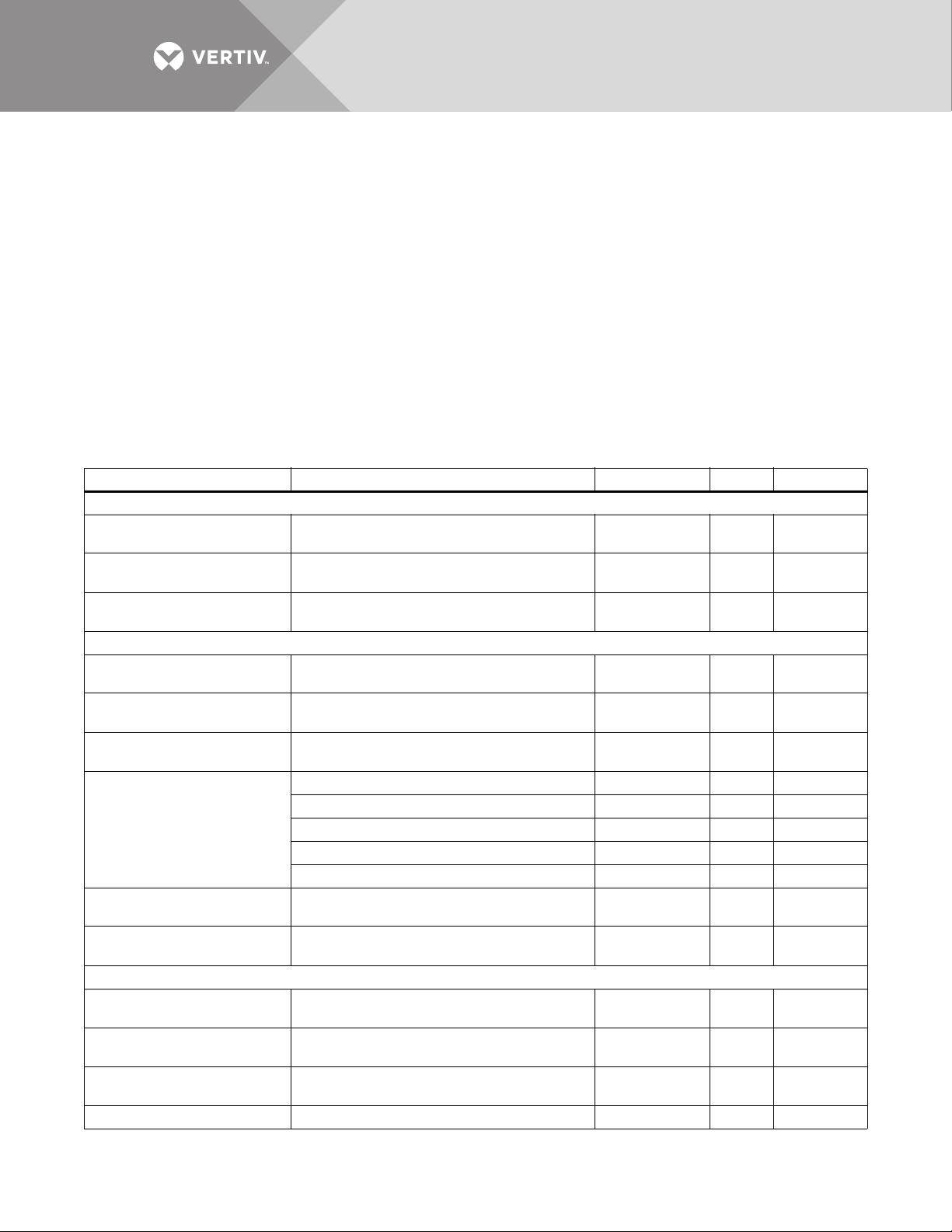
Tab le 7 shows the types of alarms for the various types of breakers, along with a description,
factory default setpoints and allowable range for each.
Table 7 Alarm conditions and factory setpoints
Alarm Description Default setting Range Comments
Branch Breakers
• Overcurrent Warning Current exceeds 75% of breaker amps 15A
• Overcurrent Alarm Current exceeds 80% of breaker amps 16A
• Low Current Alarm Minimum current level of a branch breaker
Panelboard Main Breaker and SqD I-Line Panelboard
• Phase Overcurrent Warning Current exceeds 75% of breaker amps 170A
• Phase Overcurrent Alarm Current exceeds 80% of breaker amps 180A
• Neutral Overcurrent Alarm Current exceeds 95% of breaker amps 214A
Current exceeds 5 amps (15-125kVA) 5A 1-100A —
Current exceeds 10 amps (150-225kVA) 10A 1-100A —
• Ground Overcurrent Alarm
• Overvoltage Alarm
• Undervoltage Alarm
Subfeed Breakers and I-Line Output Breakers
• Phase Overcurrent Warning Current exceeds 75% of breaker amps 170A
• Phase Overcurrent Alarm Current exceeds 80% of breaker amps 180A
• Low Current Warning Minimum current level of a branch breaker
• Ground Overcurrent Alarm Current exceeds 5 amps 5A 1-100A —
Current exceeds 15 amps (300kVA) 15A 1-100A —
Current exceeds 20 amps (450kVA) 20A 1-100A —
Current exceeds 25 amps (800kVA) 25A 1-100A —
At least one of the line-to-line voltages
exceeds +6% of nominal
At least one of the line-to-line or line-toneutral voltages falls below -13% of nominal
0% (disables
the alarm)
—0-50%
—0-50%
0% (disables
the alarm)
0-
200%
0-
200%
0-70% —
0-
200%
0-
200%
0-
200%
0-
200%
0-
200%
0-70% —
0% Disables
—
0% Disables
—
—
100% to
Disable
100% to
Disable
0% Disables
—
Vertiv™ | Liebert® LDMF™ Distribution Monitoring User Manual | 20
Page 25

Table 7 Alarm conditions and factory setpoints
Alarm Description Default setting Range Comments
Summary Alarm
Panelboard Summary Alarm
Detects and annunciates upon occurrence of
any alarm
Detects and annunciates upon occurrence of
branch or panelboard main breaker alarm
———
———
Vertiv™ | Liebert® LDMF™ Distribution Monitoring User Manual | 21
Page 26
5.2 Communication
LDMF SETUP
THE LDMF DOCUM ENTATION TOO LKIT WHICH
INCLUDES THE USER’S MANUAL
CONFIGURAT ION SOFTWARE AND MODBUS
REGISTRY CAN BE DOWNLOADED AT THE
FOLLOWING WEB ADDRESS
HTTP://WWW.LIEBERT .COM/SERVICESUPPORT
_PAGES/SERVICESUPPORT. ASPX?X=SOFTWA
RE_DOWNLO ADS
528046P1 Rev 3
LDMF SETUP
THE LDMF DOCUM ENTATION TOO LKIT WHICH
INCLUDES THE USER’S MANUAL
CONFIGURATION SOFTWARE AND MODBUS
REGISTRY CAN BE DOWNLOADED AT THE
FOLLOWING WEB ADDRESS
HTTP://WWW.LIEBERT .COM/SERVICESUPPORT
_PAGES/SERVICESUPPORT. ASPX?X=SOFTWA
RE_DOWNLO ADS
528046P1 Rev 3
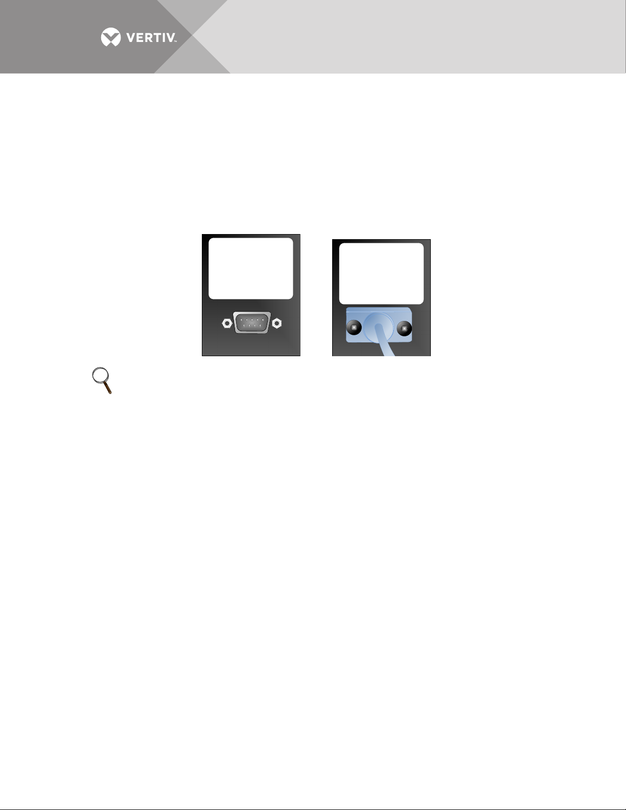
Connecting locally to the Liebert LDMF Monitoring option requires a female-to-female (F-F) DB9
null modem cable. There will be an external port on the Liebert Power product labeled LDMF
SETUP. Connect the DB9 null modem cable to a local PC. Once connected you may run any of the
provided software tools that can be downloaded from the Liebert Web site (see 5.3 -
Downloading the Software).
5.2.1 LDMF Setup Port Connection
The local LDMF Setup port is not intended to be a service terminal or hyperterminal connection.
It is intended only for use of the Liebert LDMF software tools provided.
NOTE
The images above are for illustration only. The location of the external port may vary.
5.2.2 Modbus Connection
Use the Modbus port for remote communication. The Liebert LDMF supports two-wire RS-485
and Ethernet connections (customer-installed).
To connect to the Modbus port:
• Look for Connector RS-485 on the Liebert IntelliSlot™ IS-UNITY-DP or IS-485S card for Modbus 485, or IS-
• Refer to the following figure for proper connection points.
IPBMS or IS-UNITY-DP card for Modbus IP.
Vertiv™ | Liebert® LDMF™ Distribution Monitoring User Manual | 22
Page 27
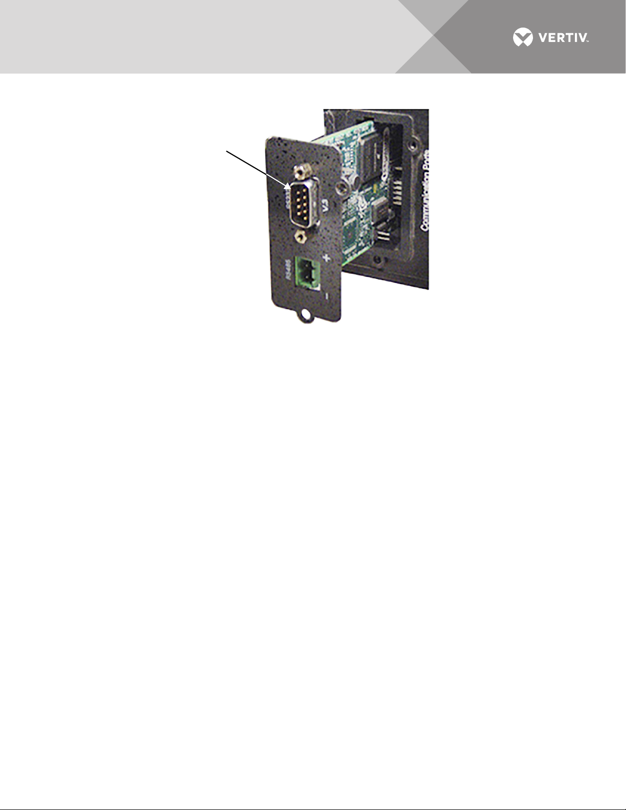
Figure 1 RS-232 port
RS-232 Port
Vertiv™ | Liebert® LDMF™ Distribution Monitoring User Manual | 23
Page 28

5.3 Downloading the Software
The Liebert LDMF has three software tools for monitoring, configuration and firmware updates:
• Monitoring - see 5.4 - Using the Monitor Tool (Used Only for Startup and Diagnostics)
• Configuration - see 5.5 - Using the Configuration Tool
These programs may be downloaded at no charge or license fee at the Liebert Web
site,www.vertivco.com. Under Service and Support, choose Software Downloads.
• Click on the link for the LDMF - mm/yyyy Toolkit:
where mm/yyyy is the month and year of the update—for example, 08/2016
Note: There are two versions of Liebert Distribution Monitoring software.
Be sure to select the LDMF version, which is for units with a setup port labeled LDMF Setup.
Do NOT choose the Liebert Distribution Monitoring (LDM) Tool Kit. (The LDM Tool Kit is used on units with
a setup port labeled LDM Setup.)
• Save the file to a computer (PC) and extract the contents.
NOTE
The software may be updated and changed without any notification. Check the Web site
regularly to ensure the software is up-to-date.
5.4 Using the Monitor Tool (Used Only for Startup and Diagnostics)
The Monitor tool supports a local connection through the LDMF Setup port. The tool displays the
following information:
• Main input voltage and currents
•Total power
• Individual branch circuit breaker currents
• System clock (date and time)
•Reset kWh function
5.4.1 Starting the Monitor Tool
• If needed, download the latest version of the software (see 5.3 - Downloading the Software).
• Run the executable file Monitor-xx.exe (where xx is the latest version) to start the Monitor tool.
• In the Connect window, select the appropriate COM port, shown below left. The dialog box lists available
ports only. If a port is in use, it does not appear in the list.
•Click Connect.
Vertiv™ | Liebert® LDMF™ Distribution Monitoring User Manual | 24
Page 29
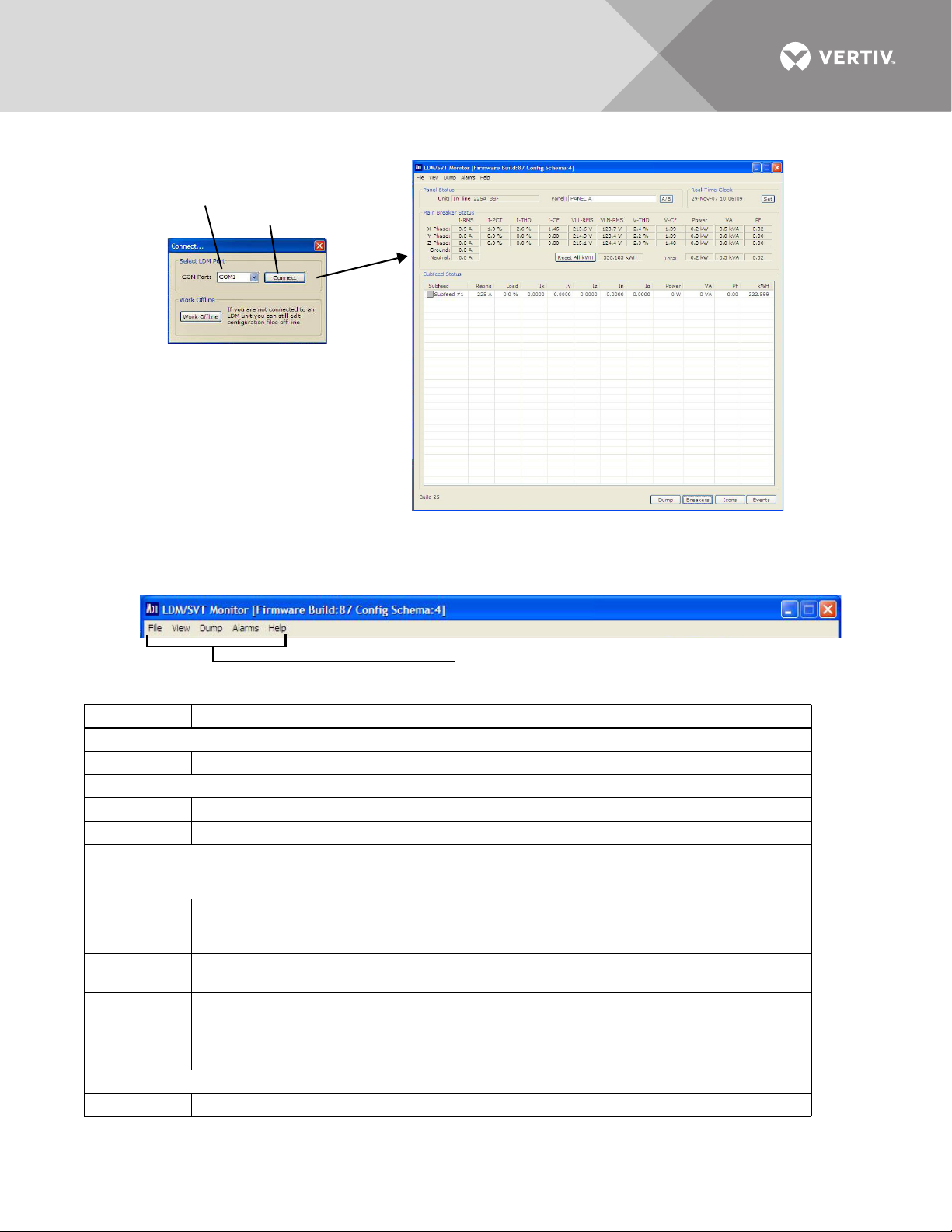
• The Monitoring main window, below right, opens after communication is established.
Connect
COM port
Menu options
5.4.2 Monitor Menu Options
The Monitor window has a menu bar at the top with a drop-down list of options for each menu.
Tab le 8 summarizes the options available in these menus.
Table 8 Monitor Menu Options
Menu Option Function
File Menu
• Exit Terminates the monitoring session and closes the Monitor program.
View Menu
• Breakers Updates the status of all branch breakers for the selected panel in the Breaker Status area.
• Subfeeds Updates the status of all subfeed breakers for the selected panel in the Breaker Status area.
Alarms Menu
Choose one of three options—Raw, Filtered or Latched—to specify how alarms are displayed.
Note that alarms sent over Modbus are latched independent of changes performed in the Alarms menu.
•Raw The raw alarm state is the instantaneous state of the alarm. It is not filtered and has no hysteresis.
•Filtered The filtered alarm uses the hysteresis interval to suppress transient alarms. A filtered alarm is
• Latched Latched alarms behave like filtered alarms that get stuck on. A latched alarm stays active until
• Clear All Clears all latched alarms for the selected panel. Any alarm condition that is still active is latched
Help Menu
• About Displays information about Liebert Distribution Monitoring.
When Raw is selected, an alarm is active whenever the latest reading exceeds the set point and is
cleared as soon as the reading returns to a level within the set point range.
cleared after the alarm condition remains cleared for longer than the hysteresis interval.
the alarm is manually cleared.
again after the hysteresis interval passes.
Vertiv™ | Liebert® LDMF™ Distribution Monitoring User Manual | 25
Page 30
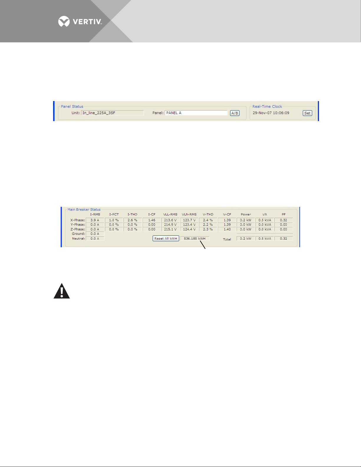
5.4.3 Panel Status and Real-Time Clock
Metered energy usage for the panel
The Panel Status area displays:
• The name of the Liebert LDMF in the Unit box.
• The currently selected panel in the Panel box.
To choose a different panel, click on the panel name or the A/B button. If the selected panel has any active
alarms, the panel name appears in white text with a red background.
The Real-Time Clock displays the time as stored in the Liebert LDMF unit. The time will not
display correctly if the time zone is incorrect in the PC. If the time displayed is incorrect and the
problem is not caused by a time-zone configuration problem:
• Click the Set button to force the real-time clock to synchronize with the time set on the PC.
5.4.4 Main Breaker Status
The Main Breaker Status area displays RMS current, percent load (PCT), total harmonic
distortion (THD), crest factor (CF), line-to-line voltage (VLL-RMS), line-to-neutral voltage
(VLN-RMS), average power (Power), VA and power factor (PF) for each input phase. If any phase
voltage or current is in alarm, the associated field displays white text with a red background.
The metered energy usage for the panel is also displayed in kilowatt hours (kWh), as shown
above. To clear all metering information, click the Reset All kWh button.
CAUTION
Exercise care before using the Reset All kWh button, which resets the kWh usage for the
main breaker as well as all branch breakers and subfeed breakers on the panel.
5.4.5 Breaker Status
The Breaker Status area displays detailed status for every branch or subfeed breaker on the
selected panel. The information may appear in table format or in a list with icons indicating status,
depending on whether the Tab le or Icons button is active (see 5.4.6 - Mode Buttons).
The example below left shows the table format with details for each branch breaker: type and
rating, percent load, individual phase current in amps (I1, I2, I3), power, apparent power (VA),
Vertiv™ | Liebert® LDMF™ Distribution Monitoring User Manual | 26
Page 31
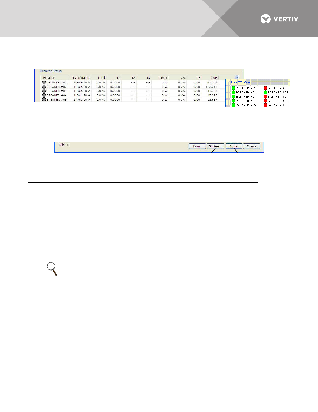
power factor (PF) and accumulated kilowatt hours (kWh). The example below right shows the
Icon View of
Breaker Status
Table View of Breaker Status
Subfeeds/Breakers
Button
Icons/Table
Button
icon format.
5.4.6 Mode Buttons
Mode buttons at the bottom of the window allow users to toggle the Breaker Status display
between subfeed and branch breakers (Subfeeds/Breakers) or between icon and table formats
(Icons/Table) and access the Event Log (Events).
Table 9 Monitor mode buttons
Button Function
Subfeeds/
Breakers
Icons/ Table
Events Displays the Event Log dialog box.
Toggles between component types in the Breaker Status area: subfeed breakers and
branch breakers.
The button label changes when the display is changed.
Toggles between formats for displaying data in the Breaker Status area: icon view and
table view.
The button label changes when the display is changed.
5.5 Using the Configuration Tool
The Configuration tool allows users to set up breakers and view or change their parameters and
alarm setpoints.
NOTE
End users have the ability to modify an existing configuration file by using the Configuration
software available on the Liebert Web site, www.vertivco.com (see 5.3 - Downloading the
Software). Ensure the existing configuration file is saved locally before making any
modifications. Please contact your local Vertiv representative or call Vertiv Support at
800-543-2378 for assistance.
Vertiv™ | Liebert® LDMF™ Distribution Monitoring User Manual | 27
Page 32
5.5.1 Starting the Configuration Program
Work Offline
COM Port
Connect Locally
1
3
5
7
9
11
13
15
17
19
21
23
25
27
29
2
4
6
8
10
12
14
16
18
20
22
24
26
28
30
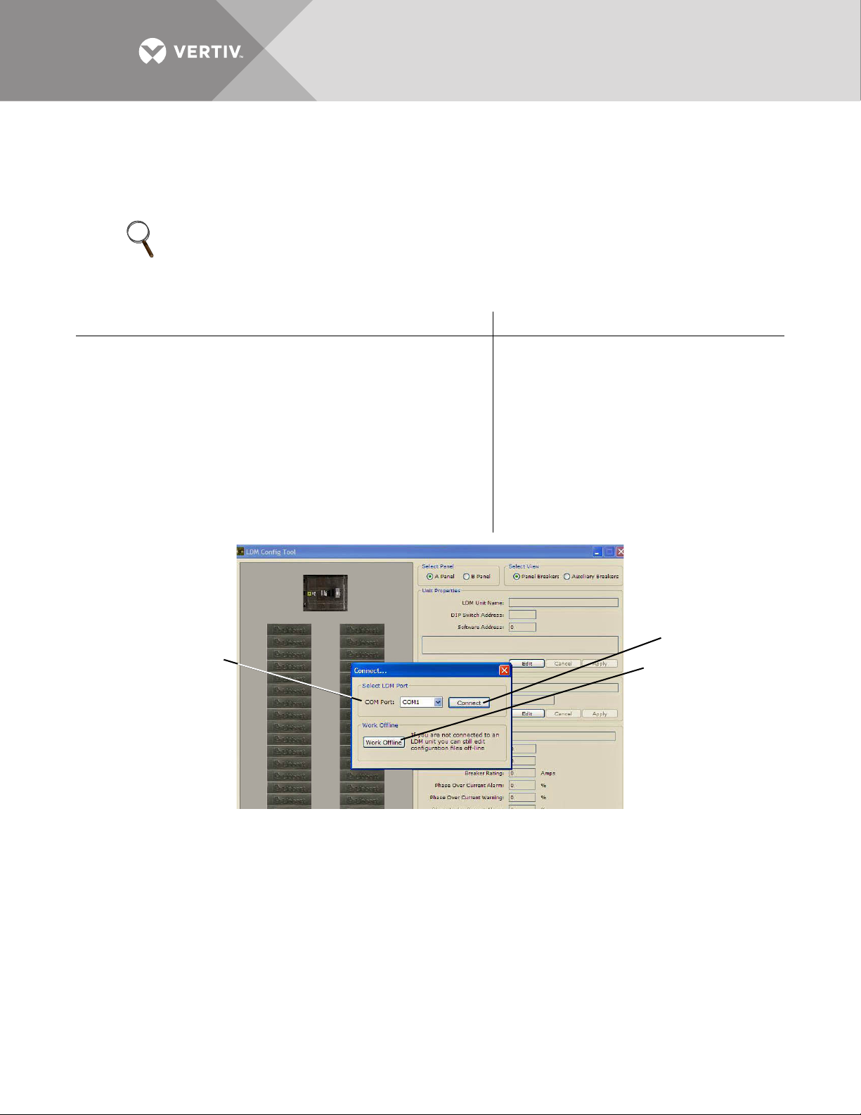
Before starting the Configuration tool, decide whether you want to connect to the Liebert LDMF
or work in offline mode.
Offline mode allows you to run the configuration tool without being connected to the equipment.
NOTE
A configuration file is required for Offline Mode. If one is not available, connect to the equipment
locally and save the configuration to disk. See 5.5.4 - Install Configuration Changes in the Unit
and 5.5.5 - Save the Configuration File to Disk.
To Connect via COM Port To Work in Offline Mode
1. If needed, download the latest version of the software
(see 5.3 - Downloading the Software).
2. Connect a PC to the Liebert LDMF via the external DB9
connection. Refer to 5.2.1 - LDMF Setup Port
Connection.
3. Run the file LDMF-Config-xx.exe (where xx is the version
number) to start the Configuration program.
4. In the Connect window, select the appropriate COM port
from the list of available ports.
5. Click Connect.
1. If needed, download the latest
version of the software (see 5.3 -
Downloading the Software).
2. Run the file LDMF-Config-xx.exe
(where xx is the version number) to
start the Configuration program.
3. In the Connect window, click the
Work Offline button, shown below.
4. When prompted for the
configuration file, navigate to the
location of the file.
5. Click Open.
Proceed to 5.5.2 - Main Configuration Window Overview to begin configuration.
When a local connection to the Liebert LDMF can be performed, load the configuration using the
instructions in 5.5.3 - Load a Configuration File from Disk.
Vertiv™ | Liebert® LDMF™ Distribution Monitoring User Manual | 28
Page 33
5.5.2 Main Configuration Window Overview
Select Panel
Select View
Unit
Properties
Mode
Buttons
Panel
Properties
Breaker
Properties
1
3
5
7
9
11
13
15
17
19
21
23
25
27
29
31
33
35
37
39
41
2
4
6
8
10
12
14
16
18
20
22
24
26
28
30
32
34
36
38
40
42
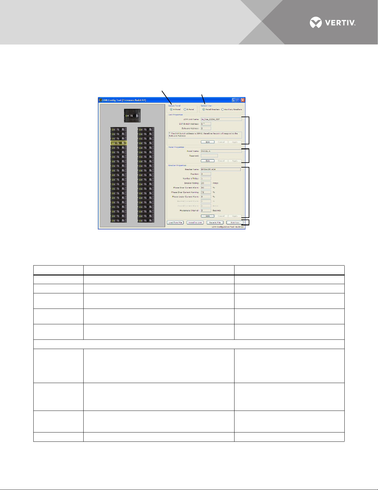
The Configuration window shows breakers graphically in the left pane and associated breaker
data at right. Selecting a breaker in the left pane changes the display of data in the right pane.
Tab le 1 0 shows the main sections of the window, along with a description and a reference to
step-by-step instructions for each.
Table 10 Overview of main Configuration window
Section Function For details, see:
Select Panel Toggles the display between Panel A and Panel B. 5.5.6 - Select Panel to View
Select View Toggles between Panel and Auxiliary Breakers. 5.5.7 - Select Breakers to View
Unit Properties
Panel
Properties
Breaker
Properties
Configuration Mode Buttons
Displays the name and communication settings of the
Liebert LDMF unit.
Displays the name of the selected panelboard; also
password setup for security purposes.
Displays breaker parameters and alarm setpoints. 5.5.10 - Edit the Breaker Properties
Uploads a saved configuration file from the PC to the
Liebert LDMF.
•Load from File
This feature may be used to install a backup copy of a
configuration file or set up a new Liebert LDMF
installation.
•Install to Unit
• Save to File
• Exit Now Closes the Configuration program. —
Vertiv™ | Liebert® LDMF™ Distribution Monitoring User Manual | 29
Uploads the current configuration from the PC to the
Liebert LDMF after making changes to the configuration.
This step is required to update the unit with the latest
changes.
Saves a copy of the configuration file to the PC.
This feature is useful when a backup copy of the
configuration file is needed.
5.5.8 - Edit the Liebert LDMF Unit
Properties
5.5.9 - Edit the Panel Properties or Set a
Password
5.5.3 - Load a Configuration File from
Disk
5.5.4 - Install Configuration Changes in
the Unit
5.5.5 - Save the Configuration File to
Disk
Page 34
5.5.3 Load a Configuration File from Disk
Load from File
Install to Unit
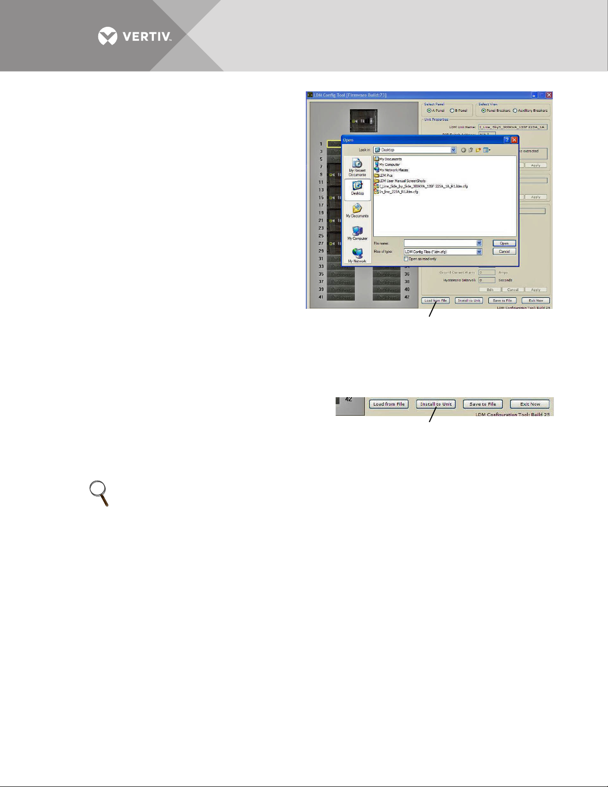
A previously saved configuration file—created
by Vertiv technical personnel or saved from a
Liebert LDMF unit—may be transferred from a
PC to the Liebert LDMF.
This feature allows for quick setup based on
another unit’s configuration or replacing a
configuration file in an existing installation.
To upload the configuration file:
• Click on the Load from File button at the bottom
of the Configuration window.
•In the Open window, navigate to the
configuration file, then click Open.
After a short delay, a confirmation message
appears. The Liebert LDMF is now updated with
all breaker and subfeed data from the
configuration file that was just loaded.
5.5.4 Install Configuration Changes in the Unit
Whenever configuration changes are made using the Configuration program, the changes must
be installed in the Liebert LDMF using this procedure.
To install changes in the unit:
1. Click on the Install to Unit button at the bottom of the
Configuration window.
2. During the upload, the circuit board will reboot and
cause a loss of communication with the monitoring
products.
Once the rebooting process is complete, the configuration is active.
NOTE
Configuration changes are not stored in the Liebert LDMF until the Install to Unit button is
clicked.
Vertiv™ | Liebert® LDMF™ Distribution Monitoring User Manual | 30
Page 35
5.5.5 Save the Configuration File to Disk
Save to File
Select Panel
Select View
Panel Breakers view Auxiliary Breakers view
1
3
5
7
9
11
13
15
17
19
21
23
25
27
29
31
33
35
37
39
41
2
4
6
8
10
12
14
16
18
20
22
24
26
28
30
32
34
36
38
40
42
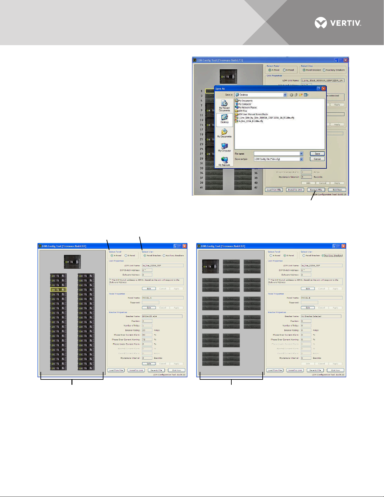
Saving the configuration file creates a copy of
the current configuration, ensuring a backup is
available in the event of file corruption or some
other problem.
• Click on the Save to File button at the bottom of
the Configuration window.
•In the Save As window:
• Specify the location where you want to save
the file in the Save In box.
• Enter a unique name in the File Name box.
•Click Save.
5.5.6 Select Panel to View
Up to two panelboards may be connected to
the Liebert LDMF (see 4.1.1 - Connecting
Panelboards A and B). Each may be viewed in
the Configuration main window.
To switch the view to a different panel:
•In the Select Panel box, click on Panel A for Panelboard A or Panel B for Panelboard B. The panel name
appears in the Panel Name box, as in the following examples.
5.5.7 Select Breakers to View
For each panelboard, two types of breakers may be configured.
To switch the view, click on a button in the Select View box (shown above):
• Panel Breakers to view circuit breakers installed in the panelboard (see example above left).
• Auxiliary Breakers to view breakers installed outside the panelboard—for example, subfeed breakers (see
example above right).
Vertiv™ | Liebert® LDMF™ Distribution Monitoring User Manual | 31
Page 36
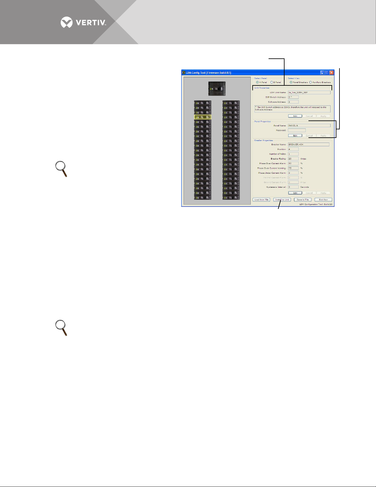
5.5.8 Edit the Liebert LDMF Unit
Unit
Properties
Panel
Properties
Install to Unit (click to save changes to Liebert LDMF)
1
3
5
7
9
11
13
15
17
19
21
23
25
27
29
31
33
35
37
39
41
2
4
6
8
10
12
14
16
18
20
22
24
26
28
30
32
34
36
38
40
42
Properties
The Unit properties box displays the name
and software address of the Liebert LDMF
unit:
• LDMF Unit Name - a name assigned to the
Liebert LDMF unit.
To make a change, click Edit and enter a name,
then click Apply.
• Software Address - the address is configured
using the communication configuration tool.
• When finished, click Install to Unit to upload
the changes to the Liebert LDMF.
NOTE
The configuration changes will not
be stored in the Liebert LDMF until
the Install to Unit button is clicked.
5.5.9 Edit the Panel Properties or Set a Password
The Panel Properties box (see image above) displays the name of the selected panelboard, as
well as a Password box for creating a password to protect against unwarranted changes to the
configuration:
• Panel Name - the default panelboard names are PANEL A and PANEL B.
To change a name, click Edit and enter a name, then click Apply.
• Password - a password required for users to make changes to the configuration file.
To create a password:
•Click in the Password box, click Edit and enter a password.
The password may be up 10 characters long and may consist of any combination of numbers, letters and
special characters. The password is not case-sensitive.
•Click Apply.
• When finished, click Install to Unit to upload the changes to the Liebert LDMF.
NOTE
The configuration changes will not be stored in the Liebert LDMF until the Install to Unit button is
clicked.
Vertiv™ | Liebert® LDMF™ Distribution Monitoring User Manual | 32
Page 37
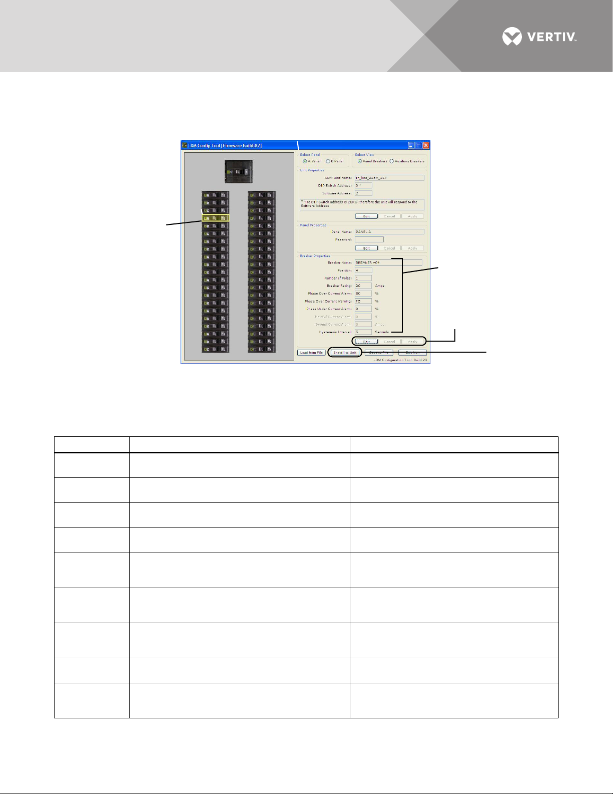
5.5.10 Edit the Breaker Properties
Breaker
Properties
Select a
Breaker
Install to Unit
(click to save
changes to
Liebert LDMF)
Edit and
Apply
buttons
1
3
5
7
9
11
13
15
17
19
21
23
25
27
29
31
33
35
37
39
41
2
4
6
8
10
12
14
16
18
20
22
24
26
28
30
32
34
36
38
40
42
The Breaker Properties box displays the breaker name, rating, breaker parameters and alarm
settings.
To view or change parameters and alarm settings of a breaker:
• Click on the breaker in the left pane. When selected, the breaker has a yellow outline.
•Refer to Table 11 to make changes:
Table 11 Edit breaker properties and description
Parameter
Breaker Name
Position
Number of
Poles
Breaker Rating
Phase
Overcurrent
Alarm
Phase
Overcurrent
Warn ing
Phase
Undercurrent
Alarm
Neutral Current
Alarm
Ground
Current
Alarm
Vertiv™ | Liebert® LDMF™ Distribution Monitoring User Manual | 33
The name of the selected breaker. The default
names are BREAKER #01, BREAKER #02, etc.
The location of the selected breaker on the
panelboard.
The number of poles selected when the breaker was
added to the panelboard.
The amperage for which the circuit breaker is rated.
The default is 20A.
Percentage of the breaker rating that triggers an
overcurrent alarm. This value must be higher than
the Phase Overcurrent Warning.
Percentage of the breaker rating that triggers an
overcurrent warning. This value must be lower than
the Phase Overcurrent Warning.
Percentage of the breaker rating that triggers an
undercurrent alarm. The default is 0 (zero), which
disables the alarm.
Percentage of the breaker that triggers a neutral
current alarm.
Amperage that triggers a ground current alarm.
Description To make a change:
• Click in the Breaker Name box, click Edit and
enter a name, then click Apply.
(Cannot be Edited)
(Cannot be Edited)
• Click in the Breaker Rating box, click Edit and
enter a value, then click Apply.
• Click in the Phase Overcurrent Alarm box,
click Edit and enter a value, then click Apply.
• Click in the Phase Overcurrent Warning box,
click Edit and enter a value, then click Apply.
• Click in the Phase Undercurrent box, click Edit
and enter a value, then click Apply.
• Click in the Neutral Current Alarm box, click
Edit and enter a value, then click Apply.
• Click in the Ground Current Alarm box, click
Edit and enter a value, then click Apply.
Page 38

NOTE
The configuration changes will not be stored in the Liebert LDMF until the Install to Unit button is
clicked.
Vertiv™ | Liebert® LDMF™ Distribution Monitoring User Manual | 34
Page 39
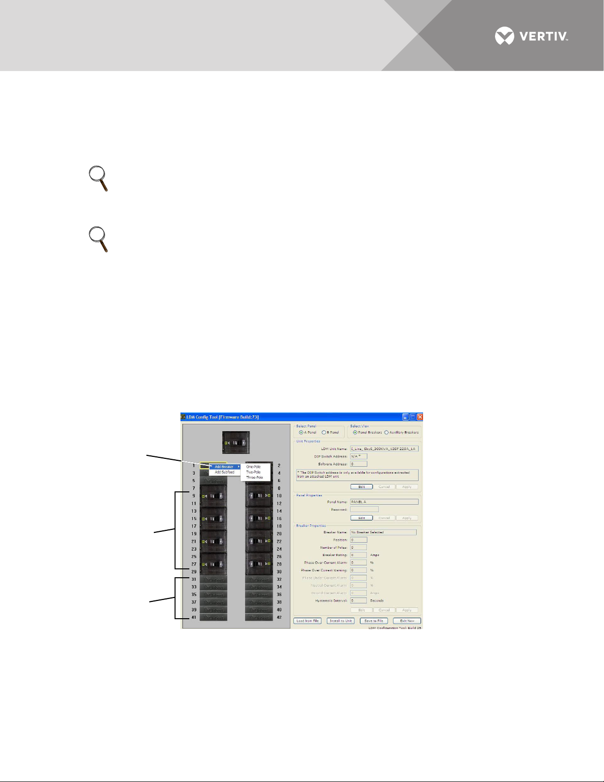
5.5.11 Add a Circuit Breaker
Assigned
Breaker Positions
Unassigned
Breaker Positions
Add Breaker
After having an electrician physically install a circuit breaker(s) in the panelboard, use the
Configuration software to add the new breaker to the configuration file.
Run the configuration program using the steps outlined in 5.5.1 - Starting the Configuration
Program. Once connected, the configuration file that is currently programmed will be displayed.
NOTE
Vertiv highly recommends saving the configuration file to the local PC as a backup before making
any changes to the configuration file. Perform the steps outlined in 5.5.5 - Save the
Configuration File to Disk before proceeding.
NOTE
Check to make sure the location for the new breaker does NOT have a breaker already assigned.
If it does, first remove that breaker assignment (see 5.5.13 - Delete a Circuit Breaker/Subfeed
Breaker), then return to this procedure.
An error message appears if you attempt to add a breaker to an assigned position.
• If NOT assigned, a breaker position is shown with a Liebert logo.
• An assigned breaker position appears as a picture of a circuit breaker.
To add a 1-, 2- or 3-pole circuit breaker:
• Run the Configuration program (see 5.5.1 - Starting the Configuration Program).
• If needed, select the panel and breaker view with the new breaker:
•In the Sel
added.
• In the Select View box, choose Panel Breakers if the new breaker is installed inside the panelboard (branch
breaker) or Auxiliary Breakers if located outside the panelboard (subfeed/output breaker).
ect Panel box, click on Panel A or Panel B depending on the panelboard where the new breaker was
• Right-click on the new breaker position in the left pane. The selected breaker has a yellow outline.
• In the pop-up menu, click on Add Breaker and then click on the type of breaker that was installed: One-Pole,
Two-Pole or Three-Pole.
•In the Breaker Properties at right, change the breaker’s name, parameters and alarm settings as needed
(see 5.5.10 - Edit the Breaker Properties).
Vertiv™ | Liebert® LDMF™ Distribution Monitoring User Manual | 35
Page 40

• When finished, click Install to Unit to upload the changes to the Liebert LDMF.
NOTE
The configuration changes will not be stored in the Liebert LDMF until the Install to Unit button is
clicked.
Vertiv™ | Liebert® LDMF™ Distribution Monitoring User Manual | 36
Page 41
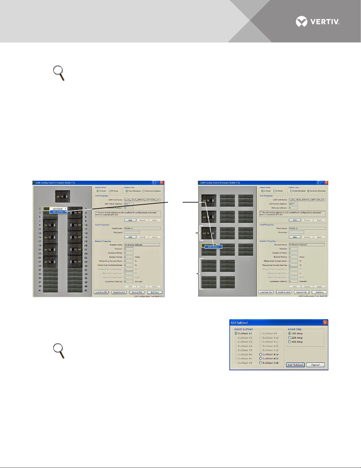
5.5.12 Adding a Subfeed Breaker
Panel Breaker View Auxiliary Breaker View
Add
Subfeed
Assigned
Breaker
Positions
Unassigned
Breaker
Positions
NOTE
Check to make sure the location for the new breaker does NOT have a breaker already assigned.
If it does, first remove that breaker assignment (see 5.5.13 - Delete a Circuit Breaker/Subfeed
Breaker), then return to this procedure.
An error message appears if you attempt to add a breaker to an already assigned position.
• If NOT assigned, a subfeed breaker position is shown with three Liebert logos.
• An assigned subfeed breaker position appears as a picture of a 3-pole breaker.
To add a 3-pole subfeed breaker circuit:
• Run the Configuration program (see 5.5.1 - Starting the Configuration Program).
• If needed, select the panel and breaker view with the new breaker:
•In the Select Panel box, click on Panel A or Panel B.
•In the Select View box, choose Panel Breakers if the new breaker is installed inside the panelboard or
Auxiliary Breakers if it is located outside the panelboard.
• Right-click on the new breaker position in the left pane. The selected breaker has a yellow outline.
• In the pop-up menu, click on Add Subfeed.
•In the Add Subfeed window:
• Click on the subfeed—for example, Subfeed #1 or Subfeed #2—
in the Select Subfeed box.
NOTE
The number of available subfeeds is determined by the
interface board selected and whether cross-configuration
is enabled.
•In the Select Size box, choose the rating of the new breaker: 100 Amp, 225 Amp or 400 Amp.
•Click on the Add Subfeed button to return to the main Configuration window.
•In the Breaker Properties box of the Configuration window, change the subfeed breaker’s name,
parameters and alarm setpoints as needed (see 5.5.10 - Edit the Breaker Properties).
Vertiv™ | Liebert® LDMF™ Distribution Monitoring User Manual | 37
Page 42
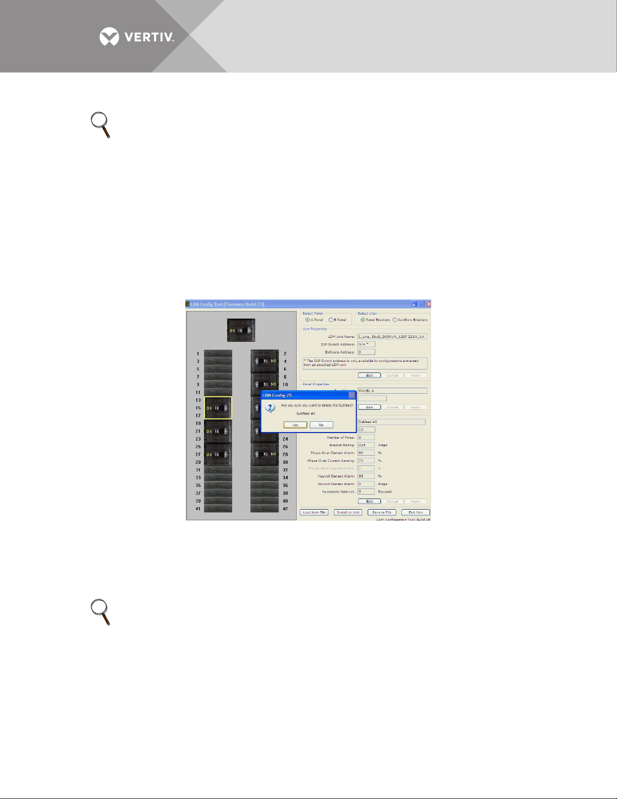
• When finished, click Install to Unit to upload the changes to the Liebert LDMF.
NOTE
The configuration changes will not be stored in the Liebert LDMF until the Install to Unit button is
clicked.
5.5.13 Delete a Circuit Breaker/Subfeed Breaker
Removing a breaker from the configuration is required after moving or removing circuit breakers
in the panelboard. This step must be performed before adding a breaker in the same position.
To delete a breaker:
• Run the Configuration program (see 5.5.1 - Starting the Configuration Program).
• If needed, select the panel and breaker view with the breaker to be deleted:
•In the Select Panel box, click on Panel A or Panel B.
•In the Select View box, choose Panel Breakers if the breaker is installed inside the panelboard or
Auxiliary Breakers if located outside the panelboard.
• Right-click on the breaker position in the left pane. The selected breaker has a yellow outline.
• In the pop-up menu, click Delete.
• A confirmation message appears, as shown above. Select Yes to delete the breaker (or No to cancel).
• Repeat as needed to delete other breakers.
• When finished, click Install to Unit to upload the changes to the Liebert LDMF.
NOTE
The configuration changes will not be stored in the Liebert LDMF until the Install to Unit button is
clicked.
Vertiv™ | Liebert® LDMF™ Distribution Monitoring User Manual | 38
Page 43
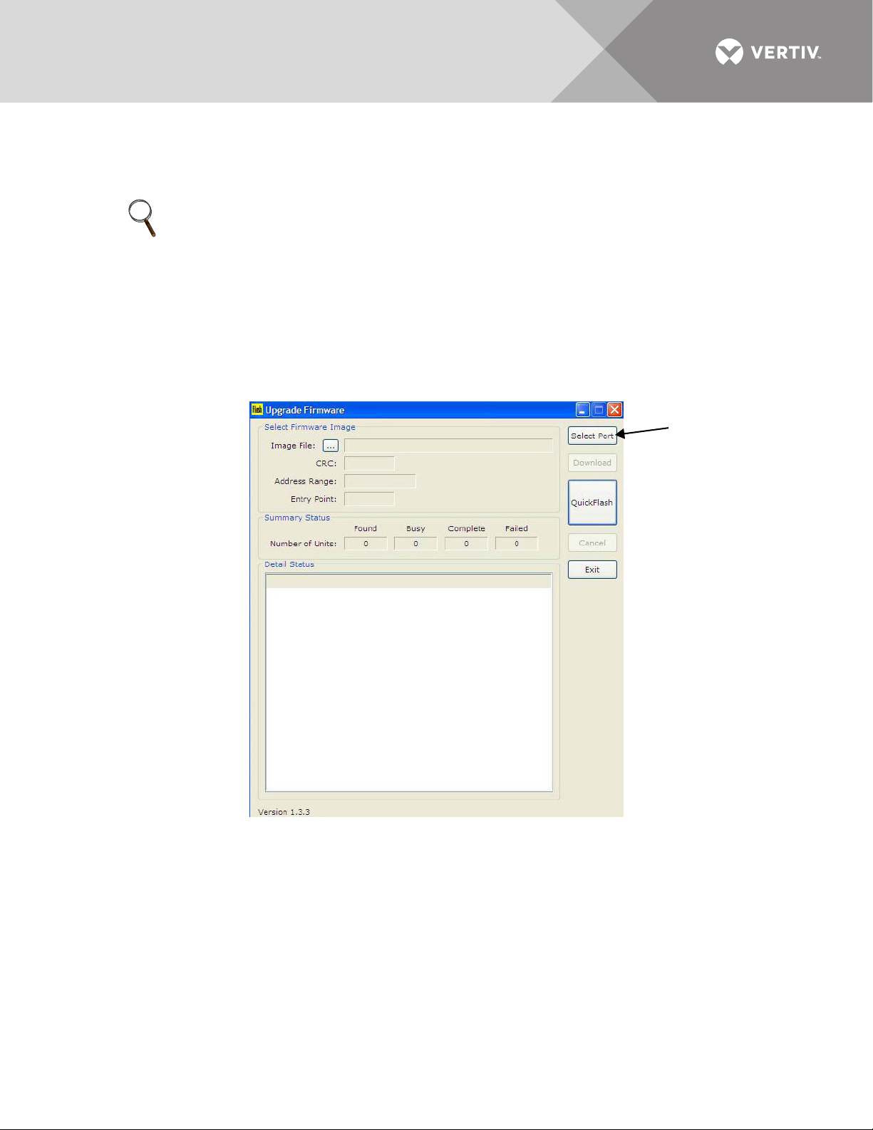
5.6 Upgrading the Firmware
Select Port
The Flash program is used to upgrade the firmware on a Liebert LDMF unit. It uses the service
terminal port to erase the old firmware, copy the new firmware and reboot the unit.
NOTE
Updating the firmware will not erase any configuration settings currently installed.
Installing a new configuration file will overwrite the Modbus address and settings.
To upgrade the firmware:
1. Make sure the Liebert LDMF unit is powered ON.
2. Connect the PC to the Liebert LDMF via the external DB9 connection. Refer to 5.2.1 - LDMF Setup Port
Connection.
3. Run the file named Flash-x.x.x.exe (where x.x.x is the version number).
4. In the Upgrade Firmware window, click the Select Port button.
Vertiv™ | Liebert® LDMF™ Distribution Monitoring User Manual | 39
Page 44
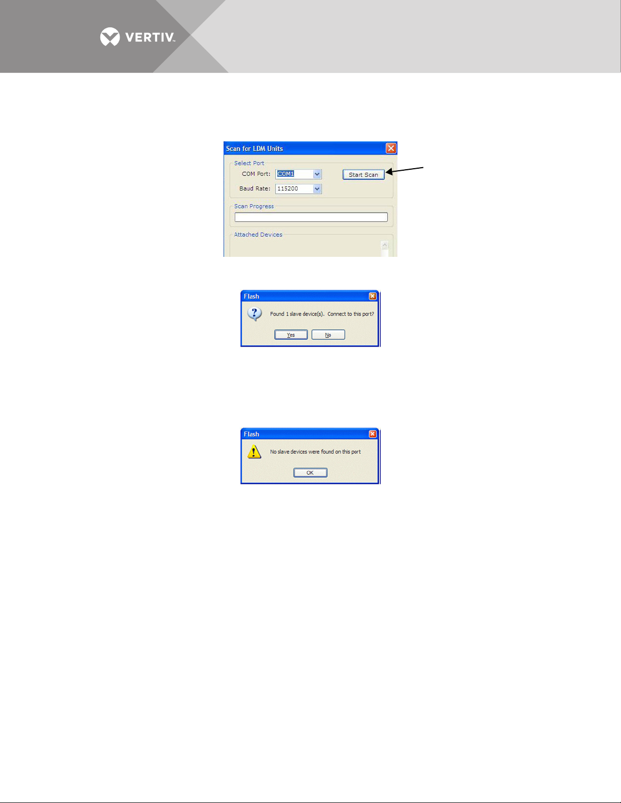
5. In the Scan for LDM Units window:
Start Scan
Button
• Select the COM port from the drop-down list—for example, COM1.
• Make sure the baud rate is 115200.
•Click the Start Scan button to check for a connection to the unit.
6. If the Liebert LDMF unit is detected, a confirmation window appears. Click Ye s to continue and proceed to
Step 7.
If the Liebert LDMF unit is NOT detected, an error message appears. Click OK to return to the Upgrade
Firmware window. Check to verify the following, then repeat Step 5:
• The correct COM Port is selected and the baud rate is 115200.
• A serial cable is properly connected to the unit (see 5.2.1 - LDMF Setup Port Connection).
• The Liebert LDMF unit is powered ON.
Vertiv™ | Liebert® LDMF™ Distribution Monitoring User Manual | 40
Page 45
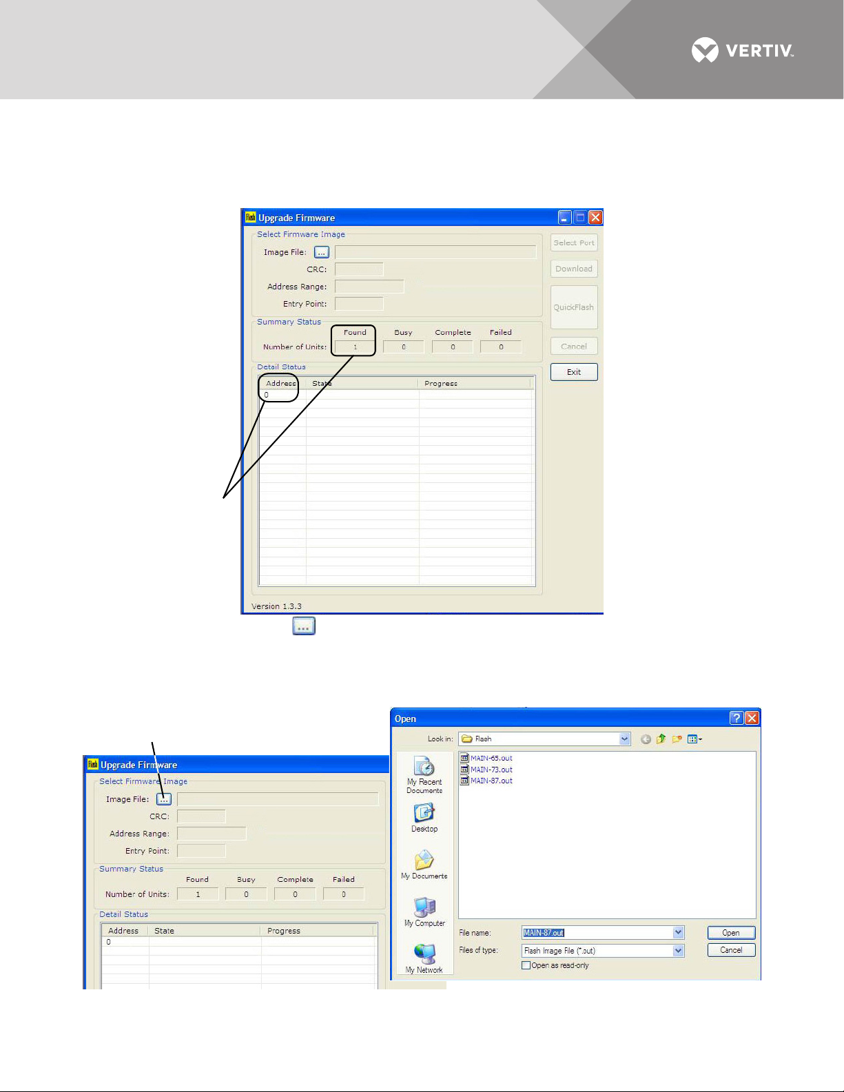
7. Verify the Upgrade Firmware window displays the following indications that the connection was
Connection
Successful
Image File button
Navigate to File
successful (shown in the example below):
•In the Summary Status box, the Number of Units should be 1 in the Found box.
•In the Detail Status box, 0 should appear in the Address column.
•The Select Port, Download, Quick Flash, and Cancel buttons are grayed-out
8. Click the Image File button (below left), and the Open window appears (below right).
• Browse to the folder where the Flash files are located—this should be the same folder where the Flash
program was installed.
• Select the file you want to download.
•Click the Open button.
Vertiv™ | Liebert® LDMF™ Distribution Monitoring User Manual | 41
Page 46
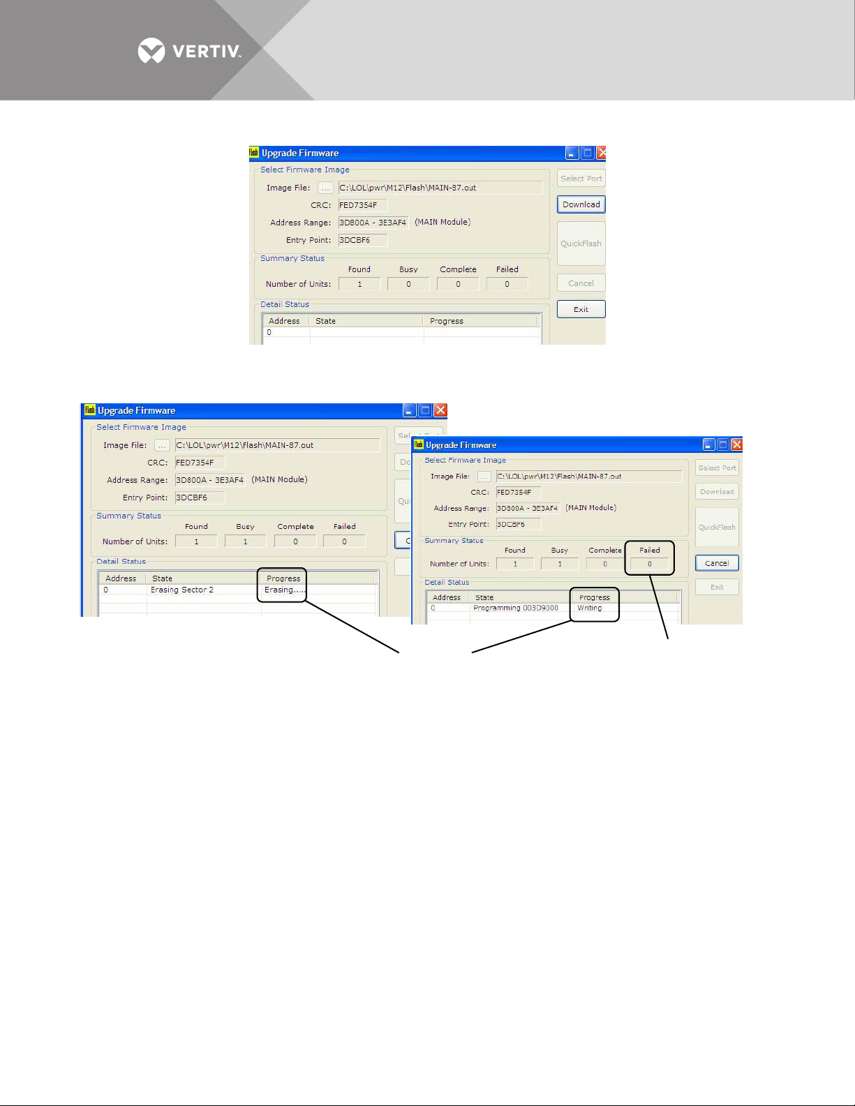
9. The Upgrade Firmware window appears. Click the Download button to continue.
Failed = 0
Progress
Column
10. Wait for the firmware upgrade to complete. The Progress column in the Detail Status Area shows the
status of the upgrade.
The program erases the old image (below left), then writes the new image (below right).
11. When the new image is loaded, the Flash program restarts the unit. Verify the following:
•In the Summary Status box, the Number of Units should be 0 under Failed (above right).
•In the Detail Status box, Running should appear in the Progress column—this indicates that the BCB
has been restarted successfully.
Vertiv™ | Liebert® LDMF™ Distribution Monitoring User Manual | 42
Page 47
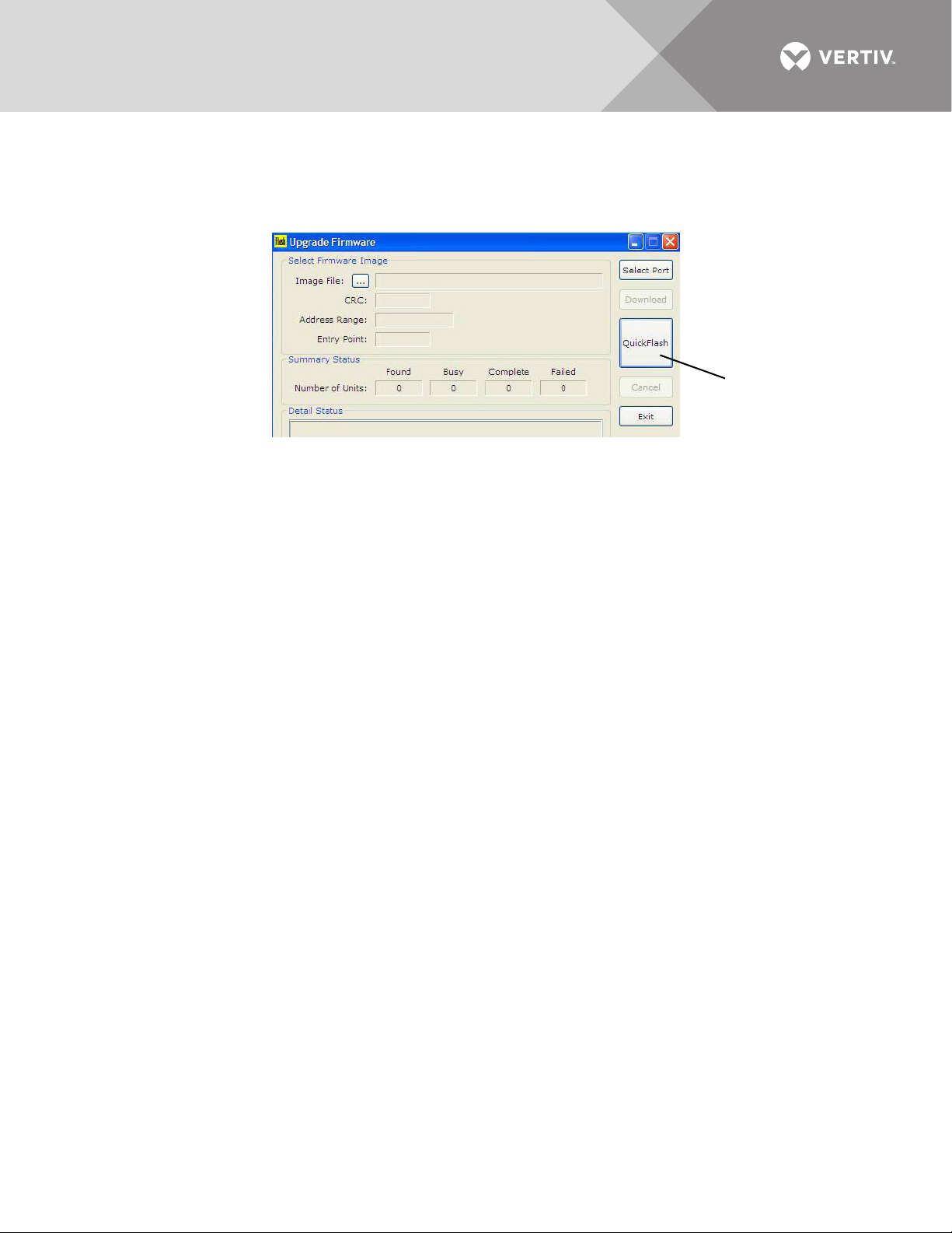
12. The Flash program has a Quick Flash feature that keeps track of where the file is stored on the local PC.
QuickFlash
Button
This feature becomes active after the initial firmware update has been completed. This makes upgrading
numerous LDMF Systems easier and less time-consuming.
Connect to each additional LDMF System, then click on the QuickFlash button to begin the update
automatically without having to specify the file location.
13. Once all LDMF Systems have been upgraded, click Exit to close the Flash program.
5.7 Display Controls (HMI)
The Liebert LDMF displays panelboard data via a local display in conjunction with the remote
capabilities. This display gives the end user a quick and easy way of viewing the panelboard
branch circuit breaker currents, panelboard voltages, alarms and status. An audible alarm is also
provided in the event that any programmed alarm threshold is exceeded.
The user interface and menu selections have been developed to make it easy to scroll through
panelboard data points with clearly labeled variable function keys. These function keys change
features depending on the menu selected to maintain a clearly visible view area.
There can be up to two HMI’s on a unit and each can display up to four panelboards.
5.7.1 Controls and Indicators
The left side of the display includes indicators and an alarm speaker:
• Power Indicator (Green LED) - illuminates when power has been applied to the Liebert power product.
• Alarm Status Indicator (Red LED - illuminates when the Liebert LDMF detects an alarm. The audible alarm
will also sound until the Silence/Reset push button is depressed. The LED will remain illuminated until the
alarm condition is cleared.
• Audible Alarm speaker (represented by the white dot) - a speaker behind the bezel will sound when the
Liebert LDMF records an alarm condition. Pressing the Silence/Reset push button mutes the audible alarm
until another alarm is generated or the alarm condition has cleared.
The middle section includes the display area and navigation keys to change the display:
• LCD viewing area - displays parametric or alarm data for selected components
• Navigation keys (soft function keys F1 through F4 and Help)—some of these keys vary in function, as
indicated in the text description above each key:
• F1 selects the next major item such as Next Main, Next Subfeed, or Next Branches.
• F2 is the Sequence key. It selects the next set of items at the current level or the next item on a list.
• F3 can select Subfeeds at the top level or can select a menu item at lower levels.
• F4 can select Branch Breakers at the top level or provide a Back function at lower levels.
Pressing the Back key (F4) navigates to the top level (Main) except from the Help screen. From the Help
screen, the Back key navigates to the previous screen.
• Pressing the Help key navigates to the Help screen.
Vertiv™ | Liebert® LDMF™ Distribution Monitoring User Manual | 43
Page 48
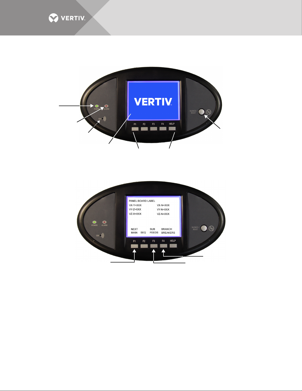
At right is the alarm Silence/Reset button:
Navigation Keys
Alarm
Silence/Reset
Push Button
Audible
Alarm
Speaker
Alarm Status
Indicator
Red
Power
Indicator
Green
LCD Viewing
Area
Next Main
Subfeeds
Branch Breakers
• Press the Silence/Reset button once and hold to silence the audible alarm.
• Press the Silence/Reset button a second time to clear the alarm and turn Off the red LED.
5.7.2 Liebert LDMF Parameter Screens
Three types of parameter screens may be selected from the Main Screen by pressing the soft
keys labeled Next Main, Subfeeds and Branch Breakers to display the applicable information.
Next Main
Press the Next Main key to display parameters for the main breaker feeding power to a
panelboard. There may or may not be a physical circuit breaker installed. The Next Main key
toggles between the two Main Panelboard breakers in a Liebert Power product with more than
one panelboard.
Subfeeds
Press the Subfeeds key to show parameters for subfeed breakers—these are usually circuit
breakers that feed remote circuits or panelboards. They may reside as separate entities within a
Liebert Power product or a special large panelboard.
Branch Breakers
Press the Branch Breakers key to view parameters for one-, two- or three-pole circuit breakers
that reside in the panelboard. The branch data resides at the lowest level except for the alarm
summary.
Vertiv™ | Liebert® LDMF™ Distribution Monitoring User Manual | 44
Page 49

5.7.3 Liebert LDMF Alarms
s
NEW ALARM (S) PRESEN T
PRESS TH E SILENCE/RESET
KEY TO RESET THE ALARM(S)
PRESS BACK T O GO TO T HE PANEL
BOARD MAIN T O REVIEW THE ALARM
TYPE(S) AND LOCATION(S)
BACK
F2 F3 F4 HELPF1
If any alarms are present when parameter screens are accessed with the Main, Subfeeds or
Branch Breakers keys, the Alarm Screen appears, as shown in the example below.
• Press F4 (Back) to view details about the alarm on the Panelboard Main screen.
• The alarm activates the Audible Alarm and the red Alarm LED.
• Press the Silence/Reset key once to silence the audible alarm.
• Press the Silence/Reset key a second time to clear the alarm. If all alarms are reset, the display returns to
the Main Alarm screen.
• If the alarm condition persists, a new alarm is generated and the sequence is repeated.
Vertiv™ | Liebert® LDMF™ Distribution Monitoring User Manual | 45
Page 50
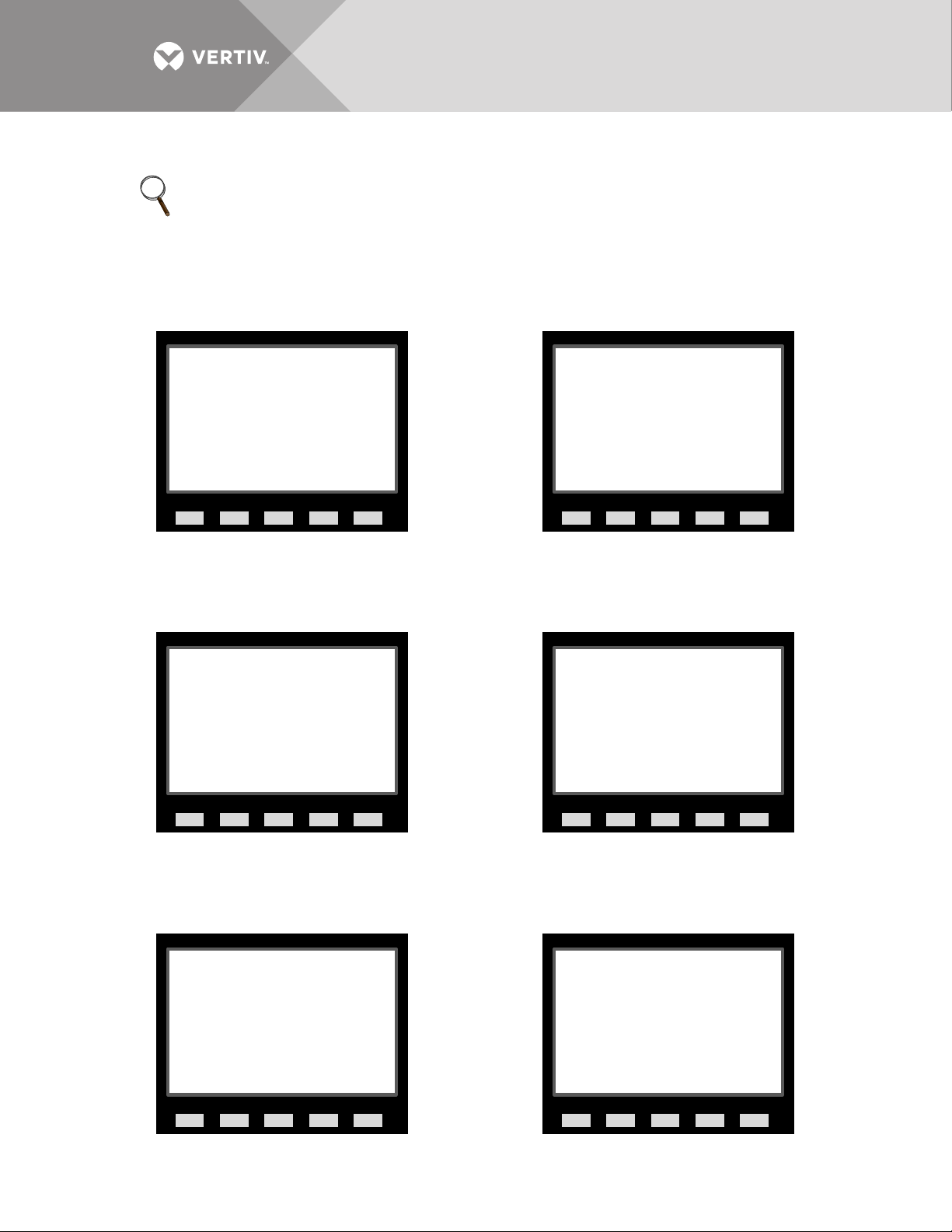
5.7.4 Liebert LDMF Screens
Panelboard Main Screen
(if no alarms are present)
Panelboard Alarms
(appears only if alarms are present)
Panelboard
Voltages
Panelboard
Currents
Panelboard
Power Values
Panelboard
Crest Factor (CF)
s
PANEL BOARD LABEL
NO ALARMS PR ESENT
NEXT SUB BRANCH
MAIN SEQ F EEDS BR KRS
F2 F3 F4 HELPF1
s
PANEL BOARD LABEL
LDM SUMM ALR M PANEL BOARD ALRM
OVER VOLT ALRM UNDER VOLT ALRM
PH OVER CURRENT NEUT OVER CURR
OVER CURR WARN GND OVER CURR ALRM
NEXT SUB BRANCH
MAIN SEQ F EEDS BR KRS
F2 F3 F4 HELPF1
s
PANEL BOARD LABEL
V X-Y = XXX V X-N = XXX
V Y-Z = XXX V Y- N = XXX
V Z-X = XXX V Z -N = XXX
NEXT SUB BRANCH
MAIN SEQ F EEDS BR EAKERS
F2 F3 F4 HELPF1
s
PANEL BOARD LABEL
IX = XXXX IN = XXXX
IY = XXXX IG = XX.X
IZ = XXXX
NEXT SUB BRANCH
MAIN SEQ F EEDS BRKRS
F2 F3 F4 HELPF1
s
PANEL BOARD LABEL
kVA = XXXX PF = 0.XX
kW = XXXX %LD = XXX
kWH = XXXXXXXX
NEXT SUB BRANCH
MAIN SEQ F EEDS BRKRS
F2 F3 F4 HELPF1
s
PANEL BOARD LABEL
IX CF = X.X
IY CF = X.X
IZ CF = XX.X
NEXT SUB BRANCH
MAIN SEQ F EEDS BRKRS
F2 F3 F4 HELPF1
NOTE
The images below are for representation of the menu items only. The actual display including the
Controls and Indicators shown in the images below may not be present.
Figure 2 Main panelboard screens—examples
Vertiv™ | Liebert® LDMF™ Distribution Monitoring User Manual | 46
Page 51
Figure 3 Subfeed screens—examples
Subfeed Main Screen
(if no alarms are present)
Subfeed Alarms
(appears only if alarms are present)
Subfeed
Crest Factor (CF) & THD
Subfeed
Current
Subfeed
Power Values
s
SUBFEED LABEL
NO ALARMS PR ESENT
NEXT
SUB FD SEQ BACK
F2 F3 F4 H ELPF1
s
SUBFEED LABEL
PH OVER CURRENT NEUT OVER CURR
OVER CURR WARN GND OVER CURR ALRM
NEXT
SUB FD SEQ BACK
F2 F3 F4 H ELPF1
s
SUBFEED LABEL
IX CF = X.X IX THD = XX.X
IY CF = X.X IY THD = XX.X
IZ CF = X.X IZ THD = XX.X
NEXT
SUB FD SEQ BACK
F2 F3 F4 H ELPF1
s
SUBFEED LABEL
IX = XXXX IN = XXXX
IY = XXXX IG = XX.X
IZ = XXXX
NEXT
SUB FD SEQ BACK
F2 F3 F4 H ELPF1
s
SUBFEED LABEL
kVA = XXXX PF = 0.XX
kW = XXXX %LD = XXX
kWH = XXXXXXXX
NEXT
SUB FD SEQ BACK
F2 F3 F4 H ELPF1
Vertiv™ | Liebert® LDMF™ Distribution Monitoring User Manual | 47
Page 52
Figure 4 Branch breaker screens—examples
Branch Breaker Main Screen
(if no alarms are present)
Branch
Breakers
Branch
Alarms
Branch
Current
Branch
Power Values
s
PANEL BOARD LABEL
BRANC H LABEL
NO ALARMS PR ESENT
(or BRANCH AL ARMS PRESENT)
SEQ BACK
F2 F3 F4 H ELPF1
s
PANEL BOARD LABEL
BRANCH LABEL ONE
BRANC H LABEL T WO
BRANCH LABEL THREE
BRANCH LABEL FOUR
BRANC H LABEL F IVE
BRANC H LABEL S IX
BRANCH LABEL SEVEN
NEXT NEXT
GROUP BRANCH SELECT BACK
F2 F3 F4 H ELPF1
s
PANEL BOARD LABEL
BRANC H LABEL
NO ALARM S PRESENT or
OVER CURR ALRM OVER CURR WARN
UNDER CURR WARN
SEQ BACK
F2 F3 F4 H ELPF1
s
PANEL BOARD LABEL
BRANC H LABEL
CURRENT 1 = xxx.x
CURRENT 2 = xxx.x
CURRENT 3 = xxx.x
%LD = XXX
SEQ BACK
F2 F3 F4 H ELPF1
s
PANEL BOARD LABEL
BRANC H LABEL
kW = XXXX PF = 0.XX
kWH = XXXXXXXX (8 digit s)
SEQ BAC K
F2 F3 F4 H ELPF1
Vertiv™ | Liebert® LDMF™ Distribution Monitoring User Manual | 48
Page 53
6.0 SPECIFICATIONS
ELECTRICAL
Voltag e 120 - 240 VAC (-1 3% to +6%)
Frequency 50 and 60Hz
Current Transformers Rating
(Secondary Winding)
BSM Current 0.5A to 120A
CT Accuracy
Minimum Current 200mA
ENVIRONMENTAL
Humidity 0-95%
Temperature (Non-Operating) -68°F to 158°F (-20°C to 70°C)
Temperature (Operating) 32°F to 104°F (0°C to 40°C)
1A for Branch Circuits and Subfeeds
1A for Panelboard Main Breaker
5% for 0.5-2A
1% for 2 - 100A
5% for 100-120A
Vertiv™ | Liebert® LDMF™ Distribution Monitoring User Manual | 49
Page 54

7.0 TROUBLESHOOTING / FREQUENTLY ASKED QUESTIONS
1. How do I obtain the software necessary to monitor and configure the Liebert LDMF?
• The software package is available from the Liebert Web site, www.vertivco.com. Under Service and
Support, choose Software Downloads.
• Click on the link for the LDMF - mm/yyyy Toolkit:
where mm/yyyy is the month and year of the update—for example, 08/2016 or 11/2016
Note: There are two versions of Liebert Distribution Monitoring software.
Be sure to select the LDMF version, which is for units with a setup port labeled LDMF Setup.
Do NOT choose the Liebert Distribution Monitoring (LDM) Tool Kit. (The LDM Tool Kit is used
on units with a setup port labeled LDM Setup.)
• Save the file to a desktop or laptop computer (PC) and extract the contents.
NOTE
The software may be updated and changed without any notification. Check the Web site
regularly to ensure the software is up-to-date.
2. What is contained in the downloaded software package?
• The flash program with a walk-through instruction
• The configuration program
•The monitor program
3. What should I do if the BMS is reporting an overcurrent alarm?
• Verify the circuit is not actually overloaded.
• Using the Configuration program, verify that alarm setpoints and the CT ratio are correct.
• If settings are correct, verify that the BMS is operating correctly.
• If the issue still exists, contact Vertiv Support at 800-543-2378 for assistance.
4. I get an error message “Incorrect Schema Version” when I try to run the Monitor tool or Configuration tool.
What should I do?
• Ensure that only one program—either Monitor or Configuration—is running at a time. You can’t run
both programs at the same time.
• Contact Vertiv Support to ensure correct tool for the firmware.
• Verify the PC is connected to the LDMF Setup port and the communication cable (F-F null modem DB9)
is fully seated (see 5.2.1 - LDMF Setup Port Connection).
• Verify the Liebert LDMF unit has power (green LEDs on the BCB will be flashing).
5. How can I make a backup copy of the configuration file?
• Connect to the external LDMF Setup port (see 5.2.1 - LDMF Setup Port Connection).
• Run the configuration program (see 5.5.1 - Starting the Configuration Program).
• At the bottom of the Configuration window, select Save to File. Navigate to a location on your PC to
store the file (see 5.5.5 - Save the Configuration File to Disk).
Vertiv™ | Liebert® LDMF™ Distribution Monitoring User Manual | 50
Page 55

Page 56

VertivCo.com | Vertiv Headquarters, 1050 Dearborn Drive, Columbus, OH, 43085, USA
© 2018 Vertiv Co. All rights reserved. Vertiv and the Vertiv logo are trademarks or registered trademarks of Vertiv Co. All other names and logos referred to
are trade names, trademarks or registered trademarks of their respective owners. While every precaution has been taken to ensure accuracy and
completeness herein, Vertiv Co. assumes no responsibility, and disclaims all liability, for damages resulting from use of this information or for any errors or
omissions. Specifications are subject to change without notice.
SL-20200_REV8_8-18
 Loading...