

Vertiv Liebert ITA2-08KRT208, Liebert ITA2-08KRT208C, Liebert ITA2-10KRT208C, Liebert ITA2-10KRT208 User Manual

Liebert®
ITA2™ 8-10kVA, 60Hz, 208/220V Three-Phase UPS
User Manual

The information contained in this document is subject to change
without notice and may not be suitable for all applications. While
every precaution has been taken to ensure the accuracy and
completeness of this document, Vertiv assumes no responsibility
and disclaims all liability for damages resulting from use of this
information or for any errors or omissions. Refer to other local
practices or building codes as applicable for the correct methods,
tools, and materials to be used in performing procedures not
specifically described in this document.
The products covered by this instruction manual are manufactured
and/or sold by Vertiv This document is the property of Vertiv and
contains confidential and proprietary information owned by Vertiv.
Any copying, use or disclosure of it without the written permission of
Vertiv is strictly prohibited.
Names of companies and products are trademarks or registered
trademarks of the respective companies. Any questions regarding
usage of trademark names should be directed to the original
manufacturer.
Technical Support Site
If you encounter any installation or operational issues with your product, check the pertinent
section of this manual to see if the issue can be resolved by following outlined procedures.
Visit https://www.VertivCo.com/en-us/support/ for additional assistance.

TABLE OF CONTENTS
CONTACTING VERTIV™ FOR SUPPORT . . . . . . . . . . . . . . . . . . . . . . INSIDE FRONT COVER
IMPORTANT SAFETY INSTRUCTIONS . . . . . . . . . . . . . . . . . . . . . . . . . . . . . . . . . . . . . . 1
SAVE THESE INSTRUCTIONS . . . . . . . . . . . . . . . . . . . . . . . . . . . . . . . . . . . . . . . . . . . . . . . 1
1.0 INTRODUCTION. . . . . . . . . . . . . . . . . . . . . . . . . . . . . . . . . . . . . . . . . . . . . . . . . . . . . . . 3
1.1 Features . . . . . . . . . . . . . . . . . . . . . . . . . . . . . . . . . . . . . . . . . . . . . . . . . . . . . . . . . . . . . . . . . . . . . . . . . . . . . . . . . 3
1.2 Model Configurations. . . . . . . . . . . . . . . . . . . . . . . . . . . . . . . . . . . . . . . . . . . . . . . . . . . . . . . . . . . . . . . . . . . . 3
1.3 Appearance and Components . . . . . . . . . . . . . . . . . . . . . . . . . . . . . . . . . . . . . . . . . . . . . . . . . . . . . . . . . . . 4
1.3.1 Components—Front Panel . . . . . . . . . . . . . . . . . . . . . . . . . . . . . . . . . . . . . . . . . . . . . . . . . . . . . . . . . . . . . . . 4
1.3.2 Components—Rear Panel . . . . . . . . . . . . . . . . . . . . . . . . . . . . . . . . . . . . . . . . . . . . . . . . . . . . . . . . . . . . . . . . 4
1.4 Major Components . . . . . . . . . . . . . . . . . . . . . . . . . . . . . . . . . . . . . . . . . . . . . . . . . . . . . . . . . . . . . . . . . . . . . . 5
1.4.1 Transient Voltage Surge Suppression (TVSS) and EMI/RFI Filters . . . . . . . . . . . . . . . . . . . . . . . 5
1.4.2 Rectifier/Power Factor Correction (PFC) Circuit . . . . . . . . . . . . . . . . . . . . . . . . . . . . . . . . . . . . . . . . . 5
1.4.3 Inverter . . . . . . . . . . . . . . . . . . . . . . . . . . . . . . . . . . . . . . . . . . . . . . . . . . . . . . . . . . . . . . . . . . . . . . . . . . . . . . . . . . . 5
1.4.4 DC-DC Charger. . . . . . . . . . . . . . . . . . . . . . . . . . . . . . . . . . . . . . . . . . . . . . . . . . . . . . . . . . . . . . . . . . . . . . . . . . . 5
1.4.5 Static Bypass Switch . . . . . . . . . . . . . . . . . . . . . . . . . . . . . . . . . . . . . . . . . . . . . . . . . . . . . . . . . . . . . . . . . . . . . 5
1.4.6 Battery Cabinets . . . . . . . . . . . . . . . . . . . . . . . . . . . . . . . . . . . . . . . . . . . . . . . . . . . . . . . . . . . . . . . . . . . . . . . . . 6
1.5 UPS State and Operation Mode. . . . . . . . . . . . . . . . . . . . . . . . . . . . . . . . . . . . . . . . . . . . . . . . . . . . . . . . . . 6
1.5.1 Normal Mode . . . . . . . . . . . . . . . . . . . . . . . . . . . . . . . . . . . . . . . . . . . . . . . . . . . . . . . . . . . . . . . . . . . . . . . . . . . . . 6
1.5.2 Bypass Mode . . . . . . . . . . . . . . . . . . . . . . . . . . . . . . . . . . . . . . . . . . . . . . . . . . . . . . . . . . . . . . . . . . . . . . . . . . . . . 7
1.5.3 Battery Mode . . . . . . . . . . . . . . . . . . . . . . . . . . . . . . . . . . . . . . . . . . . . . . . . . . . . . . . . . . . . . . . . . . . . . . . . . . . . . 7
1.5.4 Auto Restart Mode . . . . . . . . . . . . . . . . . . . . . . . . . . . . . . . . . . . . . . . . . . . . . . . . . . . . . . . . . . . . . . . . . . . . . . . 8
1.5.5 Eco Mode—Single UPS. . . . . . . . . . . . . . . . . . . . . . . . . . . . . . . . . . . . . . . . . . . . . . . . . . . . . . . . . . . . . . . . . . . 8
1.5.6 Fault State. . . . . . . . . . . . . . . . . . . . . . . . . . . . . . . . . . . . . . . . . . . . . . . . . . . . . . . . . . . . . . . . . . . . . . . . . . . . . . . . 8
1.5.7 Maintenance Bypass Mode. . . . . . . . . . . . . . . . . . . . . . . . . . . . . . . . . . . . . . . . . . . . . . . . . . . . . . . . . . . . . . . 9
2.0 SINGLE UPS INSTALLATION AND COMMISSIONING . . . . . . . . . . . . . . . . . . 10
2.1 Unpacking and Inspection . . . . . . . . . . . . . . . . . . . . . . . . . . . . . . . . . . . . . . . . . . . . . . . . . . . . . . . . . . . . . . 10
2.2 Moving the UPS. . . . . . . . . . . . . . . . . . . . . . . . . . . . . . . . . . . . . . . . . . . . . . . . . . . . . . . . . . . . . . . . . . . . . . . . . 11
2.3 Installation Preparation . . . . . . . . . . . . . . . . . . . . . . . . . . . . . . . . . . . . . . . . . . . . . . . . . . . . . . . . . . . . . . . . . 12
2.3.1 Location . . . . . . . . . . . . . . . . . . . . . . . . . . . . . . . . . . . . . . . . . . . . . . . . . . . . . . . . . . . . . . . . . . . . . . . . . . . . . . . . . 12
2.3.2 Environmental Requirements . . . . . . . . . . . . . . . . . . . . . . . . . . . . . . . . . . . . . . . . . . . . . . . . . . . . . . . . . . . 12
2.3.3 Installation Tools . . . . . . . . . . . . . . . . . . . . . . . . . . . . . . . . . . . . . . . . . . . . . . . . . . . . . . . . . . . . . . . . . . . . . . . . 13
2.4 External Protective Devices . . . . . . . . . . . . . . . . . . . . . . . . . . . . . . . . . . . . . . . . . . . . . . . . . . . . . . . . . . . . 13
2.4.1 Rectifier and Bypass Input . . . . . . . . . . . . . . . . . . . . . . . . . . . . . . . . . . . . . . . . . . . . . . . . . . . . . . . . . . . . . . 13
2.4.2 Battery Input . . . . . . . . . . . . . . . . . . . . . . . . . . . . . . . . . . . . . . . . . . . . . . . . . . . . . . . . . . . . . . . . . . . . . . . . . . . . 14
2.4.3 UPS Output. . . . . . . . . . . . . . . . . . . . . . . . . . . . . . . . . . . . . . . . . . . . . . . . . . . . . . . . . . . . . . . . . . . . . . . . . . . . . . 14
2.5 Mechanical Installation . . . . . . . . . . . . . . . . . . . . . . . . . . . . . . . . . . . . . . . . . . . . . . . . . . . . . . . . . . . . . . . . . 14
2.5.1 Tower Installation . . . . . . . . . . . . . . . . . . . . . . . . . . . . . . . . . . . . . . . . . . . . . . . . . . . . . . . . . . . . . . . . . . . . . . . 14
2.5.2 Rack Installation. . . . . . . . . . . . . . . . . . . . . . . . . . . . . . . . . . . . . . . . . . . . . . . . . . . . . . . . . . . . . . . . . . . . . . . . . 15
2.6 Connecting Power Cables . . . . . . . . . . . . . . . . . . . . . . . . . . . . . . . . . . . . . . . . . . . . . . . . . . . . . . . . . . . . . . 18
2.6.1 Connecting I/O Cables . . . . . . . . . . . . . . . . . . . . . . . . . . . . . . . . . . . . . . . . . . . . . . . . . . . . . . . . . . . . . . . . . . 18
2.6.2 Single-Input Configuration . . . . . . . . . . . . . . . . . . . . . . . . . . . . . . . . . . . . . . . . . . . . . . . . . . . . . . . . . . . . . . 19
2.6.3 Dual-Input Configuration . . . . . . . . . . . . . . . . . . . . . . . . . . . . . . . . . . . . . . . . . . . . . . . . . . . . . . . . . . . . . . . .20
2.6.4 Connecting Battery Cables. . . . . . . . . . . . . . . . . . . . . . . . . . . . . . . . . . . . . . . . . . . . . . . . . . . . . . . . . . . . . . 22
Vertiv | Liebert® ITA2™ User Manual | i

3.0 OPERATION AND DISPLAY PANEL . . . . . . . . . . . . . . . . . . . . . . . . . . . . . . . . . . .25
3.1 LED Indicators . . . . . . . . . . . . . . . . . . . . . . . . . . . . . . . . . . . . . . . . . . . . . . . . . . . . . . . . . . . . . . . . . . . . . . . . . .26
3.1.1 Audible Alarm (Buzzer). . . . . . . . . . . . . . . . . . . . . . . . . . . . . . . . . . . . . . . . . . . . . . . . . . . . . . . . . . . . . . . . . . 26
3.1.2 LCD And Function Keys . . . . . . . . . . . . . . . . . . . . . . . . . . . . . . . . . . . . . . . . . . . . . . . . . . . . . . . . . . . . . . . . . 26
3.2 LCD Menu Structure . . . . . . . . . . . . . . . . . . . . . . . . . . . . . . . . . . . . . . . . . . . . . . . . . . . . . . . . . . . . . . . . . . . .27
3.3 LCD Screen Types . . . . . . . . . . . . . . . . . . . . . . . . . . . . . . . . . . . . . . . . . . . . . . . . . . . . . . . . . . . . . . . . . . . . . .28
3.3.1 Start Screen . . . . . . . . . . . . . . . . . . . . . . . . . . . . . . . . . . . . . . . . . . . . . . . . . . . . . . . . . . . . . . . . . . . . . . . . . . . . . 28
3.3.2 UPS Mimic Screen . . . . . . . . . . . . . . . . . . . . . . . . . . . . . . . . . . . . . . . . . . . . . . . . . . . . . . . . . . . . . . . . . . . . . . . 28
3.3.3 Main Menu Screen. . . . . . . . . . . . . . . . . . . . . . . . . . . . . . . . . . . . . . . . . . . . . . . . . . . . . . . . . . . . . . . . . . . . . . .29
3.3.4 Submenu Screen . . . . . . . . . . . . . . . . . . . . . . . . . . . . . . . . . . . . . . . . . . . . . . . . . . . . . . . . . . . . . . . . . . . . . . . . 29
3.4 Language Selection. . . . . . . . . . . . . . . . . . . . . . . . . . . . . . . . . . . . . . . . . . . . . . . . . . . . . . . . . . . . . . . . . . . . .35
3.5 Changing Current Date And Time . . . . . . . . . . . . . . . . . . . . . . . . . . . . . . . . . . . . . . . . . . . . . . . . . . . . . .35
3.6 Setting the Password . . . . . . . . . . . . . . . . . . . . . . . . . . . . . . . . . . . . . . . . . . . . . . . . . . . . . . . . . . . . . . . . . . .36
3.6.1 LCD Parameter Settings. . . . . . . . . . . . . . . . . . . . . . . . . . . . . . . . . . . . . . . . . . . . . . . . . . . . . . . . . . . . . . . . . 38
3.6.2 Default Screen. . . . . . . . . . . . . . . . . . . . . . . . . . . . . . . . . . . . . . . . . . . . . . . . . . . . . . . . . . . . . . . . . . . . . . . . . . 40
4.0 OPERATING INSTRUCTIONS . . . . . . . . . . . . . . . . . . . . . . . . . . . . . . . . . . . . . . . . . 41
4.1 UPS Startup. . . . . . . . . . . . . . . . . . . . . . . . . . . . . . . . . . . . . . . . . . . . . . . . . . . . . . . . . . . . . . . . . . . . . . . . . . . . . 41
4.1.1 Initial Startup Guide . . . . . . . . . . . . . . . . . . . . . . . . . . . . . . . . . . . . . . . . . . . . . . . . . . . . . . . . . . . . . . . . . . . . . 41
4.2 Transfer Between Operation Modes . . . . . . . . . . . . . . . . . . . . . . . . . . . . . . . . . . . . . . . . . . . . . . . . . . . .43
4.2.1 Transfer from Inverter Mode to Bypass Mode . . . . . . . . . . . . . . . . . . . . . . . . . . . . . . . . . . . . . . . . . . . 43
4.2.2 Transfer From Bypass Mode to Inverter Mode . . . . . . . . . . . . . . . . . . . . . . . . . . . . . . . . . . . . . . . . . .44
4.3 REPO. . . . . . . . . . . . . . . . . . . . . . . . . . . . . . . . . . . . . . . . . . . . . . . . . . . . . . . . . . . . . . . . . . . . . . . . . . . . . . . . . . . .45
5.0 COMMUNICATION . . . . . . . . . . . . . . . . . . . . . . . . . . . . . . . . . . . . . . . . . . . . . . . . . . 46
5.1 Liebert IntelliSlot Port . . . . . . . . . . . . . . . . . . . . . . . . . . . . . . . . . . . . . . . . . . . . . . . . . . . . . . . . . . . . . . . . . 46
5.1.1 Liebert IS-UNITY-DP Card. . . . . . . . . . . . . . . . . . . . . . . . . . . . . . . . . . . . . . . . . . . . . . . . . . . . . . . . . . . . . . .46
5.1.2 Liebert IS-Relay Card. . . . . . . . . . . . . . . . . . . . . . . . . . . . . . . . . . . . . . . . . . . . . . . . . . . . . . . . . . . . . . . . . . . .46
5.2 Connection Cables for Dry Contact Port. . . . . . . . . . . . . . . . . . . . . . . . . . . . . . . . . . . . . . . . . . . . . . . .47
5.3 Connecting USB Communication Cables . . . . . . . . . . . . . . . . . . . . . . . . . . . . . . . . . . . . . . . . . . . . . . 48
5.4 Connecting Serial Port Communication Cables. . . . . . . . . . . . . . . . . . . . . . . . . . . . . . . . . . . . . . . . 48
5.5 Connecting MultiFunction Port . . . . . . . . . . . . . . . . . . . . . . . . . . . . . . . . . . . . . . . . . . . . . . . . . . . . . . . . 49
6.0 MAINTENANCE . . . . . . . . . . . . . . . . . . . . . . . . . . . . . . . . . . . . . . . . . . . . . . . . . . . . . 50
6.1 Battery Maintenance . . . . . . . . . . . . . . . . . . . . . . . . . . . . . . . . . . . . . . . . . . . . . . . . . . . . . . . . . . . . . . . . . . 50
6.2 Cleaning the UPS . . . . . . . . . . . . . . . . . . . . . . . . . . . . . . . . . . . . . . . . . . . . . . . . . . . . . . . . . . . . . . . . . . . . . . 50
7.0 OPTIONS. . . . . . . . . . . . . . . . . . . . . . . . . . . . . . . . . . . . . . . . . . . . . . . . . . . . . . . . . . . . . 51
7.1 Battery Cabinet Appearance . . . . . . . . . . . . . . . . . . . . . . . . . . . . . . . . . . . . . . . . . . . . . . . . . . . . . . . . . . . 51
7.1.1 Standard Battery Cabinet Backup Time with a Single UPS. . . . . . . . . . . . . . . . . . . . . . . . . . . . . . 52
8.0 SPECIFICATIONS. . . . . . . . . . . . . . . . . . . . . . . . . . . . . . . . . . . . . . . . . . . . . . . . . . . . .53
APPENDIX A - UPS PROMPTS AND ALARMS . . . . . . . . . . . . . . . . . . . . . . . . . . . . . A54
A.1 Prompt Window . . . . . . . . . . . . . . . . . . . . . . . . . . . . . . . . . . . . . . . . . . . . . . . . . . . . . . . . . . . . . . . . . . . . . . . . .54
A.2 UPS Alarm Message List. . . . . . . . . . . . . . . . . . . . . . . . . . . . . . . . . . . . . . . . . . . . . . . . . . . . . . . . . . . . . . . .54
Vertiv | Liebert® ITA2™ User Manual | ii

FIGURES
Figure 1 UPS front panel . . . . . . . . . . . . . . . . . . . . . . . . . . . . . . . . . . . . . . . . . . . . . . . . . . . . . . . . . . . . . . . . . . . . . . 4
Figure 2 UPS rear panel . . . . . . . . . . . . . . . . . . . . . . . . . . . . . . . . . . . . . . . . . . . . . . . . . . . . . . . . . . . . . . . . . . . . . . . 4
Figure 3 UPS operating principle . . . . . . . . . . . . . . . . . . . . . . . . . . . . . . . . . . . . . . . . . . . . . . . . . . . . . . . . . . . . . . 5
Figure 4 Normal Mode . . . . . . . . . . . . . . . . . . . . . . . . . . . . . . . . . . . . . . . . . . . . . . . . . . . . . . . . . . . . . . . . . . . . . . . . . 6
Figure 5 Bypass Mode . . . . . . . . . . . . . . . . . . . . . . . . . . . . . . . . . . . . . . . . . . . . . . . . . . . . . . . . . . . . . . . . . . . . . . . . . 7
Figure 6 Battery Mode. . . . . . . . . . . . . . . . . . . . . . . . . . . . . . . . . . . . . . . . . . . . . . . . . . . . . . . . . . . . . . . . . . . . . . . . . 7
Figure 7 Maintenance Bypass Mode. . . . . . . . . . . . . . . . . . . . . . . . . . . . . . . . . . . . . . . . . . . . . . . . . . . . . . . . . . . 9
Figure 8 Unpacking cardboard box. . . . . . . . . . . . . . . . . . . . . . . . . . . . . . . . . . . . . . . . . . . . . . . . . . . . . . . . . . . 11
Figure 9 Installation clearances . . . . . . . . . . . . . . . . . . . . . . . . . . . . . . . . . . . . . . . . . . . . . . . . . . . . . . . . . . . . . . 12
Figure 10 RCCB symbols. . . . . . . . . . . . . . . . . . . . . . . . . . . . . . . . . . . . . . . . . . . . . . . . . . . . . . . . . . . . . . . . . . . . . . . 14
Figure 11 Connecting the support base with support base extension. . . . . . . . . . . . . . . . . . . . . . . . . 14
Figure 12 Assemble the support base for UPS and battery cabinets . . . . . . . . . . . . . . . . . . . . . . . . . . 15
Figure 13 UPS and battery cabinet installation complete. . . . . . . . . . . . . . . . . . . . . . . . . . . . . . . . . . . . . . 15
Figure 14 Installing brackets. . . . . . . . . . . . . . . . . . . . . . . . . . . . . . . . . . . . . . . . . . . . . . . . . . . . . . . . . . . . . . . . . . . 15
Figure 15 Guide rail and screw. . . . . . . . . . . . . . . . . . . . . . . . . . . . . . . . . . . . . . . . . . . . . . . . . . . . . . . . . . . . . . . . . 16
Figure 16 Installing the guide rail . . . . . . . . . . . . . . . . . . . . . . . . . . . . . . . . . . . . . . . . . . . . . . . . . . . . . . . . . . . . . . 16
Figure 17 Guide rails installed . . . . . . . . . . . . . . . . . . . . . . . . . . . . . . . . . . . . . . . . . . . . . . . . . . . . . . . . . . . . . . . . . 17
Figure 18 Installing the UPS . . . . . . . . . . . . . . . . . . . . . . . . . . . . . . . . . . . . . . . . . . . . . . . . . . . . . . . . . . . . . . . . . . . 17
Figure 19 Input/output cable terminals . . . . . . . . . . . . . . . . . . . . . . . . . . . . . . . . . . . . . . . . . . . . . . . . . . . . . . . . 18
Figure 20 Wiring diagram—Single-input configuration . . . . . . . . . . . . . . . . . . . . . . . . . . . . . . . . . . . . . . . .20
Figure 21 Wiring diagram—Dual input configuration . . . . . . . . . . . . . . . . . . . . . . . . . . . . . . . . . . . . . . . . . . 21
Figure 22 Battery insulating plate . . . . . . . . . . . . . . . . . . . . . . . . . . . . . . . . . . . . . . . . . . . . . . . . . . . . . . . . . . . . .22
Figure 23 Cables between Liebert ITA2 and battery cabinets . . . . . . . . . . . . . . . . . . . . . . . . . . . . . . . . .23
Figure 24 Cable the UPS to two battery strings in parallel . . . . . . . . . . . . . . . . . . . . . . . . . . . . . . . . . . . . .24
Figure 25 Operation and display panel. . . . . . . . . . . . . . . . . . . . . . . . . . . . . . . . . . . . . . . . . . . . . . . . . . . . . . . . .25
Figure 26 LCD screen . . . . . . . . . . . . . . . . . . . . . . . . . . . . . . . . . . . . . . . . . . . . . . . . . . . . . . . . . . . . . . . . . . . . . . . . . .27
Figure 27 LCD menu structure. . . . . . . . . . . . . . . . . . . . . . . . . . . . . . . . . . . . . . . . . . . . . . . . . . . . . . . . . . . . . . . . . 27
Figure 28 Start screen . . . . . . . . . . . . . . . . . . . . . . . . . . . . . . . . . . . . . . . . . . . . . . . . . . . . . . . . . . . . . . . . . . . . . . . . .28
Figure 29 UPS Mimic. . . . . . . . . . . . . . . . . . . . . . . . . . . . . . . . . . . . . . . . . . . . . . . . . . . . . . . . . . . . . . . . . . . . . . . . . . .28
Figure 30 Main menu screen. . . . . . . . . . . . . . . . . . . . . . . . . . . . . . . . . . . . . . . . . . . . . . . . . . . . . . . . . . . . . . . . . . .29
Figure 31 Status page menus . . . . . . . . . . . . . . . . . . . . . . . . . . . . . . . . . . . . . . . . . . . . . . . . . . . . . . . . . . . . . . . . . .30
Figure 32 Settings Page password. . . . . . . . . . . . . . . . . . . . . . . . . . . . . . . . . . . . . . . . . . . . . . . . . . . . . . . . . . . . . 31
Figure 33 Settings Page menus. . . . . . . . . . . . . . . . . . . . . . . . . . . . . . . . . . . . . . . . . . . . . . . . . . . . . . . . . . . . . . . . 31
Figure 34 Settings Page menus—continued. . . . . . . . . . . . . . . . . . . . . . . . . . . . . . . . . . . . . . . . . . . . . . . . . . . 32
Figure 35 Control page menus. . . . . . . . . . . . . . . . . . . . . . . . . . . . . . . . . . . . . . . . . . . . . . . . . . . . . . . . . . . . . . . . .33
Figure 36 Log Screen menus . . . . . . . . . . . . . . . . . . . . . . . . . . . . . . . . . . . . . . . . . . . . . . . . . . . . . . . . . . . . . . . . . .33
Figure 37 About Screen menus . . . . . . . . . . . . . . . . . . . . . . . . . . . . . . . . . . . . . . . . . . . . . . . . . . . . . . . . . . . . . . . .34
Figure 38 Maintain Screen—Password required. . . . . . . . . . . . . . . . . . . . . . . . . . . . . . . . . . . . . . . . . . . . . . .34
Figure 39 Monitor interface . . . . . . . . . . . . . . . . . . . . . . . . . . . . . . . . . . . . . . . . . . . . . . . . . . . . . . . . . . . . . . . . . . . .35
Figure 40 Changing date and time. . . . . . . . . . . . . . . . . . . . . . . . . . . . . . . . . . . . . . . . . . . . . . . . . . . . . . . . . . . . .35
Figure 41 Entering password . . . . . . . . . . . . . . . . . . . . . . . . . . . . . . . . . . . . . . . . . . . . . . . . . . . . . . . . . . . . . . . . . .36
Figure 42 Monitor interface—Change settings password . . . . . . . . . . . . . . . . . . . . . . . . . . . . . . . . . . . . .36
Figure 43 Password for settings . . . . . . . . . . . . . . . . . . . . . . . . . . . . . . . . . . . . . . . . . . . . . . . . . . . . . . . . . . . . . . .36
Figure 44 Confirm new password . . . . . . . . . . . . . . . . . . . . . . . . . . . . . . . . . . . . . . . . . . . . . . . . . . . . . . . . . . . . . . 37
Vertiv | Liebert® ITA2™ User Manual | iii

Figure 45 Password confirmation incorrect, password change failed. . . . . . . . . . . . . . . . . . . . . . . . . . 37
Figure 46 Default screen. . . . . . . . . . . . . . . . . . . . . . . . . . . . . . . . . . . . . . . . . . . . . . . . . . . . . . . . . . . . . . . . . . . . . . 40
Figure 47 Initial startup guidance, Pg. 1 . . . . . . . . . . . . . . . . . . . . . . . . . . . . . . . . . . . . . . . . . . . . . . . . . . . . . . . . 41
Figure 48 Initial startup guidance, Pg. 2. . . . . . . . . . . . . . . . . . . . . . . . . . . . . . . . . . . . . . . . . . . . . . . . . . . . . . . .42
Figure 49 Initial startup guidance, Pg. 3. . . . . . . . . . . . . . . . . . . . . . . . . . . . . . . . . . . . . . . . . . . . . . . . . . . . . . . .42
Figure 50 Initial startup guidance, Pg. 4 . . . . . . . . . . . . . . . . . . . . . . . . . . . . . . . . . . . . . . . . . . . . . . . . . . . . . . .42
Figure 51 Initial startup guidance, Pg. 5. . . . . . . . . . . . . . . . . . . . . . . . . . . . . . . . . . . . . . . . . . . . . . . . . . . . . . . .43
Figure 52 Bypass normal interface . . . . . . . . . . . . . . . . . . . . . . . . . . . . . . . . . . . . . . . . . . . . . . . . . . . . . . . . . . . .43
Figure 53 Bypass abnormal interface . . . . . . . . . . . . . . . . . . . . . . . . . . . . . . . . . . . . . . . . . . . . . . . . . . . . . . . . . 44
Figure 54 Transfer to Inverter Mode from Bypass Mode. . . . . . . . . . . . . . . . . . . . . . . . . . . . . . . . . . . . . . 44
Figure 55 Eco Mode enabled interface. . . . . . . . . . . . . . . . . . . . . . . . . . . . . . . . . . . . . . . . . . . . . . . . . . . . . . . . 44
Figure 56 Liebert IntelliSlot Card location . . . . . . . . . . . . . . . . . . . . . . . . . . . . . . . . . . . . . . . . . . . . . . . . . . . . 46
Figure 57 Pin layout of dry contact ports . . . . . . . . . . . . . . . . . . . . . . . . . . . . . . . . . . . . . . . . . . . . . . . . . . . . . .47
Figure 58 REPO cable connections . . . . . . . . . . . . . . . . . . . . . . . . . . . . . . . . . . . . . . . . . . . . . . . . . . . . . . . . . . . 48
Figure 59 Battery cabinet . . . . . . . . . . . . . . . . . . . . . . . . . . . . . . . . . . . . . . . . . . . . . . . . . . . . . . . . . . . . . . . . . . . . . . 51
TAB LES
Table 1 Model configurations. . . . . . . . . . . . . . . . . . . . . . . . . . . . . . . . . . . . . . . . . . . . . . . . . . . . . . . . . . . . . . . . . 3
Table 2 Currents and wire size—UPS rectifier input, single-source configuration . . . . . . . . . . 18
Table 3 AC currents and cables—UPS bypass input* and output . . . . . . . . . . . . . . . . . . . . . . . . . . . 18
Table 4 Ring terminal part numbers . . . . . . . . . . . . . . . . . . . . . . . . . . . . . . . . . . . . . . . . . . . . . . . . . . . . . . . . . 18
Table 5 Shorting copper bar . . . . . . . . . . . . . . . . . . . . . . . . . . . . . . . . . . . . . . . . . . . . . . . . . . . . . . . . . . . . . . . . .20
Table 6 LED indicators description . . . . . . . . . . . . . . . . . . . . . . . . . . . . . . . . . . . . . . . . . . . . . . . . . . . . . . . . . .26
Table 7 Audible alarm description . . . . . . . . . . . . . . . . . . . . . . . . . . . . . . . . . . . . . . . . . . . . . . . . . . . . . . . . . . .26
Table 8 Control button description . . . . . . . . . . . . . . . . . . . . . . . . . . . . . . . . . . . . . . . . . . . . . . . . . . . . . . . . . .26
Table 9 LCD parameter settings . . . . . . . . . . . . . . . . . . . . . . . . . . . . . . . . . . . . . . . . . . . . . . . . . . . . . . . . . . . . .38
Table 10 Dry contact port descriptions . . . . . . . . . . . . . . . . . . . . . . . . . . . . . . . . . . . . . . . . . . . . . . . . . . . . . . .47
Table 11 DB-9 pinout . . . . . . . . . . . . . . . . . . . . . . . . . . . . . . . . . . . . . . . . . . . . . . . . . . . . . . . . . . . . . . . . . . . . . . . . 48
Table 12 Option list . . . . . . . . . . . . . . . . . . . . . . . . . . . . . . . . . . . . . . . . . . . . . . . . . . . . . . . . . . . . . . . . . . . . . . . . . . . 51
Table 13 Backup time in minutes—8kVA/7.2kW . . . . . . . . . . . . . . . . . . . . . . . . . . . . . . . . . . . . . . . . . . . . . .52
Table 14 Backup time in minutes—10kVA/10kW . . . . . . . . . . . . . . . . . . . . . . . . . . . . . . . . . . . . . . . . . . . . .52
Table 15 Specifications . . . . . . . . . . . . . . . . . . . . . . . . . . . . . . . . . . . . . . . . . . . . . . . . . . . . . . . . . . . . . . . . . . . . . . .53
Table 16 UPS prompts and meanings. . . . . . . . . . . . . . . . . . . . . . . . . . . . . . . . . . . . . . . . . . . . . . . . . . . . . . . . .54
Table 17 UPS alarm messages . . . . . . . . . . . . . . . . . . . . . . . . . . . . . . . . . . . . . . . . . . . . . . . . . . . . . . . . . . . . . . . .54
Vertiv | Liebert® ITA2™ User Manual | iv

IMPORTANT SAFETY INSTRUCTIONS
SAVE THESE INSTRUCTIONS
This manual contains important instructions that should be followed during installation of your
Liebert ITA2 UPS. Read this manual thoroughly, paying special attention to the sections that
apply to your installation, before working with the UPS. Retain this manual for use by installing
personnel.
WARNING
Risk of electrical shock. Can cause personal injury or death.
This UPS has several circuits that are energized with high DC as well as AC voltages. Check
for voltage with both AC and DC voltmeters before working within the UPS. Check for
voltage with both AC and DC voltmeters before making contact.
Only properly trained and qualified personnel wearing appropriate safety headgear, gloves,
shoes and glasses should be involved in installing the UPS or preparing the UPS for
installation. When performing maintenance with any part of the equipment under power,
service personnel and test equipment should be standing on rubber mats.
In case of fire involving electrical equipment, use only carbon dioxide fire extinguishers or
those approved for use in fighting electrical fires.
Extreme caution is required when performing installation and maintenance.
Special safety precautions are required for procedures involving handling, installation and
maintenance of the UPS system. Observe all safety precautions in this manual before
handling or installing the UPS system. Observe all precautions in this manual before as well
as during performance of all maintenance procedures. Observe all DC safety precautions
before working on or near the DC system.
WARNING
Risk of electrical shock and fire. Can cause equipment damage, personal injury or death.
Under typical operation and with all UPS doors closed, only normal safety precautions are
necessary. The area around the UPS system should be kept free of puddles of water, excess
moisture and debris.
Only test equipment designed for troubleshooting should be used. This is particularly true
for oscilloscopes. Always check with an AC and DC voltmeter to ensure safety before
making contact or using tools. Even when the power is turned Off, dangerously high
potential electric charges may exist at the capacitor banks and at the DC connections.
All wiring must be installed by a properly trained and qualified electrician. All power and
control wiring must comply with all applicable national, state and local codes.
One person should never work alone, even if all power is disconnected from the equipment.
A second person should be standing by to assist and to summon help in case of an
accident.
WARNING
Risk of exposure to hazardous chemical. Can cause illness or death.
This product can expose you to chemicals including nickel, (metallic), which known to the
State of California to cause cancer. For further information, go to
www.P65Warnings.ca.gov
Vertiv | Liebert® ITA2™ User Manual | 1

NOTE
Materials sold hereunder cannot be used in the patient vicinity (e.g., use where UL, cUL or
IEC 60601-1 is required). Medical applications such as invasive procedures and electrical life
support equipment are subject to additional terms and conditions.
Vertiv | Liebert® ITA2™ User Manual | 2
NOTICE
This unit complies with the limits for a Class A digital device, pursuant to Part 15 of the FCC rules. These
limits provide reasonable protection against harmful interference in a commercial environment.
This unit generates, uses and radiates radio frequency energy and, if not installed and used in accordance
with this instruction manual, may cause harmful interference to radio communications. Operation of this
unit in a residential area may cause harmful interference that the user must correct at his own expense.
NOTICE
This product uses components that are dangerous for the environment, such
as electronic cards and other electronic components. Any component that is
removed must be taken to specialized collection and disposal centers. If this
unit must be dismantled, this must be done by a specialized center for
collection and disposal of electric and electrical appliances or other dangerous
substances.
This product has been supplied from an environmentally aware manufacturer
that complies with the Waste Electrical and Electronic Equipment (WEEE)
Directive 2012/19/EU.
Please be environmentally responsible and recycle this product through your
recycling facility at its end of life. Do not dispose of this product as unsorted
municipal waste. Follow local municipal waste ordinances for proper disposal
provisions to reduce the environmental impact of WEEE.
The “crossed-out wheelie bin symbol” is placed on this product to encourage you to recycle whenever
possible.
NOTE
The Liebert ITA2 has no user-serviceable parts. If the UPS malfunctions and requires service,
contact Vertiv Support at 800-543-2378 or your local Vertiv representative.
Vertiv | Liebert® ITA2™ User Manual | 3
1.0 INTRODUCTION
The Liebert ITA2 uninterruptible power system (UPS) is an intelligent, on-line UPS with sine wave
output developed by Vertiv. The UPS offers reliable, high quality AC power to small-scale
computer centers, networks, communication systems, automatic control systems and similar
sensitive electronic equipment.
This chapter introduces the features, model configurations, appearance and components,
operating principle, UPS state and operation mode, and specifications of the UPS.
This manual documents installation and operation of the 8kVA and 10kVA Liebert ITA2 UPS
models.
1.1 Features
The Liebert ITA2 features:
• On-line, double-conversion efficiency up to 93.4% and Eco Mode efficiency up to 99%
• Output power factor of up to 1
• Tower installation and rack installation meet different installation requirements
• Parallel connection capability to achieve up to 1 + 1 parallel redundant power
• High-frequency, double-conversion topology with high input power factor, wide input voltage range
• Programmable output terminals
• Operation and display panel with color LCD for easy, intuitive operation
• Capable of Eco Mode
1.2 Model Configurations
The model configurations are shown in Tabl e 1 .
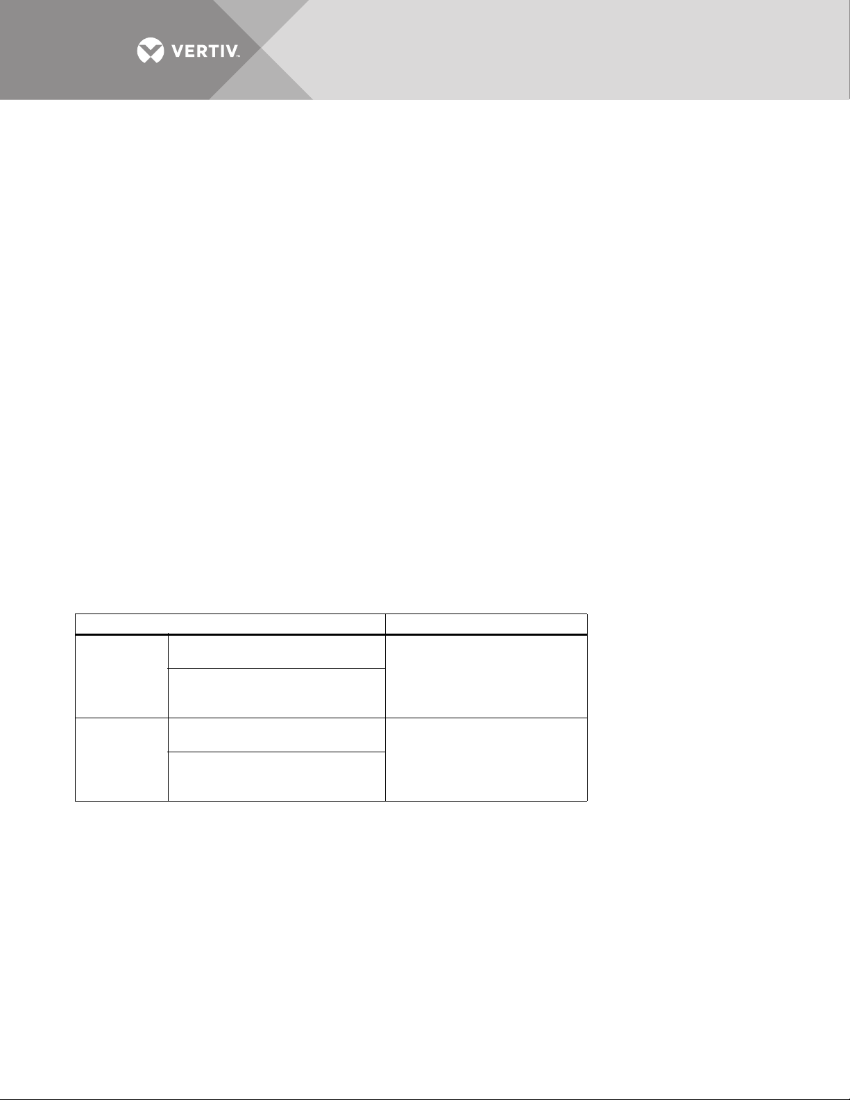
Table 1 Model configurations
Model # Input/Output
ITA2-08KRT208C
8kVA
(208 and
220V)
10kVA
(208 and
220V)
All models above include a rack-mount rail kit, UPS-to-battery cable kit (ITA2-UPSEBCCBL1).
Liebert IS-UNITY-DP Card Included
ITA2-08KRT208
Liebert IS-Unity card sold
separately
ITA2-10KRT208C
Liebert IS-UNITY-DP Card Included
ITA2-10KRT208
Liebert IS-Unity card sold
separately
Single-input configuration
(default),
dual-input is field-configurable
Single-input configuration
(default),
dual-input is field-configurable
Vertiv | Liebert® ITA2™ User Manual | 4
1.3 Appearance and Components
VERTIV
VERTIV
Run
A
l
a
rm
Ent
e
r
E
s
c
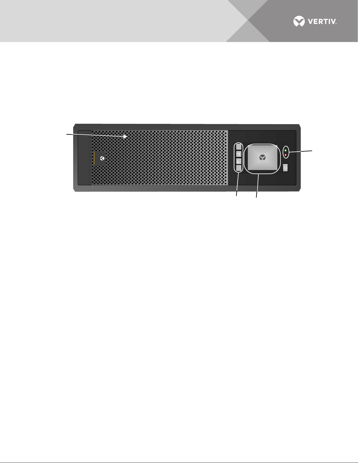
1. Ventilation Holes 2. LED
Indicators
1
4
3
2
Figure 1 shows the controls and other features on the front of the unit. The rear panel and
connections are shown in Figure 2.
1.3.1 Components—Front Panel
As shown in Figure 1, the UPS front panel provides ventilation holes, operation and display panel,
LED indicators and function keys.
Figure 1 UPS front panel
1.3.2 Components—Rear Panel
As shown in Figure 2, the UPS rear panel features parallel/LBS ports, dry contact port, I/O
terminal block, battery terminal block, Liebert IntelliSlot port, USB port, RS-232 port, REPO port
and multi-function port. The Liebert IntelliSlot UNITY-DP™ card is standard.
Vertiv | Liebert® ITA2™ User Manual | 5
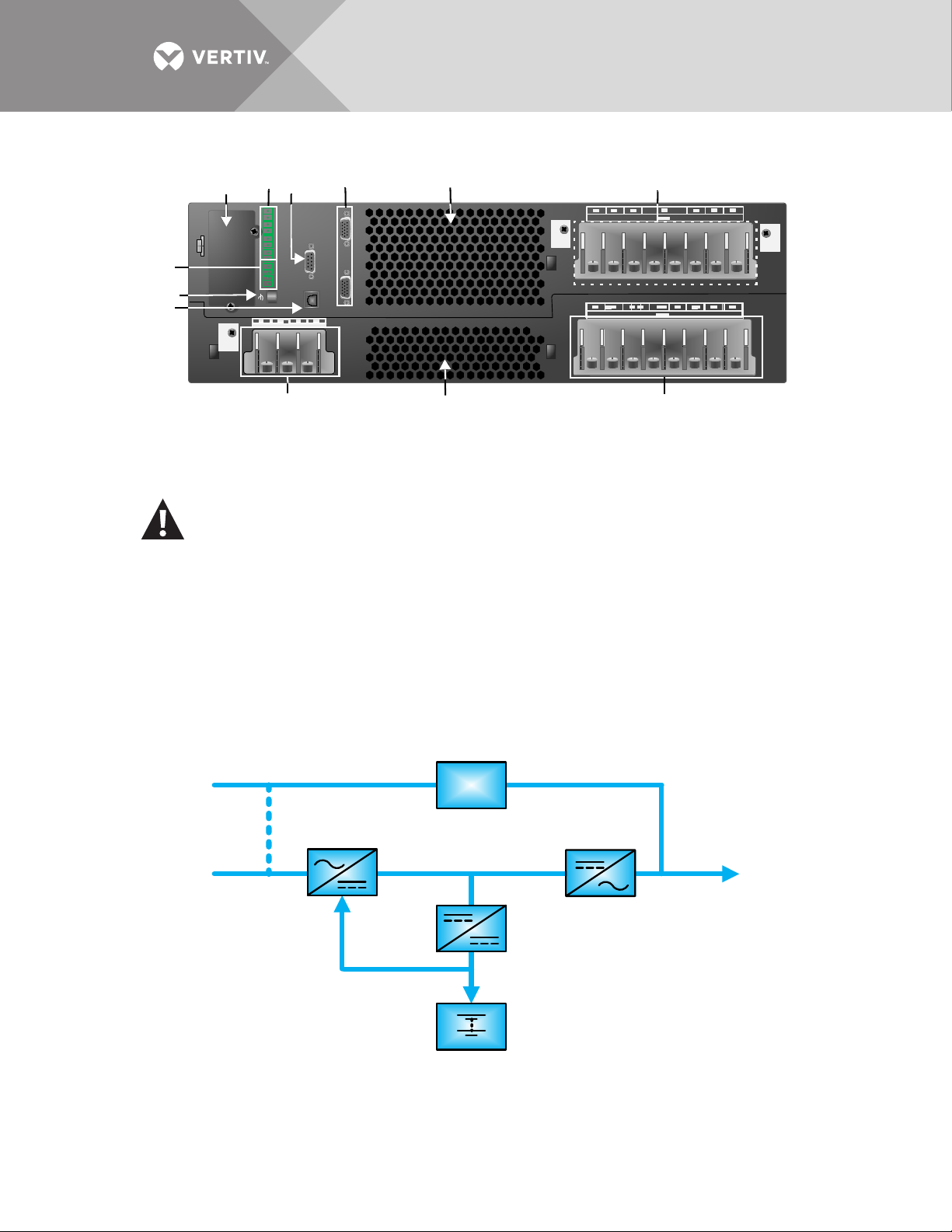
Figure 2 UPS rear panel
REPO
1
2
3
4
6
79
10
11
12
1. Liebert IntelliSlot
Port
2. Dry Contact Port 3. RS-232 Port 4. Parallel/LBS
Port
5. Ventilation Holes 6. AC Output
Te rm in al s
7. AC Input
Te rm in al s
8. Ventilation
Holes
5
8
Battery
Charger
Bypass Input
Mains
Input
Inverter
UPS
Output
Rectifier/PFC
Static
Switch
WARNING
Risk of unauthorized changes and improper service. Can cause property damage, injury or
death.
The Liebert ITA2 has no user-serviceable parts. Contact Vertiv Support at 800-548-2378
in the event of any malfunction that requires service. Unauthorized personnel must not
open the UPS chassis cover.
1.4 Major Components
The UPS is composed of main/bypass input, TVSS and EMI/RFI filters, rectifier/PFC, inverter, DCDC battery charger, static bypass transfer switch, external battery cabinets and main output.
Figure 3 UPS operating principle
Vertiv | Liebert® ITA2™ User Manual | 6

1.4.1 Transient Voltage Surge Suppression (TVSS) and EMI/RFI Filters
These UPS components provide surge protection and filter both electromagnetic interference
(EMI) and radio frequency interference (RFI). They minimize any surges or interference present
in the mains line and protect the sensitive equipment even when on internal bypass power.
1.4.2 Rectifier/Power Factor Correction (PFC) Circuit
In normal operation, the rectifier/power factor correction (PFC) circuit converts mains AC power
to regulated DC power for use by the inverter while ensuring that the wave shape of the input
current used by the UPS is near ideal. Extracting this sine wave input current:
• Ensures efficient use of the mains power.
• Reduces distortion reflected on the mains.
This makes cleaner power available to other devices in the building not protected by the Liebert
ITA2.
1.4.3 Inverter
In normal operation, the inverter utilizes the DC output of the power factor correction circuit and
inverts it into precise, regulated sine wave AC power. When mains power fails, the inverter
receives energy from the battery through the DC-to-DC converter. In both normal mode and
bypass mode, the UPS inverter remains on-line, generating clean, precise, regulated AC output
power.
1.4.4 DC-DC Charger
Whenever the Liebert ITA2 is connected to utility power and the rectifier is operating, the battery
charger receives energy through the internal DC bus (output of rectifier/PFC) and regulates it to
continuously float charge the batteries.
1.4.5 Static Bypass Switch
The Liebert ITA2 static bypass switch provides an alternate path for utility power to the
connected equipment should the UPS have an output overload, overtemperature condition or
any other failure. When UPS output power fails, the Liebert ITA2 automatically transfers the
connected equipment to bypass power through the static bypass.
1.4.6 Battery Cabinets
The Liebert ITA2 utilizes valve-regulated, non-spillable, lead-acid batteries. To maintain battery
design life, operate the UPS in an ambient temperature of 68°F to 77°F (20°C to 25°C). Additional
battery cabinets are available to extend battery run times. For run times, see Tables 13 and 14.
1.5 UPS State and Operation Mode
For the LED indicators introduced in this section, refer to 3.1 - LED Indicators.
The UPS state and operation mode include: Normal Mode, Bypass Mode, Battery Mode, ECO
Mode, Fault state and Maintenance Bypass Mode. The operation schematic diagrams of Normal
Mode, Bypass Mode, Battery Mode and Maintenance Bypass Mode are shown in Figures 4
through 7.
NOTE
Maintenance Bypass Mode is available only when the UPS system includes the optional MBC
cabinet.
Vertiv | Liebert® ITA2™ User Manual | 7
1.5.1 Normal Mode
Battery
Charger
Bypass
Input
Mains
Input
Inverter
UPS
Output
Rectifier/PFC
Static
Switch
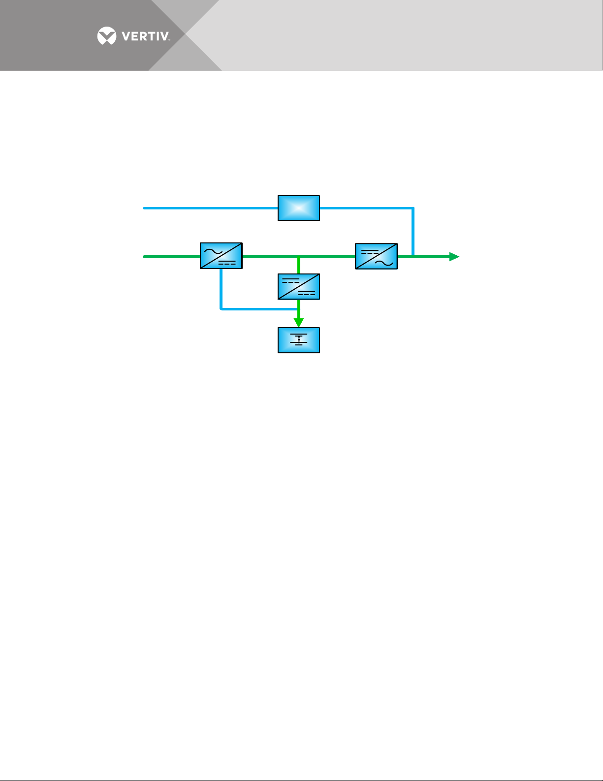
The Liebert ITA2 will operate in Normal Mode and will supply the load with clean, conditioned,
sine wave power when the utility input is normal. In Normal Mode, the battery charger will operate,
charging the battery. The run indicator (green) will be On, the alarm indicator will be Off and the
buzzer will be silent.
Figure 4 Normal Mode
Vertiv | Liebert® ITA2™ User Manual | 8
1.5.2 Bypass Mode
Battery
Charger
Bypass
Input
Mains
Input
Inverter
UPS
Output
Rectifier/PFC
Static
Switch
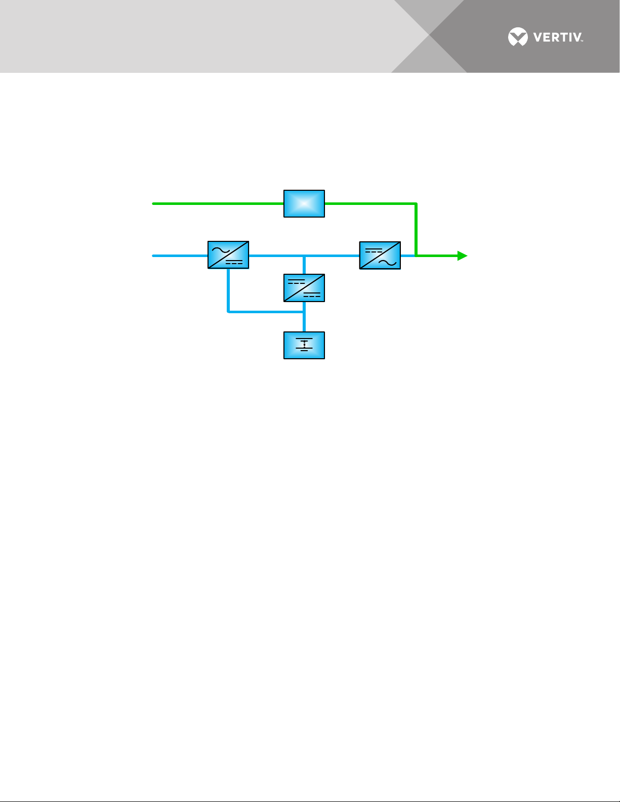
If an overload or a fault occurs during UPS operation in Normal Mode, the UPS will transfer to
Bypass Mode, supplying the load through the bypass source.
In Bypass Mode, the run indicator will be green, the alarm indicator will be yellow and the buzzer
will beep once every second. The Current Screen in the LCD will display On Bypass.
Figure 5 Bypass Mode
NOTICE
Risk of power interruption. Can damage the connected load.
In case of utility failure or utility voltage out of range in Bypass Mode, the UPS will shut down and shut Off
the output power to the load.
1.5.3 Battery Mode
Upon utility failure or voltage out of range, the battery will supply power to the load through the
inverter. In Battery Mode, the run indicator will be green, the alarm indicator will be yellow and the
buzzer will beep once every second. The Current Screen in the LCD will display On Battery.
Vertiv | Liebert® ITA2™ User Manual | 9
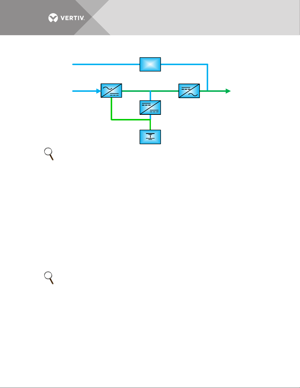
Figure 6 Battery Mode
Battery
Charger
Bypass
Input
Mains
Input
Inverter
UPS
Output
Rectifier/PFC
Static
Switch
NOTE
The battery has been fully charged before shipment. However, transportation and storage will
inevitably cause some capacity loss. Therefore, it is required to charge the battery for 5-8 hours
before putting the UPS into operation for the first time to ensure the adequate battery backup
time.
1.5.4 Auto Restart Mode
Auto restart mode, when enabled (default setting), allows the UPS to automatically restart and
provide conditioned, protected power to the connected equipment after the UPS shut down due
to a depleted battery due to an extended power outage. The Liebert ITA2 has a built-in auto
restart delay of 10 seconds after power is restored that allow the input source to startup other
equipment in the building first and stabilize. The UPS will begin recharging the battery during the
10 second delay.
1.5.5 Eco Mode—Single UPS
Eco Mode is an energy-saving operation mode in which UPS efficiency approaches 99% that can
be used to reduce power consumption. In Eco Mode, the load is powered by bypass if the bypass
voltage is normal; when the bypass voltage is outside the specified range, the load will be
powered by inverter.
NOTE
In Eco Mode, if the bypass failure or abnormal bypass voltage notification appears when the
output is not overloaded, the UPS will transfer to Normal Mode. However, if the bypass failure or
abnormal bypass voltage notification appears when the output is overloaded, the UPS will shut
down the bypass.
1.5.6 Fault State
In Normal Mode, the UPS will transfer to Bypass Mode if the inverter fails or if UPS
overtemperature occurs. In Battery Mode (with no bypass utility), the UPS will shut down and
stop output power if the inverter fails or if a UPS overtemperature occurs. In UPS Fault state, the
alarm indicator (red) will be On, the buzzer will beep continuously and the fault information will be
displayed on the LCD.
Vertiv | Liebert® ITA2™ User Manual | 10
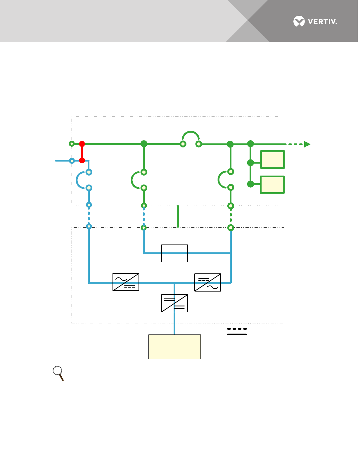
1.5.7 Maintenance Bypass Mode
Charger
System AC
Output
208/120VAC
4W+Gnd
Inverter
Liebert ITA2 Maintenance Bypass Cabinet
Rectifier/PFC
Factory-Installed
Jumper; Remove for
Dual Input
RIB
POD
Port 1
POD
Port 2
Control
Cable
Field-Supplied Wiring
Factory-Supplied Wiring
Liebert ITA2 UPS Cabinet
System AC
Input
208/120VAC
4W+Gnd
MBB
MIB
BIB
Battery
Cabinet(s)
Static
Switch
For maintenance and repair, the load can be switched to Maintenance Bypass through the
optional maintenance bypass, and the power to the load will not be interrupted. The Maintenance
Bypass Breaker is on the front panel of the Maintenance Bypass Cabinet (MBC). For details, refer
to the Liebert ITA2 MBC user manual, SL-26252. The manual is available at Vertiv’s Web site:
www.vertivco.com
Figure 7 Maintenance Bypass Mode
NOTE
The Liebert ITA2 has no user-serviceable parts. If the UPS malfunctions and requires service,
contact Vertiv Support at 800-543-2378 or your local Vertiv representative.
Vertiv | Liebert® ITA2™ User Manual | 11

2.0 SINGLE UPS INSTALLATION AND COMMISSIONING
This chapter introduces the installation, cable connection and commissioning of the single UPS.
Because each site is different, this chapter provides general installation procedures and methods
for the installation engineer who should conduct the installation according to the site conditions
and requirements.
WARNING
Risk of improper installation. Can cause property damage, injury or death.
The UPS must be installed according to the information contained in this chapter by
properly trained and qualified personnel. If any problem is found, contact Vertiv Support
immediately at 800-543-2378.
The UPS must not be powered On without approval of the commissioning engineer.
NOTE
Three-phase, five-wire for power input—The UPS can be connected to three-phase, five-wire (A,
B, C, N, PE) TN, TT and IT AC power distribution system (IEC60364-3).
2.1 Unpacking and Inspection
The 8 and 10kVA models are shipped in a cardboard box. To unpack the UPS:
1. Stand the box upright.
2. Open the carton and remove the packing.
3. Lift out the accessories and set them aside.
4. Lift the UPS out of the box and stand it or lay it aside.
5. Remove the UPS, as shown in Figure 8.
Vertiv | Liebert® ITA2™ User Manual | 12
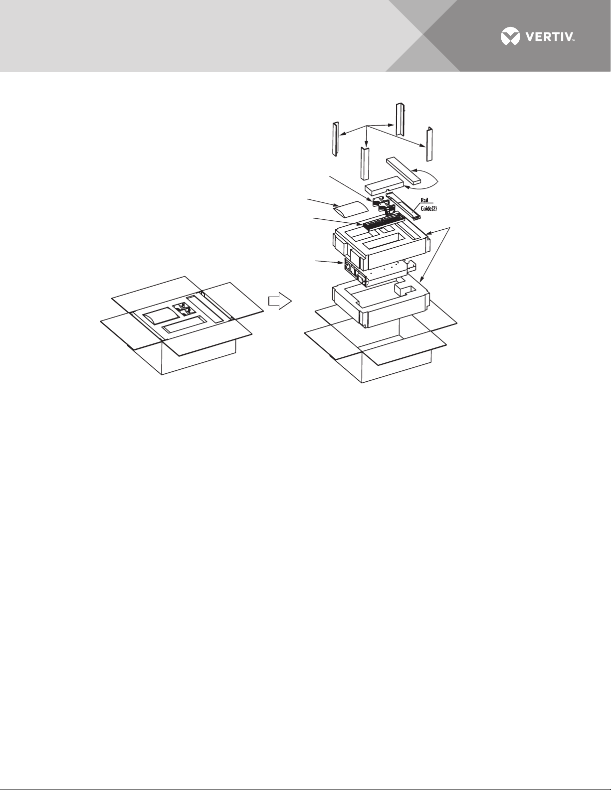
Figure 8 Unpacking cardboard box
Corner
Braces
Protective
Packing
Protective
Packing
Bag of
Hardware
Front
Panel
Liebert ITA2
Support
Base
After the UPS and accessories are unpacked,
1. Inspect the UPS for damage. If any problem is found, file a damage claim with the carrier immediately and
send a copy to Vertiv at:
Vertiv
1050 Dearborn Drive
P.O. Box 29186
Columbus, Ohio 43085 USA
2. Check the accessories and models against the delivery list. If any problem is found, notify your local Vertiv
representative immediately.
2.2 Moving the UPS
The UPS cabinet can be moved manually by an adequate number of personnel or with
mechanical lifting equipment.
NOTICE
Risk of improper transport. Can cause damage to the UPS.
Never attempt to lift or move the Liebert ITA2 with the rack brackets. The brackets and screws are not
designed to be used to lift the unit.
Vertiv | Liebert® ITA2™ User Manual | 13
2.3 Installation Preparation
Wall
UPS
8"
(200mm)
Top view of rack
2.3.1 Location
For proper operation and to extend the UPS life, install the unit in an area with:
•Convenient wiring
• Adequate operator access area
• Good ventilation
• No corrosive gases
• No excessive moisture
• No excessive dust
• Compliance with firefighting requirements
• Operating temperature within the specifications shown in Table 15
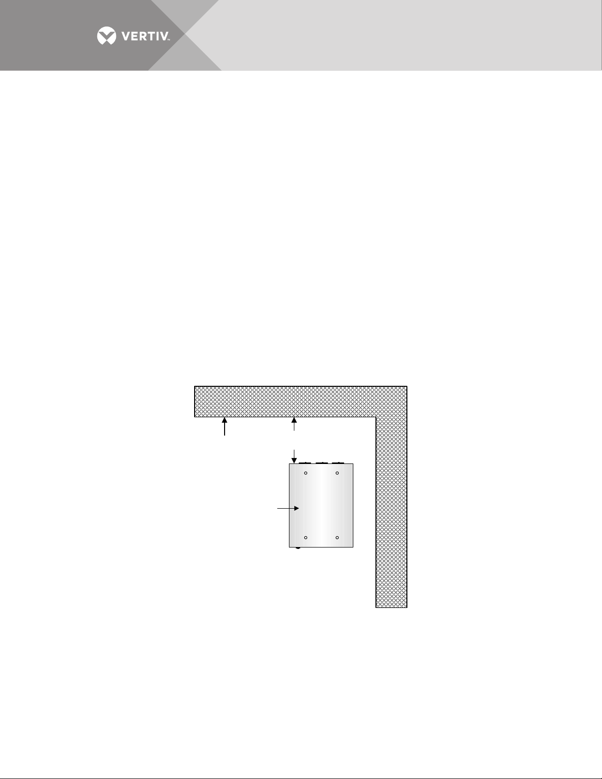
2.3.2 Environmental Requirements
UPS Room
The UPS is designed for indoor installation in a clean, well-ventilated environment with the
ambient temperature within the specifications shown in Tab le 1 5.
The internal fans provide forced air cooling for the UPS. Cooling air enters the UPS through the
front panel, and exhausts the hot air through the back. Maintain at least 8" (200mm) clearance in
the front and rear of the UPS (see Figure 9), to avoid obstructing the UPS ventilation and heat
dissipation.
Figure 9 Installation clearances
Vertiv | Liebert® ITA2™ User Manual | 14

Storage
If the UPS is not installed immediately, it must be stored indoors and protected from excessive
moisture, heat and other harsh conditions. The battery in the external battery cabinet requires
dry, well-ventilated environment for storage with a storage temperature range of 68°F ~ 77°F
(20°C ~ 25°C)
NOTICE
Risk of failure to properly charge batteries. Can cause permanent damage to batteries and void the
warranty.
Batteries will self-discharge during storage. Batteries must be recharged as recommended by the battery
manufacturer. The batteries must be recharged every 3 to 6 months, depending on storage temperature:
• 68-77°F (20-25°C): 6 months
• 78-86°F (26-30°C): 3 months
• 87°F or higher (31°C or higher): 1 month.
2.3.3 Installation Tools
WARNING
Risk of electric shock. Can cause property damage, injury or death.
All tools used to install or maintain the Liebert ITA2 must be insulated. The tools below are
for reference only; follow the all local and national regulations when installing or servicing
the Liebert ITA2.
•Slotted Screwdriver
• Insulated Torque Wrench
• Multimeter
• #3 Phillips Screwdriver
• T10 Torx Screwdriver
• Clip-on Ammeter
2.4 External Protective Devices
A circuit breaker or other protective devices must be installed at the external AC input end of the
UPS. This section provides general guidance for installation by a properly trained and qualified
engineer.
2.4.1 Rectifier and Bypass Input
Overcurrent
An appropriate overcurrent protective device should be installed on the utility input power
distribution, and the current capacity of power cable and the system overload requirements
should be taken into account in installation (see Tab le 2 ).
Dual-Input
In a dual-input system, separate protective devices should be installed for the rectifier and
bypass inputs at the utility input power distribution panel.
Main/Bypass Back-Feed Protection
The UPS has main/bypass back-feed protection function in the event of a fault.
Vertiv | Liebert® ITA2™ User Manual | 15

Earth Leakage Current
The residual current detector (RCD) for the UPS upstream input power distribution should be:
• Sensitive to the DC unidirectional pulse (Level A) in power distribution network
• Insensitive to the transient current pulse
• General sensitivity type, settable: 0.3A ~ 1A
The residual current circuit breaker (RCCB) must be sensitive to the DC unidirectional pulse
(level A) in power distribution network, but insensitive to the transient current pulse, as shown in
Figure 10.
Figure 10 RCCB symbols
When using the earth RCD in a split-bypass system or parallel system, the RCD should be
installed at the upstream input power distribution end to prevent false alarms.
The earth leakage current fed by the RFI filter in the UPS ranges from 3.5mA to 100mA. Vertiv
recommends verifying the sensitivity of each differential device of the upstream input power
distribution and downstream power distribution (to load).
2.4.2 Battery Input
Battery cabinets provided by Vertiv have a built-in overcurrent protective device.
2.4.3 UPS Output
A protective device must be installed for the UPS output power distribution.
2.5 Mechanical Installation
The Liebert ITA2 may be installed in a tower or rack configuration. If the installation includes
batteries or a Maintenance Bypass Cabinet review the user manuals for those components
before beginning to install the Liebert ITA2 UPS. The MBC and battery cabinets should be
installed before the UPS is installed.
2.5.1 Tower Installation
1. Assemble a pair of support bases and a support base extension, as shown in Figure 11.
2. Put the assembly on a flat installation surface.
Vertiv | Liebert® ITA2™ User Manual | 16
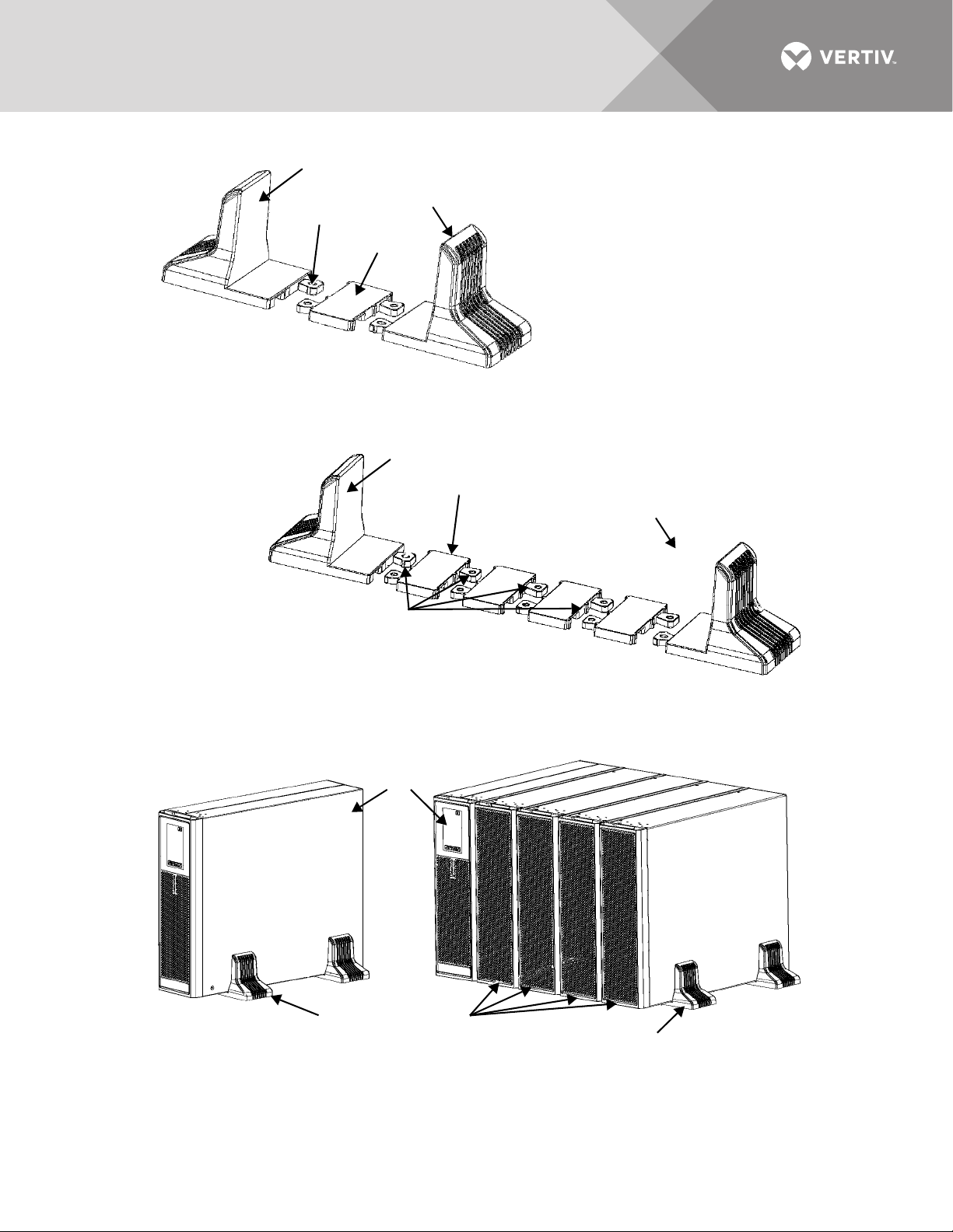
Figure 11 Connecting the support base with support base extension
1
3
2
1
1. Support Base 2. Connector
3. Support Base
1. Support Base 2. Connector
3. Support Base
Extension
1
3
2
1
1
e
1. Support Base 2. UPS
3. Battery Cabinet, 4
2
3
1
3. If one or more battery cabinets will be installed, assemble the necessary number of support bases as
shown in Figure 12.
Figure 12 Assemble the support base for UPS and battery cabinets
4. Place the UPS on the support bases and support base extensions, as shown in Figure 13.
Figure 13 UPS and battery cabinet installation complete
Vertiv | Liebert® ITA2™ User Manual | 17
 Loading...