

Page 1

Liebert®
iCOM CMS™
Installer/User Guide
Intelligent Communication & Monitoring
forLiebertSRC™Mini-SplitSystems
Page 2

The information contained in this document is subject to change
without notice and may not be suitable for all applications. While
every precaution has been taken to ensure the accuracy and
completeness of this document, Vertiv assumes no responsibility
and disclaims all liability for damages resulting from use of this
information or for any errors or omissions. Refer to other local
practices or building codes as applicable for the correct methods,
tools, and materials to be used in performing procedures not
specifically described in this document.
The products covered by this instruction manual are manufactured
and/or sold by Vertiv. This document is the property of Vertiv and
contains confidential and proprietary information owned by Vertiv.
Any copying, use or disclosure of it without the written permission
of Vertiv is strictly prohibited.
Names of companies and products are trademarks or registered
trademarks of the respective companies. Any questions regarding
usage of trademark names should be directed to the original
manufacturer.
Technical Support Site
If you encounter any installation or operational issues with your product, check the pertinent
section of this manual to see if the issue can be resolved by following outlined procedures.
Visit https://www.Vertiv.com/en-us/support/ for additional assistance.
Vertiv™ | Liebert® iCOM CMS™ Intaller/User Guide
Page 3

TABLE OF CONTENTS
1 Getting Started with iCOM CMS 5
1.1 Liebert iCOM CMS has 3 Main Features 5
1.2 What Features Would You Like to Use? 5
1.2.1 Access the web-based user interface 5
1.2.2 Access the BMS protocols 5
1.2.3 Access the mobile cloud/mobile app 5
1.3 iCOM CMS web-based user interface 6
1.3.1 Setpoint and Sensor status 8
1.3.2 Unit Status 8
1.4 Logging-on to iCOMCMS and Unlocking controls 9
1.4.1 Powering-on the cooling unit 9
1.4.2 Powering-off the cooling unit 9
1.4.3 Logging out 9
1.5 Setting general display properties 9
1.6 Setting the date and time 10
1.7 Searching 10
1.8 Using Context-sensitive Help 11
1.9 About iCOM CMS version 11
1.10 Accessing the User, Service and Advanced functions 11
2 User Operation 15
2.1 Viewing setpoints for the cooling unit 15
2.2 Viewing the event log for a cooling unit 15
2.3 Viewing cooling-unit alarms 16
2.3.1 Acknowledging alarms 17
3 Service and Advanced Operation 19
3.1 Editing setpoints for the cooling unit 19
3.1.1 Setting-up Auto Run Mode 20
3.2 Managing Alarm and Warning Notifications 21
3.2.1 Enabling alarm/warning notifications and editing settings 21
3.3 Maintenance scheduling and component run hours 22
3.3.1 Setting Maintenance Dates 22
3.4 External Monitoring and Building-management systems 22
3.4.1 Modbus RTU Set Up 23
3.4.2 Modbus TCP Set Up 23
3.4.3 SNMP Set Up 24
3.5 Connection Settings 25
3.6 Backing-up and Restoring settings 26
3.6.1 Backing-up iCOM CMS settings 26
3.6.2 Restoring iCOMCMS settings 26
3.6.3 Exporting iCOMCMS settings 26
Vertiv | Liebert® iCOM CMS™ Intaller/User Guide | 3
Page 4

3.6.4 Importing iCOMCMS Settings 27
3.6.5 Resetting hardware to factory defaults 27
3.7 Updating iCOMCMS firmware 28
3.7.1 Firmware update using USB drive 29
3.7.2 Firmware update using drag-and-drop 29
3.8 Managing Access Permission and PINS 30
3.9 Generating a Diagnostics Report 30
3.10 Setting unit name, location and serial number 31
3.11 Setting the iCOMCMS Name 31
3.12 Setting the Managing Mode 32
3.13 Managing SSL Certificates 32
3.13.1 Generating a Certificate Signing Request 32
3.13.2 Generating a Self-signed Certificate 33
4 Installing and Connecting iCOMCMS 35
4.1 Mounting iCOMCMS on Thermal-management Unit 35
4.2 Connecting the SRC andCMS ControlBoardswiththeModbusGateway 36
4.3 Setting up Communication withtheWeb-basedUserInterface 39
4.4 Set the Managing Mode to SRC 40
4.5 Enable the Connected SRC Units 40
4.6 Registering with the Administration Portal toAllowMobile-appUsers Access 41
4.7 Setting Up Network Communication 41
4.8 Setting Up BMS serial communication 42
Appendices 43
Appendix A: Technical Support and Contacts 43
Vertiv | Liebert® iCOM CMS™ Intaller/User Guide | 4
Page 5

1 GETTING STARTED WITH ICOM CMS
The web-based user interface for iCOMCMS offers the highest capability for unit control, communication,
and monitoring of Liebert® Thermal Management units. It is available factory-installed on new units and
assemblies or may be retrofitted in existing units. For details on first-time set-up and retro-fit installation,
see Installing and Connecting iCOMCMS on page 35.
1.1 Liebert iCOM CMS has 3 Main Features
• A web-based user interface providing remote connectivity to a unit-level display with full
read/write capabilities.
• BMS connectivity via Modbus RTU, Modbus TCP/IP and SNMP.
• Mobile cloud/Mobile app access to view status and notification information on a mobile device.
NOTE: You can control the unit using the web-based UI, including unit on/off, setpoints, and alarm setup. The mobile app, however, does not allow unit control. It is a read-only interface for notifications.
1.2 What Features Would You Like to Use?
You can use one or all of these features, and the following sections provide an outline of the steps to setup and get started using each one.
1.2.1 Access the web-based user interface
Place iCOMCMS on your corporate network by configuring the network settings using the Connection
Settings menu. See Connection Settings on page 25.
Once set-up, everyone using a computer with corporate-network access and provided with the assigned
IP address can open the web UI in a web browser.
1.2.2 Access the BMS protocols
To configure communication with your building-management system, use the BMS Setup menu. See
External Monitoring and Building-management systems on page 22.
1.2.3 Access the mobile cloud/mobile app
Place iCOMCMS on your corporate network by configuring the network settings using the
ConnectionSettings menu. See Connection Settings on page 25.
Then, register the iCOMCMS cooling unit using the Cloud Setup menu. See Registering with the
Administration Portal toAllowMobile-appUsers Access on page 41.
• Once the unit is registered, the e-mail address you used to register the device will receive a
password-change e-mail with the credentials to log-in to the iCOMCMS Administration Portal
(www.icomcms.com) and the mobile app.
1 Getting Startedwith iCOM CMS
5
Page 6

• Visit the Administration Portal at icomcms.com, and log-in to manage the registered devices
and mobile-app users as follows:
• Create a division.
• Create a building and assign the building to a division.
• Assign the registered iCOMCMS unit to a building.
• Create users, define the user’s role (Administrator, Mobile-app only), set-up e-mail or
SMS-text notifications, and assign buildings to the user, which determines what units
they can view in the mobile app.
• The mobile-app users will get an e-mail with log-in credentials, and can download the
iCOMCMS mobile application and log in to receive notifications.
1.3 iCOM CMS web-based user interface
The web-based user interface speeds set up and installation and simplifies control of Liebert® cooling
units.
• User, service and advanced menus are password-protected to prevent unauthorized changes
to cooling-unit operation. See Logging-on to iCOMCMS and Unlocking controls on page 9.
• iCOMCMS ships with default settings for efficient and effective operation of most cooling-units
and is easily configured to meet any need.
• iCOMCMS requires a Google Chrome web browser version 50.0.xx or higher.
Figure 1.1 on the facing page, shows the controls and options available on the main display.
6
Vertiv™ | Liebert® iCOM CMS™ Intaller/User Guide
Page 7
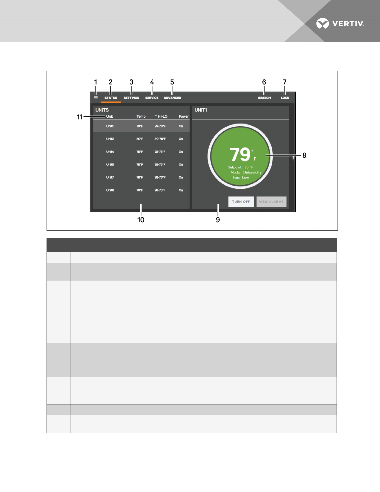
Figure 1.1 iCOM CMS web-based user interface
ITEM DESCRIPTION
1 Menu icon. When unlocked, displays set-up, control options andmenu depending on the password level used.
2
Status view. When you log on, the iCOMCMS-controlled units and their status are listed on the main display. Clickingthe
status icon toggles between the status and alarm summary.
Settings view. When selected, the settings options are listed on the main display. Options are:
• Display Preferences, see Setting general displayproperties on page 9.
• Date/Time Setup, see Setting the date and time on page 10.
3
• iCOM-CMSsettings are listed when you are logged-in at the “advanced” level, see:
• Setting the iCOMCMS Name on page 31.
• Setting the Managing Mode on page 32.
• Managing SSL Certificates on page 32
Service view. When selected, the last and next preventive maintenance (PM) are listed next to the c onnected units.
4
SeeMaintenance schedulingandcomponent run hours on page 22.
You must be logged-on at the “Service” or “Advanced” level to access the service icon.
See Logging-on to iCOMCMS and Unlocking controls on page 9.
Advanced view. When selected, advanced-level options are available on the menu.
5
You must be logged-on at the “Advanced” level to access the advanced icon.
See Logging-on to iCOMCMS and Unlocking controls on page 9.
6 Search. Opens the “search” term-entry box. See Searching on page 10.
7
Lock/Unlock. Indicates that the options/menus at the level at which you are logged-on (user, service or advanced) are
accessible. See Logging-on to iCOMCMSandUnlocking controls on page 9.
1 Getting Startedwith iCOM CMS
7
Page 8
ITEM DESCRIPTION
8
9
10
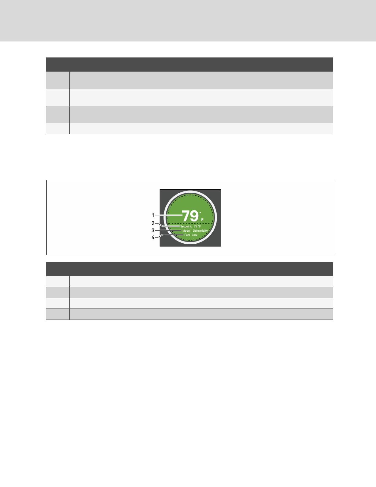
11 Unit list. A list of monitored units. Clicking a unit displays the setpoint andstatus summary for that unit.
Setpoint and Status summary. Summary display of setpoints and environmentalconditions of the unit. See Setpoint and
Sensor status on page 8.
Secondary-content panel. When accessing settings/configuration via the menus, the settings display in the right,
“secondary” panel.
Primary-content panel. When accessing settings/configuration viathe menus, a list of options/categories displayin the
left, “primary” panel.
1.3.1 Setpoint and Sensor status
The dial in the status panel displays setpoints and environmental conditions for the unit at a glance.
Figure 1.2 Status dial
ITEM DESCRIPTION
1 Temperature-sensor reading. Current temperature reading at the unit.
2 Temperature setpoint. Current temperature setpoint.
3 Operatingmode. Current operating mode of the unit.
4 Fan mode. Current operating mode of the fan.
1.3.2 Unit Status
The unit status list in the main status panel displays unit-specific settings and parameters at a glance.
The list shows current temperature-sensor reading and the high/low temperature readings for each
monitored unit. Selecting a unit in the list displays more information about that unit in the status dial, see
Figure 1.2 above.
8
Vertiv™ | Liebert® iCOM CMS™ Intaller/User Guide
Page 9

1.4 Logging-on to iCOMCMS and Unlocking controls
The factory-default password for user, service and advanced login are provided. We recommend you
change passwords as necessary to prevent unauthorized changes. See Managing Access Permission and
PINS on page 30.
• Default User password = 1490
• Default Service password = 5010
• Default Advanced password = 2210
To log-on and unlock iCOMCMS:
1. Open the iCOMCMS web interface in your browser.
The log-in screen opens.
2. Type the password, and click Sign In.
Depending on the user level selected, the user/service/advanced options are accessible. See
Accessing the User, Service and Advanced functions on page 11.
1.4.1 Powering-on the cooling unit
1. In the unit list on the status panel, click .
The POWER UNIT CONTROL dialog opens.
2. Click On.
The cooling unit starts.
1.4.2 Powering-off the cooling unit
1. In the unit list on the status panel, click .
The POWER UNIT CONTROL dialog opens.
2. Click Off.
The cooling unit powers-off.
1.4.3 Logging out
To log-out, click the lock icon.
The log-in screen displays.
1.5 Setting general display properties
1. On the menu bar, click SETTINGS, then Display Preferences in the settings list.
The DISPLAY PREFERENCES panel displays.
2. Select the settings and click Save.
• Click Cancel to discard the changes.
1 Getting Startedwith iCOM CMS
9
Page 10

Display-preferences fields
Theme
Selects the color theme for the display.
Measurement System
Selects the units of measurement.
Inactivity Timer
Time to elapse before display logs-off.
Date Format
Display format for the date.
Time Format
Display format for the time.
1.6 Setting the date and time
The correct date and time is critical for warnings, alarms, and scheduling.
1. On the menu bar, click SETTINGS, then Date/Time Setup in the settings list.
The DATE/TIME SETUP panel displays.
2. Select the settings.
3. Click Save.
• Click Cancel to discard the changes.
Date/Time set-up options
Time Zone
Selects the time zone.
NTP Server #X
When NTP is enabled, the address of the server(s) to which the unit refers for the time protocol,
where X=designates a reference number for the server.
1.7 Searching
Use the display search to find the location of settings options.
1. On the menu bar, click SEARCH.
The term-entry box opens.
• Click Search again to close the term-entry box.
2. Type the term and press Enter.
A list of locations that contain the searched term opens.
3. Click an item to open the panel for the selected location.
10
Vertiv™ | Liebert® iCOM CMS™ Intaller/User Guide
Page 11

1.8 Using Context-sensitive Help
Clicking the Help icon, , on the right-hand side of the display opens the Help drawer with information
about the panel or dialog currently on the display. You can use search in the Help to find further
information.
To close the Help drawer, click the close arrow, again.
1.9 About iCOM CMS version
The version, build, and other firmware information may be helpful when servicing or troubleshooting.
1. Click ,
The menu opens.
2. Click About.
The ABOUT panel opens.
1.10 Accessing the User, Service and Advanced functions
The iCOMCMS operating functions that monitor and control a cooling unit are accessed via the icons in
the header and the menus.
NOTE: You must be logged-in with the appropriate level and password to access the menu options for
user-, service- and advanced-specific functions. See Logging-on to iCOMCMS and Unlocking controls
on page 9.
To access menu functions:
Click the menu icon, .
Depending on the function level at which you are logged-in, the menu opens. The following lists describe
the available options on each menu.
User-level menu options
Setpoints
Opens the SETPOINTS panel. See Viewing setpoints for the cooling unit on page 15.
Event Log
Opens the EVENT LOG panel. See Viewing the event log for a cooling unit on page 15.
About
Opens the ABOUT panel. See About iCOM CMS version on page 11.
Support & Services
Opens the SUPPORT & SERVICES panel.
1 Getting Startedwith iCOM CMS
11
Page 12

Service-level Menu Options
Setpoints
Opens the SETPOINTS panel. See Editing setpoints for the cooling unit on page 19.
Set Alarms
Opens the SET ALARMS panel. See Managing Alarm and Warning Notifications on page 21.
Event Log
Opens the EVENT LOG panel. See Viewing the event log for a cooling unit on page 15.
BMS Setup
Opens the BMS SETUP options:
• Modbus—See Modbus RTU Set Up on page 23.
• SNMP—See SNMP Set Up on page 24.
Cloud Setup
Opens the CLOUD SETTINGS panel. See Registering with the Administration Portal
toAllowMobile-appUsers Access on page 41.
Connection Settings
Opens the DISPLAY CONNECTIONS panel. See Connection Settings on page 25.
Settings Management
Opens the SETTINGS MANAGEMENT options:
• Backup & Restore—See Backing-up and Restoring settings on page 26.
• Import & Export—See Importing iCOMCMS Settings on page 27, and Exporting iCOMCMS
settings on page 26.
• Factory Reset—See Resetting hardware to factory defaults on page 27.
Load Firmware
Opens the FIRMWARE UPGRADE PARAMETERS panel. See Updating iCOMCMS firmware on page
28.
About
Opens the ABOUT panel. See About iCOM CMS version on page 11.
Support & Services
Opens the SUPPORT & SERVICES panel.
12
Vertiv™ | Liebert® iCOM CMS™ Intaller/User Guide
Page 13

Advanced-level Menu Options
Setpoints
Opens the SETPOINTS panel. See Editing setpoints for the cooling unit on page 19.
Set Alarms
Opens the SET ALARMS panel. See Managing Alarm and Warning Notifications on page 21.
Event Log
Opens the EVENT LOG panel. See Viewing the event log for a cooling unit on page 15.
BMS Setup
Opens the BMS SETUP options:
• Modbus—See Modbus RTU Set Up on page 23.
• SNMP—See SNMP Set Up on page 24.
Cloud Setup
Opens the CLOUD SETTINGS panel. See Registering with the Administration Portal
toAllowMobile-appUsers Access on page 41.
Connection Settings
Opens the DISPLAY CONNECTIONS panel. See Connection Settings on page 25.
Settings Management
Opens the SETTINGS MANAGEMENT options:
• Backup & Restore—See Backing-up and Restoring settings on page 26.
• Import & Export—See Importing iCOMCMS Settings on page 27, and Exporting iCOMCMS
settings on page 26.
• Factory Reset—See Resetting hardware to factory defaults on page 27.
Load Firmware
Opens the FIRMWARE UPGRADE PARAMETERS panel. See Updating iCOMCMS firmware on page
28.
Manage Passwords
Opens the MANAGE PASSWORDS panel. See Managing Access Permission and PINS on page 30.
About
Opens the ABOUT panel. See About iCOM CMS version on page 11.
Support & Services
Opens the SUPPORT & SERVICES panel. Includes the option to create a diagnostics report to help
with technical-support calls. See Generating a Diagnostics Report on page 30.
1 Getting Startedwith iCOM CMS
13
Page 14

This page intentionally left blank
14
Vertiv™ | Liebert® iCOM CMS™ Intaller/User Guide
Page 15

2 USER OPERATION
2.1 Viewing setpoints for the cooling unit
NOTE: User-level access allows only viewing of setpoints. To adjust setpoints, you must have serviceor advanced-level access. See Editing setpoints for the cooling unit on page 19.
To view the setpoints:
1. Click > Setpoints.
The SETPOINTS panel opens.
2. Click the name of the unit for the setpoints you want to see.
The detail panel displays the setpoints for that unit.
Setpoints—user level
Temperature
Temperature that the unit maintains via cooling/reheat.
Fan Speed
Indicates the selected fan speed.
Run Modes
Indicates the operating mode of the unit.
2.2 Viewing the event log for a cooling unit
The event log is a list by date/time, unit, event type for all generated events and alarms and includes the
PIN ID for user-generated events and comments. Selecting an event log displays details about the event.
To view the event log:
1. Click > Event Log.
The EVENT LOG opens.
2. Click an event to display the detailed information.
Event-log fields
When
The date and time the event occurred.
2 User Operation
15
Page 16

Unit
The cooling unit to which the event is associated.
Description
Description of the event.
PIN ID
The name of the user that made a user-generated event or comment.
Event details
Date/Time
The date and time the event occurred.
Unit
The cooling unit to which the event is associated.
Description
Description of the event.
PIN ID
The name of the user that made a user-generated event or comment.
2.3 Viewing cooling-unit alarms
The ALARMS SUMMARY lists active alarm and warning events for the cooling unit.
To view the alarm summary:
1. On menu bar, click STATUS, to toggle between the status and alarm summaries.
The ALARMS SUMMARY displays in the primary panel, and the ALARMS list displays in the
secondary panel.
2. Click a unit to display the alarms list for that unit.
3. Click an alarm to display the ALARM DETAILS panel, described in Alarm/Warning detail fields
on page 17.
Alarm list fields
When
Time elapsed since the event was logged.
Description
Description of the event.
16
Vertiv™ | Liebert® iCOM CMS™ Intaller/User Guide
Page 17

2.3.1 Acknowledging alarms
Once acknowledged, an event remains active until the situation that triggered the event is resolved.
NOTE: The High Water alarm event and the Smoke Detected alarm event (if smoke-detector option is
included) automatically power-off the cooling unit.
To acknowledge an alarm:
1. On the ALARMS list, click an alarm/warning.
The alarm detail panel displays.
2. On the alarm-detail, click Acknowledge.
NOTE: Acknowledging alarm events does not clear them. To clear an issue, it must be corrected, reset
automatically by the controller, or reset manually.
Alarm/Warning detail fields
Event Type
The type of event.
Status
Current status of the event.
Date/Time
Date and time the event was logged.
Duration
Length of time the event is active.
2 User Operation
17
Page 18

This page intentionally left blank
18
Vertiv™ | Liebert® iCOM CMS™ Intaller/User Guide
Page 19

3 SERVICE AND ADVANCED OPERATION
NOTE: With the exception of managing passwords, which is only available to the advanced-level user,
the service and advance menu options are the same.
3.1 Editing setpoints for the cooling unit
Setpoints are the means by which cooling-unit operation is controlled.
NOTE: Setpoint adjustment is only available via the web-based UI (and the wall-mounted controller).
You cannot modify setpoints using the mobile app.
NOTE: The default minimum difference between heating and cooling setpoints is 5°F (2°C), and does
not allow the heating and cooling setpoints to be set inside this differential. To select setpoints for that
do not automatically adjust to the minimum difference, this differential must be zero. We recommend
that you set the differential to zero at system start-up. See Setting the Temperature Differential on
page 20.
To edit the setpoints:
1. Click > Setpoints.
The SETPOINTS panel opens.
2. Adjust the setpoint options, then click Save.
The setpoint is updated.
• Click Cancel to discard the changes.
Setpoint options
Temperature
Temperature that the unit maintains via cooling/reheat.
Fan Speed
Selects the fan speed.
NOTE: Auto fan-speed may only be set via the wall-mounted thermostat.
Run Modes
Selects the operating mode of the unit. Options are:
• Cooling
• Heating
• AI (Auto). See Setting-up Auto Run Mode on page 20.
• Fan
• Dehumidify—Not Supported. Do Not Use.
3 Service and Advanced Operation
19
Page 20
3.1.1 Setting-up Auto Run Mode
To properly navigate communication between the web UI and the wall-mounted thermostat controls, a
2-step procedure is required:
• At the thermostat, set the temperature differential to 0º (zero).
• On the web UI, set the heating and cooling setpoints, then the AI run mode.
Setting the Temperature Differential
The default minimum difference between heating and cooling setpoints is 5°F (2°C), and does not allow
the heating and cooling setpoints to be set inside this differential. To select setpoints for that do not
automatically adjust to the minimum difference, this differential must be zero.
NOTE: If you are having an issue with discrepancies in the setpoints and readings, and setting the
temperature differential does not help, please contact technical support at 1-800-543-2778.
1. At the wall-mounted thermostat, open the flip door and press twice until flashes in
the Function Settings section of the display.
2. Press to set the differential to 0°, then press .
3. Press to exit the function set-up.
Setting Heating, Cooling Setpoints and AI Run Mode
Before selecting AI (Auto) run mode, you must set the heating and cooling setpoints to the same value.
You must be in the run mode of the setpoint when setting it.
1. Make sure the minimum difference between setpoints is 0°. See Setting the Temperature
Differential on page 20.
2. Select heating run mode and set the heating setpoint on the web UI:
• Click > Setpoints, then select the unit to configure.
• In Run Mode, select Heating.
• In Fan Speed, select the fan speed to use.
• In Temperature, select the temperature setpoint.
• Click Save.
3. Select cooling run mode and set the cooling setpoint on the web UI:
• In Run Mode, select Cooling.
• In Fan Speed, select the fan speed to use.
• In Temperature, select the temperature setpoint.
• Click Save.
4. In Run Mode, select AI, then click Save.
The status dial displays “AI” for about 2minutes, and the wall-mounted thermostat is un-
responsive to button presses during this time while the configuration is communicating. After
that, the web UI displays the run mode currently in use, and the wall-mounted thermostat
indicates “AUTO” mode.
20
Vertiv™ | Liebert® iCOM CMS™ Intaller/User Guide
Page 21

3.2 Managing Alarm and Warning Notifications
Events are notifications of operating status for the cooling unit, its components, and auxiliary devices. All
events are recorded in the Event Log, and alarm and warning events are also displayed on the alarm
summaries. See Viewing the event log for a cooling unit on page 15, and Viewing cooling-unit alarms on
page 16.
The EDIT ALARMS panel, lists the configurable notification events for the selected unit. You can modify
these events and the criteria that trigger alarms including:
• Critical thresholds
• Enable/Disable alarm
NOTE: To adjust alarm settings, you must have service- or advanced-level access.
3.2.1 Enabling alarm/warning notifications and editing settings
To adjust alarm settings, you must have service- or advanced-level access.
1. Click > Set Alarms.
The EDIT ALARMS list opens.
2. Click a unit in the SET ALARMS panel.
The configurable alarms for the unit display.
3. Click an alarm in the list.
The EDIT ALARM panel opens.
4. Adjust the settings and click Save.
Edit Alarm panel fields and options
Alarm/Warning switch
Logging and notification level of the event.
NOTE: Warning events do not trigger alert notifications (via e-mail, SMS, and Push) on the mobile
application.
Enabled/Disabled switch
Enables/Disables notification at the cooling unit’s iCOM display and on the web-based UI.
Click the switch to set On or Off.
NOTE: When disabled, events are not logged or displayed and visual/audible alarm notifications are not
made.
Threshold
Reading at which the alarm is triggered.
3 Service and Advanced Operation
21
Page 22

3.3 Maintenance scheduling and component run hours
You can view and configure maintenance dates for each unit by clicking the Service button. The left
panel displays each unit, along with the date of its last performed maintenance and next schedule
maintenance.
Clicking a unit displays the last and next maintenance dates in the right panel. You can select and save
the maintenance last and next maintenance dates for the SRC unit. See Setting Maintenance Dates on
page 22.
Service panel fields
Unit
Unit name.
Last PM
Last scheduled maintenance for the unit.
Next PM
Next scheduled maintenance for the unit.
3.3.1 Setting Maintenance Dates
1. On the menu bar, click SERVICE.
The SERVICE panel opens.
2. Select a unit in the SERVICE panel.
3. In the COMPONENTS panel, select a date for the last and/or next scheduled maintenance,
then click Save.
Maintenance-date fields
Last Maintenance
Date of the previous scheduled preventive maintenance for the unit.
Next Maintenance
Date of the next scheduled preventive maintenance for the unit.
3.4 External Monitoring and Building-management systems
NOTE: Some Building Management Systems can be configured to send continuous updates for
setpoints, which often results in setting the same value. To avoid a back-up with iCOMCMS and loss
or write values, configure the BMS to write device configuration no more than once per minute.
22
Vertiv™ | Liebert® iCOM CMS™ Intaller/User Guide
Page 23

3.4.1 Modbus RTU Set Up
NOTE: The protocol willnot work with the control board’s default IP address: 169.254.24.7. Make sure a
Static or DCHP address is set. See Connection Settings on page 25.
External monitoring can be performed via Modbus serial connection.
1. Click > BMS Setup.
The BMS SETUP panel displays.
2. Select Modbus.
The MODBUS panel displays.
3. In the Interface field, select Modbus RTU.
4. Select the Modbus RTU settings, then click Save.
Modbus RTU communication settings
Interface
Selects type of Modbus communication.
Access Level
Selects read-only or read/write access.
Node ID
Modbus node number (1 to 247).
Data Rate
Selects rate of Modbus communication.
Parity
Selects type of communication parity check.
Stop Bits
Selects number of communication stop bits.
3.4.2 Modbus TCP Set Up
External monitoring can be performed via Modbus TCP connection.
NOTE: The protocol willnot work with the control board’s default IP address: 169.254.24.7. Make sure a
Static or DCHP address is set. See Connection Settings on page 25.
1. Click > BMS Setup.
The BMS SETUP panel displays.
2. Select Modbus.
The MODBUS panel displays.
3 Service and Advanced Operation
23
Page 24

3. In the Interface field, select Modbus TCP.
4. Select the Modbus TCP settings, then click Save.
Modbus TCP communication settings
Interface
Selects type of Modbus communication.
Access Level
Selects read-only or read/write access.
Port
Modbus port number.
Max Concurrent Clients
Maximum number of users that may access the cooling unit via the remote application at the same
time.
Network Access
Selects the level of network access via Modbus.
• Open = no access limits.
• Same Subnet = only accessible by clients on the same subnet.
• Trusted IP list = only accessible by trusted IP addresses, set in Trusted IP field.
Trusted IP #1 – 5
IP addresses with “trusted” network access.
3.4.3 SNMP Set Up
1. Click > BMS Setup > SNMP.
The SNMP panel displays.
2. In the Enabled field select Yes., then click Save.
The following options appear in the left panel:
• SNMPv1V2c Access Hosts
• SNMPv1 Trap Targets
3. Click SNMPv1V2c Access Hosts to view, edit, or add access hosts.
4. Click SNMPv1 Trap Targets to view, edit, or add trap targets.
5. In Authentication Trap, select Enabled, then click Save.
SNMP communication settings
Enabled
Enables/Disables SNMP communication option.
24
Vertiv™ | Liebert® iCOM CMS™ Intaller/User Guide
Page 25

SNMPv1/v2c Access
Enables/Disables SNMP access.
Authentication Trap
Enables/Disables SNMP authentication traps.
Device Name
Object name of the managed device.
3.5 Connection Settings
Configures the Ethernet connection between the unit and the iCOMCMS interface(s).
1. Click > Connection Settings.
The DISPLAY CONNECTIONS list opens.
2. In the Connection Type list, select the connection to configure.
3. In the display-connection PROPERTIES panel, click to toggle DHCP or Static mode.
• If you select DHCP, go to step 5.
• If you select Static, continue with the next step.
4. For static mode, enter the address, netmask, gateway and DNS-server settings.
5. Click Save.
Display-connection options
Mode
IP assignment type.
MAC Address
Media access control. (Read-only.)
IP Address
Network address of the iCOMCMS display/app.
Netmask
Divides IP addresses in subnet.
Gateway
IP address to the gateway to other subnets.
DNS Servers
IP addresses of the DNS servers for the organization.
3 Service and Advanced Operation
25
Page 26
3.6 Backing-up and Restoring settings
iCOMCMS settings may be saved to a local disk or USB drive, and the saved files may exported or
imported to restore iCOMCMS if it is replaced or if a problem occurs. You can import and export
configuration settings to apply the configuration to other units, and you can also return iCOMCMS to
factory-default settings.
3.6.1 Backing-up iCOM CMS settings
Save a copy of the settings in a descriptively named file. Use a back-up file to restore the unit settings in
the event of a failure.
NOTE: Backing-up the iCOMCMS settings does not save settings stored on the cooling unit’s iCOM
display, including setpoints, alarm settings, and sensor calibration. The back-up file also does not save
the cloud-registration status.
1. Click > Settings Management > Backup & Restore.
The BACKUP & RESTORE panel opens.
2. Select the Location to which the backup will be saved.
NOTE: Only a single back-up file may be saved in one location/on one USB drive. Saving to the same
location/drive overwrites the previous file.
3. Click Backup in the lower-right corner, then OK in the confirmation dialog.
The back-up file is saved and a notification indicates that back up is successful.
• Remove the USB drive from the port if used.
3.6.2 Restoring iCOMCMS settings
Copy the settings from a back-up file to return iCOMCMS function to what it was before the problem or
failure. The settings may be restored from a file on the local disk or a USB drive.
1. Click > Settings Management > Backup & Restore.
The BACKUP & RESTORE panel opens.
2. Click the Location from which the settings will be restored.
3. Click Restore in the lower-right corner, then OK in the confirmation dialog.
The settings are restored from the file, a notification indicates that restoration is successful,
and the display restarts.
• Remove the USB drive from the port if used.
3.6.3 Exporting iCOMCMS settings
Export a copy of the settings to a descriptively named file. Use exported settings to import the
configurations into other units.
NOTE: Exported settings do not include the settings stored on the cooling unit’s iCOM display,
including setpoints, alarm settings, and sensor calibration.
1. Click > Settings Management > Import and Export.
The IMPORT & EXPORT panel opens.
26
Vertiv™ | Liebert® iCOM CMS™ Intaller/User Guide
Page 27

2. Select the Location to which the export will be saved.
NOTE: Only a single file may be saved in one location/on one USB drive. Saving to the same
location/drive overwrites the previous file.
3. Click Export in the lower-right corner, then OK in the confirmation dialog.
The export file is saved.
• Remove the USB drive from the port if used.
3.6.4 Importing iCOMCMS Settings
Import the settings from another unit to simplify configuring multiple units. The settings may be imported
from a file on the local disk or a USB drive.
1. Click > Settings Management > Import and Export.
The IMPORT & EXPORT panel opens.
2. Click the Location from which the settings will be imported.
3. Click Import in the lower-right corner, then OK in the confirmation dialog.
The settings are imported.
• Remove the USB drive from the port if used.
3.6.5 Resetting hardware to factory defaults
There are two methods of performing a hardware factory reset, which returns the control board to the
factory-default settings for panel customization, display network settings, BMS settings, and custom
labels.
NOTE: The cloud registration status and connection settings are not reset when resetting to factory
defaults.
• Hardware-button reset
• Factory reset via the web UI.
Hardware factory reset using the button on the control board
1. Locate the 2 buttons on the CMS control board, see Figure 3.1 on the next page.
2. Press the right button (item2), then immediately press-and-hold the left button (item3) for at
least 5seconds.
The LED on the control board (item 1) turns blue and flashes 5 times to indicate the 5-second
countdown.
The factory-default settings are restored and the display restarts.
3 Service and Advanced Operation
27
Page 28
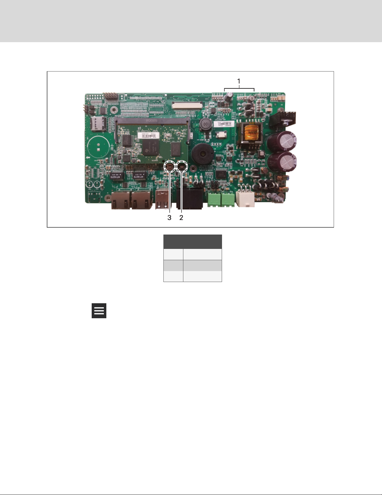
Figure 3.1 Hardware-reset buttons on the control board
ITEM DESCRIPTION
1 LED
2 Button
3 Button
Hardware factory reset using the web UI
1. Click > Settings Management > Factory Reset.
The FACTORY RESET panel opens.
2. Click OK in the lower-left corner.
The factory-default settings are restored and the display restarts.
3.7 Updating iCOMCMS firmware
The firmware may be updated by two methods:
• USB drive
• Drag-and-drop.
NOTE: If the update takes more than 1 minute, the interface may timeout before the firmware update
completes.
28
Vertiv™ | Liebert® iCOM CMS™ Intaller/User Guide
Page 29
3.7.1 Firmware update using USB drive
1. Download and extract the firmware file, .xbp, to a blank USB thumb drive.
NOTE: The USB thumb drive must be blank other than the .xbp firmware file.
2. Plug the USB drive directly into the USB port on the CMS control board.
3. On the iCOMCMS interface, click > Load Firmware > USB.
The USB panel displays. The control board reads the version information of the new firmware
on the USB drive and displays it at the top of the screen, and the Start Upgrade field becomes
accessible.
NOTE: Typically, the reading the new firmware version takes approximately 20 seconds, but may take
longer.
4. Click Start Upgrade.
The firmware is updated, the control board reboots, and the display restarts.
NOTE: The update process may take a few minutes to complete.
3.7.2 Firmware update using drag-and-drop
1. Download the firmware file, .xbp, and save to computer/laptop that is directly-connected to the
CMS control board with an Ethernet cable and is used to access the web UI.
2. On the laptop/computer, open the folder in which the firmware file is located.
3. On the iCOMCMS web UI, click > Load Firmware > Upload Firmware.
The UPLOAD FIRMWARE panel displays.
4. Drag and drop the firmware file to the space outlined on the web interface.The control board
reads the version information of the new firmware and displays it at the top of the screen, and
the Start Upgrade field becomes accessible.
NOTE: Reading the new firmware version may take a few minutes.
5. Click Start Upgrade.
The firmware is updated, the control board reboots, and the display restarts.
NOTE: The update process may take a few minutes to complete.
3 Service and Advanced Operation
29
Page 30
3.8 Managing Access Permission and PINS
NOTICE
Risk of loss-of-access to iCOMCMS. Can cause operational problems.
When a PIN is changed, make sure you record the new PIN and inform authorized users.
Three roles with passwords/personal identification numbers (PINs) provide access permission and are set
with factory-default values. You can change the value of each PIN so that only the users that know the
current PIN may access the functions that it unlocks.
The factory-default PINs are:
• Default User PIN = 1490
• Default Service PIN = 5010
• Default Advanced PIN = 2210
NOTE: To change PIN values, you must use the currently-assigned Advanced PIN to display the
Manage Passwords option on the menu.
To change a PIN:
1. Click > Manage Passwords.
The MANAGE PASSWORDS panel and secondary, properties panel open.
2. On MANAGE PASSWORDS, click the role to change.
3. On the secondary panel, type a new password then re-enter to confirm it, and click Save.
The updated PIN is saved.
• Click Cancel to discard the change.
30
3.9 Generating a Diagnostics Report
When logged-in as an advanced user, you can generate a diagnostics report that is helpful for
troubleshooting when sent to technical support.
1. Click > Support & Services.
The SUPPORT & SERVICES panel opens.
2. Click Generate Diagnostics in the lower-right corner.
The report is generated with a “.dump” extension and saved to the Download folder of the
computer/laptop you are using to access the web UI.
• The diagnostics file may be large and take several seconds to download.
3. When the diagnostic dump is complete, click OK.
The Diagnostic Generation dialog closes.
4. Browse to the “Downloads” folder of the computer to open the generated .dump file in any text
editor.
Vertiv™ | Liebert® iCOM CMS™ Intaller/User Guide
Page 31

3.10 Setting unit name, location and serial number
When logged-in as an Advanced user, you can see a list of managed units and their enabled/disabled
status. You can also set the unit’s name (displayed in the web UI), location, and serial number.
1. On the menu bar, click ADVANCED, and select a unit in the ADVANCED SETTINGS panel.
2. Enter the unit information in the secondary, properties panel, and click Save.
Advanced property fields
Unit Name
Descriptive name of the cooling unit displayed in mobile application and on the Admin Portal.
Unit Location
Descriptive location information for the cooling unit displayed in the web-based UI.
Unit Type
The Liebert® model of the cooling unit. See Setting the Managing Mode on page 32, to change the
unit type monitored by iCOMCMS.
Serial number
Serial number of the cooling unit.
Port
Communication port of the cooling unit.
Device Address
Address corresponding to the Modbus gateway board.
3.11 Setting the iCOMCMS Name
When logged-in as an Advanced user, you can update the name of the iCOMCMS displayed at the top of
the web-based interface and passed to the cloud for display as the tab heading on the mobile application.
1. On the menu bar, click SETTINGS, then iCOM-CMS Name in the settings list.
The iCOM-CMS panel displays.
2. Enter a a name and click Save.
• Click Cancel to discard the changes.
3 Service and Advanced Operation
31
Page 32

3.12 Setting the Managing Mode
When logged-in as an Advanced user, you can select the type of Liebert® unit that is being monitored by
iCOMCMS: Liebert® Mini-Mate2/DataMate or Liebert® SRC.
1. On the menu bar, click SETTINGS, then iCOM-CMS in the settings list.
The iCOM-CMS panel displays.
2. Click Switch Mode.
The SWITCH MANAGING MODE dialog opens.
3. Click OK, then OK again.
The mode switches and the iCOM user-interface restarts. It may take a few minutes before you
can log-in again while the mode is switching.
3.13 Managing SSL Certificates
When logged-in as an Advanced user, you can generate or install and use an SSLcertificate.
To install a certificate:
1. On the menu bar, click SETTINGS, then SSL Certificate in the settings list.
The SSL CERTIFICATE panel displays.
2. Next to Certificate, click Choose File, browse and load the certificate.
3. Next to Key, click Choose File, browse and load the key.
4. Click UPLOAD CERT.
SSL Certificate settings
Issuer
Issuing entity of the certificate
Start Date
Starting date of the certificate.
End Date
Ending date of the certificate.
Certificate
Selects a certificate for upload.
Key
Selects a certificate key for upload.
3.13.1 Generating a Certificate Signing Request
1. On the menu bar, click SETTINGS, then SSL Certificate in the settings list.
2. In the SSLCERTIFICATE panel, click NEW CSR.
3. Enter the information in the request, and click GENERATE.
A certificate is generated and downloaded to the computer for retrieval/upload.
32
Vertiv™ | Liebert® iCOM CMS™ Intaller/User Guide
Page 33

3.13.2 Generating a Self-signed Certificate
1. On the menu bar, click SETTINGS, then SSL Certificate in the settings list.
2. In the SSLCERTIFICATE panel, click NEW CERT.
3. Enter the Common Name and End Date, then click GENERATE and follow the prompts..
3 Service and Advanced Operation
33
Page 34

This page intentionally left blank
34
Vertiv™ | Liebert® iCOM CMS™ Intaller/User Guide
Page 35

4 INSTALLING AND CONNECTING ICOMCMS
Before you begin:
• Make sure that Ethernet cables are run to the device for network connection.
• Obtain the e-mail address needed to register the device from the iCOMCMS administrator.
• If using a static IP address for network communication, obtain the following settings from the
ITadministrator:
• IP address
• Subnet mask
• Gateway
• DNS servers
4.1 Mounting iCOMCMS on Thermal-management Unit
To retro-fit a unit, refer to the installation instructions included with your iCOMCMS kit for the detailed
steps to mount the enclosure on the unit.
When instructed to connect the wiring harness to the control board inside the iCOMCMS enclosure, refer
to Figure 4.1 on the next page, and:
• Connect the communication cable to the 485 port for unit communication on the control
board.
• Connect the power cable to the 24-VAC port on the control board.
If connecting to Liebert® SRC units, proceed to Connecting the SRC andCMS
ControlBoardswiththeModbusGateway on page 36.
4 Installing and ConnectingiCOMCMS
35
Page 36
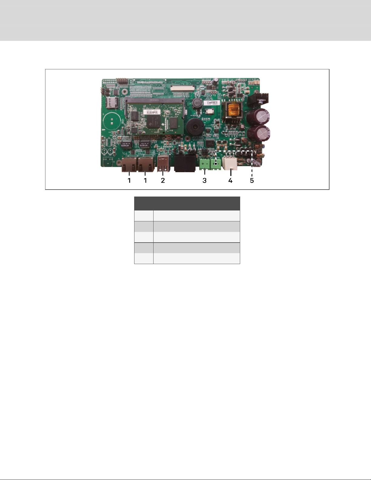
Figure 4.1 CMS Control-board connectors
ITEM DESCRIPTION
1 Ethernet port
2 USB ports
3 485 port for unit communication
4 24-VAC power input
5 485 port for BMS serial communication
4.2 Connecting the SRC andCMS ControlBoardswiththeModbusGateway
To communicate with a Liebert® SRC Mini-Split Cooling System, you must install a Modbus gateway that
connects the control board in the SRC evaporator/indoor unit and the iCOMCMS control board. Once
connected, the CMS control board can support up to 8 additional SRC units, by connecting gateways to
the units, and daisy-chaining the gateways together.
The Modbus gateway ships in its own box with the CMS kit. The Modbus gateway box includes the
following:
• Modbus gateway
• Black cable—to provide power and communication between the SRC board and the gateway.
• “Installation Manual V-Net”—instruction sheet to describe the connection between the SRC
board and the gateway.
36
Vertiv™ | Liebert® iCOM CMS™ Intaller/User Guide
Page 37
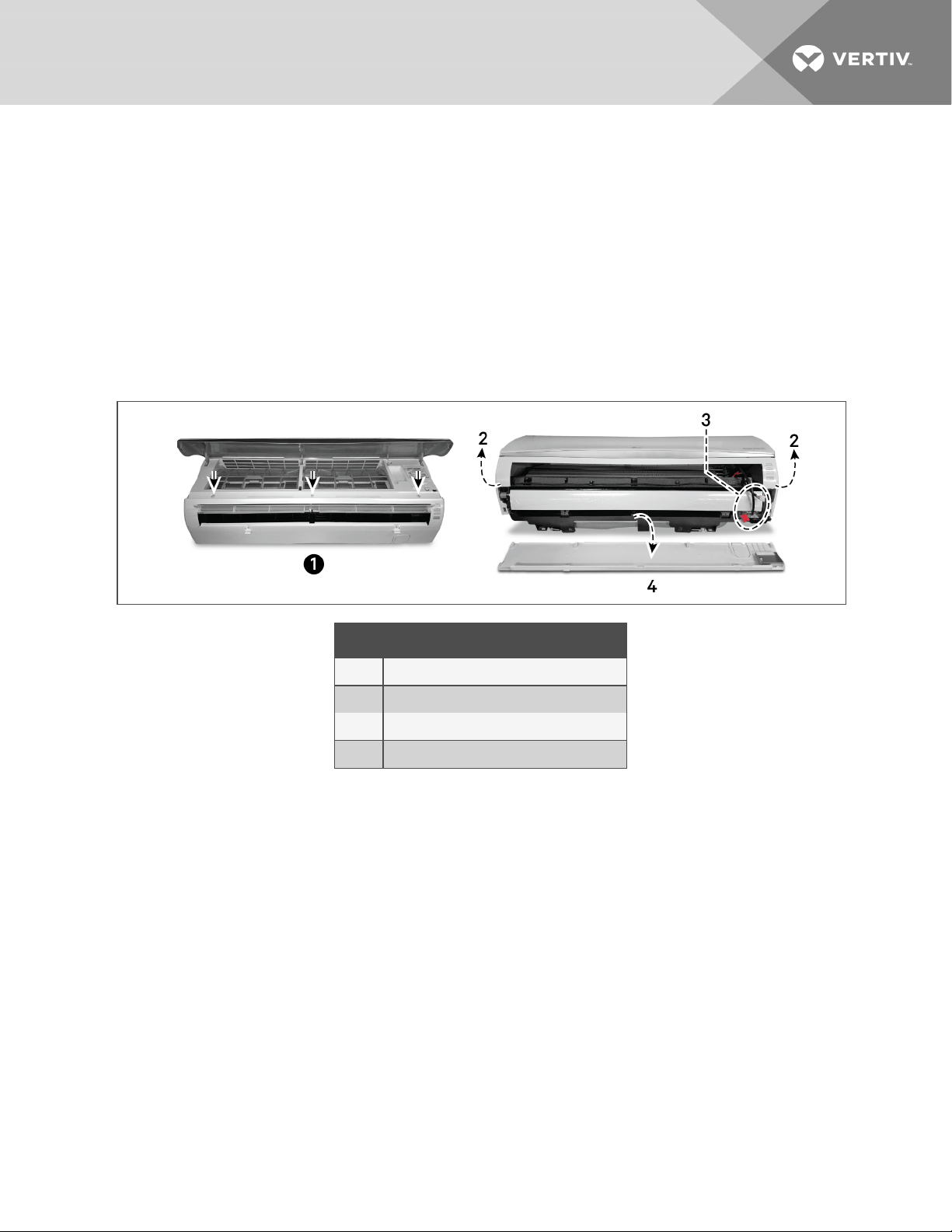
To connect the gateway to the SRC control board:
1. On the SRC evaporator/indoor unit, remove the shell to access the electrical section in the
right-hand side:
• Lift the top door, exposing the filter section, the door to the electric box, and the screws
that fasten the shell.
• Remove the screws shown in Figure 4.2 below.
• Carefully lift the top section slightly, locate the wiring to the LEDs on the front-right of the
unit, and disconnect the cable connectors to the LEDs.
• Remove the top shell, then the bottom shell sections.
Figure 4.2 Removing SRC shell
ITEM DESCRIPTION
1 Top door lifted. Fastening screws exposed.
2 Lift top section.
3 LED wiring to disconnect.
4 Pull down bottom section.
4 Installing and ConnectingiCOMCMS
37
Page 38
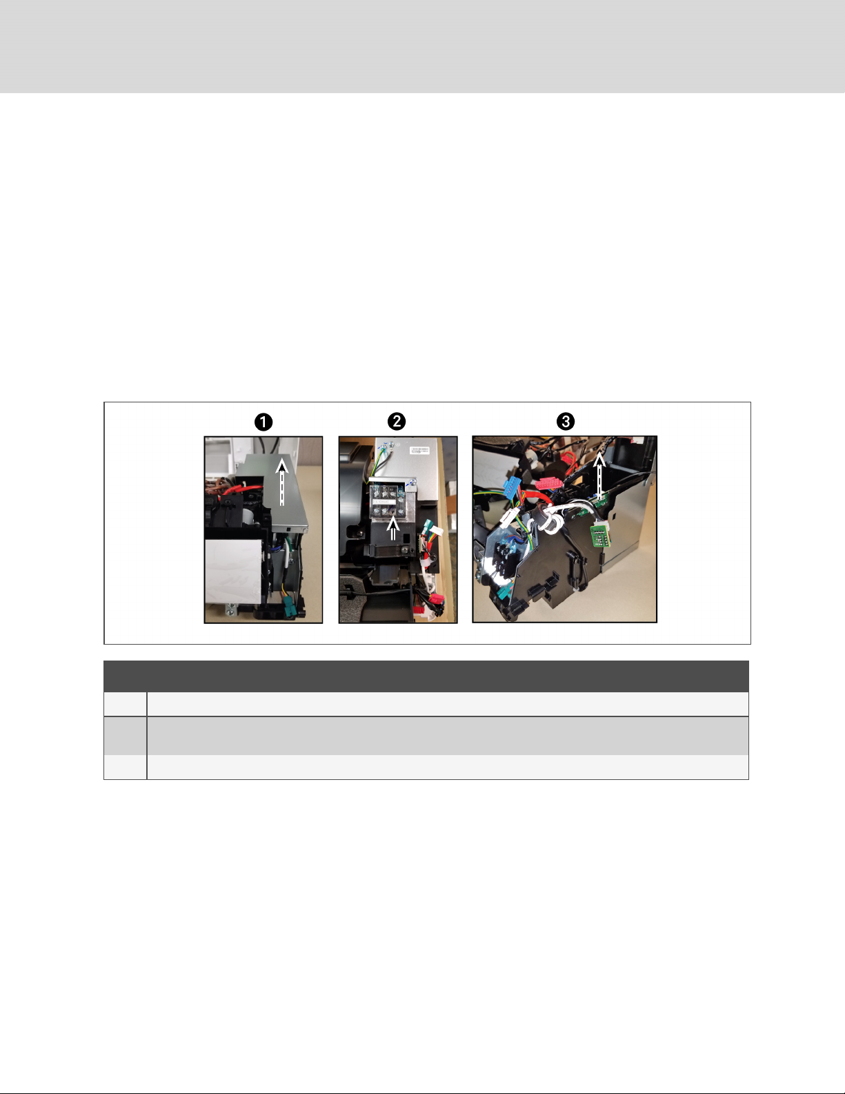
2. Depending on your unit model, locate the electrical panel on the right-hand side of the unit:
• SRC18 models: Lift the panel covering the control board on the right-hand side of the
unit, shown Figure 4.3 below.
• SRC24 and SRC36 models: Remove the terminal strip before attempting to lift the panel
by removing the single screw beneath the label on the terminal strip, see Figure 4.3
below.
3. Referring to Figure 4.3 below, lift the control board straight up to access the CN-CC plug
connection.
NOTE: You do not need to fully unplug and remove the control board to make the connection, but
because there is very little space in the electrical section, you may remove some plug connections from
the board for easier access. The plug connections are color coded, so reconnecting to the original plug
is simple.
Figure 4.3 Accessing the SRC control board
ITEM DESCRIPTION
1 On SRC18: Lift panelcovering control board.
2
3 Lift control board straight up.
38
On SRC24 or SRC36: Remove the screw in the terminal strip, remove the terminal strip, then lift the panel covering control
board.
Vertiv™ | Liebert® iCOM CMS™ Intaller/User Guide
Page 39
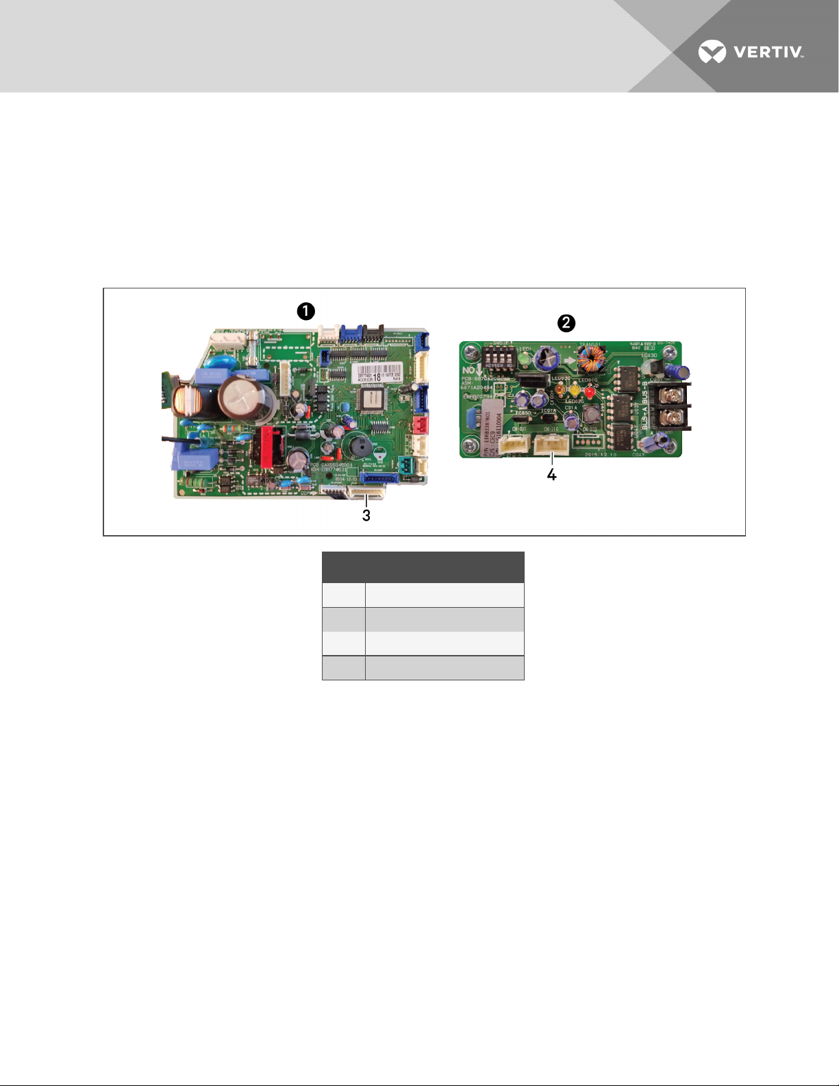
4. Connect the black cable to the appropriate plug connections as shown in Figure 4.4 below:
• On the SRC control board: CN-CC plug connector.
• On the Modbus gateway board: CN-OUT plug connector.
5. Re-connect any plugs removed for access and re-insert the control board.
6. Lower the electric panel, and the top shell, reconnect the LED wires, install the bottom shell
and secure with the 3 screws.
Figure 4.4 Connecting control board to Modbus
ITEM DESCRIPTION
1 SRC control board
2 Modbus gateway control board
3 CN-CC plug connector
4 CN-OUT plug connector
4.3 Setting up Communication withtheWeb-basedUserInterface
To register the thermal-management unit and configure communication settings, set-upaccess to the
control board.
NOTE: Only use the Google Chrome web browser to access the web UI.
1. Use a CAT5 Ethernet cable to connect a computer/laptop to an Ethernet port on the control
board (see Figure 4.1 on page36).
2. Configure the computer to communicate with the control board by changing its network
settings as follows:
• Set the computer’s static IP address to: 169.254.24.10
• Set the computer’s subnet mask to: 255.255.0.0
4 Installing and ConnectingiCOMCMS
39
Page 40

3. On the computer, open the Google Chrome web browser and enter the IP address of the
control board in the address bar: 169.254.24.7
The web UI opens.
NOTE: Before setting-up BMS protocols, you’ll need to change the IP address of the board from this
default address. See Connection Settings on page 25.
4. Log-in to the web UI using the advanced password: 2210.
You are ready to register the unit. See Registering with the Administration Portal
toAllowMobile-appUsers Access on page 41.
4.4 Set the Managing Mode to SRC
Set iCOMCMS to monitor Liebert® SRC units.
1. On the display, click SETTINGS, then iCOM-CMS Name in the settings list.
The iCOM-CMS panel displays.
2. Click Switch Mode.
The SWITCH MANAGING MODE dialog opens.
3. Click OK, then OK again.
The mode switches and the iCOM user-interface restarts. It may take a few minutes before you
can log-in again while the mode is switching.
4.5 Enable the Connected SRC Units
Up to 8 Modbus gateways can be daisy-chained to communicate with a single CMS control board. Each
connected SRC must be enabled in the Web UI.
To enable units:
1. On the display, click ADVANCED.
A list of units and their status displays.
2. Click the name of the unit to enable, then click Enable in the properties panel.
The CMS begins communicating and the Web UIdisplays current readings from the SRC unit.
40
Vertiv™ | Liebert® iCOM CMS™ Intaller/User Guide
Page 41

4.6 Registering with the Administration Portal toAllowMobile-appUsers Access
Thermal-management units must be registered to provide data to the cloud so that mobile-app users will
receive the notifications from the cooling unit.
Units are registered based on domain portion of the organization’s e-mail address. The domain is the part
after the “@” symbol and is typically the name of the organization, for example: @company.com.
NOTE: When registering the cooling unit, be sure to use an e-mail address with the correct domain of
the organization. If you register using an e-mail address with an incorrect domain, un-register and
contact the administrator for the correct address.
NOTE: The mobile app is available for download from the Apple Store or Google Play Store depending
on your mobile device. Look for “iCOMCMS.”
To register with the administration portal:
1. Obtain an e-mail address with valid domain from the iCOMCMS administrator who manages
mobile-app access for the organization.
2. On the web UI, click > Cloud Setup.
The CLOUD SETTINGS and REGISTER DEVICE FOR MOBILE APP ACCESS panels display.
3. In the register-device panel, type the provided e-mail address, then re-enter the e-mail address
and clickRegister.
The device is registered with the iCOMCMS Administration Portal, and the organization
information displays in the register-device panel.
Device-registration fields
Admin Email
E-mail of the iCOMCMS device administrator.
Re-enter Email
E-mail of the iCOMCMS device administrator.
Serial Number
Serial number of the iCOMCMS device.
Registration Code
Code used to register the device with the Admin Portal.
4.7 Setting Up Network Communication
1. Use an Ethernet cable to an Ethernet port on the control board to the network (See Figure 4.1
on page36).
2. On the web UI, click > Connection Settings.
NOTE: For descriptions of the connection-settings panel, see Connection Settings on page 25.
4 Installing and ConnectingiCOMCMS
41
Page 42
3. Based on the information provided by the IT administrator, select the Mode used for IP-address
assignment:
• DHCP—automatically assigns the settings from the organization’s network.
• Static—requires that you enter a dedicated IP address, subnet mask, default gateway,
and DNS servers.
4. If Static mode is selected, enter the settings obtained from the IT administrator:
• IP address
• Subnet mask
• Gateway
• DNS servers
5. Click Save.
4.8 Setting Up BMS serial communication
NOTE: The protocol willnot work with the control board’s default IP address: 169.254.24.7. Make sure a
Static or DCHP address is set. See Connection Settings on page 25.
NOTE: For external monitoring via Ethernet connection, see Modbus TCP Set Up on page 23.
To set up the BMS connection:
1. Depending on the type of BMS serial connection:
• For Modbus RTU, connect a serial cable to the correct 485 port on the control board (see
Figure 4.1 on page36).
2. On the web UI, click > BMS Setup, select the serial option to use, and configure the
communication settings:
• For Modbus serial communication, see Modbus RTU Set Up on page 23.
42
Vertiv™ | Liebert® iCOM CMS™ Intaller/User Guide
Page 43

APPENDICES
Appendix A: Technical Support and Contacts
A.1 Technical Support/Service in the United States
Vertiv Corporation
24x7 dispatch of technicians for all products.
1-800-543-2378
Liebert Thermal Management Products
1-800-543-2778
Liebert Channel Products
1-800-222-5877
Liebert AC and DC Power Products
1-800-543-2378
A.2 Locations
United States
Vertiv Headquarters
1050 Dearborn Drive
Columbus, OH, 43085, USA
Europe
Via Leonardo Da Vinci 8 Zona Industriale Tognana
35028 Piove Di Sacco (PD) Italy
Asia
7/F, Dah Sing Financial Centre
3108 Gloucester Road, Wanchai
A.3 How are we doing?
If you have comments or suggestions about iCOMCMS, please let us know. Send an email to
[email protected]. We look forward to hearing from you.
43
Page 44

This page intentionally left blank
44
Vertiv™ | Liebert® iCOM CMS™ Intaller/User Guide
Page 45

Vertiv™ | Liebert® iCOM CMS™ Intaller/User Guide
Page 46

VertivCo.com | Vertiv Headquarters, 1050 Dearborn Drive, Columbus, OH, 43085, USA
© 2018 VertivCo. All rights reserved. Vertiv and the Vertivlogo are trademarks or registered trademarks of VertivCo. All other names andlogos referred to
are trade names, trademarks or registered trademarks of their respective owners. While every precaution has been taken to ensure accuracy and
completeness herein, VertivCo. assumes no responsibility, and disclaims allliability, for damages resulting from use of this information or for any errors or
omissions. Specifications are subject to c hange without notice.
SL-18860_REV2/590-1564-501C
 Loading...