

Vertiv Liebert GXT5-750LVRT2UXL, Liebert GXT5-2000LVRT2UXL, Liebert GXT5-3000LVRT2UXL, Liebert GXT5-1500LVRT2UXL, Liebert GXT5-1000LVRT2UXL Installer/user Manual
...
Liebert®
GXT5™ UPS
120 V Input, 120 V Output
LV
Installer/User Guide

The information contained in this document is subject to change
without notice and may not be suitable for all applications.
While every precaution has been taken to ensure the accuracy
and completeness of this document, Vertiv assumes no
responsibility and disclaims all liability for damages resulting
from use of this information or for any errors or omissions. Refer
to other local practices or building codes as applicable for the
correct methods, tools, and materials to be used in performing
procedures not specifically described in this document.
The products covered by this instruction manual are
manufactured and/or sold by Vertiv. This document is the
property of Vertiv and contains confidential and proprietary
information owned by Vertiv. Any copying, use or disclosure of
it without the written permission of Vertiv is strictly prohibited.
Names of companies and products are trademarks or registered
trademarks of the respective companies. Any questions
regarding usage of trademark names should be directed to the
original manufacturer.
Technical Support Site
If you encounter any installation or operational issues with your product, check the pertinent section of this
manual to see if the issue can be resolved by following outlined procedures.
Visit https://www.vertiv.com/en-us/support/ for additional assistance.

Table of Contents
Important Safety Information ������������������������������������������������������������������������������������������������������������������������������������������������������ 1
Chapter 1: GXT5 Description ����������������������������������������������������������������������������������������������������������������������������������������������������������������� 3
1�1� UPS Features and Available Models ��������������������������������������������������������������������������������������������������������������������������������������������������������������������������3
1�2� Front Panels ������������������������������������������������������������������������������������������������������������������������������������������������������������������������������������������������������������������������������������������������������4
1�3� Rear Panels �������������������������������������������������������������������������������������������������������������������������������������������������������������������������������������������������������������������������������������������������������4
1�4� Battery Cabinet����������������������������������������������������������������������������������������������������������������������������������������������������������������������������������������������������������������������������7
1�5� Major Internal Components and Operating Principle �����������������������������������������������������������������������������������������������������������������������������7
1�6� UPS States and Operating Modes ����������������������������������������������������������������������������������������������������������������������������������������������������������������������������� 9
1�6�1� Normal Mode ������������������������������������������������������������������������������������������������������������������������������������������������������������������������������������������������������������������� 9
1�6�2� Bypass Mode �������������������������������������������������������������������������������������������������������������������������������������������������������������������������������������������������������������������� 9
1�6�3� Battery Mode ������������������������������������������������������������������������������������������������������������������������������������������������������������������������������������������������������������������ 9
1�6�4� Frequency Converter Mode ���������������������������������������������������������������������������������������������������������������������������������������������������������������������������� 9
1�6�5� ECO Mode ����������������������������������������������������������������������������������������������������������������������������������������������������������������������������������������������������������������������� 10
Chapter 2: Installation ������������������������������������������������������������������������������������������������������������������������������������������������������������������������ 11
2�1� Unpacking and Inspection ������������������������������������������������������������������������������������������������������������������������������������������������������������������������������������������������ 11
2�2� Pre-installation Preparation ������������������������������������������������������������������������������������������������������������������������������������������������������������������������������������������� 11
2�2�1� Installation Clearances ����������������������������������������������������������������������������������������������������������������������������������������������������������������������������������������� 11
2�3� Installing the UPS ����������������������������������������������������������������������������������������������������������������������������������������������������������������������������������������������������������������������������������������������������12
2�3�1� Tower Installation ����������������������������������������������������������������������������������������������������������������������������������������������������������������������������������������������������� 12
2�3�2� Rack Installation ������������������������������������������������������������������������������������������������������������������������������������������������������������������������������������������������������� 13
2�4� Installing External Battery Cabinets ���������������������������������������������������������������������������������������������������������������������������������������������������������������������� 13
2�5� Connecting AC Input Power ������������������������������������������������������������������������������������������������������������������������������������������������������������������������������������������ 15
2�6� Communication Connections ����������������������������������������������������������������������������������������������������������������������������������������������������������������������������������������������������������16
Vertiv | Liebert® GXT5™ | Installer/User Guide i

2�6�1� Connecting IntelliSlot Communication ����������������������������������������������������������������������������������������������������������������������������������������������� 16
2�6�2� Connecting to the Dry-contact Port ���������������������������������������������������������������������������������������������������������������������������������������������������������������������� 16
2�6�3� Connecting a Remote Emergency Power-o (REPO) Switch ��������������������������������������������������������������������������������������18
2�6�4� Connecting a USB Cable ���������������������������������������������������������������������������������������������������������������������������������������������������������������������������������19
2�6�5� Connecting CLI Communication Cables ������������������������������������������������������������������������������������������������������������������������������������������19
Chapter 3: Operating the UPS ��������������������������������������������������������������������������������������������������������������������������������������������������21
3�1� Silencing the Audible Alarm ������������������������������������������������������������������������������������������������������������������������������������������������������������������������������������������� 21
3�2� Starting-up the UPS �����������������������������������������������������������������������������������������������������������������������������������������������������������������������������������������������������������������������������������������21
3�3� Transferring to Battery Mode ������������������������������������������������������������������������������������������������������������������������������������������������������������������������������������22
3�4� Transferring from Normal to Bypass Mode �������������������������������������������������������������������������������������������������������������������������������������������������22
3�5� Transferring from Bypass to Normal Mode ��������������������������������������������������������������������������������������������������������������������������������������������������22
3�6� Shutting-down the UPS Completely ���������������������������������������������������������������������������������������������������������������������������������������������������������������������23
3�7� Remote Emergency Power-o (REPO) ������������������������������������������������������������������������������������������������������������������������������������������������������������23
Chapter 4: Operation and Display Panel ����������������������������������������������������������������������������������������������������������������������� 25
4�1� LED Indicators ���������������������������������������������������������������������������������������������������������������������������������������������������������������������������������������������������������������������������27
4�2� LCD Menu and Screens ���������������������������������������������������������������������������������������������������������������������������������������������������������������������������������������������������27
4�2�1� Start-up and Flow Screens ������������������������������������������������������������������������������������������������������������������������������������������������������������������������������27
4�2�2� Main Menu ������������������������������������������������������������������������������������������������������������������������������������������������������������������������������������������������������������������� 28
4�2�3� Status Screen ������������������������������������������������������������������������������������������������������������������������������������������������������������������������������������������������������������� 29
4�2�4� Settings Submenu �������������������������������������������������������������������������������������������������������������������������������������������������������������������������������������������������32
4�2�5� Control Screen ����������������������������������������������������������������������������������������������������������������������������������������������������������������������������������������������������������� 41
4�2�6� Log Screen �������������������������������������������������������������������������������������������������������������������������������������������������������������������������������������������������������������������42
4�2�7� About Screen �������������������������������������������������������������������������������������������������������������������������������������������������������������������������������������������������������������� 45
4�3� Editing Display and Operation Settings ������������������������������������������������������������������������������������������������������������������������������������������������������������������������� 47
4�3�1� Settings Prompts ����������������������������������������������������������������������������������������������������������������������������������������������������������������������������������������������������� 47
Vertiv | Liebert® GXT5™ | Installer/User Guideii

4�3�2� Changing the Password �����������������������������������������������������������������������������������������������������������������������������������������������������������������������������������������������������������48
4�3�3� Selecting the Display Language ��������������������������������������������������������������������������������������������������������������������������������������������������������������� 48
4�3�4� Setting the Date and Time ����������������������������������������������������������������������������������������������������������������������������������������������������������������������������49
Chapter 5: Maintenance ������������������������������������������������������������������������������������������������������������������������������������������������������������������ 51
5�1� Replacing Batteries ��������������������������������������������������������������������������������������������������������������������������������������������������������������������������������������������������������������� 51
5�2� Charging Batteries �������������������������������������������������������������������������������������������������������������������������������������������������������������������������������������������������������������� 53
5�3� Checking UPS Operation ����������������������������������������������������������������������������������������������������������������������������������������������������������������������������������������������54
5�4� Cleaning the UPS ������������������������������������������������������������������������������������������������������������������������������������������������������������������������������������������������������������������ 54
5�5� Firmware Updates ����������������������������������������������������������������������������������������������������������������������������������������������������������������������������������������������������������������54
5�5�1� Updating Firmware with RDU101 Card Connection ��������������������������������������������������������������������������������������������������������������� 55
5�6� Updating DSP Firmware via RDU101 �������������������������������������������������������������������������������������������������������������������������������������������������������������������57
5�7� Updating Firmware with a CLI Connection �������������������������������������������������������������������������������������������������������������������������������������������������� 59
Chapter 6: Troubleshooting ������������������������������������������������������������������������������������������������������������������������������������������������������� 63
6�1� Symptoms that Require Troubleshooting ������������������������������������������������������������������������������������������������������������������������������������������������������������������ 63
6�2� Audible Alarm (Buzzer) ������������������������������������������������������������������������������������������������������������������������������������������������������������������������������������������������������������������63
6�2�1� Faults �����������������������������������������������������������������������������������������������������������������������������������������������������������������������������������������������������������������������������������64
6�3� Troubleshooting UPS Issues ������������������������������������������������������������������������������������������������������������������������������������������������������������������������������������� 65
Chapter 7: Specifications ��������������������������������������������������������������������������������������������������������������������������������������������������������������67
7�1� Battery Run Times �����������������������������������������������������������������������������������������������������������������������������������������������������������������������������������������������������������������70
Appendix I: Open Source Software Legal Notices ��������������������������������������������������������������������������������������������73
Appendix II: Technical Support ���������������������������������������������������������������������������������������������������������������������������������������������� 75
Vertiv | Liebert® GXT5™ | Installer/User Guide iii

Important Safety Information
IMPORTANT! This manual contains important safety instructions that must be followed during the installation
and maintenance of the UPS and batteries. Read this manual thoroughly and the safety and regulatory
information, available at https://www.vertiv.com/ComplianceRegulatoryInfo, before attempting to install,
connect to supply, or operate this UPS.
Vertiv | Liebert® GXT5™ | Installer/User Guide 1

This page is intentionally left blank�
Important Safety Information2

Chapter 1: GXT5 Description
The Liebert® GXT5 is a compact, online uninterruptible power system (UPS) that continuously conditions and
regulates its output voltage� The Liebert® GXT5 supplies microcomputers and other sensitive equipment with
clean sine-wave input power�
Upon generation, AC power is clean and stable� However, during transmission and distribution it is subject to
voltage sags, spikes, and complete failure that may interrupt computer operations, cause data loss, and damage
equipment�
The Liebert® GXT5 protects equipment from these disturbances� The Liebert® GXT5 continuously charges its
batteries from the mains, enabling it to supply power to connected loads, even when the mains fail�
1.1. UPS Features and Available Models
The GXT5 includes the following features� Table 1-1 below, lists the available models and power ratings�
• Enhanced load capacity with an output power factor of 1�
• Input power factor greater than 0�99�
• Optional tower or rack installation to meet varying installation requirements�
• Adapts to areas with unstable power-mains supply via high-frequency double-conversion topology structure,
with high input-power factor, wide input-voltage range, and output immune to grid interference�
• Programmable terminals protect key devices when load is heavy�
• Operation and display panel with model-specific color LCD oers simple configuration and control of the UPS�
• ECO power-supply mode and smart-sleep mode help you save the maximum amount of energy�
Table 1-1 UPS Models and Power Ratings
MODEL NUMBER NOMINAL POWER RATING @ 120 V INPUT
GXT5-500LVRT2UXL 500 VA/500 W
GXT5-750LVRT2UXL 750 VA/750 W
GXT5-1000LVRT2UXL 1000 VA/1000 W
GXT5-1500LVRT2UXL 1500 VA/1350 W
GXT5-2000LVRT2UXL 2000 VA/1800 W
GXT5-3000LVRT2UXL 3000 VA/2700 W
Vertiv | Liebert® GXT5™ | Installer/User Guide 3
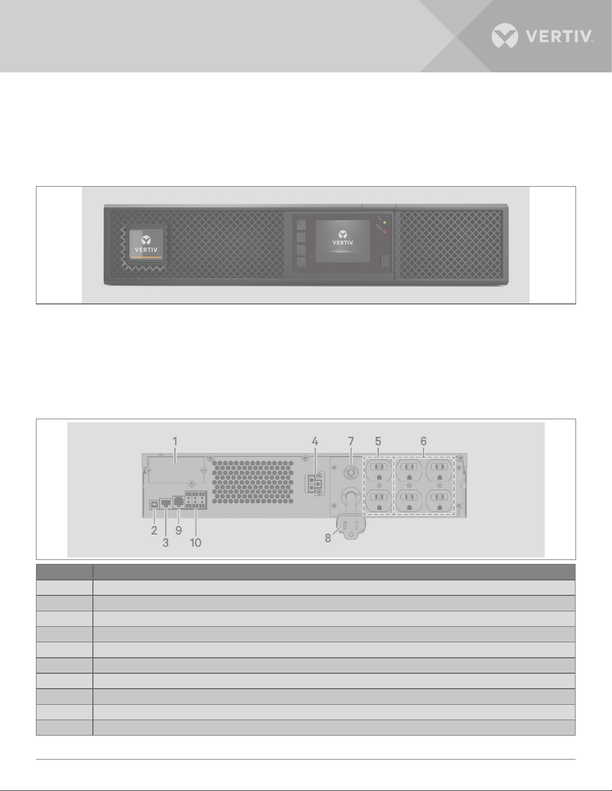
1.2. Front Panels
The various GXT5 models have the same general appearance, with the main dierence being the receptacle
types on the rear panel�
Figure 1-1 Front View
1.3. Rear Panels
The following figures detail the rear-panel features for each GXT5 model�
Figure 1-2 GXT5-500/750/1000/1500LVRT2UXL Rear Panel
ITEM DESCRIPTION
1 Liebert® IntelliSlot™ port
2 USB port
3 Un-used
4 External-battery connector
5 Non-programmable output receptacles, NEMA 5-15R
6 Programmable output receptacles, NEMA 5-15R
7 Input circuit breaker
8 Input-power plug and cable, NEMA 5-15P
9 R232 port, RJ-45/RJ-11 connection
10 Terminal-block communication connectors
GXT5 Description4
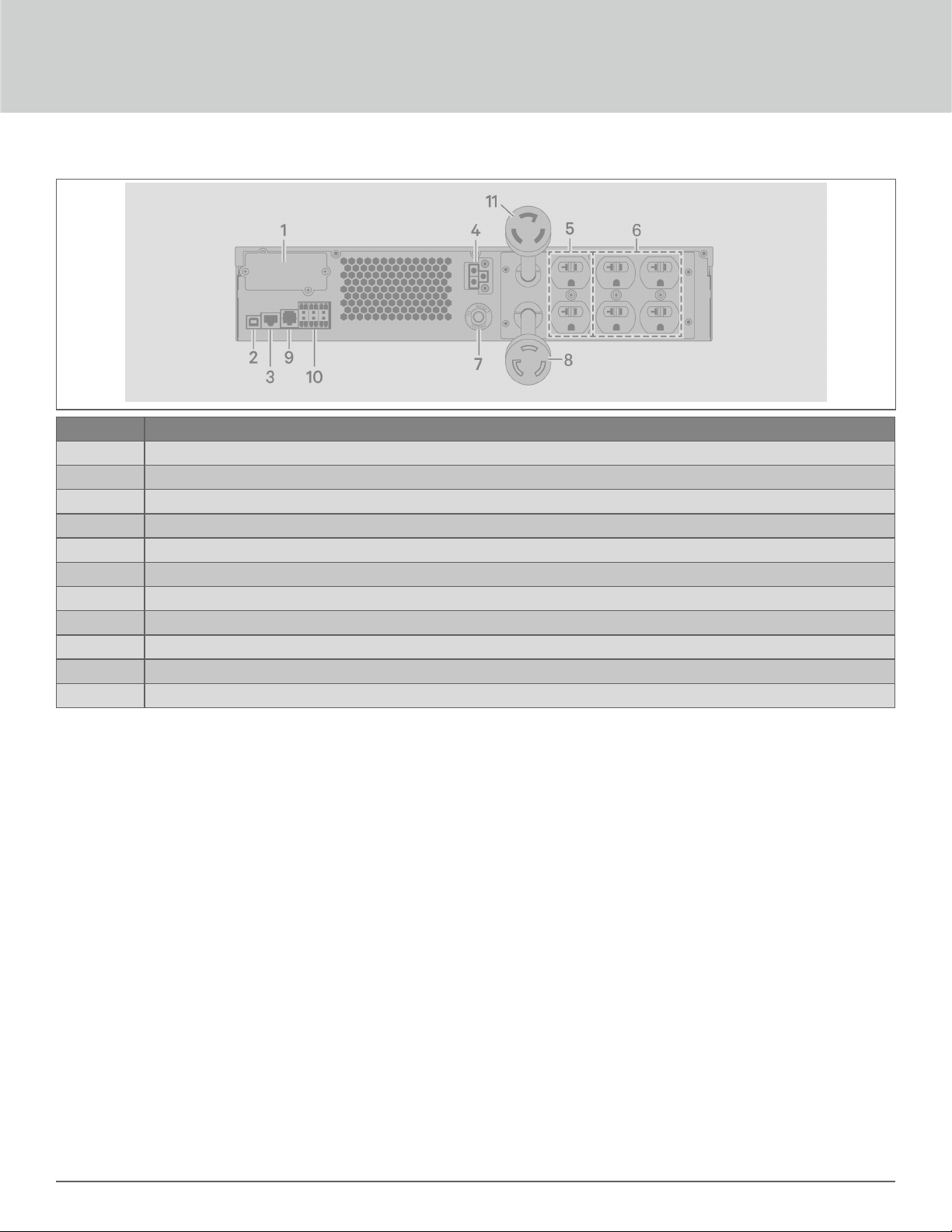
Figure 1-3 GXT5-2000LVRT2UXL Rear Panel
ITEM DESCRIPTION
1 Liebert® IntelliSlot™ port
2 USB port
3 Un-used
4 External-battery connector
5 Non-programmable output receptacles, NEMA 5-20R
6 Programmable output receptacles, NEMA 5-20R
7 Input circuit breaker
8 Input-power plug and cable, NEMA L5-20P
9 R232 port, RJ-45/RJ-11 connection
10 Terminal-block communication connectors
11 Output-power plug and cable, NEMA L5-20R
Vertiv | Liebert® GXT5™ | Installer/User Guide 5

Figure 1-4 GXT5-3000LVRT2UXL Rear Panel
ITEM DESCRIPTION
1 Liebert® IntelliSlot™ port
2 USB port
3 Un-used
4 External-battery connector
5 Non-programmable output receptacles, NEMA 5-20R
6 Programmable output receptacles
7 Output circuit breakers
8 Input-power plug and cable, NEMA L5-30P
9 R232 port, RJ-45/RJ-11 connection
10 Terminal-block communication connectors
11 Output-power plug and cable, NEMA L5-30R
12 Input circuit breaker
13 Cooling fan
GXT5 Description6
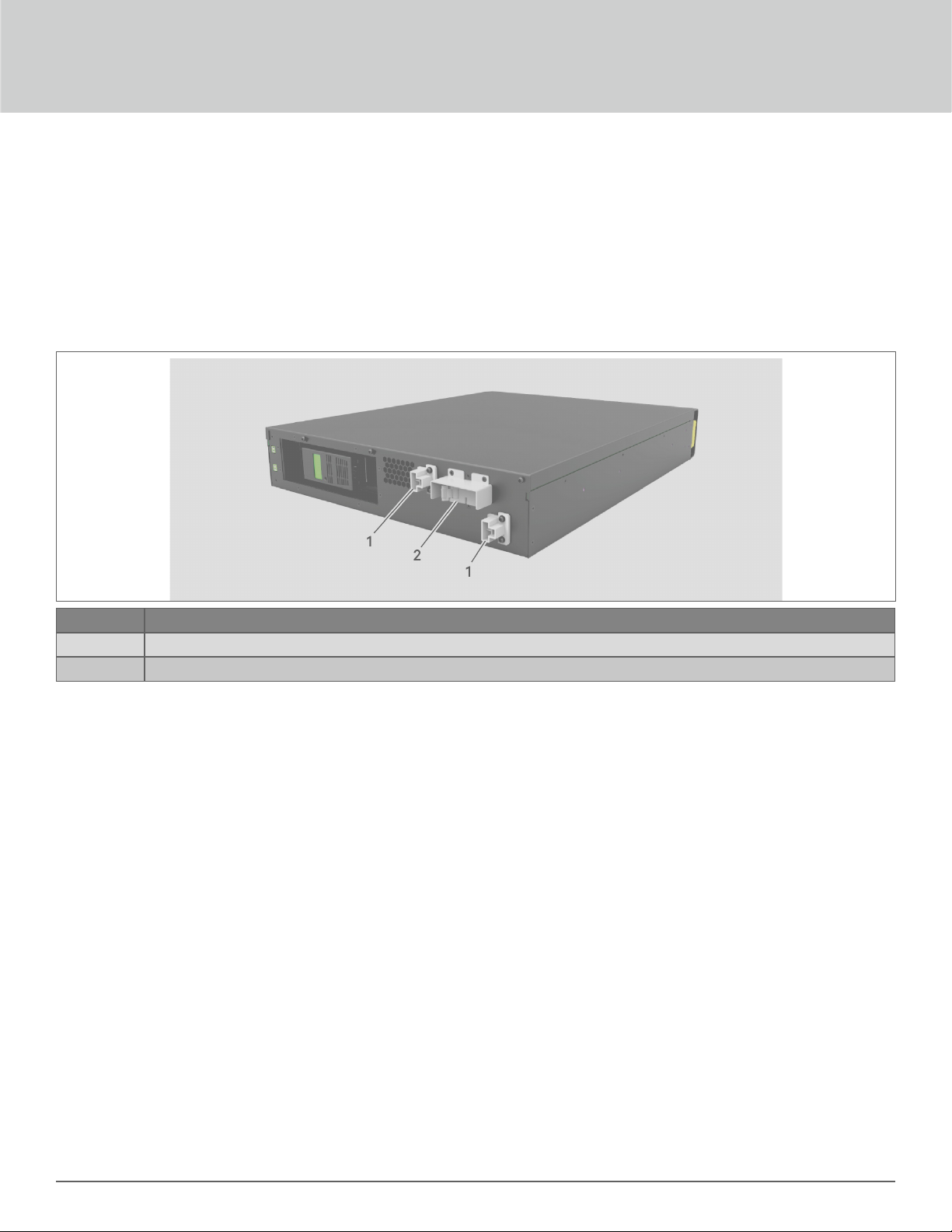
1.4. Battery Cabinet
Optional battery cabinets are available for the UPS, and include a single battery-connector cable� Up to 10 battery
cabinets may be connected in parallel to the UPS, and up to 6 can be auto-detected using EBC-detection� See
External Battery Cabinet Specifications on page 69, for the cabinet specifications� For approximate battery
run times with additional EBCs, see Battery Run Times on page 70� See Installing External Battery Cabinets
on page 13, to connect the cabinets�
Figure 1-5 Battery Cabinet
ITEM. DESCRIPTION
1 Battery connectors
2 Breaker
1.5. Major Internal Components and Operating Principle
Figure 1-6 on the next page, shows the UPS operating principle� Table 1-2 on the next page, describes the
function of the major components in the UPS�
NOTE: Figure 1-6 on the next page, is one example of basic operation�
Vertiv | Liebert® GXT5™ | Installer/User Guide 7
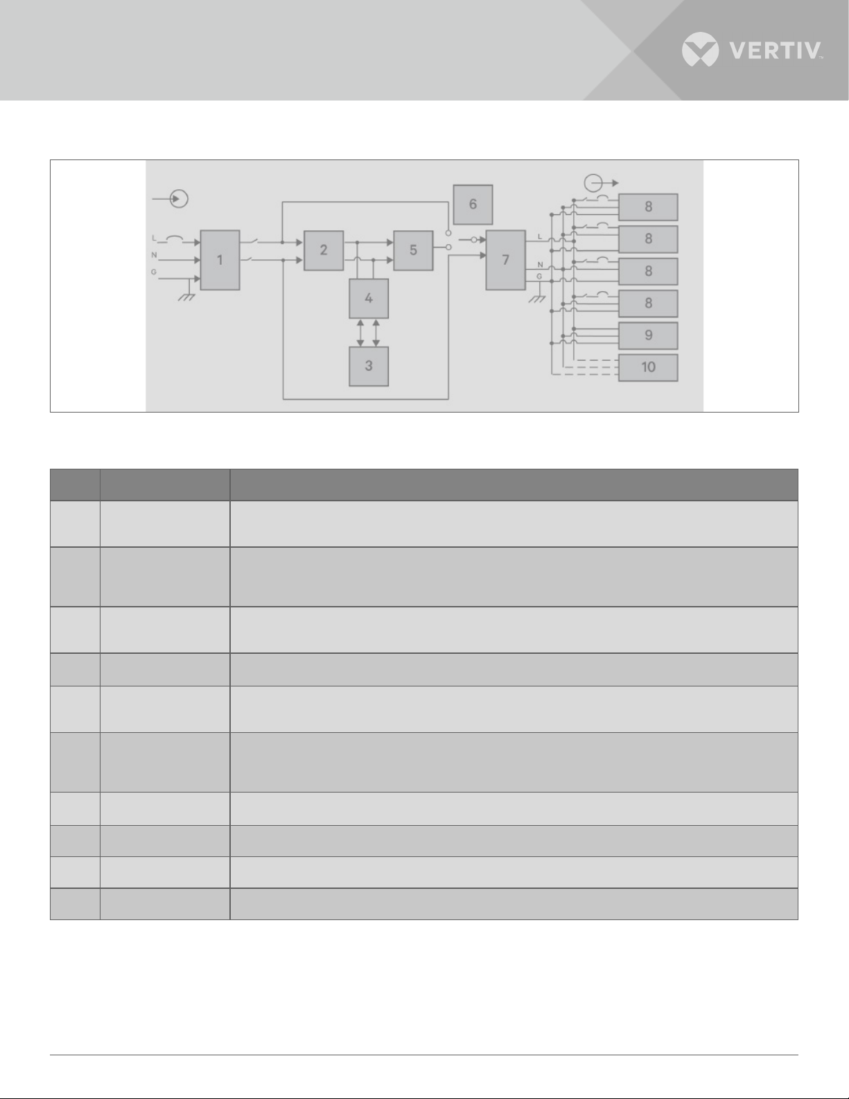
Figure 1-6 Basic Operating Principle Diagram
Table 1-2 Major Components
ITEM COMPONENT OPERATION/FUNCTION
1
2
3 Batteries
4 DC-to-DC Converter
5 Inverter
6
7 EMI/RFI Filters
8 Outlet group Programmable output receptacles�
9 Outlet group General output receptacles�
10 Outlet group General output receptacles on 2,000- and 3,000-VA models only�
Transient Voltage Surge
Suppression (TVSS)
and EMI/RFI Filters
Rectifier/Power Factor
Correction (PFC) Circuit
Dynamic Internal
Bypass
Provide surge protection� Filter electromagnetic interference (EMI) and radio frequency interference (RFI)� Minimize
surges or interference present in the utility power and protect devices connected on the same branch as the UPS�
In normal operation, converts utility AC power to regulated DC power for use by the inverter while ensuring that
the wave shape of the input current used by the UPS is near ideal� Extracting this sine-wave input current ensures
eicient use of utility power and reduces reflected harmonic distortion making cleaner power available to devices that
are not protected by the UPS�
Valve-regulated, non-spillable, lead-acid batteries�
NOTE: To maintain battery design life, operate the UPS in an ambient temperature of 59 °F to 77 °F (15 °C to 25
°C).
Raises the DC voltage from the battery to the optimum operating voltage for the inverter� This allows the inverter to
operate continuously at its optimum eiciency and voltage, thus increasing reliability�
In normal operation, inverts the DC output of the PFC circuit into precise, regulated sine-wave AC power� When utility
power fails, the inverter receives DC power from the DC-to-DC converter� In either operating mode, the UPS inverter
remains on-line, generating clean, precise, regulated AC-output power�
In the unlikely event of UPS failure such as overload or over-temperature, automatically transfers the connected load
to bypass�
To manually transfer the connected load from inverter to bypass, see Transferring from Normal to Bypass Mode on
page 26�
Filter electromagnetic interference (EMI) and radio frequency interference (RFI)� Minimize interference present in
the utility power and protect devices connected on the same branch as the UPS�
GXT5 Description8

1.6. UPS States and Operating Modes
NOTE: See LED Indicators on page 31, for description of the run-indicator and alarm-indicator LEDs
mentioned in this section.
1.6.1. Normal Mode
When utility power is normal, Normal mode employs the rectifier and inverter to provide voltage- and frequencystabilized power to the load� The charger charges the battery in normal mode� On the front- panel display, the runindicator (green) is ON, the alarm indicator is OFF, and the buzzer is silent�
1.6.2. Bypass Mode
Bypass mode supplies power to the load from the bypass source (utility power) if an overload or fault occurs during
normal operation� On the front-panel display, the run indicator (green) is ON, the alarm indicator (yellow) is ON, and
the buzzer beeps once each seconds� The LCD “Current” screen displays “On Bypass�”
NOTE: If utility power fails or if the utility voltage goes outside of the permissible range during bypass-mode
operation, the UPS shuts down and no output is supplied to the load.
1.6.3. Battery Mode
Battery mode supplies battery power to the load if utility power fails or if the utility voltage goes outside of the
permissible range� On the front-panel display, the run indicator (green) is ON, the alarm indicator (yellow) is ON,
and the buzzer beeps once each second� The LCD “Flow” screen displays “On Battery�”
NOTE: The batteries are fully-charged before shipment. However, transportation and storage inevitably
cause some loss of capacity. To ensure adequate back-up time, it is recommended to charge the batteries for
atleast 8 hours before first start-up.
NOTE: If utility power fails and the batteries are charged, you may cold-start the UPS in battery mode and use
battery power to extend system availability for a time.
NOTE: Powering-o the UPS when it is in battery mode results in loss of output power to the connected load.
1.6.4. Frequency Converter Mode
All models of the GXT5 are capable of frequency conversion� Frequency Conversion Mode can be selected using
the configuration program� Allowable frequency operating modes include:
• Auto Sensing - 50 Hz or 60 Hz – Bypass Enabled
• Auto Sensing - 50 Hz or 60 Hz – Bypass Disabled
• Frequency Converter - 50 Hz – Bypass Disabled
• Frequency Converter - 60Hz – Bypass Disabled
NOTE: The default for all models of the Liebert® GXT5 is “Auto Sensing - 50 Hz or 60 Hz – Bypass Enabled.”
Vertiv | Liebert® GXT5™ | Installer/User Guide 9

1.6.5. ECO Mode
The energy-saving ECO mode reduces power consumption by powering the load via bypass if the bypass voltage
is normal or by powering the load via the inverter when the bypass voltage is abnormal� You can use ECO mode to
power equipment that is not sensitive to power-grid quality to via bypass and reduce power consumption�
NOTE: During ECO mode, if a bypass-failure or abnormal-bypass-voltage notification appears when the output
is not overloaded, the UPS will transfer to Normal Mode. However, if a notification showing bypass failure
or abnormal bypass voltage appears when the output is overloaded, the UPS will shut down the bypass and
therefore the load will shut down.
GXT5 Description10

Chapter 2: Installation
Do not start the UPS until after the installation is finished�
WARNIN G! Ris k of electric shock
Can cause equipment damage, injury and death. Before beginning installation, verify that all external overcurrent
protection devices are open (O), and that they are locked-out and tagged appropriately to prevent activation
during the installation, verify with a voltmeter that power is O and wear appropriate, OSHA-approved
personal protective equipment (PPE) per NFPA 70E. Failure to comply can cause serious injury or death. Before
proceeding with installation, read all instructions. Follow all local codes
2.1. Unpacking and Inspection
Unpack the UPS and conduct the following checks:
• Inspect the UPS for shipping damage� If any shipping damage is found, report it to the carrier and your local
Vertiv representative immediately�
• Check the accessories included against the packing list� If there is any discrepancy, contact your local Vertiv
representative immediately�
.
CAUTION
The UPS is heavy (see Specifications on page 57, for the weight). Take proper precautions when lifting or
moving the unit.
2.2. Pre-installation Preparation
• Install the UPS indoors in a controlled environment, where it cannot be accidentally turned O� The installation
environment should meet the specifications listed in Specifications on page 57�
• Place the UPS in an area of unrestricted air-flow around the unit, away from water, flammable liquids, gases,
corrosives, and conductive contaminants� Avoid direct sunlight�
NOTE: Operating the UPS in temperatures above 77°F (25°C) reduces battery life.
2.2.1. Installation Clearances
Maintain at least 4 in� (100 mm) clearance in the front and rear of the UPS� Do not obstruct the air inlets on the
front panel and rear panel of the UPS� Blocking the air inlets reduces ventilation and heat dissipation, shortening
the service life of the unit�
Vertiv | Liebert® GXT5™ | Installer/User Guide 11
2.3. Installing the UPS
The UPS may be installed as a tower or in a rack, depending on available space and use considerations� Determine
the type of installation and follow the appropriate instructions� See Tower Installation or Rack Installation on next
page�
NOTE: When installing the UPS or making input and output connections, comply with all relevant safety
codes and standards.
2.3.1. Tower Installation
To install the UPS as a tower:
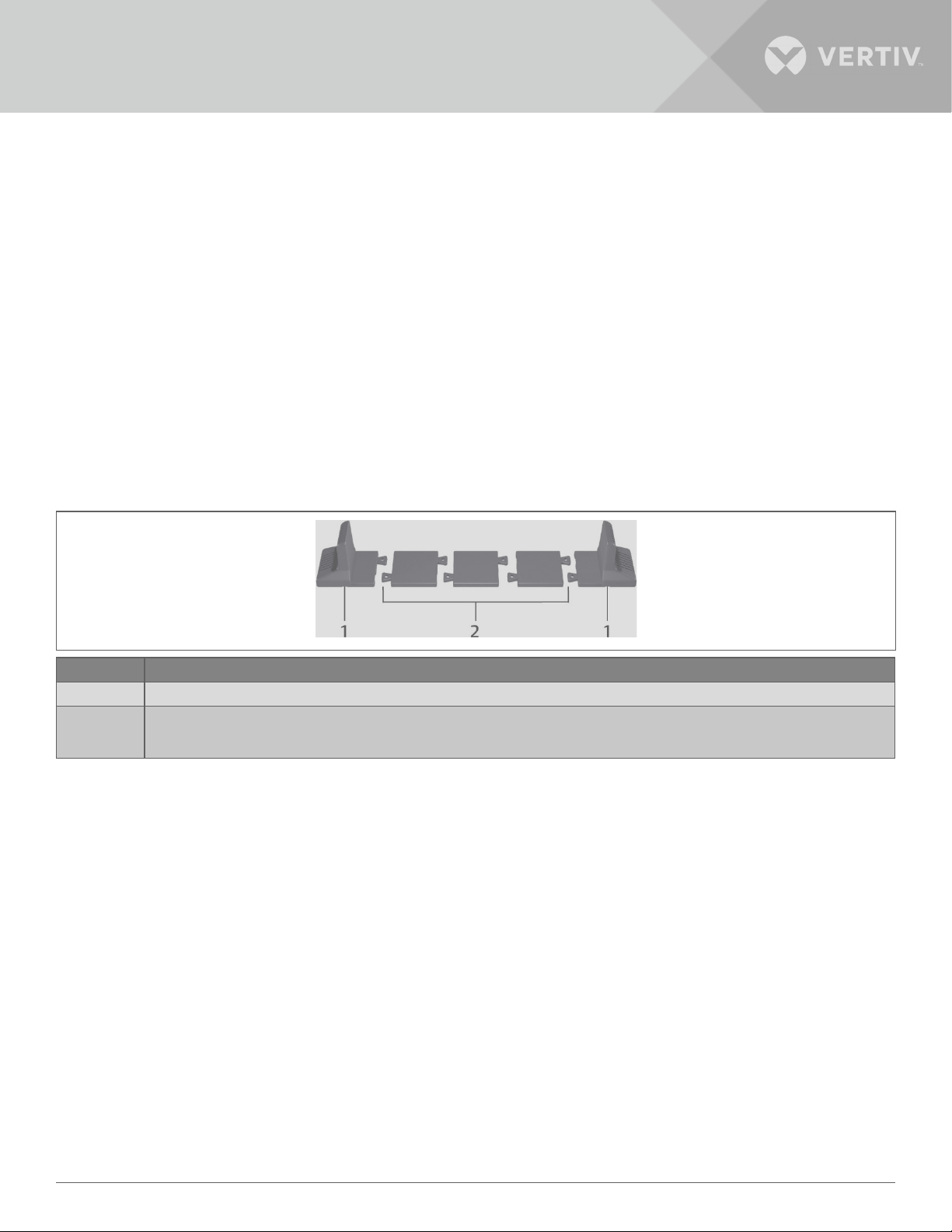
1� Take the support bases out of the accessories box�
Figure 2-1 Support bases
NO. DESCRIPTION
1 Support bases
2 Spacers with connectors
NOTE: Three spacers are shown here. However, the number of spacers varies depending on your UPS model and the number of
battery cabinets in your system.
2� If optional, Liebert® external battery cabinets will be connected, take out the spacers shipped with the battery
cabinet�
3� Connect the spacers and the support bases as shown in Figure 2-1 above� Each GXT5 requires 2 support bases,
one in the front and one in the rear�
4� Place the GXT5 and any battery cabinets on the 2 support bases�
Installation12

2.3.2. Rack Installation
When installed in a rack enclosure, the GXT5 UPS and external battery cabinets (EBC) must be supported by a shelf
or rack-mount rails� Because dierent rack-mount options install dierently, refer to the installation instructions
provided with the rack-mount kit�
CAUTION
The GXT5 is heavy. The UPS must be installed as near the bottom of a rack as possible. If placed too high, it can
make the rack top-heavy and prone to tipping over. For unit weights, see Specifications on page 57.
2.4. Installing External Battery Cabinets
Optional, external battery cabinets (EBC) may be connected in parallel to the UPS to provide additional battery
run time� For approximate battery run times with additional EBCs, see Battery Run Times on page 62� External
battery cabinets are placed on one side of the UPS in a tower configuration or stacked beneath the UPS in a rack
configuration� Up to 10 EBCs may be connected to the UPS, and up to 6 may be detected using EBC-detection�
WARNING! Risk of electric shock
Can cause injury or death. Disconnect all local and remote electric power supplies before working with the UPS.
Ensure that the unit is shut down and power has been disconnected before beginning any maintenance.
CAUTION
The external battery cabinet(s) are heavy, see Table 7-4 on page 61. Take proper precautions when lifting
them.
To install the EBC(s):
1� Inspect the EBC for freight damage� Report damage to the carrier and your local dealer or Vertiv representative�
2� For tower installation:
• An additional set of support-base extensions ships with each EBC�
• See the steps in Tower Installation, to connect the support extenders and install the bases�
- or –
3� For rack installation:
• Rack-mount hardware ships with the EBC�
• Refer to the instructions included with the rack-mount kit to install�
NOTE: Optional slide rails and securing hardware are sold separately. Please contact your Vertiv representative
for options and Vertiv Technical Support for assistance.
4� Verify that the EBC breaker is in the “O” position�
Vertiv | Liebert® GXT5™ | Installer/User Guide 13
5� Connect the supplied EBC cable(s) to the rear of the cabinet, then to the rear of the UPS, see Figure 2-2�
6� Turn the EBC breaker to the “On” position�
7� Verify the circuit breaker on the EBC is in the “On” position�
The additional back-up run time is enabled�
NOTE: If installing more than 6 EBCs, the user must adjust the number of EBCs manually in Settings > Battery
> External battery cabinet group No.
NOTE: When removing an EBC, turn o the circuit breaker on the rear of the cabinet before disconnecting the
cable.
NOTE: If shipping or storing the UPS for an extended time, disconnect the EBC(s) minimize stand-by current
drain on the batteries and help maintain design life.
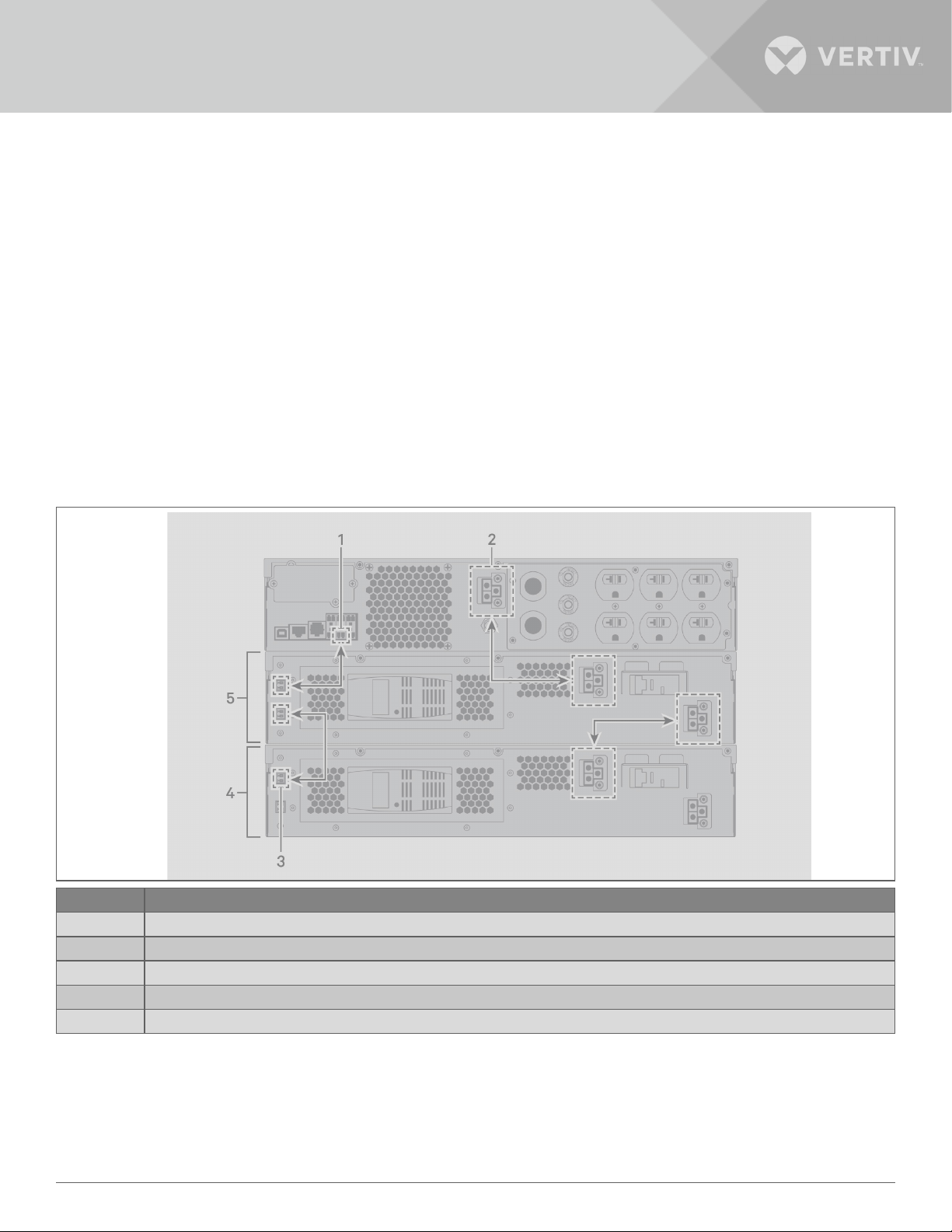
Figure 2-2 EBCs connected to the UPS
ITEM DESCRIPTION
1 EBC-detection port (See Table 2-2 on page 17, for details�)
2 EBC connector
3 EBC-detection port
4 External battery cabinet
5 External battery cabinet
Installation14

2.5. Connecting AC Input Power
Ensure that all the loads are turned O� Prepare an input power supply that is properly protected by a circuit breaker
in accordance with national and local electrical codes� The wall receptacle must be grounded� We recommend
installing an upstream circuit breaker of the same series as the input circuit breaker of the GXT5�
Table 2-1 below, lists the specifications of the input circuit breaker on the rear panel by UPS model�
Table 2-1 Input circuit breaker specifications
MODEL RATED CIRCUIT BREAKER
GXT5-500LVRT2UXL 12 A
GXT5-750LVRT2UXL 12 A
GXT5-1000LVRT2UXL 12 A
GXT5-1500LVRT2UXL 15 A
GXT5-2000LVRT2UXL 20 A
GXT5-3000LVRT2UXL 30 A
To connect AC-input power, plug the input plug of the UPS into the input-power connection�
NOTE: If the input plug will serve as the disconnecting device, the wall socket/outlet must be near the UPS and
must be easily accessible, per the National Electric Code/NFPA 70 requirements.
A. Connecting Loads
500-VA to 1500-VA models have six outlets:
• Two are not programmable (always On)�
• Four are controlled with programmed responses or an SNMP network�
2000-VA and 3000-VA models have seven outlets:
• Three are not programmable (always On)�
• Two groups are controlled with programmed responses or an SNMP network�
NOTE: When connecting load, verify that the equipment is plugged into the appropriate outlets if any of the
outlets will be controlled. Do not overload any output receptacle. Output cable length should not exceed 10
m (32.8 ft).
To connect equipment, plug equipment into the appropriate output receptacles on the rear of the UPS, see the
appropriate figure for your model in Rear Panels on page 4�
Vertiv | Liebert® GXT5™ | Installer/User Guide 15
2.6. Communication Connections
The UPS oers several communication interfaces and ports�
NOTE: We recommend that signal-cable lengths be less than 10 ft (3 m), and are kept away from power
cabling.
2.6.1. Connecting IntelliSlot Communication
The Liebert® IntelliSlot™ RDU101 provides SNMP monitoring of the UPS across the network and/or building
management system�
See the appropriate figure for your model in Rear Panels on page 4, for the location of the card port�
To install an IntelliSlot Card:
1� Remove the screws from the slot cover plate and remove the plate�
2� Insert the card into the slot, and secure with the screws that held the cover plate�
To make connections to the card, refer to the Installer/User Guide for the appropriate IntelliSlot card available at
www�vertiv�com�
2.6.2. Connecting to the Dry-contact Port
The UPS includes a dry-contact port� See the appropriate figure for your model in Rear Panels on page 4, for
the location of the port� Figure 2-3 below, shows the ports and Table 2-2 on the next page, describes each port�
The I/O dry contact port capacity is 125 Vac, 0�5 A; 30 Vdc, 1 A�
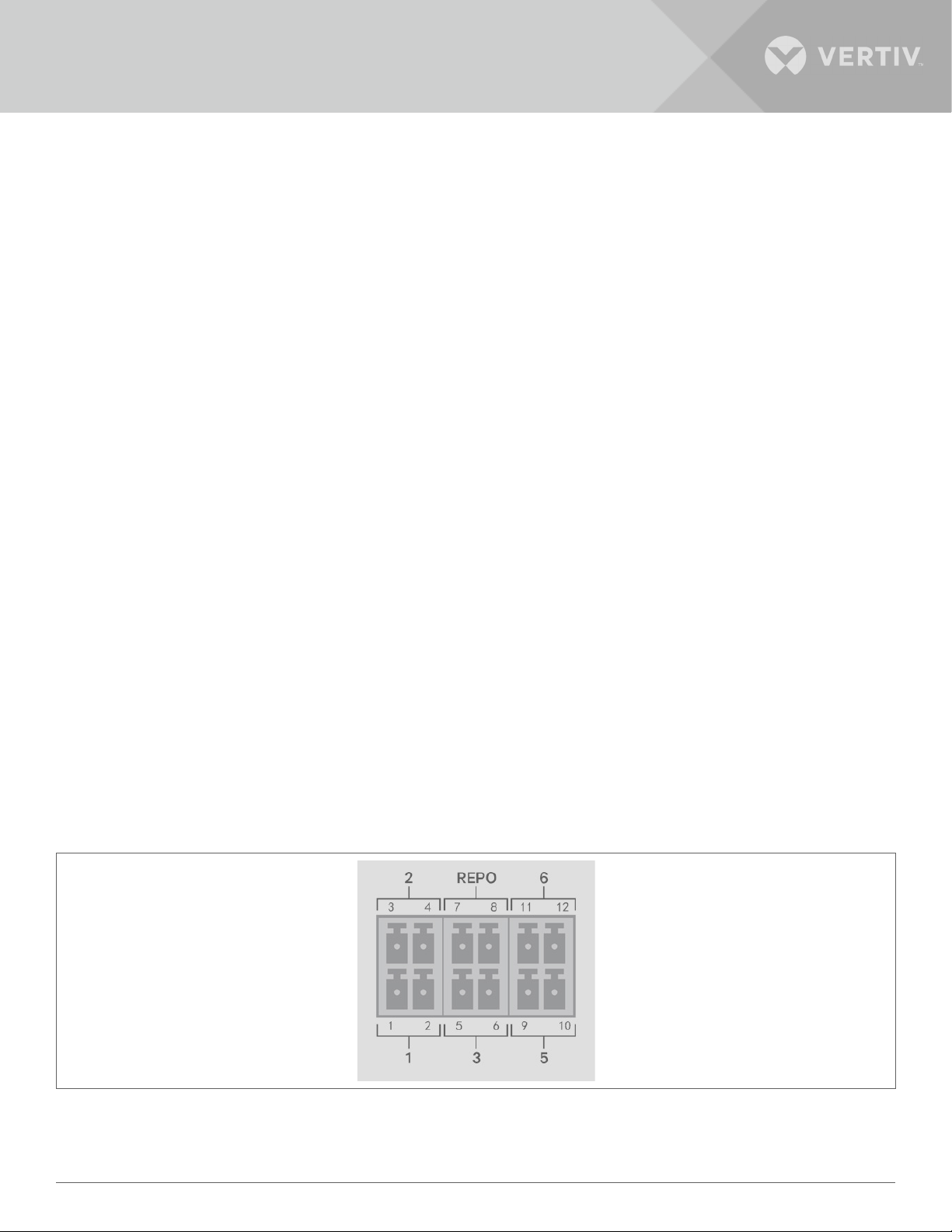
Figure 2-3 Dry-contact Port and Pin Layout
NOTE: Pins 7 and 8 are shorted before delivery.
Installation16

NOTE: The emergency power-o (EPO) action of the UPS closes the rectifier, inverter and static bypass,
but it cannot disconnect the UPS mains input inside. To completely disconnect the UPS, disconnect the
upstream input circuit breaker when generating the EPO. For details on REPO connection and operation, see
Connecting a Remote Emergency Power-o (REPO) Switch on the next page.
Table 2-2 Dry-contact Connection and Pin-out Descriptions
PORT
NO.
1
Input 1
2
Input 2
3 Battery
Detection
PORT
NAME
PIN
NO.
1 Remote Comms Shutdown 1
2 Signal Ground Signal Ground
3 Remote Comms Shutdown 2
4 Signal Ground Signal Ground
5 EBC Detection
6 EBC Detection
PIN NAME DESCRIPTION
User configurable dry-contact input that can be set to trigger the events below� The user
can also select the dry-contact as either NO or NC� (See System Parameter Options on
page 37) When NO, Pins 1 and 2 are shorted to trigger the event� When NC, Pins 1 and
2 are opened to trigger the event�
Options are:
• Disable (default)
• Battery mode shutdown - If the UPS is running on batteries and this input is triggered,
the UPS shuts down
• Any mode shutdown - If this input is triggered, the UPS shuts down regardless of current
operating mode
User configurable dry-contact input that can be set to trigger the events below� The user
can also select the dry-contact as either NO or NC� (See System Parameter Options on
page 37) When NO, Pins 3 and 4 are shorted to trigger the event� When NC, Pins 3 and
4 are opened to trigger the event�
Options are:
• Disable (default)
• Battery mode shutdown - If the UPS is running on batteries and this input is triggered,
the UPS shuts down
• Any mode shutdown - If this input is triggered, the UPS shuts down regardless of current
operating mode
Automatically detects number of external- battery cabinets when pins 5 and 6 are
connected to the detection port, see Installing External Battery Cabinets on page 13�
Automatically detects number of external- battery cabinets when pins 5 and 6 are
connected to the detection port, see Installing External Battery Cabinets on page 13�
7 +5V REPO power supply, 5-Vdc 100-mA
REPO REPO
Input
5 Output 5 9, 10 Remote Fault Alert 5
6 Output 6 11, 12 Remote Fault Alert 6
8 REPO Coil -NC
NC, activated when Pin 7 and Pin 8 is open
NOTE: For details on REPO connection and operation, see Connecting a Remote
Emergency Power-o (REPO) Switch.
User configurable dry-contact output that can be set to alert the user to the faults below�
The user can also select the dry-contact as either NO or NC� (See System Parameter
Options on page 37) When NO, Pins 9 and 10 are shorted when the fault occurs� When
NC, Pins 9 and 10 are opened when the fault occurs�
Options are:
• Low battery (default)
• On battery
• On bypass
• UPS fault
User configurable dry-contact output that can be set to alert the user to the faults
below� The user can also select the dry-contact as either NO or NC� (See System
Parameter Options on page 37) When NO, Pins 11 and 12 are shorted when the fault
occurs� When NC, Pins 11 and 12 are opened when the fault occurs�
Options are:
• Low battery
• On battery
• On bypass
• UPS fault (default)
Vertiv | Liebert® GXT5™ | Installer/User Guide 17

2.6.3. Connecting a Remote Emergency Power-o (REPO) Switch
The UPS includes an EPO connection in the dry-contact port� See the appropriate figure for your model in Rear
Panels on page 4, for the location of the port�
UPS ships with a REPO jumper installed, allowing the UPS to operate as a normally-closed switch system (fail-safe)�
Opening the circuit disables the UPS� To connect a REPO switch that opens the circuit to shut down the rectifier
and inverter and power-o the UPS, use a cable from the remote switch to plug into the REPO-port on the UPS�
In normal conditions, the REPO switch cannot cut o the UPS input power� When the REPO switch trips, the UPS
generates an alarm and immediately cuts-o output power� When the emergency condition is resolved, the UPS
will not return to normal operation until you reset the REPO switch and manually power- on the UPS�
To make the cable for the REPO connection:
Figure 2-4 below, shows the cable required to make the connection� We recommend using 18 AWG to 22 AWG (0�82
mm2 to 0�33 mm2) copper-core cable�
1� Remove the insulation from the end of two cables�
2� Insert the stripped end into the plug terminals 1 and 2 respectively, then press down the terminals� Make sure
that the cables are secure in the plug to prevent failure because of loose contact�
To connect a UPS to the REPO switch.
CAUTION
To maintain safety (SELV) barriers and electromagnetic compatibility, signal cables should be shielded and run
separately from power cables.
1� Connect one end of the cable to the remote switch, see Figure 2-4 below�
2� Remove the factory-installed jumper from pins 7 and 8 of the dry-contact port on the UPS�
3� Connect the plug to pins 7 and 8�
Figure 2-4 Cable/Plug for Connecting REPO switch to UPS REPO port
ITEM DESCRIPTION
1 Terminal 1
2 Terminal 2
3 Plug (connects to REPO port on UPS)
4 REPO switch
Installation18

2.6.4. Connecting a USB Cable
The UPS includes a USB connector� See the appropriate figure for your model in Rear Panels on page 4, for the
location of the port�
The standard, B-type USB port connects the UPS to a network server or other computer system� The USB port
supports HID/CDC protocol� The CDC protocol is reserved for service software� To use the HID protocol for
monitoring, get Power Assist from www�vertiv�com�
2.6.5. Connecting CLI Communication Cables
The UPS supports the Vertiv command-line interface for operation with Vertiv ACS and other third-party monitoring
protocols� The RJ-45 port (labeled “R232”) is used for CLI connection� See the appropriate figure for your model in Rear
Panels on page 5, for the location of the port� The pin-out, described in below table is consistent with the ACS pin-out�
ITEM DESCRIPTION
1 NC
2 NC
3 TXD (out)
4 GND
5 NC
6 RXD (in)
7 NC
8 NC
Vertiv | Liebert® GXT5™ | Installer/User Guide 19

This page is intentionally left blank�
Installation20
 Loading...