

Vertiv LIEBERT GXT5-500LVRT2UXL, LIEBERT GXT5-2000LVRT2UXL, LIEBERT GXT5-750LVRT2UXL, LIEBERT GXT5-1500LVRT2UXL, LIEBERT GXT5-3000LVRT2UXL Quick Installation Manual
...
LIEBERT® GXT5™ UPS
120‑V500–3,000VA
Quick Installation Guide
I M P O RTANT: Before installing,
connecting to supply or operating
your Liebert GXT5 UPS, please
review the Safety and Regulatory
Statements sheet. For detailed
installation, operating, maintenance
and troubleshooting info
rmation refer to the GXT5 User
Guide for your model available at
www.VertivCo.com.
INSTALLATIO N
1. Inspecting the UPS
Inspect the UPS for any signs of
obvious damage. If damage is
visible, do not proceed and call
our warranty support line for
assistance at 1-800-222-5877
menu option 3, or email at
microups.warranty@vertivco.com.
2. Choosing a location
Install the UPS in a temperaturecontrolled environment that is
free of corrosive and conductive
contaminants. Avoid locations
near heat or water sources and
exposed to direct sunlight.
For proper ventilation, leave four
inches clearance on all sides of
the UPS.
The input outlet should be
nearby and easily accessible.
3. Installing the UPS
The UPS and optional External
Battery Cabinets may be
installed in either a tower or rack
conguration. For tower
installation, assemble and attach
the tower support stands. For
rack installation, attach the
brackets to the UPS, install the
rail kit in the rack if needed, and
install the UPS in the rack.
NOTE :
computer room as dened in the
standard for the protection of
electronic computer/data
processing equipment of ANSI/
NFPA 75.
This UPS is not for use in a
MODEL DESIGN CONFIGURATIONS
GXT5‑500/750/1000/1500LVRT2UXL
2 9
GXT5‑2000LVRT2UXL
2 9
GXT5‑3000LVRT2UXL
2 9
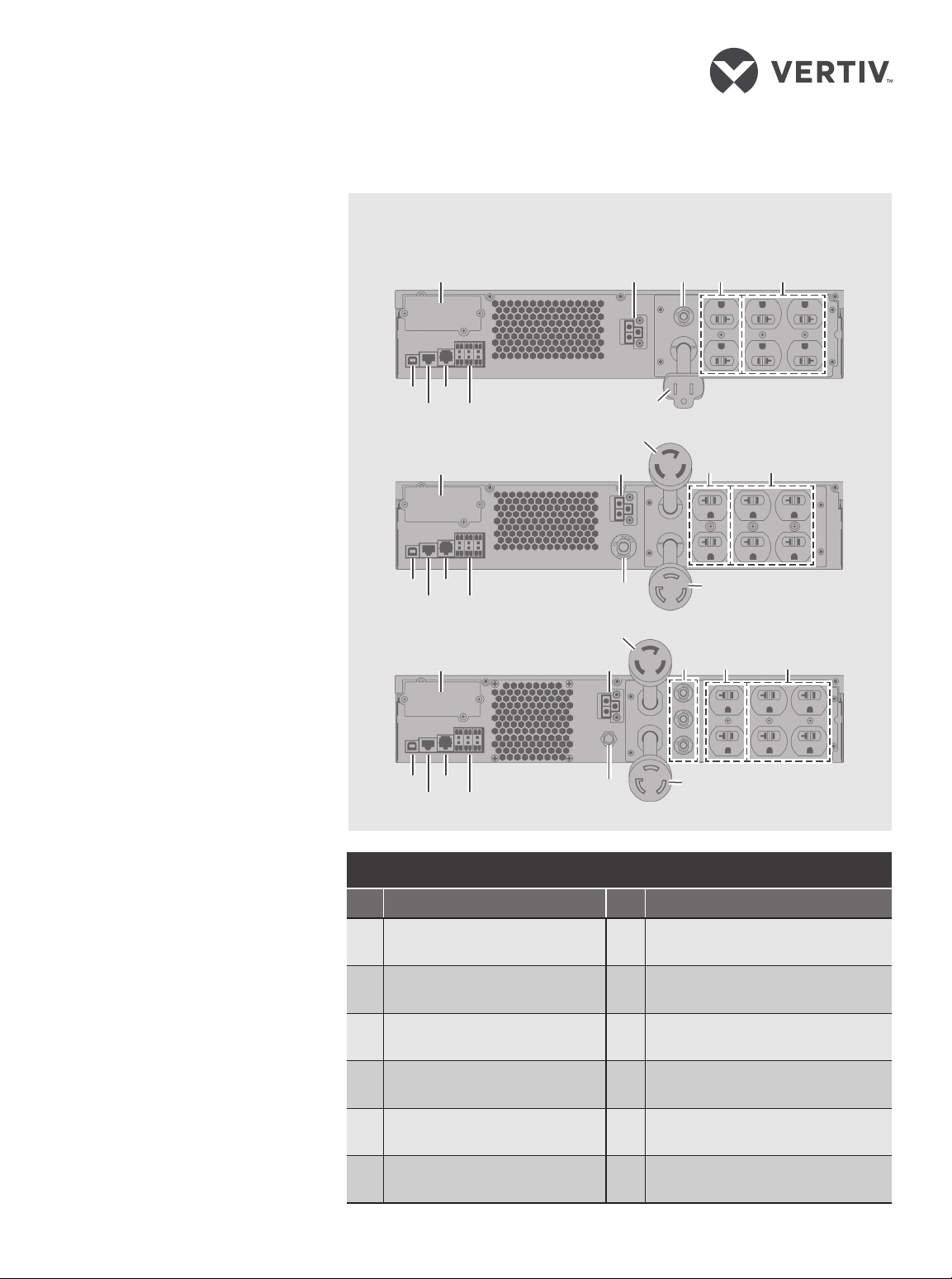
GXT5 UPS
# Description # Description
1 Liebert® IntelliSlot™ port 7 Input circuit breaker
2 USB port 8 Input-power plug and cable
3 RS-485 port 9 RS-232 port
4 External-battery connector 10
Non-programmable
5
output receptacles
Programmable
6
output receptacles
1 4 7 5 6
3 10
8
11
1 4
7
5 6
8
3 10
11
1 4
3 10
7
Terminal-block
communication connectors
11 Output-power plug and cable
12 Output circuit breaker
12
8
5 6
590-1932-501A/SL-70307_REV0 1
LIEBERT® GXT5™ UPS 120-V 500 – 3,000 VA
Quick Installation Guide
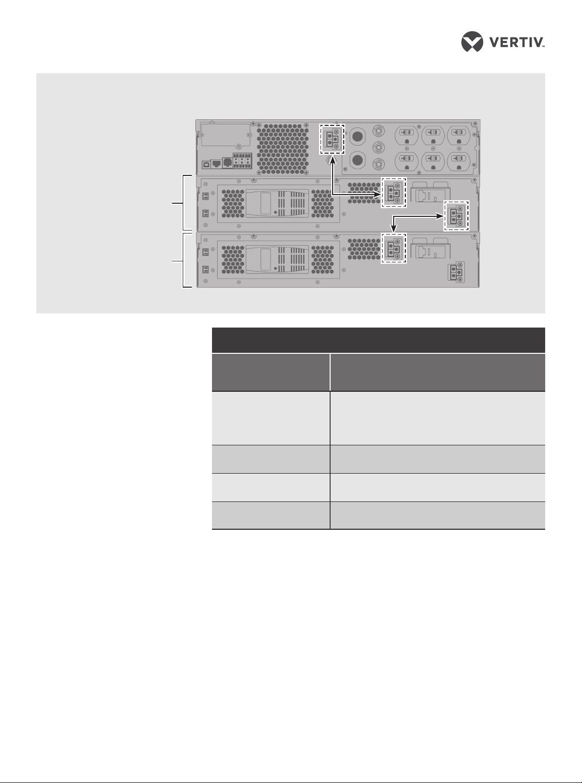
GXT5TM UPS to External Battery Cabinet Connections
GXT5‑3000LVRT2UXL
Shown
Single/First EBC
Second EBC
EBC terminal
CONNECTIONS
4. Connecting External
Battery Cabinet
(Optional)
External battery cabinets
(EBC) provide longer battery
run-time for connected
devices. Refer to GXT5 User
Guide, to select the appropriate
model and quantity for your
GXT5 model and applications.
• Verify that the EBC breaker
is in the “O” position.
• Connect one end of the
supplied EBC cable to the
UPS and one end to the
battery cabinet. If
connecting more than one
external battery, connect
one end of the external
battery cable to the second
connector on the battery
cabinet, then connect the
other end to the next
battery cabinet.
5. Connecting the UPS
to Receptacle
The UPS is cord and plug
connected using a L6-30P
input plug. Perform all wiring in
accordance to all local and
national electrical codes.
WIRING
Model
Recommended external over-current protection
GXT5-500LVRT2UXL
GXT5-750LVRT2UXL
GXT5-1000LVRT2UXL
GXT5-1500LVRT2UXL
GXT5-2000LVRT2UXL
GXT5-3000LVRT2UXL
UPS is equipped with
The
output receptacles. Connect
the equipment to be protected
to the output receptacles.
NOTE : Allow the batteries to
charge at-least 8 hours before rst
start-up to ensure adequate
back-up time. The batteries charge
when the UPS is connected to AC
input regardles of the o/on status
of the UPS.
(Maximum)
12 A
15 A
20 A
30 A
POWERING THE UPS
NOTE : Do not start the UPS until
after the installation has been
nished, the system is
commissioned by an authorized
engineer, and the external input
circuit breakers have been closed.
1. If an optional POD is installed,
make sure the bypass switch is
in “UPS” position.
2. Make sure the breaker
supplying power to the UPS is
closed, and close the input
breaker on the rear of the UPS.
2 590-1932-501A/SL-70307_REV0
 Loading...