

Vertiv LIEBERT GXT5 Series, LIEBERT GXT5-3KL620RT2UXL, LIEBERT GXT5-3KL630RT2UXL Quick Installation Manual
LIEBERT® GXT5™ UPS
208‑V3,000VA
Quick Installation Guide
I M P O RTANT: Before installing,
connecting to supply or operating
your Liebert GXT5 UPS, please
review the Safety and Regulatory
Statements sheet. For detailed
installation, operating, maintenance
and troubleshooting information
refer to the GXT5 User Guide for
your model available at
www.Vertiv.com.
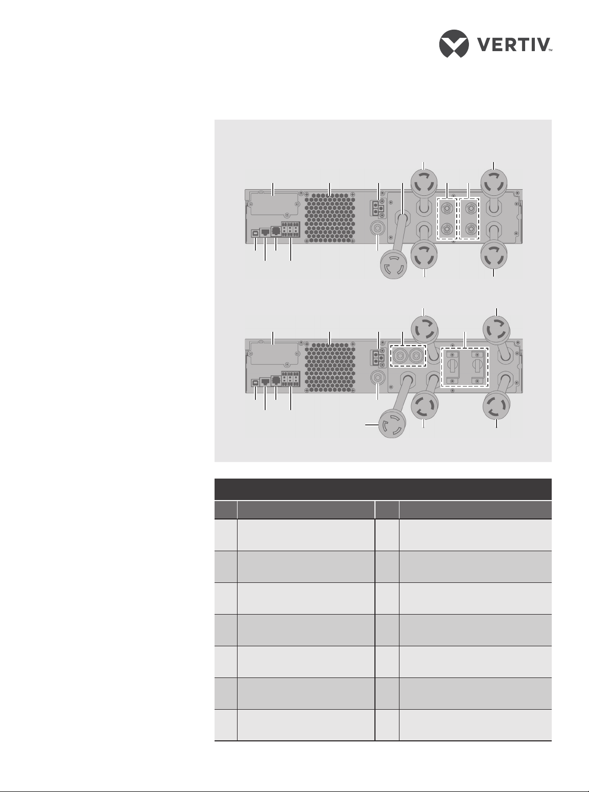
MODEL DESIGN CONFIGURATIONS
GXT5‑3KL620RT2UXL
1 4
2 3 5 7
6 8
INSTALLATION
1. Inspecting the UPS
Inspect the UPS for any signs of
obvious damage. If damage is
visible, do not proceed and call
our warranty support line for
assistance at 1-800-222-5877
menu option 3, or email at
microups.warranty@vertiv.com.
2. Choosing a location
Install the UPS in a
temperature-controlled
environment that is free of
corrosive and conductive
contaminants. Avoid locations
near heat or water sources and
exposed to direct sunlight.
For proper ventilation, leave
four inches clearance on all
sides of the UPS.
The input outlet should be
nearby and easily accessible.
GXT5 UPS
3. Installing the UPS
The UPS and optional External
Battery Cabinets may be
installed in either a tower or rack
conguration. For tower
installation, assemble and attach
the tower support stands. For
rack installation, attach the
brackets to the UPS, install the
rail kit in the rack if needed, and
install the UPS in the rack.
NOTE :
computer room as dened in the
standard for the protection of
electronic computer/data
processing equipment of ANSI/
NFPA 75.
This UPS is not for use in a
13 11
9
12 10
6 8
GXT5‑3KL630RT2UXL
1 5
13 11
12 10
2
3
9
4
6 8
7
6 8
# Description # Description
1 Liebert® IntelliSlot™ port 8 Output cable, L6-15R
2 Ventilation hole 9 Input circuit breaker
3 External-battery connector 10 Terminal-block connectors
Input-power cable: L6-20P for
4
3KL620, L6-30P for 3KL630
5 Output circuit breaker 12 RS-485 port
Output cable: L6-20R for
6
3KL620, L6-30R for 3KL630
7 Output circuit breaker
11 RS-232 port
13 USB port
SL-70377_REV1_9-19 1
LIEBERT® GXT5™ UPS 208-V 3,000 VA
Quick Installation Guide
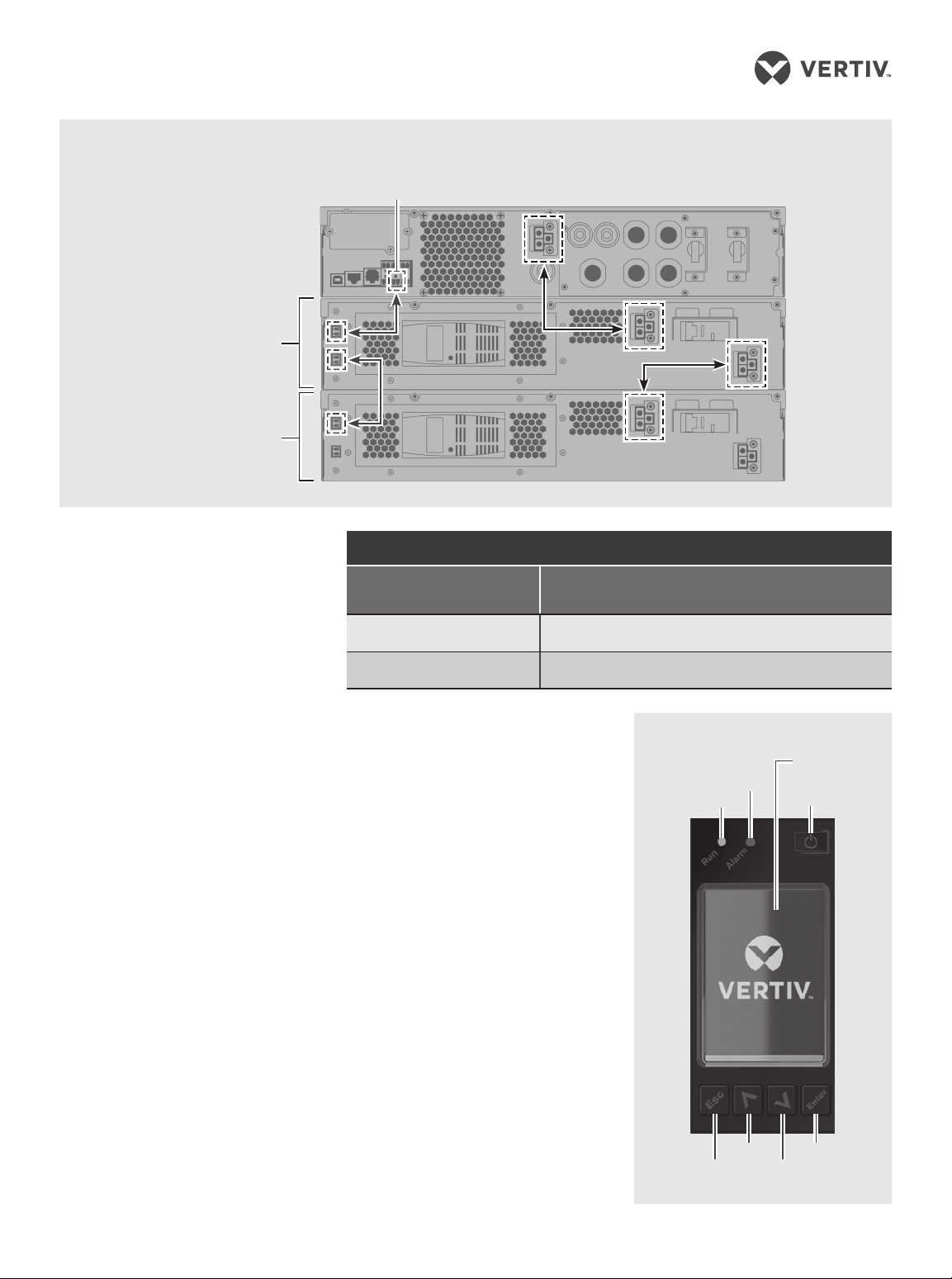
GXT5TM UPS to External Battery Cabinet Connections
EBC‑detection
dry‑contact port
GXT5‑3KL630RT2UXL
Shown
Single/First EBC
Second EBC
EBC terminal
CONNECTIONS
4. Connecting External
Battery Cabinet
(Optional)
External battery cabinets (EBC)
provide longer battery run-time
for connected devices. Refer to
GXT5 User Guide, to select the
appropriate model and quantity
for your GXT5 model and
applications.
• Verify that the EBC breaker
is in the “O” position.
• Connect one end of the
supplied EBC cable to the
UPS and one end to the
battery cabinet. If connecting
more than one external
battery, connect one end of
the external battery cable to
the second connector on the
battery cabinet, then
connect the other end to the
next battery cabinet.
5. Connecting the UPS
to Receptacle
The UPS is cord and plug
connected using an L6-20P or
L6-30P input plug depending
on your model. Perform all
wiring in accordance to all
local and national electrical
codes.
WIRING
Model
Recommended external over-current protection
(Maximum)
GX5-3KL620RT2UXL 20 A
GX5-3KL630RT2UXL 30 A
The UPS is equipped with output
receptacles. Connect the
Operation and Display Panel
equipment to be protected to the
output receptacles.
NOTE : Allow the batteries to
charge at-least 8 hours before rst
start-up to ensure adequate
back-up time. The batteries charge
when the UPS is connected to AC
input regardles of the o/on status
of the UPS.
POWERING THE UPS
NOTE : Do not start the UPS until
after the installation has been
nished, the system is
commissioned by an authorized
engineer, and the external input
circuit breakers have been closed.
1. Make sure the breaker
supplying power to the UPS is
closed, and close the input
breaker on the rear of the UPS.
Escape
Alarm
Run
Up
Display
screen
Power
Enter
Down
2 SL-70377_REV1_9-19

LIEBERT® GXT5™ UPS 208-V 3,000 VA
Quick Installation Guide
2. If necessary, use the LCD
display or a connected
computer to make any required
settings. (Refer to the User
Guide for conguration set up.)
3. Close all output breakers on
the rear of the UPS (or in an
external panel board, if used).
4. If external battery cabinets are
included, close the breakers on
the rear of each cabinet.
5. Power-on the UPS using the
Operation and Display Panel
(see the illustration on the
previous page) by pressing and
holding the power button until
the conrmation dialog
appears. Use the Up/Down
arrows to select “YES”, then
press Enter.
NOTE : During operation, the UPS
may sound an alarm as the output
receptacles are powered. You may
press the Esc button for 2 seconds
to silence the audible alarm.
SL-70377_REV1_9-19 3

To contact Vertiv Technical Support: visit www.Vertiv.com
© 2019 Vertiv Group Corp. All rights res erved. Vertiv and the Vertiv logo are trade marks or registered trademarks of Vertiv G roup Corp. Al l other names and logos referred to are
trade nam es, trademarks or regis tered trademarks of their re spective owners. While every prec aution has been taken to ens ure accuracy and completeness herein, Vertiv Gro up
Corp. as sumes no responsibility, and discla ims all liabil ity, for damages resulting from use of this information or for any errors or omissions. Specications are su bject to change
without notice.
4 SL-70377_REV1_9-19
 Loading...