

Vertiv Liebert GXT5-3000LVRT2UXL, Liebert GXT5-500LVRT2UXL, Liebert GXT5-750LVRT2UXL, Liebert GXT5-1000LVRT2UXL, Liebert GXT5-1500LVRT2UXL Installer And User Manual
...
Liebert®
GXT5™ UPS
Installer/User Guide
120V, 500 VA to 3,000 VA

The information contained in this document is subject to change
without notice and may not be suitable for all applications. While
every precaution has been taken to ensure the accuracy and
completeness of this document, Vertiv assumes no responsibility
and disclaims all liability for damages resulting from use of this
information or for any errors or omissions. Refer to other local
practices or building codes as applicable for the correct methods,
tools, and materials to be used in performing procedures not
specifically described in this document.
The products covered by this instruction manual are manufactured
and/or sold by Vertiv. This document is the property of Vertiv and
contains confidential and proprietary information owned by Vertiv.
Any copying, use or disclosure of it without the written permission
of Vertiv is strictly prohibited.
Names of companies and products are trademarks or registered
trademarks of the respective companies. Any questions regarding
usage of trademark names should be directed to the original
manufacturer.
Technical Support Site
If you encounter any installation or operational issues with your product, check the pertinent
section of this manual to see if the issue can be resolved by following outlined procedures.
Visit https://www.Vertiv.com/en-us/support/ for additional assistance.
Vertiv | Liebert® GXT5™ Installer/User G uide

TABLE OF CONTENTS
Important Safety Information 1
1 GXT5 Description 3
1.1 UPS Features and Available Models 3
1.2 Front Panels 4
1.3 Rear Panels 4
1.4 Battery Cabinet 7
1.5 Major Internal Components and Operating Principle 7
1.6 UPS States and Operating Modes 9
1.6.1 Normal Mode 9
1.6.2 Bypass Mode 10
1.6.3 Battery Mode 10
1.6.4 Frequency Converter Mode 10
1.6.5 ECO Mode 10
2 Installation 11
2.1 Unpacking and Inspection 11
2.2 Pre-installation Preparation 11
2.2.1 Installation Clearances 11
2.3 Installing the UPS 11
2.3.1 Tower Installation 12
2.3.2 Rack Installation 12
2.4 Installing External Battery Cabinets 12
2.5 Connecting AC Input Power 15
2.6 Connecting Loads 15
2.7 Communication Connections 15
2.7.1 Connecting IntelliSlot Communication 16
2.7.2 Connecting to the Dry-contact Port 16
2.7.3 Connecting a Remote Emergency Power-off (REPO) Switch 17
2.7.4 Connecting a USB Cable 18
2.7.5 Connecting CLI Communication Cables 18
2.7.6 Connecting Sensors to the Control Port 19
3 Operating the UPS 21
3.1 Silencingthe Audible Alarm 21
3.2 Starting-up the UPS 21
3.3 Transferring to Battery Mode 22
3.4 Transferring from Normal to Bypass Mode 22
3.5 Transferring from Bypass to Normal Mode 22
3.6 Shutting-down the UPS Completely 22
3.7 Remote Emergency Power-off (REPO) 22
4 Operation and Display Panel 23
4.1 LED Indicators 25
Vertiv | Liebert® GXT5™ Installer/User Guide | iii

4.2 LCD Menu and Screens 25
4.2.1 Start-up and Flow Screens 25
4.2.2 Main Menu 26
4.3 Editing Display and Operation Settings 41
4.3.1 Changing the Password 41
4.3.2 Selecting the Display Language 42
4.3.3 Setting the Date and Time 42
5 Maintenance 43
5.1 Replacing Batteries 43
5.2 Charging Batteries 45
5.3 Checking UPS Operation 46
5.4 Cleaning the UPS 46
6 Troubleshooting 47
6.1 Symptoms that Require Troubleshooting 47
6.2 Audible Alarm (Buzzer) 47
6.2.1 Faults 47
6.3 Troubleshooting UPS Issues 48
7 Specifications 49
7.1 Battery Run Times 54
Appendices 57
Appendix A: Technical Support 57
Vertiv | Liebert® GXT5™ Installer/User Guide | iv

IMPORTANT SAFETY INFORMATION
IMPORTANT! This manual contains important safety instructions that must be followed during the
installation and maintenance of the UPS and batteries. Read this manual thoroughly and the safety and
regulatory information, available at https://www.vertivco.com/ComplianceRegulatoryInfo, before
attempting to install, connect to supply, or operate this UPS.
1

This page intentionally left blank
2
Vertiv | Liebert® GXT5™ Installer/User G uide
1 GXT5 DESCRIPTION
The Liebert® GXT5 is a compact, online uninterruptible power system (UPS) that continuously conditions
and regulates its output voltage. The Liebert® GXT5 supplies microcomputers and other sensitive
equipment with clean sine-wave input power.
Upon generation, AC power is clean and stable. However, during transmission and distribution it is subject
to voltage sags, spikes, and complete failure that may interrupt computer operations, cause data loss, and
damage equipment.
The Liebert® GXT5 protects equipment from these disturbances. The Liebert® GXT5 continuously
charges its batteries from the utility power, enabling it to supply power to connected loads, even when the
mains fail.
1.1 UPS Features and Available Models
The GXT5 includes the following features. Table 1.1 below, lists the available models and power ratings.
• Enhanced load capacity with an output power factor of 1.
• Input power factor greater than 0.99
• Optional tower or rack installation to meet varying installation requirements.
• Adapts to areas with unstable power-mains supply via high-frequency double-conversion
topology structure, with high input-power factor, wide input-voltage range, and output
immune to grid interference.
• Full digital-control platform and hardware-design platform adapts to unstable mains supply
and load impact
• Programmable terminals with cascade protection protect key devices when load is heavy.
• Operation and display panel with model-specific color LCD offers simple configuration and
control of the UPS.
• ECO power-supply mode and smart-sleep mode help you save the maximum amount of energy.
1 GXT5 Description
Table 1.1 UPS Models and Power Ratings
MODEL NU MBER NOMINAL POWER RATING
GXT5-500LVRT2UXL 500VA/500W
GXT5-750LVRT2UXL 750VA/750W
GXT5-1000LVRT2UXL 1000VA/1000W
GXT5-1500LVRT2U XL 1500VA/1350W
GXT5-2000LVRT2UXL 2000VA/1800W
GXT5-3000LVRT2UXL 3000VA/2700W
3
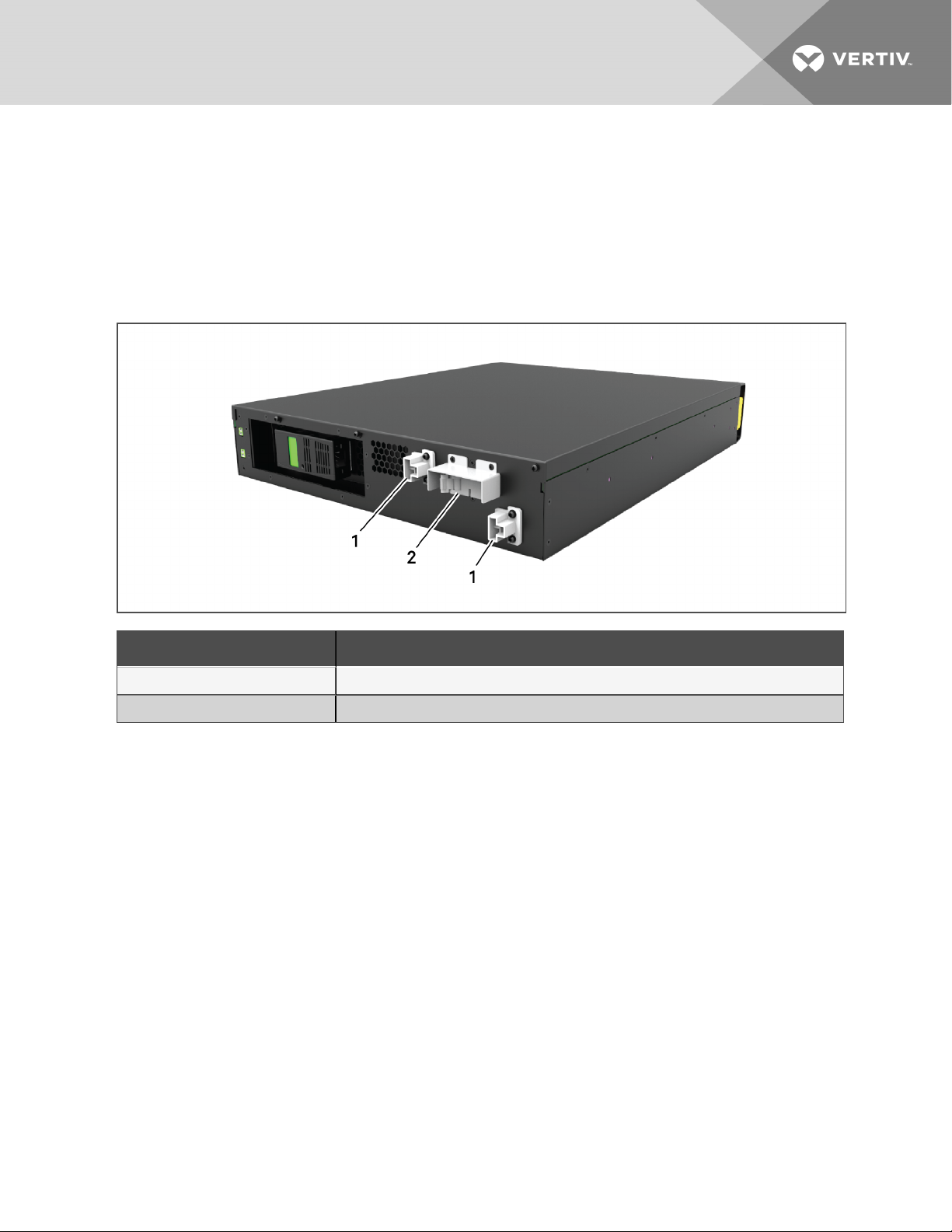
1.2 Front Panels
The various GXT5 models have the same general appearance, with the main difference being the
receptacle types on the rear panel.
Figure 1.1 Front View
1.3 Rear Panels
The following figures detail the rear-panel features for each GXT5 model.
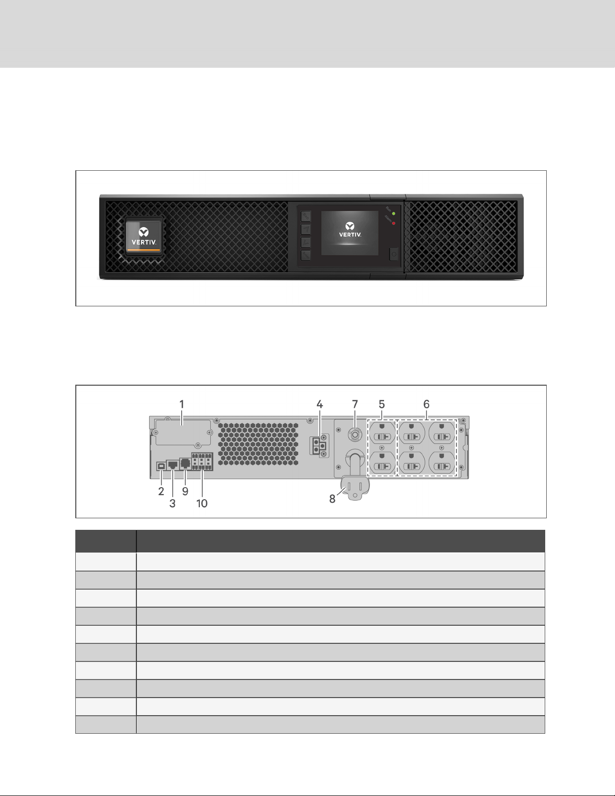
Figure 1.2 GXT5-500/750/1000/1500LVRT2UXL Rear Panel
ITEM DESCRIPTION
1 Liebert® IntelliSlot™ port
2 USB port
3 RS-485 port
4 External-battery connector
5 Non-programmable output receptacles, IEC-60906-1 15-A
6 Programmable output receptacles, IEC-60906-1 15-A
7 Input circuit breaker
8 Input-power plug and cable, IEC-60906-1 15-A
9 RS-232 port
10 Terminal-block communication connectors
4
Vertiv | Liebert® GXT5™ Installer/User G uide
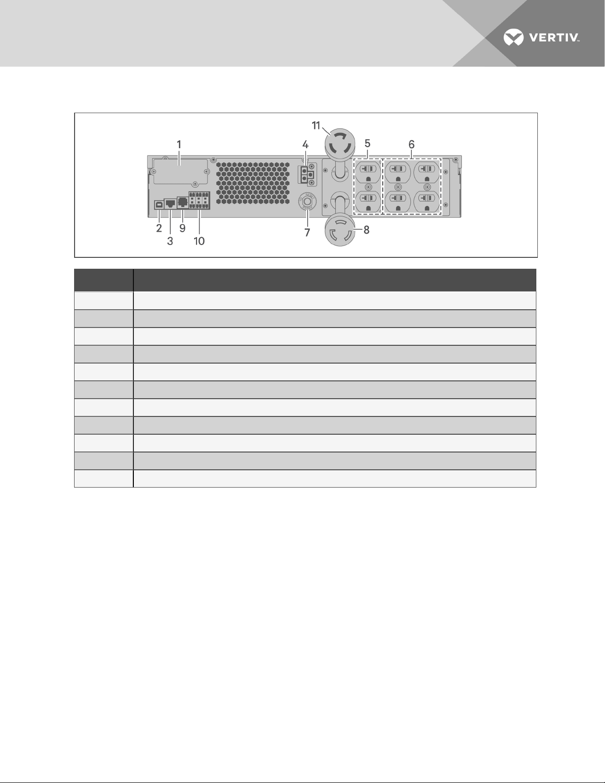
Figure 1.3 GXT5-2000LVRT2UXL Rear Panel
ITEM DESCRIPTION
1 Liebert® IntelliSlot™ port
2 USB port
3 RS-485 port
4 External-battery connector
5 Non-programmable output receptacles, IEC-60906-1 20-A
6 Programmable output receptacles
7 Input circuit breaker
8 Input-power plug and cable, L5-20P
9 RS-232 port
10 Terminal-block communication connectors
11 Output-power plug and cable, L5-20R
1 GXT5 Description
5
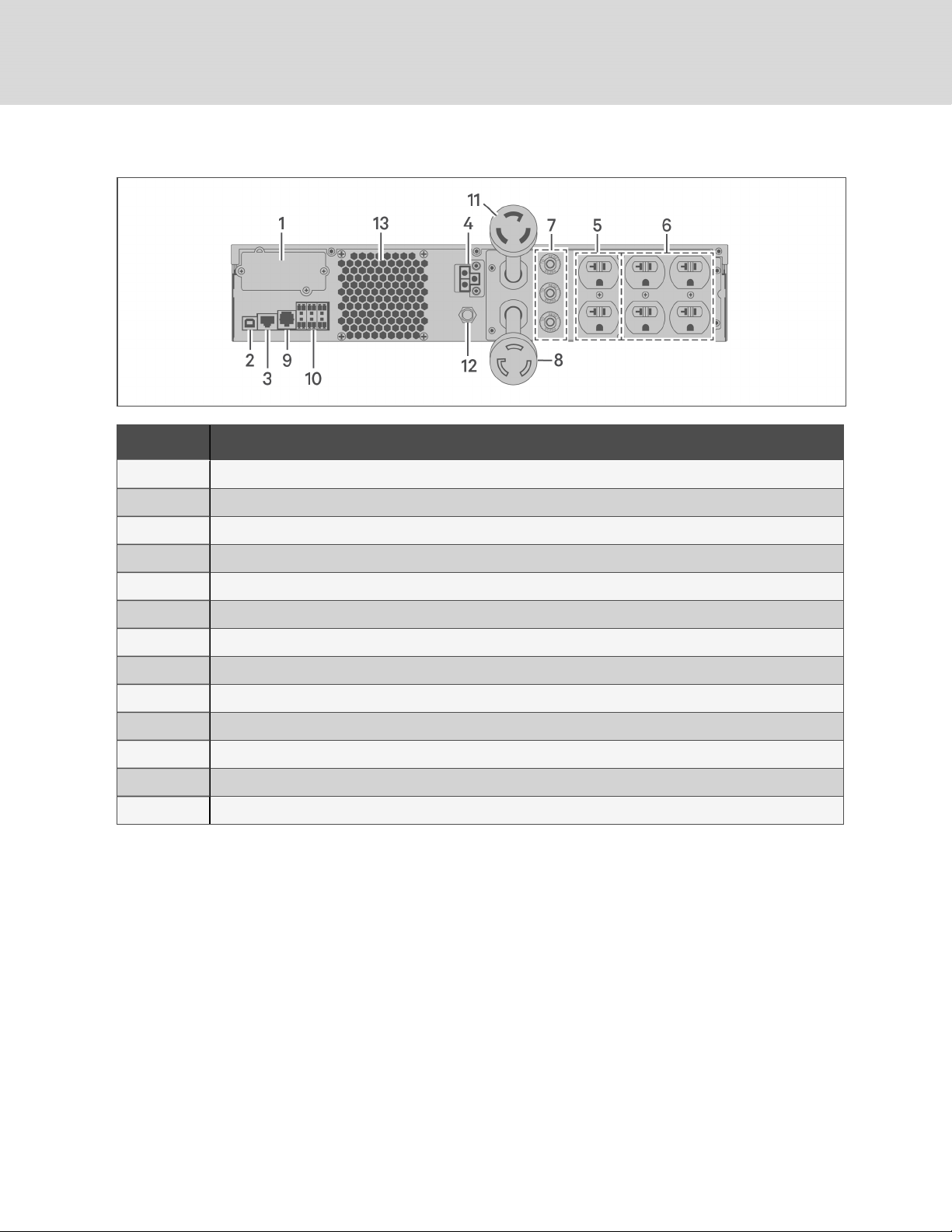
Figure 1.4 GXT5-3000LVRT2UXL Rear Panel
ITEM DESCRIPTION
1 Liebert® IntelliSlot™ port
2 USB port
3 RS-485 port
4 External-battery connector
5 Non-programmable output receptacles, IEC-60906-1 20-A
6 Programmable output receptacles
7 Output circuit breakers
8 Input-power plug and cable, L5-30P
9 RS-232 port
10 Terminal-block communication connectors
11 Output-power plug and cable, L5-30R
12 Input circuit breaker
13 Coolingfan
6
Vertiv | Liebert® GXT5™ Installer/User G uide
1.4 Battery Cabinet
Optional battery cabinets are available for the UPS, and include a single battery-connector cable. Up to 10
battery cabinets may be connected in parallel to the UPS, and up to 6 can be detected using EBCdetection. See External Battery Cabinet Specifications on page53, for the cabinet specifications. For
approximate battery run times with additional EBCs, see Battery Run Times on page54. See Installing
External Battery Cabinets on page12, to connect the cabinets.
Figure 1.5 Battery Cabinet
ITEM. DESCRIPTION
1 Battery connectors
2 Isolation breaker
1.5 Major Internal Components and Operating Principle
Figure 1.6 on the next page, shows the UPSoperating principle. Table 1.2 on page9, describes the
function of the major components in the UPS.
NOTE: Figure 1.6 on the next page, is one example of basic operation.
1 GXT5 Description
7
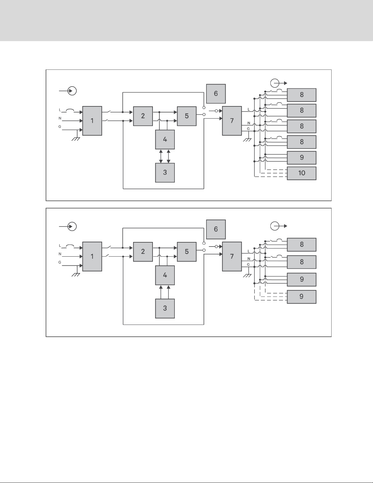
Figure 1.6 Basic Operating Principle Diagram
8
Vertiv | Liebert® GXT5™ Installer/User G uide

Table 1.2 Major Components
ITEM COMPONENT OPERATION/FUNCTION
Transient
Voltage Surge
1
Suppression
(TVSS)and
EMI/RFI Filters
Provide surge protection. Filter electromagnetic interference (EMI) andradio frequency interference
(RFI). Minimize surges or interference present in the utility power and protect devices connected on the
same branch as the UPS.
Rectifier/Power
2
3 Batteries
4
5 Inverter
6
7 EMI/RFI Filters
8 Outlet group Programmable output receptacles.
9 Outlet group General output receptacles.
Factor
Correction
(PFC) Circuit
DC-to-DC
Converter
Dynamic
Internal Bypass
In normal operation, converts utility ACpower to regulated DC power for use bythe inverter while
ensuring that the wave shape of the input current used bythe UPS isnear ideal. Extracting this sine-wave
input current ensures efficient use of utility power and reduces reflected harmonic distortion making
cleaner power available to devices that are not protected bythe UPS.
Valve-regulated, non-spillable, lead-acid batteries.
NOTE: To maintain battery design life, operate the UPS in an ambient temperature of 59°F to 77°F
(15°C to 25°C).
Raises the DC voltage from the battery to the optimum operating voltage for the inverter. This allows the
inverter to operate continuouslyat its optimum efficiency and voltage, thus increasingreliability.
In normal operation, inverts the DC output of the PFC c ircuit into precise, regulated sine-wave AC power.
When utility power fails, the inverter receives DC power from the DC-to-DC converter. In either
operating mode, the UPS inverter remains on-line, generating clean, precise, regulated AC-output
power.
In the unlikelyevent of UPS failure such as overload or over-temperature, automatically transfers the
connected load to bypass.
To manually transfer the connected load from inverter to bypass, see Transferring from Normal to
Bypass Mode on page22.
Filter electromagnetic interference (EMI) andradio frequency interference (RFI). Minimize interference
present in the utility power and protect devices connected on the same branch as the UPS.
10 Outlet group General output receptacles on 2,000- and 3,000-VA models only.
1.6 UPS States and Operating Modes
NOTE: See LED Indicators on page25, for description of the run-indicator and alarm-indicator LEDs
mentioned in this section.
1.6.1 Normal Mode
When utility power is normal, Normal mode employs the rectifier and inverter to provide voltage- and
frequency-stabilized power to the load. The charger charges the battery in normal mode. On the frontpanel display, the run-indicator (green)is On, the alarm indicator is OFF, and the buzzer is silent.
1 GXT5 Description
9

1.6.2 Bypass Mode
Bypass mode supplies power to the load from the bypass source (utility power) if an overload or fault
occurs during normal operation. On the front-panel display, the run indicator (green) is On, the alarm
indicator (yellow)is On, and the buzzer beeps once each seconds. The LCD "Current" screen displays "On
Bypass."
NOTE: If utility power fails or if the utility voltage goes outside of the permissible range during bypassmode operation, the UPS shuts down and no output is supplied to the load.
1.6.3 Battery Mode
Battery mode supplies battery power to the load if utility power fails or if the utility voltage goes outside of
the permissible range. On the front-panel display, the run indicator (green) is On, the alarm indicator
(yellow)is On, and the buzzer beeps once each second. The LCD "Current" screen displays "On Battery."
NOTE: The batteries are fully-charged before shipment. However, transportation and storage
inevitably cause some loss of capacity. To ensure adequate back-up time, charge the batteries for atleast 8 hours before first start-up.
NOTE: If utility power fails and the batteries are charged, you may cold-start the UPS in battery mode
and use battery power to extend system availability for a time.
NOTE: Powering-off the UPS when it is in battery mode results in loss of output power to the
connected load.
1.6.4 Frequency Converter Mode
All models of the GXT5 are capable of frequency conversion. Frequency Conversion Mode can be selected
using the configuration program. Allowable frequency operating modes include:
• Auto Sensing - 50 Hz or 60Hz – Bypass Enabled
• Auto Sensing - 50 Hz or 60Hz – Bypass Disabled
• Frequency Converter - 50 Hz – Bypass Disabled
• Frequency Converter - 60Hz – Bypass Disabled
NOTE: The default for all models of the Liebert® GXT5 is “Auto Sensing - 50 Hz or 60Hz – Bypass
Enabled.”
1.6.5 ECO Mode
The energy-saving ECO mode reduces power consumption by powering the load via bypass if the bypass
voltage is normal or by powering the load via the inverter when the bypass voltage is abnormal. You can
use ECOmode to power equipment that is not sensitive to power-grid quality to via bypass and reduce
power consumption.
NOTE: During Eco mode, if a bypass-failure or abnormal-bypass-voltage notification appears when the
output is not overloaded, the UPS will transfer to Normal Mode. However, if a notification showing
bypass failure or abnormal bypass voltage appears when the output is overloaded, the UPS will shut
down the bypass.
10
Vertiv | Liebert® GXT5™ Installer/User G uide

2 INSTALLATION
Do not start the UPS until after the installation is finished.
WARNING! Risk of electrical shock. Can cause equipment damage, injury and death. Before
beginning installation, verify that all external overcurrent protection devices are open (Off), and
that they are locked-out and tagged appropriately to prevent activation during the installation,
verify with a voltmeter that power is Off and wear appropriate, OSHA-approved personal
protective equipment (PPE) per NFPA 70E. Failure to comply can cause serious injury or death.
Before proceeding with installation, read all instructions. Follow all local codes.
2.1 Unpacking and Inspection
Unpack the UPS and conduct the following checks:
• Inspect the UPS for shipping damage. If any shipping damage is found, report it to the carrier
and your local Vertiv representative immediately.
• Check the accessories included against the packing list. If there is any discrepancy, contact
your local Vertiv representative immediately.
CAUTION: The UPS is heavy (see Specifications on page49, for the weight). Take proper
precautions when lifting or moving the unit.
2.2 Pre-installation Preparation
• Install the UPS indoors in a controlled environment, where it cannot be accidentally turned Off.
The installation environment should meet the specifications listed in Specifications on
page49.
• Place the UPS in an area of unrestricted air-flow around the unit, away from water, flammable
liquids, gases, corrosives, and conductive contaminants. Avoid direct sunlight
NOTE: Operating the UPS in temperatures above 77°F (25°C) reduces battery life.
2.2.1 Installation Clearances
Maintain at least 4in.(100mm) clearance in the front and rear of the UPS. Do not obstruct the air inlets on
the front panel and rear panel of the UPS. Blocking the air inlets reduces ventilation and heat dissipation,
shortening the service life of the unit.
2.3 Installing the UPS
The UPS may be installed as a tower or in a rack, depending on available space and use considerations.
Determine the type of installation and follow the appropriate instructions. See Tower Installation on the
next page or Rack Installation on the next page.
NOTE: When installing the UPS or making input and output connections, comply with all relevant
safety codes and standards
2 Installation
11
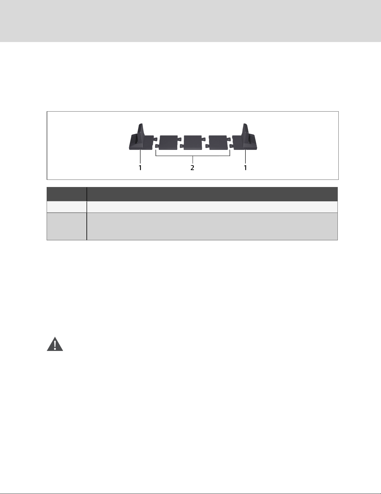
2.3.1 Tower Installation
To install the UPS as a tower:
1. Take the support bases out of the accessories box.
Figure 2.1 Support bases
NO. D ESCRIPTION
1 Support bases
Spacers with connectors
2
NOTE: Three spacers are shown here. However, the number of spacers varies depending on your UPS
model and the number of battery cabinets in your system.
2. If optional, Liebert® external battery cabinets will be connected, take out the spacers shipped
with the battery cabinet.
3. Connect the spacers and the support bases as shown in Figure 2.1 above. Each GXT5 requires
2support bases, one in the front and one in the rear.
4. Place the GXT5 and any battery cabinets on the 2support bases.
2.3.2 Rack Installation
When installed in a rack enclosure, the GXT5 UPS and external battery cabinets (EBC) must be supported
by a shelf or rack-mount rails. Because different rack-mount options install differently, refer to the
installation instructions provided with the rack-mount kit.
CAUTION: The GXT5 is heavy. The UPS must be installed as near the bottom of a rack as
possible. If placed too high, it can make the rack top-heavy and prone to tipping over. For unit
weights, see Specifications on page49.
2.4 Installing External Battery Cabinets
Optional, external battery cabinets (EBC) may be connected in parallel to the UPS to provide additional
battery run time. For approximate battery run times with additional EBCs, see Battery Run Times on
page54.
External battery cabinets are placed on one side of the UPS in a tower configuration or stacked beneath
the UPS in a rack configuration. Up to 10 EBCs may be connected to the UPS, and up to 6 may be
detected using EBC-detection.
12
Vertiv | Liebert® GXT5™ Installer/User G uide

WARNING! Risk of electric shock. Can cause injury or death. Disconnect all local and remote
electric power supplies before working with the UPS. Ensure that the unit is shut down and
power has been disconnected before beginning any maintenance.
CAUTION: The external battery cabinet(s) are heavy, see Table 7.3 on page53. Take proper
precautions when lifting them.
To install the EBC(s):
1. Inspect the EBC for freight damage. Report damage to the carrier and your local dealer or
Vertiv representative.
2. For tower installation:
• An additional set of support-base extensions ships with each EBC.
• See the steps in Tower Installation on the previous page, to connect the support
extenders and install the bases.
– or –
For rack installation:
• Rack-mount hardware ships with the EBC.
• Refer to the instructions included with the rack-mount kit to install.
NOTE: Optional slide rails and securing hardware are sold separately. Please contact your Vertiv
representative for options and Vertiv Technical Support for assistance.
3. Verify that the EBC breaker is in the "Off" position.
4. Connect the supplied EBC cable(s) to the rear of the cabinet, then to the rear of the UPS, see
Figure 2.2 on the next page.
5. Turn the EBC breaker to the "On" position.
6. Verify the circuit breaker on the EBC is in the "On" position.
The additional back-up run time is enabled.
NOTE: When removing an EBC, turn off the circuit breaker on the rear of the cabinet before
disconnecting the cable.
NOTE: If shipping or storing the UPS for an extended time, disconnect the EBC(s) minimize stand-by
current drain on the batteries and help maintain design life.
2 Installation
13
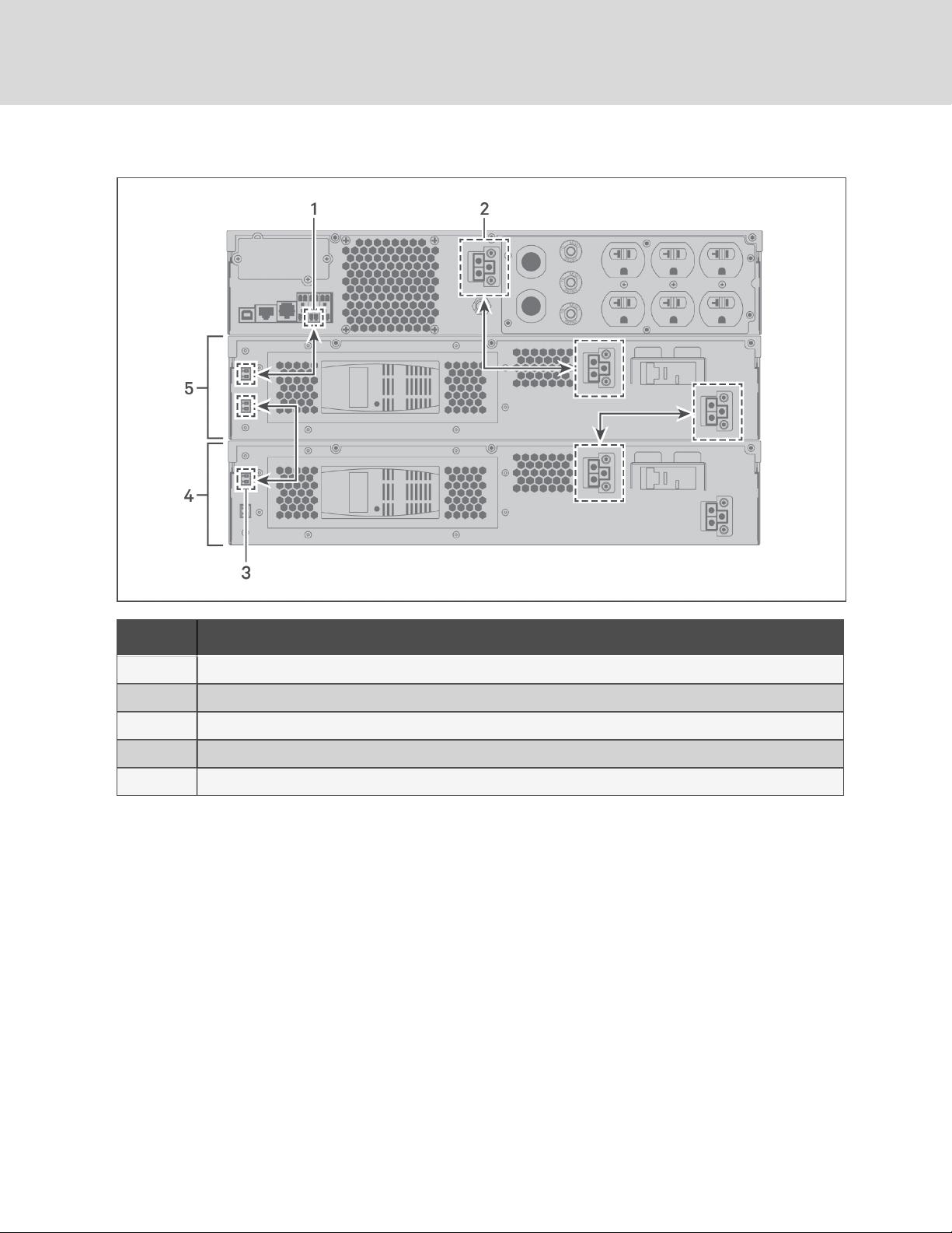
Figure 2.2 EBCs connected to the UPS
ITEM DE SCRIPTION
1 EBC-detection dry-contact port (See Table 2.2 on page17, for details.)
2 EBC connector
3 EBC-detection port
4 External battery cabinet
5 Externalbattery cabinet
14
Vertiv | Liebert® GXT5™ Installer/User G uide
2.5 Connecting AC Input Power
Ensure that all the loads are turned Off. Prepare an input power supply that is properly protected by a
circuit breaker in accordance with national and local electrical codes. The wall receptacle must be
grounded. We recommend installing an upstream circuit breaker of the same series as the input circuit
breaker of the GXT5.
Table 2.1 below, lists the specifications of the input circuit breaker on the rear panel by UPS model
Table 2.1 Input circuit breaker
specifications
MODEL RATED CI RCUIT BREAKER
GXT5-500LVRT2UXL 12A
GXT5-750LVRT2UXL 12A
GXT5-1000LVRT2UXL 12A
GXT5-1500LVRT2U XL 15A
GXT5-2000LVRT2UXL 20A
GXT5-3000LVRT2UXL 30A
To connect AC-input power, plug the input plug of the UPS into the input-power connection.
NOTE: If the input plug will serve as the disconnecting device, the wall socket/outlet must be near the
UPS and must be easily accessible, per the National Electric Code/NFPA 70 requirements.
2.6 Connecting Loads
500-VA to 1500-VA models have five groups of outlets:
• One group is not programmable (always On).
• Four groups are controlled with programmed responses or an SNMP network.
2000-VA and 3000-VA models have six groups of outlets:
• Two groups are not programmable (always On).
• Four groups are controlled with programmed responses or an SNMP network.
NOTE: When connecting load, verify that the equipment is plugged into the appropriate outlets if any
of the outlets will be controlled.
NOTE: Do not overload any output receptacle. Output cable length should not exceed 10m (32.8ft).
To connect equipment, plug equipment into the appropriate output receptacles on the rear of the UPS,
see the appropriate figure for your model in Rear Panels on page4.
2.7 Communication Connections
The UPS offers several communication interfaces and ports.
NOTE: We recommend that signal-cable lengths be less than 10ft(3m), and are kept away from power
cabling.
2 Installation
15
2.7.1 Connecting IntelliSlot Communication
The IntelliSlot ports accepts two optional cards:
The Liebert® IntelliSlot™ Relay card (IS-RELAY) card provides dry-contact relay output for custom-wired
applications.
The Liebert® IntelliSlot™ Unity card (RDU101) provides SNMP monitoring of the UPS across the network
and/or building management system and lets you monitor external temperature, humidity and contactclosure inputs using external sensors.
See the appropriate figure for your model in Rear Panels on page4, for the location of the card port.
To install an IntelliSlot Card:
1. Remove the screws from the slot cover plate and remove the plate.
2. Insert the card into the slot, and secure with the screws that held the cover plate.
To make connections to the card, refer to the Installer/User Guide for the appropriate IntelliSlot card
available at www.Vertiv.com.
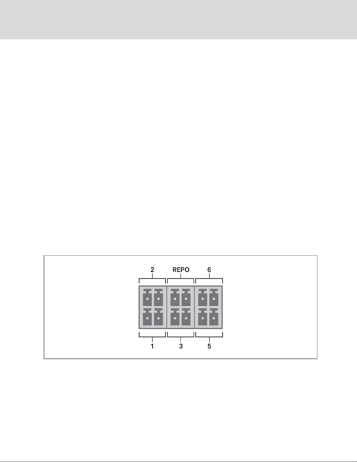
2.7.2 Connecting to the Dry-contact Port
The UPS includes a dry-contact port. See the appropriate figure for your model in Rear Panels on page4,
for the location of the port. Figure 2.3 below, shows the ports and Table 2.2 on the facing page,
describes each port.
The I/O dry contact port capacity is 125Vdc, 0.5A; 30Vdc, 1A
Figure 2.3 Dry-contact Port and Pin Layout
NOTE: Pins 7 and 8 are shorted before delivery.
NOTE: The emergency power-off (EPO) action of the UPS closes the rectifier, inverter and static
bypass, but it cannot disconnect the UPS mains input inside. To completely disconnect the UPS,
disconnect the upstream input circuit breaker when generating the EPO. For details on
REPOconnection and operation, see Connecting a Remote Emergency Power-off (REPO) Switch on
the facing page.
16
Vertiv | Liebert® GXT5™ Installer/User G uide
 Loading...