

Vertiv Liebert GXT4-3000RT208, Liebert GXT4-500RT120, Liebert GXT4-700RT120, Liebert GXT4-1000RT120, Liebert GXT4-1500RT120 Installer/user Manual
...
Liebert®
GXT4™ UPS
Installer/User Guide
120V/208V, 500VA – 3000VA

The information contained in this document is subject to change
without notice and may not be suitable for all applications. While
every precaution has been taken to ensure the accuracy and
completeness of this document, Vertiv assumes no responsibility
and disclaims all liability for damages resulting from use of this
information or for any errors or omissions. Refer to other local
practices or building codes as applicable for the correct methods,
tools, and materials to be used in performing procedures not
specifically described in this document.
The products covered by this instruction manual are manufactured
and/or sold by Vertiv. This document is the property of Vertiv and
contains confidential and proprietary information owned by Vertiv.
Any copying, use or disclosure of it without the written permission
of Vertiv is strictly prohibited.
Names of companies and products are trademarks or registered
trademarks of the respective companies. Any questions regarding
usage of trademark names should be directed to the original
manufacturer.
Technical Support Site
If you encounter any installation or operational issues with your product, check the pertinent
section of this manual to see if the issue can be resolved by following outlined procedures.
Visit https://www.VertivCo.com/en-us/support/ for additional assistance.
Vertiv | Liebert® GXT4™Installer/User Guide

TABLE OF CONTENTS
1 Important Safety Precautions 5
2 GXT4 Description 9
2.1 Features 9
2.2 Available Models 9
2.3 Front Panel and Controls 10
2.4 Rear Panel Features 10
2.5 Major Components 15
2.5.1 Transient Voltage Surge Suppression (TVSS) andEMI/RFIFilters 16
2.5.2 Rectifier/Power Factor Correction (PFC) Circuit 16
2.5.3 Inverter 16
2.5.4 Battery Charger 16
2.5.5 DC-to-DC Converter 17
2.5.6 Battery 17
2.5.7 Dynamic Bypass 17
2.5.8 Battery Cabinet 17
2.6 Operating Modes 18
2.6.1 Mains Mode 18
2.6.2 Manual Bypass Mode 18
2.6.3 Battery Mode 19
2.6.4 Battery Recharge Mode 19
2.6.5 Frequency Converter Mode 19
2.6.6 Active ECO Mode 19
3 Installation 21
3.1 What’s Included 21
3.2 Unpacking and Inspection 21
3.3 Preparation for Installation 21
3.3.1 Installation Environment 21
3.3.2 Installation Clearances 22
3.4 Installing the UPS 22
3.4.1 Tower Installation 22
3.4.2 Rack Installation 23
3.4.3 Connecting Cables 24
3.4.4 Connecting to AC Mains and Loads 24
3.4.5 Connecting Battery Cables 25
3.4.6 Connecting USB Communication Cables 25
3.4.7 Installing the Optional Liebert® IntelliSlot™ Card andCommunication Cables 25
4 Operation and Display Panel 27
4.1 LED Indicators 28
4.2 Control Buttons 28
4.3 LCD 28
Vertiv | Liebert® GXT4™ Installer/User Guide | 3

4.4 Menu Structure 29
4.4.1 Startup Screen 30
4.4.2 Default Screen 30
4.4.3 Main Menu Screen 30
4.5 Prompt List 33
4.6 Warning List 34
4.7 Fault List 34
5 Operation 37
5.1 Startup Checklist for the GXT4 37
5.2 Starting the UPS 37
5.3 Performing a Manual Battery Test 37
5.4 Performing Manual Bypass 38
5.5 Shutting Down the GXT4 38
5.6 Disconnecting Input Power from the GXT4 38
6 Communication 39
6.1 Liebert® IntelliSlot Communication Cards 39
6.2 USB Port Communication 39
6.2.1 Configuration Program 39
6.3 Terminal Block Communication 41
6.3.1 Any Mode Shutdown 41
6.3.2 Battery Mode Shutdown 42
6.3.3 On Battery 42
6.3.4 Low Battery 42
7 Maintenance 43
7.1 Replacing the Internal Battery Pack 43
7.1.1 Battery Replacement Procedures 44
7.2 Charging Batteries 46
7.3 Precautions 46
7.4 Checking UPS Status 46
7.5 Checking UPS Functions 47
8 Troubleshooting 49
8.1 Symptoms that Require Troubleshooting 49
8.1.1 Faults 49
8.1.2 Audible Alarm 50
8.2 Troubleshooting UPS Issues 50
9 Specifications 53
9.1 Auto-Learning Battery Run Times 60
Appendices 63
Appendix A: Technical Support 63
Vertiv | Liebert® GXT4™ Installer/User Guide | 4

1 IMPORTANT SAFETY PRECAUTIONS
SAVETHESEINSTRUCTIONS
This manual contains important safety instructions that must be followed during the installation and
maintenance of the UPS and batteries. Read this manual thoroughly before attempting to install or
operate this UPS.
UPS Safety Notes
This UPS contains no user-serviceable parts except the internal battery pack. The Off/Bypass
pushbutton does not electrically isolate internal parts. Under no circumstances attempt to gain internal
access other than to replace the batteries due to risk of electric shock or burn. Do not continue to use the
UPS if the front panel indications are not in accordance with these operating instructions or if the UPS
performance alters in use. Refer all faults to your local dealer, Vertiv representative or Vertiv Channel
Support.
This UPS has an internal battery, and the output receptacles of the UPS may carry live voltage even if the
UPS is not connected to utility input power.
Before moving or rewiring this UPS, disconnect utility input power and the battery and make sure that the
UPS is completely shut down. Otherwise, the output terminal may carry live voltage, presenting an electric
shock hazard.
To ensure human safety and normal UPS operation, the UPS must be properly grounded before use.
When the UPS is connected to an IT power distribution system, a short-circuit protection device must be
installed on the neutral line.
Install and use the Liebert® GXT4 in the following environments:
• Temperature: 32°F - 104°F (0°C - 40°C), relative humidity: 0% to 95% non-condensing
• Out of direct sunlight
• Away from heat sources
• Stable surface, not subject to vibrations or shocks
• Away from dust and other particulates
• Away from corrosive substances, salts and flammable gases
Keep the air inlet and outlet of this UPS unobstructed. Poor ventilation will increase the internal
temperature of the UPS and can adversely affect the UPS and its batteries.
Keep liquid and foreign objects away from the UPS.
In case of fire, use a dry chemical fire extinguisher to put out the fire. Using a fluid fire extinguisher may
cause electric shock.
This product is designed for commercial/industrial use only. This UPS is not intended for use with life
support and other designated critical devices. Maximum load must not exceed that shown on the UPS
rating label. This UPS is designed for data processing equipment. If uncertain, consult your local dealer or
Vertiv representative.
This UPS is not for use in a computer room as defined in the standard for the Protection of Electronic
Computer/Data Processing Equipment, ANSI/NFPA 75.
1 Important Safety Precautions
5

The Liebert® GXT4-3000RT120™was tested under 30A branch circuit in accordance with the National
Electrical Code, ANSI/NFPA 70. To reduce the risk of fire, connect only to a circuit provided with 30A
maximum branch over-current protection.
The Liebert® GXT4-3000RT208 was tested under 20A branch circuit in accordance with the National
Electrical Code, ANSI/NFPA 70. To reduce the risk of fire, connect only to a circuit provided with 20A
maximum branch over-current protection.
Battery Safety
WARNING! Risk of electric shock and explosion. Can cause equipment damage, injury and
death. Do not dispose of the battery in a fire. The battery may explode. Do not open or damage
the battery. Released electrolyte is toxic and is harmful to skin and eyes. If electrolyte comes
into contact with the skin, wash the affected area immediately with plenty of clean water and
get medical attention.
WARNING! Risk of electric shock. Can cause equipment damage, injury and death. A battery
can present a risk of electrical shock and high short-circuit current.
The following precautions should be observed when working on batteries:
• Remove watches, rings and other metal objects.
• Use tools with insulated handles.
• Wear rubber gloves and boots.
• Do not lay tools or metal parts on top of batteries.
• Disconnect charging source prior to connecting or disconnecting battery terminals.
• If the battery kit is damaged in any way or shows signs of leakage, contact your local Vertiv
representative immediately.
• Handle, transport and recycle batteries in accordance with local regulations.
• Determine if the battery is inadvertently grounded. If it is inadvertently grounded, remove the
source of the ground. Contact with any part of a grounded battery can result in electrical
shock. The likelihood of such shock will be reduced if grounds are removed during installation
and maintenance (applicable to a UPS and a remote battery supply not having a grounded
supply circuit).
ELECTROMAGNETIC COMPATIBILITY The Liebert® GXT4 series complies with the limits for a CLASS A
DIGITAL DEVICE, PURSUANT TO Part 15 of FCC rules. Operation is subject to the following conditions:
• This device may not cause harmful interference.
• This device must accept any interference received, including interference that may cause
undesired operation.
Operating this device in a residential area is likely to cause harmful interference that users must correct
at their own expense.
The Liebert® GXT4 series complies with the requirements of EMC Directive 2004/108/EC and the
published technical standards. Continued compliance requires installation in accordance with these
instructions and use of accessories approved by Vertiv.
6
Vertiv | Liebert® GXT4™Installer/User Guide
Information for the Protection of the Environment
UPS Servicing: UPS makes use of components dangerous for the environment (electronic cards,
electronic components). The components removed must be taken to specialized collection and disposal
centers.
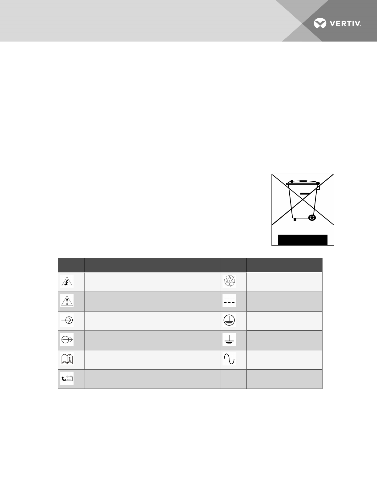
NOTICE TO EUROPEAN UNION CUSTOMERS: DISPOSAL OF OLD APPLIANCES—This product has been
supplied from an environmentally aware manufacturer that complies with the Waste Electrical and
Electronic Equipment (WEEE) Directive 2002/96/CE.
The “crossed-out wheelie bin” symbol at right is placed on this product to encourage you to recycle
wherever possible. Please be environmentally responsible and recycle this product through your
recycling facility at its end of life. Do not dispose of this product as unsorted municipal waste. Follow local
municipal waste ordinances for proper disposal provisions to reduce the environmental impact of waste
electrical and electronic equipment (WEEE). C
For information regarding the scrapping of this equipment, please browse
https://www.vertivco.com/en-emea/ or call our worldwide technical support.
• Toll Free: 00 80011554499
• Toll Number Based in Italy: +39 0298250222
Table 1.1 Glossary of Symbols
SYMBOL DESCRIPTION SYMBOL DESCRIPTION
Risk of electrical shock Recycle
Indicates caution followed by important instructions DC voltage
AC input Equipment grounding conductor
AC output Bonded to ground
Requests the user to consult the manual AC voltage
Indicates the unit contains a valve-regulated leadacid battery
1 Important Safety Precautions
7

This page intentionally left blank
8
Vertiv | Liebert® GXT4™Installer/User Guide
2 GXT4 DESCRIPTION
The Liebert® GXT4 is a compact, online uninterruptible power system (UPS) that continuously conditions
and regulates its output voltage. The Liebert® GXT4 supplies microcomputers and other sensitive
equipment with clean sine-wave input power.
Upon generation, AC power is clean and stable. However, during transmission and distribution it is subject
to voltage sags, spikes, and complete failure that may interrupt computer operations, cause data loss, and
damage equipment.
The Liebert® GXT4 protects equipment from these disturbances. The Liebert® GXT4 continuously
charges its batteries from the utility power, enabling it to supply power to connected loads, even when the
mains fail.
2.1 Features
• Intelligent battery management to extend the battery life
• LCD for user-friendly operation and local monitoring and configuration of operational
parameters
• Controllable outlet groups
• Fan fault self-inspection and automated diagnostic function
• Intelligent fan operation, automatically changing rotation speed depending on system
requirements, to decrease power consumption and noise
• Input circuit breaker to ease recovery from overloads
• Safety approval from UL and cUL
• Communication options: USB port, Liebert® IntelliSlot™ port and terminal-block communication
• Dry contacts for remote monitoring
• Input power factor greater than0.99
• Output voltage selection function
2.2 Available Models
Available models of the UPS are listed in the following table.
2 GXT4 Description
Table 2.1 UPS models, power ratings
MODEL NU MBER NOMINAL POWER RATING
GXT4-500RT120 500 VA/450 W
GXT4-700RT120 700 VA/630 W
GXT4-1000RT120 1000 VA/900 W
GXT4-1500RT120 1500 VA/1350 W
GXT4-2000RT120 2000 VA/1800 W
GXT4-3000RT120 3000 VA/2700 W
GXT4-3000RT208 3000 VA/2700 W
9
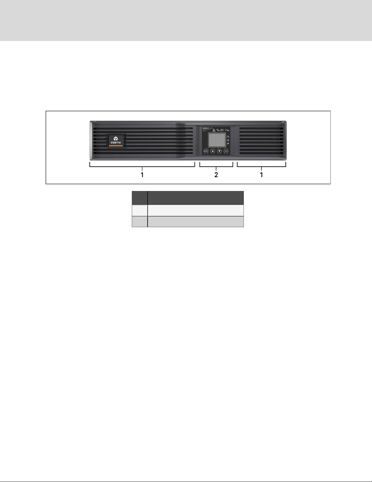
2.3 Front Panel and Controls
The Liebert GXT4 rack/tower models in various power ratings have the same general appearance,
controls and features as shown in the following figure. The various rack/tower and minitower models differ
largely in the type of receptacles each has.
Figure 2.1 Front view
NO. DESCRIPTION
1 Ventilation slots
2 Operation anddisplaypanel
2.4 Rear Panel Features
The rear panel of the Liebert® GXT4 has these features:
• Liebert® IntelliSlot™ Port
• USB port
• Input Circuit Breaker
• Input Receptacle
• General Output Receptacles
• Programmable Output Receptacles
• Cable Strain-relief Attachment Hole
• External Battery Connector
• Cooling Fan
• RS-232 port
• Terminal Block Communication
• Output Circuit Breakers (only on 3000VA models)
10
Vertiv | Liebert® GXT4™Installer/User Guide
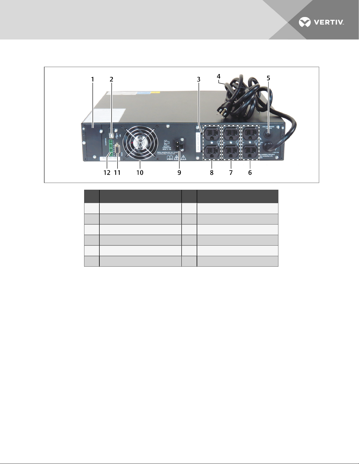
Figure 2.2 Rear panel components—120-V rack/tower, 500, 700, 1000VA models
NO. DESCRIPTION NO. DESCRIPTION
1 Liebert® IntelliSlot port 7 Programmable output receptacles #1
2 USB port 8 Generaloutput receptacles
3 Strain-relief attachment 9 External battery connector
4 Input pow er cable 10 Coolingfan
5 Input circuit breaker 11 RS232 port
6 Programmable output receptacles #2 12 Terminal block communication
2 GXT4 Description
11
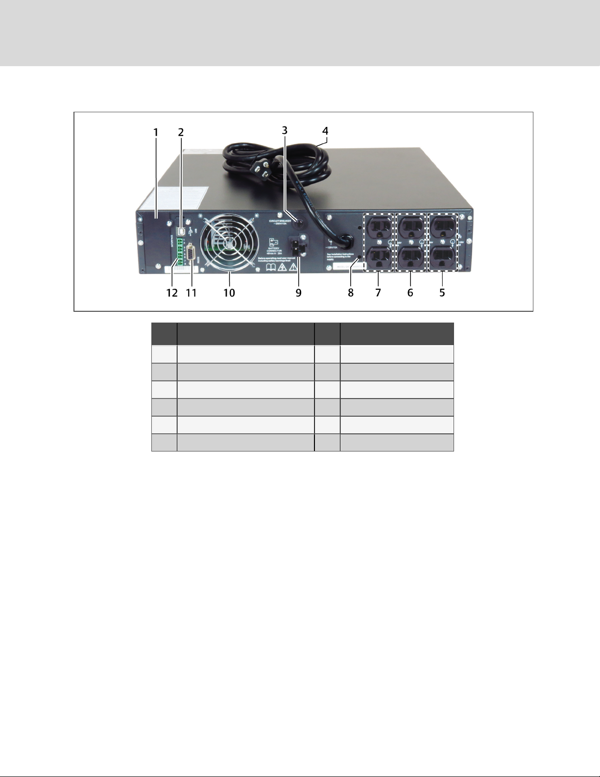
Figure 2.3 Rear panel components—120-V rack/tower, 1500VA
NO. DESCRIPTION NO. DESCRIPTION
1 Liebert® IntelliSlot port 7 Generaloutput receptacles
2 USB port 8 Strain-relief attachment
3 Input circuit breaker 9 External battery connector
4 Input pow er cable 10 Coolingfan
5 Programmable output receptacles #2 11 RS-232 port
6 Programmable output receptacles #1 12 Terminal block communication
12
Vertiv | Liebert® GXT4™Installer/User Guide
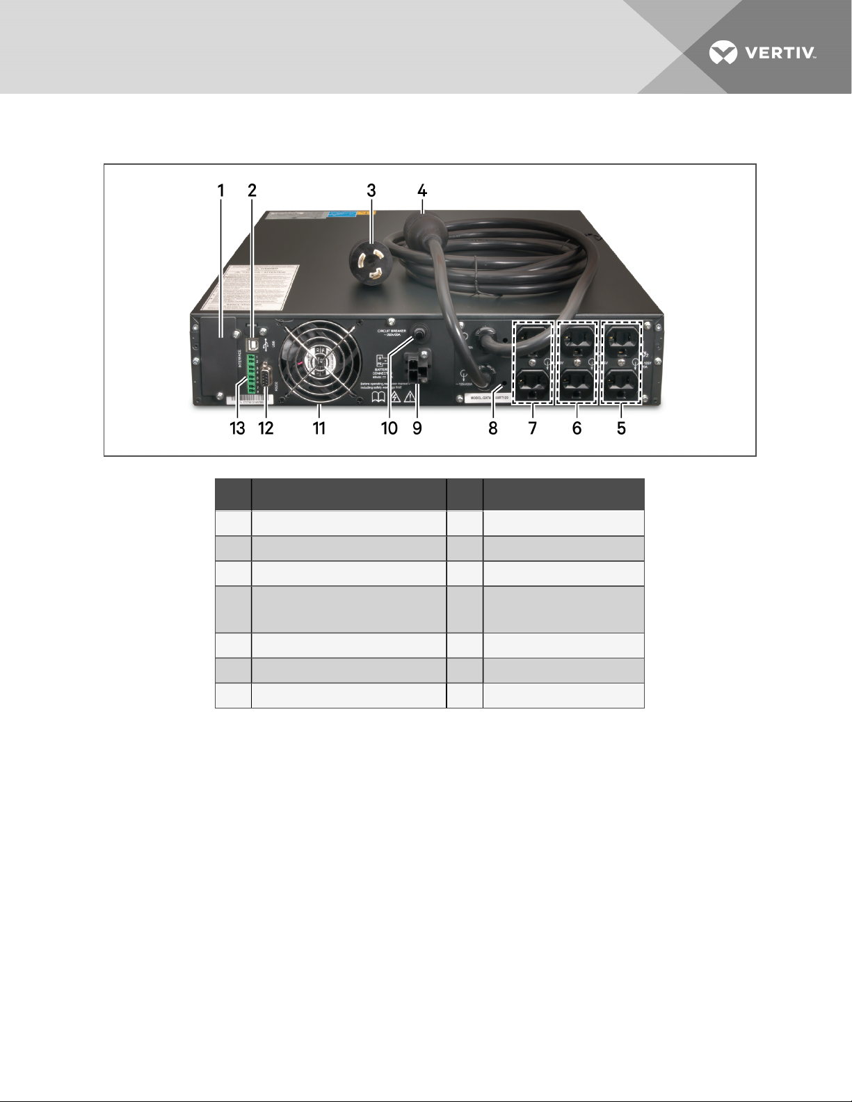
Figure 2.4 Rear panel components—120-V rack/tower, 2000VA models
NO. DESCRIPTION NO. DESCRIPTION
1 Liebert® IntelliSlot port 8 Strain-reliefattachment
2 USB port 9 External battery c onnec tor
3 Input power cable 10 Input circuit breaker
Output receptacle (L5-20R)
4
Not shown: 5-20P to L5-20R adapter
11 Cooling fan
5 Programmable output receptacles #2 12 RS232 port
6 Programmable output receptacles #1 13 Terminalblock communication
7 General output receptacles
2 GXT4 Description
13
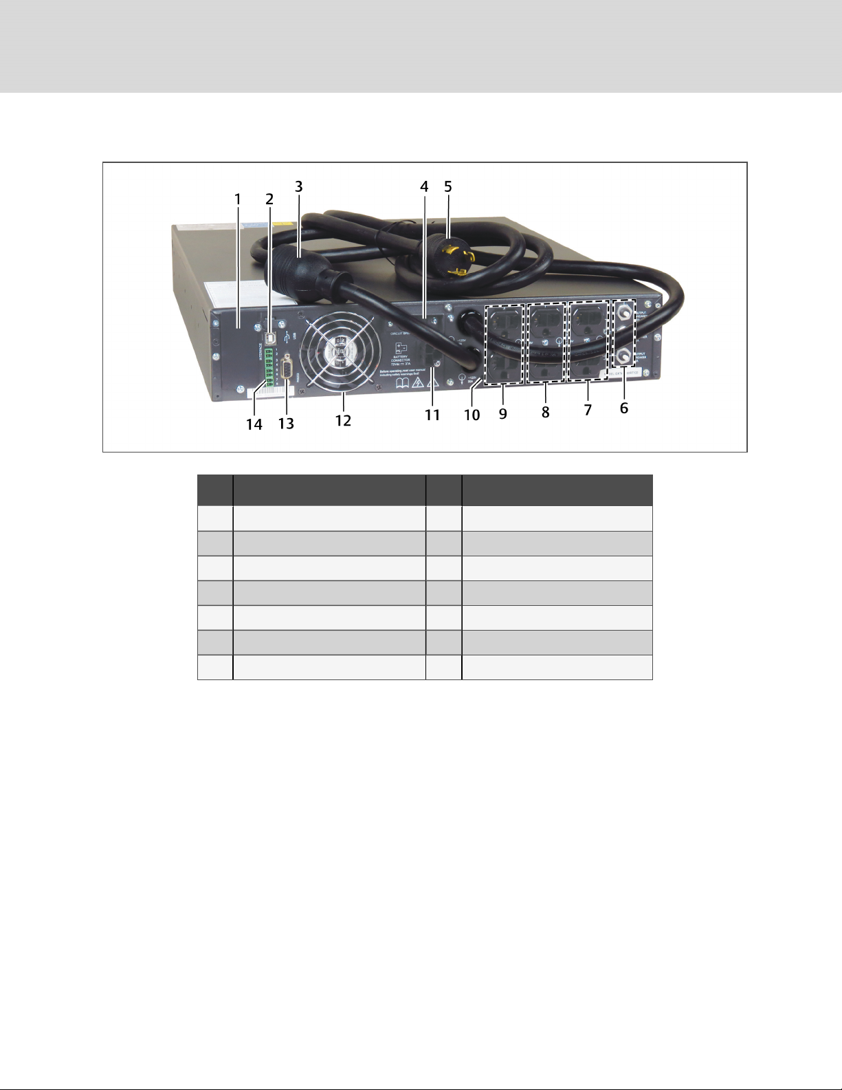
Figure 2.5 Rear panel components—120-V rack/tower, 3000VA
NO. DESCRIPTION NO. DESCRIPTION
1 Liebert® IntelliSlot port 8 Programmable output receptacles #1
2 USB port 9 General output receptacles
3 Output 10 Strain-reliefattachments
4 Input circuit breaker 11 Externalbattery connector
5 Input power plug and cable 12 Coolingfan
6 Output circuit breakers 13 RS-232 port
7 Programmable output receptacles #2 14 Terminal block communication
14
Vertiv | Liebert® GXT4™Installer/User Guide
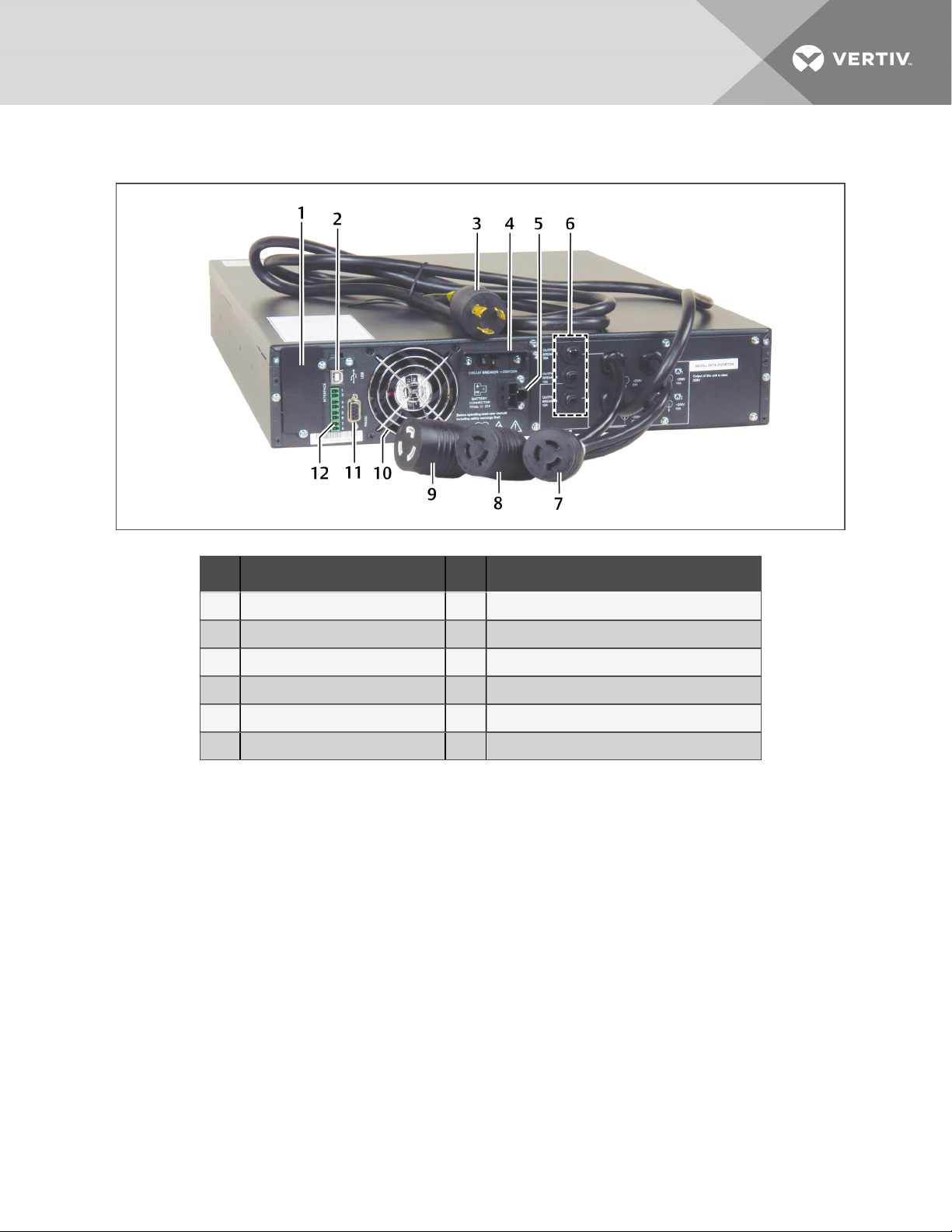
Figure 2.6 Rear panel components—208-V rack/tower, 3000VA
NO. DESCRIPTION NO. DESCRIPTION
1 Liebert® IntelliSlot port 7 Programmable output receptacle 1, L6-15R
2 USB port 8 Programmable output receptacle 2, L6-15R
3 Input power plug and cable, L6-20P 9 Non-programmable output receptacle 1, L6-20R
4 Input circuit breaker 10 Coolingfan
5 External battery connector 11 RS232 port
6 Output circuit breakers 12 Terminal block communication
2.5 Major Components
The UPS is composed of utility input, TVSS and EMI/RFI filters, rectifier/PFC, inverter, battery charger, DCto-DC converter, battery, dynamic bypass and UPS output.
NOTE: Only the GXT4-3000RT208 model (208 V) requires L2 (L6-20P). All other models covered in the
manual are 120-V L-N wired.
2 GXT4 Description
15
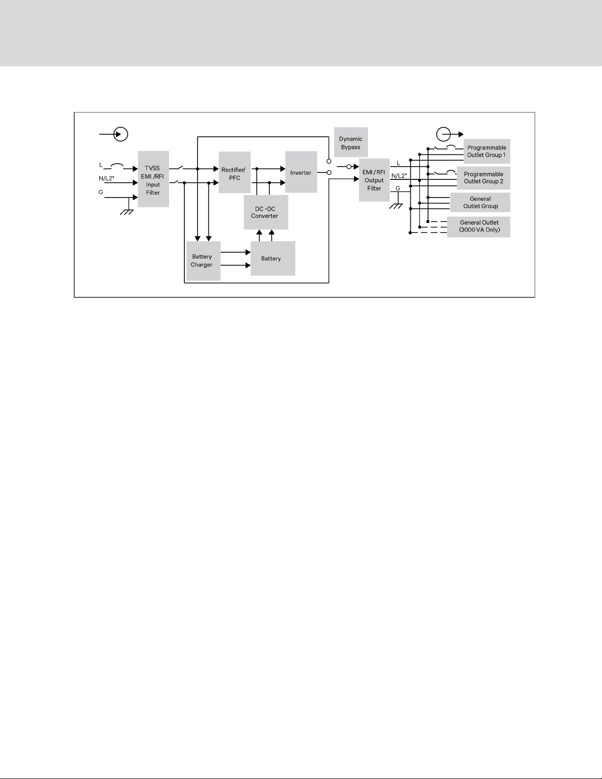
Figure 2.7 Operating principle diagram
2.5.1 Transient Voltage Surge Suppression (TVSS) andEMI/RFIFilters
The UPS has surge protection and filters that protect the connected load from power surges,
electromagnetic interference (EMI) and radio frequency interference (RFI). These features can minimize
any surges or interference present in the utility power. The filters also prevent surges or interference
generated by the UPS from adversely affecting devices connected on the same branch as the UPS.
2.5.2 Rectifier/Power Factor Correction (PFC) Circuit
In normal operation, the rectifier/PFC circuit converts utility power to regulated DC power for use by the
inverter while ensuring that the wave shape of the input current used by the UPS is near ideal. Extracting
this sine-wave input current achieves two objectives:
• Efficient power use by the UPS
• Reduced reflected harmonics
This results in cleaner power available to other devices in the building that are not protected by the
GXT4.
2.5.3 Inverter
In normal operation, the inverter utilizes the DC output of the PFC circuit to produce precise, regulated
sine-wave AC power. When utility power fails, the inverter receives DC power from the DC-to-DC
Converter. In either operation mode, the UPS inverter is online, continuously generating clean, precise,
regulated AC output power.
2.5.4 Battery Charger
The battery charger utilizes energy from the utility power and precisely regulates it to continuously float
charge the batteries. The batteries are being charged whenever the GXT4 is plugged in, even when the
UPS is not turned On.
16
Vertiv | Liebert® GXT4™Installer/User Guide

2.5.5 DC-to-DC Converter
The DC-to-DC converter raises the DC voltage from the battery to the optimum operating voltage for the
inverter. This allows the inverter to operate continuously at its optimum efficiency and voltage, thus
increasing reliability.
2.5.6 Battery
The GXT4 uses valve-regulated, non-spillable, lead acid batteries. To maintain battery design life, Operate
the GXT4 in an ambient temperature of 32°F to 77°F (0°C to 25°C).
Optional external battery cabinets are available to extend battery run times.
2.5.7 Dynamic Bypass
The GXT4 provides an alternate path for utility power to the connected loads in the unlikely event of a
UPS malfunction. Should the GXT4 have an overload, over-temperature or UPS failure condition, the UPS
automatically transfers the connected loads to bypass.
NOTE: The bypass power path does not protect the connected loads from disturbances on the utility.
2.5.8 Battery Cabinet
Optional battery cabinets are available for the Liebert® GXT4, shown in Battery cabinet on the next
page.The battery connectors and input breaker are on the battery cabinet’s rear panel, as shown in the
figure. For battery cabinet specifications, refer to Specifications on page53. The GXT4 may be equipped
with a maximum of 6 extension battery packs.
For battery run times, refer to Battery run times (continued) on page60.
WARNING! Do not contact the battery connectors and ground to avoid electrical shock. The
battery loop and AC input are not insulated, which may cause a dangerous voltage between the
battery connectors and ground.
NOTE: External Battery Connectors are wired in parallel. Either connector can be connected to the UPS
or to another battery cabinet.
NOTE: The standard battery cable delivered with the battery cabinet is 0.65m (2.13ft) long.
2 GXT4 Description
17
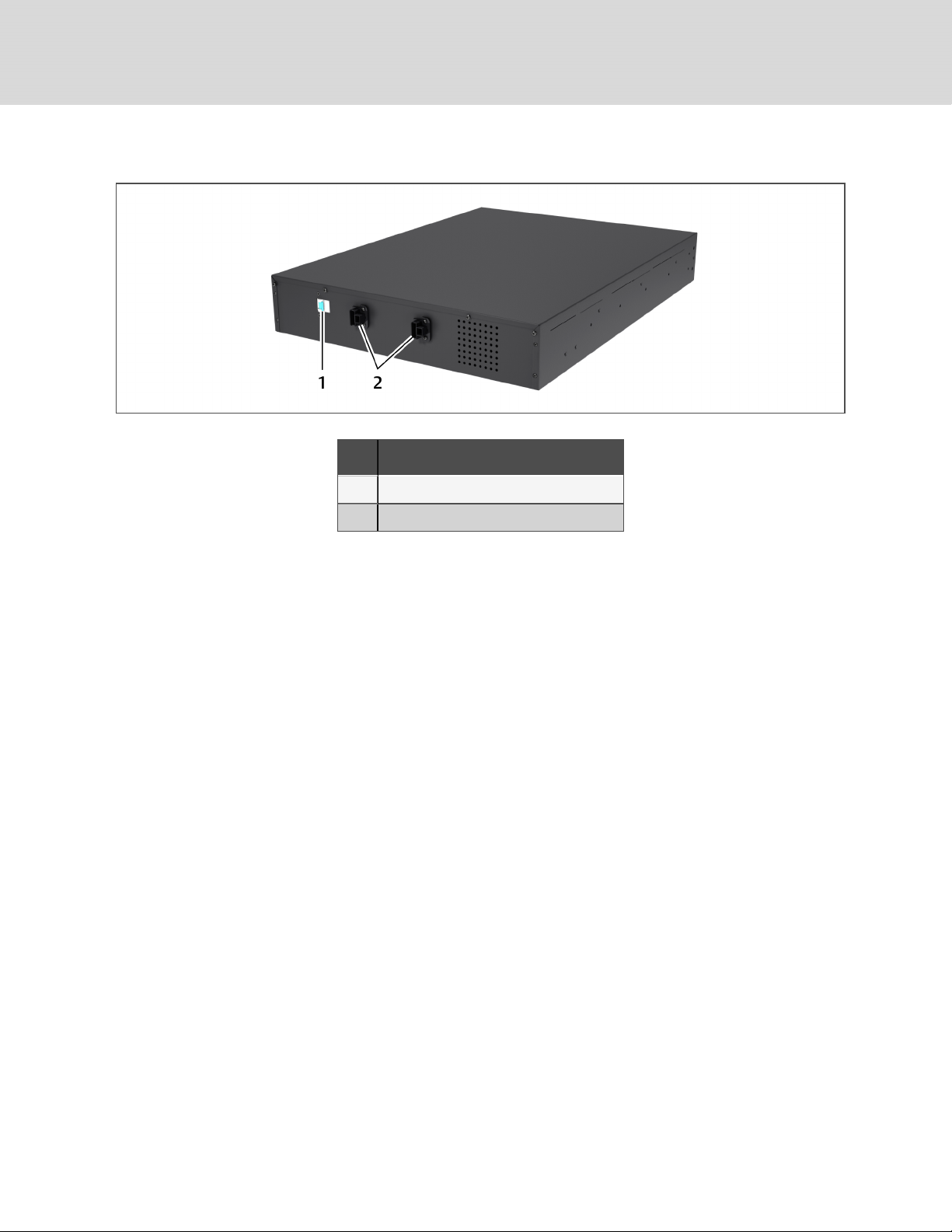
Figure 2.8 Battery cabinet
NO. DESCRIPTION
1 Isolation breaker
2 Battery connectors
2.6 Operating Modes
The UPS operation modes include the following: Mains (AC) Mode, Bypass Mode, Battery Mode, Battery
Recharge Mode, Active ECO Mode and Frequency Converter Mode.
Refer to Operation and Display Panel on page27 for details about the operating mode indicators and
control buttons.
2.6.1 Mains Mode
During Mains Mode, the mains provides input power to the GXT4. The filters, PFC circuit and inverter
process this power to provide high-quality sine wave power to connected loads. The UPS maintains the
batteries in a fully-charged state.
2.6.2 Manual Bypass Mode
Manual Bypass Mode occurs when the unit is manually placed in internal bypass by navigating the LCD
menu to select 3 Control > 1 Turn On & Off > Turn UPS Bypass. Bypass operation is indicated by an audible
alarm and illuminated amber bypass indicator. (If other indicators are illuminated, refer to
Troubleshooting on page49). During Bypass Mode, mains power bypasses the inverter and provides
energy to the connected load.
NOTICE
Risk of loss of power to the connected load. Can cause equipment damage.
Turning Off the UPS in Bypass Mode will result in loss of output power to the connected load.
18
Vertiv | Liebert® GXT4™Installer/User Guide

2.6.3 Battery Mode
The GXT4 enters Battery Mode when mains power fails or is outside acceptable limits. The battery system
supplies power through the DC-to-DC converter to the inverter to generate clean AC power for the
connected loads.
When the GXT4 enters Battery Mode, the UPS sounds a half-second beep at 10-second intervals. When
approximately 2 minutes of run time remains, the beeps sound every 5seconds to warn that the battery is
getting low (this Low Battery Warning is user-configurable).
In Battery Mode, the battery indicator will illuminate and the LCD will show the prompt utility power not
available.
Press either the Up or Down button once, then press the Enter button to clear the prompt and silence the
audible alarm. Once the alarm prompt has been acknowledged, the screen showing the estimated battery
run time and battery capacity will be visible. Refer to Troubleshooting on page49.
For approximate battery run times, refer to Table 9.5 on page60.
NOTICE
Risk of loss of power to the connected load. Can cause equipment damage.
Turning Off the GXT4 when it is in Battery Mode will result in loss of output power to the
connected load.
If the UPS is turned Off manually, it must be manually restarted after mains power returns.
If the UPS is turned Off by a communication signal or because the batteries are depleted, it will
operate as set in the configuration program for Auto-Restart (Refer to Configuration Program
on page39).
2.6.4 Battery Recharge Mode
Once mains power is applied to the GXT4, the Battery Charger begins charging the batteries.
2.6.5 Frequency Converter Mode
All models of the GXT4 are capable of frequency conversion. Frequency Conversion Mode can be selected
using the configuration program. Allowable frequency operating modes include:
• Auto Sensing - 50 Hz or 60Hz – Bypass Enabled
• Auto Sensing - 50 Hz or 60Hz – Bypass Disabled
• Frequency Converter - 50 Hz – Bypass Disabled
• Frequency Converter - 60Hz – Bypass Disabled
NOTE: The default for all models of the Liebert® GXT4 is “Auto Sensing - 50 Hz or 60Hz – Bypass
Enabled.”
2.6.6 Active ECO Mode
All Liebert® GXT4 models can operate in Active ECO Mode. In this mode, the connected equipment is
powered through the bypass path to increase efficiency, reducing the electrical costs.
2 GXT4 Description
19

Active ECO mode keeps the rectifier and inverter operating, allowing the inverter to remain synchronized
to bypass. This synchronization allows the transfer of the connected equipment to UPS inverter power
almost seamlessly if bypass power falls outside the user-set limits. Once bypass power returns within the
acceptable parameters, the UPS will return to Active ECO Mode operation.
The default setting is Active ECO Mode Off.
20
Vertiv | Liebert® GXT4™Installer/User Guide
 Loading...