

Vertiv EXS 0010kTH1AFN01, Liebert EXS 20kVA, EXS 0015kTH1AFN01, EXS 0010kTH1AFN02, EXS 0020kTH1AFN01 User Manual
...
Liebert® EXS 10-20kVA
User Manual

EXS 10-20kVA
UNINTERRUPTIBLE POWER SUPPLY
USER MA
10H52260UM60 – rev. 1
NUAL

EXS
y
All rights, including rights of translation, reproduction in any
form or other usage of this document, or any part of it, are
reserved.
Transgressors will be liable for damages.
All rights, including rights deriving from the granting of
patent or registration of utility, model or design, are
reserved.
Delivery subject to availability. The Manufacturer reserves
the right to make changes and/or improvements to the
product without prior notice and without incurring
obligations.
EXS ma
2 User Manual 10H52260UM60 - Rev. 1 - 10/2017
differ from the model displayed on the front cover.

EXS
Special Declaration
Safety of Personnel
1. This product must be installed by qualified professionals, engineers appointed by the manufacturer or an
authoriz
personnel.
2.Take the time to read this product manual and the safety precautions thoroughly before inst
commissioni
the safety of personnel.
3. This product is not intended for use with life support system
4. Ne
inju
Product Safety
ed agent. Failure to observe this condition may result in product malfunction, and compromise the safety of
ng this product. Failure to observe this condition may result in product malfunction, and compromise
ver attempt to dispose of the internal and external batteries in fire as they may explode, leading to seri
ries, or even death.
alling and
s
ous
1. If the product is to be stored or unused for extended periods, place the equipment in a clean, dry environment
within the specified temper
2. This product should be used in an appropriate operating environment. Consult the Site Preparation section for
ormation about the ideal operating and maintenance environment for this product
inf
3. This product is not designed for use in conditions and/or environments where:
The temperature and relative humidity are outside the specified limits
It is subject to vibration or shocks
It is exposed to the presence of conductive dust, corrosive gases, salts, or inflammable gases
It is exposed to heat sources or strong electro-magnetic interference
Disclaimer
VERTIV may not be held accountable or responsible for defects and malfunctions arising for the following reasons:
Application range or operating environment outside the specified limits
Unauthorized modification, incorrect installation or operation
Force majeure
Other actions not in compliance with the instructions in this manual
ature range
User Manual 10H52260UM60 - Rev. 1 - 10/2017 3
EXS
Safety Precautions
Always observe the following safety symbols!
Used to alert the user to the risk of death or severe injury should the unit be used improperly.
Used to alert the user to the risk of injury or damage to the equipment should the unit be used improperly.
Used for instructions that the user must read carefully and observe, even if failure to do so may not result in damage.
This manual contains information concerning the installation and operation of single UPS modules and parallel
systems of the Vertiv EXS 10kVA-20kVA UPS.
Read this manual thoroughly before installing, using and servicing the UPS.
Warning
This UPS has been designed for use in commercial and industrial environments. Installation restrictions or additional measures
may be required to prevent disturbances.
Conformity and standards
This product complies with the Directives 2014/35/EU (low voltage safety) and 2014/30/EU (EMC), and the following UPS
product standards:
* IEC/EN62040-1+A1:2013 General safety requirements for UPS
* IEC/EN62040-2:2006 EMC
* IEC/EN62040-3 Performance requirements and test methods
For more details, refer to Chapter 10 .
Continued compliance requires installation in accordance with these instructions and the use of manufacturer approved
accessories only.
Warning: high earth leakage current
The unit must be connected to earth before it is connected to its AC mains input and battery power supplies.
This equipment is fitted with an EMC filter.
The earth leakage current ranges from 0 to 1000 mA.
Transient and steady state earth leakage currents, which may occur when the equipment is started, should be taken into
account when se4lecting the instantaneous RCCB or RCD devices.
RCCB devices that are sensitive to unidirectional DC pulses (Class A) and immune to transient state current pulses must be
selected.
It is also necessary to take into account that the load earth leakage currents will be borne by the RCCB or RCD.
The equipment must be earthed in compliance with the local electrical code of practice.
Warning
When selecting the UPS system upstream distribution protection devices, ensure that comply with the specifications
indicated in 3.1.4 , and with the local electrical regulations.
Warning: backfeed protection
This UPS is fitted with a dry contact for use with an external automatic disconnecting device (not supplied) in order to prevent
the UPS voltage from being fed back to the input terminals through the rectifier or bypass static switch circuit. A label must be
placed on or near the all external primary input supply disconnecting devices to warn service personnel that the circuit is
connected to a UPS. The text of the label must have the following meaning: Risk of voltage backfeed! Isolate the UPS, then
check for hazardous voltages between all terminals, including the protective earth, before working on this circuit.
4 User Manual 10H52260UM60 - Rev. 1 - 10/2017
EXS
ral safety precautions (For users)
Gene
Like other types of large power equipment, the UPS and battery circuit breaker box/battery cabinet contain high voltages.
This equipment meets the IP20 standard, and other safety panels are fitted inside the equipment.
The UPS may be operated in complete safety, provided the general instructions and the steps recommended in this manual
are followed.
Multip
le power inputs (For users)
This UPS system receives power from more than one source. All DC and AC power sources must be disconnected before
servicing.
This UPS includes several circuits that are energized by high AC as well as DC voltages. Check for voltage with both AC and
DC voltmeters before working inside the UPS.
User serviceable compon
All equipment maintenance and servicing procedures involving internal access require the use of a tool and should be carried
out by trained personnel only. There are no user-serviceable parts behind the covers that require a /key for removal.
Batt
ery voltage: 320Vdc - 540Vdc (For service personnel)
All battery maintenance and servicing procedures require the use of tools and should be carried out by trained personnel only.
Take special care when working with the batteries associated with this UPS. When connected together, the battery terminal
voltage will exceed 320Vdc and is potentially lethal.
Battery manufacturers supply details of the necessary precautions to be observed when working on, or in the vicinity of, a
large bank of battery cells. These precautions should be followed scrupulously at all times. Special attention should be paid to
the recommendations concerning local environmental conditions and the provision of protective clothing, first aid and fire-
fighting facilities.
Warning
When the internal fuse of the UPS is damaged, it must be replaced with fuse having the same electric parameters by qualified
personnel.
Important
The area housing the communication board contains static sensitive components, therefore it is necessary to adopt all the
appropriate ESD-proof measures before accessing this area.
ents (For service personnel)
Warning
In order to satisfy the conditional short circuit current rating, Icc at 10kA symmetrical rms, the specified upstream breakers
must comply with an IEC 60947 series standard.
User Manual 10H52260UM60 - Rev. 1 - 10/2017 5

This Manual describes the following devices
Product Model
Liebert EXS 10kVA (Standrad UPS) EXS 0010kTH1AFN01
Liebert EXS 15kVA (Standard UPS) EXS 0015kTH1AFN01
Liebert EXS 20kVA (Standard UPS) EXS 0020kTH1AFN01
Liebert EXS 10kVA (UPS with side cabinet) EXS 0010kTH1AFN02
Liebert EXS 15kVA (UPS with side cabinet) EXS 0015kTH1AFN02
Liebert EXS 20kVA (UPS with side cabinet) EXS 0020kTH1AFN02
EXS
6 User Manual 10H52260UM60 - Rev. 1 - 10/2017

EXS
Contents
Chapter 1 Overview ......................................................................................................................................................................................................... 9
1.1 Features .......................................................................................................................................................................................................................................................................... 9
1.2 Design Conce
1.3 Parallel System ......................................................................................................................................................................................................................................................... 12
1.4 Operating Modes .................................................................................................................................................................................................................................................... 13
1.5 Battery Management
1.6 Battery Pro
pt ......................................................................................................................................................................................................................................................... 9
............................................................................................................................................................................................................................................ 15
tection .................................................................................................................................................................................................................................................. 16
Chapter 2 Mechanical Installation ............................................................................................................................................................................ 1
2.1 Precautions
2.2 Transportation ......................................................................................................................................................................................................................................................... 17
2.3 Tools .............................................................................................................................................................................................................................................................................. 18
2.4 Unpacking .................................................................................................................................................................................................................................................................. 19
2.5 Initial Inspection ..................................................................................................................................................................................................................................................... 21
2.6 Environmental Requirements
2.7 Mechanical Requirements
2.8 Installation Drawings .......................................................................................................................................................................................................................................... 23
Chapter 3 Electrical Installatio n ............................................................................................................................................................................... 2
3.1 Connecting the Power Ca
3.2 Wiring the Signal Cables .................................................................................................................................................................................................................................... 31
Chapter 4 Operator Control and Dis play Panel ................................................................................................................................................... 35
4.1 Introduction .............................................................................................................................................................................................................................................................. 35
4.2 LCD Menu Structure
4.3 LCD Screen Types .............................................................................................................................................................................................................................................. 40
4.4 Prompt Window ..................................................................................................................................................................................................................................................... 46
4.5 UPS Alarm Messa
................................................................................................................................................................................................................................................................ 17
......................................................................................................................................................................................................................... 21
................................................................................................................................................................................................................................ 22
bles ........................................................................................................................................................................................................................ 25
.......................................................................................................................................................................................................................................... 40
ge List .................................................................................................................................................................................................................................. 46
7
5
Chapter 5 Oper ating Procedure s ............................................................................................................................................................................. 5
5.1 Brief Introduction ................................................................................................................................................................................................................................................... 50
5.2 UPS Start-up Procedures
5.3 Procedures for Transferring Between Opera
5.4 UPS Shut-down Procedures ........................................................................................................................................................................................................................... 58
5.5 REPO ............................................................................................................................................................................................................................................................................ 58
5.6 Automatic Re
5.7 Language Selection ............................................................................................................................................................................................................................................. 59
5.8 Changing the Current Da
5.9 Setting the Password .......................................................................................................................................................................................................................................... 61
Chapter 6 Battery ......................................................................................................................................................................................................... 6
6.1 Introduction .............................................................................................................................................................................................................................................................. 65
6.2 Safety ........................................................................................................................................................................................................................................................................... 65
6.3 UPS Ba
6.4 Precautions For Installation Design ........................................................................................................................................................................................................... 68
6.5 Battery Installation Environment a
6.6 Battery Pro
User Manual 10H52260UM60 - Rev. 1 - 10/2017 7
start ................................................................................................................................................................................................................................................ 59
ttery .............................................................................................................................................................................................................................................................. 67
tection ................................................................................................................................................................................................................................................ 69
.................................................................................................................................................................................................................................. 51
ting Modes............................................................................................................................................................... 54
te And Time ..................................................................................................................................................................................................... 60
nd Number of Batteries ......................................................................................................................................................... 68
0
5

6.7 Battery Installation and Connections ........................................................................................................................................................................................................ 69
6.8 Designing the Battery Room .......................................................................................................................................................................................................................... 70
6.9 Battery Maintena
6.10 Disconnecting or Connecting Internal Battery Terminals ........................................................................................................................................................... 71
6.11 Disposal of Used Batteries ............................................................................................................................................................................................................................. 72
Chapter 7 Para llel System and LBS System .......................................................................................................................................................... 7 3
7.1 General ......................................................................................................................................................................................................................................................................... 73
7.2 System Installation Procedures
7.3 Operating Procedures for Parallel Systems ........................................................................................................................................................................................... 75
7.4 LBS System .............................................................................................................................................................................................................................................................. 78
nce .......................................................................................................................................................................................................................................... 70
.................................................................................................................................................................................................................... 73
EXS
Chapter 8 Opti ons ......................................................................................................................................................................................................... 8
8.1 List of Options ......................................................................................................................................................................................................................................................... 82
8.2 Option Introduction ............................................................................................................................................................................................................................................. 82
Chapter 9 Service And Maintena nce ...................................................................................................................................................................... 9
9.1 Fan Maintenance ................................................................................................................................................................................................................................................... 98
9.2 Battery Maint
9.3 Cleaning the UPS .................................................................................................................................................................................................................................................. 99
9.4 Checking the UPS Status ................................................................................................................................................................................................................................. 99
9.5 Checking the UPS Functions ......................................................................................................................................................................................................................... 99
Chapter 10 Specifications ........................................................................................................................................................................................ 100
10.1 Conformity and sta
10.2 Environmental Characteristics................................................................................................................................................................................................................. 100
10.3 Mechanical Specifications .......................................................................................................................................................................................................................... 100
10.4 Electrical Specifications (Inpu
10.5 Electrical Specifications (Intermediate DC Circuit) ....................................................................................................................................................................... 101
10.6 Electrical Specifications (Inverter Output) ........................................................................................................................................................................................ 102
10.7 Electrical Specifications (Bypass Input) .............................................................................................................................................................................................. 102
Appendix 1 LCD Parameter Settings .................................................................................................................................................................... 103
enance .......................................................................................................................................................................................................................................... 98
ndards .......................................................................................................................................................................................................................... 100
t Rectifier) ............................................................................................................................................................................................ 101
2
8
Appendix 2 Glossary .................................................................................................................................................................................................. 1
Appendix 3 Haz ardous Substances And Content ............................................................................................................................................ 106
8 User Manual 10H52260UM60 - Rev. 1 - 10/2017
05

EXS
Chapter 1 Overview
This section provides a short introduction to the Liebert EXS 10kVA - 20kVA UPS (hereafter referred to as “the
UPS”), covering features, design concept, parallel system, operating mode, battery management and battery
protection.
1.1 Features
The UPS is connected between a critical load (e.g. a computer) and the mains power supply to provide high quality
power for the loads. The UPS provides the following advantages:
Increased power quality
The UPS protects its output against the variations in the input power supply by means of the intelligent controller.
Improved noise rejection
Due to the use of AC-DC-AC conversion, noise on the input power supply is effectively filtered, so that the load is
provided with a “clean” power supply.
Mains failure protection
If the input power fails, the UPS switches to battery operating mode so that the power supply to the loads is not
interrupted.
Compatible with two output modes
3-in 3-out (factory default) and 3-in 1-out (by installing an optional 3-in 1-out copper bar kit). Only authorized
personnel are permitted to change the wiring method and modify the corresponding parameters using the VERTIV
setting software.
1.2 Design Concept
System Design
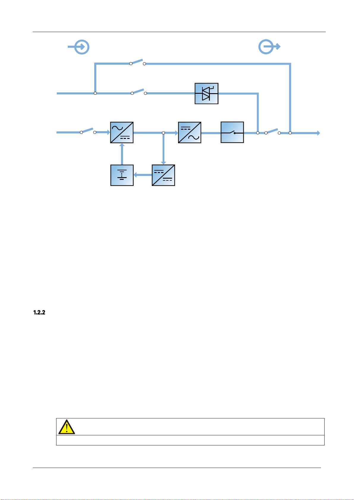
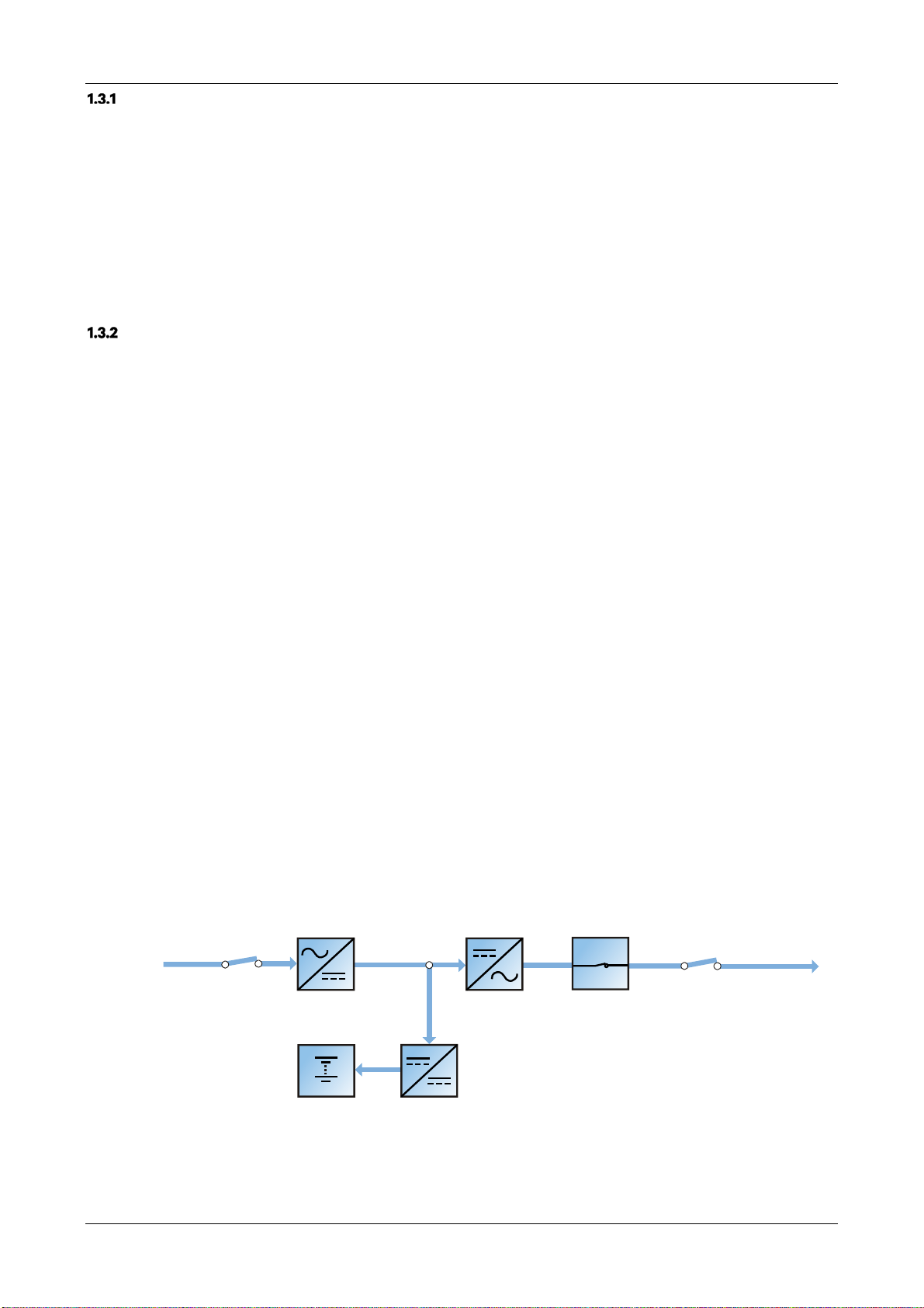
This section introduces the working principle of the single UPS module. The UPS adopts AC-DC-AC conversion (as
shown in Figure 1-1). The first stage conversion (AC-DC) uses a three-phase, high frequency rectifier to convert the
three-phase input voltage into a stable DC bus voltage.
User Manual 10H52260UM60 - Rev. 1 - 10/2017 9
EXS
Input
Output
Bypass input
Mains input
Rectifier input switch
Maintenance bypass switch
Static switch
Bypass input switch
Rectifier
Battery
Figure 1-1 Block diagram illustrating the working principle of a UPS single module
Battery charger
Inverter
Automatic inverter switch
Maintenance bypass
UPS output
Output switch
The UPS has its own battery charger and adopts advanced temperature compensation technology to effectively
prolong the battery service life. The inverter is principally based on the use of large power IGBTs, and adopts
advanced SVPWM control technology to reconvert the DC bus voltage to AC voltage.
When the mains is normal, the rectifier and inverter work together to supply the loads and charge the battery.
When the mains is outside normal limits, the rectifier stops working, and the battery supplies power to the loads
through the inverter. If the battery voltage falls to end of discharge (EOD) voltage and the mains has not yet
returned within the normal limits, the UPS will shut down (if the system uses split bypass configuration and the
bypass is normal, the system will transfer to bypass). The battery EOD voltage is pre-set. When the mains is
abnormal, the battery will continue to supply the UPS until the battery voltage reaches to EOD level, whereupon the
UPS shuts down; this period is known as the 'Backup Time'. The duration of the backup time depends on the battery
capacity and the loads.
Bypass
Thanks to the intelligent control function provided by the ‘Static Switch’ module (as shown in Figure 1-1), which
includes the controllable electronic switch, the loads may be supplied either by the inverter or the bypass. Under
normal operating conditions, the loads are supplied by the inverter, in which case the automatic inverter switch on
the inverter side is closed. In the event of an overload (after the overload delay period has elapsed) or inverter
failure, the inverter switch is opened, and the 'Static Switch' module transfers the loads automatically to the bypass.
In normal operating state, in order to guarantee the uninterrupted transfer between inverter and bypass, the inverter
output must be synchronized with the bypass.
Therefore, when the bypass frequency is within the synchronization range, the inverter control circuit will
synchronize the inverter output frequency with the bypass frequency and phase.
The UPS is also equipped with a manual maintenance bypass switch that can be used to shut the UPS down during
maintenance. In this condition, the bypass will supply the critical loads directly via the maintenance bypass.
Note
When the load is supplied by the bypass or maintenance bypass, the power quality & availability will be unregulated.
10 User Manual 10H52260UM60 - Rev. 1 - 10/2017

EXS
System Control Principle
Normal operation
Normal mode: In this condition, the UPS mains input supply is within normal limits, the rectifier and inverter operate
normally, the load is supplied by the inverter, the battery circuit breaker is closed, and the battery is in the stable
floating charge state.
(Parallel System) Note: As the individual UPS module outputs are connected in parallel, the system checks that the
inverter control circuits are perfectly synchronized with one another and with the bypass in terms of both frequency
and phase, and that the output voltages are the same. The current supplied to the load is automatically divided
among the UPS units. A warning message appears while synchronization is in progress.
Mains abnormal
When the mains fails or is abnormal, the rectifier will stop working automatically, and the system will transfer to
battery output (through the inverter). The length of the operation time in battery mode depends on the load and the
battery capacity. During this period, if the battery voltage falls to the EOD level before the mains supply has
returned within normal limits, the inverter will stop working automatically, and the UPS operator control and display
panel will display the corresponding alarm messages. If the system uses split bypass configuration and the bypass is
normal, the system will transfer to bypass.
Mains recovery
When the mains returns within normal limits within the permissible time, the rectifier will start automatically (at this
point its output power will increase gradually) and supply the load and charge the battery again. This means that
the power supply to the load will not be interrupted.
Disconnecting the battery
To disconnect the external battery from the UPS system during maintenance, use the external isolation device. In
this condition, the battery backup function will not be available in the event of a mains failure, but none of the other
UPS functions and performance will be affected.
UPS module failure
In the event of an inverter failure, automatic inverter switch failure, or if the output fuse blows, the load will
automatically transfer to the bypass, and the output power supply will not be interrupted. Should this condition
occur, please contact your local VERTIV customer service centre for technical support.
(Parallel System) In the event of a fault on a UPS module, it will automatically exit the parallel system. If the system
is still capable of providing the power required by the load, the remaining modules will continue to supply the load
without interruptions. If the remaining modules are no longer capable of fulfilling the power requirements, the load
will automatically transfer to the bypass.
Overload
If the inverter is overloaded or the inverter current remains outside the specifications (refer to Table 10-6) longer
than the specified time, the load will automatically transfer to the bypass without any interruption in the power
supply to the load. If both the overload and the current are reduced to a level within the specified range, then the
load will be re-transferred to the inverter. In the event of an output short circuit, the load will be transferred to the
bypass, and the inverter will shut down. The transfer is determined primarily by the characteristics of the system
protection device.
In both the situations listed above, the UPS operator control and display panel will display the corresponding alarm
messages.
(Parallel System) The control logic system constantly monitors load requirements and controls the power supplied
by each UPS module. If an overload condition persists for longer than a pre-set period and the number of active
modules is unable to satisfy load requirements, the load will transfer to the bypass. The load is re-transferred to the
inverter if the power is reduced to a value that can be sustained by the number of active modules in the system.
User Manual 10H52260UM60 - Rev. 1 - 10/2017 11
Maintenance bypass
The UPS is equipped with a second bypass circuit, known as the maintenance bypass, which provides a safe
working environment for the engineers to carry out regular maintenance or repair the UPS system, while providing
unregulated mains supply to the loads. The maintenance bypass can be activated manually selected by closing the
maintenance bypass switch, and disconnected by setting the switch to OFF.
Warning
If the UPS system consists of two or more UPS modules, and the load capacity exceeds the single module capacity, do not
use the internal maintenance bypass switch.
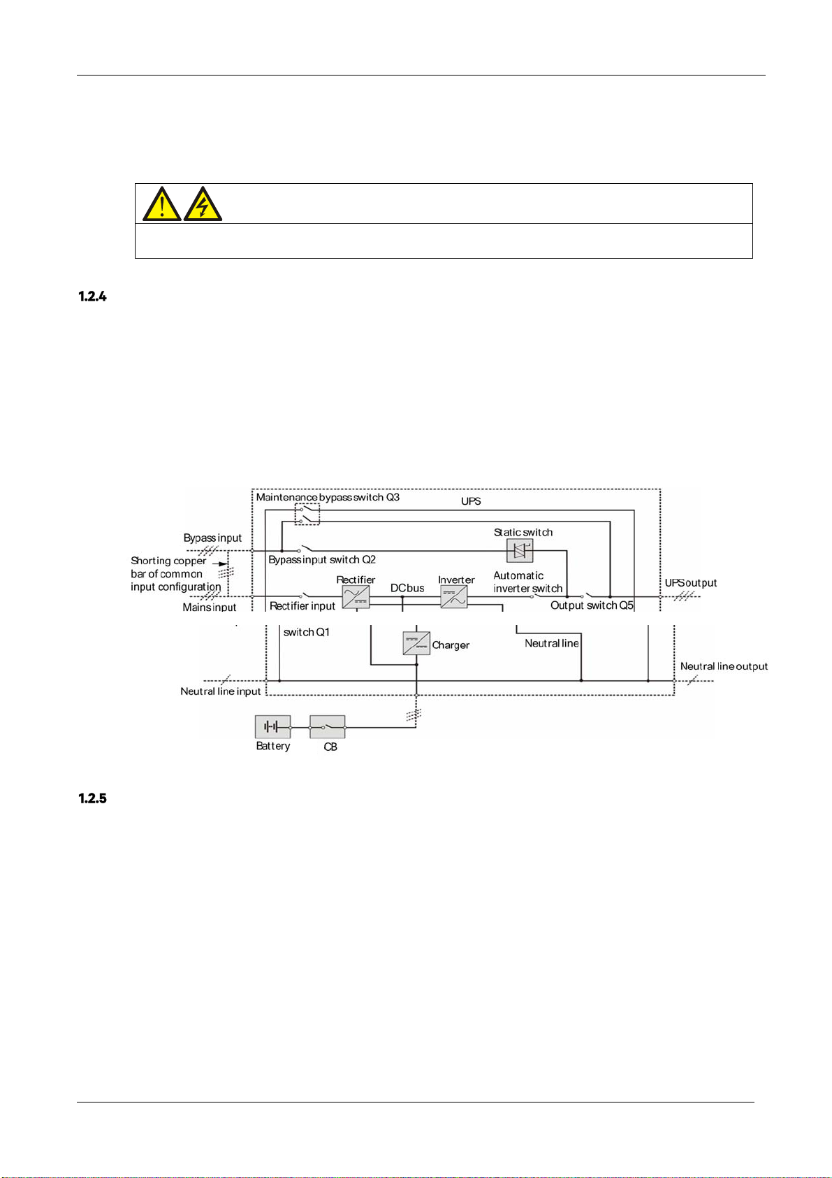
UPS Power Supply Switch Configuration
Figure 1-2 illustrates the block diagram of the UPS module. The UPS may be connected in split bypass (where the
bypass is supplied by a separate mains input source) or common input configuration. In the split bypass
configuration, the static bypass and maintenance bypass share the same independent bypass power supply. Where
a separate power source is not available, the input supply connections of the bypass input switch (Q2) and rectifier
input switch (Q1) should be linked together (these terminals are linked before delivery) so that the bypass input and
rectifier input use mains power from the same source.
During the normal UPS operation, all switches should be closed, with the exception of the maintenance bypass
switch Q3.
EXS
Figure 1-2 UPS power supply switch configuration
Circuit Breaker
The external battery shall be connected to the UPS via the circuit breaker.
1.3 Parallel System
Up to four UPS modules may be parallel-connected to form a parallel system and increase the system capacity and
reliability. The load is shared equally between the parallel connected UPS modules.
Also, two UPS modules or parallel system may be used to form a dual bus system (LBS). Each UPS module or
parallel system has an independent output. Output synchronization is achieved through the LBS cable, thus
enabling seamless load transfer between the two systems.
12 User Manual 10H52260UM60 - Rev. 1 - 10/2017
EXS
Parallel System Features
1. The hardware and software of a parallel system are identical to those of the individual modules. The parallel
system is configured by modifying the respective settings in the configuration software or via the control panel.
2. Parallel cables are connected in a ring, providing both system reliability and redundancy. LBS cables are
connected between any two UPS modules of each bus. The intelligent parallel logic provides the user with maximum
flexibility. For example, the UPS modules in a parallel system can be shut down or started up in any order. Transfers
between normal mode and bypass mode of operation are seamless and self-recoverable, i.e, when the overload is
cleared the system will revert automatically to its original operating mode.
3. The total load of the parallel system can be queried from the LCD screen on each UPS
Parallel System Requirements
A group of paralleled modules behave as if it were one large UPS with the advantage of providing increased
reliability. To ensure that all modules are utilised equally and to comply with relevant wiring rules, the following
requirements apply:
All UPS modules must be of the same rating and must be connected to the same bypass sour
1.
2.The bypass a
3.
If any RCD devices are installed they must be set-up appropriately and located upstream of the common neutra
line i
nput terminal. Alternatively, the device must monitor the protective earth current of the system. Refer to
nd rectifier input sources must be connected to the same neutral line input te
Warning: high earth leakage current before Contents.
module.
ce.
rminal.
l
1.4 Operating Modes
The UPS features the following operating modes:
Normal mode
Battery mode
Bypass mode
Maintenance mode
ECO mode
Parallel redundancy mode (system expansion)
LBS system mode
Common battery string mode
Normal mode
As shown in Figure 1-3, the mains is rectified by the UPS rectifier and then inverted by the inverter to supply
uninterrupted AC power to the loads. At the same time, the charger will charge the battery.
Mains input
Rectifier input switch
Rectifier
Inverter
Automatic inverter switch
UPS output
Output switch
Battery
User Manual 10H52260UM60 - Rev. 1 - 10/2017 13
Battery charger
Figure 1-3 Normal operating mode line diagram
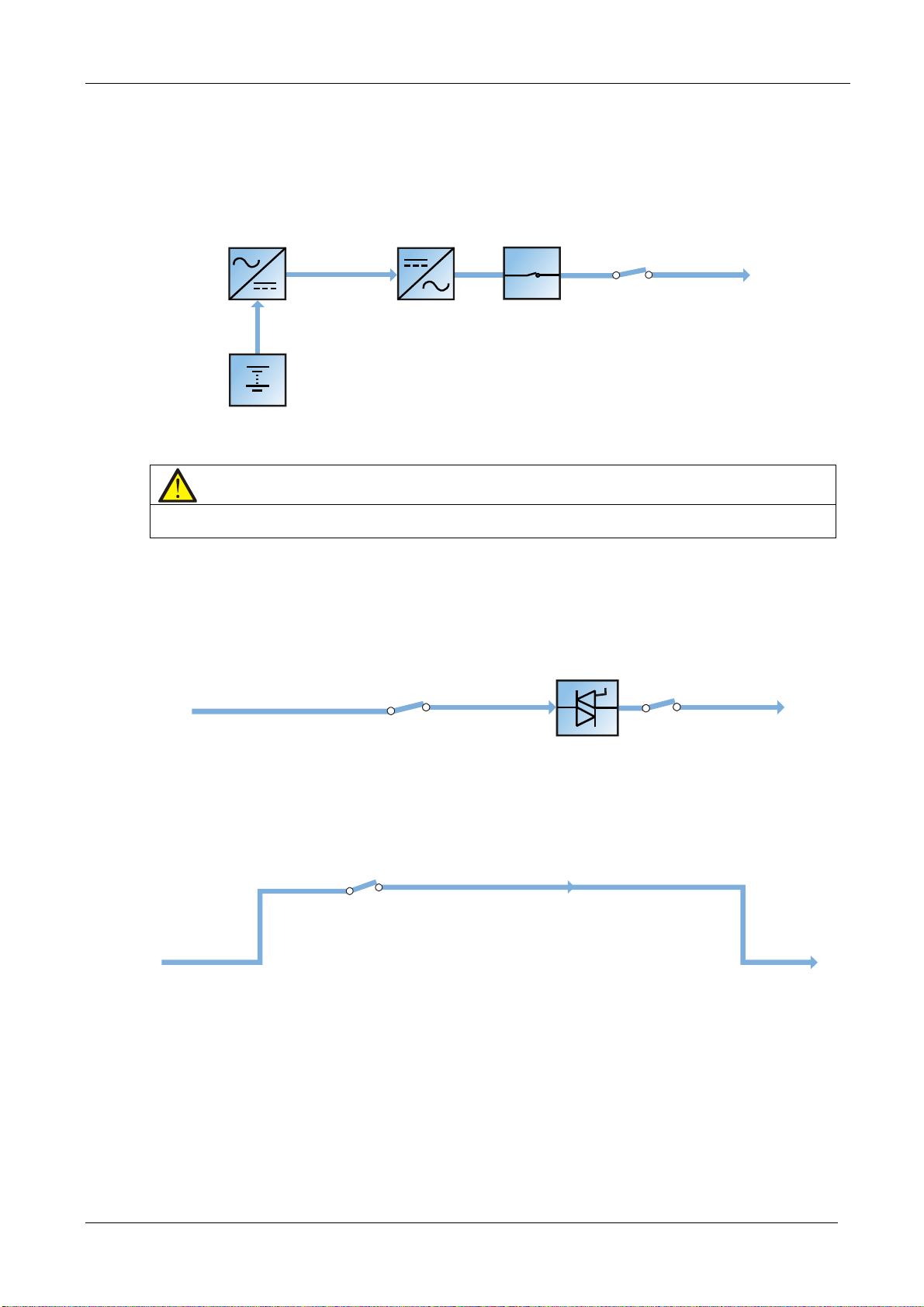
Battery mode
As shown in Figure 1-4, the operating mode where the battery provides the backup power supply to the loads
through the rectifier and inverter is called battery mode. In the event of a mains failure, the system will transfer
automatically to battery mode with no interruption in the power supply to the load. When the mains power supply is
restored, the system will re-transfer automatically to normal operating mode without any manual intervention, and
with no interruption in the power supply to the load.
EXS
Rectifier
Battery
Note
The battery cold start function may be used to switch the UPS on in Battery (charged) mode directly during mains failure.
This means that the battery power supply can be used independently to improve the availability of the UPS.
Inverter
Figure 1-4 Battery operating mode line diagram
Automatic inverter switch
UPS output
Output switch
Bypass mode
As shown in Figure 1-5, in normal mode, in the event of an inverter failure, inverter overload or inverter manual shut
down, the static switch will transfer the load from the inverter side to bypass side, with no interruption in the power
supply to the load. In this case, if the inverter and bypass are not synchronized, there will be a transitory interruption
in the power supply to the load (not exceeding 20ms).
Static switch
Bypass input
Bypass input switch
Output switch
UPS output
Figure 1-5 Bypass operating mode line diagram
Maintenance mode
As shown in Figure 1-6, if it is necessary to service the UPS or carry out maintenance work on it, you may use the
manual maintenance bypass switch to transfer the load to maintenance bypass, with no interruption in the power
supply to the load. This maintenance bypass switch is fitted in all UPS modules and rated for full load of one module.
Maintenance bypass switch
Bypass input
Figure 1-6 Maintenance operating mode line diagram
Maintenance bypass
UPS output
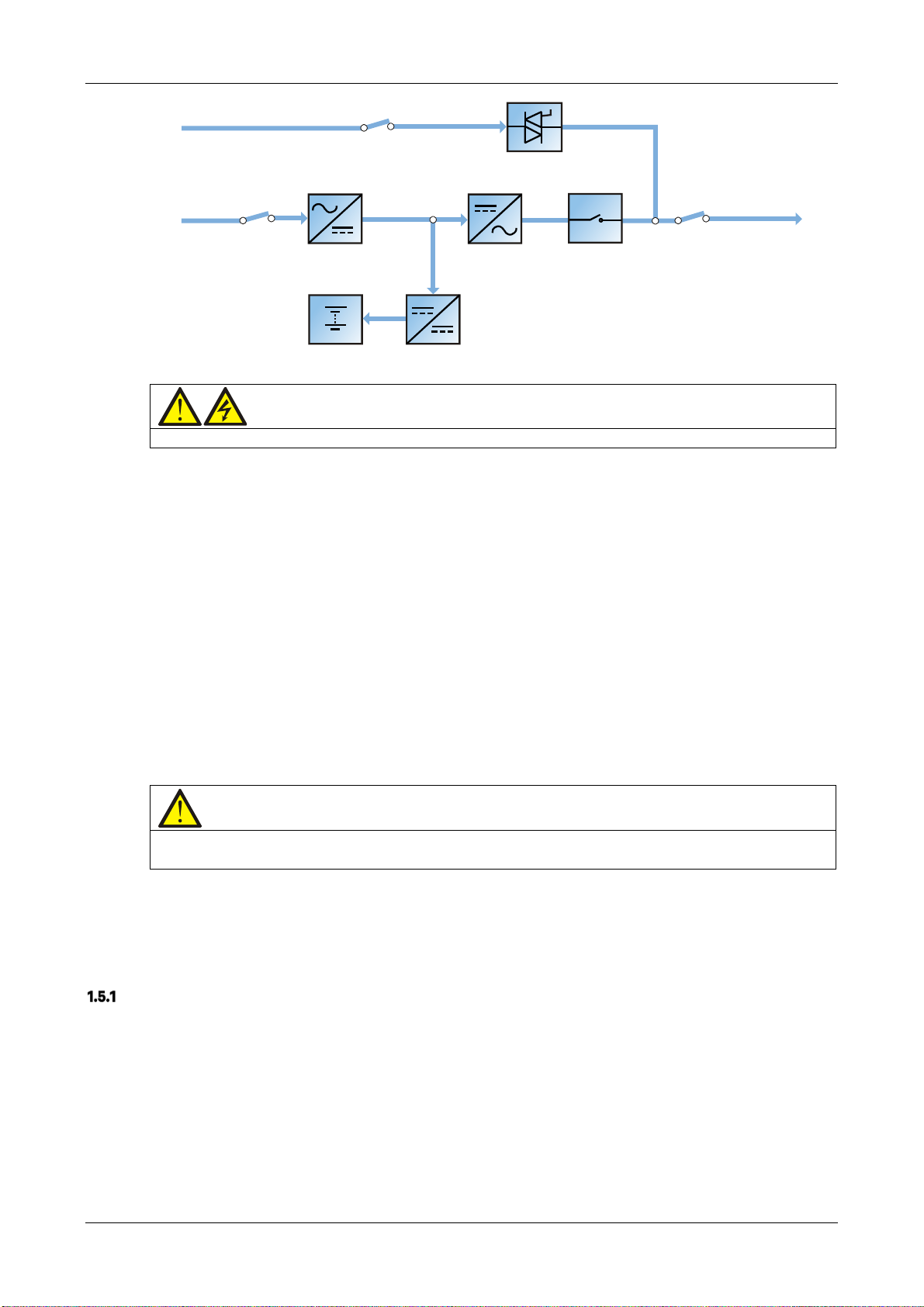
ECO mode
If ECO mode is selected, all the power switche
s and the circuit breaker are closed, and the system selects the
bypass as the preferred source of power for the load, in order to save energy. When the bypass supply frequency
and voltage are within normal limits (adjustable), the load is powered by the bypass, with the inverter on stand-by;
when the bypass voltage and/or frequency is outside these pre-defined and adjustable limits, the system will
transfer to the inverter output. In this mode, the system can charge the battery normally.
14 User Manual 10H52260UM60 - Rev. 1 - 10/2017
EXS
Bypass input
Mains input
Rectifier input switch
Static switch
Bypass input switch
InverterRectifier
UPS output
Output switch
Automatic inverter switch
Battery
Figure 1-7 ECO operating mode line diagram
Warning
The load is not protected against distortion on the mains voltage waveform in ECO mode.
Battery charger
Parallel redundancy mode (system expansion)
For higher capacity or higher reliability, or both, the outputs of multiple UPS modules can be programmed for
directly paralleling while a built-in parallel controller in each UPS module ensures automatic load sharing. The
parallel system may consist of up to four UPS modules. For the operating principle diagram of parallel redundancy
mode, see Figure 7-1.
LBS mode
A dual bus system consists of two independent UPS systems, each containing one or more parallel UPS modules.
The dual bus system provides high reliability, which makes it suitable for use with loads having multiple input
terminals. In the case of single-input loads, an STS may be installed to power the load. For the operating principle
diagram of LBS mode, see Figure 7-4.
Common battery string mode
In this mode, when the UPS modules (up to four UPS units) are connected in parallel, they share the same battery
string thus providing cost and space savings.
Note
Never use batteries having different brands, type or capacities in the same system. Common battery string mode is suitable
for parallel systems only, and is not compatible with LBS mode.
1.5 Battery Management
The following battery management functions are set by the service engineer using the VERTIV setting software.
Normal Function
1. Constant current boost charge
Uses a constant current (within battery charging limit) to charge the battery. This function can be used for fast
battery capacity recovery. It is possible to modify the value of the charge current.
2. Constant voltage boost charge
Uses a constant voltage to charge the battery. This function can be used for fast battery capacity recovery. In the
case of VRLA batteries, the maximum boost charge voltage should not exceed 2.4V/cell.
3. Float charge
User Manual 10H52260UM60 - Rev. 1 - 10/2017 15

This charging method is used for maintaining the battery at full capacity. The float charge voltage is generally low.
This function can be used to compensate for capacity loss due to battery self-discharging, and to recover battery
capacity.
In the case of VRLA batteries, the float charge voltage should be between 2.2V/cell and 2.3V/cell.
4. Automatic transfer to float charge
When the charge current is less than the 'Threshold of Equalize Charge to Float Charge’ value, the charger will
automatically transfer from boost charge to float charge. When the boost charge time exceeds the 'Equalize Charge
Protect Time Limit', the charger will be forcibly transferred to float charge in order to protect the battery.
5.Float charge temperature compensation (o
This fu
nction must be used together with the battery temperature detection device. The VERTIV battery
temperature sensor is a standard option designed to satisfy your requirements.
EOD
6.
protecti
When the batte
is disconnected in order to avoid further battery discharge. The EOD voltage may be set to between 1.6V/cell and
1.85V/cell (VRLA).
7.
Ba
ttery low pre-warning time
The battery low pre-warning time may be set to between 2min and 30min. The default setting is 2min.
mum battery discharge time
Maxi
8.
When the battery is discharged at low current levels for extended periods, it will result in excessive discharge and
may even cause irreparable damage, for this reason it is essential to set-up a maximum battery discharge time in
order to protect it. This limit value is set-up by the service engineer using the VERTIV setting software.
9. Maximum boost charge protection ti
T
o protect against the battery overcharge damage caused by long time boost charge, it is essential to set-up a
protection time a protect time limit This limit value is set-up by the service engineer using the VERTIV setting
software.
on
ry voltage falls to the EOD level, the the battery converter shuts down automatically and the battery
ptional)
me
EXS
Battery Temperature Compensation
The UPS system also features a battery charge temperature compensation function. When the ambient temperature
is increased, the DC bus voltage (which charges the battery) will be reduced correspondingly to provide optimal
charging voltage for the battery, thus prolonging the battery service life time. This function must be used together
with the VERTIV battery temperature detection device (standard option).
1.6 Battery Protection
The following battery protection functions are set by the service engineer using the VERTIV setting software.
Battery low pre-warning
The battery low pre-warning occurs before the EOD. The time can be set to between 2min and 30min.
EOD protection
When the battery voltage falls to the EOD level, the battery converter shuts down automatically. The EOD voltage
may be set to between 1.6V/cell and 1.85V/cell (VRLA).
16 User Manual 10H52260UM60 - Rev. 1 - 10/2017
EXS
Chapter 2 Mechanical Installation
This section provides a brief introduction to the UPS mechanical installation procedures, including the precautions,
initial inspection before installation, environmental requirement, mechanical requirement and installation diagram.
2.1 Precautions
This section describes the environmental and mechanical requirements and mechanical considerations that must be
taken into account when planning the positioning and cabling of the UPS equipment.
Because no two sites are the same, this section does not provide the detailed installation procedures, and is only
intended to act as a guide for the general procedures and practices that should be carried out by the installing
engineer, so that they can handle the specific situation at the site correctly.
Warning: professional installation required
1. Do not dismantle the packaging without the permission of an authorised service engineer.
2. The UPS should be installed by an authorised engineer in accordance with the information provided in this section.
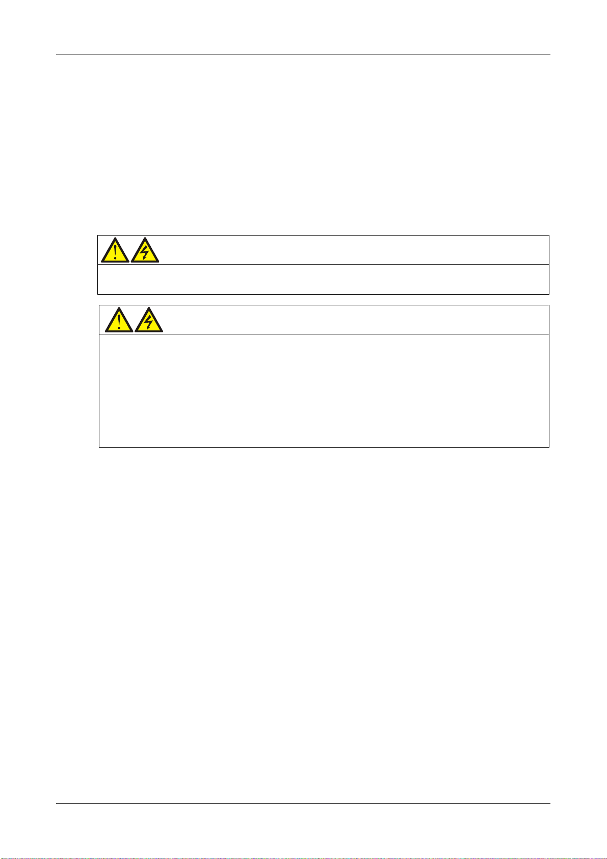
Warning: battery danger
Take special care when installing batteries. When connecting batteries, the battery terminal voltage will reach 320Vdc,
which is fatal to human beings.
1. Always wear safety glasses to protect the eyes from being damaged by arcing.
2. Remove all the metal items, including finger rings, watch, etc.
3. Use tools with insulated handles.
4. Wear rubber gloves.
5. If batteries are damaged or leak electrolyte they must be replaced. Place the battery into the container that can withstand
sulphuric acid and dispose of it according to the local regulations.
6. In the event of contact with electrolyte, wash the affected are with abundant clean water immediately.
2.2 Transportation
Rail and sea shipping are the recommended transportation methods. If road transportation is unavoidable, choose
roads that are less bumpy in order to protect the equipment.
The UPS cabinet is heavy (see Table 10-3 for the weight). We recommend using mechanical equipment such as an
electric forklift to unload and move the equipment to the place closest to the installation site.
User Manual 10H52260UM60 - Rev. 1 - 10/2017 17
EXS
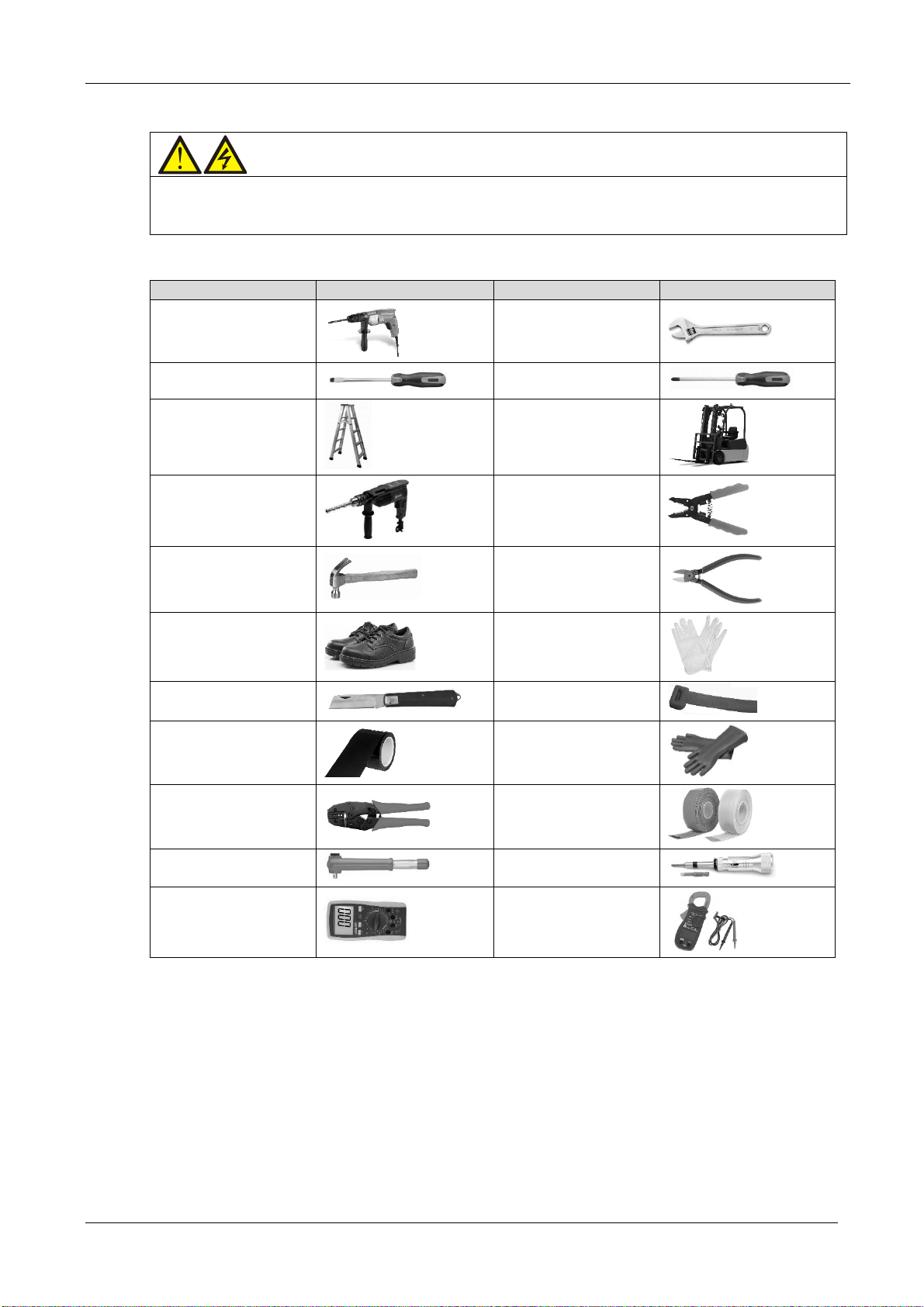
2.3 Tools
Warning
1. For reasons of safety, all installation tools used on live components must be insulated.
2. The tools listed in Table 2-1 are for reference only; please adapt to the actual requirements for on-site installation and
connection.
Name Drawing Name Drawing
Electric hand drill
Slotted screwdriver
Stepladder
Drill
Claw hammer
Table 2-1 Tools
Adjustable wrench
Cross head screwdriver
Forklift
Wire cutting pliers
Diagonal cutting pliers
Insulating shoes
Electrician’s knife
Insulating tape
Crimping pliers
Insulated torque wrench
Multimeter
Antistatic gloves
Cable ties
Insulating gloves
Heat shrinkable tube
Torque screwdriver
Clip-on ammeter
18 User Manual 10H52260UM60 - Rev. 1 - 10/2017
EXS
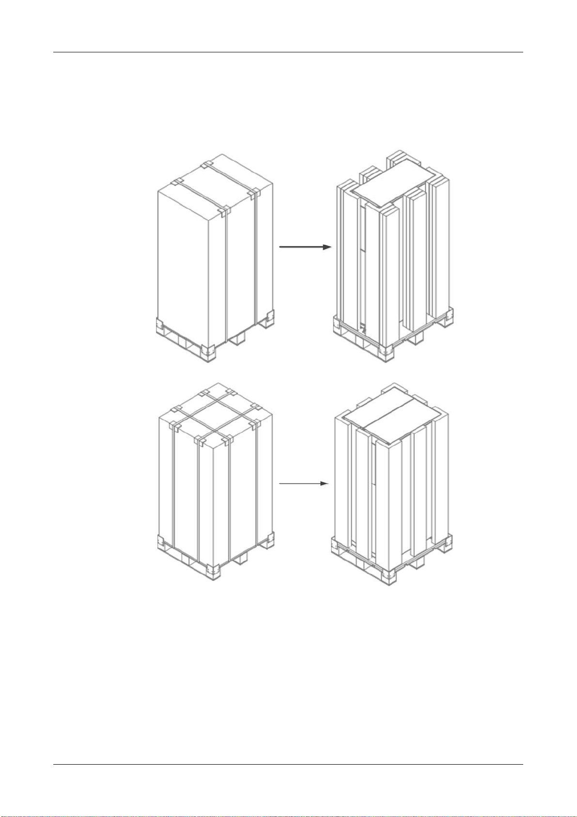
2.4 Unpacking
Unpack the UPS and battery packages under the supervision of an authorized service engineer.
Proceed as follows:
emove the cart
1. R
emove the packing strap and lift the whole carton upwards, as shown in Figure 2-1.
R
on.
Removing carton from standard UPS
Removing carton from UPS with side cabinet
Figure 2-1 Removing cartons
2. Remove the fixing structural parts from the bottom pallet (see Figure 2-2), do not throw them away. Next, use the
orklift (inserting the forks at the points illustrated in Figure 2-2) to move the cabinet close the installation site.
f
User Manual 10H52260UM60 - Rev. 1 - 10/2017 19
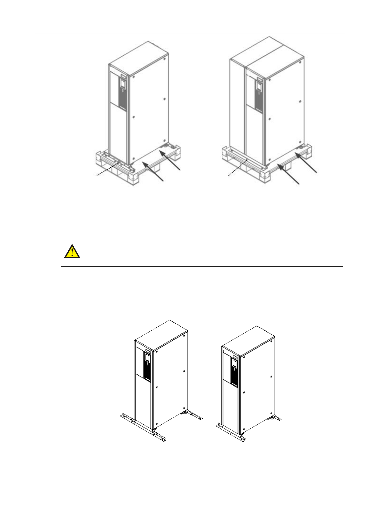
EXS
Remove the fixing
structural parts
Inserting
direction
Standard UPS UPS with side cabinet
Figure 2-2 Removing the bottom pallet
Remove the fixing
structural parts
Inserting
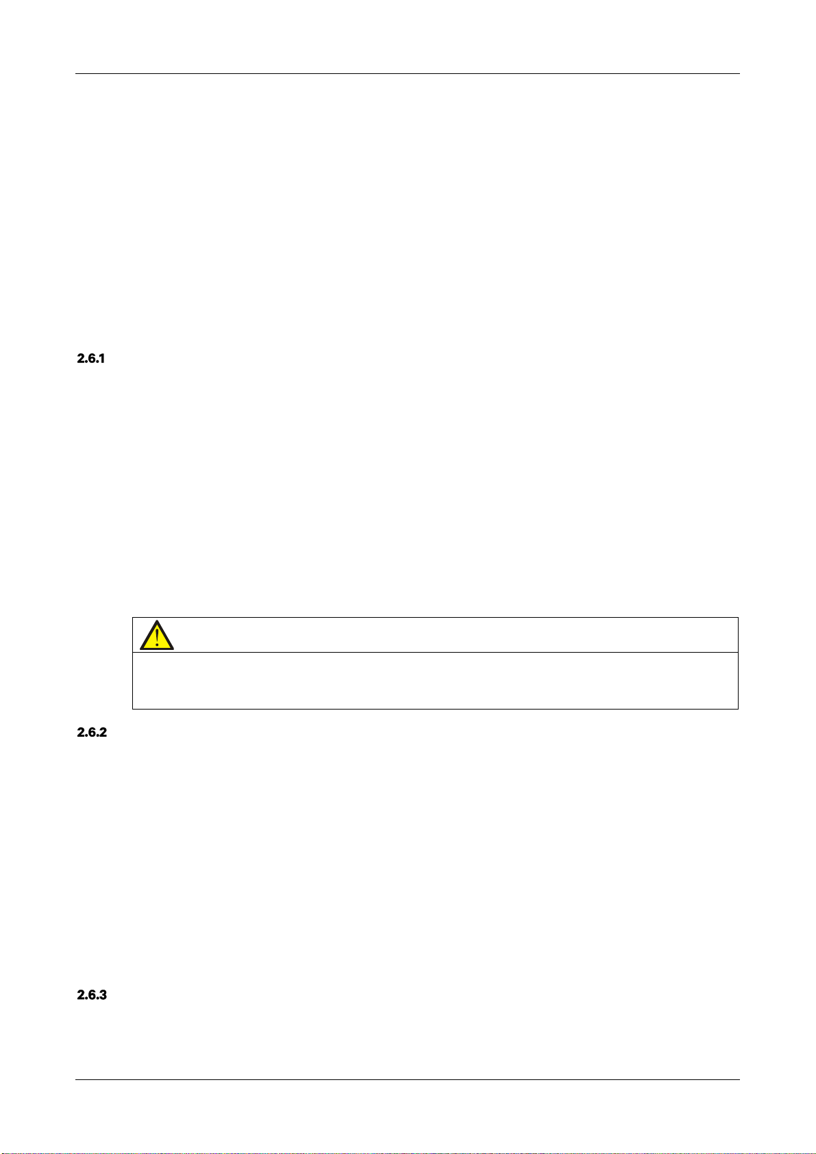
3. After moving the cabinet to the installation site, you raise the adjustable feet and use the castors to move the
cabinet to its final installation position, finally, rotate the adjustable feet until they are in contact with the floor. See
Figure 2-3 for the finished installation.
Note
1. It is not necessary to install the fastening structural parts of the bottom pallet in the case of UPS with side cabinet
2. In the case of standard UPS with internal batteries, simply secure the fastening structural parts removed
in step 2 to the cabinet bottom (See right drawing); in the case of standard UPS without internal batteries,
install the fastening structure parts to both the left and right hand sides (See left drawing) based on the
right drawing to avoid tipping.
UPS without internal batteries UPS with internal batteries
Figure 2-3 Completed installation
20 User Manual 10H52260UM60 - Rev. 1 - 10/2017
EXS
2.5 Initial Inspection
Before installing the UPS, carry out the following inspections:
1.Ensure that the UPS equipment room meets the environmental requirements specified in the product te
specifications, especially the ambient temper
Unpack the U
2.
and out
side of the UPS and battery for any shipping damage. If there is any damage, report it to the carrier
immediately.
3.Verify the UPS label and confirm that the UPS model conforms to the information indicated on it
ttached to the rear of the door. The UPS model, capacity and the main parameters are marked on the label.
a
PS and battery under the supervision of an authorized service engineer. Visually inspect the
2.6 Environmental Requirements
Selecting the UPS Location
The UPS should be located in a cool, dry, clean-air indoor environment with adequate ventilation, and should be
located on concrete or other non-flammable, flat surfaces. The surrounding environment should be free from
conductive powders (such as metallic powder, sulphide, sulphur dioxide, graphite, carbon fibre, conductive fibre,
etc.), acid mist or other conductive media (strongly ionized substances). The environmental specifications should
comply with relevant international standard & specifications and the operating range (see Table 10-2) specified in
this manual.
The UPS uses forced cooling by internal fans. Cooling air enters the UPS through the ventilation grills at the front of
the cabinet and is expelled through the ventilation grills at the back of the cabinet. Do not obstruct the ventilation
holes (ventilation grills). The rear of the UPS should be kept a distance at least 200mm from the wall to avoid
blocking the UPS heat dissipation, thus reducing the UPS internal temperature and improving the UPS life.
If necessary, install indoor extractor fans to aid cooling-air flow and avoid temperature build-up in the installation
area.
chnical
ature, ventilation conditions, and the levels of dust.
inside
. The UPS label is
Note
Note 1: When the battery cabinet is installed near the UPS, the maximum allowable ambient temperature is dependent on
the battery rather than the UPS.
Note 2: If the UPS is operating in ECO mode, the power consumption will be less than in Normal mode. A proper air
conditioning system shall be selected according to the normal operating mode.
Selection the Battery Location
Batteries generate a certain amount of hydrogen and oxygen at the end of the charging cycle, so the fresh air
volume of the battery installation environment must meet the EN50272-2001 requirements.
The ambient temperature is the main factor that affects the battery capacity and life. The normal operating
temperature of the battery is 20°C. If the ambient temperature is higher than 20°C, the battery life will be reduced. If
it is lower than 20°C, the battery capacity will be reduced. Under normal operating conditions, the acceptable
ambient temperature for the battery is 15°C to 25°C. The ambient temperature of the battery must be maintained
constant, and the battery must be kept away from heat sources and air outlets.
The battery may be installed inside the dedicated battery cabinet, which shall be positioned close to the UPS. If the
battery is placed on the raised floor, brackets shall be installed under the floor, just as for the UPS. In the case of
rack-mounted batteries or batteries that are installed remotely from the UPS, the battery circuit breaker shall be
installed close to the battery, and the cable lengths shall be kept to a minimum.
Storage
Should the UPS not be installed immediately, it must be stored in its original packaging in a location where it is
protected against excessive humidity and heat sources (see Table 10-2). The battery must be stored in a dry and
cool place with good ventilation. The most suitable storage temperature is between 20°C and 25°C.
User Manual 10H52260UM60 - Rev. 1 - 10/2017 21
EXS
Warning
Recharge the battery at regular intervals during storage in accordance with the manufacturer’s instructions. During the
charge process, connect the UPS temporarily to the mains and activate the battery by recharging it.
2.7 Mechanical Requirements
Moving the Cabinet
Warning
1. Ensure that the load capacity of the lifting equipment used to move the UPS cabinet is sufficient.
2. The UPS is fitted with castors. When removing the UPS from the shipping pallet, take care to prevent it from sliding.
Ensure that sufficient personnel and lifting equipment are available when removing the shipping pallet.
3. Due to the weight of the UPS cabinet, the castors may only be suitable for use on flat surfaces.
4. The centre of gravity of the UPS cabinet is high, take care to prevent it tipping over when moving it
5. The cabinet must never be suspended vertically.
Caution
Take special care when moving the battery cabinet with the batteries installed, making sure that each battery string has
been secured and keeping movements to a minimum.
Ensure that the UPS weight does not exceed the load capacity of the lifting equipment. For information about the
weight of the UPS, refer to Table 10-3.
The UPS may be moved using a forklift truck or similar lifting equipment.
The castors may be used when it is necessary to move it over short distances.
Clearance
Because the UPS is not fitted with lateral grilles, there is no special clearance requirement on either side.
In addition to any local regulations, in order provide sufficient space for routine operations, such as tightening the
power terminals inside the UPS, it is recommended that clearance around the front of the UPS should be sufficient
to enable free passage of personnel with the door fully open. In addition, it is necessary to leave a clearance of at
least 200 mm at the rear of the cabinet in order to permit adequate circulation of the hot air expelled by the UPS.
Cable Access Mode
UPS cable access is from the rear of the cabinet.
For details, refer to 3.1.10 and 3.2.8 .
22 User Manual 10H52260UM60 - Rev. 1 - 10/2017
EXS
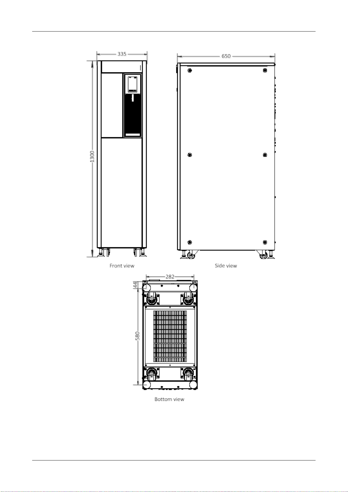
2.8 Installation Drawings
Figure 2-4 Front/side/bottom view of the standard UPS (unit: mm)
User Manual 10H52260UM60 - Rev. 1 - 10/2017 23
EXS
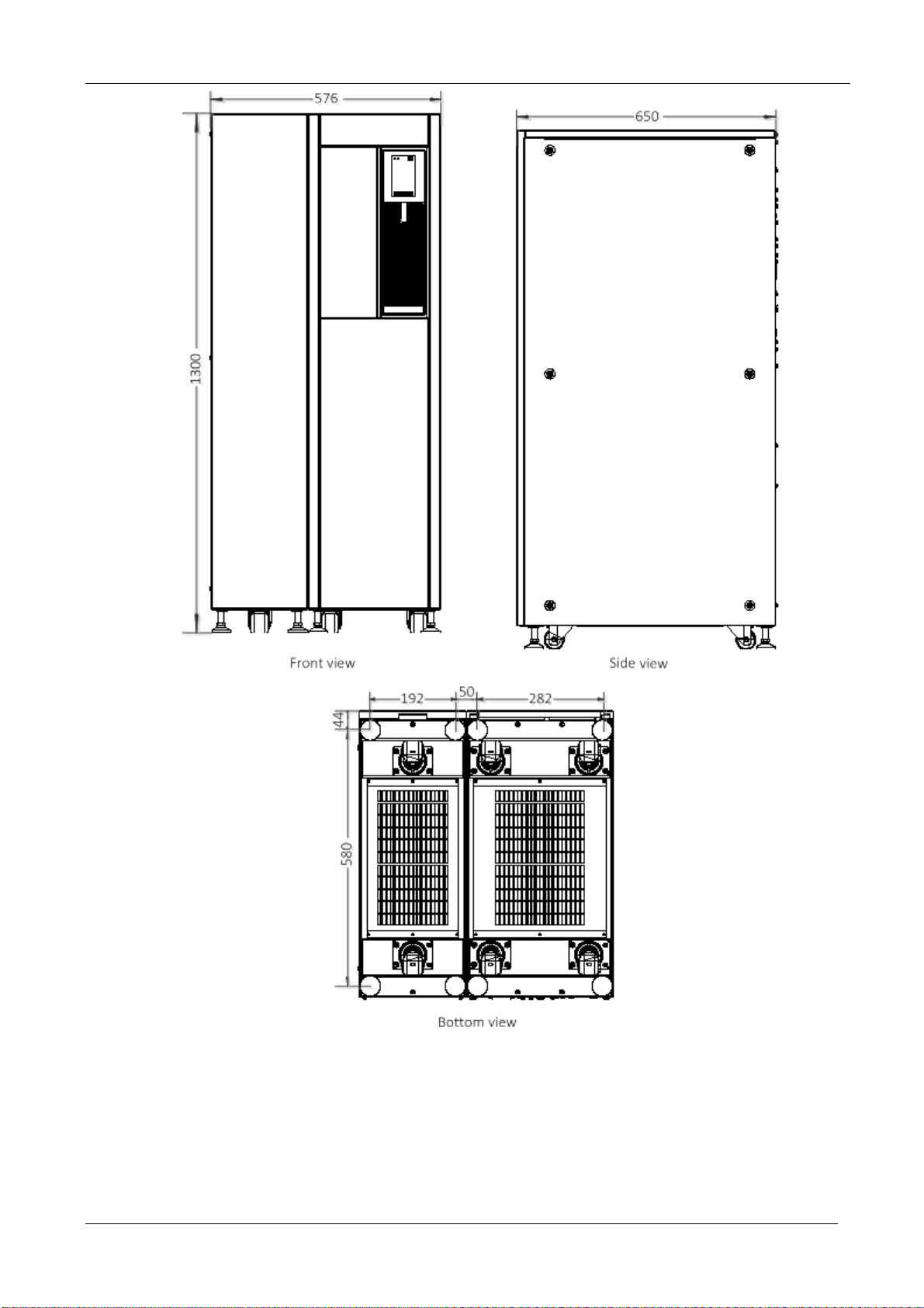
Figure 2-5 Front/side/bottom view of the UPS with side cabinet (unit: mm)
24 User Manual 10H52260UM60 - Rev. 1 - 10/2017
EXS
Chapter 3 Electrical Installation
This section principally introduces the UPS electrical installation procedures, including the power cable and signal
cable connecting procedures and methods.
Once the mechanical installation procedure is complete, it is necessary to connect the power and signal cables to
the UPS. All signal cables, whether or not they are shielded, must be kept away from the power cables.
Warning
1. Do not switch the UPS on before the authorised service engineer arrives.
2. The UPS should be routed by an authorised engineer in accordance with the information provided in this section.
3.1 Connecting the Power Cables
System Configuration
The system power cable dimensions shall meet the following requirements:
UPS input cable
The UPS input cable dimension differs depending on the UPS power ratings and input AC voltages, provided that it
meets the requirement of maximum input current, including the maximum battery charge current, see Table 3-1.
UPS bypass and output cable
The UPS bypass and output cable size differs depending on the UPS power rating and output AC voltages, provided
that it meets the requirement of nominal output or bypass current, as shown in Table 3-1.
Battery cable
Each UPS is connected to the respective battery positive pole, negative pole and neutral line by three cables . The
battery cable dimension differs depending on the UPS power ratings, provided that it meets the battery discharge
current requirement when the battery voltage nears the EOD level, as shown in Table 3-1.
Maximum Steady State AC and DC Currents
The power cable must be selected according to the current and voltage values indicated in Table 3-1, as well as the
local wiring regulations, as well as taking environmental conditions (temperature and physical media) into
consideration; refer to Table 3B in IEC 60950-1.
Table 3-1 Max. steady state AC and DC currents
Rated current (A)
UPS power
(kVA)
10 (3-in 3-out ) 22 16 15 14 35/35/15 M6 3
10 (3-in 1-out ) 22 48 45 42 35/35/15 M6 3
15 (3-in 3-out ) 33 23 22 21 52/52/25 M6 3
15 (3-in 1-out ) 33 69 66 63 52/52/25 M6 3
20 (3-in 3-out ) 44 31 29 28 70/70/30 M6 3
20 (3-in 1-out ) 44 93 87 84 70/70/30 M6 3
Max. input
current
Output/bypass current
1,2
at full load
380V 400V 415V
2
Battery discharge
current (+, -, N) at
min. battery voltage
Bus stud bolt/nut
specification
Input/batte
ry/output/
bypass
cable
Recommende
d torque
(N.m)
When selecting the battery cables, a max. volt drop of 4Vdc is permissible at the current ratings given in Table 3-1. Avoid coiling
the cables as this would increase the electromagnetic interference (EMI).
1. Input mains current for rectifier and bypass.
User Manual 10H52260UM60 - Rev. 1 - 10/2017 25
2. Non-linear load (like switch power) affects the design of output and bypass neutral line. The neutral line current may exceed
the rated phase current, at most 1.5 times of the rated phase current.
Recommended CSA of UPS Cables
The recommended CSA of the UPS cables is listed in Table 3-2.
Table 3-2 Recommended CSA of the UPS cable (unit: mm2, ambient temperature: 25°C)
Model Input Output Bypass Neutral line Earth cable Battery
10 (3-in 3-out ) 10 10 10 10 10 10
10 (3-in 1-out ) 10 10 10 10 10 10
15 (3-in 3-out ) 10 10 10 10 10 10
15 (3-in 1-out ) 10 16 16 16 16 10
20 (3-in 3-out ) 10 10 10 10 10 16
20 (3-in 1-out ) 10 25 25 25 25 16
When the system is in common input configuration and in 3-in 1-out mode, because phase A powers the load, the input cable of
phase A must be selected according to Table 3-2. Input cables of phase B and phase C may refer to Table 3-2.
Selecting the UPS I/O Switch
Table 3-3 indicates the recommended UPS I/O switch capacity, the user may select it as required.
EXS
Table 3-3 Selecting the UPS I/O switch
Model Input port External input switch
10
(3-in 3-out )
10
(3-in 1-out )
15
(3-in 3-out )
15
(3-in 1-out )
20
(3-in 3-out )
20
(3-in 1-out )
Terminal block 32A (3P) 50A Terminal block 25A (3P)
Terminal block 32A (3P) 50A Terminal block 63A (1P)
Terminal block 50A (3P) 63A Terminal block 32A (3P)
Terminal block 50A (3P) 63A Terminal block 80A (1P)
Terminal block 63A (3P) 80A Terminal block 50A (3P)
Terminal block 125A (3P) 80A Terminal block 125A (1P)
Distance Between the UPS Connection Point and the Floor
See Table 3-4 for details.
Table 3-4 Min. distance between UPS connection point and floor
UPS connection point
Circuit breaker
Min. distance(mm)
Output port
External
output switch
Rectifier input 1000
Bypass input 1000
AC Output 1100
Battery 1100
PE terminal 1100
Notes
The following points are provided for general guidance only. If there are corresponding local regulations, such
regulations shall prevail.
26 User Manual 10H52260UM60 - Rev. 1 - 10/2017

EXS
1. The protective earth cable dimension shall be selected according to the AC power failure level, cable length and
otection type. The grounding wire connection must use the shortest possible connection route.
pr
2. In the case of cables that are required to handle large current, it may be easier to use multiple smaller cables in
allel.
par
3. When selecting the battery cable dimension, it is important to take the current value in Table 3-1 into account and
mind that the maximum permissible voltage drop is 4 Vdc.
bear in
4.
Avoid coiling the cables as this would increase the electromagnetic interfer
Power Cable Connecting Terminal
The rectifier input, bypass input, output and battery power cables are connected to the corresponding terminals, as
shown in Figure 3-2.
Protective Earth
The protective earth cable must be connected securely to the PE input terminal (see Figure 3-2) using the fastening
bolt. All the cabinets and cable troughs shall be earthed according to the local regulations. The earthing wires shall
be secured in order to prevent them coming loose from the fastening screws if they are pulled.
Warning
Failure to earth the various elements as directed may result in EMI, electric shock or fire risk.
ence (EMI).
External Protective Device
To ensure safety, it is necessary to install external circuit breakers on the UPS input and battery lines. Because no
two installations are the same, this section is only intended to provide general practical guidelines for installation
engineers. Qualified installation engineers should be aware of the local wiring regulations and any other related
information
Rectifier and bypass input power supply
overcurrent and short circuit protection
1. Input
Install suitable protective devices on the mains input supply distribution line. The protective devices should provide
functions such as overcurrent protection, short circuit protection, isolation protection and tripping upon backfeed.
When selecting the protective devices, consider the power cable current-carrying capacity, system overload
capacity (see Table 10-6 and Table 10-7) and the short circuit capacity of the upstream power distribution.
2. Split bypass configurat
If the UPS
adopts the split bypass configuration, independent protective device shall be installed on both the
ion
rectifier input and bypass input distribution lines.
Note
1. The rectifier input and bypass input must use the same neutral line.
2. In the case of IT grid systems, a 4-pole protective device must be installed on the UPS external power distribution line.
3. Earth fault protection
If the ups
tream input power supply his fitted with an RCD, it is important to take the transient state and steady state
earth leakage current upon the start-up of the UPS into account.
The RCCB shall meet the following requirements:
Be sensitive to DC unidirectional pulses (class A) in the power distribution network
Be immune to transient current pulses
Have an average sensitivity of 0.3A - 3A (adjustable)
The R
CCB symbols are shown in Figure 3-1.
User Manual 10H52260UM60 - Rev. 1 - 10/2017 27
EXS
Figure 3-1 RCCB symbols
The UPS is fitted with an internal EMC filter, therefore the protective earth cable leakage current is 0 - 1000mA. We
recommend confirming the RCD sensitivity of the upstream input power distribution and downstream power
distribution (to the load) lines.
External battery
The circuit breaker must be installed in order to protect external battery.
This circuit breaker is extremely important for the battery maintenance, and is generally installed close to the battery.
System output
The UPS output distribution line must be fitted with a protective device. The protective device must be different
from the input distribution protection switch and be able to provide overload protection (refer to Table 10-6 and
Table 10-7 ) .
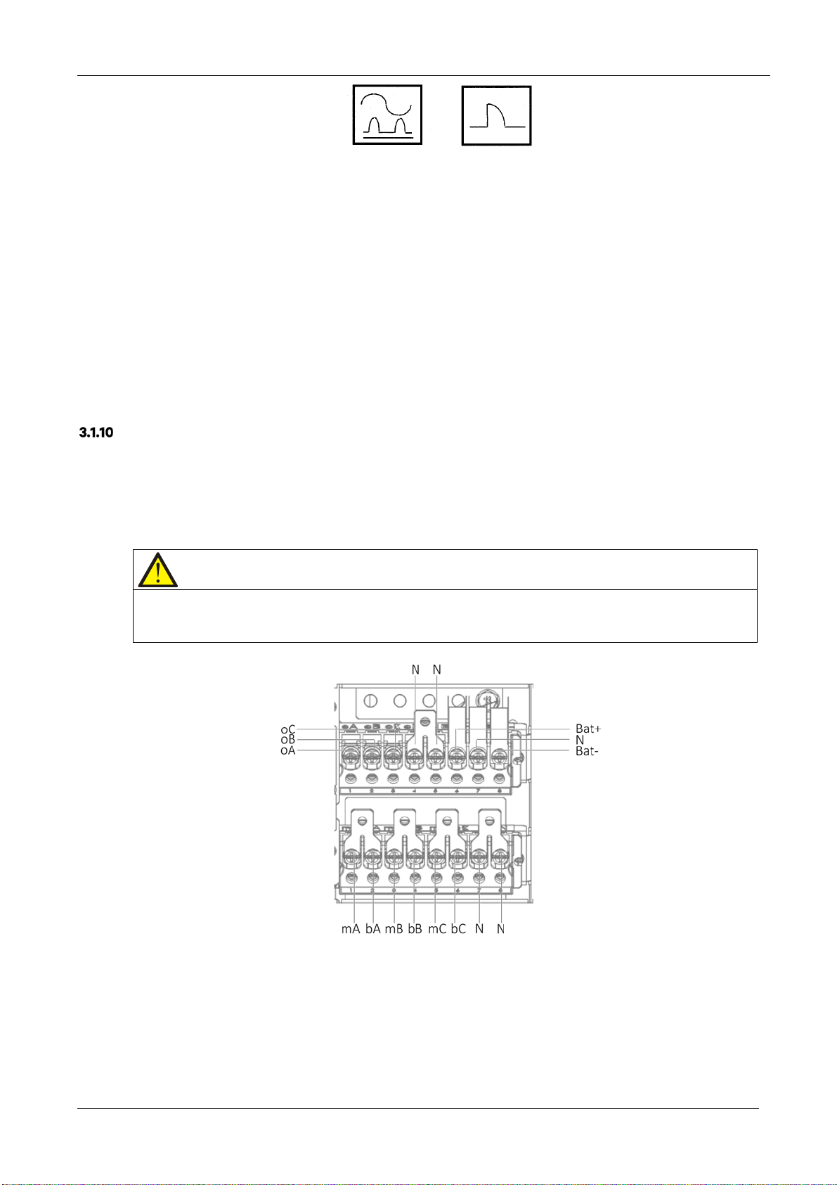
Power Cable Connection Steps
For the UPS cable access mode, refer to 2.7.3 .
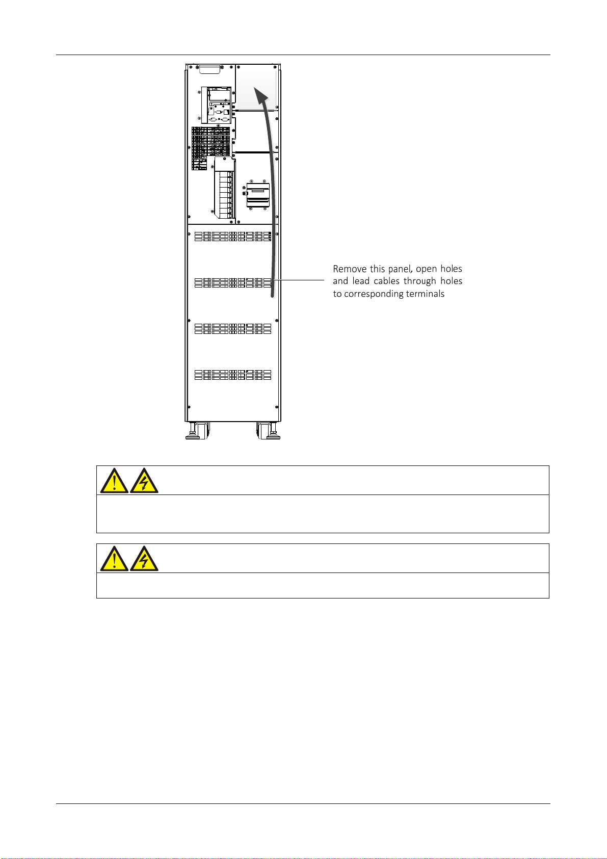
Connection terminals and cable routing method
Figure 3-2 shows the UPS power cable connection terminals. Figure 3-3 shows the power cable entry and routing
methods.
Note
1. Open the appropriate holes on the rear protective cover before routing the power cables. Install cable guards around the
rims of the hole to protect power cables against cutting.
2. Feed the power cables through the holes, then connect them to the corresponding terminals.
Figure 3-2 Power cable connection terminals (rear view)
28 User Manual 10H52260UM60 - Rev. 1 - 10/2017
EXS
Figure 3-3 Power cables wiring diagram (rear cable access)
Warning
1. Before connecting the cables, make sure that all the external and internal UPS power switches are set to OFF, and post the
appropriate warning signs to prevent inadvertent operation of the switches.
2. Measure the voltages between the UPS terminals, and the voltages between the terminals and earth.
rning
Wa
1. The earth cables and neutral line must be connected in accordance with local and national codes of practice.
2. Failure to observe this condition may result in electric shock or fire risk.
Power distribution mode
Based on the user's requirements, it is possible to select one of the following I/O cable connection configurations:
3-in 3-out, common input configuration (factory default)
3-in 3-out, split bypass configuration
3-in 1-out, common input configuration
3-in 1-out, split bypass configuration
Connecting th
1. 3
-in 3-out, common input configuration (factory default)
e system input
Refer to Figure 3-4, connect the AC input cables to the three copper shorting bars between the rectifier input
terminals (mA-mB-mC) and the bypass input terminals (bA-bB-bC) in the cabinet. Connect the input neutral line to
the terminal N in the cabinet. Make sure that the phase rotation is correct.
User Manual 10H52260UM60 - Rev. 1 - 10/2017 29
 Loading...