

Vertiv LIEBERT EXS Quick Installation Manual
LIEBERT® EXS™ UPS
208/220 ‑V 15 – 20 KVA
Quick Installation Guide
Removing Packaging and Moving the UPS
Ramp in
shipping position
I M P O RTANT: Before installing,
connecting to supply or operating
your Liebert EXS UPS, please
review the Safety and Regulatory
Statements sheet. For detailed
installation, operating, maintenance
and troubleshooting information
visit the EXS product page for the
EXS User Guide available at
www.VertivCo.com.
INSTALLATIO N
Inspecting the UPS
Inspect the UPS for any signs of
obvious damage. If damage is
visible, do not proceed. File a
damage claim with the carrier
immediately and send a copy to:
Vertiv Corporation
1050 Dearborn Drive
P.O. Box 29186
Columbus OH 43085
Attn. Traic Department
Packaging
Choosing a location
Install the UPS in a clean, wellventilated environment with the
ambient temperature range of 32°F
to 104°F (0°C to 40°C).
For installation and maintenance,
3ft (914mm) clearance is required
in the front and rear of the unit. For
proper ventilation during normal
operation, leave 8in. (203mm)
clearance on the rear. No side
clearance is required for installation
or operation of the UPS.
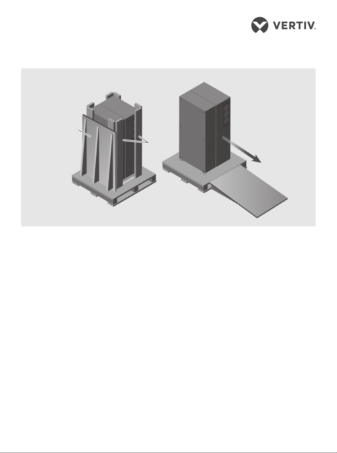
Handling and unpacking
the unit
The UPS ships on a pallet and is
equipped with casters that permit
two or more people to roll it o the
pallet for installation. Use a forklift
or pallet jack to move the palleted
UPS as close as possible to the
installation location before
removing packing material or
loosening shipping brackets.
Repositioned ramp placed
for unit transfer to
installation location
1. Remove the protective
packaging, shown in the
illustration at the top-right.
2. Locate the accessories
package on top of the UPS and
set aside.
3. Use a 16-mm (5/8 -in.) wrench
or socket to un-bolt the
shipping brackets from the
pallet.
4. Un-bolt the shipping brackets
from the front and rear of the
UPS. Remove the front lower
panel from the UPS to remove
the front bracket.
5. Make sure the leveling feet are
raised so they do not interfere
when rolling the unit on the
casters.
6. Roll the unit down the ramp to
the installation location, see
the illustration above, and
lower the leveling feet to fix the
UPS in the install location.
590-1912-501B/SL-26156_REV 1 1
LIEBERT® EXS™ UPS 208/220 ‑V 15 – 20 KVA
Quick Installation Guide
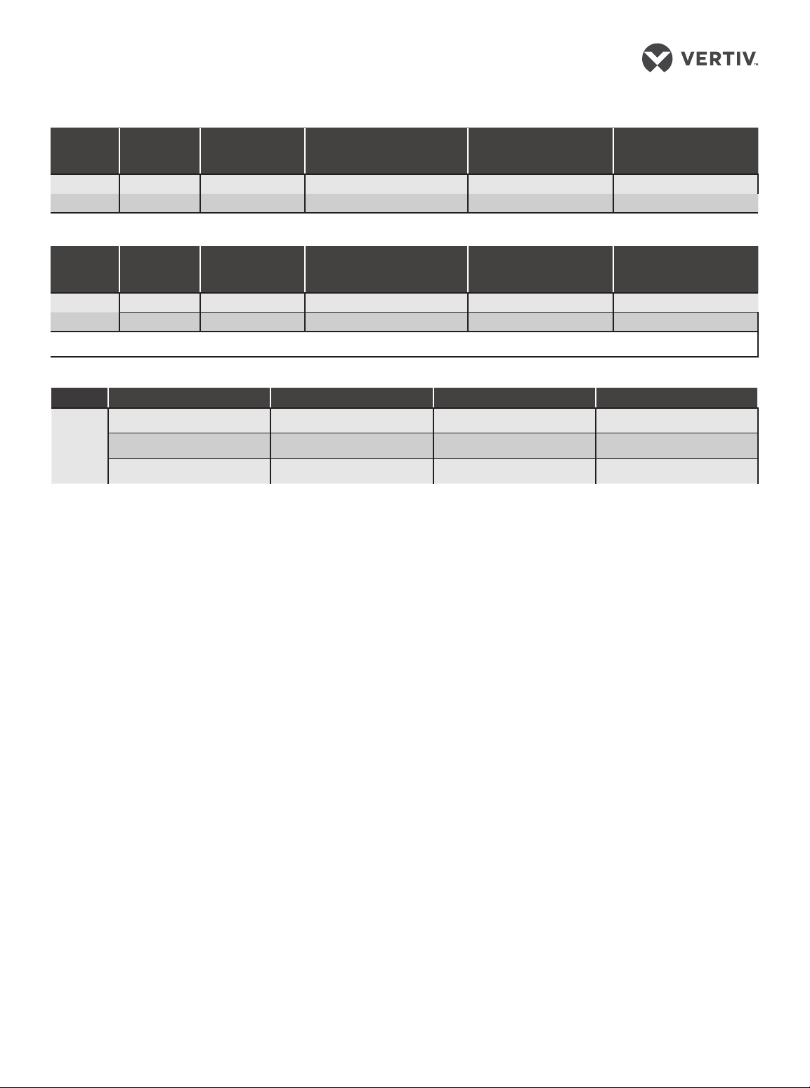
Table 1 Currents and Wire Size — UPS rectifier input
Unit Rating
15 kVA /k W 53 70 3 AWG 4 AWG 6 AWG
20 kVA /k W 71 90 2 AWG 6 AWG 6 AWG
Table 2 AC Currents and Wire Size — UPS bypass input* and output
Unit Rating
15 kVA /k W
20 kVA /k W
*Bypass input for dual-input configurations only.
Table 3 Recommended lug sizes
Part
Number
Maximum Input
Current (A)
Maximum Input
Current (A)
42 60 4AWG 4 AWG 6 AWG
56 70 3 AWG 3 AWG 6 AWG
6AWG (13.3mm2) 4AWG (21.2mm2) 3AWG (26.7mm2) 2AWG (33.6mm2)
McMaster-Carr: 7113K366 McMaster-Carr: 7113K441 McMaster-Carr: 6926K54 McMaster-Carr: 6926K54
Thomas & Betts: RE6-14 Thomas & Betts: 54138NT02 Thomas & Betts: 54107NT Thomas & Betts: 54107NT
Recommended OPD,
AmpTrip
Recommended OPD,
AmpTrip
—
75°C THW Copper Wire (phase)
Number of C ables per phase:1
75°C THW Copper Wire (phase)
Number of C ables per phase:1
Thomas & Betts: 54106NT — Tyco Electronics: 132331-1
75°C THW Copper Wire
neutral)
Number of C ables:1
75°C THW Copper Wire
(neutral)
Number of C ables:1
75°C THW Copper Wire
(ground)
Number of C ables: 1
75°C THW Copper Wire
(ground)
Number of C ables: 1
POWER WIRING AND
CONDUIT
When connecting wiring, follow the
local wiring regulations, and take the
environment situation into account.
NOTE : The conduit size and wiring
method must be in accordance with
all local, regional and national codes
and regulations, including NEC
ANSI/NFPA 70.
The maximum current for operating
modes, the recommended wire
sizes, and the recommended power
cables and plugs are listed in Tables
1 to 3, above, and are based upon
an
86°F (30°C) ambient temperature.
Lock-out and tag before
you begin
Ensure that the feeder breakers are
open and locked, and tagged to
prevent inadvertent operation by
unauthorized personnel.
2 590-1912-501B/SL-26156_RE V1
LIEBERT® EXS™ UPS 208/220 ‑V 15 – 20 KVA
Quick Installation Guide
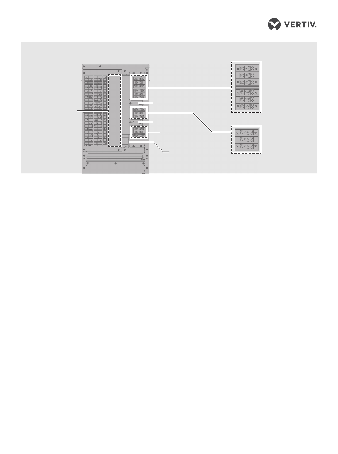
Terminal Block Connections—Compression Type
Conduit-entry
panel
HARDWIRE INPUT/OUTPUT
CONNECTIONS
Connecting a single-input
configuration with
compression-type terminal
blocks
1. On the rear panel of the UPS,
remove the cover plate to
access the terminal blocks,
shown in the “Compressiontype” illustration above.
2. Remove the conduit-entry
panel, punch holes for the
conduit, connect the conduit to
the panel, and re-install the
conduit-entry panel.
3. Referring to the “compressiontype” illustration, make the
following input connections
from the upstream feeder
panel to the input terminal:
• Phase A to rA
• Phase B to rB
• Phase C to rC
• Neutral to N
• Ground cable to ground bus
4. Make the following output
connections from the UPS
output terminal to the
downstream distribution-panel
main lug breaker:
5. Torque phase conductor
6. Reinstall the terminal-block
Connecting a dual-input
configuration with
compression-type terminal
blocks
1. On the rear panel of the UPS,
2. Remove the conduit-entry
3. Referring to the “Compression-
Single or
rectifier input
Input neutral
Output neutral
BATTERY TERMINALS
Ground busbar
dual input
Main lug
breaker
• Terminal A to Phase A
• Terminal B to Phase B
• Terminal C to Phase C
• Terminal N to neutral bus
• Ground (PE) to ground bus
connections to 110 lb-in, and
neutral and ground conductor
connections to 126 lb-in.
cover plate.
remove the cover plate to
access the terminal blocks,
shown in the “Compressiontype” illustration above.
panel, punch holes for the
conduit, connect the conduit to
the panel, and re-install the
conduit-entry panel.
type” illustration, relocate and
re-torqe the wires from the
factory-connections side of the
input terminal block to the
factory-side bypass terminal
INPUT
TERMINALS
Factory connections
Bypass
OUTPUT
TERMINALS
Factory
connections
block, and re-torque to 50lb-in.
as follows:
• wire BP-R to bA
• wire BP-S to bB
• wire BP-T to bC
4. Make the following rectifierinput connections from the
upstream feeder panel to the
input terminal:
• Phase A to rA
• Phase B to rB
• Phase C to rC
• Neutral to N
• Ground cable to ground bus
5. Make the following bypassinput connections from the
upstream feeder panel to the
input terminal:
• Phase A to bA
• Phase B to bB
• Phase C to bC
• Neutral to N
• Ground cable to ground bus
6. Make the following output
connections from the UPS
output terminal to the
downstream distribution-panel
main lug breaker:
• Terminal A to Phase A
• Terminal B to Phase B
590-1912-501B/SL-26156_REV 1 3
 Loading...