

Vertiv Liebert EXM series, EXM 0160kTK16FN01000, EXM 0080kTK16FN01000, EXM 0200kTK16FN01000, EXM 0120kTK16FN01000 User Manual
...
Liebert EXM 80kVA ~ 200kVA UPS
User Manual
Version: V1.2
Revision date:
November 30, 2017
BOM: 3101
Vertiv provides customers with technical support. Users may contact the nearest Vertiv local sales
office or service center.
2015
All rights reserved. The contents in this document are subject to change without notice.
Vertiv Tech Co., Ltd.
Address: Block B2, Nanshan I Park, No.1001 Xueyuan Road, Nanshan District, Shenzhen, 518055,
P.R.China
Homepage: www.Ver
E
3268
Copyright 2017 by Vertiv Tech Co., Ltd.
tivCo.com
-mail: overseas.support@vertivco.com


Special Declaration
Personnel Safety
1. This product must be installed and commissioned by professional engineers of the manufacturer or
its authorized agent. Failure to observe this could result in product malfunction or personnel safety
risk.
2. Take the time to read this product manual and the safety precaution thoroughly before installing
and commissioning this product. Failure to observe this could result in product malfunction or
personnel safety risk.
3. This product is not intended for life support equipment application.
4. Never dispose of the internal or external battery of this product in a fire, as it may explode and
jeopardize personnel safety when exposed to flame.
Product Safety
1. If this product will be stored or remain de-energized for a long period, it must be placed in a dry and
clean environment within specified temperature range.
2. This product should be used in an appropriate operating environment. For details, refer to the
section on the environmental requirement in this manual.
3. This product is not designed for application in an environment:
Where the temperature and relative humidity are outside the specifications
Subject to vibrations or shocks
Where conductive dusts, corrosive gases, salts, or flammable gases are present
Near heat sources or strong electromagnetic interferences
Disclaimer
Vertiv disclaims any and all responsibility or liability for the defects or malfunction caused by:
Application range or operating environment outside the specifications
Unauthorized modification, improper installation or operation
Force majeure
Other actions not in compliance with the instructions in this manual
Important
The UPS with standard configuration is a category C3 product for commercial and industrial application in the
Important
The UPS adding C2 EMC option based on the standard configuration is a category C2 product for a residential
Conformity and standards
This product complies with CE 2006/95/EC (low voltage safety) and 2004/108/EC (EMC), EMC standards of
Continued compliance requires installation in accordance with these instructions and the use of manufacturer
Warning
The selection of the upstream distribution protection equipment of the UPS shall be selected in accordance
Warning: high earth leakage current
Earth connection is critical before connecting the input supply (including both mains supply and battery).
Safety Precaution
Always observe the following safety symbols!
Used to alert the user to the risk of death or severe injury should the unit be used improperly.
Used to alert the user to the risk of injury or equipment damage should the unit be used improperly.
Used to advise the user to carefully read and observe this unit though it may not cause damage.
This manual contains information concerning the installation and operation of the Liebert EXM
80kVA ~ 200kVA UPS.
Read this manual thoroughly before installing, using and servicing the UPS.
second environment. Installation restrictions or additional measures may be needed to prevent disturbances.
environment or commercial and industrial application in the second environment.
Australia and New Zealand (C-Tick), and the following UPS product standards:
* IEC62040-1 General safety requirements for UPS
* IEC62040-2-EMC
* IEC62040-3 Performance requirements and test methods
For details, refer to Chapter 11 Specifications.
approved accessories only.
with the details in 3.1.4 Selection Of UPS I/O Switch and shall comply with the local electrical regulations.
This equipment is installed with an EMC filter.
Earth leakage current is less than 3000mA.
Transient and steady state earth leakage currents, which may occur when the equipment is started, should be
Warning: backfeeding protection
This UPS is fitted with a dry contact closure signal for use with an external automatic disconnect device
st backfeeding voltage into the incoming terminal through the rectifier or
Risk of voltage backfeed! Isolate the UPS, then check for hazardous voltage between all terminals including the
User serviceable components (For service personnel)
All equipment maintenance and servicing procedures involving internal access requires the use of a tool and
serviceable parts behind covers requiring a
Battery voltage exceeds 400Vdc (For service personnel)
All physical battery maintenance and servicing procedures requires the use of a tool/key and should be carried
General safety (For users)
Like other types of large power equipment, the UPS and battery circuit breaker box/battery cabinet have high
Multiple power inputs (For users)
This UPS system receives power from more than one source. Disconnection of all AC source and the DC
taken into account in the selection of instantaneous RCCBs or RCD devices.
RCCB which is sensitive to unidirectional DC pulse (class A) and insensitive to transient state current pulse
must be selected.
Note also that the earth leakage currents of the load will be carried by the RCCBs or RCDs.
The equipment must be earthed in accordance with the local electrical code of practice.
(supplied by others) to protect again
bypass static switch circuit. A label must be added at all external incoming primary supply disconnect device to
warn service personnel that the circuit is connected to a UPS. The text of the label has the following meaning:
protective earth before working on this circuit.
should be carried out only by trained personnel. There are no usertool/key for removal.
out only by trained personnel.
Take special care when working with the batteries associated with this UPS. When connected together, the
battery terminal voltage will exceed 400Vdc and is potentially lethal.
Battery manufacturers supply details of the necessary precautions to be observed in working on, or in the
vicinity of, a large bank of battery cells. These precautions should be followed implicitly at all times. Particular
attention should be paid to the recommendations concerning local environmental conditions and the provision
of protective clothing, first aid and fire-fighting facilities.
voltage inside. Because the components with high voltage can be accessed only when the front door is
opened, the risk of contacting high voltage has been minimized. This equipment meets the IP20 standard, and
other safety shields are provided inside the equipment.
There will not be any risk when operating this equipment according to the general instructions and the steps
recommended in this manual.
source is required before servicing.
This UPS has several circuits that are energized with high AC as well as DC voltages. Check for voltage with
both AC and DC voltmeters before working within the UPS.
Warning
When the internal fuse of the UPS is damaged, it must be replaced with fuse of the same electric parameters
Important
Beside the communication board is a static sensitive area, an ESD-proof action is critical before contacting
Warning
The user must select an appropriate MCCB to protect against short circuit and overload for the battery. It is
by qualified personnel.
with this area.
recommended to adopt Vertiv BCB to provide a better solution.

Product
Model
80kVA
EXM 0080kTK16FN01000
100kVA
EXM 0100kTK16FN01000
120kVA
EXM 0120kTK16FN01000
160kVA
EXM 0160kTK16FN01000
200kVA
EXM 0200kTK16FN01000
The Manual Describes The Following Equipment

Revision Information
V1.0 (June 4, 2015)
Initial release.
V1.1 (November 25, 2016)
Update Sections 2.4, 3.1.2 ~ 3.1.5, 3.2.7, 8.2.1, 9.1; Tables 4-7, 8-1, 11-6; Figures 3-2, 3-6, 3-12, 5-1, 6-6;
change 'dry contact card' to 'IS-RELAY'.
V1.2 (November 30, 2017)
Update Table 3-5, Figure 6-6, Figure 8-1; change all the contents in Chapter 4; change most part of
contents in Chapter 5; rearrange the sequence from Section 6.9; add Section 8.2.7; update Appendix 2;
update information about Vertiv.

Contents
Chapter 1 Overview ........................................................................................................................................1
1.2 Design Concept ............................................................................................................................................. 1
1.2.1 System Design ................................................................................................................................................... 1
1.2.2 Bypass ................................................................................................................................................................ 2
1.2.3 System Control Principle ................................................................................................................................. 2
1.2.4 UPS Power Supply Switch Configuration ...................................................................................................... 3
1.2.5 Battery Circuit Breaker (BCB) ......................................................................................................................... 4
1.3 Parallel System .............................................................................................................................................. 4
1.3.1 Parallel System Features .................................................................................................................................. 4
1.3.2 Parallel System Requirements ........................................................................................................................ 5
1.4 Operation Modes ........................................................................................................................................... 5
1.5 Battery Management ..................................................................................................................................... 8
1.5.1 Normal Function ................................................................................................................................................ 8
1.5.2 Advanced Function .......................................................................................................................................... 9
1.5.3 Battery Temperature Compensation............................................................................................................10
1.6 Battery Protection ........................................................................................................................................10
Chapter 2 Mechanical Installation ................................................................................................................. 11
2.1 Precautions ..................................................................................................................................................11
2.2 Transportation .............................................................................................................................................11
2.3 Tools ............................................................................................................................................................12
2.4 Unpacking....................................................................................................................................................13
2.5 Initial Inspection...........................................................................................................................................15
2.6 Environmental Requirement .........................................................................................................................15
2.6.1 UPS Location Selection ..................................................................................................................................15
2.6.2 Battery Location Selection ...........................................................................................................................15
2.6.3 Storage ............................................................................................................................................................16
2.7 Mechanical Requirement ..............................................................................................................................16
2.7.1 Composition ....................................................................................................................................................16
2.7.2 Moving Cabinet ..............................................................................................................................................16
2.7.3 Clearance ........................................................................................................................................................16
2.7.4 Cable Access Mode .......................................................................................................................................17
2.8 Installation Drawings ...................................................................................................................................18
Chapter 3 Electrical Installation .................................................................................................................... 19
3.1 Wiring Of Power Cable ..................................................................................................................................19
3.1.1 System Configuration .....................................................................................................................................19

3.1.2 Maximum Steady State AC And DC Currents .............................................................................................19
3.1.3 Recommended CSA Of UPS Cable ................................................................................................................20
3.1.4 Selection Of UPS I/O And Battery Switch ...................................................................................................20
3.1.5 Distance Between The UPS Connection Point And The Floor ..................................................................20
3.1.6 Notes ................................................................................................................................................................20
3.1.7 Power Cable Connecting Terminal ...............................................................................................................21
3.1.8 Protection Ground ..........................................................................................................................................21
3.1.9 External Protective Device ............................................................................................................................21
3.1.10 Power Cable Connection Steps ...................................................................................................................22
3.2 Wiring Of Signal Cable .................................................................................................................................28
3.2.1 Overview ..........................................................................................................................................................28
3.2.2 Dry Contact Port J21 .....................................................................................................................................29
3.2.3 Dry Contact Port J22 .....................................................................................................................................29
3.2.4 Dry Contact Port J26 ....................................................................................................................................30
3.2.5 Programmable Dry Contact Ports J23 ~ J25 ..............................................................................................31
3.2.6 REPO Port .......................................................................................................................................................33
3.2.7 RS232 Communication Port ..........................................................................................................................34
3.2.8 Parallel And LBS Communication Ports ......................................................................................................34
3.2.9 Intellislot Port .................................................................................................................................................35
3.2.10 Signal Cable Connection Steps...................................................................................................................35
Chapter 4 Operator Control And Display Panel .............................................................................................. 40
4.1 Introduction..................................................................................................................................................40
4.2 Navigating Through The Liebert EXM Touchscreen Control Panel ..............................................................41
4.2.1 Access Level Log-In .......................................................................................................................................41
4.2.2 Liebert EXM Touchscreen Control Panel Components .............................................................................42
4.3 Operation .....................................................................................................................................................46
4.3.1 Log In To The Liebert EXM Touchscreen Control Panel ...........................................................................46
4.3.2 Customizing The Display ..............................................................................................................................47
4.3.3 Operator Controls ..........................................................................................................................................52
4.4 Viewing UPS Status .....................................................................................................................................55
4.4.1 Viewing UPS Data With The Status Gauge .................................................................................................56
4.4.2 Viewing UPS Data With The Status Panel ..................................................................................................57
4.4.3 Logs—Alarms And Events ............................................................................................................................61
4.5 Viewing UPS Component Status ..................................................................................................................62
4.6 Status Bar Component .................................................................................................................................64
4.6.1 Status Bar Messages .....................................................................................................................................64
4.7 Alarm List ....................................................................................................................................................67
Chapter 5 UPS Operation Introduction .......................................................................................................... 72
5.1 Brief Introduction .........................................................................................................................................72

5.1.1 Precautions ......................................................................................................................................................72
5.1.2 Power Switch...................................................................................................................................................72
5.2 UPS Startup Procedures ..............................................................................................................................74
5.2.1 Startup Procedures In Normal Mode ............................................................................................................74
5.2.2 Startup Procedures In ECO Mode ................................................................................................................76
5.2.3 Startup Procedures In Battery Mode (Battery Cold Start) .......................................................................77
5.3 Procedures For Transfer Between Operation Modes ...................................................................................78
5.3.1 Transfer From Normal Mode To Battery Mode ...........................................................................................78
5.3.2 Transfer From Normal Mode To Bypass Mode ...........................................................................................78
5.3.3 Transfer From Bypass Mode To Normal Mode ...........................................................................................78
5.3.4 Transfer From Normal Mode To Maintenance Mode .................................................................................79
5.3.5 Transfer From Maintenance Mode To Normal Mode .................................................................................80
5.4 Battery Test Procedures ..............................................................................................................................80
5.5 UPS Shutdown Procedures ..........................................................................................................................81
5.5.1 Procedures For Completely Powering Down UPS ......................................................................................81
5.5.2 Procedures For Completely Powering Down UPS While Maintaining Power To Load ...........................82
5.6 EPO Procedures ...........................................................................................................................................82
5.7 UPS Reset Procedures After EPO.................................................................................................................82
5.8 Automatic Restart ........................................................................................................................................83
5.9 Selecting Language .....................................................................................................................................83
5.10 Changing Current Date And Time ..............................................................................................................84
5.11 Control Password ........................................................................................................................................84
Chapter 6 Battery ........................................................................................................................................ 86
6.1 Introduction..................................................................................................................................................86
6.2 Safety ..........................................................................................................................................................86
6.3 UPS Battery .................................................................................................................................................88
6.4 Precautions For Installation Design .............................................................................................................89
6.5 Battery Installation Environment And Number Of Batteries ........................................................................89
6.5.1 Installation Environment................................................................................................................................89
6.5.2 Number Of Batteries......................................................................................................................................90
6.6 Battery Protection .......................................................................................................................................90
6.7 Battery Installation And Connection ............................................................................................................90
6.7.1 Battery Installation .........................................................................................................................................90
6.7.2 Battery Connection ........................................................................................................................................91
6.8 Design Of Battery Room ..............................................................................................................................91
6.9 Common Battery String ...............................................................................................................................92
6.10 BCB Box (Option) .......................................................................................................................................92
6.11 Battery Ground Fault Detector (Option)......................................................................................................95
6.12 BCB Reference Current And Connection ....................................................................................................95

6.13 Battery Temperature Sensor (Option) ........................................................................................................98
6.14 Battery Maintenance ..................................................................................................................................98
6.15 Disposal Of Used Battery ...........................................................................................................................98
Chapter 7 Parallel System And LBS System ................................................................................................. 100
7.1 General ....................................................................................................................................................... 100
7.2 System Installation Procedures .................................................................................................................. 100
7.2.1 Preliminary Checks ...................................................................................................................................... 100
7.2.2 Cabinet Installation ..................................................................................................................................... 100
7.2.3 External protective device ......................................................................................................................... 101
7.2.4 Power Cable ................................................................................................................................................. 101
7.2.5 Parallel Cable ............................................................................................................................................... 102
7.2.6 Remote EPO ................................................................................................................................................. 102
7.3 Operation Procedures For Parallel System ................................................................................................. 103
7.3.1 Startup Procedures In Normal Mode ......................................................................................................... 103
7.3.2 Maintenance Bypass Procedures .............................................................................................................. 104
7.3.3 Procedures For Isolating One UPS Module From Parallel System ........................................................ 105
7.3.4 Procedures For Inserting One Isolated UPS Module In Parallel System ............................................... 105
7.3.5 Procedures For Completely Powering Down UPS ................................................................................... 106
7.3.6 Procedures For Complete UPS Shutdown While Maintaining Power To Load..................................... 106
7.4 LBS System ................................................................................................................................................ 106
7.4.1 Cabinet Installation ..................................................................................................................................... 106
7.4.2 External Protective Device ........................................................................................................................ 107
7.4.3 Power Cable ................................................................................................................................................. 108
7.4.4 LBS Cable .................................................................................................................................................... 108
Chapter 8 Options...................................................................................................................................... 109
8.1 Option List.................................................................................................................................................. 109
8.2 Option Introduction ................................................................................................................................... 110
8.2.1 Optional Switch Cabinet ............................................................................................................................. 110
8.2.2 Bypass Load Sharing Inductor Kit ............................................................................................................ 116
8.2.3 Battery Temperature Sensor Kit ............................................................................................................... 120
8.2.4 Battery Ground Fault Kit ............................................................................................................................ 121
8.2.5 Seismic Anchor Kit...................................................................................................................................... 121
8.2.6 IS-UNITY-DP Card ...................................................................................................................................... 124
8.2.7 IS-UNITY-LIFE Card .................................................................................................................................... 124
8.2.8 SIC Card ....................................................................................................................................................... 125
8.2.9 IS-Relay Card ............................................................................................................................................... 125
8.2.10 BCB Box ...................................................................................................................................................... 127
8.2.11 C2 Electromagnetic Shielding Assembly................................................................................................. 127
8.2.12 Parallel Cable ............................................................................................................................................. 128

8.2.13 LBS Cable ................................................................................................................................................... 128
Chapter 9 Communication .......................................................................................................................... 129
9.1 SNMP Protocol Communication.................................................................................................................. 129
9.2 Modbus Protocol Communication .............................................................................................................. 129
9.3 Dry Contact Communication ...................................................................................................................... 129
9.3.1 Communication Through IS-Relay Card ................................................................................................... 130
9.3.2 Communication Through Dry Contact Port ............................................................................................. 130
Chapter 10 Service And Maintenance .......................................................................................................... 131
10.1 Safety ....................................................................................................................................................... 131
10.2 Service Procedures Of Power Module And Bypass Module ...................................................................... 131
10.2.1 Notes ........................................................................................................................................................... 131
10.2.2 Service Procedures Of Power Module .................................................................................................... 131
10.2.3 Service Procedures Of Bypass Module ................................................................................................... 132
10.3 Key Components And Service Life Of UPS ............................................................................................... 134
10.3.1 Life Parameters And The Proposed Replacement Time Of Key Components .................................... 134
10.3.2 Replacement Of Air Filter ......................................................................................................................... 134
10.4 Maintenance Of UPS And Options ............................................................................................................ 135
Chapter 11 Specifications ........................................................................................................................... 137
11.1 Conformance And Standards ..................................................................................................................... 137
11.2 Environmental Characteristics .................................................................................................................. 137
11.3 Mechanical Characteristics ....................................................................................................................... 137
11.4 Electrical Characteristics (Input Rectifier) ................................................................................................ 138
11.5 Electrical Characteristics (Intermediate DC Circuit) ................................................................................. 138
11.6 Electrical Characteristics (Inverter Output) .............................................................................................. 139
11.7 Electrical Characteristics (Bypass Input) .................................................................................................. 139
11.8 Efficiency And Loss................................................................................................................................... 140
Appendix 1 Glossary .................................................................................................................................. 141

This chapter briefly introduces the features, design concept, parallel system, operation mode, battery
Input
Maintenance bypass switch
Bypass input switch
Rectifier input switch
Bypass input
Mains input
Battery charger
Output switch
Inverter switch
InverterRectifier
Static switch
Maintenance bypass
UPS output
Battery
Output
management and battery protection of the Liebert EXM UPS 80kVA ~ 200kVA (UPS for short).
1.1 Features
The UPS is connected between a critical load (e.g. a computer) and mains power to provide high quality
power for the loads. The UPS has the following advantages:
Augment power quality
The UPS protects its output against the input power change through the intelligent controller.
Provide mains failure protection
If the input power fails, the UPS will work in battery mode, and the power supply to the loads will not be
interrupted.
Chapter 1 Overview 1
Chapter 1 Overview
1.2 Design Concept
1.2.1 System Design
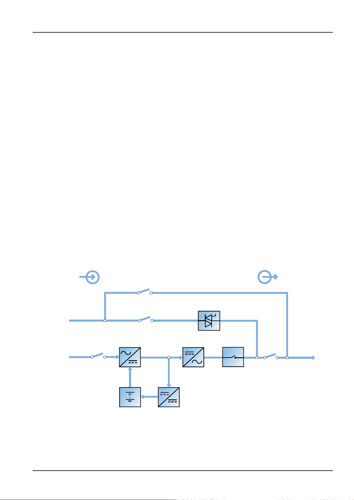
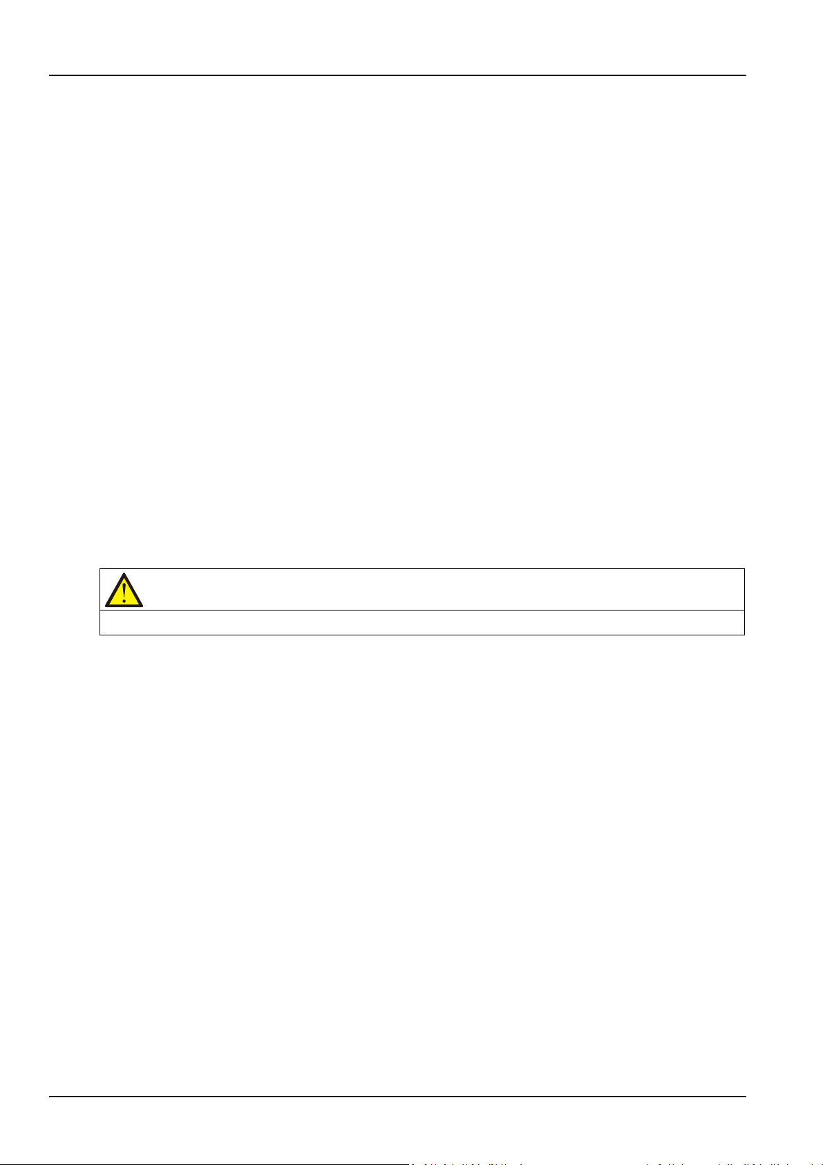
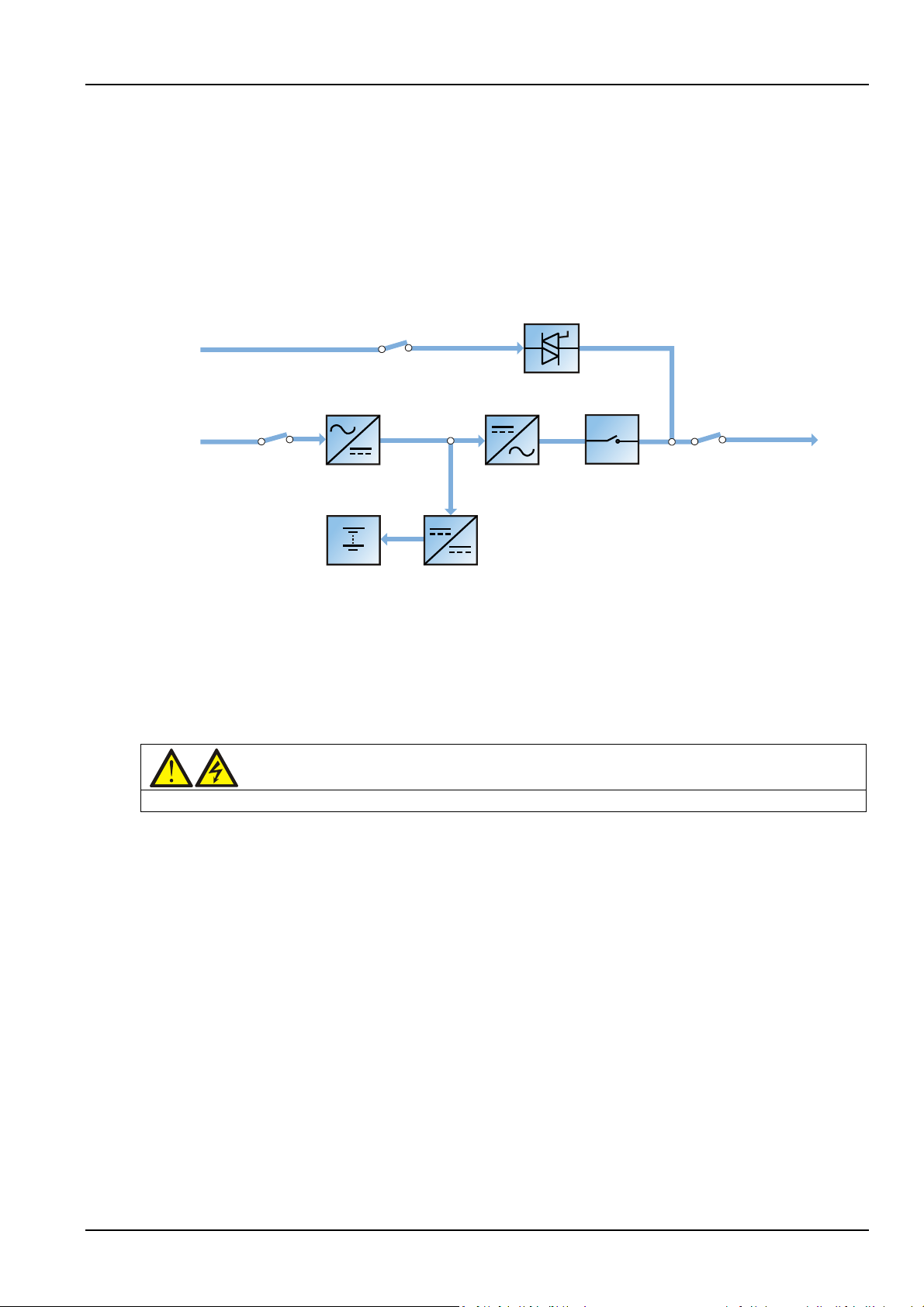
This section introduces the working principle of the UPS single module. The UPS adopts AC-DC-AC
converter (as shown in Figure 1-1). The first stage conversion (AC-DC) adopts three-phase high frequency
rectifier to convert the three-phase input voltage into stable DC bus voltage.
Figure 1-1 Block diagram for working principle of UPS single module
The UPS has its own battery charger and adopts advanced temperature compensation technology to
effectively prolong the battery service life. The inverter mainly adopts large power IGBT, and adopts
advanced SVPWM technology for control so as to invert the DC bus voltage back to AC voltage.
Liebert EXM 80kVA ~ 200kVA UPS User Manual
2 Chapter 1 Overview
Note
When the load is supplied by the bypass or maintenance bypass, the power supply quality will be uncertain.
When the mains is normal, the rectifier and inverter work together to supply the loads and charge the
battery.
When the mains is abnormal, the rectifier stops working, and the battery supplies power to the loads
through the inverter. If the battery voltage falls to end of discharge (EOD) voltage and the mains still has
not been recovered, the UPS will shut down (if the system uses split bypass configuration and the bypass
is normal, the system will transfer to bypass). The battery EOD voltage is preset. When the mains is
abnormal, the battery maintains the UPS operation till the battery voltage is reduced to EOD voltage and
the UPS shuts down, this time is called 'Backup Time'. The length of backup time depends on the battery
capacity and the loads.
1.2.2 Bypass
Through the intelligent control of the 'Static Switch' module (as shown in Figure 1-1) containing the
controllable electronic switch, the loads can be supplied by the inverter or the bypass. In normal situation,
the loads are supplied by the inverter, in which case the automatic inverter switch at inverter side is
closed. In the case of overload (the overload delay time expires) or inverter failure, the automatic inverter
switch is opened, and the 'Static Switch' module will automatically transfer the loads to the bypass.
In normal operating state, to realize the uninterrupted transfer between inverter and bypass, the inverter
output must be synchronized with the bypass.
Therefore, when the bypass frequency is within the synchronization range, the inverter control circuit will
synchronize the inverter output frequency with the bypass frequency and phase.
Besides, the UPS has a manual maintenance bypass switch for shutdown of the UPS upon maintenance. In
this situation, the bypass will directly supply the critical loads through the maintenance bypass.
1.2.3 System Control Principle
Normal operation
Normal mode: It means that the UPS has normal input mains, the rectifier and inverter operate normally,
the load is supplied by the inverter, the battery circuit breaker is closed, and the battery is in stable
floating charge state.
(Parallel System)
Note: As the UPS single module outputs are connected in parallel, the system checks
that the inverter control circuits are perfectly synchronized with one another and with the bypass in terms
of both frequency and phase, and that they have the same output voltages. Current supplied to the load is
automatically divided among UPSs. A warning message appears while synchronization is in progress.
Mains abnormal
When the mains fails or is abnormal, the rectifier will stop working automatically, and the system will
transfer to battery output (through inverter). The length of the operation time in battery mode depends
on the load and the battery capacity. During this period, if the battery voltage falls to the EOD voltage and
the mains still has not been recovered, the inverter will stop working automatically, and the UPS operator
control and display panel will display corresponding alarm messages. If the system uses split bypass
configuration and the bypass is normal, the system will transfer to bypass.
Liebert EXM 80kVA ~ 200kVA UPS User Manual

Chapter 1 Overview 3
Warning
If the UPS system is composed of two or more UPS modules, and when the load capacity exceeds the single
Mains recovery
When the mains resumes normal within allowable time, the rectifier will start automatically and supply the
load and charge the battery again. Therefore, the power supply to the load will not be interrupted.
Battery disconnection
To disconnect the external battery from the UPS system for maintenance, use the external isolating
switch. At this time, except for the battery backup function upon mains failure, other functions and all the
steady state performance of the UPS will not be affected.
UPS module failure
In case of inverter failure and output fuse blowout, the load will automatically transfer to the bypass, and
the output power supply will not be interrupted. In this situation, please contact the local customer service
center of Vertiv Tech Co., Ltd for technical support.
(Parallel System)
In the event of a fault in a UPS module, it will automatically exit from the parallel system.
If the system is still capable of providing the required load, the remaining modules will continue to supply
the load with no interruption. If the remaining modules are no longer capable of fulfilling the power
requirements, the load will automatically transfer to the bypass.
Overload
If the inverter is overloaded or the inverter current remains outside the specifications (refer to Table 11-6)
longer than the specified time, the load will automatically transfer to the bypass without power
interruption. If both the overload and the current are reduced to a level within the specified range, then
the load will be transferred back to the inverter. In case of output short circuit, the load will be transferred
to the bypass, and the inverter will shut down. Five minutes later, the inverter will start up automatically. If
the short circuit is removed at this point, the load will be transferred back to the inverter. The transfer is
determined first of all by the features of the protective device of the system.
In the above two situations, the UPS operator control and display panel will display alarm messages.
(Parallel System)
The control logic system constantly monitors load requirements and controls the power
supplied by each UPS module. In the event that an overload condition is sustained for greater than a
preset time, the load will transfer to the bypass, when the number of active modules is unable to satisfy
load requirements. The load returns to the inverter if the power is reduced to a value that can be
sustained by the number of active modules in the system.
Maintenance bypass
The UPS has a second bypass circuit, i.e. maintenance bypass, which provides a safe working environment
for the engineers to provide regular maintenance or repair to the UPS system and at the same time
provide unregulated mains supply to the loads. The maintenance bypass can be manually selected
through the maintenance bypass switch, and it can be disconnected by turning the switch to OFF.
module capacity, do not use the internal maintenance bypass switch.
1.2.4 UPS Power Supply Switch Configuration
The UPS has four switches: rectifier input switch Q1, bypass input switch Q2, maintenance bypass switch
Q3, and output switch Q5.
Note that switches Q1, Q2, and Q5 are optional.
Liebert EXM 80kVA ~ 200kVA UPS User Manual
4 Chapter 1 Overview
Note: Q1, Q2 and Q5 are optional while Q3 is standard.
Bypass input
Static switch
UPS
Output
UPS output
switch Q1
Rectifier
DC bus
Inverter
Inverter
Charger
Battery BCB
Mains input
of common input
Shorting copper bar
Neutral line input
Maintenance bypass switch Q3
Bypass input switch Q2
Rectifier input
switch
switch Q5
configuration
Figure 1-2 describes the block diagram of the UPS module. The UPS has split bypass configuration (that is,
the bypass adopts independent mains input) and common input configuration. If the system adopts
common input configuration, the UPS has shorting copper bar of common input configuration, and the
bypass input switch (Q2) and rectifier input switch (Q1) would be linked together. If the system adopts
split bypass configuartion, just remove the shorting copper bar of common input configuration of the UPS.
During the normal operation of the UPS, except for the maintenance bypass switch Q3, other switches
shall be closed.
Note: The mains input and bypass input share the same neutral line.
1.2.5 Battery Circuit Breaker (BCB)
The external battery shall be connected to the UPS through the BCB. The BCB box is an option, which
shall be installed near the battery. The BCB is closed manually. The BCB has a shunt tripping coil. When
the system is faulty and the BCB needs to be disconnected, the UPS control circuit will send a signal to
the shunt tripping coil so as to trip the BCB. It also has a magnetic trip facility for overload protection and
short circuit protection.
1.3 Parallel System
Up to four UPS modules can be parallel-connected to form a parallel system to increase the system
capacity and reliability. The load is equally shared between the paralleled UPS modules.
1.3.1 Parallel System Features
Moreover, two UPS modules or parallel system can comprise a dual bus system. Each parallel system has
independent output. Output synchronization is achieved through the LBS cable or LBS device, thus
enabling seamless load transfer between the two parallel systems or single modules through the STS
device.
1. The hardware and software of parallel system are completely the same as those of the single module.
The parallel system configuration is achieved through settings in configuration software.
2. Parallel cables are connected in a ring, providing both system reliability and redundancy.
Figure 1-2 UPS power supply switch configuration
Liebert EXM 80kVA ~ 200kVA UPS User Manual
3. The total load of the parallel system can be queried from each UPS module's TOUCHSCREEN.
Rectifier input switch
Mains input
Battery charger
Output switch
InverterRectifier
UPS output
Battery
Inverter switch
1.3.2 Parallel System Requirements
A group of paralleled modules behave as if it were one large UPS with the advantage of presenting higher
reliability. To ensure that all modules are equally utilised and to comply with relevant wiring rules, the
following requirements apply:
1. All UPS modules must be the same series, and connect to the same bypass source.
2. The N line of bypass and rectifier input sources must be connected to the same neutral line terminal.
3. Any RCD, if installed, must be of an appropriate setting and located upstream of the common neutral
line input terminal. Alternatively, the device must monitor the protective earth current of the system. Refer
to Warning: high earth leakage current before Contents.
4. For parallel system consists of two or more UPS modules, the bypass load sharing inductors (optional)
should be selected.
1.4 Operation Modes
The UPS has the following operation modes:
Chapter 1 Overview 5
Normal mode
Battery mode
Automatic restart mode
Bypass mode
Maintenance mode
ECO mode
Parallel redundancy mode (system expansion)
Frequency converter mode
LBS mode
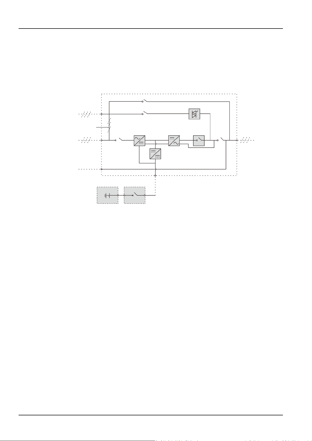
Normal mode
As shown in Figure 1-3, the mains is rectified by the UPS rectifier and then inverted by the inverter to
supply uninterrupted AC power to the loads. At the same time, the charger will charge the battery.
Figure 1-3 Schematic diagram of normal mode
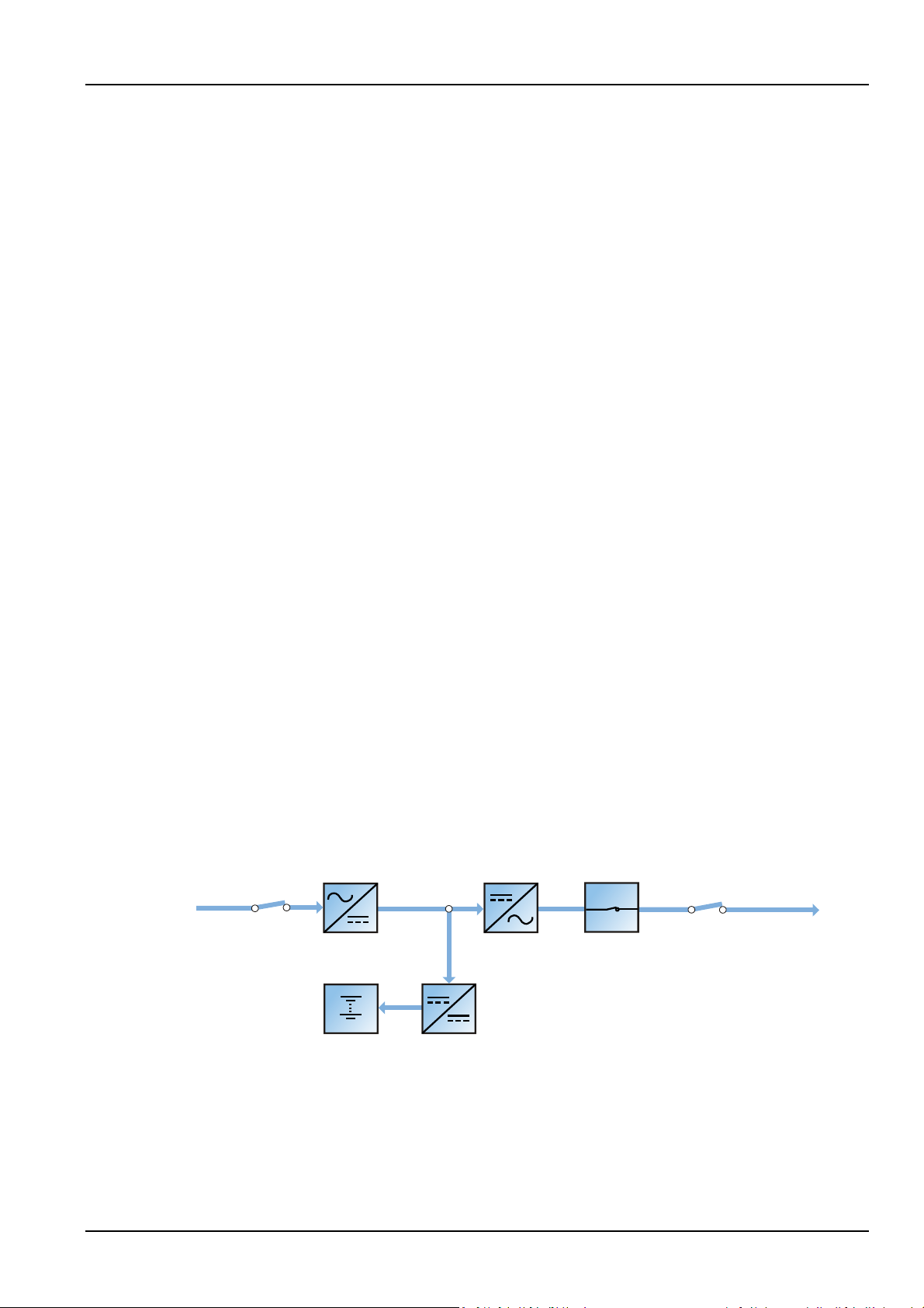
Battery mode
As shown in Figure 1-4, the operation mode in which the battery provides backup power supply to the
loads through the rectifier and inverter is called battery mode. Upon mains failure, the system will
automatically transfer to the battery mode with no load power interruption. When the mains is recovered,
Liebert EXM 80kVA ~ 200kVA UPS User Manual
6 Chapter 1 Overview
Output switch
Inverter
Rectifier
UPS output
Battery
Inverter switch
Bypass input switch
Bypass input
Static switch
Output switch
UPS output
Maintenance bypass switch
Bypass input
Maintenance bypass
UPS output
the system will automatically transfer back to the normal mode without any manual intervention, and the
power to the load will not be interrupted.
Note: Battery cold start function is available for switching the UPS on from Battery (charged) mode
directly during mains failure. Therefore, the battery power supply can be used independently to improve
the availability of the UPS.
Automatic restart mode
The UPS has automatic restart function. When the inverter shuts down because the mains fails and the
battery discharges to EOD voltage, if the mains is recovered, the UPS will restart automatically after a
certain time of delay. This function and the automatic restart type can be set by the service engineer
authorized by Vertiv.
Figure 1-4 Schematic diagram of battery mode
During the process of automatic restart time of delay, the UPS will charge the battery to protect against
the power-off risk of the load device caused by mains power failure.
If the automatic restart function has not been set, the user can manually start the UPS through Reset
Fault function.
Bypass mode
As shown in Figure 1-5, in normal mode, in case of an inverter failure, an inverter overload or an inverter
manual shutdown, the static switch will transfer the load from the inverter side to bypass side, with no
interruption in power to the load. At this time, if the inverter and bypass are not synchronized, the power
of the load has transitory interruption, with time of less than 20ms.
Figure 1-5 Schematic diagram of bypass mode
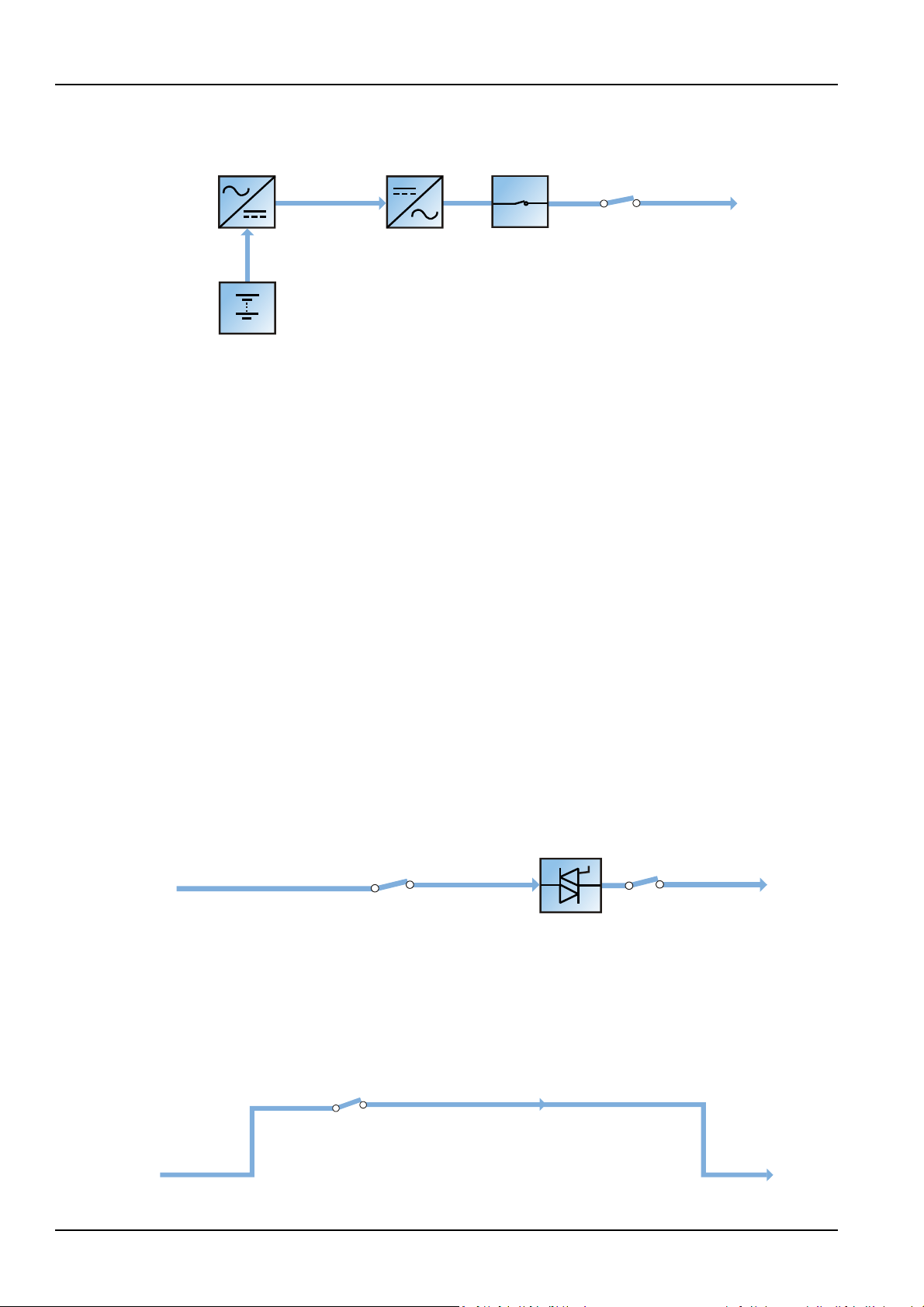
Maintenance mode
As shown in Figure 1-6, if the UPS maintenance or service is required, you may use the manual
maintenance bypass switch to transfer the load to maintenance bypass, with no interruption in power to
the load. This maintenance bypass switch is fitted in all UPS modules and rated for full load of a single
module.
Figure 1-6 Schematic diagram of maintenance mode
Liebert EXM 80kVA ~ 200kVA UPS User Manual
Chapter 1 Overview 7
Bypass input switch
Rectifier input switch
Bypass input
Mains input
Battery charger
Output switch
InverterRectifier
Static switch
UPS output
Battery
Inverter switch
Warning
In ECO mode, the load is not protected against mains distortion.
ECO mode
If ECO mode is selected, all power switches and the battery switches are closed except for the
maintenance bypass switch, and the system prefers to put the load on the bypass, to achieve the aim of
energy-saving. When the bypass supply is within the range of normal frequency and normal voltage
(adjustable), the load is powered by the bypass, with the inverter on stand-by; when the voltage and/or
frequency of the bypass supply are beyond the pre-defined and adjustable limits, the system will transfer
to the inverter output, and the transfer time for switching from bypass to inverter is less than 2ms
(uninterrupted) and less than 5ms (interrupted). In this mode, the system can normally charge the battery.
Figure 1-7 Schematic diagram of ECO mode
If ECO mode is required, adjust corresponding parameters through the operator control and display panel.
The operation method of ECO mode is the same as the description in Chapter 5 UPS Operation
Introduction. However, in normal mode, the load is powered by the bypass, the TOUCHSCREEN displays
'Bypass mode', and the transfer time for switching from bypass to inverter is less than 2ms (uninterrupted)
and less than 5ms (interrupted).
Parallel redundancy mode (system expansion)
For higher capacity or higher reliability, the outputs of multiple UPS modules can be programmed for
directly paralleling while a built-in parallel controller in each UPS module ensures automatic load sharing.
The parallel system can be composed of up to four UPS modules. For the operation principle diagram of
the parallel redundancy mode, see Figure 7-1.
Frequency converter mode
The UPS can be programmed into frequency converter mode for either 50Hz or 60Hz stable output
frequency. The input frequency may vary from 40Hz to 70Hz. Under this mode, it is required to open the
maintenance bypass switch to disable the static bypass operation, and the battery becomes optional
depending on any requirement to operate in battery mode.
LBS mode
A dual bus system consists of two independent UPS systems, each containing one or more parallel UPS
modules. The dual bus system has high reliability and is applicable to the load with multiple inputs. For
Liebert EXM 80kVA ~ 200kVA UPS User Manual

8 Chapter 1 Overview
single-input load, an STS can be installed to power the load. For the operation principle diagram of the
LBS mode, see Figure 7-5 and Figure 7-6.
1.5 Battery Management
The following battery management functions are set by the service engineer through the Vertiv setting
software.
1.5.1 Normal Function
1. Constant current boost charge
Adopt the constant current (within battery charging limit) to charge the battery. The function can be used
for battery capacity fast recovery. The charge current can be set.
2. Constant voltage boost charge
Adopt the constant voltage to charge battery. The function can be used for battery capacity fast recovery.
For VRLA batteries, the maximum boost charge voltage should not exceed 2.4V/cell.
3. Float charge
The charging method is used for keeping battery with a full capacity. The float charge voltage is generally
low. The function can balance the capacity loss due to battery self discharging, and can be used for
battery capacity recovery.
For VRLA batteries, the float charge voltage should be between 2.2V/cell and 2.3V/cell.
4. Automatic transfer to float charge
When the charge current is less than 'Threshold of Equalize Charge to Float Charge' or 0.5A, the charger
will automatically transfer from boost charge to float charge. When boost charge time exceeds the limit of
'Equalize Charge Protect Time Limit', the charger will be forcibly transferred to float charge for protecting
the battery.
5. Float charge temperature compensation (optional)
This function must be used together with the battery temperature detection device. The Vertiv battery
temperature sensor is a standard option for your selection.
6. EOD protection
When the battery voltage drops to the EOD voltage, the battery converter shuts down automatically and
the battery is inhibited to avoid further battery discharge. The EOD voltage is settable from 1.60V/cell to
1.90V/cell (VRLA).
7. Battery low pre-warning time
The battery low pre-warning time is adjustable between 3min and 60min. The default setting is 5min.
8. Maximum battery discharge time
When the battery has small current discharge for a long time, the battery is over discharged and even has
unrecoverable damage, thus setting a battery discharge time to protect the battery is essential. The limit
of time setting shall be configured by service engineer through the Vertiv setting software.
9. Maximum boost charge protection time
To protect against the battery overcharge damage caused by long time boost charge, a protect time
setting is essential. The limit of time setting shall be configured by service engineer through the Vertiv
setting software.
Liebert EXM 80kVA ~ 200kVA UPS User Manual

1.5.2 Advanced Function
The UPS provides battery maintenance test function. At periodic intervals, 20% of the rated capacity of
the battery will be discharged automatically, and the actual three-phase load must exceed 20% of the
nominal UPS capacity. If the load is less than 20%, the automatic discharge cannot be executed. The
periodic interval can be set from 30 to 360 days. The battery maintenance test function can be disabled
through the Vertiv setting software.
Conditions: Battery at float charge for at least 5h, load equal to 20% ~ 100% of rated UPS capacity.
Trigger: Automatically, or manually through the command of battery maintenance test in
TOUCHSCREEN.
Interval: 30 ~ 360 days (default setting: 60 days).
The UPS also provides battery capacity self-test function: Periodically test the battery activity, test the
battery residual capacity, judge the battery quality, and then provide corresponding measures. The
capacity self-test is started by the user through the operator control and display panel. During the
capacity self-test, the battery will continuously discharge to the battery undervoltage shutdown threshold.
After the self-test is finished, the system will update the battery curve table. The capacity self-test
command is valid only one time, without any memory. During the capacity self-test, if the battery
maintenance requirement is satisfied, the system will generate audible/visual alarm and give
corresponding records.
Chapter 1 Overview 9
Conditions: System load rate within 20% ~ 100%, battery float charge at least 5h, and generator not
connected; the current system is in float charge state.
Liebert EXM 80kVA ~ 200kVA UPS User Manual
10 Chapter 1 Overview
Warning
The user must select an appropriate MCCB to protect against short circuit and overload for the battery. It is
Trigger: Start up through the TOUCHSCREEN.
Note:
1. The battery will continuously discharge to the battery undervoltage shutdown threshold, then the
battery transfer to the charging state. When the capacity self-test is finished, the system will update the
battery curve table.
2. The user can manually stop the capacity self-test operation through the TOUCHSCREEN.
1.5.3 Battery Temperature Compensation
The UPS system has battery charge temperature compensation function. When the ambient temperature
is increased, the DC bus voltage (which charges the battery) will be reduced correspondingly to provide
optimal charging voltage for the battery, thus prolonging the battery service life time.
This function must be used together with the Vertiv battery temperature detection device (a standard
option).
1.6 Battery Protection
recommended to adopt Vertiv BCB to provide a better solution.
The following battery protection functions are set by the service engineer through the Vertiv setting
software.
Battery low pre-warning
The battery low pre-warning occurs before the EOD. After this pre-warning, the battery should have the
capacity for three remaining minutes discharging with full load. The time can be configured from 3min to
60min.
EOD protection
When the battery voltage drops to the EOD voltage, the battery converter shuts down automatically. For
VRLA batteries, the EOD voltage is adjustable from 1.60V/cell to 1.90V/cell (VRLA).
BCB alarm
The BCB alarm occurs when the external BCB opens, if you select the Vertiv BCB (optional).
The external battery connects to the UPS through the BCB. The BCB is manually closed and tripped by
the UPS control circuit.
Liebert EXM 80kVA ~ 200kVA UPS User Manual
Chapter 2 Mechanical Installation
Warning: professional installation required
1. Do not disassemble the package without permission of authorized service engineer.
Warning
The UPS can be connected to IT, TN and TT AC distribution systems (IEC60364-3), and must be of 3-phase 5-wire
Warning: battery danger
Take special care when installing batteries. When connecting batteries, the battery terminal voltage will reach
This chapter briefly introduces the mechanical installation of the UPS, including the precautions, initial
inspection before installation, environmental requirement, mechanical requirement and installation
diagram.
2.1 Precautions
This chapter describes the environmental and mechanical requirements and mechanical considerations
that must be taken into account when planning the positioning and cabling of the UPS equipment.
Because each site has its particular characteristics, this chapter does not provide the detailed installation
steps, it only acts as a guide for the general procedures and practices that should be observed by the
installing engineer, so that they can properly handle the specific situation of the site.
Chapter 2 Mechanical Installation 11
2. The UPS should be installed by an authorized engineer in accordance with the information contained in this
chapter.
(A, B, C, N, PE) system.
320Vdc, which is fatal to human being.
1. Please wear safety glasses to protect the eyes from being damaged by arc.
2. Remove all the metal items, including finger rings, watch, etc.
3. Use tools with insulated handle.
4. Wear rubber gloves.
5. If the battery has electrolyte leakage or the battery is damaged, it must be replaced. Place the battery into the
container that can withstand sulfuric acid and dispose of it according to the local regulations.
6. If the skin contacts the electrolyte, flush it with water immediately.
2.2 Transportation
Railroad transportation and shipping are the recommended means of transportation. If truck
transportation is unavoidable, choose roads that are less bumpy in order to protect the equipment.
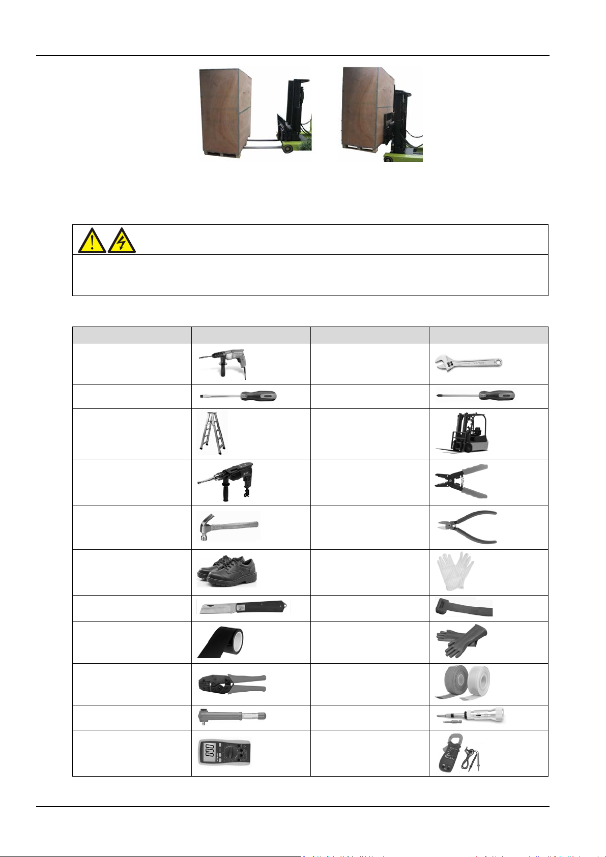
The UPS cabinet is heavy (see Table 11-3 for its weight). It is recommended to use mechanical equipment
such as an electric forklift to unload and move the equipment to the place closest to the installation site. If
an electric forklift is used, insert the tines of the forklift below the bottom pallet (as shown in Figure 2-1) to
prevent the equipment from falling over.
Liebert EXM 80kVA ~ 200kVA UPS User Manual
12 Chapter 2 Mechanical Installation
Warning
1. For the sake of safety, the installation tools under live operation must be insulated.
Name
Drawing
Name
Drawing
2.3 Tools
2. Tools in Table 2-1 are for reference only; please follow the actual requirement for on-site installation and
connection.
Figure 2-1 Inserting and movement
Table 2-1
Tools
Electric hand drill
Slotted screwdriver
Stepladder
Drill
Claw hammer
Insulating shoes
Electrician knife
Insulating tape
Adjustable wrench
Cross head screwdriver
Forklift
Wire cutting plier
Diagonal cutting plier
Antistatic gloves
Cable tie
Insulating gloves
Crimping plier
Insulated torque wrench
Multimeter
Liebert EXM 80kVA ~ 200kVA UPS User Manual
Heat shrinkable tube
Torque screwdriver
Clip-on ammeter
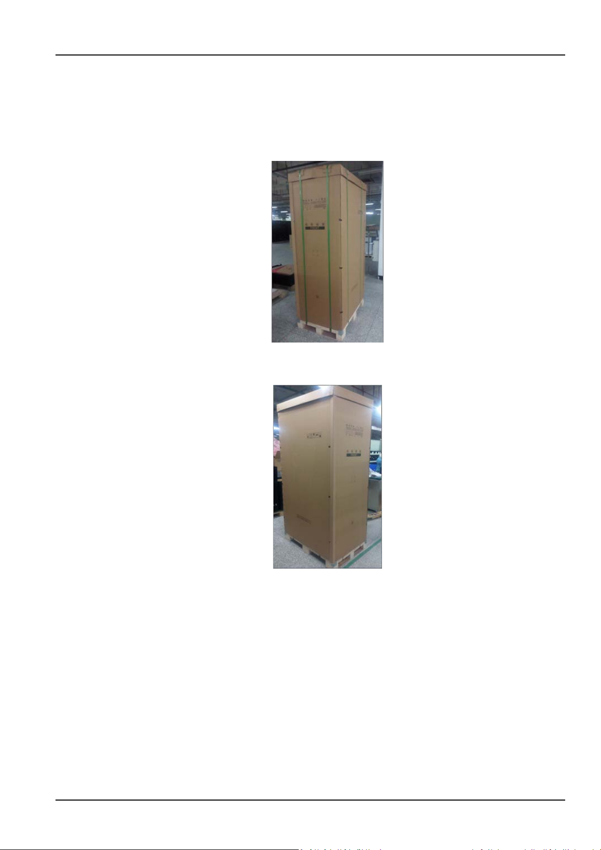
2.4 Unpacking
Unpack the UPS and battery packages under the guidance of authorized service engineer. Steps:
1. Remove the packing belt.
Use a cutting plier to cut off the packing belt, as shown in Figure 2-2.
Chapter 2 Mechanical Installation 13
Figure 2-2 Packing belt
As shown in Figure 2-3, remove the top cover and carton box.
Figure 2-3 Removing top cover and carton box
2. As shown in Figure 2-4, remove the honey comb plate.
Liebert EXM 80kVA ~ 200kVA UPS User Manual
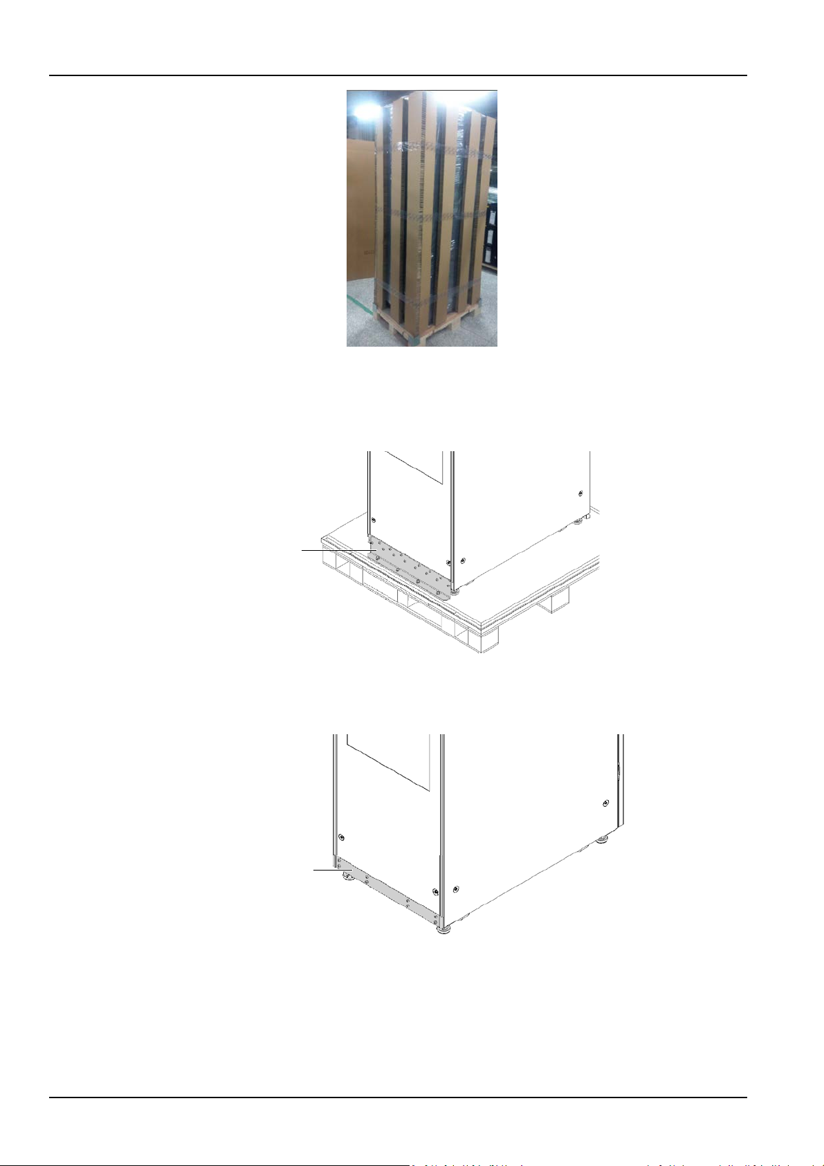
14 Chapter 2 Mechanical Installation
Fixed part
Rear view
Decorative plate
Rear view
3. Open the front door of the UPS, loosen the fixing screws and remove the bottom fixed part at front of
the cabinet. Then loosen the fixing screws and remove the bottom fixed part at back of the cabinet. As
shown in Figure 2-5.
Figure 2-4 Removing honey comb plate
Figure 2-5 Removing bottom fixed part
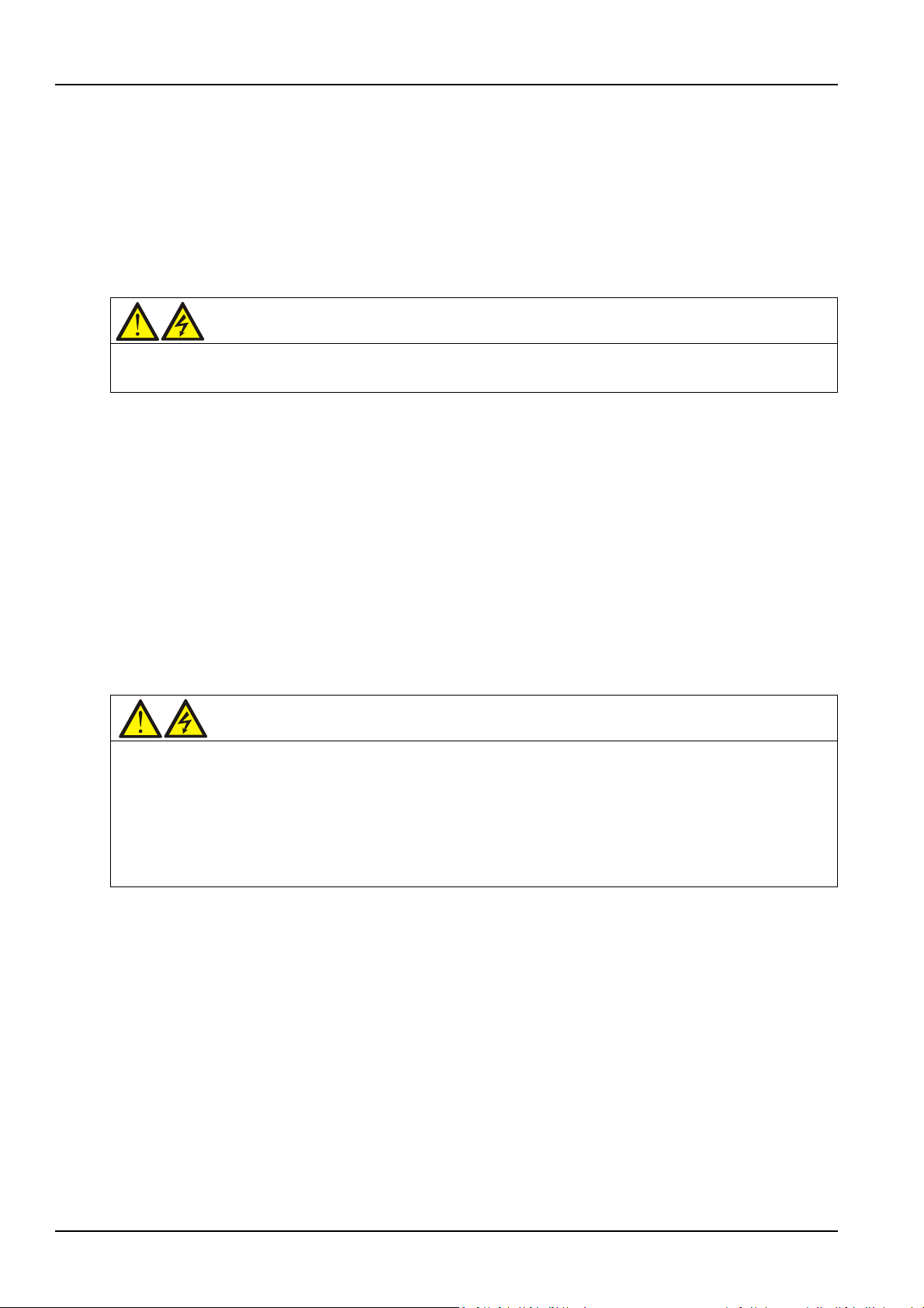
4. Refer to Figure 2-6, install the decorative plate at the position of the removed fixed part.
Figure 2-6 Installing decorative plate
5. Raise the four feet, push down the cabinet along the slide board and move it to its installation position.
Then lower the four feet to fix the cabinet.
Liebert EXM 80kVA ~ 200kVA UPS User Manual

2.5 Initial Inspection
Before installing the UPS, carry out the following inspections:
1. Ensure that the environment of the UPS equipment room meets the environmental requirement
specified in the product technical specifications, especially the ambient temperature, ventilation
conditions, and the dust situations.
2. Unpack the UPS and battery under the guidance of authorized service engineer. Visually inspect
whether the UPS and battery have any transportation damage. If there is any damage, report to the carrier
immediately.
3. Verify the UPS label and confirm the correctness of the UPS. The UPS label is attached on the back of
the door. The model, capacity and main parameters of the UPS are marked on the label.
2.6 Environmental Requirement
2.6.1 UPS Location Selection
The UPS should be located in a cool, dry, clean-air indoor environment with adequate ventilation, and
should be located on concrete or other nonflammable and flat surfaces. The ambient environment should
be free of conductive powder (such as metallic powder, sulfide, sulfur dioxide, graphite, carbon fiber,
conductive fiber, etc.), acid mist or other conductive media (strongly ionized substances). The
environment specifications should comply with relevant international standard & specifications and the
operating range (see Table 11-2) specified in this manual.
Chapter 2 Mechanical Installation 15
The UPS uses forced cooling by internal fans. Cooling air enters the UPS through the ventilation grills at
the front of the cabinet and exhausted through the ventilation grills at the back of the cabinet. Do not
obstruct the ventilation holes (ventilation grills). The rear of the UPS should be kept a distance at least
500mm from the wall to avoid blocking the UPS heat dissipation, thus reducing the UPS internal
temperature and improving the UPS life.
If necessary, install indoor extractor fans to aid cooling-air flow to avoid room temperature buildup. Air
filters (optional) should be used when the UPS is to operate in a dirty environment.
Note 1: When the battery cabinet is installed near the UPS, the maximum allowable ambient
temperature is dependent on the battery rather than the UPS.
Note 2: If the UPS is working in ECO mode, the power consumption will be less than that in Normal
mode. Proper air conditioning system shall be selected according to the normal operating mode.
2.6.2 Battery Location Selection
Batteries generate some amount of hydrogen and oxygen at the end of charge, so the fresh air volume of
the battery installation environment must meet the EN50272-2001 requirements.
The ambient temperature is the main factor that affects the battery capacity and life. The normal
operating temperature of the battery is 20°C. If the ambient temperature is higher than 20°C, the battery
life will be reduced. If it is lower than 20°C, the battery capacity will be reduced. In normal situation, the
allowable ambient temperature for the battery is 15°C to 25°C. The ambient temperature of the battery
shall be maintained constant, and the battery shall be kept away from heat source and air outlet.
Battery can be installed inside the specialized battery cabinet which shall be close to the UPS. If the
battery is placed on the raised floor, bracket shall be installed under the floor, just as for the UPS. If the
Liebert EXM 80kVA ~ 200kVA UPS User Manual
16 Chapter 2 Mechanical Installation
Warning
During battery storage, periodically charge the battery according to the battery manufacturer instructions. In the
Warning
1. The lifting equipment for moving the UPS cabinet must have enough lift capacity.
battery adopts rack mounting or is mounted far from the UPS with other installation mode, the battery
circuit breaker shall be installed near the battery, and the cabling distance shall be minimized.
2.6.3 Storage
Should the UPS not be installed immediately, it must be stored with the original packaging in a room for
protection against excessive humidity and heat sources (see Table 11-2). The battery needs to be stored
in a dry and cool place with good ventilation. The most suitable storage temperature ranges from 20°C to
25°C.
charge process, temporarily connect the UPS to the mains and activate the battery by recharging the battery.
2.7 Mechanical Requirement
2.7.1 Composition
As a cabinet of 600mm width, the 80kVA ~ 120kVA system provides the options such as rectifier input
switch, bypass input switch, and output switch.
As a cabinet of 600mm width, the 160kVA ~ 200kVA system also provides the optional switch cabinet
(width: 400mm) which contains the rectifier input switch, bypass input switch, output switch and
maintenance switch.
2.7.2 Moving Cabinet
2. The UPS has installed castors. When removing the UPS from the shipping pallet, pay attention to keeping the
UPS from sliding. Ensure that adequate personnel and lifting equipment are available when removing the shipping
pallet.
3. Due to its intensity, the castor may not be valid on the uneven surface.
4. The center of gravity of the UPS cabinet is high; avoid falling over during the cabinet movement.
5. Vertical hanging of cabinet is not allowed.
Ensure that the weight of the UPS does not exceed the capacity of the lifting equipment. For the UPS
weight, refer to Table 11-3.
The UPS cabinet can be moved by forklift or other similar lifting equipment.
For short distance movement, the castors can be used.
2.7.3 Clearance
Because the UPS has no grille at the two sides, there is no special clearance requirement on the two sides.
Besides the local regulations, to enable routine tightening of the power terminals within the UPS, it is
recommended that clearance around the front of the UPS should be sufficient to enable free passage of
personnel with the door fully open. Meanwhile, maintain at the back of the cabinet a clearance at least
500mm to permit adequate circulation of air coming out of the UPS.
Liebert EXM 80kVA ~ 200kVA UPS User Manual
 Loading...