

Vertiv Liebert EXM External Battery Cabinet, Liebert EXM 480V User Manual

Liebert®
EXM™ External Battery Cabinet
User Manual

The information contained in this document is subject to change
without notice and may not be suitable for all applications. While
every precaution has been taken to ensure the accuracy and
completeness of this document, Vertiv assumes no responsibility
and disclaims all liability for damages resulting from use of this
information or for any errors or omissions. Refer to other local
practices or building codes as applicable for the correct methods,
tools, and materials to be used in performing procedures not
specifically described in this document.
The products covered by this instruction manual are manufactured
and/or sold by Vertiv This document is the property of Vertiv and
contains confidential and proprietary information owned by Vertiv.
Any copying, use or disclosure of it without the written permission of
Vertiv is strictly prohibited.
Names of companies and products are trademarks or registered
trademarks of the respective companies. Any questions regarding
usage of trademark names should be directed to the original
manufacturer.
Technical Support Site
If you encounter any installation or operational issues with your product, check the pertinent
section of this manual to see if the issue can be resolved by following outlined procedures.
Visit https://www.VertivCo.com/en-us/support/ for additional assistance.

TABLE OF CONTENTS
IMPORTANT SAFETY INSTRUCTIONS . . . . . . . . . . . . . . . . . . . . . . . . . . . . . . . . . . . . . . 1
SAVE THESE INSTRUCTIONS . . . . . . . . . . . . . . . . . . . . . . . . . . . . . . . . . . . . . . . . . . . . . . . 1
1.0 MECHANICAL INSTALLATION . . . . . . . . . . . . . . . . . . . . . . . . . . . . . . . . . . . . . . . . 5
1.1 Introduction. . . . . . . . . . . . . . . . . . . . . . . . . . . . . . . . . . . . . . . . . . . . . . . . . . . . . . . . . . . . . . . . . . . . . . . . . . . . . . 5
1.2 System Composition. . . . . . . . . . . . . . . . . . . . . . . . . . . . . . . . . . . . . . . . . . . . . . . . . . . . . . . . . . . . . . . . . . . . . 5
1.3 Preliminary Checks . . . . . . . . . . . . . . . . . . . . . . . . . . . . . . . . . . . . . . . . . . . . . . . . . . . . . . . . . . . . . . . . . . . . . . 5
1.4 Environmental Considerations. . . . . . . . . . . . . . . . . . . . . . . . . . . . . . . . . . . . . . . . . . . . . . . . . . . . . . . . . . . 5
1.4.1 Battery Room. . . . . . . . . . . . . . . . . . . . . . . . . . . . . . . . . . . . . . . . . . . . . . . . . . . . . . . . . . . . . . . . . . . . . . . . . . . . . 5
1.4.2 Storing Batteries for Delayed Installation . . . . . . . . . . . . . . . . . . . . . . . . . . . . . . . . . . . . . . . . . . . . . . . . 6
1.4.3 Installation Considerations . . . . . . . . . . . . . . . . . . . . . . . . . . . . . . . . . . . . . . . . . . . . . . . . . . . . . . . . . . . . . . . 6
1.5 Moving the Battery Cabinets . . . . . . . . . . . . . . . . . . . . . . . . . . . . . . . . . . . . . . . . . . . . . . . . . . . . . . . . . . . . 7
1.5.1 Raised Floor Mounting . . . . . . . . . . . . . . . . . . . . . . . . . . . . . . . . . . . . . . . . . . . . . . . . . . . . . . . . . . . . . . . . . . . 7
1.6 Layout . . . . . . . . . . . . . . . . . . . . . . . . . . . . . . . . . . . . . . . . . . . . . . . . . . . . . . . . . . . . . . . . . . . . . . . . . . . . . . . . . . . 8
1.6.1 Connecting the Liebert EXM Battery Cabinet to the UPS . . . . . . . . . . . . . . . . . . . . . . . . . . . . . . . . 9
2.0 BATTERY INSTALLATION . . . . . . . . . . . . . . . . . . . . . . . . . . . . . . . . . . . . . . . . . . . . 11
2.1 Safety . . . . . . . . . . . . . . . . . . . . . . . . . . . . . . . . . . . . . . . . . . . . . . . . . . . . . . . . . . . . . . . . . . . . . . . . . . . . . . . . . . . 11
2.1.1 Connecting the Batteries. . . . . . . . . . . . . . . . . . . . . . . . . . . . . . . . . . . . . . . . . . . . . . . . . . . . . . . . . . . . . . . . 12
2.2 Power Connection . . . . . . . . . . . . . . . . . . . . . . . . . . . . . . . . . . . . . . . . . . . . . . . . . . . . . . . . . . . . . . . . . . . . . . 12
2.2.1 Connected System . . . . . . . . . . . . . . . . . . . . . . . . . . . . . . . . . . . . . . . . . . . . . . . . . . . . . . . . . . . . . . . . . . . . . . 12
2.2.2 Stand-Alone and Right-Mounted Systems. . . . . . . . . . . . . . . . . . . . . . . . . . . . . . . . . . . . . . . . . . . . . . 12
2.2.3 Attached/Detached System. . . . . . . . . . . . . . . . . . . . . . . . . . . . . . . . . . . . . . . . . . . . . . . . . . . . . . . . . . . . . 13
2.2.4 Grounding . . . . . . . . . . . . . . . . . . . . . . . . . . . . . . . . . . . . . . . . . . . . . . . . . . . . . . . . . . . . . . . . . . . . . . . . . . . . . . . 13
2.3 Control Connection . . . . . . . . . . . . . . . . . . . . . . . . . . . . . . . . . . . . . . . . . . . . . . . . . . . . . . . . . . . . . . . . . . . . . 13
2.4 Non-Standard Batteries. . . . . . . . . . . . . . . . . . . . . . . . . . . . . . . . . . . . . . . . . . . . . . . . . . . . . . . . . . . . . . . . . 14
2.5 Batteries Approved for Use in Liebert EXM Systems . . . . . . . . . . . . . . . . . . . . . . . . . . . . . . . . . . . 18
2.5.1 Floor Installation. . . . . . . . . . . . . . . . . . . . . . . . . . . . . . . . . . . . . . . . . . . . . . . . . . . . . . . . . . . . . . . . . . . . . . . . . 18
2.5.2 Cable Entry . . . . . . . . . . . . . . . . . . . . . . . . . . . . . . . . . . . . . . . . . . . . . . . . . . . . . . . . . . . . . . . . . . . . . . . . . . . . . . 18
2.6 Static Bypass Assembly . . . . . . . . . . . . . . . . . . . . . . . . . . . . . . . . . . . . . . . . . . . . . . . . . . . . . . . . . . . . . . . . 19
2.7 Control Wiring . . . . . . . . . . . . . . . . . . . . . . . . . . . . . . . . . . . . . . . . . . . . . . . . . . . . . . . . . . . . . . . . . . . . . . . . . . 19
2.7.1 Battery Cabinet Interface Connectors. . . . . . . . . . . . . . . . . . . . . . . . . . . . . . . . . . . . . . . . . . . . . . . . . . . 19
2.8 Alber BDSUi™ Battery Monitoring System—Optional . . . . . . . . . . . . . . . . . . . . . . . . . . . . . . . . . . .23
2.9 Connecting an Alber
2.9.1 Accessory Fuses and Back-Feed Breaker Wiring. . . . . . . . . . . . . . . . . . . . . . . . . . . . . . . . . . . . . . . .26
2.10 Battery Protection . . . . . . . . . . . . . . . . . . . . . . . . . . . . . . . . . . . . . . . . . . . . . . . . . . . . . . . . . . . . . . . . . . . . . .26
2.10.1 Battery Undervoltage Warning . . . . . . . . . . . . . . . . . . . . . . . . . . . . . . . . . . . . . . . . . . . . . . . . . . . . . . . . . . 26
2.10.2 Battery End-of-Discharge (EOD) Protection . . . . . . . . . . . . . . . . . . . . . . . . . . . . . . . . . . . . . . . . . . . .26
®
BDSUi-UXBM/50™. . . . . . . . . . . . . . . . . . . . . . . . . . . . . . . . . . . . . . . . . . . . . . . .24
3.0 INSTALLATION DRAWINGS . . . . . . . . . . . . . . . . . . . . . . . . . . . . . . . . . . . . . . . . . .27
4.0 SPECIFICATIONS . . . . . . . . . . . . . . . . . . . . . . . . . . . . . . . . . . . . . . . . . . . . . . . . . . . . . 31
5.0 MAINTENANCE . . . . . . . . . . . . . . . . . . . . . . . . . . . . . . . . . . . . . . . . . . . . . . . . . . . . . .35
5.1 Record Log. . . . . . . . . . . . . . . . . . . . . . . . . . . . . . . . . . . . . . . . . . . . . . . . . . . . . . . . . . . . . . . . . . . . . . . . . . . . . .35
5.2 Battery Maintenance . . . . . . . . . . . . . . . . . . . . . . . . . . . . . . . . . . . . . . . . . . . . . . . . . . . . . . . . . . . . . . . . . . .35
5.3 Battery Safety Precautions . . . . . . . . . . . . . . . . . . . . . . . . . . . . . . . . . . . . . . . . . . . . . . . . . . . . . . . . . . . . .36
5.4 Torque Requirements. . . . . . . . . . . . . . . . . . . . . . . . . . . . . . . . . . . . . . . . . . . . . . . . . . . . . . . . . . . . . . . . . . .38
Vertiv | Liebert® Battery Cabinet User Manual | i

FIGURES
Figure 1 Battery cabinets connected, attached to UPS . . . . . . . . . . . . . . . . . . . . . . . . . . . . . . . . . . . . . . .8
Figure 2 Bolting the Liebert EXM Battery Cabinet to the Liebert EXM UPS . . . . . . . . . . . . . . . . . . . 9
Figure 3 Power cabling for 140-200kVA UPS. . . . . . . . . . . . . . . . . . . . . . . . . . . . . . . . . . . . . . . . . . . . . . . . . 10
Figure 4 Battery cabinet terminal detail, 320mm cabinet; 10-40kVA UPS. . . . . . . . . . . . . . . . . . . . 14
Figure 5 Battery cabinet terminal detail, 600mm and 880mm cabinet; 10-120kVA UPS . . . . . 15
Figure 6 Liebert EXM UPS terminal detail 10-40kVA . . . . . . . . . . . . . . . . . . . . . . . . . . . . . . . . . . . . . . . . .16
Figure 7 Liebert EXM UPS terminal detail 60-100kVA . . . . . . . . . . . . . . . . . . . . . . . . . . . . . . . . . . . . . . . 17
Figure 8 Static Bypass Assembly connections . . . . . . . . . . . . . . . . . . . . . . . . . . . . . . . . . . . . . . . . . . . . . . . 19
Figure 9 Single battery cabinet connection to Liebert EXM . . . . . . . . . . . . . . . . . . . . . . . . . . . . . . . . . .20
Figure 10 Alber BDSUi-UXCM rear panel . . . . . . . . . . . . . . . . . . . . . . . . . . . . . . . . . . . . . . . . . . . . . . . . . . . . . .23
Figure 11 Alber BDSUi-UXBM/50 rear panel . . . . . . . . . . . . . . . . . . . . . . . . . . . . . . . . . . . . . . . . . . . . . . . . . .24
Figure 12 Alber® battery cabinet monitoring assembly diagram. . . . . . . . . . . . . . . . . . . . . . . . . . . . . . .25
Figure 13 Accessory fuses. . . . . . . . . . . . . . . . . . . . . . . . . . . . . . . . . . . . . . . . . . . . . . . . . . . . . . . . . . . . . . . . . . . . .26
Figure 14 Battery cabinet outline and main components—320mm cabinet . . . . . . . . . . . . . . . . . . . 27
Figure 15 Battery cabinet outline drawing and main components—600mm cabinet. . . . . . . . . .28
Figure 16 Battery cabinet outline and main components—880mm cabinet . . . . . . . . . . . . . . . . . . .29
Figure 17 Lineup arrangement, Liebert EXM with battery and Liebert BDC . . . . . . . . . . . . . . . . . . .30
Figure 18 Battery, circuit breaker and UPS wiring with external batteries with three connecting
wires34
TAB LES
Table 1 Control wiring for Liebert EXM to battery cabinet . . . . . . . . . . . . . . . . . . . . . . . . . . . . . . . . . . 10
Table 2 Interconnect wiring for UPS to battery cabinet . . . . . . . . . . . . . . . . . . . . . . . . . . . . . . . . . . . . . 15
Table 3 Batteries approved for use in Liebert EXM External Battery Cabinet, 320mm . . . . . . 18
Table 4 Batteries approved for use in Liebert EXM External Battery Cabinet, 600mm. . . . . . 18
Table 5 Batteries approved for use in Liebert EXM External Battery Cabinet, 880mm . . . . . . 18
Table 6 Battery cabinet interface—J22. . . . . . . . . . . . . . . . . . . . . . . . . . . . . . . . . . . . . . . . . . . . . . . . . . . . . . 19
Table 7 Battery voltage, nominal and float. . . . . . . . . . . . . . . . . . . . . . . . . . . . . . . . . . . . . . . . . . . . . . . . . . . 21
Table 8 Alber UXCM rear panel features. . . . . . . . . . . . . . . . . . . . . . . . . . . . . . . . . . . . . . . . . . . . . . . . . . . . .23
Table 9 Alber UXCM rear panel features. . . . . . . . . . . . . . . . . . . . . . . . . . . . . . . . . . . . . . . . . . . . . . . . . . . . .24
Table 10 Total width of additional battery cabinets and bypass cabinet . . . . . . . . . . . . . . . . . . . . .30
Table 11 Physical standards and parameters. . . . . . . . . . . . . . . . . . . . . . . . . . . . . . . . . . . . . . . . . . . . . . . . . 31
Table 12 Battery cabinet system - breaker details . . . . . . . . . . . . . . . . . . . . . . . . . . . . . . . . . . . . . . . . . . . . 31
Table 13 Battery cabinet system—UPS and Liebert EXM Battery Cabinet . . . . . . . . . . . . . . . . . . . 31
Table 14 Battery DC intermediate circuit . . . . . . . . . . . . . . . . . . . . . . . . . . . . . . . . . . . . . . . . . . . . . . . . . . . . . 32
Table 15 Battery short circuit currents . . . . . . . . . . . . . . . . . . . . . . . . . . . . . . . . . . . . . . . . . . . . . . . . . . . . . . .32
Table 16 600mm battery cabinet mechanical characteristics . . . . . . . . . . . . . . . . . . . . . . . . . . . . . . . .33
Table 17 880mm battery cabinet mechanical characteristics . . . . . . . . . . . . . . . . . . . . . . . . . . . . . . . .33
Table 18 320mm battery cabinet mechanical characteristics . . . . . . . . . . . . . . . . . . . . . . . . . . . . . . . .33
Table 19 Busbars (for power wiring) . . . . . . . . . . . . . . . . . . . . . . . . . . . . . . . . . . . . . . . . . . . . . . . . . . . . . . . . . .38
Table 20 Terminal block with compression lugs (for control wiring) . . . . . . . . . . . . . . . . . . . . . . . . . .38
Table 21 Battery retorque values . . . . . . . . . . . . . . . . . . . . . . . . . . . . . . . . . . . . . . . . . . . . . . . . . . . . . . . . . . . . .38
Vertiv | Liebert® EXM™ Battery Cabinet User Manual | ii

IMPORTANT SAFETY INSTRUCTIONS
SAVE THESE INSTRUCTIONS
This manual contains important instructions that should be followed during installation of your
Liebert EXM Battery Cabinet and accessories. Read this manual thoroughly, paying special
attention to the sections that apply to your installation, before working with the battery system.
Retain this manual for use by installing personnel.
The following warning applies to all battery cabinets supplied with UPS systems..
WARNING
Internal battery strapping must be verified prior to moving a battery cabinet (after initial
installation).
• Battery cabinets contain non-spillable batteries.
• Keep units upright.
• Do not stack.
• Do not tilt.
Failure to heed this warning could result in smoke, fire or electric hazard.
Call 800-543-2378 prior to moving battery cabinets (after initial installation).
AVERTISSEMENT
L’arrimage des batteries internes doit être vérifié avant de déplacer une armoire de
batteries (après l’installation initiale).
• Les armoires de batteries contiennent des batteries étanches.
• Maintenir les systèmes à la verticale.
• Ne pas empiler.
• Ne pas incliner.
Le non-respect de ces consignes comporte des risques liés à la fumée, au feu ou à
l’électricité.
Composez le 1 800 LIEBERT avant de déplacer des armoires de batteries (après
l’installation initiale).
Vertiv | Liebert® EXM™ Battery Cabinet User Manual | 1

WARNING
Risk of electrical shock. Can cause personal injury and death.
Check for voltage with both AC and DC voltmeters before working within the UPS. Check
for voltage with both AC and DC voltmeters before making contact.
Only properly trained and qualified personnel wearing appropriate safety headgear, gloves,
shoes and glasses should be involved in installing the UPS or preparing the UPS for
installation. When performing maintenance with any part of the equipment under power,
service personnel and test equipment should be standing on rubber mats.
Lead-acid batteries contain hazardous materials. Batteries must be handled, transported
and recycled or discarded in accordance with federal, state and local regulations. Because
lead is a toxic substance, lead-acid batteries must be recycled rather than discarded.
Do not dispose of battery or batteries in a fire. The battery may explode.
Do not open or mutilate the battery or batteries. Released electrolyte is harmful to the skin
and eyes. It is toxic.
The following precautions must be observed when working on batteries:
• Remove watches, rings and other metal objects.
• Use tools with insulated handles.
• Wear rubber gloves and boots.
• Do not lay tools or metal parts on top of batteries.
• Disconnect charging source prior to connecting or disconnecting battery terminals.
• Determine whether the battery is grounded. If it is grounded, remove source of
ground.
Contact with any part of a grounded battery can result in electrical shock. The likelihood of
such shock will be reduced if such grounds are removed during installation and
maintenance.
Vertiv | Liebert® EXM™ Battery Cabinet User Manual | 2
AVERTISSEMENT
Risque de décharge électrique pouvant causer des blessures graves, voire mortelles.
Vérifiez les tensions au moyen de voltmètres c.a. et c.c. avant d’utiliser le système ASC.
Vérifiez les tensions avec des voltmètres c.a. et c.c. avant d'établir tout contact.
Seuls des employés qualifiés et dûment formés portant un casque, des gants, des
chaussures et des lunettes de écurité adéquats doivent se charger d’installer le système
ASC ou de le préparer pour l’installation. Les responsables de l'entretien et l’équipement
d’essai doivent reposer sur des tapis de caoutchouc lors de toute intervention sur une
pièce d’équipement sous tension.
Les batteries au plomb-acide renferment des matières dangereuses. Les batteries doivent
être manipulées, transportées, recyclées ou jetées conformément aux règlements
fédéraux, provinciaux et municipaux. Étant donné que le plomb est une substance toxique,
les batteries au plomb-acide doivent être recyclées plutôt que mises au rebut.
Ne jetez jamais de batteries au feu car elles risquent d’exploser.
Vous ne devez ni ouvrir ni percer les batteries, car l’électrolyte qui s'en écoulerait est nocif
pour la peau et les yeux. Cet électrolyte est toxique.
Lorsque vous travaillez avec des batteries, prenez les précautions suivantes :
• Retirez montre, bagues et tout autre objet métallique.
• Utilisez des outils dont le manche est isolé.
• Portez des gants et des bottes de caoutchouc.
• Ne posez aucun outil ni pièce métallique sur le dessus d’une batterie.
• Déconnectez la source de chargement avant de brancher ou de débrancher les
bornes d’une batterie.
• Vérifiez si la batterie est mise à la terre. Le cas échéant, éliminez la cause de la mise à
la terre.
Le contact avec toute partie d'une batterie mise à la terre peut provoquer une décharge
électrique. Pour réduire de tels risques d'accident, débranchez les prises de terre avant de
procéder à l’installation ou à l'entretien.
WARNING
Risk of electric shock. Can cause personal injury and death.
In case of fire involving electrical equipment, use only carbon dioxide fire extinguishers or
those approved for use in fighting electrical fires.
AVERTISSEMENT
Risque de décharge électrique pouvant causer des blessures graves, voire mortelles.
En cas d’incendie associé à du matériel électrique, n'utilisez que des extincteurs à dioxyde
de carbone ou homologués pour la lutte contre les incendies d’origine électrique.
Vertiv | Liebert® EXM™ Battery Cabinet User Manual | 3

WARNING
Risk of heavy unit falling over. Improper handling can cause equipment damage, injury or
death.
Exercise extreme care when handling battery cabinets to avoid equipment damage or
injury to personnel. The battery system cabinets weigh from 881 to 3341 lb. (400 to 1515kg).
Locate center of gravity symbols and determine unit weight before handling each
cabinet. Test lift and balance the cabinets before transporting. Maintain minimum tilt from
vertical at all times.
Slots at the base of the module cabinets are intended for forklift use. Base slots will support
the unit only if the forks are completely beneath the unit.
Read all of the following instructions before attempting to move, lift, or remove packaging
from unit, or prepare unit for installation.
AVERTISSEMENT
Le centre de gravité élevé de l’appareil présente un risque de renversement. Une mauvaise
manutention peut entraîner des dommages matériels, des blessures et même la mort.
Faites preuve d'une extrême prudence lors de la manutention des armoires ASC afin
d’éviter de les endommager ou de blesser le personnel. Le poids du module ASC varie entre
400 et 1 515 kg (881 et 3341 lb).
Identifiez les symboles de centre de gravité et déterminez le poids de l'appareil avant
de manipuler chaque armoire. Testez le levage et l’équilibre des armoires avant de
transporter l'appareil. Maintenez en tout temps l'inclinaison verticale minimale.
Les fentes situées à la base des armoires du module sont conçues pour utiliser le chariot
élévateur. Les fentes situées à la base peuvent soutenir le système seulement si les
fourches se trouvent complètement sous le système.
Lisez toutes les instructions ci-dessous avant de tenter de déplacer, lever, déballer ou
préparer le système en vue de son installation.
WARNING
Risk of electrical shock and fire. Can cause equipment damage, personal injury or death.
Under typical operation and with all UPS doors closed, only normal safety precautions are
necessary. The area around the UPS system should be kept free of puddles of water, excess
moisture and debris.
Only test equipment designed for troubleshooting should be used. This is particularly true
for oscilloscopes. Always check with an AC and DC voltmeter to ensure safety before
making contact or using tools. Even when the power is turned Off, dangerously high
potential electric charges may exist at the capacitor banks and at the DC connections.
All wiring must be installed by a properly trained and qualified electrician. All power and
control wiring must comply with all applicable national, state and local codes.
One person should never work alone, even if all power is disconnected from the equipment.
A second person should be standing by to assist and to summon help in case of an
accident.
Vertiv | Liebert® EXM™ Battery Cabinet User Manual | 4

AVERTISSEMENT
Risque de décharge électrique et d’incendie. Pouvant entraîner des dommages matériels,
des blessures et même la mort.
Les précautions de sécurité habituelles suffisent lorsque le système ASC est en mode de
fonctionnement normal et que toutes les portes sont fermées. La zone entourant le
système ASC doit être exempte de flaques d'eau, d’humidité excessive et de débris.
Seuls des équipements d’essai conçus pour le dépannage doivent être utilisés. Cette mise
en garde couvre notamment les oscilloscopes. Utilisez toujours un voltmètre c.a. et c.c.
pour vérifier les tensions avant d'établir un contact ou d’utiliser des appareils. Des tensions
dangereusement élevées peuvent demeurer dans les batteries de condensateurs et au
niveau des raccords c.c., même une fois l'alimentation coupée.
Tous les raccords doivent être effectués par un électricien dûment formé et qualifié. Tous
les câbles d’alimentation et de commande doivent être conformes aux codes nationaux et
locaux en vigueur.
Une personne ne devrait jamais travailler seule, même si toute l’alimentation d’entrée est
coupée. Une deuxième personne devrait toujours être présente pour porter assistance ou
chercher de l'aide en cas d’accident.
NOTICE
This unit complies with the limits for a Class A digital device, pursuant to Part 15 Subpart J of the FCC
rules. These limits provide reasonable protection against harmful interference in a commercial
environment. This unit generates, uses and radiates radio frequency energy and, if not installed and used
in accordance with this instruction manual, may cause harmful interference to radio communications.
Operation of this unit in a residential area may cause harmful interference that the user must correct at
his own expense.
Vertiv | Liebert® EXM™ Battery Cabinet User Manual | 5

1.0 MECHANICAL INSTALLATION
1.1 Introduction
This following section describes the requirements that must be taken into account when
planning the positioning and cabling of the Liebert EXM battery equipment.
This chapter is a guide to general procedures and practices that should be observed by the
installing engineer. The particular conditions of each site will determine the applicability of such
procedures.
NOTICE
Risk of improper startup. Can cause equipment damage.
Do not apply electrical power to the UPS equipment before the arrival of the commissioning engineer.
1.2 System Composition
A battery system can consist of a number of equipment cabinets, depending on the individual
system design requirements, e.g., Battery Cabinet. Refer to 3.0 - Installation Drawings for
positioning the cabinets.
1.3 Preliminary Checks
Before installing the battery equipment, carry out the following preliminary checks:
• Remove all panels and visually inspect the cabinet, batteries, bus connections and cabinet for any
shipping damage. Exercise caution; voltage is present within the battery cabinet even before installation.
If there are signs of damage, do not proceed. Call Vertiv at 1-800-542-2378.
• Report any damage to the shipper immediately.
• Verify that the correct equipment is being installed. The equipment supplied has an identification tag
inside the main door.
• Verify that the battery room satisfies the environmental conditions stipulated in the equipment
specification, paying particular attention to the ambient temperature and air exchange system.
1.4 Environmental Considerations
1.4.1 Battery Room
Batteries should be installed in an environment where the temperature is consistent and even
over the whole battery. Temperature is a major factor in determining the battery life and capacity.
Typical battery manufacturer performance data are quoted for an operating temperature
between 68°F and 77°F (20 and 25°C). Operating above this range will reduce the battery life
while operation below this range will reduce the battery capacity.
Battery Temperature—In a normal installation, the battery temperature should be kept between
59 and 77°F (15°C and 25°C).
NOTE
Keep batteries away from main heat sources, main air inlets, etc.
Vertiv | Liebert® EXM™ Battery Cabinet User Manual | 6

1.4.2 Storing Batteries for Delayed Installation
If the battery system will not be installed immediately, it must be stored indoors in a clean, dry and
cool location. Batteries should be unpacked, installed and charged as soon as possible after
delivery.
NOTICE
Risk of failure to properly charge batteries. Can cause permanent damage to the batteries and void the
warranty.
Batteries will self-discharge during storage. Batteries must be recharged as recommended by the battery
manufacturer.
A notice of “Charge Before Date” is affixed to each unit that has batteries inside. The “Charge Before
Date” is calculated based on the batteries being stored at 77°F (25°C). Storage at a higher temperature
will increase the rate of self-discharge, requiring earlier recharge. Consult the battery manufacturer on
how to determine when the batteries need to be recharged.
1.4.3 Installation Considerations
Position—Refer to UPS manual (SL-25648 for 10-40kVA units, SL-25650 for 60-100kVA units or
SL-26100 for 120-200kVA units) or submittals for complete system line-up details.
Liebert EXM Battery Cabinet(s) are designed to be located next to each UPS module on the left
side only and are also available in stand-alone configurations with painted side panels. The front
access design eliminates side and rear service clearance requirements. Refer to Tables 16
through18 for battery cabinet dimensions and weights.
Bolt-On Cabinets—Matching battery cabinets are designed to bolt only onto the left side of the
UPS module cabinet. Use bolts that ship with each unit to connect cabinet frames at posts, two
places in the front and two places in the rear.
Service Clearance—Allow front access to the battery cabinet at all times for maintenance and
service. Electrical codes require that the battery cabinet be installed with no less than 3 ft. (1m) of
clearance at the front of the cabinet when operating. No service clearance is required on either
the side or rear. Clearance at the top of the cabinet is 24" (610mm).
Cables (10-120kVA units)—Cables may be run between the cabinets through cutouts in the top
of the cabinet, eliminating the need for external conduit runs. Route cables before moving
cabinets into final position for bolting together. No top or bottom entry cables are required,
except for remotely located cabinets which require conduits.
Power terminals, auxiliary terminals blocks and circuit breakers are accessed from the front and top.
Removable panels on the top are secured to the chassis by screws. The door can be opened to give access to
the power connections bars, auxiliary terminal blocks and breakers. The front door can be opened 180° for
easier service and more flexibility in installation.
Software—To allow the UPS to accurately display the battery run time, the number of battery
cabinets must be noted when performing initial startup and setup using the configuration
software. This is to be performed by the Vertiv engineer when commissioning the unit.
Casters and Adjustable Stops—The adjustable stops are not designed to bear the full weight of
the cabinet. Lower the stops until they are finger-tight in contact with the floor. Then tighten a
small amount with a wrench (less than two turns) to give a good friction fit. When mounting the
battery cabinet on seismic stands, ensure that the casters are bearing the weight of the cabinet.
Vertiv | Liebert® EXM™ Battery Cabinet User Manual | 7
1.5 Moving the Battery Cabinets
The battery cabinets should be moved with a forklift or similar equipment. The battery cabinet
has casters for movement over short distances. The bottoms of the battery cabinets are
reinforced to permit lifting by forklift to move them longer distances. The bottom structure will
support the unit only if the forks are completely beneath the unit.
The route between the point of arrival and the unit’s installation location must be planned to
make sure that all passages are wide enough for the unit and that floors will support its weight
(for instance, check that doorways, lifts, ramps, etc., are big enough and that there are no
impassable corners or changes in the level of corridors).
Ensure that the cabinet weight is within the designated surface weight loading (kg/cm2) of any
handling equipment. See Tables 16 through18 for weight details.
Ensure that any lifting equipment used to move the battery equipment has sufficient lifting
capacity.
Because the weight distribution in the cabinet is not symmetrical, use extreme care during
handling and transporting.
When moving the unit by forklift, care must be taken to protect the panels.
Handling the unit with straps is not authorized.
WARNING
Risk of heavy unit falling over. Improper handling can cause equipment damage, injury or
death.
Exercise extreme care when handling battery cabinets to avoid equipment damage or
injury to personnel. The battery system cabinets weigh from 881 to 3341 lb. (400 to 1515kg).
Locate center of gravity symbols and determine the unit’s weight before handling a
cabinet. Test lift and balance the cabinets before moving them. Maintain minimum tilt from
vertical at all times.
Read all of the following instructions before attempting to move, lift, or remove packaging
from unit, or prepare unit for installation.
AVERTISSEMENT
Le centre de gravité élevé de l’appareil présente un risque de renversement. Une mauvaise
manutention peut entraîner des dommages matériels, des blessures et même la mort.
Faites preuve d'une extrême prudence lors de la manutention des armoires ASC afin
d’éviter de les endommager ou de blesser le personnel. Le poids du module ASC varie entre
400 et 1 515 kg (881 et 3341 lb).
Identifiez les symboles de centre de gravité et déterminez le poids de l'appareil avant
de manipuler chaque armoire. Testez le levage et l’équilibre des armoires avant de
transporter l'appareil. Maintenez en tout temps l'inclinaison verticale minimale.
Lisez toutes les instructions ci-dessous avant de tenter de déplacer, lever, déballer ou
préparer le système en vue de son installation.
1.5.1 Raised Floor Mounting
If the equipment is to be placed on a raised floor, it should be mounted on a pedestal suitably
designed to accept the equipment’s point loading. Refer to the base view to design this pedestal.
Vertiv | Liebert® EXM™ Battery Cabinet User Manual | 8
1.6 Layout
Liebert
EXM
Battery
Cabinet
Liebert
EXM
UPS
Additional
Liebert
EXM
Battery
Cabinet
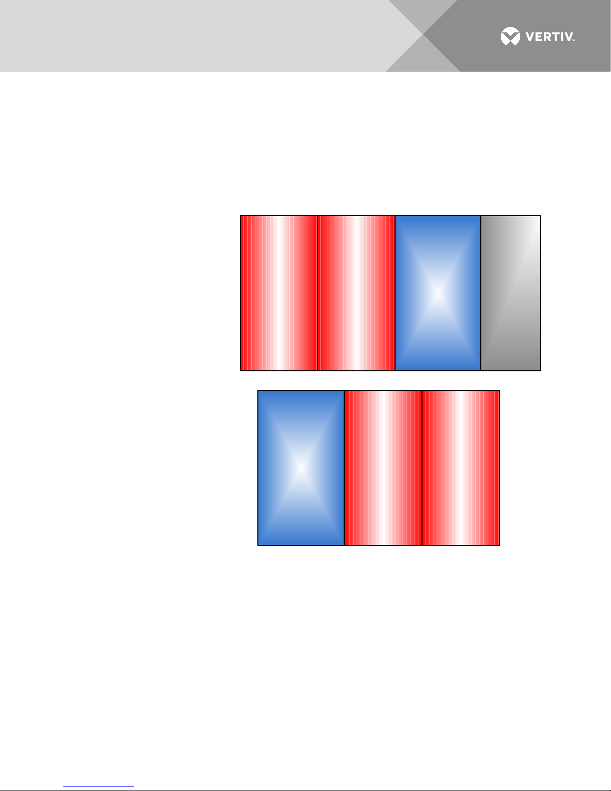
RECOMMENDED INSTALLATION
Battery cabinet systems ordered as left -side
installation will include factory -supplied
cabling to connect the battery system to the
10-120kVA UPS models . The cables will be
routed internally .
Liebert
EXM
Maintenance
Bypass
Cabinet
Optional
Liebert
EXM
UPS
Liebert
EXM
Battery
Cabinet
Additional
Liebert
EXM
Battery
Cabinet
ALTERNATE INSTALLATION
Without attached Maintenance Bypass Cabinet
Battery cabinets may be mounted to the right of
the UPS, but all cabling between the battery
cabinets and the 10-120kVA UPS models must
be external and performed by others .
Depending on the site layout, the battery cabinets can be installed in any of several ways:
• Connected—Multiple battery cabinets bolted together
• Stand-Alone System—Cabinets not bolted to a Liebert EXM
• Attached—Battery cabinets are bolted to a Liebert EXM
• Detached—Battery cabinets are not bolted to a Liebert EXM
See Figure 1.
Figure 1 Battery cabinets connected, attached to UPS
Vertiv | Liebert® EXM™ Battery Cabinet User Manual | 9
1.6.1 Connecting the Liebert EXM Battery Cabinet to the UPS
After the battery cabinet equipment has been positioned and secured for operation and the
batteries have been connected, connect the power cables as described below (see Figure 9).
1. Verify that all incoming high and low voltage power circuits are de-energized and locked out or tagged
out before installing cables or making any electrical connections.
2. Remove the UPS front input output panel to gain access to the ground and battery busbars.
3. Remove the battery cabinet front panel to gain access to the busbars.
4. Connect the safety ground and any necessary bonding ground cables to the copper ground busbar.
(example: UPS located behind the output busbars.).
All cabinets in the UPS system must be connected to the user's ground connection.
NOTE
The grounding and neutral bonding arrangement must be in accordance with the National
Electrical Code and all applicable local codes.
5. Connect the system battery cables from the UPS battery terminals (+, N, -) to battery cabinet breaker
BCB (+, N, -) as shown in Figure 9. Be sure that the battery connections are made with the right polarity,
and tighten the connections to the torque specified in Ta bl e 1 9. Do not close the battery circuit breaker
before the equipment has been commissioned.
6. Connect TB1 from battery cabinet to J22 on the UPS according to Tab le 1.
NOTE
The shunt trip drive capability for the battery breaker is 220VDC at 2.4A.
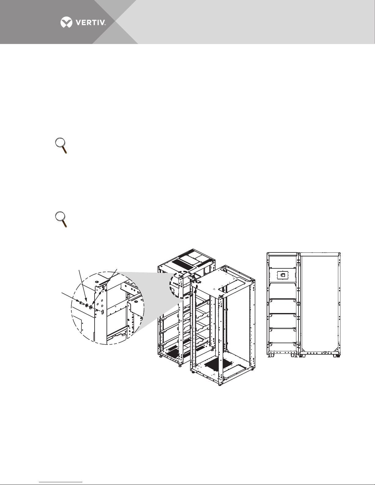
Figure 2 Bolting the Liebert EXM Battery Cabinet to the Liebert EXM UPS
Washer
2
Split, M10
Flat Washer
M10
3
B
1
Hex Head
Bolt
M10 x 30mm
DETAIL B
Liebert EXM
Battery
Cabinet
Liebert EXM
UPS
Vertiv | Liebert® EXM™ Battery Cabinet User Manual | 10
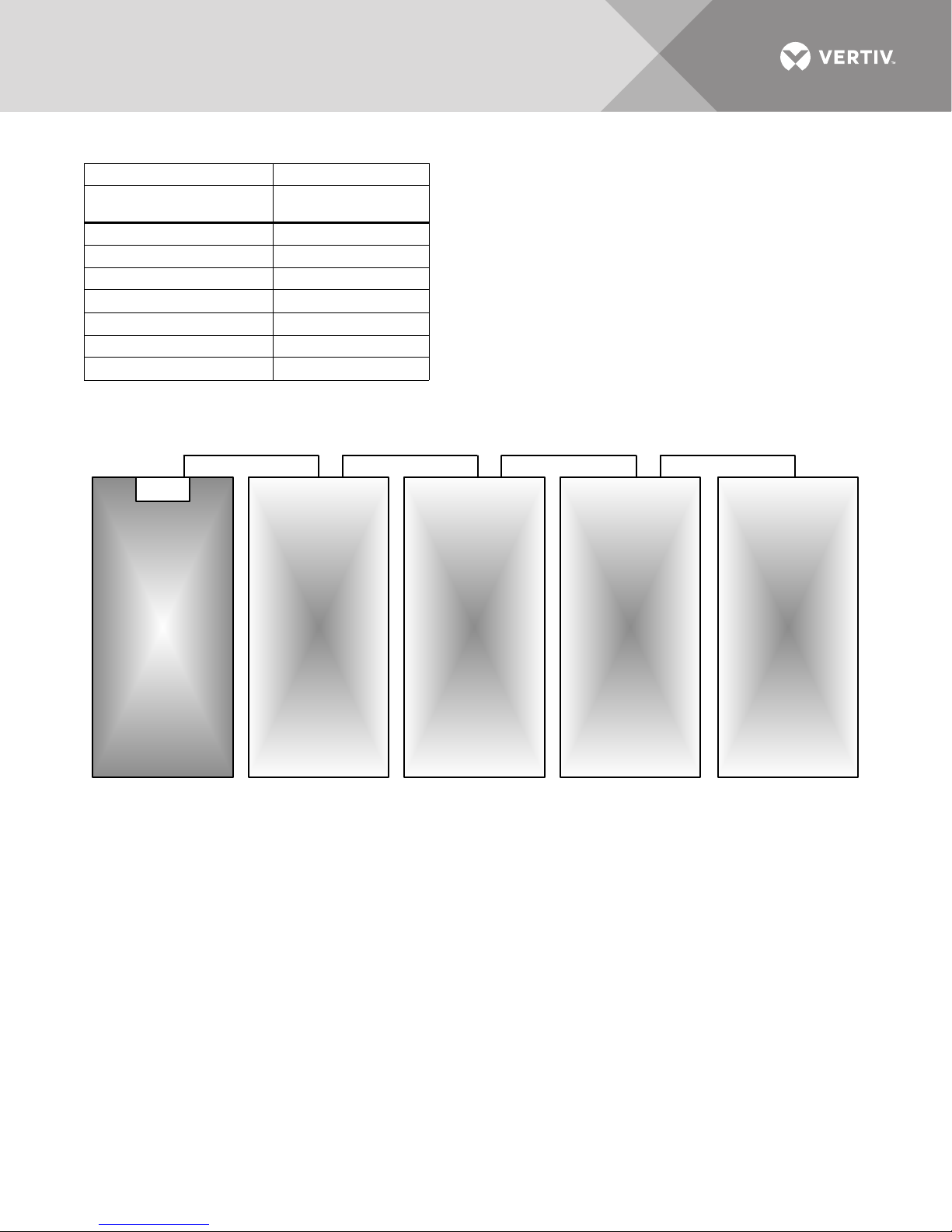
Table 1 Control wiring for Liebert EXM to battery cabinet
140-200kVA
Liebert EXM
Battery
Cabinet 1
Battery
Cabinet 2
Battery
Cabinet 3
Battery
Cabinet 4
DC Input Busbar
See Table 13 for power cable sizing.
From To
Liebert EXM UPS Bypass
Module (J22)
J22.15 TB1-12
J22.13 TB1-11
J22.11 TB1-10
J22.1 TB1-6
J22.3 TB1-7
J22.5 TB1-8
J22.7 TB1-9
Battery Cabinet
Terminal Strip (TB1)
Figure 3 Power cabling for 140-200kVA UPS
Vertiv | Liebert® EXM™ Battery Cabinet User Manual | 11

2.0 BATTERY INSTALLATION
2.1 Safety
Special care should be taken when working with the batteries associated with the Liebert EXM
Battery System equipment. When all the cells are connected together, the battery terminal
voltage will exceed 288VDC and is potentially lethal. A primary safety consideration is to install
the battery equipment in an isolated area, accessible only to properly trained and qualified
maintenance personnel.
WARNING
Risk of electrical shock and fire. Can cause equipment damage, personal injury or death.
Servicing of batteries should be performed or supervised by personnel knowledgeable of
batteries and the required precautions. Keep unauthorized personnel away from batteries.
AVERTISSEMENT
Risque de décharge électrique et d’incendie. Pouvant entraîner des dommages matériels,
des blessures et même la mort.
Le remplacement des batteries doit être effectué ou supervisé par des membres du
personnel dotés des compétences requises et connaissant les précautions à prendre. Le
personnel non autorisé ne doit pas avoir accès aux batteries.
Lead-acid batteries can present a risk of fire because they generate hydrogen gas. In addition, the
electrical connections must be protected against accidental short circuits which can cause
sparks. The following procedures should be followed:
• DO NOT SMOKE when near batteries.
• DO NOT cause flame or spark in battery area.
• Discharge static electricity from body before touching batteries by first touching a grounded metal
surface.
• After replacing battery jars in a battery cabinet, replace the retaining straps that hold the jars in place on
the shelves. This will limit accidental movement of the jars and connectors should the cabinet ever need
to be repositioned or relocated.
Regular maintenance of the battery module is an absolute necessity. Periodic inspections of
battery and terminal voltages, specific gravity and connection resistance should be made. Strictly
follow the procedures outlined in the battery manufacturer’s manual, available on the
manufacturer’s Web site.
Valve-regulated lead-acid (sealed-cell) batteries do require periodic maintenance. Although
maintenance of electrolyte levels is not required, visual inspections and checks of battery voltage
and connection resistance should be made.
NOTICE
Risk of equipment damage. Batteries should be cleaned with a dry cloth or a cloth lightly moistened with
water. Do not use cleaners on the batteries. Solvents can make the battery cases brittle.
Vertiv | Liebert® EXM™ Battery Cabinet User Manual | 12
 Loading...