

Vertiv Liebert EXM User Manual

Liebert® EXM
™
User Manual—10-40kVA, 50/60Hz UPS

©2016 Vertiv Co. All rights reserved throughout the world.
This document may contain confidential and/or proprietary information of Liebert Corporation, and its receipt or possession
does not convey any right to reproduce, disclose its contents, or to manufacture or sell anything that it may describe.
Reproduction, disclosure, or use without specific authorization from Liebert Corporation is strictly prohibited.

TABLE OF CONTENTS
IMPORTANT SAFETY INSTRUCTIONS . . . . . . . . . . . . . . . . . . . . . . . . . . . . . . . . . . . . . . . . . . . . . . . . . . . . . . .1
SAVE THESE INSTRUCTIONS . . . . . . . . . . . . . . . . . . . . . . . . . . . . . . . . . . . . . . . . . . . . . . . . . . . . . . . .1
LOSSARY OF SYMBOLS . . . . . . . . . . . . . . . . . . . . . . . . . . . . . . . . . . . . . . . . . . . . . . . . . . . . . . . . . . . . . . . 7
G
1.0 I
NTRODUCTION. . . . . . . . . . . . . . . . . . . . . . . . . . . . . . . . . . . . . . . . . . . . . . . . . . . . . . . . . . . . . . . . . 8
1.1 Operator Control and Display Panel. . . . . . . . . . . . . . . . . . . . . . . . . . . . . . . . . . . . . . . . . . . . . . . . . . . . . . . . . . . . . . . .8
2.0 INSTALLATION . . . . . . . . . . . . . . . . . . . . . . . . . . . . . . . . . . . . . . . . . . . . . . . . . . . . . . . . . . . . . . . . . 9
2.1 Initial Inspections . . . . . . . . . . . . . . . . . . . . . . . . . . . . . . . . . . . . . . . . . . . . . . . . . . . . . . . . . . . . . . . . . . . . . . . . . . . . . . . . 9
2.1.1 Storing the UPS and Batteries for Delayed Installation. . . . . . . . . . . . . . . . . . . . . . . . . . . . . . . . . . . . . . . . . . . . . . 9
2.2 Preliminary Checks . . . . . . . . . . . . . . . . . . . . . . . . . . . . . . . . . . . . . . . . . . . . . . . . . . . . . . . . . . . . . . . . . . . . . . . . . . . . . . 9
2.2.1 Identification . . . . . . . . . . . . . . . . . . . . . . . . . . . . . . . . . . . . . . . . . . . . . . . . . . . . . . . . . . . . . . . . . . . . . . . . . . . . . . . . . . . . . 9
2.3 UPS Location . . . . . . . . . . . . . . . . . . . . . . . . . . . . . . . . . . . . . . . . . . . . . . . . . . . . . . . . . . . . . . . . . . . . . . . . . . . . . . . . . . . .10
2.3.1 Positioning the UPS . . . . . . . . . . . . . . . . . . . . . . . . . . . . . . . . . . . . . . . . . . . . . . . . . . . . . . . . . . . . . . . . . . . . . . . . . . . . . . 10
2.3.2 Environmental Considerations. . . . . . . . . . . . . . . . . . . . . . . . . . . . . . . . . . . . . . . . . . . . . . . . . . . . . . . . . . . . . . . . . . . . 10
2.4 Battery Location . . . . . . . . . . . . . . . . . . . . . . . . . . . . . . . . . . . . . . . . . . . . . . . . . . . . . . . . . . . . . . . . . . . . . . . . . . . . . . . . .10
2.5 Considerations in Moving the Liebert EXM. . . . . . . . . . . . . . . . . . . . . . . . . . . . . . . . . . . . . . . . . . . . . . . . . . . . . . . .10
2.6 Mechanical Considerations . . . . . . . . . . . . . . . . . . . . . . . . . . . . . . . . . . . . . . . . . . . . . . . . . . . . . . . . . . . . . . . . . . . . . . . 11
2.6.1 Dimensions . . . . . . . . . . . . . . . . . . . . . . . . . . . . . . . . . . . . . . . . . . . . . . . . . . . . . . . . . . . . . . . . . . . . . . . . . . . . . . . . . . . . . . .12
2.6.2 Clearances . . . . . . . . . . . . . . . . . . . . . . . . . . . . . . . . . . . . . . . . . . . . . . . . . . . . . . . . . . . . . . . . . . . . . . . . . . . . . . . . . . . . . . .12
2.6.3 Floor Installation. . . . . . . . . . . . . . . . . . . . . . . . . . . . . . . . . . . . . . . . . . . . . . . . . . . . . . . . . . . . . . . . . . . . . . . . . . . . . . . . . .13
2.6.4 Cable Entry. . . . . . . . . . . . . . . . . . . . . . . . . . . . . . . . . . . . . . . . . . . . . . . . . . . . . . . . . . . . . . . . . . . . . . . . . . . . . . . . . . . . . . 14
2.7 Auxiliary Cabinets . . . . . . . . . . . . . . . . . . . . . . . . . . . . . . . . . . . . . . . . . . . . . . . . . . . . . . . . . . . . . . . . . . . . . . . . . . . . . . .14
2.8 Power Module Assembly . . . . . . . . . . . . . . . . . . . . . . . . . . . . . . . . . . . . . . . . . . . . . . . . . . . . . . . . . . . . . . . . . . . . . . . . .16
2.9 Static Bypass Assembly . . . . . . . . . . . . . . . . . . . . . . . . . . . . . . . . . . . . . . . . . . . . . . . . . . . . . . . . . . . . . . . . . . . . . . . . . . 17
3.0 ELECTRICAL CONNECTIONS—UPS. . . . . . . . . . . . . . . . . . . . . . . . . . . . . . . . . . . . . . . . . . . . . . . . .18
3.1 Power Cabling . . . . . . . . . . . . . . . . . . . . . . . . . . . . . . . . . . . . . . . . . . . . . . . . . . . . . . . . . . . . . . . . . . . . . . . . . . . . . . . . . . .18
3.1.1 Lug Size and Cable Rating . . . . . . . . . . . . . . . . . . . . . . . . . . . . . . . . . . . . . . . . . . . . . . . . . . . . . . . . . . . . . . . . . . . . . . . .18
3.2 External Protective Devices . . . . . . . . . . . . . . . . . . . . . . . . . . . . . . . . . . . . . . . . . . . . . . . . . . . . . . . . . . . . . . . . . . . . . .19
3.2.1 Rectifier and Bypass Input Supply of the UPS . . . . . . . . . . . . . . . . . . . . . . . . . . . . . . . . . . . . . . . . . . . . . . . . . . . . . .19
3.2.2 UPS Output . . . . . . . . . . . . . . . . . . . . . . . . . . . . . . . . . . . . . . . . . . . . . . . . . . . . . . . . . . . . . . . . . . . . . . . . . . . . . . . . . . . . . .19
3.2.3 UPS Input Configuration . . . . . . . . . . . . . . . . . . . . . . . . . . . . . . . . . . . . . . . . . . . . . . . . . . . . . . . . . . . . . . . . . . . . . . . . . .19
3.2.4 UPS Input Configuration with Transformers. . . . . . . . . . . . . . . . . . . . . . . . . . . . . . . . . . . . . . . . . . . . . . . . . . . . . . . 22
3.2.5 Cabling Guidelines . . . . . . . . . . . . . . . . . . . . . . . . . . . . . . . . . . . . . . . . . . . . . . . . . . . . . . . . . . . . . . . . . . . . . . . . . . . . . . . 22
3.2.6 Cable Connections. . . . . . . . . . . . . . . . . . . . . . . . . . . . . . . . . . . . . . . . . . . . . . . . . . . . . . . . . . . . . . . . . . . . . . . . . . . . . . . 23
3.2.7 Accessory Fuses and Back-Feed Breaker Wiring . . . . . . . . . . . . . . . . . . . . . . . . . . . . . . . . . . . . . . . . . . . . . . . . . . 24
3.2.8 Safety Ground . . . . . . . . . . . . . . . . . . . . . . . . . . . . . . . . . . . . . . . . . . . . . . . . . . . . . . . . . . . . . . . . . . . . . . . . . . . . . . . . . . . 26
3.2.9 Protective Devices . . . . . . . . . . . . . . . . . . . . . . . . . . . . . . . . . . . . . . . . . . . . . . . . . . . . . . . . . . . . . . . . . . . . . . . . . . . . . . . 27
3.2.10 Cabling Procedure . . . . . . . . . . . . . . . . . . . . . . . . . . . . . . . . . . . . . . . . . . . . . . . . . . . . . . . . . . . . . . . . . . . . . . . . . . . . . . . 28
3.3 Control Cables Details . . . . . . . . . . . . . . . . . . . . . . . . . . . . . . . . . . . . . . . . . . . . . . . . . . . . . . . . . . . . . . . . . . . . . . . . . . 29
3.3.1 Static Bypass Assembly Features. . . . . . . . . . . . . . . . . . . . . . . . . . . . . . . . . . . . . . . . . . . . . . . . . . . . . . . . . . . . . . . . . 29
i

3.4 Dry Contacts . . . . . . . . . . . . . . . . . . . . . . . . . . . . . . . . . . . . . . . . . . . . . . . . . . . . . . . . . . . . . . . . . . . . . . . . . . . . . . . . . . . 30
3.4.1 Input Dry Contacts. . . . . . . . . . . . . . . . . . . . . . . . . . . . . . . . . . . . . . . . . . . . . . . . . . . . . . . . . . . . . . . . . . . . . . . . . . . . . . . 30
3.4.2 Output Dry Contacts. . . . . . . . . . . . . . . . . . . . . . . . . . . . . . . . . . . . . . . . . . . . . . . . . . . . . . . . . . . . . . . . . . . . . . . . . . . . . 32
3.4.3 Liebert BDC Interface . . . . . . . . . . . . . . . . . . . . . . . . . . . . . . . . . . . . . . . . . . . . . . . . . . . . . . . . . . . . . . . . . . . . . . . . . . . . 33
3.4.4 Battery Cabinet Interface Connectors . . . . . . . . . . . . . . . . . . . . . . . . . . . . . . . . . . . . . . . . . . . . . . . . . . . . . . . . . . . . 33
3.4.5 EPO Input—Optional . . . . . . . . . . . . . . . . . . . . . . . . . . . . . . . . . . . . . . . . . . . . . . . . . . . . . . . . . . . . . . . . . . . . . . . . . . . . . 34
3.5 Parallel Cable Connections . . . . . . . . . . . . . . . . . . . . . . . . . . . . . . . . . . . . . . . . . . . . . . . . . . . . . . . . . . . . . . . . . . . . . . 35
4.0 INSTALLATION DRAWINGS . . . . . . . . . . . . . . . . . . . . . . . . . . . . . . . . . . . . . . . . . . . . . . . . . . . . . . . 36
5.0 O
PTION INSTALLATION . . . . . . . . . . . . . . . . . . . . . . . . . . . . . . . . . . . . . . . . . . . . . . . . . . . . . . . . . 39
5.1 Liebert IntelliSlot™ Communication. . . . . . . . . . . . . . . . . . . . . . . . . . . . . . . . . . . . . . . . . . . . . . . . . . . . . . . . . . . . . . . 39
5.2 Liebert IntelliSlot Web Card—SNMP/HTTP Network Interface Card . . . . . . . . . . . . . . . . . . . . . . . . . . . . . . . 39
5.2.1 Liebert IntelliSlot Unity Cards—IS-UNITY-LIFE, IS-UNITY-S, IS-UNITY-DP. . . . . . . . . . . . . . . . . . . . . . . . . . 39
5.3 Liebert IntelliSlot Web Card—Optional . . . . . . . . . . . . . . . . . . . . . . . . . . . . . . . . . . . . . . . . . . . . . . . . . . . . . . . . . . . 40
5.4 Liebert IntelliSlot™ Relay Card . . . . . . . . . . . . . . . . . . . . . . . . . . . . . . . . . . . . . . . . . . . . . . . . . . . . . . . . . . . . . . . . . . . 40
5.4.1 Liebert IntelliSlot Relay Card Pin Configuration . . . . . . . . . . . . . . . . . . . . . . . . . . . . . . . . . . . . . . . . . . . . . . . . . . . 40
5.4.2 Liebert IntelliSlot
™
Relay Card Jumper Setup . . . . . . . . . . . . . . . . . . . . . . . . . . . . . . . . . . . . . . . . . . . . . . . . . . . . . 42
6.0 OPERATION. . . . . . . . . . . . . . . . . . . . . . . . . . . . . . . . . . . . . . . . . . . . . . . . . . . . . . . . . . . . . . . . . . . 43
6.1 Liebert EXM Operating Modes. . . . . . . . . . . . . . . . . . . . . . . . . . . . . . . . . . . . . . . . . . . . . . . . . . . . . . . . . . . . . . . . . . . 43
6.2 UPS Startup . . . . . . . . . . . . . . . . . . . . . . . . . . . . . . . . . . . . . . . . . . . . . . . . . . . . . . . . . . . . . . . . . . . . . . . . . . . . . . . . . . . . 46
6.2.1 Startup Procedure . . . . . . . . . . . . . . . . . . . . . . . . . . . . . . . . . . . . . . . . . . . . . . . . . . . . . . . . . . . . . . . . . . . . . . . . . . . . . . . 46
6.2.2 Startup in Eco Mode . . . . . . . . . . . . . . . . . . . . . . . . . . . . . . . . . . . . . . . . . . . . . . . . . . . . . . . . . . . . . . . . . . . . . . . . . . . . . 46
6.2.3 Switching Between UPS Operation Modes . . . . . . . . . . . . . . . . . . . . . . . . . . . . . . . . . . . . . . . . . . . . . . . . . . . . . . . . 47
6.3 Switching the UPS from Normal Operation to Maintenance Bypass . . . . . . . . . . . . . . . . . . . . . . . . . . . . . . . 47
6.4 Switching the UPS from Maintenance Bypass to Normal Operation . . . . . . . . . . . . . . . . . . . . . . . . . . . . . . . 49
6.5 De-Energize Liebert EXM with Maintenance Bypass Cabinet . . . . . . . . . . . . . . . . . . . . . . . . . . . . . . . . . . . . . 50
6.6 De-Energize Liebert EXM Without Maintenance Bypass Cabinet . . . . . . . . . . . . . . . . . . . . . . . . . . . . . . . . . . 50
6.7 Parallel Operations—Determine Control Panel Firmware Version. . . . . . . . . . . . . . . . . . . . . . . . . . . . . . . . . . 52
6.8 Parallel Operations—Software Version 1.1 . . . . . . . . . . . . . . . . . . . . . . . . . . . . . . . . . . . . . . . . . . . . . . . . . . . . . . . . 52
6.8.1 De-Energize a Liebert EXM Parallel System—Software Version 1.1. . . . . . . . . . . . . . . . . . . . . . . . . . . . . . . . . . 52
6.8.2 Re-Energize a Liebert EXM Parallel System—Software Version 1.1. . . . . . . . . . . . . . . . . . . . . . . . . . . . . . . . . . 52
6.9 Parallel Operations—Software Version 1.0. . . . . . . . . . . . . . . . . . . . . . . . . . . . . . . . . . . . . . . . . . . . . . . . . . . . . . . . 53
6.9.1 De-Energize a Liebert EXM Parallel System—Software Version 1.0 . . . . . . . . . . . . . . . . . . . . . . . . . . . . . . . . . 53
6.9.2 Re-Energize a Liebert EXM Parallel System—Software Version 1.0 . . . . . . . . . . . . . . . . . . . . . . . . . . . . . . . . . 53
6.9.3 De-Energize and Isolate a Single Liebert EXM in a Parallel System—Software Version 1.0 . . . . . . . . . . . 54
6.9.4 Re-Energize a Single Liebert EXM in a Parallel System—Software Version 1.0 . . . . . . . . . . . . . . . . . . . . . . 54
6.9.5 Place a Liebert EXM Parallel System with SKRU Interlock in Maintenance Bypass—Software
Version 1.0. . . . . . . . . . . . . . . . . . . . . . . . . . . . . . . . . . . . . . . . . . . . . . . . . . . . . . . . . . . . . . . . . . . . . . . . . . . . . . . . . . . . . . . 55
6.9.6 Re-Energize a Liebert EXM Parallel System with SKRU Interlock Online from Maintenance
Bypass—Software Version 1.0 . . . . . . . . . . . . . . . . . . . . . . . . . . . . . . . . . . . . . . . . . . . . . . . . . . . . . . . . . . . . . . . . . . . . 56
6.10 Emergency Shutdown With EPO . . . . . . . . . . . . . . . . . . . . . . . . . . . . . . . . . . . . . . . . . . . . . . . . . . . . . . . . . . . . . . . . . 56
6.11 Auto Restart . . . . . . . . . . . . . . . . . . . . . . . . . . . . . . . . . . . . . . . . . . . . . . . . . . . . . . . . . . . . . . . . . . . . . . . . . . . . . . . . . . . . 56
6.12 Reset After Shutdown for Emergency Stop (EPO Action) or Other Conditions . . . . . . . . . . . . . . . . . . . . . 57
6.13 Battery Protection . . . . . . . . . . . . . . . . . . . . . . . . . . . . . . . . . . . . . . . . . . . . . . . . . . . . . . . . . . . . . . . . . . . . . . . . . . . . . . 57
6.13.1 Battery Undervoltage Warning . . . . . . . . . . . . . . . . . . . . . . . . . . . . . . . . . . . . . . . . . . . . . . . . . . . . . . . . . . . . . . . . . . . 57
6.13.2 Battery End-of-Discharge (EOD) Protection. . . . . . . . . . . . . . . . . . . . . . . . . . . . . . . . . . . . . . . . . . . . . . . . . . . . . . . 57
ii

6.14 Operation. . . . . . . . . . . . . . . . . . . . . . . . . . . . . . . . . . . . . . . . . . . . . . . . . . . . . . . . . . . . . . . . . . . . . . . . . . . . . . . . . . . . . . . 58
6.15 Static Bypass Switch . . . . . . . . . . . . . . . . . . . . . . . . . . . . . . . . . . . . . . . . . . . . . . . . . . . . . . . . . . . . . . . . . . . . . . . . . . . . 58
7.0 SPECIFICATIONS AND TECHNICAL DATA. . . . . . . . . . . . . . . . . . . . . . . . . . . . . . . . . . . . . . . . . . . . 59
7.1 Conformity and Standards . . . . . . . . . . . . . . . . . . . . . . . . . . . . . . . . . . . . . . . . . . . . . . . . . . . . . . . . . . . . . . . . . . . . . . 59
7.1.1 ENERGY STAR® Certification . . . . . . . . . . . . . . . . . . . . . . . . . . . . . . . . . . . . . . . . . . . . . . . . . . . . . . . . . . . . . . . . . . . . . 59
7.2 UPS Environmental . . . . . . . . . . . . . . . . . . . . . . . . . . . . . . . . . . . . . . . . . . . . . . . . . . . . . . . . . . . . . . . . . . . . . . . . . . . . . 59
7.3 UPS Electrical Characteristics . . . . . . . . . . . . . . . . . . . . . . . . . . . . . . . . . . . . . . . . . . . . . . . . . . . . . . . . . . . . . . . . . . . 60
8.0 MAINTENANCE . . . . . . . . . . . . . . . . . . . . . . . . . . . . . . . . . . . . . . . . . . . . . . . . . . . . . . . . . . . . . . . . 64
8.1 Safety Precautions . . . . . . . . . . . . . . . . . . . . . . . . . . . . . . . . . . . . . . . . . . . . . . . . . . . . . . . . . . . . . . . . . . . . . . . . . . . . . . 64
8.2 Battery Maintenance . . . . . . . . . . . . . . . . . . . . . . . . . . . . . . . . . . . . . . . . . . . . . . . . . . . . . . . . . . . . . . . . . . . . . . . . . . . . 66
8.3 Battery Safety Precautions . . . . . . . . . . . . . . . . . . . . . . . . . . . . . . . . . . . . . . . . . . . . . . . . . . . . . . . . . . . . . . . . . . . . . . 67
8.4 Limited-Life Components . . . . . . . . . . . . . . . . . . . . . . . . . . . . . . . . . . . . . . . . . . . . . . . . . . . . . . . . . . . . . . . . . . . . . . . 69
8.5 Routine Maintenance . . . . . . . . . . . . . . . . . . . . . . . . . . . . . . . . . . . . . . . . . . . . . . . . . . . . . . . . . . . . . . . . . . . . . . . . . . . 69
8.5.1 Record Log . . . . . . . . . . . . . . . . . . . . . . . . . . . . . . . . . . . . . . . . . . . . . . . . . . . . . . . . . . . . . . . . . . . . . . . . . . . . . . . . . . . . . . 70
8.5.2 Air Filters. . . . . . . . . . . . . . . . . . . . . . . . . . . . . . . . . . . . . . . . . . . . . . . . . . . . . . . . . . . . . . . . . . . . . . . . . . . . . . . . . . . . . . . . 70
8.5.3 Torque Requirements . . . . . . . . . . . . . . . . . . . . . . . . . . . . . . . . . . . . . . . . . . . . . . . . . . . . . . . . . . . . . . . . . . . . . . . . . . . . .71
8.6 Detecting Trouble. . . . . . . . . . . . . . . . . . . . . . . . . . . . . . . . . . . . . . . . . . . . . . . . . . . . . . . . . . . . . . . . . . . . . . . . . . . . . . . 72
8.7 Reporting a Problem . . . . . . . . . . . . . . . . . . . . . . . . . . . . . . . . . . . . . . . . . . . . . . . . . . . . . . . . . . . . . . . . . . . . . . . . . . . . 72
8.8 Corrective Actions . . . . . . . . . . . . . . . . . . . . . . . . . . . . . . . . . . . . . . . . . . . . . . . . . . . . . . . . . . . . . . . . . . . . . . . . . . . . . . 72
8.9 Recommended Test Equipment. . . . . . . . . . . . . . . . . . . . . . . . . . . . . . . . . . . . . . . . . . . . . . . . . . . . . . . . . . . . . . . . . . 72
APPENDIX A-HAZARDOUS SUBSTANCES OR ELEMENTS ANNOUNCEMENT . . . . . . . . . . . . . . . . . . . . A73
PPENDIX B-UPS STATU S MESSAGES. . . . . . . . . . . . . . . . . . . . . . . . . . . . . . . . . . . . . . . . . . . . . . . . . A74
A
iii

FIGURES
Figure 1 UPS dimensions. . . . . . . . . . . . . . . . . . . . . . . . . . . . . . . . . . . . . . . . . . . . . . . . . . . . . . . . . . . . . . . . . . . . . . . . . . . . . . 12
Figure 2 Clearances—Front, side and rear . . . . . . . . . . . . . . . . . . . . . . . . . . . . . . . . . . . . . . . . . . . . . . . . . . . . . . . . . . . . .13
Figure 3 Cable entry locations. . . . . . . . . . . . . . . . . . . . . . . . . . . . . . . . . . . . . . . . . . . . . . . . . . . . . . . . . . . . . . . . . . . . . . . . .14
Figure 4 Cabinet arrangement. . . . . . . . . . . . . . . . . . . . . . . . . . . . . . . . . . . . . . . . . . . . . . . . . . . . . . . . . . . . . . . . . . . . . . . . . 15
Figure 5 Power Module Assembly indicators and controls . . . . . . . . . . . . . . . . . . . . . . . . . . . . . . . . . . . . . . . . . . . . . .16
Figure 6 Static Bypass Assembly connections . . . . . . . . . . . . . . . . . . . . . . . . . . . . . . . . . . . . . . . . . . . . . . . . . . . . . . . . .17
Figure 7 Single UPS block diagram—Dual input, single source configuration, without bypass cabinet . . . 20
Figure 8 Single UPS block diagram—Dual input, single source configuration . . . . . . . . . . . . . . . . . . . . . . . . . . . .21
Figure 9 Liebert EXM in a split bypass configuration . . . . . . . . . . . . . . . . . . . . . . . . . . . . . . . . . . . . . . . . . . . . . . . . . . 22
Figure 10 Input busbars—Liebert EXM 10-40kVA frame . . . . . . . . . . . . . . . . . . . . . . . . . . . . . . . . . . . . . . . . . . . . . . . . 23
Figure 11 Accessory fuses . . . . . . . . . . . . . . . . . . . . . . . . . . . . . . . . . . . . . . . . . . . . . . . . . . . . . . . . . . . . . . . . . . . . . . . . . . . . 24
Figure 12 Dual input back-feed breaker wiring when bypass distribution cabinet not used . . . . . . . . . . . . . . . 25
Figure 13 Ground and neutral busbar connections—10-40kVA frame busbars . . . . . . . . . . . . . . . . . . . . . . . . . . . 27
Figure 14 Static bypass assembly connections to display cabinet and options. . . . . . . . . . . . . . . . . . . . . . . . . . . 29
Figure 15 Auxiliary terminal block detail (static switch assembly front panel). . . . . . . . . . . . . . . . . . . . . . . . . . . . 29
Figure 16 Input dry contacts . . . . . . . . . . . . . . . . . . . . . . . . . . . . . . . . . . . . . . . . . . . . . . . . . . . . . . . . . . . . . . . . . . . . . . . . . . 30
Figure 17 Output dry contacts and EPO wiring . . . . . . . . . . . . . . . . . . . . . . . . . . . . . . . . . . . . . . . . . . . . . . . . . . . . . . . . . 32
Figure 18 Battery cabinet interface—J22 . . . . . . . . . . . . . . . . . . . . . . . . . . . . . . . . . . . . . . . . . . . . . . . . . . . . . . . . . . . . . . 33
Figure 19 EPO wiring and signal names for J2 . . . . . . . . . . . . . . . . . . . . . . . . . . . . . . . . . . . . . . . . . . . . . . . . . . . . . . . . . . 34
Figure 20 Single UPS Remote Emergency Power Off. . . . . . . . . . . . . . . . . . . . . . . . . . . . . . . . . . . . . . . . . . . . . . . . . . . . 35
Figure 21 Parallel cable wiring diagram . . . . . . . . . . . . . . . . . . . . . . . . . . . . . . . . . . . . . . . . . . . . . . . . . . . . . . . . . . . . . . . . 35
Figure 22 UPS dimensions—Front view . . . . . . . . . . . . . . . . . . . . . . . . . . . . . . . . . . . . . . . . . . . . . . . . . . . . . . . . . . . . . . . . 36
Figure 23 UPS main components—Typical 10-40kVA unit . . . . . . . . . . . . . . . . . . . . . . . . . . . . . . . . . . . . . . . . . . . . . . 37
Figure 24 UPS cable connections—10-40kVA frames. . . . . . . . . . . . . . . . . . . . . . . . . . . . . . . . . . . . . . . . . . . . . . . . . . . 38
Figure 25 Liebert IntelliSlot Web card display . . . . . . . . . . . . . . . . . . . . . . . . . . . . . . . . . . . . . . . . . . . . . . . . . . . . . . . . . . 40
Figure 26 Pin location and numbering. . . . . . . . . . . . . . . . . . . . . . . . . . . . . . . . . . . . . . . . . . . . . . . . . . . . . . . . . . . . . . . . . . .41
Figure 27 Jumper location and numbering . . . . . . . . . . . . . . . . . . . . . . . . . . . . . . . . . . . . . . . . . . . . . . . . . . . . . . . . . . . . . 42
Figure 28 One-line diagram, single-input UPS with 3-breaker maintenance bypass cabinet and
panelboard . . . . . . . . . . . . . . . . . . . . . . . . . . . . . . . . . . . . . . . . . . . . . . . . . . . . . . . . . . . . . . . . . . . . . . . . . . . . . . . . . 48
Figure 29 Typical configuration for single UPS . . . . . . . . . . . . . . . . . . . . . . . . . . . . . . . . . . . . . . . . . . . . . . . . . . . . . . . . . .51
Figure 30 Air filter replacement. . . . . . . . . . . . . . . . . . . . . . . . . . . . . . . . . . . . . . . . . . . . . . . . . . . . . . . . . . . . . . . . . . . . . . . . . 71
iv

TABLES
Table 1 Weights for Liebert EXM 10-40kVA frame . . . . . . . . . . . . . . . . . . . . . . . . . . . . . . . . . . . . . . . . . . . . . . . . . . . . . 12
Table 2 LED indications on power module assembly. . . . . . . . . . . . . . . . . . . . . . . . . . . . . . . . . . . . . . . . . . . . . . . . . . .16
Table 3 Busbars (for power wiring) . . . . . . . . . . . . . . . . . . . . . . . . . . . . . . . . . . . . . . . . . . . . . . . . . . . . . . . . . . . . . . . . . . .18
Table 4 Terminal block with compression lugs (for control wiring) . . . . . . . . . . . . . . . . . . . . . . . . . . . . . . . . . . . . . 18
Table 5 Input dry contacts—J26. . . . . . . . . . . . . . . . . . . . . . . . . . . . . . . . . . . . . . . . . . . . . . . . . . . . . . . . . . . . . . . . . . . . . . 31
Table 6 Output dry contact relays . . . . . . . . . . . . . . . . . . . . . . . . . . . . . . . . . . . . . . . . . . . . . . . . . . . . . . . . . . . . . . . . . . . 32
Table 7 Liebert BDC interface . . . . . . . . . . . . . . . . . . . . . . . . . . . . . . . . . . . . . . . . . . . . . . . . . . . . . . . . . . . . . . . . . . . . . . . 33
Table 8 Battery cabinet interface—J22 . . . . . . . . . . . . . . . . . . . . . . . . . . . . . . . . . . . . . . . . . . . . . . . . . . . . . . . . . . . . . . 33
Table 9 EPO input contact relays—J2. . . . . . . . . . . . . . . . . . . . . . . . . . . . . . . . . . . . . . . . . . . . . . . . . . . . . . . . . . . . . . . . 34
Table 10 Liebert EXM communication options. . . . . . . . . . . . . . . . . . . . . . . . . . . . . . . . . . . . . . . . . . . . . . . . . . . . . . . . . 39
Table 11 Relay card pin configuration . . . . . . . . . . . . . . . . . . . . . . . . . . . . . . . . . . . . . . . . . . . . . . . . . . . . . . . . . . . . . . . . . .41
Table 12 Jumper connections . . . . . . . . . . . . . . . . . . . . . . . . . . . . . . . . . . . . . . . . . . . . . . . . . . . . . . . . . . . . . . . . . . . . . . . . 42
Table 13 UPS operating modes . . . . . . . . . . . . . . . . . . . . . . . . . . . . . . . . . . . . . . . . . . . . . . . . . . . . . . . . . . . . . . . . . . . . . . . 58
Table 14 Environmental requirements. . . . . . . . . . . . . . . . . . . . . . . . . . . . . . . . . . . . . . . . . . . . . . . . . . . . . . . . . . . . . . . . . 59
Table 15 UPS mechanical characteristics. . . . . . . . . . . . . . . . . . . . . . . . . . . . . . . . . . . . . . . . . . . . . . . . . . . . . . . . . . . . . . 59
Table 16 UPS currents and terminals—Input (for single-input unit, 208V operation) . . . . . . . . . . . . . . . . . . . . 60
Table 17 UPS currents and terminals—Input (for dual-input unit only, 208V operation) . . . . . . . . . . . . . . . . . 60
Table 18 UPS currents and terminals—Bypass input (for dual-input units, 208V operation) . . . . . . . . . . . . . 60
Table 19 UPS currents and terminals—Output 208V. . . . . . . . . . . . . . . . . . . . . . . . . . . . . . . . . . . . . . . . . . . . . . . . . . . 60
Table 20 AC/AC efficiency, loss and air exchange. . . . . . . . . . . . . . . . . . . . . . . . . . . . . . . . . . . . . . . . . . . . . . . . . . . . . . .61
Table 21 Rectifier input. . . . . . . . . . . . . . . . . . . . . . . . . . . . . . . . . . . . . . . . . . . . . . . . . . . . . . . . . . . . . . . . . . . . . . . . . . . . . . . .61
Table 22 Recommended lug sizes (compression type) M10, 3/8" bolt . . . . . . . . . . . . . . . . . . . . . . . . . . . . . . . . . . . .61
Table 23 Battery cabinet system—UPS and battery cabinet. . . . . . . . . . . . . . . . . . . . . . . . . . . . . . . . . . . . . . . . . . . . .61
Table 24 Inverter output to critical load . . . . . . . . . . . . . . . . . . . . . . . . . . . . . . . . . . . . . . . . . . . . . . . . . . . . . . . . . . . . . . . 62
Table 25 Battery DC intermediate circuit . . . . . . . . . . . . . . . . . . . . . . . . . . . . . . . . . . . . . . . . . . . . . . . . . . . . . . . . . . . . . . 62
Table 26 Bypass input . . . . . . . . . . . . . . . . . . . . . . . . . . . . . . . . . . . . . . . . . . . . . . . . . . . . . . . . . . . . . . . . . . . . . . . . . . . . . . . . 63
Table 27 Component service life . . . . . . . . . . . . . . . . . . . . . . . . . . . . . . . . . . . . . . . . . . . . . . . . . . . . . . . . . . . . . . . . . . . . . . 69
Table 28 Busbars (for power wiring) . . . . . . . . . . . . . . . . . . . . . . . . . . . . . . . . . . . . . . . . . . . . . . . . . . . . . . . . . . . . . . . . . . . 71
Table 29 Terminal block with compression lugs (for control wiring) . . . . . . . . . . . . . . . . . . . . . . . . . . . . . . . . . . . . .71
Table 30 Recommended test equipment and tools. . . . . . . . . . . . . . . . . . . . . . . . . . . . . . . . . . . . . . . . . . . . . . . . . . . . . 72
Table 31 Hazardous substances or elements . . . . . . . . . . . . . . . . . . . . . . . . . . . . . . . . . . . . . . . . . . . . . . . . . . . . . . . . . . 73
Table 32 UPS status messages . . . . . . . . . . . . . . . . . . . . . . . . . . . . . . . . . . . . . . . . . . . . . . . . . . . . . . . . . . . . . . . . . . . . . . . 74
v

vi

Important Safety Instructions
!
!
!
IMPORTANT SAFETY INSTRUCTIONS
SAVE THESE INSTRUCTIONS
This manual contains important instructions that should be followed during installation of the Liebert EXM.
Read this manual thoroughly, paying special attention to the sections that apply to your installation, before
working with the UPS. Retain this manual for use by installing personnel.
A properly trained and qualified electrical contractor should oversee the installation of the equipment.
The Liebert EXM cannot be put into operation until it is commissioned by the manufacturer or authorized
engineer. Otherwise, human safety may be endangered and damage to the UPS will not be covered by the
warranty.
The Liebert EXM is designed for commercial and industrial uses and cannot be used as life support equipment.
WARNING
Internal battery strapping must be verified prior to moving a battery cabinet (after initial installation).
• Battery cabinets contain non-spillable batteries.
• Keep units upright.
•Do not stack.
• Do not tilt.
Failure to heed this warning could result in smoke, fire or electric hazard.
Call 1-800-LIEBERT prior to moving battery cabinets (after initial installation).
AVERTISSEMENT
L’arrimage des batteries internes doit être vérifié avant de déplacer une armoire de batteries (après
l’installation initiale).
• Les armoires de batteries contiennent des batteries étanches.
• Maintenir les systèmes à la verticale.
• Ne pas empiler.
• Ne pas incliner.
Le non-respect de ces consignes comporte des risques liés à la fumée, au feu ou à l’électricité.
Composez le 1 800 LIEBERT avant de déplacer des armoires de batteries (après l’installation initiale).
WARNING
Risk of electrical shock and fire. Can cause equipment damage, personal injury or death.
Lead-acid batteries contain hazardous materials. Batteries must be handled, transported and recycled or
discarded in accordance with federal, state and local regulations. Because lead is a toxic substance, leadacid batteries must be recycled rather than discarded.
Do not dispose of battery or batteries in a fire. The battery may explode.
Do not open or mutilate the battery or batteries. Released electrolyte is harmful to the skin and eyes. It is
toxic.
The following precautions must be observed when working on batteries:
• Remove watches, rings and other metal objects.
• Use tools with insulated handles.
• Wear rubber gloves and boots.
• Do not lay tools or metal parts on top of batteries.
• Disconnect charging source prior to connecting or disconnecting battery terminals.
• Determine whether the battery is grounded. If it is grounded, remove source of ground.
Contact with any part of a grounded battery can result in electrical shock. The likelihood of such shock
will be reduced if such grounds are removed during installation and maintenance.
Vertiv |Liebert
®
EXM™ 10-40kVA, 50/60Hz User Manual 1

Important Safety Instructions
!
!
AVERTISSEMENT
Risque de décharge électrique et d’incendie. pouvant entraîner des dommages matériels, des blessures
et même la mort.
Les batteries au plomb-acide renferment des matières dangereuses. Les batteries doivent être
manipulées, transportées, recyclées ou jetées conformément aux règlements fédéraux, provinciaux et
municipaux. Étant donné que le plomb est une substance toxique, les batteries au plomb-acide doivent
être recyclées plutôt que mises au rebut.
Ne jetez jamais de batteries au feu car elles risquent d’exploser.
Vous ne devez ni ouvrir ni percer les batteries, car l’électrolyte qui s'en écoulerait est nocif pour la peau et
les yeux. Cet électrolyte est toxique.
Lorsque vous travaillez avec des batteries, prenez les précautions suivantes :
• Retirez montre, bagues et tout autre objet métallique.
• Utilisez des outils dont le manche est isolé.
• Portez des gants et des bottes de caoutchouc.
• Ne posez aucun outil ni pièce métallique sur le dessus d’une batterie.
• Déconnectez la source de chargement avant de brancher ou de débrancher les bornes d’une
batterie.
• Vérifiez si la batterie est mise à la terre. Le cas échéant, éliminez la cause de la mise à la terre.
Le contact avec toute partie d'une batterie mise à la terre peut provoquer une décharge électrique. Pour
réduire de tels risques d'accident, débranchez les prises de terre avant de procéder à l’installation ou à
l'entretien.
WARNING
Risk of electrical shock. Can cause personal injury or death.
This UPS has several circuits that are energized with high DC as well as AC voltages. Check for voltage
with both AC and DC voltmeters before working within the UPS. Check for voltage with both AC and DC
voltmeters before making contact.
Only properly trained and qualified personnel wearing appropriate safety headgear, gloves, shoes and
glasses should be involved in installing the UPS or preparing the UPS for installation. When performing
maintenance with any part of the equipment under power, service personnel and test equipment should
be standing on rubber mats.
In case of fire involving electrical equipment, use only carbon dioxide fire extinguishers or those approved
for use in fighting electrical fires.
Extreme caution is required when performing installation and maintenance.
Special safety precautions are required for procedures involving handling, installation and maintenance of
the UPS system. Observe all safety precautions in this manual before handling or installing the UPS
system. Observe all precautions before as well as during performance of all maintenance procedures.
Observe all DC safety precautions before working on or near the DC system.
Vertiv | Liebert
®
EXM™ 10-40kVA, 50/60Hz User Manual 2
Important Safety Instructions
!
!
!
AVERTISSEMENT
Risque de décharge électrique pouvant causer des blessures graves, voire mortelles.
Ce système ASC comporte plusieurs circuits à haute tension c.a et c.c. Vérifiez les tensions au moyen de
voltmètres c.a. et c.c. avant d’utiliser le système ASC. Vérifiez les tensions avec des voltmètres c.a. et c.c.
avant d’établir tout contact.
Seuls des employés qualifiés et dûment formés portant un casque, des gants, des chaussures et des
lunettes de sécurité adéquats doivent se charger d’installer le système ASC ou de le préparer pour
l’installation.Les responsables de l’entretien et l’équipement d’essai doivent reposer sur des tapis de
caoutchouc lors de toute intervention sur une pièce d’équipement sous tension.
En cas d’incendie associé à du matériel électrique, n’utilisez que des extincteurs à dioxyde de carbone ou
homologués pour la lutte contre les incendies d’origine électrique.
Les opérations d’installation et d’entretien requièrent une extrême prudence.
Des précautions de sécurité spéciales sont requises pour les procédures associées à la manutention, à
l’installation et à l’entretien du système ASC. Observez toutes les précautions de sécurité décrites dans le
présent manuel avant de manipuler ou d’installer le système ASC. Observez également toutes les
précautions avant et pendant toutes les procédures d’entretien. Observez toutes les précautions de
sécurité appropriées lorsque vous travaillez sur à proximité d’une source c.c. de sécurité appropriées dès
que vous vous trouvez à proximité d’une source c.c.
WARNING
Risk of heavy unit falling over. Improper handling can cause equipment damage, injury or death.
Exercise extreme care when handling UPS cabinets to avoid equipment damage or injury to personnel.
The UPS module weight is up to 956 lb. (434kg).
Locate center of gravity symbols and determine unit weight before handling each cabinet. Test lift
and balance the cabinets before transporting. Maintain minimum tilt from vertical at all times.
Slots at the base of the module cabinets are intended for forklift use. Base slots will support the unit only
if the forks are completely beneath the unit.
Read all of the following instructions before attempting to move, lift, or remove packaging from unit, or
prepare unit for installation.
AVERTISSEMENT
Le centre de gravité élevé de l’appareil présente un risque de renversement. Une mauvaise manutention
peut entraîner des dommages matériels, des blessures et même la mort.
Faites preuve d’une extrême prudence lors de la manutention des armoires ASC afin d’éviter de les
endommager ou de blesser le personnel. Le module ASC pèse jusqu’à 434kg (956lb).
Identifiez les symboles de centre de gravité et déterminez le poids de l’appareil avant de manipuler
chaque armoire. Testez le levage et l’équilibre des armoires avant de transporter l’appareil. Maintenez en
tout temps l'inclinaison verticale minimale.
Les fentes situées à la base des armoires du module sont conçues pour utiliser le chariot élévateur. Les
fentes situées à la base peuvent soutenir le système seulement si les fourches se trouvent complètement
sous le système.
Lisez toutes les instructions ci-dessous avant de tenter de déplacer, lever, déballer ou préparer le
système en vue de son installation.
Vertiv |Liebert
®
EXM™ 10-40kVA, 50/60Hz User Manual 3

Important Safety Instructions
!
!
WARNING
Risk of electrical shock and fire. Can cause equipment damage, personal injury or death.
Under typical operation and with all UPS doors closed, only normal safety precautions are necessary. The
area around the UPS system should be kept free of puddles of water, excess moisture and debris.
Only test equipment designed for troubleshooting should be used. This is particularly true for
oscilloscopes. Always check with an AC and DC voltmeter to ensure safety before making contact or
using tools. Even when the power is turned Off, dangerously high potential electric charges may exist at
the capacitor banks and at the DC connections.
All wiring must be installed by a properly trained and qualified electrician. All power and control wiring
must comply with all applicable national, state and local codes.
One person should never work alone, even if all power is disconnected from the equipment. A second
person should be standing by to assist and to summon help in case of an accident.
AVERTISSEMENT
Risque de décharge électrique et d’incendie. pouvant entraîner des dommages matériels, des blessures
et même la mort.
Les précautions de sécurité habituelles suffisent lorsque le système ASC est en mode de fonctionnement
normal et que toutes les portes sont fermées. La zone entourant le système ASC doit être exempte de
flaques d’eau, d’humidité excessive et de débris.
Seuls des équipements d’essai conçus pour le dépannage doivent être utilisés. Cette mise en garde
couvre notamment les oscilloscopes. Utilisez toujours un voltmètre c.a. et c.c. pour vérifier les tensions
avant d’établir un contact ou d’utiliser des appareils. Des tensions dangereusement élevées peuvent
demeurer dans les batteries de condensateurs et au niveau des raccords c.c., même une fois
l’alimentation coupée.
Tous les raccords doivent être effectués par un électricien dûment formé et qualifié. Tous les câbles
d’alimentation et de commande doivent être conformes aux codes nationaux et locaux en vigueur.
Une personne ne devrait jamais travailler seule, même si toute l’alimentation d’entrée est coupée. Une
deuxième personne devrait toujours être présente pour porter assistance ou chercher de l’aide en cas
d’accident.
NOTE
Materials sold hereunder cannot be used in the patient vicinity (e.g., use where UL, cUL or IEC 60601-1 is
required). Medical applications such as invasive procedures and electrical life support equipment are subject to
additional terms and conditions.
Vertiv | Liebert
®
EXM™ 10-40kVA, 50/60Hz User Manual 4

Ground Leakage Currents
!
!
!
WARNING
Risk of electric shock from high leakage current. Can cause injury, property damage and death.
EARTH CONNECTION IS ESSENTIAL BEFORE CONNECTING THE INPUT SUPPLY.
Earth leakage current exceeds 3.5 mA and is less than 1000 mA.
Transient and steady-state earth leakage currents, which may occur when starting the equipment, should
be taken into account when selecting instantaneous RCCB or RCD devices.
Residual Current Circuit Breakers (RCCBs) must be selected sensitive to DC unidirectional pulses (Class
A) and insensitive to transient current pulses.
Note also that the earth leakage currents of the load will be carried by this RCCB or RCD.
This equipment must be earthed in accordance with the local electrical code of practice.
AVERTISSEMENT
Risque de décharge électrique due à un courant de fuite élevé pouvant causer des blessures, des
dommages matériels et même la mort.
IL EST PRIMORDIAL D'ASSURER UNE CONNEXION DE TERRE AVANT DE BRANCHER
L'ALIMENTATION D'ENTRÉE. La fuite à la terre est supérieure à 3,5 mA et inférieure à 1 000 mA.
Vous devez tenir compte des fuites de courant transitoires et permanentes à la terre, susceptibles de se
produire au démarrage de l'équipement, lors de la sélection des dispositifs DDFT instantanés.
Vous devez sélectionner des disjoncteurs différentiels de fuite à la terre (DDFT) sensibles aux impulsions
unidirectionnelles c.c. (classe A) et insensibles aux impulsions de courant transitoires.
Notez également que les courants de fuite à la terre de la charge seront acheminés par ce dispositif
DDFT.
Cet équipement doit être mis à la terre conformément au code national de l'électricité.
Important Safety Instructions
WARNING
Risk of electric shock. Can cause injury, property damage and death.
Under typical operation and with all UPS doors closed, only normal safety precautions are necessary. The
area around the UPS system should be kept free of puddles of water, excess moisture and debris.
Special safety precautions are required for procedures involving handling, installation and maintenance of
the UPS system. Observe all safety precautions in this manual before handling or installing the UPS
system as well as during all maintenance procedures.
This equipment contains several circuits that are energized with high voltage. Only test equipment
designed for troubleshooting should be used. This is particularly true for oscilloscopes. Always check with
AC and DC voltmeters to ensure safety before making contact or using tools. Even when the power is
turned Off, dangerously high electric charges may exist within the UPS.
All power and control wiring should be installed by a qualified electrician. All power and control
wiring must comply with the NEC and applicable local codes.
ONLY qualified service personnel should perform maintenance on the UPS system. When
performing maintenance with any part of the equipment under power, service personnel and test
equipment should be standing on rubber mats. The service personnel should wear insulating shoes for
isolation from direct contact with the floor (earth ground).
Never work alone, even if all power is removed from the equipment. A second person should be standing
by to assist and summon help in case an accident should occur.
Vertiv |Liebert
®
EXM™ 10-40kVA, 50/60Hz User Manual 5

Important Safety Instructions
!
!
!
AVERTISSEMENT
Risque de décharge électrique pouvant causer des blessures, des dommages matériels et même la mort.
Les précautions de sécurité habituelles suffisent lorsque le système ASC est en mode de fonctionnement
normal et que toutes les portes sont fermées. La zone entourant le système ASC doit être exempte de
flaques d’eau, d’humidité excessive et de débris.
Des précautions de sécurité spéciales sont requises pour les procédures associées à la manutention, à
l’installation et à l’entretien du système ASC. Observez toutes les précautions de sécurité décrites dans le
présent manuel avant de manipuler ou d’installer le système ASC, ainsi que pendant toutes les
procédures d’entretien.
Cet équipement comporte plusieurs circuits à haute tension. Seuls des équipements d’essai conçus pour
le dépannage doivent être utilisés. Cette mise en garde couvre notamment les oscilloscopes. Utilisez
toujours des voltmètres c.a. et c.c. pour vérifier les tensions avant d’établir un contact ou d’utiliser des
outils. Des tensions dangereusement élevées peuvent demeurer dans le système ASC même une fois
l’alimentation coupée.
Tous les câbles d’alimentation et de contrôle doivent être installés par un électricien qualifié. Tous les
câbles d’alimentation et de contrôle doivent être conformes au Code national de l’électricité des ÉtatsUnis (NEC) et celui du Canada, ainsi qu’aux codes locaux en vigueur.
L’entretien du système ASC ne doit être confié qu’à des professionnels qualifiés.
Les responsables de l’entretien et l’équipement d’essai doivent reposer sur des tapis de caoutchouc lors
de toute intervention sur une pièce d’équipement sous tension. Les responsables de l’entretien doivent
porter des chaussures isolantes pour prévenir tout contact direct avec le plancher.
Ne travaillez jamais seul, même si toute l’alimentation d’entrée est coupée de l’équipement. Une seconde
personne devrait toujours être présente pour porter assistance ou chercher de l’aide en cas d’accident.
WARNING
Failure to follow adequate grounding procedures can result in electric shock hazard to personnel, or the
risk of fire, should a ground fault occur.
All operations described in this section must be performed by properly trained and qualified electricians
or technical personnel. If any difficulties are encountered, contact Vertiv®. See the back page of this
manual for contact information.
AVERTISSEMENT
Le non-respect des procédures de mise à la terre peut entraîner des risques d’électrocution du personnel,
ou des risques d’incendie en cas de défectuosité de la mise à la terre.
Toutes les opérations décrites dans cette section ne doivent être effectuées que par des électriciens ou
des techniciens professionnels dûment formés et qualifiés . En cas de difficultés, communiquez avec
Vertiv. Pour obtenir les renseignements de contact, consultez la dernière page de ce manuel.
NOTICE
Risk of improper electromagnetic shielding. Can cause radio communication interference.
This unit complies with the limits for a Class A digital device, pursuant to Part 15 Subpart J of the FCC rules. These limits
provide reasonable protection against harmful interference in a commercial environment. This unit generates, uses and
radiates radio frequency energy and, if not installed and used in accordance with this instruction manual, may cause
harmful interference to radio communications. This unit is not designed for use in a residential area. Operation of this unit
in a residential area may cause harmful interference that the user is solely responsible for correcting.
Vertiv | Liebert
®
EXM™ 10-40kVA, 50/60Hz User Manual 6
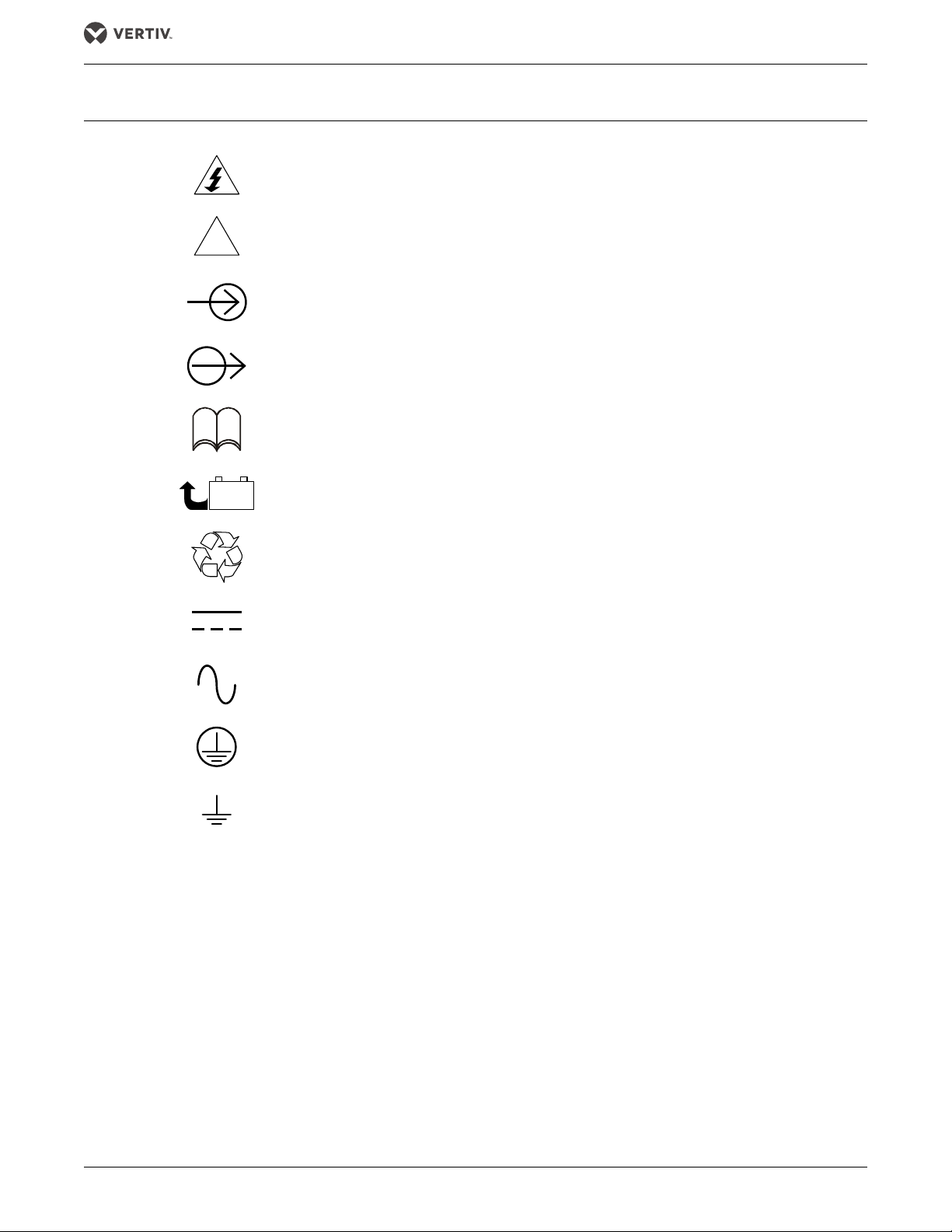
GLOSSARY OF SYMBOLS
!
PbH2SO4
-
+
R
Risk of electrical shock
Indicates caution followed by important instructions
AC input
AC output
Glossary of Symbols
i
Requests the user to consult the manual
Indicates the unit contains a valve-regulated lead acid battery
Recycle
DC voltage
AC voltage
Equipment grounding conductor
Bonded to ground
®
Vertiv |Liebert
EXM™ 10-40kVA, 50/60Hz User Manual 7

Introduction
1.0 INTRODUCTION
The Liebert EXM UPS can be configured as either a fixed-capacity or scalable, transformer-free, online
uninterruptible power system with 208/120V input and 208/120V output capability. The Liebert EXM can
operate with either a 50 or 60Hz input and provide a matching output frequency conversion.
When configured for scalability, the UPS’s capacity can be increased in 20kVA increments. Based on the
configuration, a power module can be set to a redundant operation mode. Contact Vertiv® Liebert Services about
adding capacity.
Optional transformers are available to add 208V isolation or 480V or 600V input capability to the Liebert EXM in
the optional Liebert BDC
™ (
Bypass Distribution Cabinet) and in the optional Liebert EXM Dual Transformer
Cabinet.
The Liebert EXM provides continuous, high-quality AC power to business-critical equipment, such as
telecommunications and data processing equipment. The Liebert EXM supplies power free of the disturbances
and variations in voltage and frequency common to utility power, which is subject to brownouts, blackouts,
surges and sags.
The Liebert EXM utilizes the latest in high-frequency, double-conversion pulse width modulation (PWM)
technology and fully digital controls to enhance its reliability and increase the ease of use.
The 10-40kVA/kW Liebert EXM includes internal batteries to support the load when utility power is not present.
1.1 OPERATOR CONTROL AND DISPLAY PANEL
Information about using the UPS control panel is detailed in SL-26200, available at Liebert’s Web site,
www.liebert.com
Vertiv | Liebert
®
EXM™ 10-40kVA, 50/60Hz User Manual 8

Installation
2.0 INSTALLATION
This section describes the Liebert EXM’s environmental requirements and mechanical considerations that must
be taken into account when planning the positioning and cabling of the UPS equipment.
Because each site is unique, this section presents a guide to general procedures and practices that should be
observed by the installing engineer, rather than step-by-step installation instructions.
NOTICE
Risk of improper installation. Can cause equipment damage.
Do not apply electrical power to the UPS equipment before the commissioning engineer arrives at the installation site.
The UPS must be installed by a properly trained and qualified engineer in accordance with the information contained in
this chapter. All the equipment not referred to in this manual is shipped with details of its own mechanical and electrical
installation information.
NOTE
Three-phase, four-wire input power is required.
NOTE
Input power must be supplied to the Liebert EXM from a properly grounded Wye source. The Liebert EXM is
not for use with impedance grounded systems, corner-grounded systems or high-leg Delta systems. For these
applications, an isolation transformer must be installed between the input power and the Liebert
EXM.
2.1 INITIAL INSPECTIONS
1. While the Liebert EXM and ancillary cabinets are still on the truck, inspect the equipment and shipping container for any signs
of damage or mishandling. Do not attempt to install the system if damage is apparent. If any damage is noted, file a damage
claim with the shipping agency immediately and contact Liebert Services at 1-800-LIEBERT to inform them of the damage
claim and the condition of the equipment.
2. Compare the contents of the shipment with the bill of lading. Report any missing items to the carrier and your local Vertiv
representative immediately.
3. Check the product label on the back of front door and confirm the contents match the UPS model, capacity and main
parameters that were ordered.
®
2.1.1 Storing the UPS and Batteries for Delayed Installation
If the Liebert EXM system will not be installed immediately, it must be stored indoors in a clean, dry and cool
location (see 7.2 - UPS Environmental). If the UPS includes batteries, either internally or in a battery cabinet, the
batteries’ requirements will dictate the storage conditions. Batteries should be unpacked, installed and charged
as soon as possible after delivery.
NOTICE
Risk of failure to properly charge batteries. Can cause permanent damage to batteries and void the warranty.
Batteries will self-discharge during storage. Batteries must be recharged as recommended by the battery manufacturer.
A notice of “Charge Before Date” is affixed to each unit that has batteries inside. The “Charge Before Date” is calculated
based on the batteries being stored at 77°F (25°C). Storage at a higher temperature will increase the rate of self-discharge,
requiring earlier recharge. Consult the battery manufacturer on how to determine when the batteries need to be
recharged.
2.2 PRELIMINARY CHECKS
2.2.1 Identification
The equipment supplied has an identification tag on the back of the main door listing the type and size of the
UPS.
®
Vertiv |Liebert
EXM™ 10-40kVA, 50/60Hz User Manual 9

Installation
!
2.3 UPS LOCATION
2.3.1 Positioning the UPS
Choose a location for the UPS that offers:
• Easy connection to inputs, outputs and auxiliary equipment
• Enough space to service the UPS
• Air circulation sufficient to expel heat produced by UPS
• Protection against moisture and excessive humidity
• Protection against dust and other particulate matter
• Compliance with fire prevention regulations and practices
• Operating environment temperature of 74-80°F (23-27°C) for maximum battery life
2.3.2 Environmental Considerations
Before installing the Liebert EXM, verify that the UPS room satisfies the environmental conditions stipulated in
7.2 - UPS Environmental, paying particular attention to the ambient temperature and air exchange system.
The UPS unit should be installed in a cool, dry, clean-air environment with adequate ventilation to keep the
ambient temperature within the specified operating range 32°F to 104°F (0°C to 40°C).
For optimal UPS system performance and service life, maintain the operating temperature within the range of 7480°F, (23-27°C).
The Liebert EXM is cooled by internal fans. Cooling air enters the unit through the front of the unit and is
exhausted out the top. To permit proper air flow and prevent overheating, do NOT block or cover the ventilation
openings or blow air down onto the unit. The UPS requires 24 in. (610mm) ventilation clearance above the unit.
See Tabl e 20 for details on heat dissipation.
2.4 BATTERY LOCATION
Temperature is a major factor in determining battery life and capacity. Battery manufacturers recommend an
operating temperature of 77°F (25°C). Ambient temperatures warmer than this reduce battery life; temperatures
below this reduces battery capacity. In a typical installation, battery temperature should be maintained between
74°F and 80°F (23-27°C). Batteries should be placed where there are no main heat sources or air inlets to prevent
portions of batteries from being either much warmer or much cooler than other parts of the batteries.
2.5 CONSIDERATIONS IN MOVING THE LIEBERT EXM
Ensure that the UPS weight is within the designated surface weight loading (lb./ft2 or kg/cm2) of any handling
equipment. See Tab le 1 5 for weights of various units.
The Liebert EXM may be rolled on its casters for short distances only. For longer distances, move the UPS with a
forklift or similar equipment to ease the relocation and to reduce vibration.
WARNING
Risk of moving heavy unit. Can cause property damage, injury and death.
Ensure that any equipment that will be used to move the Liebert EXM has sufficient lifting capacity. The
Liebert EXM’s weight ranges from 809 to 956 lb. (367 to 434kg) without batteries. Refer to Ta ble 1 for the
unit’s weight with batteries.
The UPS presents a tipping hazard. Do not tilt the Liebert EXM more than 15 degrees from vertical.
The UPS is fitted with casters—Take care to prevent movement when unbolting the equipment from its
shipping pallet. Ensure adequate personnel and lifting equipment are available when taking the Liebert
EXM off its shipping pallet.
Vertiv | Liebert
®
EXM™ 10-40kVA, 50/60Hz User Manual 10
Installation
!
!
!
!
!
AVERTISSEMENT
Le poids élevé de l'appareil peut entraîner des dommages matériels, des blessures et même la mort.
Veillez à ce que les équipements utilisés pour déplacer le système EXM de Liebert possèdent une
capacité nominale suffisante. Le poids du système EXM de Liebert varie entre 367 et 434 kg (809 et 956
lb) sans les batteries. Reportez-vous au Tab leau 1 pour connaître le poids de l'appareil avec les batteries.
Le système ASC présente un risque de renversement. N'inclinez pas le système EXM de Liebert à plus de
15 degrés de la verticale.
Comme le système ASC est équipé de roulettes, veillez à éviter les mouvements involontaires lorsque
vous déboulonnez l'équipement de sa palette d'expédition. Veillez à ce qu'un personnel approprié et un
dispositif de levage soient disponibles lorsque vous retirez le système EXM de Liebert de la palette
d'expédition.
WARNING
Risk of heavy unit tipping over while being moved. Can cause property damage, injury and death.
The casters are strong enough for movement across even surfaces only. Casters may fail if they are
subjected to shock loading, such as being dropped or rolled over holes in the floor or obstructions. Such
failure may cause the unit to tip over, injuring personnel and damaging the equipment.
AVERTISSEMENT
Le centre de gravité élevé de l'appareil présente un risque de renversement lors des déplacements, peut
entraîner des dommages matériels, des blessures et même la mort.
Les roulettes sont suffisamment résistantes pour le déplacement sur des surfaces planes uniquement.
Les roulettes peuvent être endommagées si vous les soumettez à des impacts, notamment en cas de
chute ou de passage sur des obstacles ou trous dans le plancher. Une telle défaillance peut causer le
renversement de l'appareil, qui risque de blesser le personnel et d'endommager l'équipement.
Final Positioning
When the equipment has been finally positioned, ensure that the adjustable stops are set so that the UPS will
remain stationary and stable (see 4.0 - Installation Drawings).
The Liebert EXM and its auxiliary cabinets must be installed on a concrete or equivalent, non-resilient floor.
2.6 MECHANICAL CONSIDERATIONS
The Liebert EXM is constructed with a steel frame and removable panels. Top and side panels are secured to the
chassis by screws. The doors may be opened for access to power connection bars, auxiliary terminal blocks and
power switches.
The UPS comes with an Operator Control Panel that provides basic operational status and alarm information.
The cabinet houses the power components. Cooling is provided by internal fans. The unit sits on four casters.
Adjustable stops are provided to prevent the UPS from moving once it has been moved to its final position.
WARNING
Risk of heavy units tipping over while being moved. Can cause property damage, injury and death.
Vertiv® recommends lifting the units by installing four eyebolts in the factory-fabricated holes, one at
each corner of the unit, attaching cables or similar strapping to the eyebolts and lifting with a suitable
mechanism.
AVERTISSEMENT
Le centre de gravité élevé des appareils présente un risque de renversement lors des déplacements, peut
entraîner des dommages matériels, des blessures et même la mort.
Vertiv® recommande de soulever les appareils en installant quatre anneaux de levage dans les ouvertures
fabriquées en usine, avec un anneau dans chaque coin de l'appareil, pour ensuite fixer les câbles ou
sangles aux anneaux afin d'effectuer le levage à l'aide d'un mécanisme approprié.
Vertiv |Liebert
®
EXM™ 10-40kVA, 50/60Hz User Manual 11
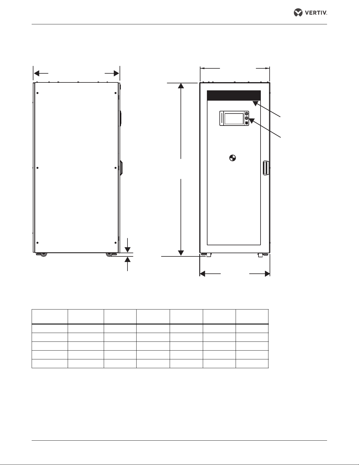
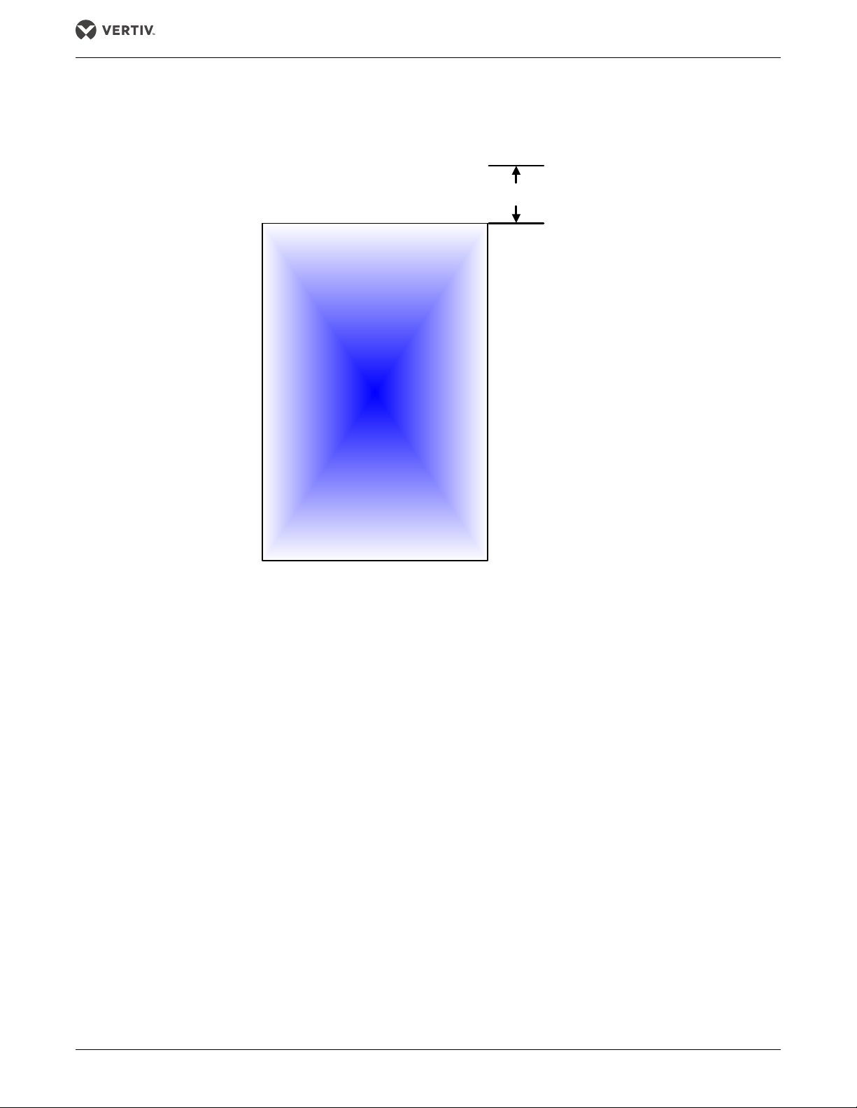
2.6.1 Dimensions
39.5" (1000mm)
31.5"
(600mm)
Without Side Panels
Front
Display
Vent Screen
Front and Back
Center
of Gravity
78.7"
(2000mm)
1.56"
(40mm)
LEFT SIDE
FRONT
Overall
31.8
(808mm)
Figure 1 UPS dimensions
Installation
Table 1 Weights for Liebert EXM 10-40kVA frame
UPS Rating
kVA
10 684 (310) 1212 (550) 1308 (593) 1716 (778) 1332 (812) 1644 (746)
15 684 (310) 1212 (550) 1308 (593) 1716 (778) 1332 (812) 1644 (746)
20 684 (310) 1212 (550) 1308 (593) 1716 (778) 1332 (812) 1644 (746)
30 758 (344) N/A 1382 (627) 1790 (812) 1406 (638) 1718 (779)
40 758 (344) N/A N/A 1790 (812) N/A 1718 (779)
Add 100 lb. (45 kg) for shipping weights.
No Internal
Batteries 12HX100 12HX150E 12HX205 HR1500 HR2000
2.6.2 Clearances
Provide at least the minimum clearance required by NEC on all sides of Liebert EXM, including 36" (914mm) in
front, to permit routine tightening of power terminations within the UPS and free passage of personnel with the
door fully opened. Depending on the floor anchoring system used, up to 5" (127mm) may be required in the rear
of the UPS.
There are no ventilation grilles on the sides or back of the UPS.
®
Vertiv | Liebert
EXM™ 10-40kVA, 50/60Hz User Manual 12
Installation
Liebert
EXM
0 to 5" (127mm)
Rear clearance
depends on
anchoring method
0" Required
Minimum of 36" (914mm) required
for foot traffic with door fully open
FRONT
REAR
0" Required
Leave a minimum of 24 in. (610mm) between the top of the UPS frame and the ceiling to permit adequate air
circulation above the unit. Vertiv® recommends against using air conditioning or other systems that blow air onto
the top of the unit.
Figure 2 Clearances—Front, side and rear
2.6.3 Floor Installation
If the Liebert EXM is to be placed on a raised floor, the UPS should be mounted on a pedestal that will support
the equipment point loading. Refer to the bottom view in Figure 1 to design this pedestal.
®
Vertiv |Liebert
EXM™ 10-40kVA, 50/60Hz User Manual 13
Installation
2.6.4 Cable Entry
Cables can enter the Liebert EXM from the top or bottom through removable metal plates.
Some plates have factory-punched holes and others are designed to allow the personnel to punch holes for
fitting and securing the conduit. Once the conduit holes are punched, these plates should be reattached to the
UPS. The conduit size and wiring method must be in accordance with all local, regional and national codes and
regulations, including NEC ANSI/NFPA 70.
The UPS must be accessible from the front to allow personnel to complete the cable connections and make
necessary adjustments.
NOTE
When installing the UPS, the customer must provide a disconnect with overcurrent protection at the output of
the UPS.
Figure 3 Cable entry locations
15.6"
(396mm)
4"
(102mm)
1.6"
(41mm)
Top Power
Cable Entry
Top Control
Cable Entry
TOP VIEW
26.2"
(665mm)
2.8"
(71mm)
Casters
Bottom
Control Cable
Entry
Bottom
Power Cable
Entry
1.6"
(41mm)
28.3"
(719mm)
Casters
34.3"
(872mm)
20.4" (518mm)
BOTTOM VIEW
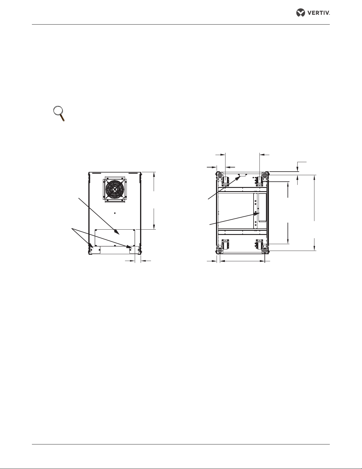
2.7 AUXILIARY CABINETS
The Liebert EXM 10-40kVA UPS can be integrated with the following auxiliary cabinets:
Battery Cabinets—Optional Liebert EXM Battery Cabinets™ are available for each Liebert EXM model to provide
extended run times, large battery system solutions and optional integrated Alber® battery monitoring. The
battery cabinets are designed to be bolted to the left side of the UPS (see Figure 4). Refer to SL-25651, the
Liebert EXM Battery Cabinet manual, for details.
Maintenance Bypass Cabinets—Optional Liebert EXM Bypass Cabinets™ are available to provide a full or partial
wraparound maintenance bypass for servicing the UPS. Liebert bypass cabinets are designed to be bolted to the
right side of the UPS (see Figure 4). Refer to SL-25652, the Liebert EXM Maintenance Bypass Cabinet manual,
for further details.
Bypass Distribution Cabinet—Optional Liebert EXM Bypass Distribution Cabinets™ are available to provide a
full wraparound maintenance bypass for servicing the UPS with optional input transformer and output
distribution. Liebert bypass cabinets are designed to be bolted to the right side of the UPS (see Figure 4). Refer
to SL-25653, the Liebert EXM Bypass Distribution Cabinet manual, for further details.
Paralleling Cabinet—Optional Liebert EXM Paralleling Cabinets™ are available to provide connections enabling
parallel operation of up to three Liebert EXM UPS’s in applications offering increased capacity and redundant
protection (1+1, 2+0, 2+1). A partial wraparound maintenance bypass for servicing of the parallel UPS system is
included. Refer to SL-25654, the Liebert EXM Paralleling Cabinet manual, for further details.
Vertiv | Liebert
®
EXM™ 10-40kVA, 50/60Hz User Manual 14
Installation
Liebert
EXM
Bypass
Distribution
Cabinet
or
Maintenance
Bypass
Cabinet
Bypass
Distribution
Cabinet
Liebert
EXM
Battery
Cabinet
Battery
Cabinet
Liebert
EXM
Battery
Cabinet
Liebert EXM connected only
to Liebert BDC/MBC
(The Liebert BDC/MBC must be on right side of
the Liebert EXM)
Liebert EXM connected to Liebert BDC/MBC and Battery Cabinets
(BDC/MBC must be on the right side of the Liebert EXM)
(Battery Cabinets must be on the left side of the Liebert EXM)
ALL UNITS VIEWED FROM ABOVE
Liebert EXM connected to Battery Cabinet
(Battery Cabinets must be on the left side of the
Liebert EXM)
Layouts shown are typical. Not all
auxiliary cabinets are shown. Refer
to the submittal drawings for the
exact configuration of your system.
Dual Transformer Cabinet—Optional Liebert EXM Dual Transformer Cabinets™ are available to provide step-
down voltage transformation for dual-input UPS applications. Refer to SL-25655, the Liebert EXM Dual
Transformer Cabinet manual, for further details.
System Composition
A UPS system can comprise a number of optional equipment cabinets, depending on the system design
requirements—e.g., UPS cabinet, External Battery Cabinet and External Bypass Cabinet. All cabinets used will be
the same height and will be designed to be positioned side-by-side to form an aesthetically appealing equipment
suite.
Figure 4 Cabinet arrangement
Vertiv |Liebert
®
EXM™ 10-40kVA, 50/60Hz User Manual 15
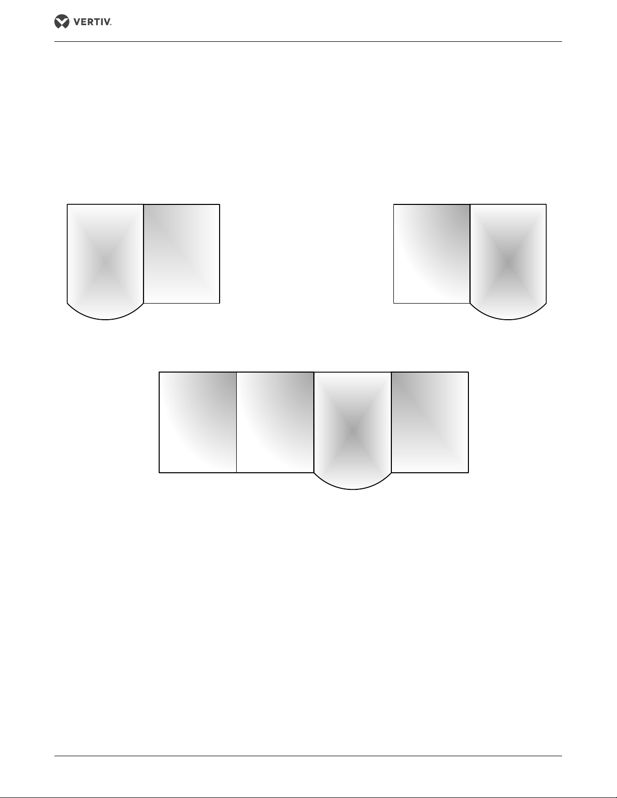
2.8 POWER MODULE ASSEMBLY
Figure 5 Power Module Assembly indicators and controls
Fault LED
Battery Start Button
The Battery Start button allows starting the UPS on battery.
The Run LED is illuminated Green when the Liebert Power Module Assembly is operating normally.
The Fault LED will illuminate red when the Liebert Power Module Assembly has a problem.
Table 2 LED indications on power module assembly
LED Status Indication
Run LED (Green)
Flashing Green The inverter is starting, but has no output yet.
Constant Green The inverter has started to supply power.
OFF The inverter has not started up.
Fault LED (Red)
Auxiliary power failure (15V or 24V), rectifier overtemperature, rectifier failure (including battery SCR short circuit), battery
Constant Red
Flashing Red
converter failure, soft start failure, main circuit back feed, abnormal input current, inverter failure, output short circuit,
bypass SCR short circuit fault, inverter relay short circuit fault, abnormal bus voltage, module not ready, module ID out of
range and duplicated module ID.
Charger failure, abnormal main circuit voltage, abnormal main circuit frequency, main circuit undervoltage, main circuit
reverse phase, battery unavailable, reverse battery, input zero-loss, current sharing failure, module overload, inverter relay
disconnection fault, bypass SCR disconnection fault and input fuse blown.
DIP Switches
Run LED
Ready Switch
Installation
OFF No above failures or alarms.
®
Vertiv | Liebert
EXM™ 10-40kVA, 50/60Hz User Manual 16
Installation
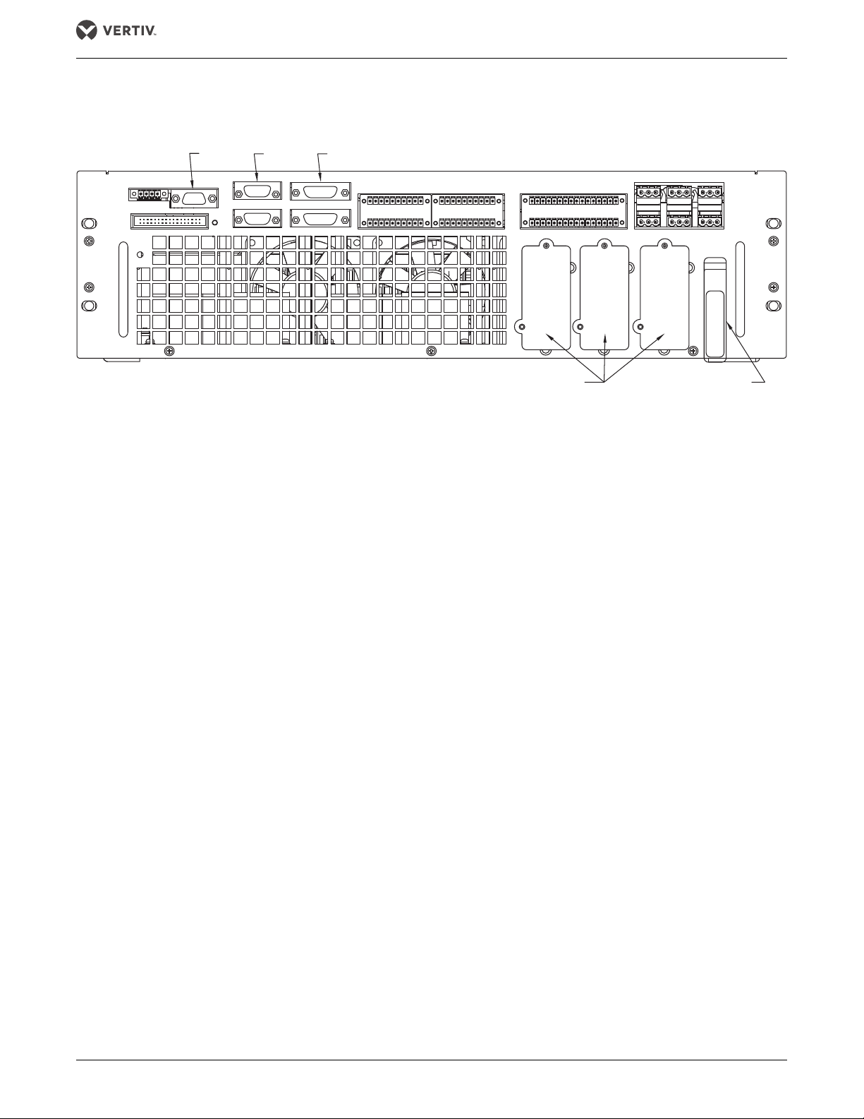
Liebert IntelliSlot
Bays 1, 2, 3
Ready Switch
DB9
DB9
DB15
See Figures 15- 18 for details.
2.9 STATIC BYPASS ASSEMBLY
Figure 6 Static Bypass Assembly connections
The Static Bypass Assembly has three Liebert IntelliSlot™ interface card bays and connections for optional
ancillary cabinets and for other options.
Vertiv |Liebert
®
EXM™ 10-40kVA, 50/60Hz User Manual 17

Electrical Connections—UPS
!
!
3.0 ELECTRICAL CONNECTIONS—UPS
The UPS requires both power and control cabling once it has been mechanically installed. All control cables
must run separate from power cables in metal conduits or metal ducts that are electrically bonded to the
metalwork of the cabinets to which they are connected.
WARNING
Risk of electric shock. Can cause property damage, injury and death.
Before connecting input power to the Liebert EXM, ensure that you are aware of the location and
operation of the overcurrent protection devices that connect the UPS input/bypass supply to the power
distribution panel.
De-energize and lockout or tagout all incoming high- and low-voltage power circuits before installing
cables or making any electrical connections.
AVERTISSEMENT
Risque de décharge électrique pouvant entraîner des dommages matériels, des blessures et même la
mort.
Avant de procéder au branchement de l'alimentation d'entrée du système EXM de Liebert, veillez à
prendre connaissance de l'emplacement et du fonctionnement des dispositifs de protection de
surintensité qui raccordent l'alimentation d'entrée ou de dérivation du système ASC au panneau de
distribution électrique.
Coupez l'alimentation et appliquez le verrouillage ou l'étiquetage à tous les circuits d'alimentation haute
tension et basse tension avant d'installer les câbles ou d'effectuer tout autre branchement électrique.
3.1 POWER CABLING
3.1.1 Lug Size and Cable Rating
The main factors affecting the choice and size of cable are voltage, current (also taking into account
overcurrent), room temperature and conditions of installation of the cable. Refer to ANSI/NFPA 70.
The power cables of the system must be sized with respect to the following description:
• UPS input cables—The UPS input cables must be sized for the maximum input current, including the maximum battery
recharge current, given in Table 16, with respect to the unit rating and the input AC voltage.
• UPS bypass and output cables—The bypass and output cables must be sized for the nominal output current, given in
Table 16, with respect to the unit rating and the output AC voltage.
• Battery cables—See the Liebert EXM External Battery Cabinet manual, SL-25651, for battery installation guidelines and
instructions. The manual ships with the battery cabinet and is available at Liebert’s Web site: www.liebert.com
NOTE
Table 16 gives nominal currents for determining the size of UPS power cables. Other important factors to
consider include cable route length and coordination with protective devices.
The power cables can be sized to suit the UPS unit rating according to Table 16.
Torque Requirements
Refer to Tables 3 and 4 for lug size and torque requirements.
Table 3 Busbars (for power wiring)
Bolt Shaft Size Lb-in (Nm)
3/8" (M10) 192 (22)
Table 4 Terminal block with compression lugs (for control wiring)
AWG Wire Size or Range Lb-in (Nm)
#22 - #14 3.5 to 5.3 (0.4 to 0.6)
®
Vertiv | Liebert
EXM™ 10-40kVA, 50/60Hz User Manual 18

Electrical Connections—UPS
3.2 EXTERNAL PROTECTIVE DEVICES
For safety concerns, it is necessary to install external circuit breakers or other protective devices for the input AC
supply of the UPS system. This section provides generic practical information for qualified installation engineers.
The installation engineers should be knowledgeable about regulatory wiring standards and the equipment to be
installed.
To reduce the risk of fire, connect only to a circuit provided with branch circuit overcurrent protection in
accordance with NEC ANSI/NFPA 70.
3.2.1 Rectifier and Bypass Input Supply of the UPS
Overcurrents
Install suitable protective devices in the distribution unit of the incoming mains supply, considering the power
cable current-carrying capacity and overload capacity of the system. Generally, the magnetic circuit breaker with
IEC60947-2 tripping curve C (normal) at the 125% of the nominal current listed in Tabl e 16 is recommended.
Split bypass: In case a split bypass is used, separate protective devices should be installed for the rectifier input
and bypass input in the incoming mains distribution panel. A shunt trip coil of 120V must be installed in the
bypass input breaker if the system does not include a Liebert Bypass Cabinet.
NOTE
The rectifier input and bypass input must use the same neutral line.
Earth Leakage, RCD Devices
Any residual current detector (RCD) installed upstream of the UPS input supply:
• Must be sensitive to DC unidirectional pulses (Class A)
• Must be insensitive to transient current pulses, and
• Must have an average sensitivity, adjustable between 0.3 and 1A.
To avoid false alarms, earth leakage monitoring devices when used in systems with split bypass input or when
used in paralleled UPS configurations, must be located upstream of the common neutral sinking point.
Alternatively, the device must monitor the combined four-wire rectifier and split bypass input currents.
3.2.2 UPS Output
If an external distribution panel is used for load distribution, the selection of protective devices must provide
discrimination with those that are used at the input to the UPS (see Table 21).
3.2.3 UPS Input Configuration
By default, the Liebert EXM ships with internal links installed between the bypass input and main (rectifier) input
(single input configuration).
Figures 7 and 8 show the Liebert EXM in a split bypass (single source dual-input) configuration. In this
configuration, the static bypass and the maintenance bypass lines are supplied by the same source using
separate feeds. Both feeds must be protected externally with properly sized protective devices.
To wire the Liebert EXM as a single source dual-input UPS, remove the links and wire the bypass feed to the
bypass busbars, then wire the main feed to the main busbars (see Figure 10).
Vertiv |Liebert
®
EXM™ 10-40kVA, 50/60Hz User Manual 19
 Loading...