

Page 1

Liebert® EXL S1™ Touchscreen Control Panel
User Manual
™
Page 2

Page 3

TABLE OF CONTENTS
1.0 INTRODUCTION. . . . . . . . . . . . . . . . . . . . . . . . . . . . . . . . . . . . . . . . . . . . . . . . . . . . . . . . . . . . . . .1
2.0 NAVIGATING THROUGH THE TOUCHSCREEN CONTROL PANEL . . . . . . . . . . . . . . . . 2
2.1 Restrict Physical Access with Barriers or Set Log-In Codes . . . . . . . . . . . . . . . . . . . . . . . . . . . . . . . . . . . . . . . . .2
2.2 Touchscreen Control Panel Components. . . . . . . . . . . . . . . . . . . . . . . . . . . . . . . . . . . . . . . . . . . . . . . . . . . . . . . . . . 4
2.2.1 Context Menus . . . . . . . . . . . . . . . . . . . . . . . . . . . . . . . . . . . . . . . . . . . . . . . . . . . . . . . . . . . . . . . . . . . . . . . . . . . . . . . . . . . 6
2.3 SYSTEM PANE—Mimic Display Components. . . . . . . . . . . . . . . . . . . . . . . . . . . . . . . . . . . . . . . . . . . . . . . . . . . . . . .8
2.3.1 UNIT STATUS Pane Components . . . . . . . . . . . . . . . . . . . . . . . . . . . . . . . . . . . . . . . . . . . . . . . . . . . . . . . . . . . . . . . . . 10
2.4 Customizing the Display . . . . . . . . . . . . . . . . . . . . . . . . . . . . . . . . . . . . . . . . . . . . . . . . . . . . . . . . . . . . . . . . . . . . . . . . .14
2.4.1 Remove a Layout . . . . . . . . . . . . . . . . . . . . . . . . . . . . . . . . . . . . . . . . . . . . . . . . . . . . . . . . . . . . . . . . . . . . . . . . . . . . . . . . .17
2.4.2 Using the Edit Icon to Customize Layout. . . . . . . . . . . . . . . . . . . . . . . . . . . . . . . . . . . . . . . . . . . . . . . . . . . . . . . . . . .17
2.4.3 Edit the UNIT STATUS Panel with the Edit Icon . . . . . . . . . . . . . . . . . . . . . . . . . . . . . . . . . . . . . . . . . . . . . . . . . . . .19
2.4.4 Setting DISPLAY PROPERTIES . . . . . . . . . . . . . . . . . . . . . . . . . . . . . . . . . . . . . . . . . . . . . . . . . . . . . . . . . . . . . . . . . . . 20
2.4.5 Setting Date, Time and Time Zone. . . . . . . . . . . . . . . . . . . . . . . . . . . . . . . . . . . . . . . . . . . . . . . . . . . . . . . . . . . . . . . . .21
2.5 Changing Date, Time and Measurement Formats. . . . . . . . . . . . . . . . . . . . . . . . . . . . . . . . . . . . . . . . . . . . . . . . . 23
2.5.1 Change the Date Format . . . . . . . . . . . . . . . . . . . . . . . . . . . . . . . . . . . . . . . . . . . . . . . . . . . . . . . . . . . . . . . . . . . . . . . . . 24
2.5.2 Change the Time Format . . . . . . . . . . . . . . . . . . . . . . . . . . . . . . . . . . . . . . . . . . . . . . . . . . . . . . . . . . . . . . . . . . . . . . . . . 24
2.5.3 Change the Measurement System . . . . . . . . . . . . . . . . . . . . . . . . . . . . . . . . . . . . . . . . . . . . . . . . . . . . . . . . . . . . . . . . 24
2.6 Create or Modify Custom Labels. . . . . . . . . . . . . . . . . . . . . . . . . . . . . . . . . . . . . . . . . . . . . . . . . . . . . . . . . . . . . . . . . 24
3.0 OPERATION. . . . . . . . . . . . . . . . . . . . . . . . . . . . . . . . . . . . . . . . . . . . . . . . . . . . . . . . . . . . . . . . . 27
3.1 Log In to the Touchscreen Control Panel. . . . . . . . . . . . . . . . . . . . . . . . . . . . . . . . . . . . . . . . . . . . . . . . . . . . . . . . . 27
3.2 Operator Controls. . . . . . . . . . . . . . . . . . . . . . . . . . . . . . . . . . . . . . . . . . . . . . . . . . . . . . . . . . . . . . . . . . . . . . . . . . . . . . . 28
3.2.1 LIFE™ Services . . . . . . . . . . . . . . . . . . . . . . . . . . . . . . . . . . . . . . . . . . . . . . . . . . . . . . . . . . . . . . . . . . . . . . . . . . . . . . . . . . . 28
3.3 OPERATE Menu Commands. . . . . . . . . . . . . . . . . . . . . . . . . . . . . . . . . . . . . . . . . . . . . . . . . . . . . . . . . . . . . . . . . . . . . 29
3.3.1 OPERATE Menu—Silence an Alarm. . . . . . . . . . . . . . . . . . . . . . . . . . . . . . . . . . . . . . . . . . . . . . . . . . . . . . . . . . . . . . . 29
3.3.2 OPERATE Menu—Inverter On . . . . . . . . . . . . . . . . . . . . . . . . . . . . . . . . . . . . . . . . . . . . . . . . . . . . . . . . . . . . . . . . . . . . 30
3.3.3 OPERATE Menu—Inverter Off . . . . . . . . . . . . . . . . . . . . . . . . . . . . . . . . . . . . . . . . . . . . . . . . . . . . . . . . . . . . . . . . . . . . .31
3.3.4 OPERATE Menu—Reset Fault . . . . . . . . . . . . . . . . . . . . . . . . . . . . . . . . . . . . . . . . . . . . . . . . . . . . . . . . . . . . . . . . . . . . .31
3.3.5 OPERATE Menu—Suspended Time Remaining. . . . . . . . . . . . . . . . . . . . . . . . . . . . . . . . . . . . . . . . . . . . . . . . . . . . 32
3.3.6 OPERATE Menu—Energy Saving Mode Activation . . . . . . . . . . . . . . . . . . . . . . . . . . . . . . . . . . . . . . . . . . . . . . . . 32
3.4 Audible Alarm Enabled or Disabled . . . . . . . . . . . . . . . . . . . . . . . . . . . . . . . . . . . . . . . . . . . . . . . . . . . . . . . . . . . . . . 33
3.5 LIFE™ Services—Context Menu and LIFE Services Function Menu . . . . . . . . . . . . . . . . . . . . . . . . . . . . . . . . 34
4.0 VIEWING UPS STATUS. . . . . . . . . . . . . . . . . . . . . . . . . . . . . . . . . . . . . . . . . . . . . . . . . . . . . . . 35
4.1 Viewing UPS Data with the Status Gauge . . . . . . . . . . . . . . . . . . . . . . . . . . . . . . . . . . . . . . . . . . . . . . . . . . . . . . . . 35
4.2 Viewing UPS Data with the Status Panel . . . . . . . . . . . . . . . . . . . . . . . . . . . . . . . . . . . . . . . . . . . . . . . . . . . . . . . . . 37
4.3 Logs—Events and Log-In Times . . . . . . . . . . . . . . . . . . . . . . . . . . . . . . . . . . . . . . . . . . . . . . . . . . . . . . . . . . . . . . . . . 43
4.3.1 Logs—Filtering and Sorting Events . . . . . . . . . . . . . . . . . . . . . . . . . . . . . . . . . . . . . . . . . . . . . . . . . . . . . . . . . . . . . . . 44
4.4 Logs—Exporting Event and Audit Logs . . . . . . . . . . . . . . . . . . . . . . . . . . . . . . . . . . . . . . . . . . . . . . . . . . . . . . . . . . 45
5.0 VIEWING UPS COMPONENT STATUS . . . . . . . . . . . . . . . . . . . . . . . . . . . . . . . . . . . . . . . . . 46
6.0 STATUS BAR COMPOSITION . . . . . . . . . . . . . . . . . . . . . . . . . . . . . . . . . . . . . . . . . . . . . . . . . 48
6.1 Status Bar Messages. . . . . . . . . . . . . . . . . . . . . . . . . . . . . . . . . . . . . . . . . . . . . . . . . . . . . . . . . . . . . . . . . . . . . . . . . . . . 48
7.0 LIEBERT EXL S1 EVENTS, WARNINGS AND ALARMS . . . . . . . . . . . . . . . . . . . . . . . . . . . 52
Vertiv™|Liebert® EXL™ S1 Touchscreen Control User Manual | Rev. 1 | 12/2017 | i
Page 4

FIGURES
Figure 1 Touchscreen Control Panel components . . . . . . . . . . . . . . . . . . . . . . . . . . . . . . . . . . . . . . . . . . . . . . . . . . . . . . . 1
Figure 2 Opening screens . . . . . . . . . . . . . . . . . . . . . . . . . . . . . . . . . . . . . . . . . . . . . . . . . . . . . . . . . . . . . . . . . . . . . . . . . . . . . .3
Figure 3 Interface overview—STATUS screen; graphic display . . . . . . . . . . . . . . . . . . . . . . . . . . . . . . . . . . . . . . . . . . 4
Figure 4 Control display by access level—if PIN’s are required . . . . . . . . . . . . . . . . . . . . . . . . . . . . . . . . . . . . . . . . . . 4
Figure 5 Context Menus. . . . . . . . . . . . . . . . . . . . . . . . . . . . . . . . . . . . . . . . . . . . . . . . . . . . . . . . . . . . . . . . . . . . . . . . . . . . . . . 6
Figure 6 Mimic display, normal operation, default view/unit view . . . . . . . . . . . . . . . . . . . . . . . . . . . . . . . . . . . . . . . . 9
Figure 7 Mimic display, normal operation, system view . . . . . . . . . . . . . . . . . . . . . . . . . . . . . . . . . . . . . . . . . . . . . . . . .10
Figure 8 UNIT STATUS pane components—Graphic display . . . . . . . . . . . . . . . . . . . . . . . . . . . . . . . . . . . . . . . . . . . . 11
Figure 9 UNIT STATUS pane—Load details; graphic display . . . . . . . . . . . . . . . . . . . . . . . . . . . . . . . . . . . . . . . . . . . . 11
Figure 10 UNIT STATUS pane—Input details; graphic display. . . . . . . . . . . . . . . . . . . . . . . . . . . . . . . . . . . . . . . . . . . .12
Figure 11 UNIT STATUS pane—Bypass details; graphic display . . . . . . . . . . . . . . . . . . . . . . . . . . . . . . . . . . . . . . . . . .12
Figure 12 UNIT STATUS pane—Battery and cabinet details; graphic display. . . . . . . . . . . . . . . . . . . . . . . . . . . . . .13
Figure 13 UNIT STATUS pane—Environmental details; graphic display. . . . . . . . . . . . . . . . . . . . . . . . . . . . . . . . . . .13
Figure 14 Customize the display. . . . . . . . . . . . . . . . . . . . . . . . . . . . . . . . . . . . . . . . . . . . . . . . . . . . . . . . . . . . . . . . . . . . . . . .15
Figure 15 Set number of panes and choose data . . . . . . . . . . . . . . . . . . . . . . . . . . . . . . . . . . . . . . . . . . . . . . . . . . . . . . . .16
Figure 16 Edit UNIT STATUS panel . . . . . . . . . . . . . . . . . . . . . . . . . . . . . . . . . . . . . . . . . . . . . . . . . . . . . . . . . . . . . . . . . . . . .17
Figure 17 Change panel content . . . . . . . . . . . . . . . . . . . . . . . . . . . . . . . . . . . . . . . . . . . . . . . . . . . . . . . . . . . . . . . . . . . . . . . .18
Figure 18 Resize, remove or rearrange a panel . . . . . . . . . . . . . . . . . . . . . . . . . . . . . . . . . . . . . . . . . . . . . . . . . . . . . . . . . .19
Figure 19 Edit UNIT STATUS panel . . . . . . . . . . . . . . . . . . . . . . . . . . . . . . . . . . . . . . . . . . . . . . . . . . . . . . . . . . . . . . . . . . . . 20
Figure 20 Date and time settings . . . . . . . . . . . . . . . . . . . . . . . . . . . . . . . . . . . . . . . . . . . . . . . . . . . . . . . . . . . . . . . . . . . . . . .21
Figure 21 Time Zone drop-down menu. . . . . . . . . . . . . . . . . . . . . . . . . . . . . . . . . . . . . . . . . . . . . . . . . . . . . . . . . . . . . . . . . 22
Figure 22 Change the date . . . . . . . . . . . . . . . . . . . . . . . . . . . . . . . . . . . . . . . . . . . . . . . . . . . . . . . . . . . . . . . . . . . . . . . . . . . . 22
Figure 23 Change the time . . . . . . . . . . . . . . . . . . . . . . . . . . . . . . . . . . . . . . . . . . . . . . . . . . . . . . . . . . . . . . . . . . . . . . . . . . . . 23
Figure 24 Date/Time format and Measurement System choices. . . . . . . . . . . . . . . . . . . . . . . . . . . . . . . . . . . . . . . . . 24
Figure 25 CUSTOM LABELS page . . . . . . . . . . . . . . . . . . . . . . . . . . . . . . . . . . . . . . . . . . . . . . . . . . . . . . . . . . . . . . . . . . . . . 25
Figure 26 Custom Labels for Network Interfaces . . . . . . . . . . . . . . . . . . . . . . . . . . . . . . . . . . . . . . . . . . . . . . . . . . . . . . . 26
Figure 27 Set a PIN . . . . . . . . . . . . . . . . . . . . . . . . . . . . . . . . . . . . . . . . . . . . . . . . . . . . . . . . . . . . . . . . . . . . . . . . . . . . . . . . . . . 27
Figure 28 Log in screen . . . . . . . . . . . . . . . . . . . . . . . . . . . . . . . . . . . . . . . . . . . . . . . . . . . . . . . . . . . . . . . . . . . . . . . . . . . . . . . 28
Figure 29 OPERATE Function Menu screen . . . . . . . . . . . . . . . . . . . . . . . . . . . . . . . . . . . . . . . . . . . . . . . . . . . . . . . . . . . . 29
Figure 30 Inverter On command, single UPS configuration . . . . . . . . . . . . . . . . . . . . . . . . . . . . . . . . . . . . . . . . . . . . . . 30
Figure 31 Inverter On command, parallel UPS configuration. . . . . . . . . . . . . . . . . . . . . . . . . . . . . . . . . . . . . . . . . . . . . 30
Figure 32 Inverter Off command, single UPS configuration. . . . . . . . . . . . . . . . . . . . . . . . . . . . . . . . . . . . . . . . . . . . . . . 31
Figure 33 Inverter Off command, parallel UPS configuration . . . . . . . . . . . . . . . . . . . . . . . . . . . . . . . . . . . . . . . . . . . . .31
Figure 34 Reset fault command. . . . . . . . . . . . . . . . . . . . . . . . . . . . . . . . . . . . . . . . . . . . . . . . . . . . . . . . . . . . . . . . . . . . . . . . 32
Figure 35 Activating Energy Savings Mode . . . . . . . . . . . . . . . . . . . . . . . . . . . . . . . . . . . . . . . . . . . . . . . . . . . . . . . . . . . . 33
Figure 36 LIFE Services contact . . . . . . . . . . . . . . . . . . . . . . . . . . . . . . . . . . . . . . . . . . . . . . . . . . . . . . . . . . . . . . . . . . . . . . . 34
Figure 37 LIFE Services—Menus . . . . . . . . . . . . . . . . . . . . . . . . . . . . . . . . . . . . . . . . . . . . . . . . . . . . . . . . . . . . . . . . . . . . . . 34
Figure 38 Default Status Gauge view . . . . . . . . . . . . . . . . . . . . . . . . . . . . . . . . . . . . . . . . . . . . . . . . . . . . . . . . . . . . . . . . . . 35
Figure 39 Access Status Gauge settings . . . . . . . . . . . . . . . . . . . . . . . . . . . . . . . . . . . . . . . . . . . . . . . . . . . . . . . . . . . . . . . 36
Figure 40 Status Gauge settings options. . . . . . . . . . . . . . . . . . . . . . . . . . . . . . . . . . . . . . . . . . . . . . . . . . . . . . . . . . . . . . . 37
Figure 41 UNIT STATUS—Load details . . . . . . . . . . . . . . . . . . . . . . . . . . . . . . . . . . . . . . . . . . . . . . . . . . . . . . . . . . . . . . . . 38
Figure 42 UNIT STATUS—Input details . . . . . . . . . . . . . . . . . . . . . . . . . . . . . . . . . . . . . . . . . . . . . . . . . . . . . . . . . . . . . . . . 39
Figure 43 UNIT STATUS—Bypass details . . . . . . . . . . . . . . . . . . . . . . . . . . . . . . . . . . . . . . . . . . . . . . . . . . . . . . . . . . . . . . 40
Figure 44 UNIT STATUS—Battery details . . . . . . . . . . . . . . . . . . . . . . . . . . . . . . . . . . . . . . . . . . . . . . . . . . . . . . . . . . . . . . .41
Vertiv™|Liebert® EXL™ S1 Touchscreen Control User Manual | Rev. 1 | 12/2017 | ii
Page 5

Figure 45 UNIT STATUS—Environmental details . . . . . . . . . . . . . . . . . . . . . . . . . . . . . . . . . . . . . . . . . . . . . . . . . . . . . . . 42
Figure 46 View alarms, events, log-out times . . . . . . . . . . . . . . . . . . . . . . . . . . . . . . . . . . . . . . . . . . . . . . . . . . . . . . . . . . . 43
Figure 47 Sorting and filtering events . . . . . . . . . . . . . . . . . . . . . . . . . . . . . . . . . . . . . . . . . . . . . . . . . . . . . . . . . . . . . . . . . . 44
Figure 48 Exporting logs . . . . . . . . . . . . . . . . . . . . . . . . . . . . . . . . . . . . . . . . . . . . . . . . . . . . . . . . . . . . . . . . . . . . . . . . . . . . . . 45
Figure 49 Component status—STATUS Menu . . . . . . . . . . . . . . . . . . . . . . . . . . . . . . . . . . . . . . . . . . . . . . . . . . . . . . . . . . 46
Figure 50 UNIT STATUS—Main Input details. . . . . . . . . . . . . . . . . . . . . . . . . . . . . . . . . . . . . . . . . . . . . . . . . . . . . . . . . . . 46
Figure 51 UNIT STATUS details . . . . . . . . . . . . . . . . . . . . . . . . . . . . . . . . . . . . . . . . . . . . . . . . . . . . . . . . . . . . . . . . . . . . . . . 47
TABLES
Table 1 Available display properties by access level if PIN’s are required . . . . . . . . . . . . . . . . . . . . . . . . . . . . . . 20
Table 2 Additional custom label choices for Settings . . . . . . . . . . . . . . . . . . . . . . . . . . . . . . . . . . . . . . . . . . . . . . . . . 25
Table 3 Load menus. . . . . . . . . . . . . . . . . . . . . . . . . . . . . . . . . . . . . . . . . . . . . . . . . . . . . . . . . . . . . . . . . . . . . . . . . . . . . . . . . 38
Table 4 Input menus . . . . . . . . . . . . . . . . . . . . . . . . . . . . . . . . . . . . . . . . . . . . . . . . . . . . . . . . . . . . . . . . . . . . . . . . . . . . . . . . 39
Table 5 Bypass menus . . . . . . . . . . . . . . . . . . . . . . . . . . . . . . . . . . . . . . . . . . . . . . . . . . . . . . . . . . . . . . . . . . . . . . . . . . . . . . 40
Table 6 Normal messages—Green status bar . . . . . . . . . . . . . . . . . . . . . . . . . . . . . . . . . . . . . . . . . . . . . . . . . . . . . . . . 48
Table 7 Warning messages—Yellow status bar . . . . . . . . . . . . . . . . . . . . . . . . . . . . . . . . . . . . . . . . . . . . . . . . . . . . . . . 49
Table 8 Critical messages—Red status bar . . . . . . . . . . . . . . . . . . . . . . . . . . . . . . . . . . . . . . . . . . . . . . . . . . . . . . . . . . . 50
Table 9 Liebert EXL S1 Status Events . . . . . . . . . . . . . . . . . . . . . . . . . . . . . . . . . . . . . . . . . . . . . . . . . . . . . . . . . . . . . . . . 52
Table 10 All EXL S1 Events - Alarms. . . . . . . . . . . . . . . . . . . . . . . . . . . . . . . . . . . . . . . . . . . . . . . . . . . . . . . . . . . . . . . . . . . 57
Table 11 All EXL S1 Events - Faults . . . . . . . . . . . . . . . . . . . . . . . . . . . . . . . . . . . . . . . . . . . . . . . . . . . . . . . . . . . . . . . . . . . 62
Vertiv™|Liebert® EXL™ S1 Touchscreen Control User Manual | Rev. 1 | 12/2017 | iii
Page 6

Vertiv™|Liebert® EXL™ S1 Touchscreen Control User Manual | Rev. 1 | 12/2017 | iv
Page 7
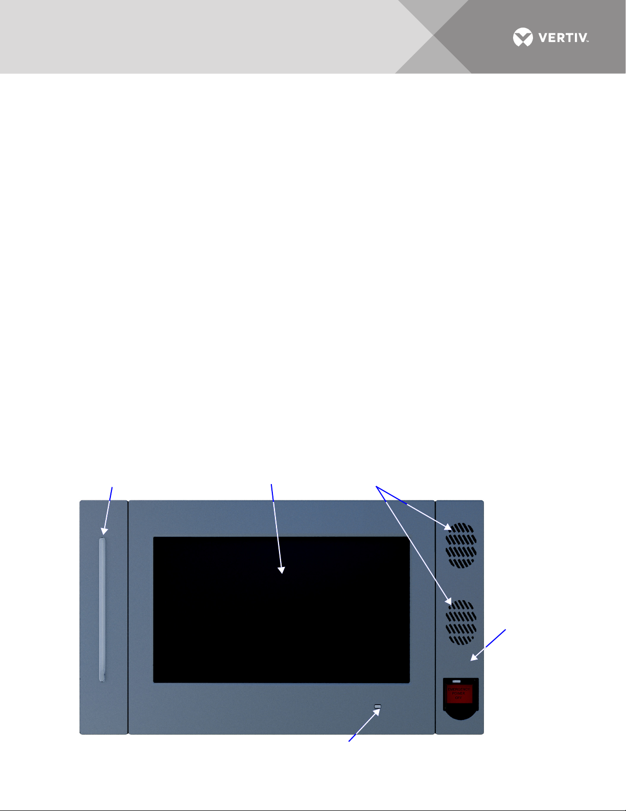
1.0 INTRODUCTION
Speakers (not used)
Touchscreen LCD
EPO Switch
UPS Status LED
UPS Status LED
The Touchscreen Control Panel’s integrated interface simplifies monitoring and managing single or multiple
Liebert UPS modules. The control collects a profusion of information about the health of the modules and
presents it in a standardized format. This simple, dynamic display speeds operator response to changing power
input and demand.
Many of the settings will depend on the UPS type and features. Many settings will be made by Vertiv personnel
when setting up the UPS.
The Touchscreen Control Panel’s interface will display data either graphically or in text. The Status Scroll Bar at
the top of the touchscreen display summarizes system conditions. The bar changes color to indicate status and
includes an icon matched to the status. The Status Gauge displays such details as power demand from the
connected load, input power quality, output and bypass on each phase and battery capacity.
The Touchscreen Control Panel’s mimic display shows the comprehensive system information that the operator
needs:
• Is input power connected?
• Are there any alarms?
• Which breakers are open and which are closed?
• Is the UPS on battery?
• How much battery run time is available?
Checking a particular component is as simple as touching it on the mimic display—Detailed data appears,
allowing the operator to respond.
Visual and audible alarms alert personnel to faults and alarms requiring immediate attention.
Passcodes for each level of access—Operator, Administrator and Service—secure the UPS against unauthorized
changes. Personnel without a passcode can view UPS status, but cannot change any functions or the
appearance of the interface.
Figure 1 Touchscreen Control Panel components
Vertiv™|Liebert® EXL™ S1 Touchscreen Control User Manual | Rev. 1 | 12/2017 | 1
Page 8

2.0 NAVIGATING THROUGH THE TOUCHSCREEN CONTROL PANEL
The Touchscreen Control Panel is active whenever the UPS has input power. The touchscreen LCD on the front
of the UPS permits:
• Logging in to the system—3.1 - Log In to the Touchscreen Control Panel
• Customizing the user interface—2.4 - Customizing the Display
• Checking the status of the UPS and its external batteries, including all measured parameters, events and alarms—4.0 -
VIEWING UPS STATUS and 5.0 - VIEWING UPS COMPONENT STATUS
• Determining when users logged in and out—4.3 - Logs—Events and Log-In Times
• Silencing alarms—3.3.1 - OPERATE Menu—Silence an Alarm
•Turning the UPS On —3.3.2 - OPERATE Menu—Inverter On
• Turning the UPS Off—3.3.3 - OPERATE Menu—Inverter Off
• Resetting faults—3.3.4 - OPERATE Menu—Reset Fault
• Enabling Energy Saving Mode—3.3.6 - OPERATE Menu—Energy Saving Mode Activation
The Touchscreen Control Panel’s display default view is two panes: One-line animated mimic and UNIT STATUS.
The appearance can be changed to multiple panes that show other data. Customizing the appearance is detailed
in 2.4 - Customizing the Display.
2.1 Restrict Physical Access with Barriers or Set Log-In Codes
NOTICE
Risk of unauthorized changes to UPS operational settings. Can cause equipment damage.
Because a UPS such as the Liebert EXL S1 is usually installed in areas that restrict physical access, the Touchscreen
Control Panel does not, by default, require a PIN to change UPS settings and operations.
If physical access cannot be restricted with barriers and identity cards, PIN codes may be set in the Touchscreen Control
Panel to prevent unwanted changes to the Liebert EXL S1.
The Touchscreen Control Panel has four possible access levels—Observer, Operator, Administrator and
Service—each with different levels of authority. The Service level, which permits configuration changes, is the
only level that, by default, requires a PIN.
The default access level for the Touchscreen Control Panel is Administrator. When a PIN is set for the
Administrator, the control panel opens at the Operator level.
To set or change a PIN, refer to 3.1 - Log In to the Touchscreen Control Panel.
Vertiv™|Liebert® EXL™ S1 Touchscreen Control User Manual | Rev. 1 | 12/2017 | 2
Page 9
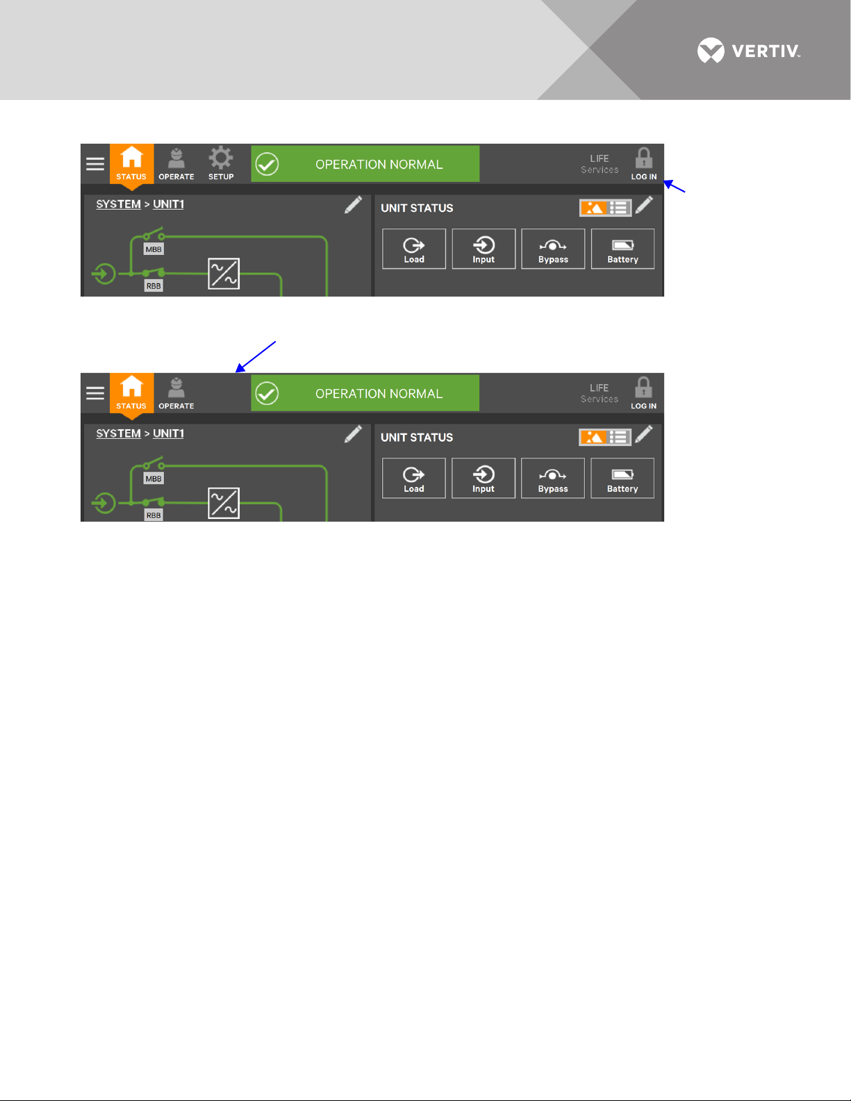
Figure 2 Opening screens
Default opening
screen; no PIN
required;
Administrator
level access for
all with physical
access to UPS.
Default opening screen; PIN required; Note that
the SETUP Function Menu is absent. Operator
level access for all with physical access to UPS.
Vertiv™|Liebert® EXL™ S1 Touchscreen Control User Manual | Rev. 1 | 12/2017 | 3
Page 10
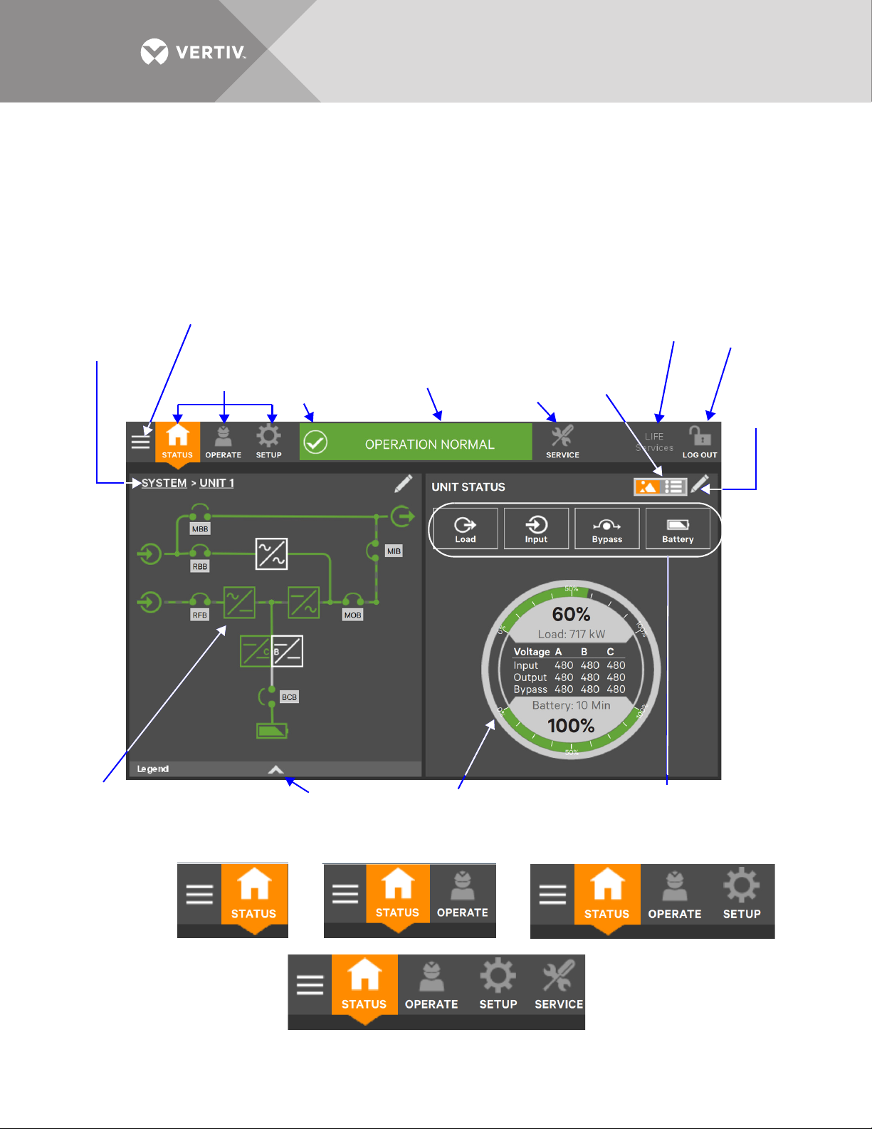
2.2 Touchscreen Control Panel Components
UPS Status Bar
(Scrolls through
status information)
Log In/Out
Icon
Parameter Icons
(Maximum of four visible if
the Status Gauge is showing)
Edit
Interface
Icon
Graphic or
Text View
Interface
Switch
Function Menu
Icons (Varies by
access level)
Context
Menu Icon
Status Gauge
Animated Mimic Display
(Unit 1 mimic displayed.)
Legend Drawer
(See Figure 6)
SERVICE ACCESS LEVEL SCREEN SHOWN
Other access levels will show different function menu icons, but
the rest of the screen will be the same.
Status Bar
Icon
Function Menu Icon
(Service is visible
only when Service
log-in is entered.)
LIFE Services
Menu Icon
System link
(When active,
output shows
system values)
Observer Level Operator Level
Administrator Level
Service Level
The main areas of the Touchscreen Control Panel are shown in Figure 3. The display arrangement and the
information displayed can be changed.
At log-in for all access levels, the Touchscreen Control Panel opens to the STATUS screen in graphic display. The
status of Unit 0 will be shown if the system is a single-unit configuration. In a parallel setup, the STATUS screen shows
the unit where the HMI is installed or the system view. The STATUS screen will show the animated mimic and system
status readings at each log-in level. The appearance will differ only in the function menus displayed (see Figure 4).
Figure 3 Interface overview—STATUS screen; graphic display
Figure 4 Control display by access level—if PIN’s are required
Vertiv™|Liebert® EXL™ S1 Touchscreen Control User Manual | Rev. 1 | 12/2017 | 4
Page 11
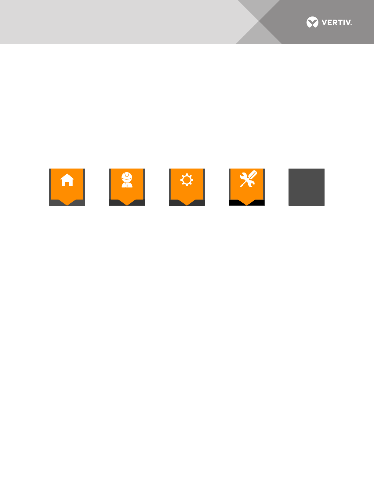
Each Function Menu offers different information and control choices.
STATUS
OPERATE
SETUP
SERVICE
LIFE
Services
Function Menu icons are orange and white when selected, except the LIFE
Services icon; it remains dark gray with green text, if LIVE Services is activated.
If PIN’s are not required, the user will see the STATUS, OPERATE, SETUP and LIFE Services Function Menus.
If PIN’s are required, the user’s access level determines which Function Menu icons are displayed. For example,
logging in as Operator will show the STATUS, OPERATE and LIFE Services Function Menus; logging in as
Administrator will show those menus as well as the SETUP Function Menu (see Figure 4).
• STATUS: Condition of the UPS modules and components and data affecting operation and performance; visible at all access
levels.
• OPERATE: UPS operation controls, such as Inverter On, Inverter Off and Energy Saving Status; visible to Operator,
Administrator and Service
• SETUP: Manage permissions through PIN’s; visible to Administrator and Service
• SERVICE: Input wiring and breaker configuration, parallel status, protocol used and battery charging method; visible only to
Service
• LIFE Services: Information for assistance to enable LIFE customer care. LIFE Services requires a maintenance contract. The
service must be activated with assistance by calling the listed telephone number; visible to all, including Observers.
Vertiv™|Liebert® EXL™ S1 Touchscreen Control User Manual | Rev. 1 | 12/2017 | 5
Page 12
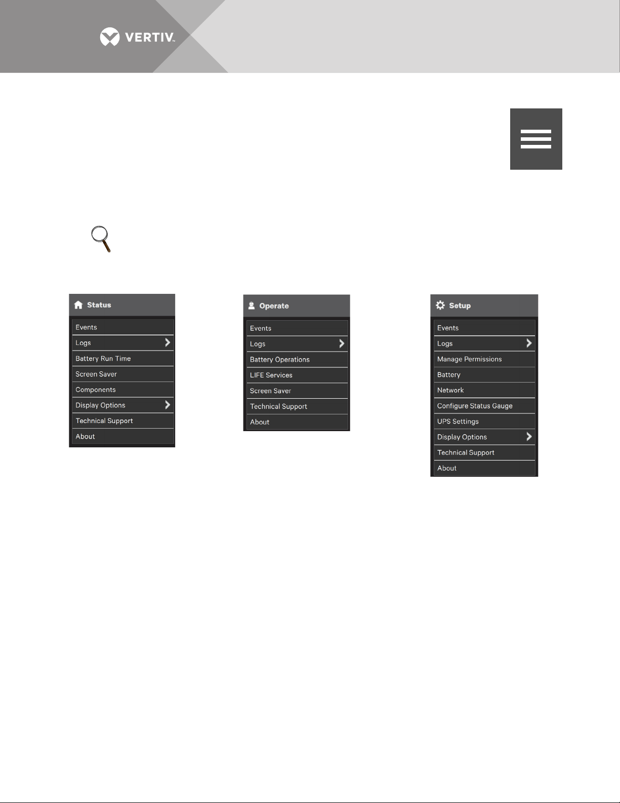
2.2.1 Context Menus
Menu Icon
STATUS Function Menu Selected
OPERATE Function Menu Selected
SETUP Function Menu Selected
(Not shown to Observer or Operator
if PIN’s are required)
The Context Menus, available by touching the Menu icon at the top left corner of the interface,
display information about the UPS and permit changing various settings. The functions possible
through the Context Menus are determined by the user’s access level and on the Function Menu
that is active (see Figure 5).
The items under Display Options on the STATUS Context Menu, for example, differ for each access
level.
Some information available through the Context Menu, such as alarms and run hours, are available through other
areas of the Touchscreen Control Panel.
NOTE
The LIFE Services Function Menu icon has no associated Context Menu. Commands and operations related
to LIFE Services are found on the OPERATE Context Menu.
Figure 5 Context Menus
Context Menu—STATUS
Selecting the STATUS icon and touching the Menu icon reveals a Context Menu that permits performing several
actions or accessing additional information (see Figure 5). Touching a Context Menu item will reveal data or
expand the menu to show additional options.
Vertiv™|Liebert® EXL™ S1 Touchscreen Control User Manual | Rev. 1 | 12/2017 | 6
Page 13

The Context Menu for the STATUS icon shows these items:
• Events: Date and time of occurrence, type of event, Event ID, component affected and description. Events can be sorted by
type, event ID, component, description. The touchscreen also permits filtering events by severity (Status, Alarm or Fault); or
by component (bypass, monitoring process or the module where the event occurred).
• Logs: UPS Event Log and Audit Log
• UPS Event Log shows date and time of event occurrence, type of event, Event ID, status. component affected and
description; same options for all access levels. The Event Log can be exported as a CSV file for record-keeping,
analysis and similar uses.
• Audit Log shows date and time that users with UPS control access logged into and out of the system. The Audit log can
be exported as an XML or CS‘V file for record-keeping, analysis and similar uses.
• Battery Run Time: Battery Cycle Monitor with duration and count
• Screen Saver: Display Sleep Mode notification (immediate entry into screen saver); screen goes dark and user is logged off;
touching the screen reactivates the interface.
• Total Run Hours: Component and hours it has operated; touching a component displays details in the right panel.
• Components: Component status, name and details
• Display Options (changes affect the view for all viewers)
• Customize Layout: Change panel content and layout (see 2.4 - Customizing the Display)
• Display Properties: Language, back-light timer, alarm timeout, auto-log-out timer, display brightness, status indicator
brightness and touchscreen calibration (see 2.4 - Customizing the Display)
• Date & Time: Drop-down lists for time zone, date, local time and UTC time (Coordinated Universal Time) (see 2.4 -
Customizing the Display)
• Formats: Drop-down lists for date and time format and measurement system (metric or imperial) (see 2.4 -
Customizing the Display)
• Custom Labels: Rename settings, serial ports and network interfaces to ease troubleshooting and refine data. (The
default name of COM1 may be adequate, but renaming it with the connected device may ease determining the cause
of an alarm).
• Technical Support: Manufacturer’s support: Web site, e-mail address and telephone numbers
• About: Information about the UPS and its software and firmware; UPS model, rating, configured capacity, model number and
serial number.
Context Menu—OPERATE
Selecting the OPERATE icon and touching the Menu icon reveals a Context Menu that permits performing
several actions or accessing additional information (see Figure 5). Touching a Context Menu item will reveal
data or expand the menu to show additional options.
The Context Menu for the OPERATE icon shows these items:
• Events: Date and time of occurrence, type of event, Event ID, component affected and description. Events can be sorted by
type, event ID, component, description. The touchscreen also permits filtering events by severity (Status, Alarm or Fault); or
by component (bypass, monitoring process or the module where the event occurred).
• Logs: UPS Event Log and Audit Log
• UPS Event Log shows date and time of event occurrence, type of event, Event ID, status. component affected and
description; same options for all access levels. The Event Log can be exported as a CSV file for record-keeping,
analysis and similar uses.
• Audit Log shows date and time that users with UPS control access logged into and out of the system. The Audit log can
be exported as an XML or CS‘V file for record-keeping, analysis and similar uses.
• Battery Operations: Battery testing and charging; automatic, manual and calibration battery testing and battery equalize
charging.
• LIFE Services: Customer care assistance contact and reporting center; must be activated with assistance by calling the
listed telephone number;
• Screen Saver: Display Sleep Mode notification (immediate entry into screen saver); screen goes dark and user is logged off;
interface reactivated by touching the screen; same options for all access levels
• Technical Support: Manufacturer’s support: Web site, e-mail address and telephone numbers
• About: Information about the UPS and its software and firmware; UPS model, rating, configured capacity, model number and
serial number
Vertiv™|Liebert® EXL™ S1 Touchscreen Control User Manual | Rev. 1 | 12/2017 | 7
Page 14

Context Menu—SETUP
Selecting the SETUP icon and touching the Menu icon reveals a Context Menu that permits
performing several actions or accessing additional information (see Figure 5). Touching a Context
Menu item will reveal data or expand the menu to show additional options.
The Context Menu for the SETUP icon shows these items:
• Events: Date and time of occurrence, type of event, Event ID, component affected and description. Events
can be sorted by type, event ID, component, description. The touchscreen also permits filtering events by
severity (Status, Alarm or Fault); or by component (bypass, monitoring process or the module where the event occurred).
• Logs: UPS Event Log and Audit Log
• UPS Event Log shows date and time of event occurrence, type of event, Event ID, status. component affected and
description; same options for all access levels. The Event Log can be exported as a CSV file for record-keeping,
analysis and similar uses.
• Audit Log shows date and time that users with UPS control access logged into and out of the system. The Audit log can
be exported as an XML or CS‘V file for record-keeping, analysis and similar uses.
• Manage Permissions: Change or require PIN for users of Administrators or Operators.
• Network: Modify communication settings.
• Configure Status Gauge: Modify information shown on Status Gauge.
• UPS Settings: Enable or disable audible alarm and modify energy saving configuration (Eco Mode or Intelligent Parallel).
• Display Options (Changes affect view for all access levels)
• Customize Layout: Change panel content and layout (see 2.4 - Customizing the Display).
• Display Properties: Language, back-light timer, alarm timeout, auto-log-out timer, display brightness, status indicator
brightness and touchscreen calibration (see 2.4 - Customizing the Display).
• Date & Time: Drop-down lists for time zone, date, local time and UTC time (Coordinated Universal Time) (see 2.4 -
Customizing the Display).
• Formats: Drop-down lists for date and time format and measurement system (metric or imperial) (see 2.4 -
Customizing the Display).
• Custom Labels: Rename settings, serial ports and network interfaces to ease troubleshooting and refine data. (The
default name of COM1 may be adequate, but renaming it with the connected device may ease determining the cause
of an alarm).
• Technical Support: Manufacturer’s support: Web site, e-mail address and telephone numbers.
• About: Information about the UPS and its software and firmware; UPS model, rating, configured capacity, model number and
serial number.
2.3 SYSTEM PANE—Mimic Display Components
The animated mimic display, the default view for the control, shows each configured major component of the
UPS system, for both single-module and multi-module systems. The mimic display is the same for all access
levels. The power path is shown by animated lines; moving dashes show the active power path. Touching a
component (except a breaker) brings up details about the component’s status. Breakers are shown as open or
closed (see Figure 6), but they are not interactive.
Components in the mimic display signify their operational status by their color, green, amber or red. Tables 9
through 11 describe the various states of the indicators.
The animated mimic display can be changed to any of five other views: Status, Alarms, Run Hours, Event Log and
Battery Cycle Monitor Summary (see 2.4 - Customizing the Display).
Vertiv™|Liebert® EXL™ S1 Touchscreen Control User Manual | Rev. 1 | 12/2017 | 8
Page 15
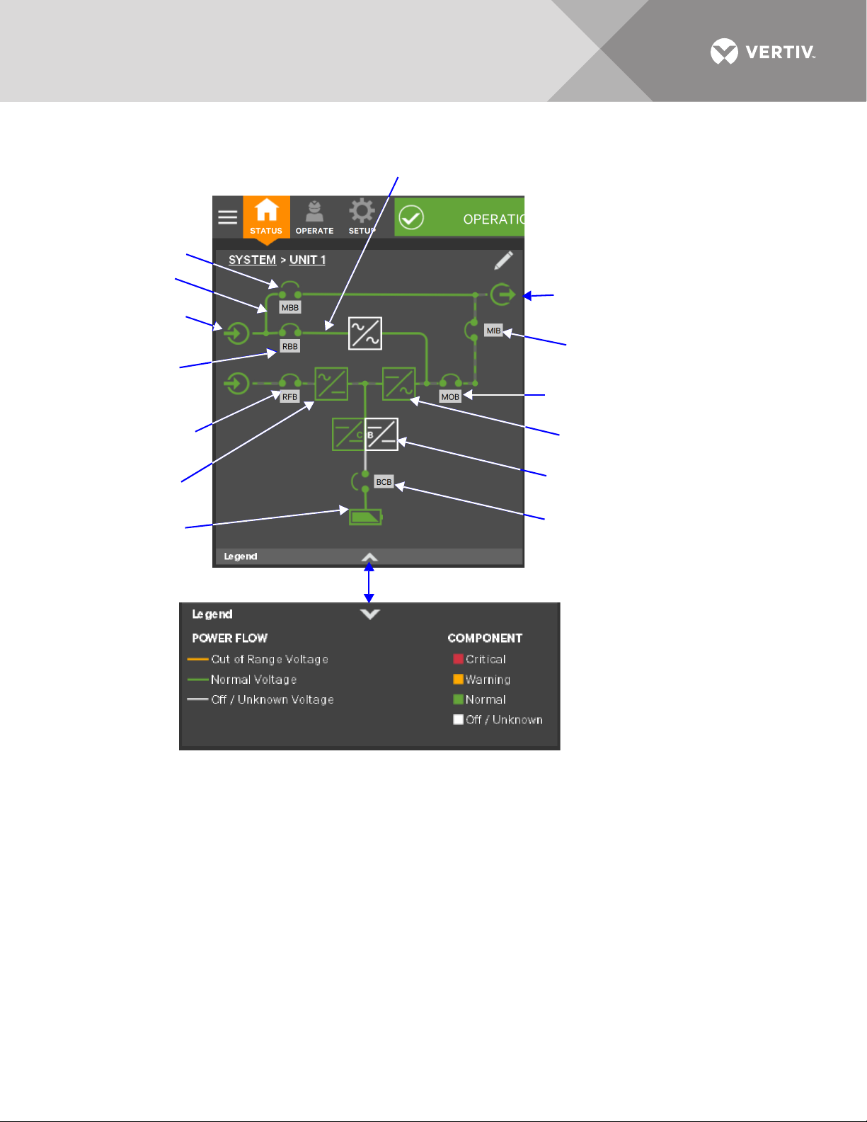
Figure 6 Mimic display, normal operation, default view/unit view
Output Power
(interactive)
Input Power
(interactive)
Internal Static Bypass
(interactive)
DC Source
(Batteries)
(interactive)
Rectifier Feed
Breaker
Touching the arrowhead reveals the legend.
Maintenance
Bypass Breaker
Breakers in a system are determined
during setup and can be installed or
removed by Service.
Breakers shown are:
BCB: Battery Isolation Switch
BIB/RBB: Bypass Isolator
RFB: Input Isolator
MBB: Maintenance Bypass Isolator
MIB: Output Isolator
Inverter (interactive)
Charger/Booster
(interactive)
Battery Cabinet Breaker
Remote Back-Feed
Breaker; may be
replaced with optional
Back-Feed Disconnect
Maintenance Isolation Breaker
Module Output Breaker
Rectifier
(interactive)
Maintenance
Bypass Path
Vertiv™|Liebert® EXL™ S1 Touchscreen Control User Manual | Rev. 1 | 12/2017 | 9
Page 16
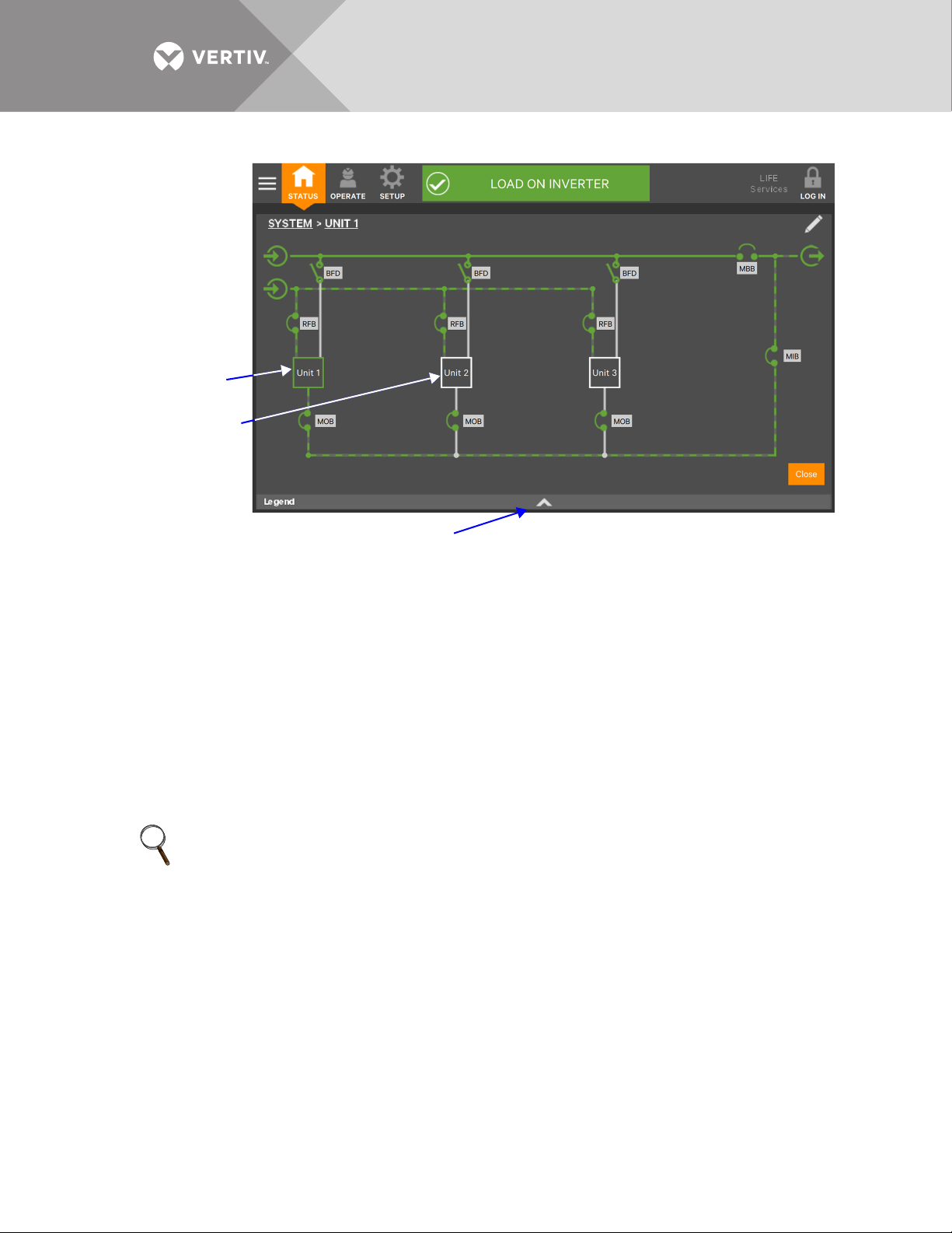
Figure 7 Mimic display, normal operation, system view
Touching the arrowhead reveals the legend.
Green outline indicates
communication is active
and operating normally.
White outline indicates no
communication occurring.
Yellow indicates the unit is
communicating but in a
warning state.
Red indicates the unit is
communicating but in a
fault state.
System view is obtained
by touching SYSTEM in
the default mimic view.
To return to default view,
touch Unit 1 or Close
(bottom right).
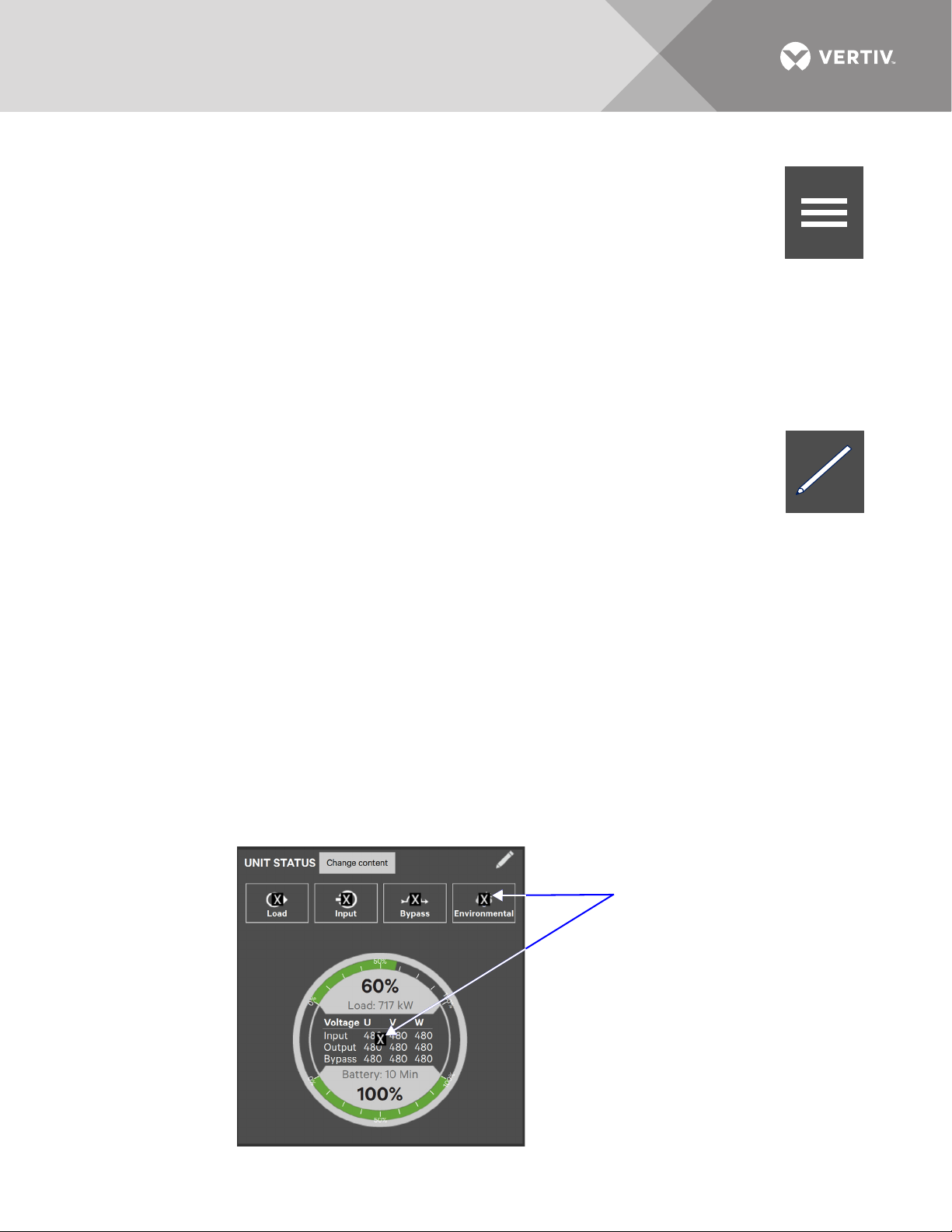
2.3.1 UNIT STATUS Pane Components
The UNIT STATUS pane is identical for all PIN access levels (see Figure 8), if PIN’s are required. Observers will
not have the edit icon (pencil). In the default graphic view, the UNIT STATUS pane shows:
• Status Gauge—Connected load shown in kW and as a percentage of capacity; input, output and bypass voltage for each
phase (default data may be changed; see 4.1 - Viewing UPS Data with the Status Gauge).
• Load Detail Icon
• Input Detail Icon
• Bypass Detail Icon
• Battery Detail Icon
The detail icon for Environmental may be added to the UNIT STATUS pane if there is space.
Touching any of the detail icons reveals additional data about that selection in the opposite pane. The data pane
may be closed by touching the Close button or by touching any detail icon. The read-only information is
available to all access levels (see Figures 9 through 13).
NOTE
If the Status Gauge is showing, no more than four detail icons will be visible. Removing the Status Gauge permits
showing all five detail icons. The view may be customized to show fewer than four.
Vertiv™|Liebert® EXL™ S1 Touchscreen Control User Manual | Rev. 1 | 12/2017 | 10
Page 17
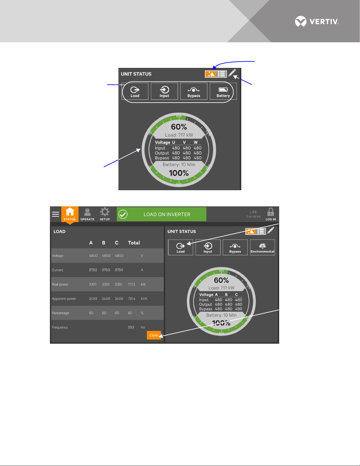
Figure 8 UNIT STATUS pane components—Graphic display
Status Gauge
Detail Icons for Input,
Battery, Bypass and
Load (Touch an icon
to see details about
the linked
component [see
Figure 9].)
No more than four
detail icons will be
visible when the
Status Gauge is
shown.
Edit icon
Touch this icon to switch
to Text Display.
Touch Close or the
Load icon to close
the Load detail pane
and return to the
animated mimic.
Load icon touched
to show data in
the left pane.
Figure 9 UNIT STATUS pane—Load details; graphic display
Vertiv™|Liebert® EXL™ S1 Touchscreen Control User Manual | Rev. 1 | 12/2017 | 11
Page 18
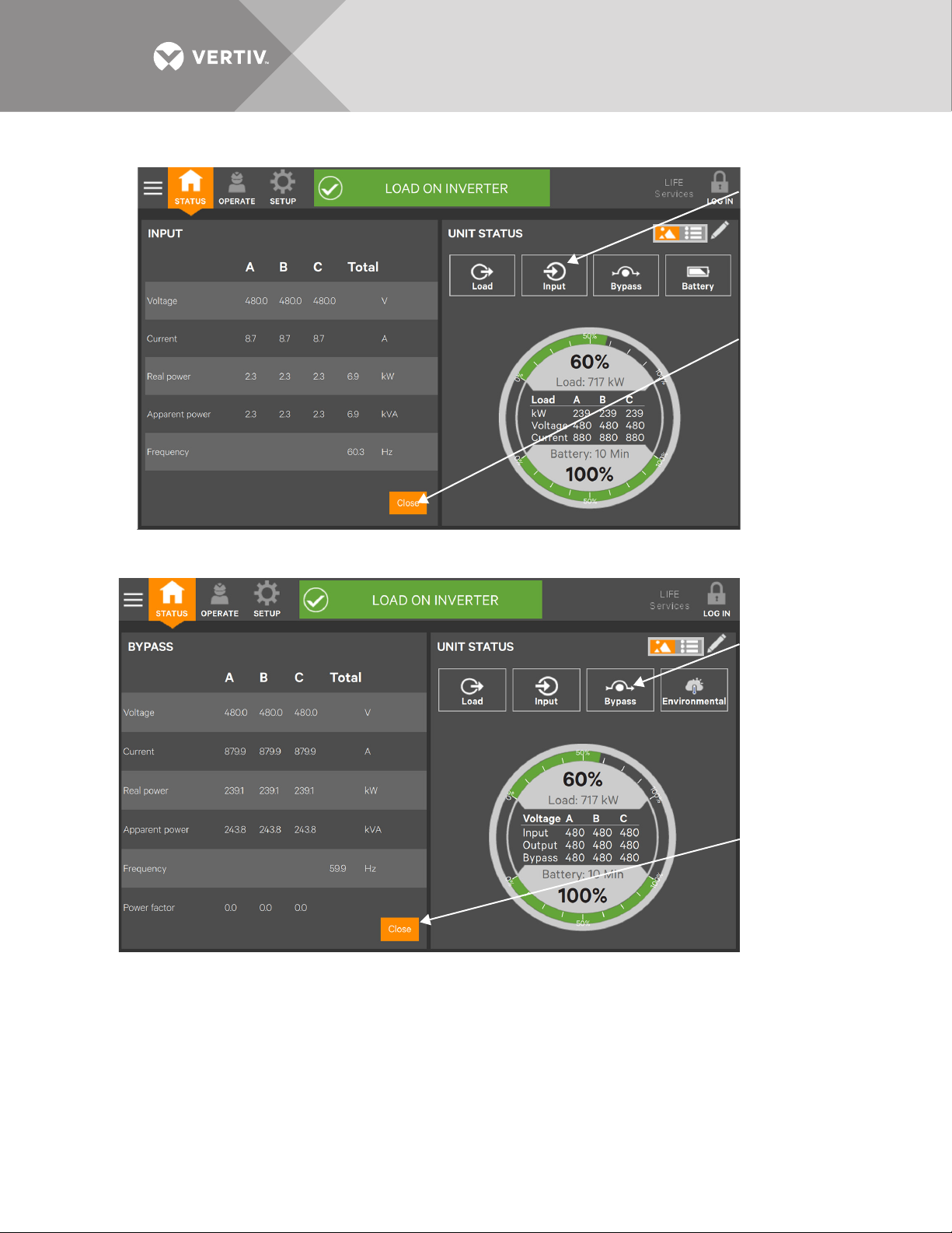
Figure 10 UNIT STATUS pane—Input details; graphic display
Input detail icon
touched to show
data in the left pane.
Touch Close or the
Input icon to close
the Input detail pane
and return to the
animated mimic.
Bypass detail
icon touched to
show data in the
left pane.
Touch Close or the
Bypass icon to close
the Bypass detail
pane and return to
the animated mimic.
Figure 11 UNIT STATUS pane—Bypass details; graphic display
Vertiv™|Liebert® EXL™ S1 Touchscreen Control User Manual | Rev. 1 | 12/2017 | 12
Page 19
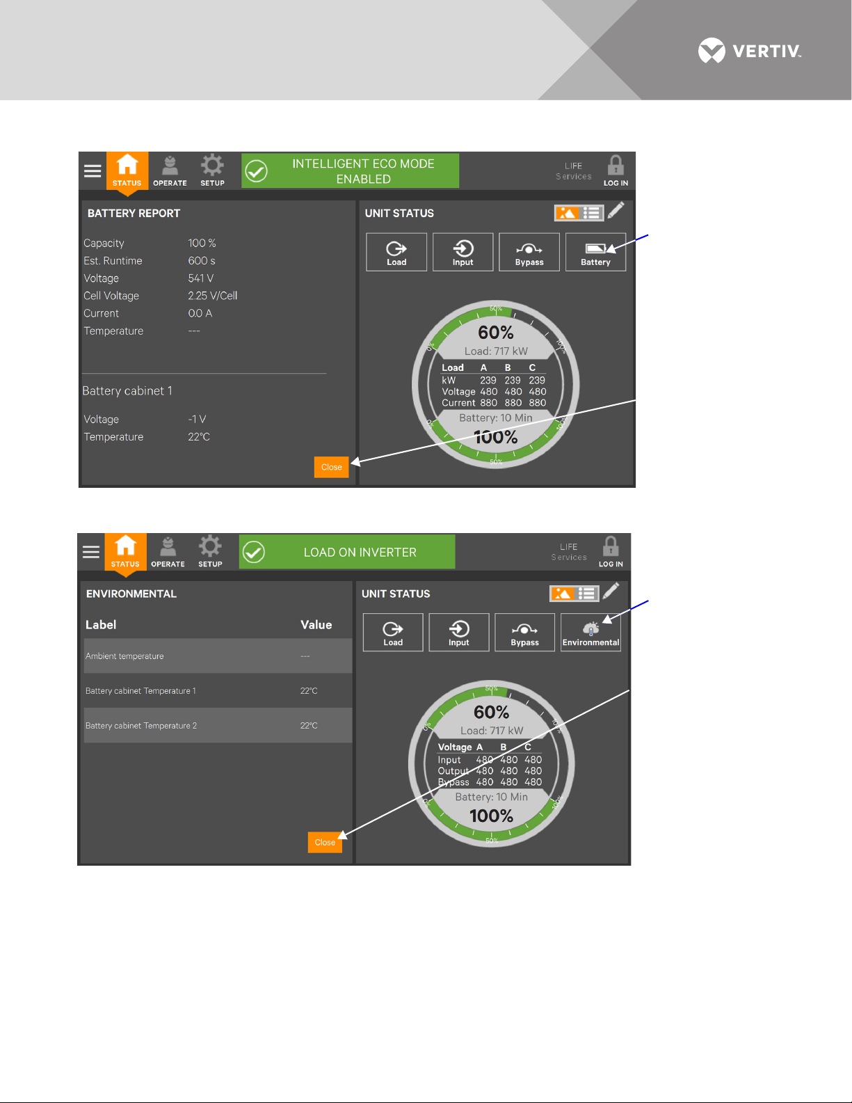
Figure 12 UNIT STATUS pane—Battery and cabinet details; graphic display
Battery detail icon
touched to show
data in the left pane.
Touch Close or the
Battery icon to close
the Battery detail
pane and return to
the animated mimic.
Environmental detail
icon touched to show
data in the left pane.
Touch Close or the
Environmental icon to
close the
Environmental detail
pane and return to the
animated mimic.
Figure 13 UNIT STATUS pane—Environmental details; graphic display
Vertiv™|Liebert® EXL™ S1 Touchscreen Control User Manual | Rev. 1 | 12/2017 | 13
Page 20
2.4 Customizing the Display
STATUS
Context Menu
STATUS Icon
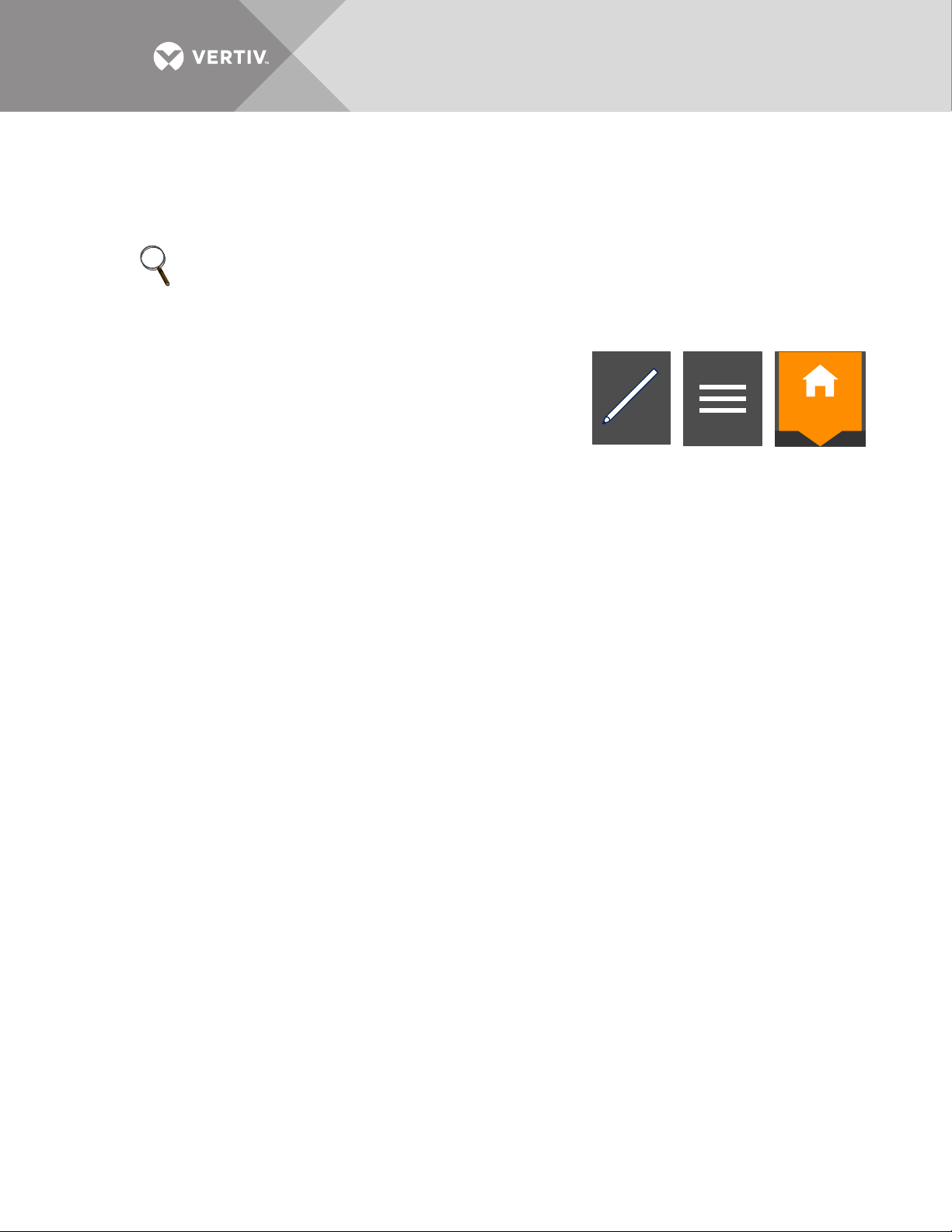
Edit Icon
The Touchscreen Control Panel’s default appearance will be adequate for most installations, but the Status
panels can be altered to show additional or different data. The layout selected will be applied to all users. If PIN’s
have been activated, layouts may be created or altered with Operator, Administrator or Service Access.
NOTE
The original configuration, Default View 1, cannot be deleted, though it can be changed. Editing it will create a
modified view with the new settings. The Default View 1 can be altered with the edit icon (pencil) in the display
(see 2.4.2 - Using the Edit Icon to Customize Layout).
To customize the display’s appearance:
1. Log in to the Touchscreen Control Panel, if a PIN is required.
2. From the STATUS view, touch the Context Menu icon in the top left
corner.
3. Select Display Options > Customize Layout. (The right pane details how
to edit or create a view; see Figure 14.)
Edit a View
4. Touch a view to highlight it.
5. Touch Edit to change that view.
6. Alter the layout—Add or remove a panel or associate different options with a panel.
7. Touch the
Create a View
8. Touch the New button to create a view.
Save button to keep your changes or touch Cancel to exit without saving.
Vertiv™|Liebert® EXL™ S1 Touchscreen Control User Manual | Rev. 1 | 12/2017 | 14
Page 21
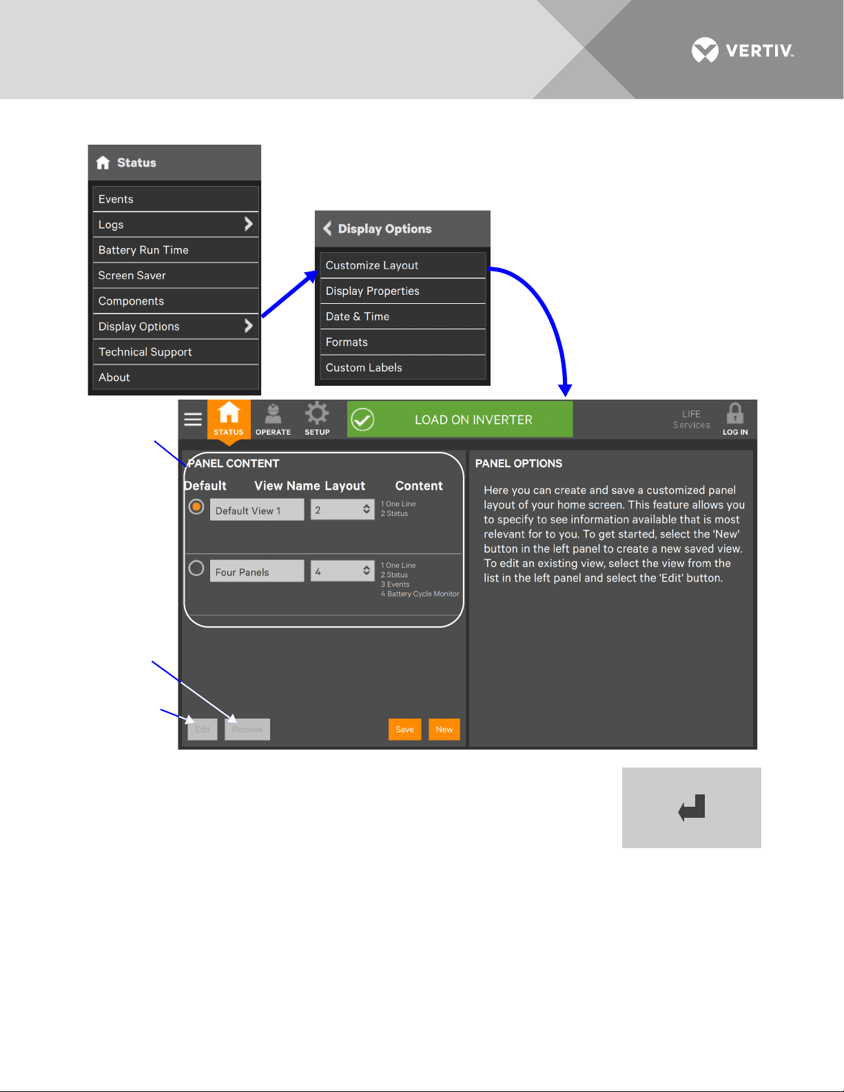
Figure 14 Customize the display
Edit Button
Remove View
Button
Panel shows
view name,
layout and
content.
Enter Key
9. Either accept the generated name (New View) or touch the view’s name to rename it using
the on-screen keyboard (maximum length is 15 characters including spaces). Touch the
Enter key on the on-screen keyboard after entering the new name.
10. Select the number of panels in the new or edited view from the drop-down list under the
Layout heading. The maximum is four.
11. Choose the data to be displayed in each pane by touching a choice in the PANEL OPTIONS
pane and then touching the appropriate panel. Repeat for each panel.
12. Touch the
Save button to keep the changes or touch the Cancel button to exit the screen
without saving.
Vertiv™|Liebert® EXL™ S1 Touchscreen Control User Manual | Rev. 1 | 12/2017 | 15
Page 22

Figure 15 Set number of panes and choose data
Choose the
number of
panels from
the drop-down
list.
Follow the instructions in PANEL OPTIONS
(see Figure 15) to choose the data to be
displayed. The Save button is inactive until
the setup requirements are complete.
To choose an existing layout, navigate to the PANEL CONTENT screen and touch the radio button beside the
layout, then touch the STATUS Function Menu.
Vertiv™|Liebert® EXL™ S1 Touchscreen Control User Manual | Rev. 1 | 12/2017 | 16
13. Touch the Save button.
14. When the window returns to two screens—PANEL CONTENT and PANEL OPTIONS—touch the radio button beside the
new view to activate it (this puts a dot in the circle).
15. Touch
Save.
16. Touch the STATUS Menu icon to see the new appearance.
Page 23
2.4.1 Remove a Layout
Context
Menu Icon
Edit Icon
Touch the X on a parameter
or the X on the Status Gauge
to remove it from the view.
To delete a layout:
1. Log in with Administrator or Service access, if a PIN is required.
2. From the STATUS view, touch the Context Menu icon in the top left corner.
3. Select Display Options > Customize Layout. (The right pane details how to edit or create a view; see
Figure 14.)
4. Touch a view to highlight it.
Edit a View
5. Touch Edit to change the highlighted view.
6. Make the changes.
7. To uch Save to keep the changes
Remove a View
8. Touch
Remove to delete the highlighted view.
2.4.2 Using the Edit Icon to Customize Layout
The Touchscreen Control Panel layout can also be changed with the Edit icons on the screen. The
Edit icon can be used to add or remove panels, resize panels, rearrange panels and change
monitored parameters.
To use the Edit icon:
1. Touch the Edit icon on the panel to be edited and hold it until a Change content button appears on the panel
(about 1 second).
Change Panel
2. Touch an icon to choose the data to be displayed in the panel (see Figure 17); choices are:
One-Line Event Log
Status Battery Cycle Monitor
Events Energy Log
Run Hours Battery Log
Service History Battery Time Remaining
Change UNIT STATUS Panel Content (see Figure 16)
3. To change the UNIT STATUS panel’s content:
a. Touch the Edit icon on the UNIT STATUS panel and hold it until the Change
parameters.
b. Touch the X on the parameter to be removed from the panel.
Figure 16 Edit UNIT STATUS panel
content button and X’s appear on the
Vertiv™|Liebert® EXL™ S1 Touchscreen Control User Manual | Rev. 1 | 12/2017 | 17
Page 24

The Add Parameter icon (+) will appear in the panel if another parameter can be added. The number
+
Add Parameter
Icon
Touch the Change content
button to display the choices.
of parameters that may be shown is based on whether the Status Gauge is showing.
c. Touching the Add Parameter icon brings up a window to add parameters not already shown on
the UNIT STATUS panel.
d. Touch a parameter’s icon to add it to the UNIT STATUS panel.
Resize or Remove a Panel (see Figure 18)
4. Touch and hold the Edit icon again while the
5. Release the icon. Resize handles will appear around the panel and a large
right corner.
6. Pull on a handle to resize the panel, or
7. Touch the large
Rearrange Panels (see Figure 18)
8. With the resize handles and
Exit Edit Mode
9. Edit Mode will deactivate after some changes. If all changes have been made and Edit Mode is active, touch the panel’s
header area to exit Edit Mode.
Figure 17 Change panel content
X to delete the panel.
X’s visible, touch the circle in the center of the panel and drag the panel to its new position.
Change content button is displayed.
X will appear at the top
Vertiv™|Liebert® EXL™ S1 Touchscreen Control User Manual | Rev. 1 | 12/2017 | 18
Page 25

Figure 18 Resize, remove or rearrange a panel
Pull a handle to
resize the
panel.
Touch the X to remove
the panel from the view.
Use this large circle to drag
the panel to a new position
in the view.
+
Add Parameter
Icon
2.4.3 Edit the UNIT STATUS Panel with the Edit Icon
The UNIT STATUS panel may be changed to add or remove data. The panel has four default parameters. Any or
all can be deleted or replaced using the Edit icon.
Possible parameters for the UNIT STATUS panel are:
•Input
•Bypass
• Battery
• Environmental
•Load
NOTE
Changes made to the UNIT STATUS panel will be applied to all views using the panel for all viewers.
NOTE
If the Status Gauge is showing, no more than four detail icons will be visible. Removing the Status Gauge permits
showing all five detail icons. The view may be customized to show fewer than four.
To edit the UNIT STATUS panel:
1. Activate Edit Mode by touching and holding the Edit icon on the UNIT STATUS panel.
2. Touch the large X beside a parameter icon or the X on the Status Gauge to delete the feature or touch
3. Touch the header area or a non-interactive area of the panel to deactivate edit mode.
the + icon at the right side of the panel to add a parameter icon.
Vertiv™|Liebert® EXL™ S1 Touchscreen Control User Manual | Rev. 1 | 12/2017 | 19
Page 26

Figure 19 Edit UNIT STATUS panel
Touch an X to remove the associated
parameter from the panel.
Touch the + icon to add a parameter to
the panel; a maximum of four icons are
possible if the Status Gauge is showing.
The Add Parameter box opens showing
parameters that may be added.
2.4.4 Setting DISPLAY PROPERTIES
The Context Menu for either OPERATE or SETUP permits determining how data is displayed. The DISPLAY
PROPERTIES menu is available to any user, including Observers. However, the items that may be altered differs
with each access level, if PIN’s are required.
Table 1 Available display properties by access level if PIN’s are required
Display Property
Language ✔✔ ✔ ✔
Theme ✔✔ ✔ ✔
Backlight Off Timer X ✔✔✔
Alarm Window Timeout X ✔✔✔
Auto-Logout Timer X X ✔✔
Display Brightness ✔✔ ✔ ✔
Status Indicator Brightness X X ✔✔
Calibrate Touch Screen X X ✔✔
Observer Operator Administrator Service
Access Level
Language: The default setting is English; other choices are Chinese, Spanish and Canadian French.
Theme: The default setting is Dark_Gray_9; other choices are Blue_9 and Light_Gray_9. Themes change not only
the background, but also the color of some menus.
Backlight Off Timer: The default setting is Off After 5 Minutes; other choices are Off After 10 Minutes, 20
minutes, 30 minutes, 45 minutes, 60 minutes and Never.
Alarm Window Timeout: The default setting is Never. It may be changed in one-day increments from one day to
14 days.
Auto-Logout Timer: The default setting is Logout After 5 Minutes. It may be changed in one-minute increments
from one minute to 5 minutes.
Display Brightness: The default setting is 80 percent, but the brightness may be changed in increments of 20
percent from the low of 20 percent to 100 percent.
Status Indicator Brightness: The default setting is 80 percent; brightness may be changed in increments of 20
percent from the low of 20 percent to 100 percent.
Vertiv™|Liebert® EXL™ S1 Touchscreen Control User Manual | Rev. 1 | 12/2017 | 20
Page 27

Calibrate Touch Screen: No default value; instructions must be followed to calibrate the touchscreen. A
These values are entered when the
Touchscreen Control Panel is
configured. Changing them requires
Administrator or Service access.
UTC is a world standard and cannot
be changed.
notification warns that performing a calibration on a properly functioning touchscreen could cause the
touchscreen to fail. The notification offers a choice of going ahead with the calibration or canceling it.
2.4.5 Setting Date, Time and Time Zone
The date, time and time zone are set when the Touchscreen Control Panel is configured.
Changing the date, the time and the time zone may be done through the Context Menu on either the STATUS or
SETUP page (STATUS>Display Options>Date & Time or SETUP>Display Options>Date & Time). If PIN’s are
required, changing the date, time or time zone requires Administrator or Service access. These settings can be
viewed, but cannot be changed, by Observers and Operators.
The format of the date or time may be changed through the Context Menu on either the STATUS or SETUP
page (STATUS>Display Options>Date & Time or SETUP>Display Options>Date & Time) (refer to 2.5 - Changing
Date, Time and Measurement Formats).
NOTE
The UTC Time is a world standard that the Touchscreen Control Panel displays. It cannot be changed.
NOTE
If LIFE Services is enabled, neither the date nor the time can be changed.
Figure 20 Date and time settings
Changing the Time Zone
The time zone is set when the Touchscreen Control Panel is configured (the default is America/New York). The drop-
down menu permits selecting any time zone on the globe, as well choosing one-hour increments before and
after UTC. To change the time zone:
1. Log in with either Administrator or Service access.
2. Navigate to STATUS>Display Options>Date & Time or to SETUP>Display Options>Date & Time.
3. Touch the
4. Scroll to the appropriate time zone and touch it.
5. Make any other changes on the DATE & TIME page.
6. Touch the
Vertiv™|Liebert® EXL™ S1 Touchscreen Control User Manual | Rev. 1 | 12/2017 | 21
Time Zone box or either arrow on the drop-down menu.
Save button to make the changes or touch Cancel to exit without saving the changes.
Page 28

Figure 21 Time Zone drop-down menu
Touch the Time Zone box ...
... or either arrow to
display the choices.
Scroll through the list
and choose the
appropriate time zone.
Graphic
Date
Display
Touching
this icon ...
reveals the
text display
of the date.
Changing the Date
The date is set when the Touchscreen Control Panel is configured. The default format is month/day/year with
single numerals for months from January through September and for days 1 through 9. Changing how the date is
shown requires using the Formats page found on the Context Menu on either the STATUS or SETUP menu
(refer to 2.5 - Changing Date, Time and Measurement Formats).
To change the date:
1. Log in with either Administrator or Service access, if passwords are required.
2. Navigate to STATUS>Display Options>Date & Time or to SETUP>Display Options>Date & Time.
3. Touch either the
4. Scroll to the correct month and touch the correct day.
5. Make any other changes on the DATE & TIME page.
6. Touch the
Date box or the grid beside it. Either will display a calendar for the month.
Save button to make the changes or touch Cancel to exit without saving the changes.
Figure 22 Change the date
NOTE
Touching the Graphic/Display icon permits changing the date by scrolling though months, days and years.
Vertiv™|Liebert® EXL™ S1 Touchscreen Control User Manual | Rev. 1 | 12/2017 | 22
Page 29

Changing the Time
Touching a numeral or an arrow and
releasing it will increase or decrease the
associated numeral by one. Holding a
numeral or an arrow will scroll continuously.
The AM/PM choice
will not be shown if
the 24-hour clock
format is active.
The time is set when the Touchscreen Control Panel is configured The default format is h:mm AP (hour:minute
AM/PM) with one numeral for hours less than 10 (for example, 1:09 for nine minutes after 1 a.m. and 13:09 for nine
minutes after 1 p.m.). Changing how the time is displayed requires using the Formats page found on the Context
Menu of either the STATUS or the SETUP menu (refer to 2.5 - Changing Date, Time and Measurement Formats).
To change the time:
1. Log in with either Administrator or Service access.
2. Navigate to STATUS>Display Options>Date & Time or to SETUP>Display Options>Date & Time.
3. Touch the
4. Touch the hours, minutes or seconds to be changed or touch the associated Up or Down arrow.
Local Time box or the clock icon beside it. Either will display a digital version of the time.
NOTE
Touching a numeral or the Up arrow and releasing it will increase the numeral by one. Touching the Down arrow
and releasing it decreases the number by one.
Holding a numeral or arrow will scroll continuously. Holding a numeral will scroll Up, increasing the numeral.
Holding an arrow will scroll in the direction the arrow points.
5. When the correct time is shown, touch OK to save the change or touch Cancel to exit without saving.
NOTE
An AM/PM choice will be shown if that format is active. The AM/PM choice will not be shown for the 24-hour
clock format.
6. Make any other changes on the DATE & TIME page.
7. To uch
OK to save the changes or touch Cancel to exit without saving.
Figure 23 Change the time
2.5 Changing Date, Time and Measurement Formats
The Touchscreen Control Panel has these default settings:
• Date: M/d/yyyy
• Time: h/mm (either AM/PM or am/pm)
•Measurement System: Metric
These formats may be changed by any user, including an Observer, by going to Status>Display Options>Formats;
choose the format or measurement system and touch Save.
Vertiv™|Liebert® EXL™ S1 Touchscreen Control User Manual | Rev. 1 | 12/2017 | 23
Page 30

2.5.1 Change the Date Format
Date Format Choices
(scrolling reveals
additional formats)
Time Format Choices
Measurement
Format Choices
Touch inside this box to change the format.
Enter Key
To change the way the date is displayed, touch inside the box containing the date format and choose the format
from the choices shown in Figure 24.
2.5.2 Change the Time Format
To change the way the time is displayed, touch inside the box containing the time format and choose the format
from the choices shown in Figure 24.
2.5.3 Change the Measurement System
To change the way measured values, such as heat, kW and voltage, are displayed, touch inside the box
containing the Measurement System and choose either Imperial or Metric as shown in Figure 24.
Figure 24 Date/Time format and Measurement System choices
2.6 Create or Modify Custom Labels
The CUSTOM LABELS page permits renaming settings, serial ports and network interfaces. New names may be
entered for these to suit local preferences and to ease troubleshooting and refine data. (The default name of
COM1 may be adequate, but renaming it with the connected device may ease determining the cause of an
alarm).
Custom labels may be created or modified by any user, including Observers. The labels are universal and will be
displayed for all users.
To create or modify a custom label:
1. Go to STATUS>Display Options>Custom Labels.
2. Choose the label group to change.
NOTE
Changing a particular Setting may require scrolling (see Figure 25 and Table 2.
3. Touch inside the Custom Label box beside the setting to be labeled.
4. Use the on-screen keyboard to enter the label name.
5. Touch the Enter key.
6. Touch Save to make the change or touch
Vertiv™|Liebert® EXL™ S1 Touchscreen Control User Manual | Rev. 1 | 12/2017 | 24
Cancel to exit without saving.
Page 31

Figure 25 CUSTOM LABELS page
Touch any of
these headings
to create or
modify a label
Table 2 Additional custom label choices for Settings
BackFeed Disconnect Bypass input breaker BIB1Installed
BIB1Open BIB2Installed BIB2Open
BIB3Installed BIB3Open BIB4Installed
BIB4Open BIB5Installed BIB5Open
BIB6Installed BIB6Open BIB7Installed
BIB7Open BIB8Installed BIB8Open
BIB9Installed BIB9Open Backlight Off Timer
Battery Type Bypass Bypass Kva Rating
BypassInputFailure CB1 - Rectifier input breaker CB2 - Inverter output breaker
CB3-Internal bypass breaker Cell Number Check TS Calibration
Country DNS Server Date
Date Format Disconnect Temperature Limit Display Brightness
Display Touch Beep Energy Savings Configuration Equalize Charge Duration
Equalize Charge Voltage Font Name Font Size
Getting Started Visible IOB-Inverter output breaker Inactivity Timer
Kva Per Module Kva Rating LBB - Load bank breaker
Language LifeEnabled Local Contact
Local Life Contact Local Life Service Name Local Service Name
Local Time Location Id MBB - Maintenance bypass breaker
MBBInstalled MBBOpen MBD - Module battery disconnect
MIB-Maintenance isolation breaker MIBInstalled MIBOpen
MOB - Module Output Breaker MainsFailure Manufacturer
Measurement System Minimum Cell Voltage Model
Model Number Model Type Module Number
Monitoring Contact Network Time Protocol Nominal Cell Voltage
Vertiv™|Liebert® EXL™ S1 Touchscreen Control User Manual | Rev. 1 | 12/2017 | 25
Page 32

Table 2 Additional custom label choices for Settings (continued)
Network Interfaces - Custom Labels
Nominal Frequency Nominal Voltage Operator PIN
Q12 - Input transformer isolator Q21 - Bypass transformer isolator Q22 - Bypass isolator
Q33 - Static switch disconnect switch QBP - Maintenance bypass isolator QEN - Output isolator
QOP - Output isolation switch QS1 - Input isolator QS2 - Bypass isolator
QS3 - Maintenance bypass isolator QS4 - Output isolator QS90 - Battery isolation switch
RBB - Remote BackFeed breaker RBBInstalled RBBOpen
RFB - Rectifier feed breaker RFBInstalled RFBOpen
RIB - Rectifier input breaker Runtime Remaining SBB-System bypass breaker
SW1-Static switch disconnect switch Screen Resolution Serial Number
Serial Protocol Service PIN Single Input
Status Indicator Brightness System Identification Tag Number
Test Cycle Test Day of Week Test Duration Time
Test Duration Type Test Time of Day Test To Remaining Capacity
Theme Time Format Time Zone
UIB - UPS input breaker UOB - UPS system output breaker UTC Time
Unit Name Unit Version Warning Temperature Limit
Warning Type WebSite Contact —
Figure 26 Custom Labels for Network Interfaces
Vertiv™|Liebert® EXL™ S1 Touchscreen Control User Manual | Rev. 1 | 12/2017 | 26
Page 33

3.0 OPERATION
SETUP
SETUP Icon
Enter Icon
Choose the Role
to receive a PIN.
The Service role
will be visible only
to a user with
Service access.
PIN Box
Enter Icon
3.1 Log In to the Touchscreen Control Panel
The Touchscreen Control Panel is On whenever the UPS has control power. It
may be inactive and appear dark, depending on its settings. If it is inactive,
touch the LCD to activate it.
The Touchscreen Control Panel’s controls are available to anyone who has
physical access to the Liebert EXL S1. However, control panel access may be
restricted by adding PIN’s for Operator and Administrator access. The
Service level requires a PIN by default.
NOTE
Vertiv recommends recording any PIN’s set and storing the numbers where they are accessible if they are
forgotten. A user with authority to change a PIN will be able to see PIN’s of those with equal or lesser access.
To set a PIN:
1. Touch the SETUP icon at the top of the screen.
2. Touch the Role whose PIN will be set or changed.
3. Enter a PIN using the on-screen keypad, shown below (the PIN may be up to 9 digits).
4. Press the Enter icon.
5. Press the Save button.
Figure 27 Set a PIN
Vertiv™|Liebert® EXL™ S1 Touchscreen Control User Manual | Rev. 1 | 12/2017 | 27
Page 34

To log in with a PIN to the Touchscreen Control Panel:
Choose a
Role to
designate its
PIN.
Touch dialog box to
bring up keypad.
Incorrect PIN Entered
1. Touch the LOG OUT icon at the top right of the screen.
The lock will close and will be named LOG IN.
2. Touch the LOG IN icon.
The background will change color and open a screen, with a keypad.
3. Enter a PIN at the screen below.
4. Touch Enter.
NOTE
Entering an impermissible PIN will generate a screen saying the number is invalid.
Figure 28 Log in screen
3.2 Operator Controls
The Operator Function Menu confers control of UPS functions:
• Silence (Alarm)
•Inverter On
•Inverter Off
• Reset Fault
• Energy Saving Mode Activation
• Battery Operations
Each command is available under the OPERATE menu, which is accessible by all in the default control panel
setup. If PIN’s are required, the OPERATE menu may be used by logging in with Operator, Administrator or
Service access.
NOTICE
Risk of improper operation. Can cause load drop, resulting in equipment damage.
The Inverter On, Inverter Off, Reset Fault and Energy Saving Mode Activation commands will be available whenever the
UPS is operating. Before executing any command, verify that the UPS status and the connected load status are suitable for
the command to be performed.
3.2.1 LIFE™ Services
The OPERATE Context Menu also permits configure LIFE Services. Enabling LIFE Services requires a contract
with Vertiv and on-site activation by Vertiv Services. The LIFE Support group is reachable by the telephone
number on the dialog that opens at STATUS>LIFE Services>Support or by touching the LIFE Services icon (see
3.5 - LIFE™ Services—Context Menu and LIFE Services Function Menu.
Vertiv™|Liebert® EXL™ S1 Touchscreen Control User Manual | Rev. 1 | 12/2017 | 28
Page 35

3.3 OPERATE Menu Commands
Commands in the
OPERATE Function
Menu are the same
for all access levels
that can view it.
Animated mimic is not linked
to data in this view.
Reset
Fault
Button
All Operator commands are available from the OPERATE Function Menu whenever the UPS has control power. If
a PIN is required, it may be accessed by logging in with Operator, Administrator or Service access. The UPS need
not be supplying power to the load for the menu to be available.
The Touchscreen Control Panel shows the screen in Figure 29 when the OPERATE Function Menu is active. The
animated mimic moves to the right side of the screen; it is not linked to data in this view, so touching a
component will not cause it to display data. The animated mimic will display the power path in this view.
Figure 29 OPERATE Function Menu screen
3.3.1 OPERATE Menu—Silence an Alarm
To silence an alarm, touch the Silence button at the top of the panel. The time the alarm will remain silenced
depend on the UPS model, type of alarm and system configuration.
This command is also available at STATUS>Alarms. That screen permits silencing one or more alarms,
acknowledging an alarm and viewing either all alarms or just active alarms.
Vertiv™|Liebert® EXL™ S1 Touchscreen Control User Manual | Rev. 1 | 12/2017 | 29
Page 36

3.3.2 OPERATE Menu—Inverter On
Press the On button to start
the inverter.
Press either the System or Single button to
start the desired number of inverters.
The Inverter On menu item is available whenever the UPS has control power. Before executing the command,
verify that the UPS is prepared for the inverter to start. Performing this function requires Operator or higher
access, if PIN’s are required.
Figure 30 Inverter On command, single UPS configuration
Figure 31 Inverter On command, parallel UPS configuration
Vertiv™|Liebert® EXL™ S1 Touchscreen Control User Manual | Rev. 1 | 12/2017 | 30
Page 37

3.3.3 OPERATE Menu—Inverter Off
Press the Off button to
shut Off the inverter.
Press the System or Single button to
shut Off the desired number of inverters.
The Inverter Off menu item is available whenever the UPS has control power. Performing this function requires
Operator or higher access. Before executing the command, verify that the UPS and connected load are prepared
for the inverter to be shut down (see Figure 32).
Figure 32 Inverter Off command, single UPS configuration
Figure 33 Inverter Off command, parallel UPS configuration
3.3.4 OPERATE Menu—Reset Fault
Faults may be reset with the Reset button (see Figure 29 for the button’s location). Performing this function
requires Operator or higher access, if PIN’s are required.
Vertiv™|Liebert® EXL™ S1 Touchscreen Control User Manual | Rev. 1 | 12/2017 | 31
Page 38

Figure 34 Reset fault command
3.3.5 OPERATE Menu—Suspended Time Remaining
The Suspended Time Remaining is not configurable. The reading shows the time required for the UPS to return
to Energy Saving Mode after input power has degraded, causing the UPS to exit Energy Saving Mode. It
becomes active when Energy Saving Mode has alternated between active and inactive too frequently and the
system has suspended Energy Saving Mode activation for a period. The UPS will enter Energy Saving Mode
when the feature is enabled and input power meets qualifications. If input power degrades, the UPS will exit
Energy Saving Mode.
The Suspended Time Remaining increases when the activation and deactivation of Energy Saving Mode
becomes more frequent.
3.3.6 OPERATE Menu—Energy Saving Mode Activation
NOTE
Refer to the UPS manual before activating Energy Saving Mode. If a PIN is required, an Operator can only enable
or disable Energy Saving Mode. The modes available vary according to the UPS type and system configuration.
The types available must be set up by someone with either Administrator or Service access.
Energy Saving Mode
Either of two energy saving modes—Eco Mode and Intelligent Parallel Mode—may be activated or deactivated
through the OPERATE menu screen. Energy savings must be enabled through the SETUP Context Menu.
Eco Mode
Eco Mode permits the UPS to reduce power consumption by powering the load through bypass power when
utility-supplied power is within acceptable ranges. The inverter will remain in a state that will permit it to resume
supplying power if the utility power goes outside acceptable ranges.
Intelligent Parallel Mode
Intelligent Parallel puts units in Sleep Mode until required to support the load or until the unit is rotated into
operation. Intelligent Parallel rotates units into and out of service, equalizing run time, so that each unit’s service
life will be the same.
Vertiv™|Liebert® EXL™ S1 Touchscreen Control User Manual | Rev. 1 | 12/2017 | 32
Page 39

To activate or deactivate Energy Saving Mode:
Choose an energy
saving setting
from the
drop-down list.
Touch Setup and use the drop-down
list to enable, disable or force start the
energy saving mode chosen.
YES NO
YES NO
1. Touch the SETUP Function Menu.
2. Touch the Context Menu and select UPS Settings.
3. Choose ECO Mode. Intelligent Parallel or Disabled from the drop-down menu.
•Choosing Disabled will remove the choices from the OPERATE Context Menu.
4. Touch Save. The Save button is inactive until the activation state is changed.
5. Set up the energy saving mode chosen by touching the OPERATE Function Menu, then touching Setup.
6. Choose from the drop-down menu to enable, disable or force start the selected energy saving mode.
•Choosing Disabled will deactivate Energy Saving Mode.
7. To uch Save.
Figure 35 Activating Energy Savings Mode
3.4 Audible Alarm Enabled or Disabled
The Touchscreen Control Panel permits enabling an audible alarm to alert personnel to problems with the power
supply to the connected load. Enabling or disabling the audible alarm requires Administrator or Service access.
To enable or disable the audible alarm:
Vertiv™|Liebert® EXL™ S1 Touchscreen Control User Manual | Rev. 1 | 12/2017 | 33
1. Log in with Administrator or Service access.
2. Touch the SETUP Function Menu, touch the Context Menu and select UPS Settings.
3. Enable or disable the Audible Alarm by touching the lighter associated box.
Page 40

3.5 LIFE™ Services—Context Menu and LIFE Services Function Menu
The Context Menu on the OPERATE Function Menu permits initializing LIFE Services. Enabling LIFE Services
requires a maintenance contract, and the service must be enabled and configured by Vertiv Services.
LIFE Services provides increased up-time and operational efficiency through continuous monitoring, expert
analysis and proactive response. Detailed parametric data is continuously captured with advanced technology
embedded in select critical systems. The data is transmitted to an authorized remote service center staffed with
system engineers. Should an operating anomaly or alarm condition arise, the engineer analyzes the information
and initiates an appropriate response to have the critical system quickly, safely, and accurately restored to its
proper operating condition.
To initialize LIFE Services:
1. Log in with Operator, Administrator or Service access.
2. Touch the LIFE Services Function Menu.
3. Telephone the number on the screen and follow the instructions given.
Figure 36 LIFE Services contact
To configure LIFE Services:
1. Log in with Operator, Administrator or Service access.
2. Touch the OPERATE Context Menu and select
3. Select the appropriate menu item: Status, Support or Actions.
• Status shows whether LIFE Services is enabled and gives details about calls and connections.
• Support shows telephone numbers to contact LIFE Support.
• Actions permits configuring LIFE Services.
Figure 37 LIFE Services—Menus
LIFE Services.
Vertiv™|Liebert® EXL™ S1 Touchscreen Control User Manual | Rev. 1 | 12/2017 | 34
Page 41

4.0 VIEWING UPS STATUS
Load as a percentage of
UPS capacity and in
output supplied (also
shown in green graph line)
Battery charge level
(also shown in green
graph line)
Voltage status for
each phase, input,
output and bypass
The Touchscreen Control Panel interface reports UPS status in multiple ways. The graphic views and text views
will show the same information, but display it differently.
Alarms and certain events will trigger audible alarms and the LED on the bezel, the light bar and the status
header will change color. (Audible alarms will not sound unless enabled.) The scrolling information bar at the top
of the interface summarizes information about the UPS status. The Status Gauge on the UNIT STATUS pane
gives additional details about the UPS status.
4.1 Viewing UPS Data with the Status Gauge
The Status Gauge offers a quick summary of the UPS’s status in a single-unit configuration. In a parallel system,
the gauge shows the status of the unit the touchscreen is installed on. The information shown depends on the
type of UPS and its configuration as well as the choices made in the gauge’s setup. The Status Gauge’s data
options can be chosen by someone with Administrator or Service access.
The additional data will not replace the information shown in the center of the Status Gauge. Touching the
center of the Status Gauge multiple times will cycle through the data.
Figure 38 Default Status Gauge view
Vertiv™|Liebert® EXL™ S1 Touchscreen Control User Manual | Rev. 1 | 12/2017 | 35
Page 42

To change the values shown on the Status Gauge:
1. If a PIN is required, log in with either Administrator or Service access.
2. Touch the SETUP Function Menu icon.
3. Touch the Context Menu icon.
4. Touch Configure Status Gauge. This opens the DIAL CONTROL SETUP panel, which holds settings for the readings in the
center of the gauge and for the upper and lower metering.
To change the data shown in the center of the gauge:
a. Expand the Center Readings menu by touching the arrow beside it.
b. Highlight or put a check mark (✔) in the check box beside each value to be displayed (see Figures 39 and 40).
NOTE
All possible values may be checked. Touching the center of the gauge multiple times will cycle through the
values.
To change the data shown in the gauge’s upper or lower section:
a. Expand the Upper Meter or Lower Meter menu by touching the arrow beside it.
b. Use the drop-down menu to choose whether the Upper Meter or Lower Meter shows data for the Battery or Load.
(Either the upper or lower part of the Status Gauge may be used to show Load or Battery readings.)
c. Use the sliders to change the Warning Threshold or Critical Threshold (see Figures 39 and 40).
5. Touch the
Save button to keep the changes or touch Cancel to exit without saving the changes.
NOTE
The DIAL CONTROL SETUP pane may be also be accessed by touching the Status Gauge and holding it for
about 2 seconds. This requires Administrator or Service access.
Figure 39 Access Status Gauge settings
Vertiv™|Liebert® EXL™ S1 Touchscreen Control User Manual | Rev. 1 | 12/2017 | 36
Page 43

Figure 40 Status Gauge settings options
Use the sliders to
change the warning
thresholds
Highlight or put a
check mark (✔) in
the box for each
value desired.
UPPER METER
READINGS
CENTER METER
READINGS
LOWER METER
READINGS
This drop-down menu permits putting the
Load or Battery readings in the upper or lower
portion of the meter.
4.2 Viewing UPS Data with the Status Panel
More-detailed information about the UPS’s status is readily available through the UNIT STATUS pane. Touching
a component in the animated mimic display brings up data about that component on another pane. Touching a
parameter icon on the UNIT STATUS pane brings up further details about that parameter.
The same data can be viewed by switching to the text view. The length of the lists and order of the details may
require scrolling to see the desired data.
NOTE
A parameter must be visible on the UNIT STATUS screen for details to be viewed. For instance, if the UNIT
STATUS pane does not show the Environmental icon, details about Environmental cannot be viewed.
Vertiv™|Liebert® EXL™ S1 Touchscreen Control User Manual | Rev. 1 | 12/2017 | 37
Page 44
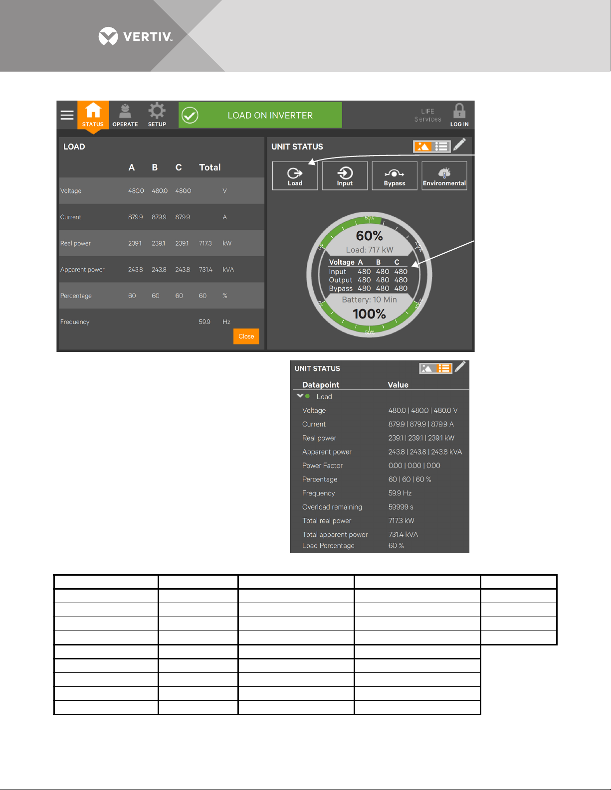
Figure 41 UNIT STATUS—Load details
GRAPHIC VIEW
TEXT VIEW
Some data in the
columns at left is
summarized in the
Status Gauge.
Touch the Load icon
to reveal the
information at left.
Data in the columns
in the graphic view is
visible in the text
view by expanding
the parameter. Here,
Load has been
expanded.
Table 3 Load menus
Voltage (L-L) Current Real (Active) Power, kW Apparent Power, kVA Power Factor
Voltage (A-B) Current A Real (Active) Power A Apparent Power A Power Factor A
Voltage (B-C) Current B Real (Active) Power B Apparent Power B Power Factor B
Voltage (C-A) Current C Real (Active) Power C Apparent Power C Power Factor C
— — Real (Active) Power Total Apparent Power Total —
Load Percentage Frequency, Hz Overload Remaining Synchronization Angle, °
Load Percentage A — — Synchronization Angle Total
Load Percentage B — — —
Load Percentage C — — —
Load Percentage Total Frequency Total Overload Remaining —
Vertiv™|Liebert® EXL™ S1 Touchscreen Control User Manual | Rev. 1 | 12/2017 | 38
Page 45

Figure 42 UNIT STATUS—Input details
GRAPHIC VIEW
Data in the columns in the graphic view
is visible in the text view by expanding
the parameter. Here, INPUT has been
expanded, showing the details.
TEXT VIEW
Some data in the
columns at left is
summarized in the
Status Gauge.
Touch the Input
icon to reveal the
information at left.
Table 4 Input menus
Voltage (L-L) Current Real Power Apparent Power Frequency
Voltage (A-B) Current A Real Power A Apparent Power A Frequency
Voltage (B-C) Current B Real Power B Apparent Power B
Voltage (C-A) Current C Real Power C Apparent Power C
— — Real Power Total Apparent Power Total
Vertiv™|Liebert® EXL™ S1 Touchscreen Control User Manual | Rev. 1 | 12/2017 | 39
Page 46

Figure 43 UNIT STATUS—Bypass details
GRAPHIC VIEW
Some data in the columns at left is
summarized in the Status Gauge.
Touch the STATUS
icon to reveal the
information at left.
Data in the columns in the graphic view is visible
in the text view by expanding the parameter.
Here, BYPASS has been expanded.
TEXT VIEW
Table 5 Bypass menus
Voltage (L-L) Current Frequency
Voltage (A-B) Current A Frequency Total
Voltage (B-C) Current B Frequency Total
Voltage (C-A) Current C Frequency Total
Real Power Apparent Power Power Factor
Real Power A Apparent Power A PF A
Real Power B Apparent Power B PF B
Real Power C Apparent Power C PF C
Real Power Apparent Power PF
Vertiv™|Liebert® EXL™ S1 Touchscreen Control User Manual | Rev. 1 | 12/2017 | 40
Page 47

Figure 44 UNIT STATUS—Battery details
GRAPHIC VIEW
TEXT VIEW
Some data in the pane at left is
summarized in the Status Gauge.
Touch the Battery
icon to reveal the
information at left.
Data in the columns in the graphic view is
visible in the text view by expanding the
parameter. Here, BATTERY has been
expanded to show overall data and
information for Cabinet 1.
Vertiv™|Liebert® EXL™ S1 Touchscreen Control User Manual | Rev. 1 | 12/2017 | 41
Page 48

Figure 45 UNIT STATUS—Environmental details
GRAPHIC VIEW
Touch the
Environmental icon
to reveal the
information at left.
TEXT VIEW
Data in the columns in the graphic view is visible
in the text view by expanding the parameter.
Here, ENVIRONMENTAL has been expanded.
Vertiv™|Liebert® EXL™ S1 Touchscreen Control User Manual | Rev. 1 | 12/2017 | 42
Page 49

4.3 Logs—Events and Log-In Times
STATUS
Touch
Events or
Logs
The Context Menu, when opened from the STATUS pane, permits viewing a log of alarms and events that have
occurred on the UPS. The log includes the date and time of occurrence, type (alarm or event), an Event ID,
component affected and a description of the alarm or event. The information is available to all users, including
Observers, those without a log-in passcode.
Events can be sorted by any of the associated information or filtered by severity (Status, Alarm and Fault) or by
component affected (bypass, monitoring or module); see 4.3.1 - Logs—Filtering and Sorting Events).
The Context Menu, when opened from the STATUS pane also permits seeing when various users logged in and
logged out—available by touching Audit Log.
To view the alarms or events:
1. Navigate to the STATUS pane.
2. Touch the Context Menu icon.
3. Touch the log to view: Events or Logs, which includes the Audit Log and UPS Event Log; see Figure 46.
Touching Events opens the list of events and alarms; touching Logs permits viewing the Audit Log or
the UPS Event Log.
Figure 46 View alarms, events, log-out times
Vertiv™|Liebert® EXL™ S1 Touchscreen Control User Manual | Rev. 1 | 12/2017 | 43
Page 50

4.3.1 Logs—Filtering and Sorting Events
Touch the Filter button to filter
events by any of the parameters
in the drop-down list.
Arrow shows events
sorted by Type.
The Events Log permits sorting Events and Filtering Events to ease understanding how the UPS is operating.
To sort events, touch on or just to the right of any of the headings—Type, Event ID, Component or Description. A
small arrow will appear beside the heading, indicating that the Events have been sorted (see Figure 47).
Figure 47 Sorting and filtering events
Sorting a list follows this logic:
•If sorting by Component, the list then sorts by Severity, then by Date/Time
• If sorting by Date/Time, the list then sorts by Component, then by Severity
• If sorting by Type, the list then sorts by Component, then by Date/Time
• If sorting by Description, the list then sorts by Date/Time
• If sorting by Event ID, the list then sorts by Date/Time.
Vertiv™|Liebert® EXL™ S1 Touchscreen Control User Manual | Rev. 1 | 12/2017 | 44
Page 51

4.4 Logs—Exporting Event and Audit Logs
Touch the
Export button.
Name the file.
Choose the file’s
destination; here
it is an SD card
on the Customer
Connections.
Choose the file’s
format, XML or
comma-separated.
Touch Save.
The Touchscreen Control Panel records and retains information about alarms, events and user log-in and log out.
Users of any access level can export these logs as either XML or CSV files for analysis or record keeping. XML
files may be opened with most text editing programs; CSV files may be opened with a spreadsheet program, such
as Microsoft® Excel™.
To export an Event Log or Audit Log:
1. Navigate to STATUS>Logs, then choose the log to be exported, either the Event Log or Audit Log.
2. Touch the Export button at the top right of the screen.
3. In the EXPORT FILE screen that opens:
a. Name the file in the Save As box (an on-screen keyboard will appear).
b. Choose the destination (this may be a memory stick inserted into the Touchscreen Control Panel).
c. Choose CSV or XML in the Format box.
d. Touch Save.
Figure 48 Exporting logs
Vertiv™|Liebert® EXL™ S1 Touchscreen Control User Manual | Rev. 1 | 12/2017 | 45
Page 52

5.0 VIEWING UPS COMPONENT STATUS
Main Input is
selected, so the
COMPONENT
DETAILS pane
shows data about
the Main Input.
The animated mimic screen permits viewing details about the main components installed in the UPS and
configured in the Touchscreen Control Panel. The data list opens on the opposite side of the screen and, for
most parameters, expands to show all details for the component selected. The information is available to anyone,
including Observers, who have no PIN number, if PIN’s are required.
Component information may also be viewed by going to STATUS Menu and touching COMPONENTS. Touching
the component name in the COMPONENTS pane brings details of the selected component in the right pane
(see Figure 49).
Figure 49 Component status—STATUS Menu
Figure 50 UNIT STATUS—Main Input details
Vertiv™|Liebert® EXL™ S1 Touchscreen Control User Manual | Rev. 1 | 12/2017 | 46
Page 53

Touching any major component on the animated mimic brings up similar details about that component of the
Bypass Details
Rectifier Details
Inverter Details
Charger/Booster Details
Battery Details
Load Details
Bypass Input Details
Liebert EXL S1. Scrolling is required to see all faults on some screens.
Figure 51 UNIT STATUS details
Vertiv™|Liebert® EXL™ S1 Touchscreen Control User Manual | Rev. 1 | 12/2017 | 47
Page 54

6.0 STATUS BAR COMPOSITION
Normal Warning Critical
The status bar indicates UPS status by:
• scrolling messages to inform viewers; see Tables 9 through 11.
• changing color; green for normal, yellow for warning and red for alarm
• showing an icon inside the bar; shown at right
6.1 Status Bar Messages
Up to three messages may scroll through the status bar to the right of
the status icon. Each message will have a duration of four seconds,
except they change immediately if the system’s status changes.
Table 6 Normal messages—Green status bar
Message 1 Message 2 Message 3 Definition
LOAD ON IN VERT ER
LOAD ON INVERTER X MODE ENABLED —
LOAD ON INVERTER X MODE ACTIVE —
LOAD ON INVERTER OPERATION NORMAL —
LOAD ON BYPASS X MODE ACTIVE —
LOAD ON BATTERY
LOAD OFF X MODE ACTIVE —
LOAD ON INVERTER SERVICE MODE ACTIVE —
LOAD ON INVERTER TEST MODE ACTIVE —
LOAD ON OTHER MODULE — —
LOAD ON BATTERY X MINUTES REMAINING —
FREQUENCY CONVERTER
MODE ACTIVE
BATTERY TEST
IN PROGRESS
OUTPUT
FREQUENCY X HZ
—
The system is in normal operating mode, supplied by the
inverter, and operating as a frequency converter.
The system is in normal operating mode, supplied by the
inverter, and has the specified energy saving modes
configured and enabled.
The system is in normal operating mode, supplied by the
inverter, and has the specified energy saving modes
active.
The system is in normal operating mode, supplied by the
inverter, and has no special configurations.
The system is in normal operating mode, supplied by the
bypass, and has the specified energy saving modes
active.
The system is in normal operating mode, supplied by the
inverter via the battery, and a battery test is running.
The system is in normal operating mode; the load is not
supplied by this unit, and has the specified energy saving
modes active.
The system is in normal operating condition on the
inverter with the service mode activated.
The system is in normal operating mode for the current
test mode that is activated.
The system is in normal operating mode, but the load is
supplied by another UPS module.
The system is operating in warning mode, supplied by the
inverter via the battery. There are X minutes of calculated
run time remaining. The precedes the battery low voltage
warning.
Vertiv™|Liebert® EXL™ S1 Touchscreen Control User Manual | Rev. 1 | 12/2017 | 48
Page 55

Table 7 Warning messages—Yellow status bar
Message 1 Message 2 Message 3 Definition
The system is operating in warning mode, supplied by the
LOAD ON INVERTER OUTPUT OVERLOAD —
LOAD ON IN VERT ER
LOAD ON IN VERT ER
LOAD ON BYPASS
LOAD ON BATTERY
LOAD ON BYPASS
LOAD ON INVERTER X MODE ENABLED
LOAD ON INVERTER X MODE ACTIVE
LOAD ON BYPASS X MODE ACTIVE
LOAD OFF X MODE ACTIVE
LOAD ON INVERTER TEST MODE ACTIVE
LOAD ON IN VERT ER
LOAD ON BYPASS TEST MODE ACTIVE
LOAD ON BYPASS
LOAD ON BATTERY TEST MODE ACTIVE
LOAD ON BATTERY
LOAD ON IN VERT ER
LOAD ON MA INT BYPASS
LOAD ON OTHER MODULE
LOAD OFF
OVER
TEMPERATURE
ALARM ACTIVE –
WARNING
LOAD MANUALLY
TRANSFERRED TO
BYPASS
X MINUTES
REMAINING
ALARM ACTIVE –
WARNING
SERVICE MODE
ACTIVE
SERVICE MODE
ACTIVE
SERVICE MODE
ACTIVE
FREQUENCY
CONVERTER MODE
ACTIVE
ALARM ACTIVE WARNING
ALARM ACTIVE –
WARNING
ALARM ACTIVE –
WARNING
VIEW EVENT LOG
FOR DETAILS
LOAD
UNPROTECTED
VIEW EVENT LOG
FOR DETAILS
ALARM ACTIVE –
WARNING
ALARM ACTIVE –
WARNING
ALARM ACTIVE –
WARNING
ALARM ACTIVE –
WARNING
ALARM ACTIVE –
WARNING
ALARM ACTIVE –
WARNING
ALARM ACTIVE –
WARNING
ALARM ACTIVE –
WARNING
ALARM ACTIVE –
WARNING
ALARM ACTIVE –
WARNING
ALARM ACTIVE –
WARNING
VIEW EVENT LOG
FOR DETAILS
VIEW EVENT LOG
FOR DETAILS
VIEW EVENT LOG
FOR DETAILS
—
—
inverter, and the system is in overload. The system will go off
inverter at some point.
The system is operating in warning mode, supplied by the
inverter, and at least one part of the system is incurring an
overtemperature alarm. This means if the temperature does not
recover, the system will go off inverter at some point.
The system is operating in warning mode, supplied by the
inverter, and has an active alarm.
The system is operating in warning mode, supplied by the
bypass. The user transferred the load to the bypass so the
system cannot protect itself from source variations.
The system is operating in warning mode, supplied by the
inverter via the battery. There are X minutes of calculated run
time remaining. This precedes the battery low voltage warnings.
The system is operating in warning mode, supplied by the
bypass, and has an active alarm.
The system is operating in warning mode, supplied by the
inverter, the specified energy saving modes is configured and
enabled, and has an active alarm.
The system is operating in warning mode, supplied by the
inverter, the specified energy saving modes is active, and has an
active alarm.
The system is operating in warning mode, supplied by the
bypass, the specified energy saving modes is active, and has an
active alarm.
The system is operating in warning mode, load off, the specified
energy saving modes is active, and has an active alarm.
The system is operating in warning mode, supplied by the
inverter, running in a system test mode, and has an active alarm.
The system is operating in warning mode, supplied by the
inverter, running in a service mode, and has an active alarm.
The system is operating in warning mode, supplied by the
bypass, running in a system test mode, and has an active alarm.
The system is operating in warning mode, supplied by the
bypass, running in a service mode, and has an active alarm.
The system is operating in warning mode, supplied by the
battery, running in a system test mode, and has an active alarm.
The system is operating in warning mode, supplied by the
battery, running in a service mode, and has an active alarm.
The system is operating in warning mode, supplied by the
inverter, operating as a frequency converter, and has an active
alarm.
The system is operating in warning mode, supplied by the
maintenance bypass, and has an active alarm.
The module is operating in warning mode. The load is supplied
by other UPS modules, and has an active warning.
The module is operating in warning mode. The load is not
supplied, and has an active warning.
Vertiv™|Liebert® EXL™ S1 Touchscreen Control User Manual | Rev. 1 | 12/2017 | 49
Page 56

Table 8 Critical messages—Red status bar
Message 1 Message 2 Message 3 Definition
LOAD ON INVERTER OUTPUT OVERLOAD
LOAD ON INVERTER FAULT ACTIVE - CRITICAL
LOAD ON BYPASS
LOAD ON BYPASS FAULT ACTIVE - CRITICAL
LOAD ON BATTERY X MINUTES REMAINING
LOAD OFF FAULT ACTIVE - CRITICAL
LOAD OFF — —
LOAD ON BATTERY FAULT ACTIVE - CRITICAL
LOAD ON INVERTER X MODE ENABLED
LOAD ON INVERTER X MODE ACTIVE
LOAD ON BYPASS X MODE ACTIVE
LOAD OFF X MODE ACTIVE
LOAD OFF TEST MODE ACTIVE — The system is Off with TEST MODE active.
LOAD OFF SERVICE MODE ACTIVE — The system is Off with SERVICE MODE active.
LOAD ON INVERTER TEST MODE ACTIVE
LOAD ON INVERTER SERVICE MODE ACTIVE
LOAD ON BYPASS TEST MODE ACTIVE
LOAD ON BYPASS SERVICE MODE ACTIVE
LOAD AUTOMATICALLY
TRANSFERRED TO BYPASS
TRANSFER TO
BYPASS PENDING
VIEW EVENT LOG
FOR DETAILS
VIEW EVENT LOG
FOR DETAILS
VIEW EVENT LOG
FOR DETAILS
LOAD SHUTDOWN
IMMINENT
VIEW EVENT LOG
FOR DETAILS
VIEW EVENT LOG
FOR DETAILS
FAULT ACTIVE CRITICAL
FAULT ACTIVE CRITICAL
FAULT ACTIVE CRITICAL
FAULT ACTIVE CRITICAL
FAULT ACTIVE CRITICAL
FAULT ACTIVE CRITICAL
FAULT ACTIVE CRITICAL
FAULT ACTIVE CRITICAL
The system is in critical operating mode, supplied by the
inverter, and the load is about to be transferred to the
bypass due to overload timeouts.
The system is in critical operating mode, supplied by the
inverter. There is a critical fault raised in the system that
the user needs to check.
The system is in critical operating mode, supplied by the
bypass. The system moved the load to the bypass due to
a critical fault in the system.
The system is in critical operating mode, supplied by the
bypass. The system is running on bypass not due to autotransfer, and a critical fault is active in the system.
The system is in critical operating mode, supplied by the
inverter via the battery. The battery is extremely low and
the load will turn Off or transfer to bypass soon.
The system is in critical operating mode, the load is not
supplied by this unit and a critical fault is active.
The system is in critical operating mode, the load is not
supplied and no active fault is present.
The system is in critical operating mode, the system is
running on inverter via the battery, shutdown is not
imminent and a critical fault is active in the system.
The system is in critical operating mode, the system is
running on inverter, with the specified energy saving
mode configured and enabled, and a critical fault is active
in the system.
The system is in critical operating mode, supplied by the
inverter. The system is running on inverter, with the
specified energy saving mode active, and a critical fault is
active in the system.
The system is in critical operating mode, the system is
running on bypass, with the specified energy saving
mode active, and a critical fault is active in the system.
The system is in critical operating mode. The system is
NOT running, with the specified energy saving mode
active, and a critical fault is active in the system.
The system is in critical operating mode, supplied by the
inverter, running in a system test mode, and has an active
fault.
The system is in critical operating mode, supplied by the
inverter, running in a system service mode, and has an
active fault.
The system is in critical operating mode, supplied by the
bypass, running in a system test mode, and has an active
fault.
The system is in critical operating mode, supplied by the
bypass, running in a system service mode, and has an
active fault.
Vertiv™|Liebert® EXL™ S1 Touchscreen Control User Manual | Rev. 1 | 12/2017 | 50
Page 57

Table 8 Critical messages—Red status bar (continued)
Message 1 Message 2 Message 3 Definition
The system is in critical operating mode, supplied by the
inverter via the battery, running in a system test mode,
and has an active fault.
The system is in critical operating mode, supplied by the
inverter via the battery, running in a system service mode,
and has an active fault.
The system is in critical operating mode, with LOAD OFF,
running in a system test mode, and has an active fault.
The system is in critical operating mode, with LOAD OFF,
running in a system service mode, and has an active fault.
The system is in critical operating mode, supplied by the
inverter, operating as a frequency converter, and has an
active fault.
The system is in critical operating mode, operating as a
frequency converter, has an active fault and the load is
not supplied.
The system is in critical operating mode, supplied by the
maintenance bypass. There is a critical fault raised in the
system that the user needs to check.
The module is in critical operating mode. The load is
supplied by other UPS modules. There is a critical fault in
the system that the user needs to check.
LOAD ON BATTERY TEST MODE ACTIVE
LOAD ON BATTERY SERVICE MODE ACTIVE
LOAD OFF TEST MODE ACTIVE
LOAD OFF SERVICE MODE ACTIVE
LOAD ON INVERTER
LOAD OFF
LOAD ON MAINT BYPASS FAULT ACTIVE – CRITICAL
LOAD ON OTHER MODULE FAULT ACTIVE – CRITICAL
FREQUENCY CONVERTER
MODE ACTIVE
FREQUENCY CONVERTER
MODE ACTIVE
FAULT ACTIVE CRITICAL
FAULT ACTIVE CRITICAL
FAULT ACTIVE CRITICAL
FAULT ACTIVE CRITICAL
FAULT ACTIVE CRITICAL
FAULT ACTIVE CRITICAL
VIEW EVENT LOG
FOR DETAILS
VIEW EVENT LOG
FOR DETAILS
Vertiv™|Liebert® EXL™ S1 Touchscreen Control User Manual | Rev. 1 | 12/2017 | 51
Page 58

7.0 LIEBERT EXL S1 EVENTS, WARNINGS AND ALARMS
Table 9 Liebert EXL S1 Status Events
Component Type Text Display ID Description
Battery Status Battery warning 04-000 A warning is pending.
Battery Status Battery fault 04-001 A fault is pending.
Battery Status Battery idle 04-002 The battery is idle; energy is flowing neither in nor out.
Battery Status Battery is discharging 04-004 The battery is discharging.
Battery Status Automatic Battery Test Started 04-032 An automatic battery test has been started.
Battery Status Battery Test Requested 04-033 (Not supported) see BAW1 bit 4
Battery Status Battery Test Failed 04-035
Battery Status Battery Test Idle 04-048 The battery test function is not being performed.
Battery Status Battery Test Start Pending 04-052
Battery Status Battery Test Stop Pending 04-053
Battery Status Battery Non-Blocking Fault 04-054 Set when a non-blocking fault is active in the stage.
Battery Status Battery Not Connected 04-065
Battery Status Battery is charging 14-003 The battery is being charged.
Battery Status Battery Test Running 14-034 Battery test is running.
Battery Status Battery Test Not Allowed 14-036 Conditions preclude performing a battery test.
Battery Status Battery Test Finished OK 14-037
Battery Status Battery Test Canceled 14-038 (Not supported)
Battery Status Battery Test Interrupted 14-050 (Not supported)
Battery Status Battery Test Stopped by User 14-051
Bypass Status Bypass is not present 01-000 —
Bypass Status Bypass Is On 01-001 —
Bypass Status Bypass Is Off 01-002 —
Bypass Status Bypass is stopped due to a fault 01-003 —
Bypass Status Bypass not prepared 01-004
Bypass Status Bypass fault 01-005 Set when a blocking fault is active in the stage.
Bypass Status Bypass warning 01-007 Set when at least one warning is active.
Bypass Status Bypass available with delay 01-008 Set when the bypass and inverter are not synchronized.
Bypass Status Parallel bypass OK 01-029 All bypass inputs are OK.
Bypass Status Parallel bypass one fault 01-030 One bypass input fault exists.
Bypass Status Parallel bypass at least one OK 01-031 At least one bypass input is OK.
Bypass Status Parallel bypass fault 01-032 All bypass inputs are in fault.
Bypass Status Undelayed Bypass Ref. Failure 01-040 Bypass reference failure notification without any delay.
Bypass Status Bypass is Centralized 01-041
A battery test has failed. Permanent state: a manual reset
is required.
In a parallel system with a common battery, the Start
command is present on some but not all the units.
In a parallel system with a common battery, the Stop
command is present on some but not all the units.
Set when V_BATT1 < 100V (fix threshold). Control always
active independently to battery breaker status.
Battery test finished; active for 5 seconds, then switches
to Battery Test Idle.
User has stopped the battery test; active for 5 seconds,
then switches to Battery Test Idle. Valid only for a manual
battery test.
Static switch board is not installed or the bypass voltage
is over the threshold (P 106.i04).
The internal bypass is disabled; the UPS is using the
centralized / common (MSS) bypass.
Vertiv™|Liebert® EXL™ S1 Touchscreen Control User Manual | Rev. 1 | 12/2017 | 52
Page 59

Table 9 Liebert EXL S1 Status Events (continued)
Component Type Text Display ID Description
Bypass Status Bypass Non-Blocking Fault 01-042 Set when a non-blocking fault is active in the stage.
Bypass Status Bypass Global On Request 01-078
Bypass Status Bypass Global On 01-079
Bypass Status Bypass Global Off 01-080
Bypass Status Bypass mains is out of tolerance 11-006 Bypass failure notification without any delay.
Bypass Alarm Bypass Input Switch Open 21-012 Bypass input switch is open.
Charger/Booster Status Charger in Standby - (not charging) 03-000 —
Charger/Booster Status Charger is on 03-001 —
Charger/Booster Status Charger is off 03-002 —
Charger/Booster Status Charger Forced On 03-003 —
Charger/Booster Status Charger Stopped due to a Fault 03-038 —
Charger/Booster Status Charger in Current Limitation 03-039
Charger/Booster Status Charging Status OFF 03-040 —
Charger/Booster Status Charging Status INIT 03-041 —
Charger/Booster Status Charging Status FLOAT 1 03-042 —
Charger/Booster Status Charging Status FLOAT 2 03-043 —
Charger/Booster Status Charging Status POST 03-044 —
Charger/Booster Status Charging Status PAUSE 03-045 —
Charger/Booster Status Charging Status MANUAL 03-046 —
Charger/Booster Status Charging Status FAULT 03-047 —
Charger/Booster Status Buck-Booster Fault 03-048 At least one fault is active.
Charger/Booster Status Buck-Booster Warning 03-049 Set when at least one warning is active.
Charger/Booster Status Booster Off 03-050 —
Charger/Booster Status Booster Turning On 03-051 —
Charger/Booster Status Booster On 03-052 —
Charger/Booster Status Booster Stopped Due To Fault 03-053 —
Charger/Booster Status Booster Runs From Battery 03-054 Status set after a fixed delay equivalent to P1110.
Charger/Booster Status Buck-Booster Non-Blocking Fault 03-055 At least one non-blocking fault is active.
Charger/Booster Status DC Bus Too Low To Charge 03-061 —
General Status Warning pending 00-000 Set when at least one stage in the core is in warning.
General Status Fault pending 00-001 Set when at least one stage in the core is in fault.
General Status General Fault 00-002 Set when a fault is active in general stage.
General Status Parallel Unit 00-003 Set when P129 = 1.
General Status External Synch enabled 00-005 Set when P700 = 1.
General Status Inverter/Rectifier OFF Command Issued 00-006
General Status Inverter on rectifier 00-009 Inverter is supplied by the rectifier.
General Status Inverter on battery 00-010 Inverter is supplied by the battery.
Bypass Static Switch On command request on the shared
bus
Bypass Static Switch on global status read from the
shared bus.
Bypass Static Switch Off Global status read from the
shared bus.
Displayed as long as the voltage reference is lower than
the nominal.
Set when command UPS Off is received; resets when
command is not present.
Vertiv™|Liebert® EXL™ S1 Touchscreen Control User Manual | Rev. 1 | 12/2017 | 53
Page 60

Table 9 Liebert EXL S1 Status Events (continued)
Component Type Text Display ID Description
General Status Parameter reset active 00-011
General Status Intelligent Parallel Not Allowed 00-014
General Status Core Running 00-016 Core running.
General Status Operating Request for VFI 00-102 —
General Status SKRU: Inverter start inhibited 00-131
General Status General Warning 00-146 Set when a warning is active in the general stage.
General Status General Non-Blocking Fault 00-147 Set when a non-blocking fault is active in general stage.
General Status Non-Blocking Fault pending 00-148
General Status General Fault 00-171 Set when a fault is active in general stage.
General Status General Warning 00-172 Set when a warning is active in general stage.
General Status General Non-Blocking Fault 00-173 Set when a non-blocking fault is active in general stage.
General Status General Core Summary Warning 00-174
General Status General Core Summary Fault 00-175
General Status General Core Non-Blocking Fault 00-176
General Status Manual Mode Command Pending 00-200
General Status Synchronize Rectifier Mains Failure 00-219
General Status One or More Fans Not Working 00-221
General Status BCB: Trip command issued 00-226
General Status Operating Request for Intelligent ECO 00-273 —
General Status Core Sleeping 10-015 Core is sleeping.
General Status Intelligent ECO Enabled 10-204 —
General Status Intelligent Parallel Enabled 10-205 —
General Status Fan Test in Progress 10-220
Inverter Status Inverter is off 06-000 —
Inverter Status Inverter is turning on 06-001 —
Inverter Status Inverter is on 06-002 —
Inverter Status Inverter is stopped due to a fault 06-003 —
Inverter Status Inverter fault 06-004
Inverter Status Synchronization Source: Bypass 06-005 —
Inverter Status Synchronization Source: Output 06-006 —
Inverter Status Synchronization Source: Self Clock 06-007 —
Inverter Status Synchronization Source: External 06-008 —
Set after a parameter reset. Resets as soon as the
parameter is written.
Inverter status is not compatible with circular
redundancy.
Inverter board will check the status of the input/output
contact Function #16 to inhibit the inverter start.
Set when at least one stage in the CORE is in a
non-blocking fault.
Set when a customer blocking fault flag is present (not
yet defined).
Set when at least one customer warning is active. (Not
yet defined)
Set when a customer non-blocking fault in stage is set
(not yet defined).
Set when Trinergy Manual command is pending but
global status not confirmed.
Request to synchronize the rectifier in case mains failure
affects only one core or unit.
Set when one fan out of the entire set of monitored fans
is not working.
Enabled by Output Function 47 BCB trip. Battery Circuit
Breaker (BCB) opening command has been issued.
Set when fan test is in progress. Valid for either
Automatic or Manual.
Set when a blocking fault is present on the inverter
stage.
Vertiv™|Liebert® EXL™ S1 Touchscreen Control User Manual | Rev. 1 | 12/2017 | 54
Page 61

Table 9 Liebert EXL S1 Status Events (continued)
Component Type Text Display ID Description
Inverter Status Inverter warning 06-010 Set when at least 1 warning is active
Inverter Status Inverter out of Synchronization 06-011
Inverter Status Inverter out of Synchronization 06-016
Inverter Status Online operation / VFI 06-018 —
Inverter Status VI 06-019 —
Inverter Status Intelligent ECO / VFD 06-020 —
Inverter Status Intelligent Parallel / CR 06-079 —
Inverter Status Intelligent Parallel / CR 06-079 —
Inverter Status Intelligent Parallel / CR 06-079 —
Inverter Status Operation: ECO mode 06-086
Inverter Status Inverter in Standby 06-087 —
Inverter Status Inverter Ready and Sync 06-088 —
Inverter Status Inverter Not Ready 06-089 —
Inverter Status Current Limit Last more then 3ms 06-090 Current limit lasts > 3 ms.
Inverter Status Inverter Non-Blocking Fault 06-091 Set when a non-blocking fault is active in the stage.
Inverter Status Inverter Fault 06-110 Set when CUSTOMER blocking fault flag is present.
Inverter Status Inverter warning 06-111 Set when at least one customer warning is active.
Inverter Status Inverter Non-Blocking Fault 06-112 Set when a customer non-blocking fault in stage is set.
Inverter Status Inverter pending on command 16-029 —
Load Status Load supplied by bypass 07-001
Load Status Load Supplied By Maint. Bypass 07-002 Set when load is supplied by Manual Bypass
Load Status Load is currently not supplied 07-003 Set when module is not supplying load
Load Status Load on low priority line 07-004
Load Status Load on phase U-A > 85% 07-005 —
Load Status Load on phase V-B > 85% 07-006 —
Load Status Load on phase W-C > 85% 07-007 —
Load Status Load warning 07-008 Set when at least one warning is active.
Load Status Load supplied by battery 07-026
Load Status Load Secured by Inverter 07-027
Load Status Load Fault 07-028
Load Status Load Non-Blocking Fault 07-029
MUN Status MUN has a warning 08-000
MUN Status MUN has a fault 08-001
Set when the inverter is not synchronized with local
bypass
Set when the inverter is not synchronized with external
synchronization signal.
Active if inverter is turning On, the load is on Bypass and
P580=1 (DIM enabled).
Set when load is supplied by Automatic Bypass and
Inverter is OFF
Set when the load is supplied by the inverter and P568=1
or when the load is supplied by the bypass and P580=0.
Set when the load is secured by the inverter and energy
is provided by the battery.
Set when the load is secured by the inverter. This
includes the inverter in VFI or DIM (Eco) Mode.
Set when a blocking fault is present in the actual stage
(not yet implemented)
Set when a non-blocking fault is present in the actual
stage (not yet implemented).
Set when at least one MUN stage is in warning. (MUN is
Managed Ups Network, a controller component.)
Set when at least one non-blocking fault is present on
MUN. (MUN is Managed Ups Network, a controller
component.)
Vertiv™|Liebert® EXL™ S1 Touchscreen Control User Manual | Rev. 1 | 12/2017 | 55
Page 62

Table 9 Liebert EXL S1 Status Events (continued)
Component Type Text Display ID Description
MUN Status UPS Model detection in progress 08-003 MUN is searching for Model Information.
MUN Status MUN initialisation done 08-004 MUN is setup with autodetection.
MUN Status MUN reboot required 08-005 MUN detects difference in environment variable
MUN Status System Started 08-011
MUN Status Acknowledge Button Pressed 08-025 Acknowledge button has been pressed
MUN Status UPS Time not valid 08-026 Set when date is < 1 Jan 2009.
MUN Status Life call in progress 08-033 Call in progress.
MUN Status Life call rescheduled 08-034 Call rescheduled.
MUN Status Life modem not detected 08-035 Set when MUN does not receive replies from modem
MUN Status Parameter read failed 08-054
MUN Status Parameter set failed 08-055
MUN Status Life Service Mode 08-060
MUN Status Ntp is Disconnected from Touchscreen 08-061 to be filled in
MUN Status Life interface Init in Progress 08-079 Set at mund application startup; reset after one second
MUN Status Life Events Sampling started 08-095
MUN Status MUN/DSP are not Sync with SYNW 08-097 —
MUN Status Life Measures Sampling Started 08-098
MUN Status System Time Moved Ahead 08-110
MUN Status System Time Moved Back 08-111
Rectifier Status Rectifier is off 02-000 —
Rectifier Status Rectifier is turning on 02-001 —
Rectifier Status Rectifier is on 02-002 —
Rectifier Status Rectifier fault 02-004 Set either blocking or non blocking
Rectifier Status Rectifier Warning 02-009 Set when at least 1 warning is active
Rectifier Status No precharge in progress 02-010
Rectifier Status Precharge in progress 02-011 Hold off delay and resistor pre-charge
Rectifier Status Walk-in in progress 02-012 Rectifier current limit ramp.
Rectifier Status Precharge finished 02-013 Pre-charge finished. Active while mains is OK
Rectifier Status Rectifier Power Limitation Active 02-048
Rectifier Status Rectifier Current Limit 02-049
Set at mund Application startup; never reset. (mund is
the application name for Managed Ups Network,)
Parameter can not be read from DSP.
• Set when Parameter Reading returns with an
exception
• Reset when Parameter Reading returns with an OK.
Parameter can not be written to DSP.
• Set when Parameter Writing returns with an
exception.
• Reset when Parameter Writing returns with an OK.
Life is in Service mode, so emergency calls are not sent
to station (used when an SE is operating on the device in
field).
Ignore events history and restart sampling from current
time.
Ignore measures history and restart sampling from
current time.
Set when device time is moved ahead after time
adjustment from Life Station.
Set when device time is moved back after time
adjustment from Life Station.
No pre-charge active. Active while mains is out of
tolerance
Set when the input current is limited by standard or
customer limit.
Set when input current reaches the limit defined by
P 1740.11 and lasts more 3 ms but less 10 ms.
Vertiv™|Liebert® EXL™ S1 Touchscreen Control User Manual | Rev. 1 | 12/2017 | 56
Page 63

Table 9 Liebert EXL S1 Status Events (continued)
Component Type Text Display ID Description
Rectifier Status Rectifier Non-Blocking Fault 02-050 Set when a non-blocking fault in rectifier stage is set.
Rectifier Status Rectifier fault 02-070
Rectifier Status Rectifier Warning 02-071
Rectifier Status Rectifier Non-Blocking Fault 02-072
Rectifier Status Rectifier Stopped - Fault 02-092 —
Rectifier Status Rectifier Inhibited 02-093
Rectifier Status Rectifier mains is out of tolerance 12-005 Mains failure notification without any delay.
Set when CUSTOMER blocking fault flag is present. (Not
yet defined)
Set when at least one customer warning is active (not yet
defined).
Set when a customer non-blocking fault in stage is set
(not yet defined).
Set when the rectifier pulse is inhibited due to DC
overvoltage.
Table 10 All EXL S1 Events - Alarms
Component Type Text Display ID Description
The battery voltage is under the shutdown voltage
defined by 5 points of P1513 Shutdown Voltage Table.
Battery Alarm Battery under voltage 24-012
Battery Alarm High battery temperature 24-015
Battery Alarm Battery temperature out of range 24-016
Battery Alarm Temperature Probe Broken 24-017
Battery Alarm Battery Switch Wiring Fault 24-056
Battery Alarm Cubicle Battery Switch Open 24-063
Battery Alarm Battery Is Not Connected 24-064 Battery is not connected - warning.
Battery Alarm Imminent End Of Autonomy - Volt 24-066
Battery Alarm Imminent End Of Autonomy - Time 24-067
Battery Alarm BCB Breaker Open 24-068
Battery Alarm Battery Breaker Open 24-072 One or more BIB boards report an open breaker.
Bypass Alarm Bypass Input Switch Open 21-012 Bypass input switch is open.
Bypass Alarm Bypass mains failure 21-013 Warning set after delay defined by P 110
Bypass Alarm Bypass in Overload Condition 21-014 —
Bypass Alarm Bypass disabled 21-016
Bypass Alarm Bypass overtemperature 21-017 Set when inverter temp. P 151.01 < T < P 151.02.
This warning causes the inverter to stop. This warning will
be kept as long as the battery voltage is lower than the
Inverter Restart Threshold.
Remote Battery Monitoring battery temperature user
alarm (Temp. P1533.1 < T < P1533.2).
RBM battery temperature is out of range
-10°C < T < P 1533.1 or 1533.2 < T < 40°.
RBM temperature probe is not responding
(Temp. T < 10°C or T > 50°C or RBM Sensor Status
[bit 3-2] = 11.
Core only: Set when the RBM option is installed with Form
C wiring and related cubicle breaker wiring fails.
Core and Monolithic.
• CORE: set when an RBM option is installed.
• Monolithic: set when IO Function 18 is enabled.
Set if P1590 = 2 or 3.The battery voltage is lower than the
threshold defined by 5 points of P1513 Shutdown Voltage
Tab le + P 1591 Delta shutdown imminent.
Set if P1590 = 1 or 3. The autonomy is below the defined
threshold P1117 Battery stored energy time limit.
Enabled by Input Function 21 BCB. Battery Circuit Breaker
(BCB) is open.
Bypass ON command disabled (SW bypass inhibition to
avoid DC capacitor overcurrent. Detected on DIC Inv.
when DC link higher than ([SQRT2 * Phase voltage RMS] 30V), delay 0.4 seconds).
Vertiv™|Liebert® EXL™ S1 Touchscreen Control User Manual | Rev. 1 | 12/2017 | 57
Page 64

Table 10 All EXL S1 Events - Alarms (continued)
Component Type Text Display ID Description
Bypass Alarm Bypass mode not auto 21-018
Bypass Alarm Parallel Bypass Failure 21-038 Set when the input Bypass OK is set.
Bypass Alarm Bypass Wrong Phase Rotation 21-083 Bypass input wrong phase rotation.
Charger/Booster Alarm Battery Not Connected 23-012
Charger/Booster Alarm Reversed polarity 23-014
Charger/Booster Alarm Buck-Booster DC Voltage Low 23-056
Charger/Booster Alarm Buck-Booster Overtemperature 23-057
Charger/Booster Alarm Buck-Booster B Overtemperature 23-067
Charger/Booster Alarm DC Overvoltage 23-080
General Alarm System Power UP 00-023 —
General Alarm Commissioning / Test Mode 20-018 —
General Alarm System Maint. Bypass Switch Closed 20-019 —
General Alarm Synchronization system fault 20-022 —
General Alarm System shutdown 20-024 —
General Alarm The ID Card is missing 20-025 —
General Alarm Calibration is started 20-026 —
General Alarm Input Air High Temperature 20-027 —
General Alarm System Output Switch Open 20-031 —
General Alarm System Bypass Switch Closed 20-032 —
General Alarm Detected Cores Mismatch 20-127 —
General Alarm Communication Loss BIB 20-132 —
General Alarm AC Ground Fault 20-133 —
General Alarm Communication Loss MI Ph. U-A 20-153 —
General Alarm Communication Loss MI Ph. V-B 20-154 —
General Alarm Communication Loss MI Ph. W-C 20-155 —
General Alarm Communication Loss MI BB 20-156 —
General Alarm Motherboard Overtemperature 20-165 —
General Alarm PIB Overtemperature 20-166 —
General Alarm Cable Conduit Overtemperature 20-167 —
General Alarm MIB Overtemperature 20-168 —
General Alarm Duplicated Parallel Unit Id 20-169 —
General Alarm Parallel Unit Number Mismatch 20-170 —
General Alarm Communication Loss MI-B Ph. U-A 20-206 —
General Alarm Communication Loss MI-B Ph. V-B 20-207 —
General Alarm Communication Loss MI-B Ph. W-C 20-208 —
Set when the Bypass Control CAN ID 04002300h is not
AUTO. Normally set in Power Circuit Test page.
Set when -100V < V_BATT1 < 100V (fix threshold). Control
always active independently of battery breaker status.
Set when V_BATT1 < -100V (fix threshold). Control always
active independently to Battery breaker status. Inhibits
starting the battery charger.
Booster inhibit when DC voltage < P1135.i03 (to be
verified).
Set when the temperature is greater than the P 1151 value
(see Overload specification)
Set when the temperature is greater than the P 1151 value
(see Overload specification)
Set when the DC bus voltage crosses the maximum
threshold of P1753.30 for P1753.31 time.
Vertiv™|Liebert® EXL™ S1 Touchscreen Control User Manual | Rev. 1 | 12/2017 | 58
Page 65

Table 10 All EXL S1 Events - Alarms (continued)
Component Type Text Display ID Description
General Alarm Communication Loss MI-B BB 20-209 —
General Alarm Fan Failure Phase U 20-210 —
General Alarm Fan Failure Phase V 20-211 —
General Alarm Fan Failure Phase W 20-212 —
General Alarm Fan Failure Buck-Booster 20-213 —
General Alarm Battery Switch Open - Do Not Close 20-214 —
General Alarm CPU Time Slice 20-215 —
General Alarm Fan Failure Static Switch 20-222 —
General Alarm Fan Failure Board Slot 20-223 —
General Alarm I/O Transformer Overtemperature 20-224 —
General Alarm DC Overvoltage 20-227 —
General Alarm Communication Loss PIB-S1 20-243 —
General Alarm Communication Loss PIB-S1 20-244 —
General Alarm Communication Loss PIB-S1- I2C 20-245 —
Inverter Alarm Inverter DC Undervoltage 26-025 Inverter inhibit when DC voltage < P135.i04.
Inverter Alarm Inverter overload 26-026 RMS overload condition.
Inverter Alarm The inverter is off 26-027 —
Inverter Alarm Inverter pending off command 26-028 —
Set when the overload timeout has reached 100%. This
Inverter Alarm Inverter overload 26-031
Inverter Alarm Overtemperature Phase U-A 26-101
Inverter Alarm Overtemperature Phase V-B 26-102
Inverter Alarm Overtemperature Phase W-C 26-103
Inverter Alarm Overtemperature B Phase U-A 26-119
Inverter Alarm Overtemperature B Phase V-B 26-120
Inverter Alarm Overtemperature B Phase W-C 26-121
Inverter Alarm DC Overvoltage 26-137
Load Alarm Output Switch Open 27-009 The output breaker MOB is open.
Load Alarm Load is currently not supplied 27-010 Monolithic only: UPS is not supplying the load
Load Alarm Retransfer is inhibited 27-011
MUN Status MUN has a warning 08-000 Set when at least one MUN stage is in warning.
MUN Status MUN has a fault 08-001
MUN Status UPS Model detection in progress 08-003 MUN is searching for model information
MUN Status MUN initialisation done 08-004 MUN is setup with autodetection.
triggers the request to transfer to bypass with default
configuration.
Set when Phase U temperature is greater than the value
specified by P 151.
Set when Phase V temperature is greater than the value
specified by P 151.
Set when Phase W temperature is greater than the value
specified by P 151.
Set when Phase U temperature is greater than the value
specified by P 151.
Set when Phase V temperature is greater than the value
specified by P 151.
Set when Phase W temperature is greater than the value
specified by P 151.
Set when DC bus voltage crosses the maximum threshold
P753.40 for P753.41 time.
Load transfer to inverter inhibited due to overload (to be
verified with overload specification).
Set when at least one non-blocking fault is present on
MUN.
Vertiv™|Liebert® EXL™ S1 Touchscreen Control User Manual | Rev. 1 | 12/2017 | 59
Page 66

Table 10 All EXL S1 Events - Alarms (continued)
Component Type Text Display ID Description
MUN Status MUN reboot required 08-005 MUN detects difference in environmental variables.
MUN Status System Started 08-011 Set at mund application startup; never reset
MUN Status Acknowledge Button Pressed 08-025 Acknowledge button has been pressed.
MUN Status UPS Time not valid 08-026 set when date is < 1 Jan 2009
MUN Status Life call in progress 08-033 Call in progress
MUN Status Life call rescheduled 08-034 Call rescheduled
MUN Status Life modem not detected 08-035 Set when MUN does not receive replies from modem.
Parameter can not be read from DSP.
MUN Status Parameter read failed 08-054
MUN Status Parameter set failed 08-055
MUN Status Life Service Mode 08-060
MUN Status Ntp is Disconnected from Touchscreen 08-061 —
MUN Status Life interface Init in Progress 08-079 Set at mund application startup; reset after one second.
MUN Status Life Events Sampling started 08-095
MUN Status MUN/DSP are not Sync with SYNW 08-097 —
MUN Status Life Measures Sampling Started 08-098
MUN Status System Time Moved Ahead 08-110
MUN Status System Time Moved Back 08-111
MUN Alarm CAN Communication Loss 28-008
MUN Alarm UPS Model cannot be identified 28-056 UPS model not detected.
Rectifier Status Rectifier is off 02-000 —
Rectifier Status Rectifier is turning on 02-001 —
Rectifier Status Rectifier is on 02-002 —
Rectifier Status Rectifier fault 02-004 Set as either blocking or non-blocking.
Rectifier Status Rectifier Warning 02-009 Set when at least one warning is active.
Rectifier Status No precharge in progress 02-010
Rectifier Status Precharge in progress 02-011 Hold off delay and resistor pre-charge.
Rectifier Status Walk-in in progress 02-012 Rectifier current limit ramp.
Rectifier Status Precharge finished 02-013 Pre-charge finished. Active while mains is OK.
Rectifier Status Rectifier Power Limitation Active 02-048
Rectifier Status Rectifier Current Limit 02-049
Rectifier Status Rectifier Non-Blocking Fault 02-050 Set when a non-blocking fault in rectifier stage is set.
• Set when Parameter Reading returns with an
exception.
• Reset when Parameter Reading returns with OK.
Parameter cannot be written to DSP.
• Set when Parameter Writing returns with an
exception.
• Reset when Parameter Writing returns with OK.
Life is in Service Mode, so emergency calls are not sent to
station. (Used when an SE is operating on the device.)
Ignore events history and restart sampling from current
time.
Ignore measures history and restart sampling from
current time.
Set when device time is moved ahead after time
adjustment from Life Station.
Set when device time is moved back after time
adjustment from Life Station.
Set when CAN telegram are not received for 10 seconds.
Reset when a general stage telegram is received.
No pre-charge active. Active while mains is out specified
limits.
Set when the input current is limited by standard or
customer limit.
Set when input current reaches the limit defined by
P 1740.11 and lasts more 3 ms but less 10 ms.
Vertiv™|Liebert® EXL™ S1 Touchscreen Control User Manual | Rev. 1 | 12/2017 | 60
Page 67

Table 10 All EXL S1 Events - Alarms (continued)
Component Type Text Display ID Description
Rectifier Status Rectifier fault 02-070
Rectifier Status Rectifier Warning 02-071
Rectifier Status Rectifier Non-Blocking Fault 02-072
Rectifier Status Rectifier Stopped - Fault 02-092 —
Rectifier Status Rectifier Inhibited 02-093
Rectifier Status Rectifier mains is out of tolerance 12-005 Mains failure notification without any delay.
Rectifier Alarm Rectifier Input Switch Open 22-014 —
Rectifier Alarm Rectifier mains failure 22-015 Warning set after the delay defined by P1110.
Rectifier Alarm Wrong phase rotation 22-017 Input line phase rotation is incorrect.
Rectifier Alarm DC voltage low 22-018
Rectifier Alarm Out of synchronization 22-020
Rectifier Alarm Peak Input Voltage 22-021
Rectifier Alarm Overtemperature Phase U-A 22-061
Rectifier Alarm Overtemperature Phase V-B 22-062
Rectifier Alarm Overtemperature Phase W-C 22-063
Rectifier Alarm Overtemperature B Phase U-A 22-073
Rectifier Alarm Overtemperature B Phase V-B 22-074
Rectifier Alarm Overtemperature B Phase W-C 22-075
Rectifier Alarm DC Overvoltage 22-102
Set when a customer blocking fault flag is present (not
yet defined).
Set when at least one customer warning is active (not yet
defined).
Set when a customer non-blocking fault in stage is set.
(not yet defined).
Set when the rectifier pulse is inhibited due to DC
overvoltage.
DC link voltage under the threshold defined by P1135.2,
causing PWM inhibition.
During the rectifier running it causes the rectifier to stop
temporarily.
Mains voltage high peak detector trips when
instantaneous voltage exceeded the limit defined by
P1140.i05.
Set when Phase U temperature is greater then P 1151
setting (Def = 80°C)
Set when Phase V temperature is greater then P 1151
setting (Def = 80°C).
Set when Phase W temperature is greater then P 1151
setting (Def = 80°C).
Set when Phase U temperature is greater then P 1151
setting (Def = 80°C).
Set when Phase V temperature is greater then P 1151
setting (Def = 80°C).
Set when Phase W temperature is greater then P 1151
setting (Def = 80°C).
Set when the rectifier detects DC bus voltage above
threshold P1753.29.
Vertiv™|Liebert® EXL™ S1 Touchscreen Control User Manual | Rev. 1 | 12/2017 | 61
Page 68

Table 11 All EXL S1 Events - Faults
Component Type Text Display ID Description
Battery Fault Battery Test Failure 34-023 —
Battery Fault Battery Overcurrent Fault 34-070
Battery Fault Battery Ground Fault 34-071
Bypass Fault E.P.O. 31-020 —
Bypass Fault Bypass hardware failure 31-021
Bypass Fault Bypass hardware failure 31-022
Bypass Fault Backfeed protection 31-023 Back feed fault has been detected. Enabled by P142.
Bypass Fault Overload 31-026 —
Bypass Fault Bypass Failure During Line Support 31-027 —
Bypass Fault Parallel Failure During Support 31-028 —
Bypass Fault Overtemperature 31-036 Bypass heat sink overtemperature.
Charger/Booster Fault Charger Temperature high 33-018
Charger/Booster Fault Temperature Probe Broken 33-019
Charger/Booster Fault Charger Temperature high 33-020 Booster/Charger filter overtemperature. (M.I. XP31 pin 1-6).
Charger/Booster Fault Charger Desaturation 33-021 Charger desaturation.
Charger/Booster Fault Charger Redundant Voltage error 33-022
Charger/Booster Fault Charger DC Bus 33-023
Charger/Booster Fault E.P.O. 33-035 —
Charger/Booster Fault Charger Voltage Out of Limit 33-025
Charger/Booster Fault Buck-Booster Overcurrent 33-058 The current limitation control has tripped the booster.
Charger/Booster Fault Booster Desaturation 33-059 Booster desaturation.
Charger/Booster Fault Booster and Charger Desaturation 33-060 Charger and booster desaturation.
Charger/Booster Fault Charger Temperature High 33-070 —
Charger/Booster Fault Charger Temperature High 33-071 —
Charger/Booster Fault Temp Probe Module B Broken 33-072 —
Charger/Booster Fault Charger Desaturation 33-073 —
Charger/Booster Fault Booster B Desaturation 33-074 —
Charger/Booster Fault Booster and Charger B Desaturation 33-075 —
Charger/Booster Fault Fuse Blown Pos Pole 33-076 Positive line buck booster fuse is blown.
Charger/Booster Fault Fuse Blown Neg Pole 33-077 Negative line buck booster fuse is blown.
Charger/Booster Fault Fuse Blown Module B Pos Pole 33-078 Positive B line buck booster fuse blown.
BCB Control algorithm has detected an overcurrent condition.
BCB Open command issued.
Enabled by Input Function 22 BCB GND Fault. Battery ground
fault detector is tripped.
Output voltage is out of tolerance and the bypass input is
within tolerance (SW detected fault monitoring output
signals).
Set when the bypass static switch board is not installed
(i.e., bypass voltage < 170 V).
Set when temperature is greater then P 1152 value (see
Overload specification)
Buck booster temperature sensor fault SW detected; based
on M.I. value outside sensor limit interval -15°C < T< +150°C for
60 seconds (P 1780.6).
If the absolute value of the difference between primary and
secondary battery voltage acquisition is greater than a
predefined threshold, a fault is issued and the
Booster/charger is turned Off because the voltage
measurement is corrupted.
Set when DC voltage +/- is greater than the P753.i15
threshold.
The charger is switched Off due to an overvoltage on the
battery. The time until switch Off depends on the overvoltage
value.
Vertiv™|Liebert® EXL™ S1 Touchscreen Control User Manual | Rev. 1 | 12/2017 | 62
Page 69

Table 11 All EXL S1 Events - Faults (continued)
Component Type Text Display ID Description
Charger/Booster Fault Fuse Blown Module B Neg Pole 33-079 Negative B line buck booster fuse is blown.
General Fault Incorrect power class 30-036 —
General Fault DSP Signal Hardware Failure 30-049 —
General Fault DSP Signal Hardware Failure 30-049 —
General Fault DSP Signal Hardware Failure 30-049 —
General Fault DSAVE active 30-053 —
General Fault Ambient Sensor Broken 30-059 —
General Fault Parallel cable missing 30-071 —
General Fault Parallel timeout 30-078 —
General Fault Parallel Identification Error 30-079 —
General Fault Parallel impossible 30-080 —
General Fault E.P.O. 30-145 —
General Fault DSP ADC Serial Comm Failure 30-163 —
General Fault DSP Signal Software Failure 30-164 —
General Fault Fast Desaturation 30-178 —
General Fault High Ambient Temperature 30-202 —
General Fault Input Contact Wiring Error 30-203 —
General Fault SMPS DC Supply Failure 30-216 —
General Fault SMPS Single AC Supply Failure 30-217 —
General Fault SMPS Double AC Supply Failure 30-218 —
Inverter Fault E.P.O. 36-034 —
Inverter Fault Overtemperature 36-035
Inverter Fault Overtemperature 36-036
Inverter Fault Overtemperature 36-038
Inverter Fault Overload 36-044
Inverter Fault Overload 36-045
Inverter Fault Overload 36-046 Set when the RMS overload counter reaches the end.
Inverter Fault DC Overvoltage 36-047 Set when DC voltage +/- is greater than P753.i15 threshold
Inverter Fault Output out of tolerance 36-048
Set when the Phase U temperature is greater than the value
specified by P 152.
Set when the Phase V temperature is greater than the value
specified by P 152.
Set when the Phase W temperature is greater than the value
specified by P 152
Set if the inverter stops for DC bus undervoltage four times in
5 minutes.
Set when:
1. Current limit condition occurs at inverter start while the
output voltage is ramping up.
2. Current limit condition lasts more then 200 ms
3. Current limit condition set again after 2nd Dynamic line
Support
Set when
• output voltage filtered is above V Nominal + (P106.1 +
P107.1 + P118.0 + P105.0)
OR
• output voltage fast is above V Nominal + (P106.2 +
P118.8 + P105.0)
Vertiv™|Liebert® EXL™ S1 Touchscreen Control User Manual | Rev. 1 | 12/2017 | 63
Page 70

Table 11 All EXL S1 Events - Faults (continued)
Component Type Text Display ID Description
Set when
• output voltage filtered is below V Nominal - (P106.1 +
Inverter Fault Output out of tolerance 36-049
Inverter Fault Output out of tolerance 36-050 —
Inverter Fault Output out of tolerance 36-051 —
Inverter Fault Output out of tolerance 36-052 —
Inverter Fault Output out of tolerance 36-053 —
Inverter Fault Output out of tolerance 36-054 —
Inverter Fault Inverter DC/AC desaturation 36-055 Desaturation Phase U (Group A)
Inverter Fault Inverter DC/AC desaturation 36-056 Desaturation Phase V (Group A)
Inverter Fault Inverter DC/AC desaturation 36-057 Desaturation Phase W (Group A)
Inverter Fault DC Bus undervoltage 36-059
Inverter Fault Fuse Blown Phase U-A 36-080
Inverter Fault Fuse Blown Phase V-B 36-081
Inverter Fault Fuse Blown Phase W-C 36-082
Inverter Fault Temp Probe Broken Phase U-A 36-104
Inverter Fault Temp Probe Broken Phase V-B 36-105
Inverter Fault Temp Probe Broken Phase W-C 36-106
Inverter Fault Overtemperature Choke Ph. U-A 36-107
Inverter Fault Overtemperature Choke Ph. V-B 36-108
Inverter Fault Overtemperature Choke Ph. W-C 36-109
Inverter Fault Fuse Blown B Phase U-A 36-122
Inverter Fault Fuse Blown B Phase V-B 36-123
Inverter Fault Fuse Blown B Phase W-C 36-124
Inverter Fault Overtemperature 36-125 Inverter B overtemperature fault Phase U-A
Inverter Fault Overtemperature 36-126 Inverter B overtemperature fault Phase V-B
P107.1)
OR
• output voltage fast is below V Nominal - (P106.2)
if (Udc < P135.i04) AND
• (rectifier mains within tolerance) AND
• (rectifier input breaker closed) AND
• (NO Test Mode) AND
• (NO HW-Init) AND
• (60-second delay expired)
Udc is DC Bus Voltage.
Set by M.I. Phase U XP21 pin 7 -8. Indicates output fuse
Phase U open.
Set by M.I. Phase V XP21 pin 7 -8. Indicates output fuse
Phase V open.
Set by M.I. Phase W XP21 pin 7 -8. Indicates output fuse
Phase W open.
Inverter temperature sensor fault SW detected; based on M.I.
value outside sensor limit interval -15°C < T< +150°C for
60 seconds (P 780.23).
Inverter temperature sensor fault SW detected; based on M.I.
value outside sensor limit interval -15°C < T< +150°C for
60 seconds (P 780.23).
Inverter temperature sensor fault SW detected; based on M.I.
value outside sensor limit interval -15°C < T< +150°C for
60 seconds (P 780.23).
Inverter filter overtemperature. Any of Thermal Switch “ALA”
(M.I. XP31 Pin 4-9) active.
Inverter filter overtemperature. Any of Thermal Switch “ALA”
(M.I. XP31 Pin 4-9) active
Inverter filter over-temperature. Any of Thermal Switch “ALA”
(M.I. XP31 Pin 4-9) active
Set by M.I. Phase U-B XP21 pin 7 -8. Indicates output fuse
Phase U is open.
Set by M.I. Phase V-B XP21 pin 7 -8. Indicates output fuse
Phase V is open.
Set by M.I. Phase W-B XP21 pin 7 -8. Indicates output fuse
Phase W is open.
Vertiv™|Liebert® EXL™ S1 Touchscreen Control User Manual | Rev. 1 | 12/2017 | 64
Page 71

Table 11 All EXL S1 Events - Faults (continued)
Component Type Text Display ID Description
Inverter Fault Overtemperature 36-127 Inverter B overtemperature fault Phase W-C
Inverter Fault Inverter DC/AC desaturation 36-128 Desaturation Phase U group B
Inverter Fault Inverter DC/AC desaturation 36-129 Desaturation Phase V group B
Inverter Fault Inverter DC/AC desaturation 36-130 Desaturation Phase W group B
Inverter temperature sensor fault SW detected; based on M.I.
Inverter Fault Temp Probe B Broken Phase U-A 36-131
Inverter Fault Temp Probe B Broken Phase V-B 36-132
Inverter Fault Temp Probe B Broken Phase W-C 36-133
Inverter Fault Overtemperature Choke B Ph. U-A 36-134
Inverter Fault Overtemperature Choke B Ph. V-B 36-135
Inverter Fault Overtemperature Choke B Ph. W-C 36-136
Rectifier Fault E.P.O. 32-024 Depending on application: A02 stops rectifier
Rectifier Fault Rectifier precharge failure 32-025 DC bus under threshold P135.101
Rectifier Fault Rectifier precharge failure 32-026 DC bus under threshold P135.102
Rectifier Fault Rectifier precharge failure 32-027 KM1 feedback not OK.
Rectifier Fault Rectifier Temperature fault 32-028
Rectifier Fault Rectifier Temperature fault 32-029
Rectifier Fault Rectifier Temperature fault 32-030
Rectifier Fault Rectifier DC Overvoltage 32-031 DC overvoltage.
Rectifier Fault Rectifier desaturation failure 32-032 Desaturation Phase U (group A)
Rectifier Fault Rectifier desaturation failure 32-033 Desaturation Phase V (group A)
Rectifier Fault Rectifier desaturation failure 32-034 Desaturation Phase W (group A)
Rectifier Fault Rectifier synchronization failure 32-035
Rectifier Fault Rectifier Overcurrent failure 32-036
Rectifier Fault Fuse Blown Phase U-A 32-055
Rectifier Fault Fuse Blown Phase V-B 32-056
Rectifier Fault Fuse Blown Phase W-C 32-057
Rectifier Fault Temp Probe Broken Phase U-A 32-064
value outside sensor limit interval -15°C < T< +150°C for
60 seconds (P 780.23).
Inverter temperature sensor fault SW detected; based on M.I.
value outside sensor limit interval -15°C < T< +150°C for
60 seconds (P 780.23).
Inverter temperature sensor fault SW detected; based on M.I.
value outside sensor limit interval -15°C < T< +150°C for
60 seconds (P 780.23).
Inverter filter overtemperature. Any of Thermal Switch “ALA”
(M.I. XP31 Pin 4-9) active.
Inverter filter overtemperature. Any of Thermal Switch “ALA”
(M.I. XP31 Pin 4-9) active.
Inverter filter overtemperature. Any of Thermal Switch “ALA”
(M.I. XP31 Pin 4-9) active.
Rectifier Phase U temperature is greater then P 1152 setting
(def = 95°C).
Rectifier Phase V temperature is greater then P 1152 setting
(def = 95°C).
Rectifier Phase W temperature is greater then P 1152 setting
(def = 95°C).
During startup, synchronization with the mains is not
achieved in xxx sec.
Set when input current reaches the limit defined by P 1740.11
and last more 30 ms.
Set by M.I. Phase U XP21 pin 1 -2. Indicates input fuse Phase U
open.
Set by M.I. Phase V XP21 pin 1 -2. Indicates input fuse Phase V
open.
Set by M.I. Phase W XP21 pin 1 -2. Indicates input fuse
Phase W open.
Rectifier temperature sensor fault SW detected; based on M.I.
value outside sensor limit interval -15°C < T< +150°C for
60 seconds (P 1780.6).
Vertiv™|Liebert® EXL™ S1 Touchscreen Control User Manual | Rev. 1 | 12/2017 | 65
Page 72

Table 11 All EXL S1 Events - Faults (continued)
Component Type Text Display ID Description
Rectifier temperature sensor fault SW detected; based on M.I.
Rectifier Fault Temp Probe Broken Phase V-B 32-065
Rectifier Fault Temp Probe Broken Phase W-C 32-066
Rectifier Fault Overtemperature Choke Ph. U-A 32-067
Rectifier Fault Overtemperature Choke Ph. V-B 32-068
Rectifier Fault Overtemperature Choke Ph. W-C 32-069
Rectifier Fault Fuse Blown B Phase U-A 32-076
Rectifier Fault Fuse Blown B Phase V-B 32-077
Rectifier Fault Fuse Blown B Phase W-C 32-078
Rectifier Fault Rectifier Temperature fault 32-079
Rectifier Fault Rectifier Temperature fault 32-080
Rectifier Fault Rectifier Temperature fault 32-081
Rectifier Fault Rectifier Desaturation Failure 32-082 Desaturation Phase U Group B.
Rectifier Fault Rectifier Desaturation Failure 32-083 Desaturation Phase V Group B.
Rectifier Fault Rectifier Desaturation Failure 32-084 Desaturation Phase W Group B.
Rectifier Fault Temp Probe B Broken Phase U-A 32-085
Rectifier Fault Temp Probe B Broken Phase V-B 32-086
Rectifier Fault Temp Probe B Broken Phase W-C 32-087
Rectifier Fault Overtemperature Choke B Ph. U-A 32-088
Rectifier Fault Overtemperature Choke B Ph. V-B 32-089
Rectifier Fault Overtemperature Choke B Ph. W-C 32-090
value outside sensor limit interval -15°C < T< +150°C for
60 seconds (P 1780.6).
Rectifier temperature sensor fault SW detected; based on M.I.
value outside sensor limit interval -15°C < T< +150°C for
60 seconds (P 1780.6).
Rectifier filter overtemperature. Any of Thermal Switch “ALA”
(M.I. XP31 Pin 1-6) active
Inverter filter overtemperature. Any of Thermal Switch “ALA”
(M.I. XP31 Pin 1-6) active
Inverter filter overtemperature. Any of Thermal Switch “ALA”
(M.I. XP31 Pin 1-6) is active.
Set by M.I. Phase U-B XP21 Pin 1 -2. Indicates input fuse Phase
U is open.
Set by M.I. Phase V-B XP21 Pin 1 -2. Indicates input fuse
Phase V is open.
Set by M.I. Phase W-B XP21 Pin 1 -2. Indicates input fuse
Phase W is open.
Rectifier Phase U temperature is greater than P 1152 setting
(def = 95°C).
Rectifier Phase V temperature is greater than P 1152 setting
(def = 95°C).
Rectifier Phase W temperature is greater than P 1152 setting
(def = 95°C).
Rectifier temperature sensor fault SW has been detected;
based on M.I. value outside sensor limit interval -15°C < T<
+150°C for 60 seconds (P 1780.6)
Rectifier temperature sensor fault SW detected; based on M.I.
value outside sensor limit interval -15°C < T< +150°C
fo60 seconds (P 1780.6)
Rectifier temperature sensor fault SW detected; based on M.I.
value outside sensor limit interval -15°C < T< +150°C for
60 seconds (P 1780.6)
Rectifier filter overtemperature. Any of the Thermal Switch
“ALA” (M.I. XP31 pin 1-6) active
Inverter filter overtemperature. Any of the Thermal Switch
“ALA” (M.I. XP31 pin 1-6) is active.
Inverter filter overtemperature. Any of the Thermal Switch
“ALA” (M.I. XP31 pin 1-6) is active.
Vertiv™|Liebert® EXL™ S1 Touchscreen Control User Manual | Rev. 1 | 12/2017 | 66
Page 73

Notes
Vertiv™|Liebert® EXL™ S1 Touchscreen Control User Manual | Rev. 1 | 12/2017 | 67
Page 74

Vertiv™|Liebert® EXL™ S1 Touchscreen Control User Manual | Rev. 1 | 12/2017 | 68
Page 75

TECHNICAL SUPPORT / SERVICE
Web Site
www.vertivco.com
Monitoring
liebert.monitoring@vertivco.com
800-222-5877
Outside North America: +00800 1155 4499
Three-Phase UPS & Power Systems
800-543-2378
Outside North America: 614-841-6598
LOCATIONS
United States
1050 Dearborn Drive
P.O. B ox 29 186
Columbus, OH 43229
Europe
Via Leonardo Da Vinci 8
Zona Industriale Tognana
35028 Piove Di Sacco (PD) Italy
+39 049 9719 111
Fax: +39 049 5841 257
Asia
29/F, The Orient Square Building
F. Ortigas Jr. Road, Ortigas Center
Pasig City 1605
Philippines
+63 2 687 6615
Fax: +63 2 730 9572
Page 76

©2017 Vertiv Co. All rights reserved throughout the world
Vertiv Co.com | Vertiv Hea dqu art ers
Vertiv and the Vertiv logo are trademarks or registered trademarks of Vertiv Co. All other names and logos referred to are trade names,
trademarks or registered trademarks of their respective owners.
While every precaution has been taken to ensure accuracy and completeness herein, Vertiv Co. assumes no responsibility, and disclaims all
liability, for damages resulting from use of this information or for any errors or omissions. Specifications are subject to change without notice.
This document may contain confidential and/or proprietary information of Liebert Corporation, and its receipt or possession does not convey
any right to reproduce, disclose its contents, or to manufacture or sell anything that it may describe. Reproduction, disclosure, or use without
specific authorization from Liebert Corporation is strictly prohibited.
SL-26094_REV1_12-17
, 1050 Dearborn Drive, Columbus, OH, 43085, USA
 Loading...