

Vertiv Liebert EXL, Liebert EXL S1, Liebert NX, Liebert NXL Installation Manual

Liebert®
Large System, 3-Phase UPS Battery System
Installation Manual

The information contained in this document is subject to change
without notice and may not be suitable for all applications. While
every precaution has been taken to ensure the accuracy and
completeness of this document, Vertiv assumes no responsibility
and disclaims all liability for damages resulting from use of this
information or for any errors or omissions. Refer to other local
practices or building codes as applicable for the correct methods,
tools, and materials to be used in performing procedures not
specifically described in this document.
The products covered by this instruction manual are manufactured
and/or sold by Vertiv This document is the property of Vertiv and
contains confidential and proprietary information owned by Vertiv.
Any copying, use or disclosure of it without the written permission of
Vertiv is strictly prohibited.
Names of companies and products are trademarks or registered
trademarks of the respective companies. Any questions regarding
usage of trademark names should be directed to the original
manufacturer.
Technical Support Site
If you encounter any installation or operational issues with your product, check the pertinent
section of this manual to see if the issue can be resolved by following outlined procedures.
Visit https://www.VertivCo.com/en-us/support/ for additional assistance.


TABLE OF CONTENTS
IMPORTANT SAFETY INSTRUCTIONS . . . . . . . . . . . . . . . . . . . . . . . . . . . . . . . . . . . . . . 1
1.0 MECHANICAL INSTALLATION . . . . . . . . . . . . . . . . . . . . . . . . . . . . . . . . . . . . . . . .4
1.1 Introduction. . . . . . . . . . . . . . . . . . . . . . . . . . . . . . . . . . . . . . . . . . . . . . . . . . . . . . . . . . . . . . . . . . . . . . . . . . . . . . 4
1.2 Preliminary Checks . . . . . . . . . . . . . . . . . . . . . . . . . . . . . . . . . . . . . . . . . . . . . . . . . . . . . . . . . . . . . . . . . . . . . . 4
1.3 Environmental Considerations. . . . . . . . . . . . . . . . . . . . . . . . . . . . . . . . . . . . . . . . . . . . . . . . . . . . . . . . . . . 4
1.3.1 Battery Room. . . . . . . . . . . . . . . . . . . . . . . . . . . . . . . . . . . . . . . . . . . . . . . . . . . . . . . . . . . . . . . . . . . . . . . . . . . . . 4
1.3.2 Storage for Delayed Installation . . . . . . . . . . . . . . . . . . . . . . . . . . . . . . . . . . . . . . . . . . . . . . . . . . . . . . . . . . 4
1.4 Positioning. . . . . . . . . . . . . . . . . . . . . . . . . . . . . . . . . . . . . . . . . . . . . . . . . . . . . . . . . . . . . . . . . . . . . . . . . . . . . . . 6
1.4.1 Moving the Cabinets . . . . . . . . . . . . . . . . . . . . . . . . . . . . . . . . . . . . . . . . . . . . . . . . . . . . . . . . . . . . . . . . . . . . . 6
1.4.2 Clearances . . . . . . . . . . . . . . . . . . . . . . . . . . . . . . . . . . . . . . . . . . . . . . . . . . . . . . . . . . . . . . . . . . . . . . . . . . . . . . . 8
1.4.3 Raised Floor Mounting . . . . . . . . . . . . . . . . . . . . . . . . . . . . . . . . . . . . . . . . . . . . . . . . . . . . . . . . . . . . . . . . . . . 8
1.5 System Composition . . . . . . . . . . . . . . . . . . . . . . . . . . . . . . . . . . . . . . . . . . . . . . . . . . . . . . . . . . . . . . . . . . . . . 8
2.0 BATTERY INSTALLATION . . . . . . . . . . . . . . . . . . . . . . . . . . . . . . . . . . . . . . . . . . . . .9
2.1 Safety . . . . . . . . . . . . . . . . . . . . . . . . . . . . . . . . . . . . . . . . . . . . . . . . . . . . . . . . . . . . . . . . . . . . . . . . . . . . . . . . . . . . 9
2.2 Layout . . . . . . . . . . . . . . . . . . . . . . . . . . . . . . . . . . . . . . . . . . . . . . . . . . . . . . . . . . . . . . . . . . . . . . . . . . . . . . . . . . 10
2.3 Control Cable Entry. . . . . . . . . . . . . . . . . . . . . . . . . . . . . . . . . . . . . . . . . . . . . . . . . . . . . . . . . . . . . . . . . . . . . 19
2.4 DC Power Connections . . . . . . . . . . . . . . . . . . . . . . . . . . . . . . . . . . . . . . . . . . . . . . . . . . . . . . . . . . . . . . . . . 19
2.4.1 Connected Battery Systems. . . . . . . . . . . . . . . . . . . . . . . . . . . . . . . . . . . . . . . . . . . . . . . . . . . . . . . . . . . . . 19
2.4.2 Connected or Stand-Alone Arrangement . . . . . . . . . . . . . . . . . . . . . . . . . . . . . . . . . . . . . . . . . . . . . . . 19
2.4.3 DC Power Connections—Liebert® EXL™ S1. . . . . . . . . . . . . . . . . . . . . . . . . . . . . . . . . . . . . . . . . . . . . .20
2.4.4 Grounding . . . . . . . . . . . . . . . . . . . . . . . . . . . . . . . . . . . . . . . . . . . . . . . . . . . . . . . . . . . . . . . . . . . . . . . . . . . . . . . 21
2.5 Control Connections . . . . . . . . . . . . . . . . . . . . . . . . . . . . . . . . . . . . . . . . . . . . . . . . . . . . . . . . . . . . . . . . . . . . 21
2.5.1 Liebert® EXL™ and Liebert® EXL™ S1—UPS Control Contacts with Battery Cabinet . . . . 22
2.5.2 Liebert® NX™—UPS Control Contacts with Battery Cabinet . . . . . . . . . . . . . . . . . . . . . . . . . . . . 23
2.5.3 Liebert® NXL™—UPS Control Contacts with Battery Cabinet . . . . . . . . . . . . . . . . . . . . . . . . . . . 26
2.6 Alber® Monitoring System—Optional. . . . . . . . . . . . . . . . . . . . . . . . . . . . . . . . . . . . . . . . . . . . . . . . . . . 27
2.7 External Battery Room Temperature Sensor—Optional . . . . . . . . . . . . . . . . . . . . . . . . . . . . . . . . 27
3.0 INSTALLATION DRAWINGS . . . . . . . . . . . . . . . . . . . . . . . . . . . . . . . . . . . . . . . . . 30
3.1 Installation Drawings—Top Terminal Battery Cabinets . . . . . . . . . . . . . . . . . . . . . . . . . . . . . . . . .30
3.2 Installation Drawings—Front Terminal Battery Cabinets . . . . . . . . . . . . . . . . . . . . . . . . . . . . . . .43
3.3 Installation Drawings—Junction Cabinets. . . . . . . . . . . . . . . . . . . . . . . . . . . . . . . . . . . . . . . . . . . . . 48
3.4 Installation Drawings—Alber® Battery Monitoring . . . . . . . . . . . . . . . . . . . . . . . . . . . . . . . . . . . . 64
4.0 SPECIFICATIONS . . . . . . . . . . . . . . . . . . . . . . . . . . . . . . . . . . . . . . . . . . . . . . . . . . . . 68
Vertiv | Liebert® Large System Installation Manual | i

FIGURES
Figure 1 Shipping bolts—Top-terminal battery cabinet, standard width . . . . . . . . . . . . . . . . . . . . . . 5
Figure 2 Shipping bolts—Top-terminal battery cabinet, reduced width. . . . . . . . . . . . . . . . . . . . . . . 5
Figure 3 Top-terminal battery system configurations—Liebert® EXL™ . . . . . . . . . . . . . . . . . . . . . . . 8
Figure 4 Top-terminal battery system configurations attached to UPS—Liebert® EXL™ S1. . . 9
Figure 5 Top-terminal battery system configurations—Liebert® NX™ 225-600kVA . . . . . . . . . 10
Figure 6 Top-terminal battery system configurations—Liebert® NXL™ . . . . . . . . . . . . . . . . . . . . . . 11
Figure 7 Top-terminal stand-alone battery system configuration—Liebert® EXL™, Liebert®
EXL™ S1,
Liebert® NX™ and Liebert® NXL™, all ratings . . . . . . . . . . . . . . . . . . . . . . . . . . . . . . . . . . . . . . . . 12
Figure 8 Top-terminal battery system configuration—Battery cabinets not attached to UPS or
each
other, Liebert® EXL™, Liebert® EXL™ S1, Liebert® NX™ and Liebert® NXL™. . . . . . . . . . 12
Figure 9 Front-terminal battery system configurations—Liebert® EXL™ . . . . . . . . . . . . . . . . . . . . . 13
Figure 10 Front-terminal battery system configurations attached to UPS—Liebert® EXL™ S1 14
Figure 11 Front-terminal battery system configurations—Liebert® NX™. . . . . . . . . . . . . . . . . . . . . . 15
Figure 12 Front-terminal battery system configurations—Liebert® NXL™. . . . . . . . . . . . . . . . . . . . . 16
Figure 13 Front-terminal stand-alone battery system configuration—Liebert® EXL™, Liebert®
EXL™ S1,
Liebert® NX™ and Liebert® NXL™, all ratings . . . . . . . . . . . . . . . . . . . . . . . . . . . . . . . . . . . . . . . . 17
Figure 14 Front-terminal battery system configuration—Battery cabinets not attached to UPS
or each
other, Liebert® EXL™, Liebert® EXL™ S1, Liebert® NX™ and Liebert® NXL™. . . . . . . . . . 17
Figure 15 Control cable layout—Liebert® UPS to Liebert® battery cabinet. . . . . . . . . . . . . . . . . . . . 19
Figure 16 TB1154 location—Liebert® EXL™ . . . . . . . . . . . . . . . . . . . . . . . . . . . . . . . . . . . . . . . . . . . . . . . . . . . .20
Figure 17 TB1154 location, BIB connection—Liebert® EXL™ S1 . . . . . . . . . . . . . . . . . . . . . . . . . . . . . . . . 21
Figure 18 TB3 location—225-300kVA Liebert® NX™, SMS and 1+N multi-module unit with static
bypass. . . . . . . . . . . . . . . . . . . . . . . . . . . . . . . . . . . . . . . . . . . . . . . . . . . . . . . . . . . . . . . . . . . . . . . . . . . . . . .22
Figure 19 TB3 location—Liebert® NX™ 400-600kVA, SMS and 1+N multi-module unit with stat-
ic
bypass. . . . . . . . . . . . . . . . . . . . . . . . . . . . . . . . . . . . . . . . . . . . . . . . . . . . . . . . . . . . . . . . . . . . . . . . . . . . . . .23
Figure 20 Wiring external interface board in Liebert® NXL™ to battery interface board in battery
cabinet . . . . . . . . . . . . . . . . . . . . . . . . . . . . . . . . . . . . . . . . . . . . . . . . . . . . . . . . . . . . . . . . . . . . . . . . . . . . . .24
Figure 21 Battery temperature sensor control connection . . . . . . . . . . . . . . . . . . . . . . . . . . . . . . . . . . . .25
Figure 22 Outline and terminal details, optional auxiliary temperature sensor for Liebert® EXL™,
Liebert® EXL™ S1, Liebert® NX™ 225-600, Liebert® NXL™ . . . . . . . . . . . . . . . . . . . . . . . . . . .26
Figure 23 Top-terminal battery cabinet layout . . . . . . . . . . . . . . . . . . . . . . . . . . . . . . . . . . . . . . . . . . . . . . . . 27
Figure 24 Ground strap location for connected top-terminal battery cabinets . . . . . . . . . . . . . . . .28
Figure 25 Outline drawing, Liebert® top-terminal, 47" (1194mm) wide battery cabinet (1194mm)
for
Liebert® EXL™, Liebert® EXL™S1, Liebert® NX™225-600kVA and Liebert® NXL™. . .29
Figure 26 Main components and terminal details, Liebert® top-terminal, 47" (1194mm) wide bat-
tery
cabinet for Liebert® EXL™, Liebert® EXL™ S1, Liebert® NX™ 225-600kVA and Liebert®
NXL™30
Vertiv | Liebert® Large System Installation Manual | ii

Figure 27 Outline drawing, Liebert® top-terminal, 55" (1400mm) wide battery cabinet for Lieb-
ert®
EXL™, Liebert® EXL™ S1, Liebert® NX™ 225-600kVA and Liebert® NXL™. . . . . . . . . . . . 31
Figure 28 Main components, top-terminal, 55" (1400mm) wide battery cabinet for Liebert®
EXL™,
Liebert® EXL™ S1, Liebert® NX™ 225-600kVA and Liebert® NXL™ . . . . . . . . . . . . . . . . . .32
Figure 29 Terminal details, top-terminal, 55" (1400mm) wide battery cabinet for Liebert® EXL™,
Liebert® EXL™ S1, Liebert® NX™ 225-600kVA and Liebert® NXL™ . . . . . . . . . . . . . . . . . .33
Figure 30 Top-terminal, 55" (1400mm) wide battery cabinet interconnection wiring to Liebert®
NXL™
250-400kVA UPS . . . . . . . . . . . . . . . . . . . . . . . . . . . . . . . . . . . . . . . . . . . . . . . . . . . . . . . . . . . . . . . . . . .34
Figure 31 Liebert® EXL™ S1 625-800kVA UPS Input/Output Cabinet 1 to top-terminal battery
cabinet35
Figure 32 Liebert® EXL™ S1 1000-1200kVA UPS Input/Output Cabinet 1 to top-terminal battery
cabinet . . . . . . . . . . . . . . . . . . . . . . . . . . . . . . . . . . . . . . . . . . . . . . . . . . . . . . . . . . . . . . . . . . . . . . . . . . . . . .36
Figure 33 Liebert® EXL™ S1 625-800kVA UPS Input/Output Cabinet 2 or 3 to top-terminal bat-
tery
cabinet . . . . . . . . . . . . . . . . . . . . . . . . . . . . . . . . . . . . . . . . . . . . . . . . . . . . . . . . . . . . . . . . . . . . . . . . . . . . . . 37
Figure 34 Liebert® EXL™ S1 1000-1200kVA UPS Input/Output Cabinet 2 or 3 to top-terminal
battery
cabinet . . . . . . . . . . . . . . . . . . . . . . . . . . . . . . . . . . . . . . . . . . . . . . . . . . . . . . . . . . . . . . . . . . . . . . . . . . . . . .38
Figure 35 Busbar shroud for Input/Output Cabinet 2 or 3, top-terminal or front-terminal battery
cabinet . . . . . . . . . . . . . . . . . . . . . . . . . . . . . . . . . . . . . . . . . . . . . . . . . . . . . . . . . . . . . . . . . . . . . . . . . . . . . .39
Figure 36 Front-terminal battery cabinet layout . . . . . . . . . . . . . . . . . . . . . . . . . . . . . . . . . . . . . . . . . . . . . . 40
Figure 37 Front-terminal battery cabinet shipping split . . . . . . . . . . . . . . . . . . . . . . . . . . . . . . . . . . . . . . . 41
Figure 38 Outline drawing Liebert® 63" (1600mm) wide, front-terminal battery cabinet for Lieb-
ert®
EXL™, Liebert® EXL™ S1, Liebert® NX™ 225-600kVA and Liebert® NXL™. . . . . . . . . . . .42
Figure 39 Main components, Liebert® 63" (1600mm) wide front-terminal battery cabinet for Li-
ebert®
EXL™, Liebert® EXL™ S1, Liebert® NX™ 225-600kVA and Liebert® NXL™. . . . . . . . . . . .43
Figure 40 Terminal details, cable entry Liebert® 63" (1600mm) wide front-terminal battery cab-
inet for
Liebert® EXL™, Liebert® EXL™ S1, Liebert® NX™225-600kVA and Liebert® NXL™. . 44
Figure 41 Busbar connection between battery cabinet and attached junction cabinet . . . . . . .45
Figure 42 Terminal details—Liebert® stand-alone 17" 800-1200kVA junction cabinet . . . . . . . 46
Figure 43 17" junction cabinet junction cabinet—cable entry . . . . . . . . . . . . . . . . . . . . . . . . . . . . . . . . . .47
Figure 44 Terminal details—Liebert® stand-alone 32" (813mm) junction cabinet. . . . . . . . . . . . . 48
Figure 45 Terminal details—Liebert® 15-1/2" attached junction cabinet, 500-750 kVA . . . . . . . 49
Figure 46 Outline drawing—Liebert® 15-1/2" attached junction cabinet . . . . . . . . . . . . . . . . . . . . . . 50
Figure 47 17" junction cabinet junction cabinet . . . . . . . . . . . . . . . . . . . . . . . . . . . . . . . . . . . . . . . . . . . . . . . . 51
Figure 48 Liebert® battery cabinet control wiring . . . . . . . . . . . . . . . . . . . . . . . . . . . . . . . . . . . . . . . . . . . . .52
Figure 49 Attached battery cabinet connections . . . . . . . . . . . . . . . . . . . . . . . . . . . . . . . . . . . . . . . . . . . . . .53
Figure 50 Liebert® top-terminal, 55” (1400mm) battery cabinet interconnect wiring to Liebert®
stand-alone junction cabinet. . . . . . . . . . . . . . . . . . . . . . . . . . . . . . . . . . . . . . . . . . . . . . . . . . . . . . . .54
Figure 51 Liebert® EXL™ S1 625-800kVA UPS Input/Output Cabinet 1 to front-terminal battery
cabinet . . . . . . . . . . . . . . . . . . . . . . . . . . . . . . . . . . . . . . . . . . . . . . . . . . . . . . . . . . . . . . . . . . . . . . . . . . . . . .55
Vertiv | Liebert® Large System Installation Manual | iii

Figure 52 Liebert® EXL™ S1 1000-1200kVA UPS Input/Output Cabinet 1 to front-terminal bat-
tery
cabinet . . . . . . . . . . . . . . . . . . . . . . . . . . . . . . . . . . . . . . . . . . . . . . . . . . . . . . . . . . . . . . . . . . . . . . . . . . . . . .56
Figure 53 Liebert® EXL™ S1 625-800kVA UPS Input/Output Cabinet 2 or 3 to front-terminal bat-
tery
cabinet . . . . . . . . . . . . . . . . . . . . . . . . . . . . . . . . . . . . . . . . . . . . . . . . . . . . . . . . . . . . . . . . . . . . . . . . . . . . . . 57
Figure 54 Liebert® EXL™ S1 1000-1200kVA UPS Input/Output Cabinet 2 or 3 to front-terminal
battery
cabinet . . . . . . . . . . . . . . . . . . . . . . . . . . . . . . . . . . . . . . . . . . . . . . . . . . . . . . . . . . . . . . . . . . . . . . . . . . . . . .58
Figure 55 Terminal details, 625/750 Liebert® NXL 1+N multi-module or SMS with static bypass
59
Figure 56 Terminal details, Liebert® NXL™ 800kVA 1+N multi-module or SMS with static bypass
60
Figure 57 Typical Alber battery monitoring connections . . . . . . . . . . . . . . . . . . . . . . . . . . . . . . . . . . . . . .61
Figure 58 Alber® battery monitoring wiring to multiple battery cabinets . . . . . . . . . . . . . . . . . . . . . .62
Figure 59 Alber® battery monitoring assembly diagram . . . . . . . . . . . . . . . . . . . . . . . . . . . . . . . . . . . . . . .63
Vertiv | Liebert® Large System Installation Manual | iv

TAB LES
Table 1 Liebert® EXL™ and Liebert® EXL™ S1 UPS control contacts to battery interface boards
20
Table 2 Liebert® NX™UPS control contacts to battery interface boards . . . . . . . . . . . . . . . . . . . . 21
Table 3 Alber battery monitoring assembly connections. . . . . . . . . . . . . . . . . . . . . . . . . . . . . . . . . . . .63
Table 4 Liebert® NXL™ battery cabinet specifications. . . . . . . . . . . . . . . . . . . . . . . . . . . . . . . . . . . . . . 64
Table 5 Liebert® NXL™ Junction Cabinet specifications. . . . . . . . . . . . . . . . . . . . . . . . . . . . . . . . . . . . .65
Table 6 Electrical values for Alber® battery monitoring option . . . . . . . . . . . . . . . . . . . . . . . . . . . . . .65
Table 7 Battery cabinet weights and breaker frame size . . . . . . . . . . . . . . . . . . . . . . . . . . . . . . . . . . . .66
Table 8 Torque specifications, unless otherwise labeled . . . . . . . . . . . . . . . . . . . . . . . . . . . . . . . . . . . .67
Table 9 Recommended lug sizes . . . . . . . . . . . . . . . . . . . . . . . . . . . . . . . . . . . . . . . . . . . . . . . . . . . . . . . . . . . .67
Vertiv | Liebert® Large System Installation Manual | v

Vertiv | Liebert® Large System Installation Manual | vi

IMPORTANT SAFETY INSTRUCTIONS
SAVE THESE INSTRUCTIONS
This manual contains important instructions that should be followed during installation of your
Liebert® large system, three-phase UPS battery cabinet and accessories. Read this manual
thoroughly, paying special attention to the sections that apply to your installation, before working
with the battery system. Retain this manual for use by installing personnel.
WARNING
Risk of electrical shock. Can cause personal injury and death.
Special safety precautions are required for procedures involving handling, installation and
maintenance of the UPS system. Only properly trained and qualified personnel wearing
appropriate personal protective equipment should be involved in installing the Liebert®
battery system or preparing the system for installation.
Special care must be taken when working with the batteries associated with this
equipment. When connected together, the battery terminal voltage will exceed 400VDC
and is potentially lethal. Be constantly aware that the battery system contains high DC as
well as AC voltages. Check for voltage with AC and DC voltmeters before making contact.
Observe all DC safety precautions before working on or near the DC system.
Follow all battery safety precautions when installing, charging or servicing batteries. In
addition to the hazard of electric shock, gas produced by batteries can be explosive and
sulfuric acid can cause severe burns.
The following precautions must be observed when working on batteries:
• Remove watches, rings and other metal objects.
• Use tools with insulated handles.
• Wear rubber gloves and boots.
• Do not lay tools or metal parts on top of batteries.
• Disconnect charging source prior to connecting or disconnecting battery terminals.
• Determine whether the battery is grounded. If it is grounded, remove source of
ground. Contact with any part of a grounded battery can result in electrical shock.
The likelihood of such shock will be reduced if such grounds are removed during
installation and maintenance.
If a battery leaks electrolyte, or is otherwise physically damaged, it must be replaced, stored
in a container resistant to sulfuric acid and disposed of in accordance with local regulations.
If electrolyte comes into contact with skin, the affected area should be washed immediately
with water.
WARNING
Risk of electric shock, explosive reaction, hazardous chemicals and fire. Can cause
equipment damage, personal injury and death.
Lead-acid batteries contain hazardous materials. Batteries must be handled, transported
and recycled or discarded in accordance with federal, state and local regulations. Because
lead is a toxic substance, lead-acid batteries must be recycled rather than discarded.
Do not dispose of a battery in a fire. The battery may explode.
Do not open or mutilate the battery or batteries. Released electrolyte is harmful to the skin
and eyes. It is toxic.
Vertiv | Liebert® Large System Installation Manual | 1

WARNING
Risk of electric shock. Can cause personal injury and death.
In case of fire involving electrical equipment, use only carbon dioxide fire extinguishers or
those approved for use in fighting electrical fires.
WARNING
Risk of heavy unit falling over. Can cause equipment damage, injury and death.
Exercise extreme care when handling battery cabinets to avoid equipment damage or
injury to personnel. The battery system cabinets weigh from 3155 to 9100 lb. (1431 to
4128kg).
Locate center of gravity symbols and determine unit weight before handling each
cabinet. Test lift and balance the cabinets before transporting. Maintain minimum tilt from
vertical at all times.
Slots at the base of the cabinets are intended for forklift use. Base slots will support the unit
only if the forks are completely beneath the unit.
WARNING
Risk of electric shock. Can cause equipment damage, personal injury and death.
The area around the battery system must be kept free of puddles of water, excess moisture
and debris.
Observe all precautions in the relevant operation and maintenance manual before as well
as during all installation and maintenance procedures. Observe all battery safety
precautions before working on or near the battery.
This equipment contains several circuits that are energized with high voltage. Only test
equipment designed for troubleshooting should be used. This is particularly true for
oscilloscopes. Always check with an AC and DC voltmeter to ensure safety before making
contact or using tools. Even when the power is turned Off, dangerously high potential
electric charges may exist at the capacitor banks and at the batteries.
All power and control wiring must be installed by a properly trained and qualified
electrician. All power and control wiring must comply with the NEC and applicable local
codes.
When performing maintenance with any part of the equipment under power, service
personnel and test equipment must be standing on rubber mats. The service personnel
must wear insulating shoes for isolation from direct contact with the floor (earth ground).
One person should never work alone, even if all power is disconnected from the equipment.
A second person should be standing by to assist and to summon help in case of an
accident.
NOTE
Materials sold hereunder cannot be used in the patient vicinity (e.g., use where UL, cUL or IEC
60601-1 is required). Medical applications such as invasive procedures and electrical life support
equipment are subject to additional terms and conditions.
NOTICE
This unit complies with the limits for a Class A digital device, pursuant to Part 15 Subpart J of the FCC
rules. These limits provide reasonable protection against harmful interference in a commercial
environment. This unit generates, uses and radiates radio frequency energy and, if not installed and used
in accordance with this instruction manual, may cause harmful interference to radio communications.
Vertiv | Liebert® Large System Installation Manual | 2

Operation of this unit in a residential area may cause harmful interference that the user must correct at
his own expense.
Vertiv | Liebert® Large System Installation Manual | 3

1.0 MECHANICAL INSTALLATION
1.1 Introduction
This following section describes the requirements that must be taken into account when
planning the positioning and cabling of the Liebert® battery equipment.
This chapter is a guide to general procedures and practices that should be observed by the
installing engineer. The particular conditions of each site will determine the applicability of such
procedures.
NOTICE
Risk of improper startup. Can cause voiding of warranty and equipment damage.
Do not apply electrical power to the UPS equipment before the arrival of the commissioning engineer.
1.2 Preliminary Checks
Before installing the battery equipment, perform the following preliminary checks:
• Visually examine the equipment for transit damage, both internally and externally. Report any damage to
the shipper immediately.
• Verify that the correct equipment is being installed. The equipment supplied has an identification tag
inside the main door.
• Verify that the battery room satisfies the environmental conditions stipulated in the equipment
specification, paying particular attention to the ambient temperature and air exchange system.
1.3 Environmental Considerations
1.3.1 Battery Room
Batteries should be installed in an environment where the temperature is consistent and even
over the whole battery. Temperature is a major factor in determining the battery life and capacity.
Typical battery manufacturer performance data are quoted for an operating temperature
between 68 and 77°F (20 and 25°C). Operating above this range will reduce the battery life while
operation below this range will reduce the battery capacity.
Battery Temperature
In a normal installation, the battery temperature should be kept between 59 and 77°F (15°C and
25°C).
NOTE
Battery cabinets are convection-cooled. Keep batteries away from main heat sources, main air
inlets and similar heating, ventilation and cooling features. These can cause inconsistent
temperatures in sections of the batteries and reduce either battery life or capacity.
1.3.2 Storage for Delayed Installation
If the equipment will not be installed immediately, it must be stored indoors in a clean, dry and
cool location (see Environmental Parameters in Ta bl e 4). If the UPS includes batteries, either
internally or in a battery cabinet, the batteries’ requirements will dictate the storage conditions.
Batteries should be unpacked, installed and charged as soon as possible after delivery.
NOTICE
Risk of failure to properly charge batteries. Can cause permanent damage to batteries and void the
warranty.
Vertiv | Liebert® Large System Installation Manual | 4

Batteries will self-discharge during storage. Batteries must be recharged as recommended by the battery
manufacturer.
A notice of “Charge Before Date” is affixed to each unit that has batteries inside. The “Charge Before
Date” is calculated based on the batteries being stored at 77°F (25°C). Storage at a higher temperature
will increase the rate of self-discharge, requiring earlier recharge. Consult the battery manufacturer on
how to determine when the batteries need to be recharged.
Vertiv | Liebert® Large System Installation Manual | 5

1.4 Positioning
The cabinet is structurally designed to handle lifting from the base.
Power terminals, auxiliary terminals blocks and power switches are accessed from the front and
top.
Removable panels on the top are secured to the chassis by screws. The door can be opened to
give access to the power connections bars, auxiliary terminal blocks and power isolators. The
front door can be opened 180° for easier service and more flexibility in installation.
1.4.1 Moving the Cabinets
The route to be traveled between the point of arrival and the unit’s installation location must be
planned to make sure that all passages are wide enough for the unit and that floors are capable of
supporting its weight (for instance, check that doorways, lifts, ramps, etc., are adequate and that
there are no impassable corners or changes in the level of corridors).
Ensure that the cabinet weight is within the designated surface weight loading (kg/cm2) of any
handling equipment. See Tables 4 and 7 for weight details.
Ensure that any lifting equipment used to move the battery equipment has sufficient lifting
capacity.
Battery system equipment can be handled by a forklift or similar equipment.
Because the weight distribution in the cabinet is not symmetrical, use extreme care during
handling and transporting.
When moving the unit by forklift, care must be taken to protect the panels. Do not exceed a 15° tilt
with the forklift. Bottom structure will support the unit only if the forks are completely beneath the
unit.
Handling the unit with straps is not authorized.
WARNING
Risk of heavy unit falling over. Can cause equipment damage, injury and death.
Exercise extreme care when handling battery cabinets. The battery system cabinets weigh
from 3155 to 9100 lb. (1431 to 4128kg).
Locate center of gravity symbols and determine unit weight before handling each
cabinet. Test lift and balance the cabinets before transporting. Maintain minimum tilt from
vertical at all times.
Slots at the base of the cabinets are intended for forklift use. Base slots will support the unit
only if the forks are completely beneath the unit.
The cabinet with top-terminal and front-terminal batteries ships with extra bolts installed on the
interior doors. Once the cabinet is in the final position, these bolts can be removed. See Figures 1
and 2.
Vertiv | Liebert® Large System Installation Manual | 6
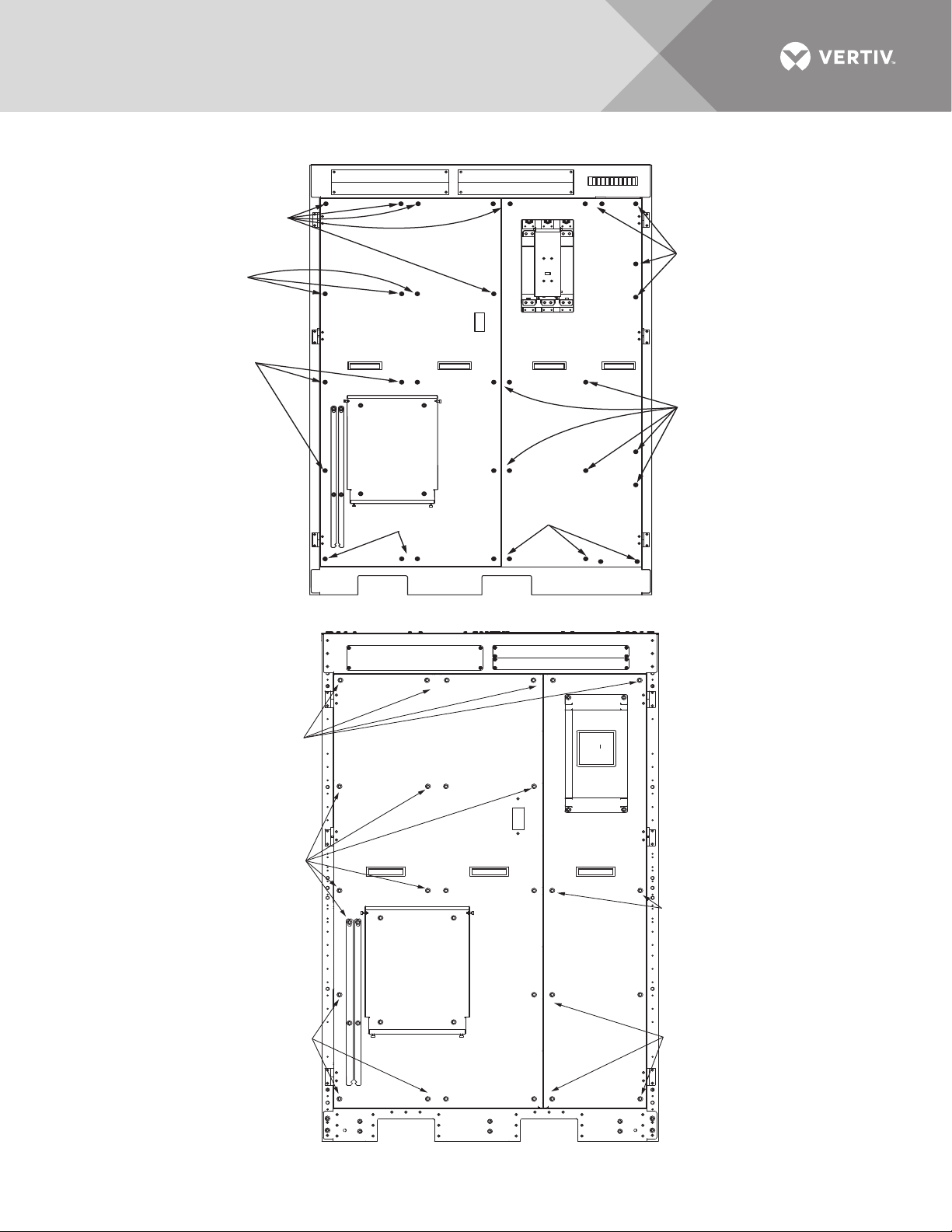
Figure 1 Shipping bolts—Top-terminal battery cabinet, standard width
Outer doors
not shown.
Shipping Bolts
Shipping
Bolts
Shipping
Bolts
Shipping
Bolts
Shipping
Bolts
Shipping
Bolts
Shipping
Bolts
Figure 2 Shipping bolts—Top-terminal battery cabinet, reduced width
Shipping
Bolts
Shipping
Bolts
Shipping
Bolts
Shipping
Bolts
Shipping
Bolts
Outer doors
not shown
Vertiv | Liebert® Large System Installation Manual | 7

1.4.2 Clearances
The Liebert® battery system has no ventilation grilles at either side or at the rear of the battery
system equipment. It is important to leave a distance of 24" (610mm) between the top of the
cabinet and the ceiling of the room where it is installed to permit adequate circulation of air
coming out of the unit and for service access.
Clearance around the front of the equipment should be sufficient to enable free passage of
personnel with the doors fully opened.
1.4.3 Raised Floor Mounting
If the equipment is to be placed on a raised floor, it should be mounted on a pedestal suitably
designed to accept the equipment point loading. Refer to the base view to design this pedestal.
1.5 System Composition
A battery system can consist of a number of equipment cabinets, depending on the individual
system design requirements, e.g., Battery Cabinet, Junction Cabinet. Refer to 3.0 -
INSTALLATION DRAWINGS for the positioning of the cabinets described below.
NOTE
A junction cabinet is required for Liebert® NXL™ units rated 500kVA and above except for standalone individual battery systems.
Vertiv | Liebert® Large System Installation Manual | 8

2.0 BATTERY INSTALLATION
2.1 Safety
Special care should be taken when working with the batteries associated with the Liebert®
battery system equipment. When all the cells are connected together, the battery terminal
voltage will exceed 400V and is potentially lethal. A primary safety consideration is to install the
battery equipment in an isolated area, accessible only to properly trained and qualified
maintenance personnel.
WARNING
Risk of electric shock. Can cause equipment damage, personal injury and death.
Hazardous battery voltage present behind covers. No user-serviceable parts are located
behind covers that require a tool for removal. Only properly trained and qualified service
personnel are authorized to remove such covers or perform installation or maintenance.
The following general battery safety precautions and warnings must be observed at all
times:
• A battery can present risk of electric shock or burn from high short circuit currents.
• When connected in a string, the voltage will exceed 400VDC. This voltage is
potentially lethal. Always observe high-voltage precautions.
• Eye protection must be worn to prevent injury from accidental electrical arcs.
• Remove rings, watches, necklaces, bracelets and all other metal objects.
• Use only tools with insulated handles.
• Wear appropriate personal protective equipment when handling batteries.
• If a battery leaks electrolyte or is otherwise physically damaged, it should be placed in
a container resistant to wire and disposed of in accordance with local regulations.
• If electrolyte comes into contact with skin, the affected area should be washed
immediately with plenty of clean water.
• Batteries must always be disposed of according to local environmental laws.
• When replacing batteries, use the same number and type that were originally fitted.
• Disconnect charging source prior to connecting or disconnecting battery terminals.
• Determine if the battery is grounded. If it is grounded, remove source of ground.
Contact with any part of a grounded battery can result in electrical shock.
• Battery support tray must be used whenever a battery tray is being pulled out.
Vertiv | Liebert® Large System Installation Manual | 9
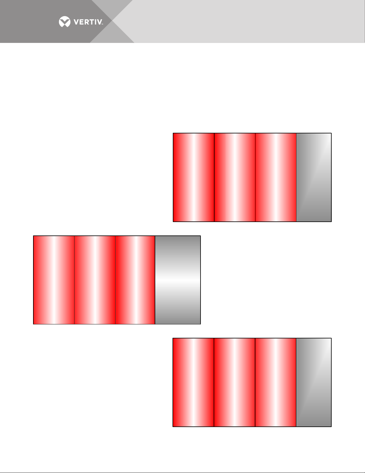
2.2 Layout
47"
(1194mm)
Battery
Cabinet
47"
(1194mm)
Battery
Cabinet
47"
(1194mm)
Battery
Cabinet
15-½"
Junction
Cabinet
(May be on
either end
or betw een
any battery
cabinets)
625-750kVA
Stand-Alone
Interconnected
Systems
47"
(1194mm)
Battery
Cabinet
47"
(1194mm)
Battery
Cabinet
47"
(1194mm)
Battery
Cabinet
S
p
a
c
e
r
Liebert
UPS
625-1200kVA
One or more battery
cabinets bolted to the UPS.
Battery cabinets must be on
the left side of the UPS.
47"
(1194mm)
Battery
Cabinet
47"
(1194mm)
Battery
Cabinet
47"
(1194mm)
Battery
Cabinet
17-½"
Junction
Cabinet
(May be on
either end
or betw een
any battery
cabinets )
800-1200kVA
Stand-Alone
Interconnected
Systems
Depending on the site layout, the battery cabinets can be installed in any of several ways:
• Connected to Module—One or more battery cabinets bolted to the UPS
• Stand-Alone Individual Cabinets—Single battery cabinets not bolted to the UPS
• Stand-Alone Interconnected Cabinets—Multiple battery cabinets not bolted to the UPS
See Figures 3 through 8 for top terminal battery cabinets.
See Figures 9 through 14 for front terminal battery cabinets.
Figure 3 Top-terminal battery system configurations—Liebert® EXL™
Vertiv | Liebert® Large System Installation Manual | 10
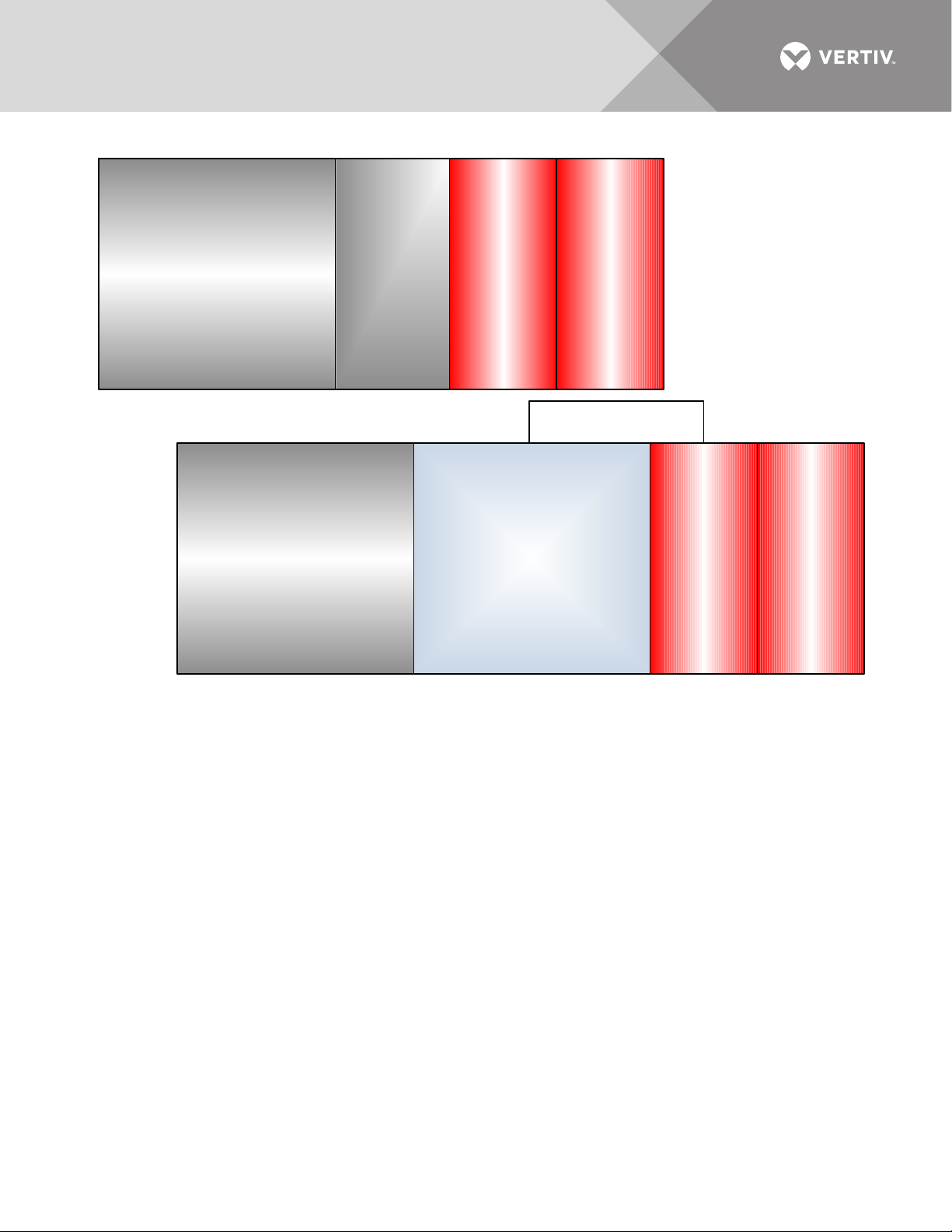
Figure 4 Top-terminal battery system configurations attached to UPS—Liebert® EXL™ S1
Liebert
UPS
47"
(1194mm)
Battery
Cabinet
47"
(1194mm)
Battery
Cabinet
Standard
Input/
Output
Cabinet
47"
(1194 mm)
Battery
Cabinet
47"
(1194 mm)
Battery
Cabinet
Liebert
UPS
Busbar Shroud
Input/Output Cabinet
Any Combination of
Back-Feed Disconnect ,
Sharing Inductor and
Common Mode Choke
Vertiv | Liebert® Large System Installation Manual | 11
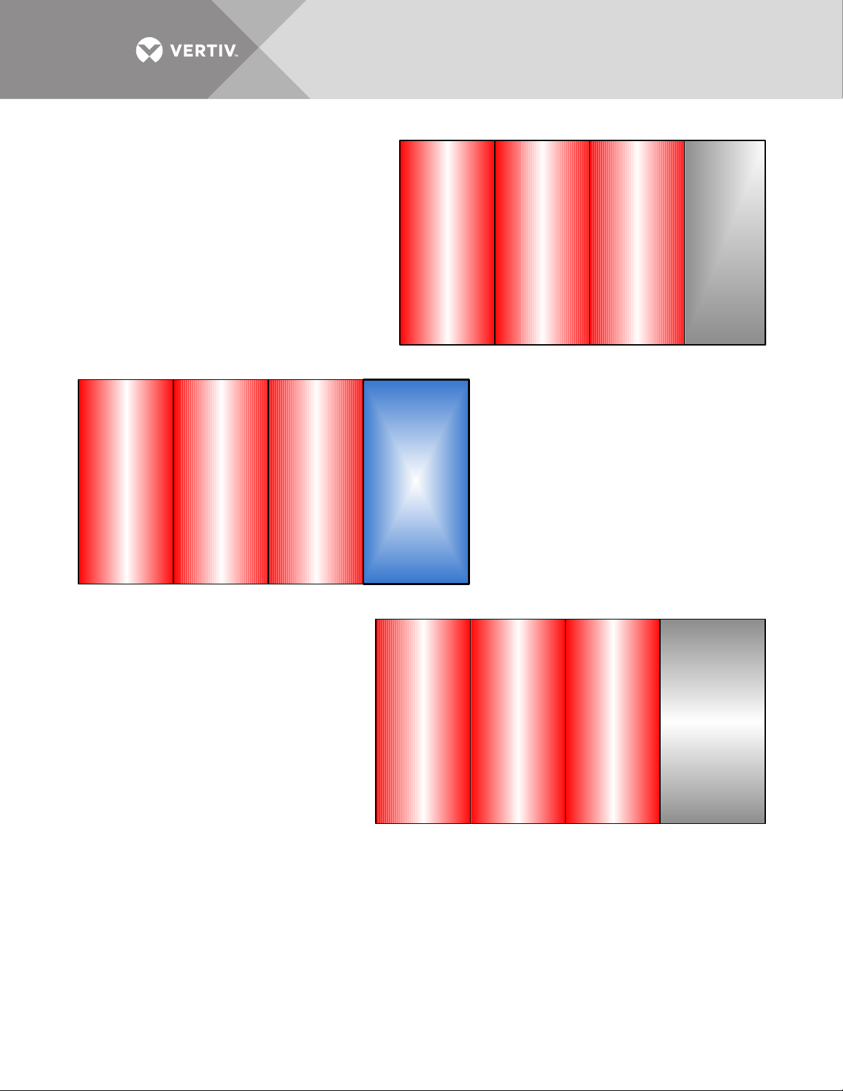
Figure 5 Top-terminal battery system configurations—Liebert® NX™ 225-600kVA
500-600kVA
Stand-Alone
Interconnected
47"
(1194mm)
Battery
Cabinet
47"
(1194mm)
Battery
Cabinet
47"
(1194mm)
Battery
Cabinet
15-½"
Junction
Cabinet
(May be on
either end
or betw een
any battery
cabinets)
225-400kVA
Stand-Alone
Interconnected
47"
(1194mm)
Battery
Cabinet
47"
(1194mm)
Battery
Cabinet
47"
(1194mm)
Battery
Cabinet
55"
(1397mm)
Battery
Cabinet
47"
(1194mm)
Battery
Cabinet
47"
(1194mm)
Battery
Cabinet
47"
(1194mm)
Battery
Cabinet
Liebert
UPS
225-600kVA
One or more battery
cabinets bolted to the UPS
Battery cabinets must be on
the left side of the UPS.
Vertiv | Liebert® Large System Installation Manual | 12
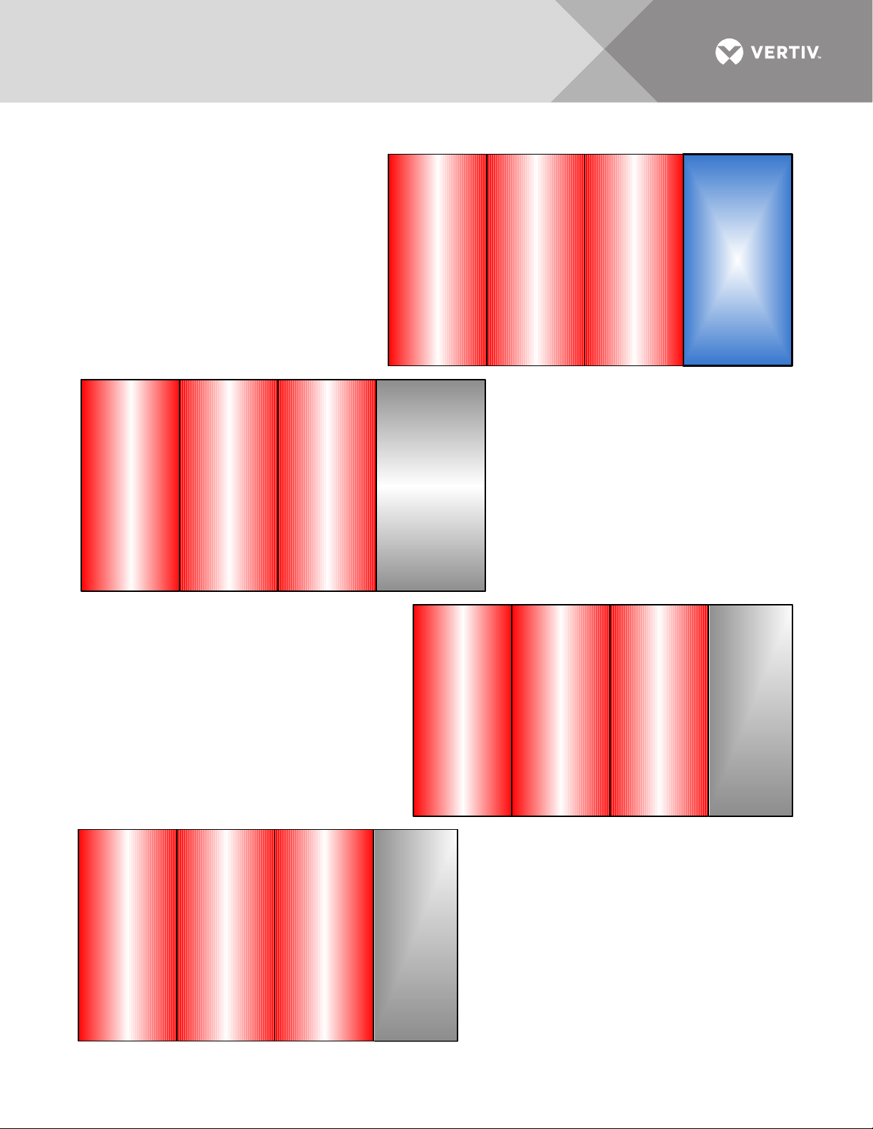
Figure 6 Top-terminal battery system configurations—Liebert® NXL™
250-400kVA
Stand-Alone
Interconnected Systems
55" battery cabinet must
be on the right side of the
47" (1194mm) cabinets.
47"
(1194mm)
Battery
Cabinet
47"
(1194mm)
Battery
Cabinet
47"
(1194mm)
Battery
Cabinet
55"
(1397mm)
Battery
Cabinet
47"
(1194mm)
Battery
Cabinet
47"
(1194mm)
Battery
Cabinet
47"
(1194mm)
Battery
Cabinet
Liebert
UPS
47"
(1194mm)
Battery
Cabinet
47"
(1194mm)
Battery
Cabinet
47"
(1194mm)
Battery
Cabinet
15-½"
Junction
Cabinet
(May be on
either end
or betw een
any battery
cabinets )
500-750kVA
Stand-Alone
Interconnected
Systems
47"
(1194mm)
Battery
Cabinet
47"
(1194mm)
Battery
Cabinet
47"
(1194mm)
Battery
Cabinet
17-½"
Junction
Cabinet
(May be on
either end
or betw een
any battery
cabinets )
800-1100kVA
Stand-Alone
Connected
Systems
250-750kVA
One or more battery cabinets bolted to
the UPS
Battery cabinets may be on either side of
a 250-300kVA UPS and 400kVA 480V
UPS. Battery cabinets must be on the left
side of a 500-750kVA UPS.
Battery cabinets must be on the left side
Vertiv | Liebert® Large System Installation Manual | 13
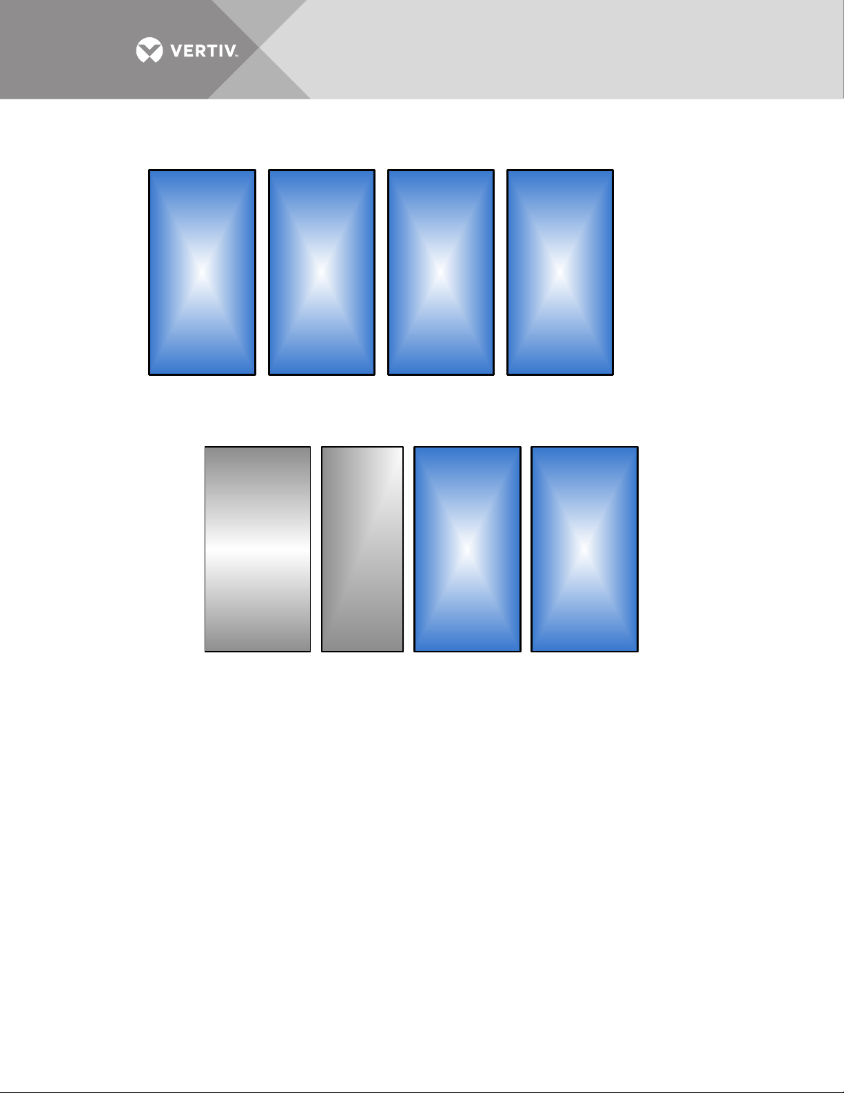
Figure 7 Top-terminal stand-alone battery system configuration—Liebert® EXL™, Liebert® EXL™ S1,
55"
(1397mm)
Battery
Cabinet
55"
(1397mm)
Battery
Cabinet
55"
(1397mm)
Battery
Cabinet
55"
(1397mm)
Battery
Cabinet
Stand-Alone
Individual
Liebert
UPS
Detached
Junction
Cabinet
32"
(813mm)
55"
(1397mm)
Battery
Cabinet
55"
(1397mm)
Battery
Cabinet
Stand-Alone
Individual
Liebert® NX™ and Liebert® NXL™, all ratings
Figure 8 Top-terminal battery system configuration—Battery cabinets not attached to UPS or each other,
Liebert® EXL™, Liebert® EXL™ S1, Liebert® NX™ and Liebert® NXL™
Vertiv | Liebert® Large System Installation Manual | 14
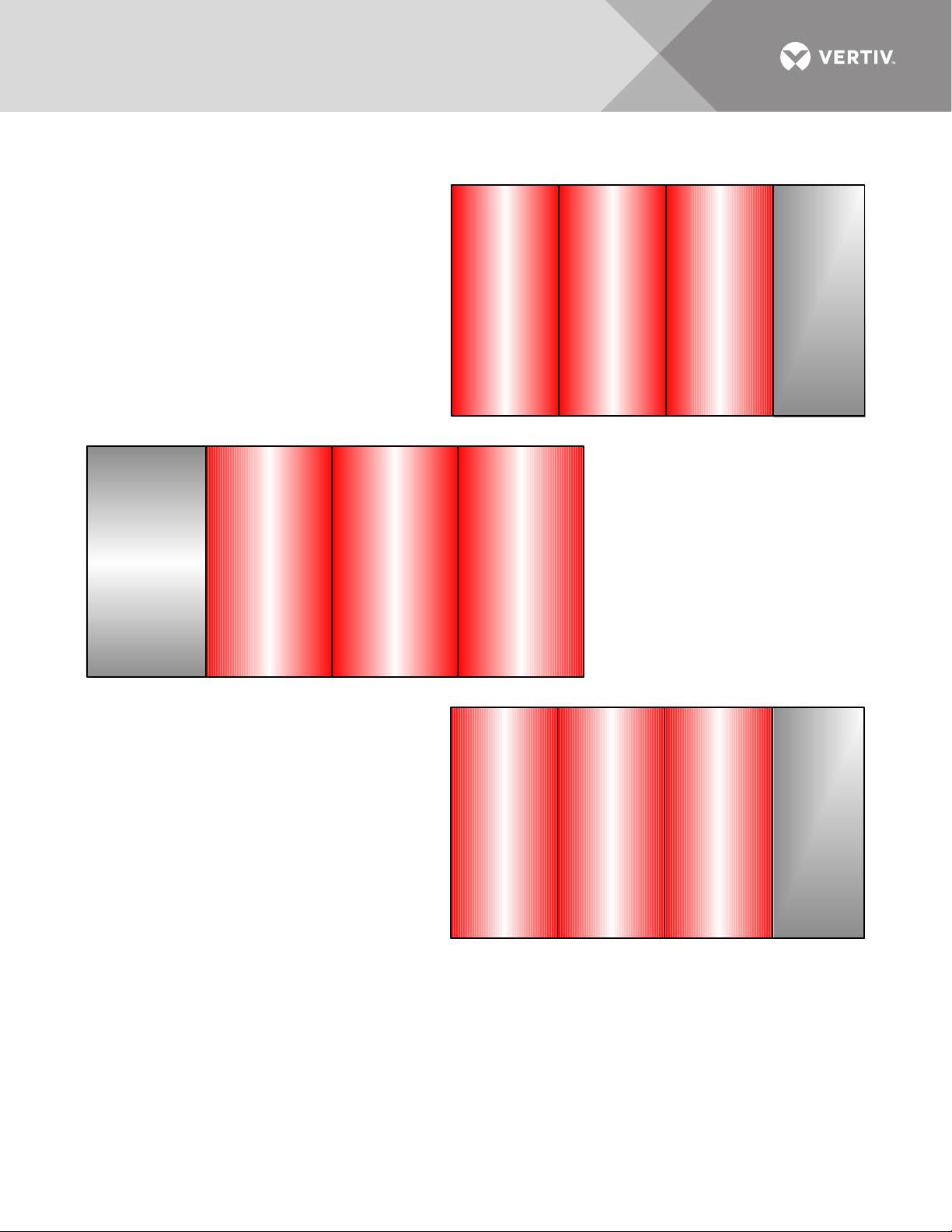
Figure 9 Front-terminal battery system configurations—Liebert® EXL™
62"
(1575mm)
Battery
Cabinet
62"
(1575mm)
Battery
Cabinet
62"
(1575mm)
Battery
Cabinet
15-½"
Junction
Cabinet
(May be on
either end
or betw een
any battery
cabinets)
625-750kVA
Stand-Alone
Interconnected
Systems
625-1200kVA
One or more battery
cabinets bolted to the UPS
Battery cabinets must be
on the left side of the UPS.
62"
(1575mm)
Battery
Cabinet
62"
(1575mm)
Battery
Cabinet
62"
(1575mm)
Battery
Cabinet
17-½"
Junction
Cabinet
(May be on
either end
or between
any battery
cabinets )
800-1200kVA
Stand-Alone
Interconnected
Systems
Liebert
UPS
61.6"
(1565 mm)
Battery
Cabinet
61.6"
(1565mm)
Battery
Cabinet
61.6"
(1565mm)
Battery
Cabinet
Vertiv | Liebert® Large System Installation Manual | 15
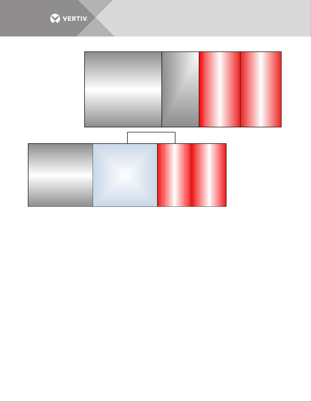
Figure 10 Front-terminal battery system configurations attached to UPS—Liebert® EXL™ S1
Standard
Input/
Output
Cabinet
Liebert
UPS
62"
(1575 mm)
Battery
Cabinet
62"
(1575mm)
Battery
Cabinet
Liebert
UPS
62"
(1575 mm)
Battery
Cabinet
62"
(1575 mm)
Battery
Cabinet
Busbar Shroud
Input/Output Cabinet
Any Combination of
Back-Feed Disconnect ,
Sharing Inductor and
Common Mode Choke
Vertiv | Liebert® Large System Installation Manual | 16
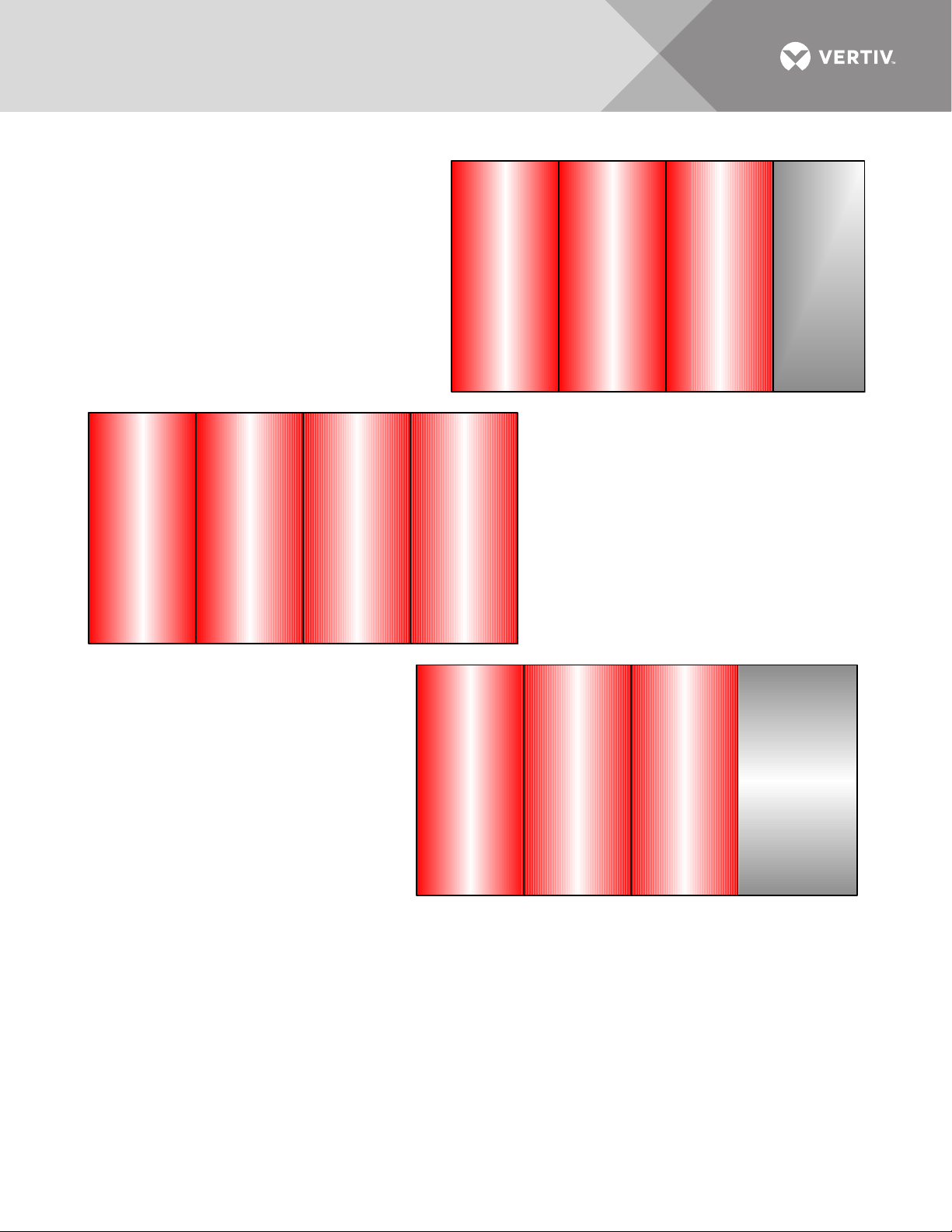
Figure 11 Front-terminal battery system configurations—Liebert® NX™
500-600kVA
Stand-Alone
Interconnect
ed Systems
62"
(1575mm)
Battery
Cabinet
62"
(1575mm)
Battery
Cabinet
62"
(1575mm)
Battery
Cabinet
15-½"
Junction
Cabinet
(May be on
either end
or betw een
any battery
cabinets)
225-400kVA
Stand-Alone
Interconnected
Systems
62"
(1575mm)
Battery
Cabinet
62"
(1575mm)
Battery
Cabinet
62"
(1575mm)
Battery
Cabinet
62"
(1575mm)
Battery
Cabinet
62"
(1575mm)
Battery
Cabinet
62"
(1575mm)
Battery
Cabinet
62"
(1575mm)
Battery
Cabinet
Liebert
UPS
225-600kVA
One or more battery
cabinets bolted to the UPS
Battery cabinets must be on
left side of UPS.
Vertiv | Liebert® Large System Installation Manual | 17
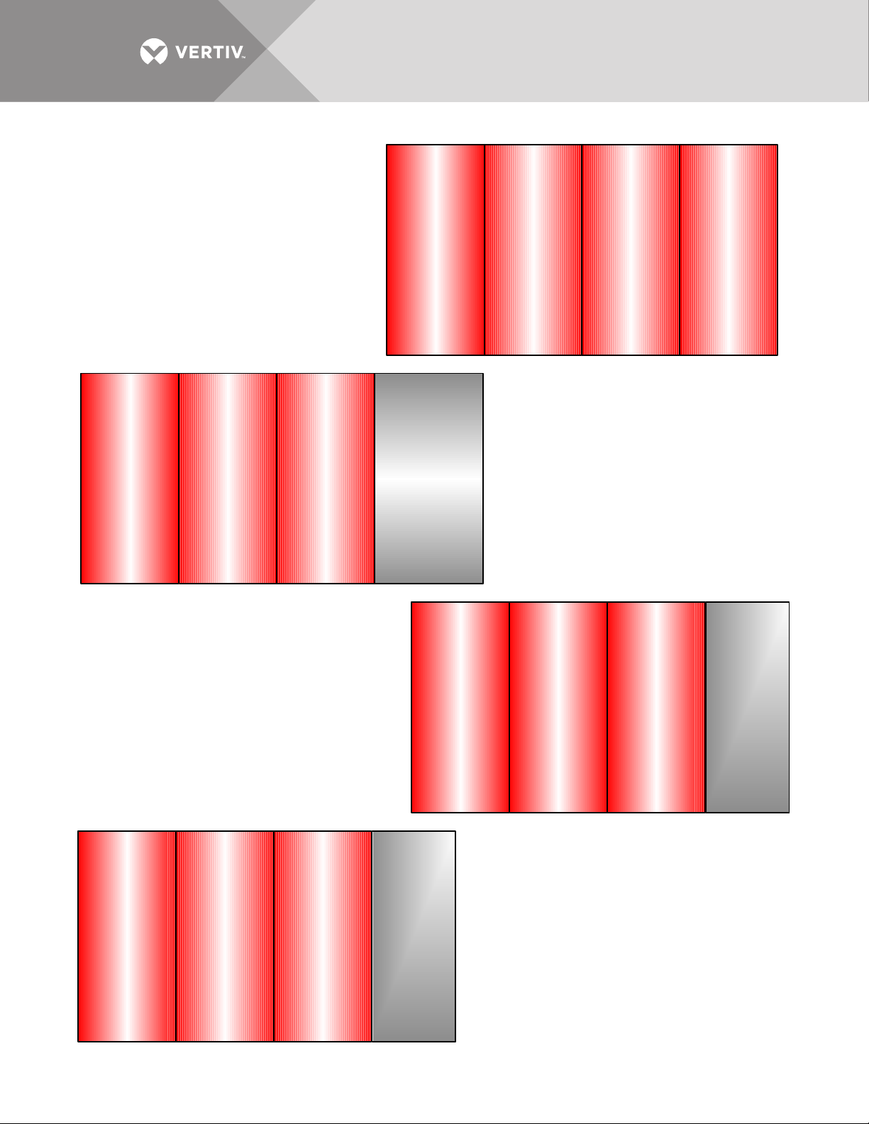
Figure 12 Front-terminal battery system configurations—Liebert® NXL™
250-400kVA
Stand-Alone
Interconnect
ed Systems
62"
(1575mm)
Battery
Cabinet
62"
(1575mm)
Battery
Cabinet
62"
(1575mm)
Battery
Cabinet
62"
(1575mm)
Battery
Cabinet
62"
(1575mm)
Battery
Cabinet
62"
(1575mm)
Battery
Cabinet
62"
(1575mm)
Battery
Cabinet
Liebert
UPS
62"
(1575mm)
Battery
Cabinet
62"
(1575mm)
Battery
Cabinet
62"
(1575mm)
Battery
Cabinet
15-½"
Junction
Cabinet
(May be on
either end
or between
any battery
cabinets )
500-750kVA
Stand-Alone
Interconnected
62"
(1575mm)
Battery
Cabinet
62"
(1575mm)
Battery
Cabinet
62"
(1575mm)
Battery
Cabinet
17-½"
Junction
Cabinet
(May be on
either end
or between
any battery
cabinets )
800-1100kVA
Connected
Stand-Alone
250-750kVA
One or more battery cabinets bolted to
the UPS
Battery cabinets may be on either side of
250-300kVA UPS and 400kVA 480V
UPS. Battery cabinets must be on the left
side of a 500-750kVA UPS.
Battery cabinets must be on the left side
Vertiv | Liebert® Large System Installation Manual | 18
 Loading...