

Page 1

Liebert®
DSE™ PackagedSolution
ThermalManagementSystem
Installer/User Guide
60-kW (15-ton)Capacity
Page 2
The information contained in this document is subject to change
without notice and may not be suitable for all applications. While
every precaution has been taken to ensure the accuracy and
completeness of this document, Vertiv assumes no responsibility
and disclaims all liability for damages resulting from use of this
information or for any errors or omissions. Refer to other local
practices or building codes as applicable for the correct methods,
tools, and materials to be used in performing procedures not
specifically described in this document.
The products covered by this instruction manual are manufactured
and/or sold by Vertiv. This document is the property of Vertiv and
contains confidential and proprietary information owned by Vertiv.
Any copying, use or disclosure of it without the written permission
of Vertiv is strictly prohibited.
Names of companies and products are trademarks or registered
trademarks of the respective companies. Any questions regarding
usage of trademark names should be directed to the original
manufacturer.
Technical Support Site
If you encounter any installation or operational issues with your product, check the pertinent
section of this manual to see if the issue can be resolved by following outlined procedures.
Visit https://www.VertivCo.com/en-us/support/ for additional assistance.
Vertiv |Liebert® DSE060™Installer/User Guide
Page 3

TABLE OF CONTENTS
1 Important Safety Instructions 5
2 Nomenclature and Components 9
2.1 Liebert DSE060 Packaged Solution Configuration-number Nomenclature 9
2.2 Component Location 12
2.3 Air-flow Configurations 12
3 Pre-installation PreparationandGuidelines 13
3.1 Planning Dimensions 14
3.2 Connections and System Setup 14
3.2.1 Electrical Connections 14
3.2.2 Evaporator Condensate-drain Connection 14
3.3 Operating Conditions 16
3.3.1 Cooling 17
3.4 Unit Weights 17
4 Equipment Inspection and Handling 19
4.1 Rigging to Lift the Unit 20
4.2 Using Forklift to Install the Unpackaged Unit 21
5 Electrical Field Connections 23
6 Checklist for Completed Installation 27
6.1 Moving and Placing Equipment 27
6.2 Electrical Installation Checks 27
6.3 Other Installation Checks 27
6.4 BMS and Sensor Installation Checks 28
7 Initial Start-up Checks andCommissioningProcedure forWarrantyInspection 29
8 Maintenance 31
8.1 Service/Maintenance Access to the Evaporator Compartment 32
8.2 Filters 32
8.2.1 Filter-replacement 32
8.3 Evaporator Blower Drive System—EC Fans 34
8.3.1 Protective Features 34
8.3.2 Fan Impellers and Bearings Maintenance 35
8.3.3 Fan Assembly Troubleshooting 35
8.3.4 Removing Evaporator EC Fans 39
8.4 Electronic Expansion Valve (EEV) Maintenance 41
8.5 Compressor Maintenance 42
8.5.1 Compressor Oil 42
8.5.2 Rotalock Valve 42
8.5.3 Replacement Compressors 43
8.5.4 Compressor Motor Burnout 43
8.5.5 Unloading Solenoid(s) on a Digital-scroll Compressor 43
8.5.6 Replacing the Compressor 43
Vertiv | Liebert® DSE060™ Installer/User Guide | 3
Page 4

8.6 Evaporator Coil 44
8.7 General Condenser Maintenance 44
8.8 Condenser Cleaning 44
8.8.1 When to Clean the Condenser Coil 44
8.8.2 What to Use to Clean the Condenser Coil 45
8.8.3 Cleaning the Condenser Coil 45
8.8.4 Cleaning the Condenser Fan 46
8.9 Replacing the Condenser Fan 46
8.9.1 Verifing the Fan Address 53
8.10 Replacing the Premium-efficiency Control Board 57
8.10.1 Preparing to Replace the Board 57
8.10.2 Installing the Replacement Board 59
8.11 Pumped-refrigerant Economizer (PRE) 60
9 Preventive Maintenance Checklist 61
Appendices 67
Appendix A: Technical Support and Contacts 67
Appendix B: Submittal Drawings 69
Vertiv | Liebert® DSE060™ Installer/User Guide | 4
Page 5
1 IMPORTANT SAFETY INSTRUCTIONS
SAVE THESE INSTRUCTIONS
This manual contains important safety instructions that should be followed during the installation and
maintenance of the Liebert®DP060. Read this manual thoroughly before attempting to install or operate
this unit.
Only qualified personnel should move, install or service this equipment.
Adhere to all warnings, cautions, notices and installation, operating and safety instructions on the unit
and in this manual. Follow all installation, operation and maintenance instructions and all applicable
national and local building, electrical and plumbing codes.
WARNING! Arc flash and electric shock hazard. Open all local and remote electric power-supply
disconnect switches, verify with a voltmeter that power is Off and wear appropriate,
OSHA-approved personal protective equipment (PPE) per NFPA 70E before working within the
electric control enclosure. Failure to comply can cause serious injury or death. Customer must
provide earth ground to unit, per NEC, CEC and local codes, as applicable. Before proceeding
with installation, read all instructions, verify that all the parts are included and check the
nameplate to be sure the voltage matches available utility power. The Liebert® controller does
not isolate power from the unit, even in the “Unit Off” mode. Some internal components require
and receive power even during the “Unit Off” mode of the controller. The factory-supplied
disconnect switch is on the exterior of the enclosure. The only way to ensure that there is NO
voltage inside the unit is to install and open a remote disconnect switch. Refer to unit electrical
schematic. Follow all local codes.
WARNING! Risk of electric shock. Can cause equipment damage, injury or death. Open all local
and remote electric power supply disconnect switches and verify with a voltmeter that power is
off before working within any electric connection enclosures. Service and maintenance work
must be performed only by properly trained and qualified personnel and in accordance with
applicable regulations and manufacturers’ specifications. Opening or removing the covers to
any equipment may expose personnel to lethal voltages within the unit even when it is
apparently not operating and the input wiring is disconnected from the electrical source.
WARNING! Risk of electric shock. Can cause serious injury or death. Open all local and remote
electric power supply disconnect switches and verify with a voltmeter that power is off before
working within the component electric-connection enclosures. Fan-motor controls can
maintain an electric charge for 10 minutes after power is disconnected. Wait 10 minutes after
power is verified as off before working within the fan electric control/connection enclosures.
1 Important Safety Instructions
5
Page 6
WARNING! Risk of over-pressurization of the refrigeration system. Can cause explosive
discharge of high-pressure refrigerant, loss of refrigerant, environmental pollution, equipment
damage, injury, or death. This unit contains fluids and gases under high pressure. Use extreme
caution when charging the refrigerant system. Do not pressurize the system higher than the
design pressure marked on the unit's nameplate.
WARNING! Risk of pressurized doors flying open or slamming closed suddenly. Can cause
serious injury. Do not attempt to open doors while fans are running. Do not turn on fans with
doors open. Before opening the door, open all local and remote electric power supply
disconnect switches, verify with a voltmeter that power is off, and verify that all fans have
stopped rotating. Do not leave unsecured objects in the fan's bay after any maintenance
operation.
WARNING! Risk of contact with flying objects. Can cause serious injury or death. Do not leave
unsecured objects or tools in the fan's bay after performing maintenance operations. Re-install
all panels before starting up this unit after maintenance is performed.
WARNING! Risk of very heavy, 250-lb (113.4-kg) condenser fan modules and 125-lb (57-kg)
evaporator fan modules dropping downward suddenly. Can cause injury or death.
Support fan modules before removing mounting hardware. Use caution to keep body parts out
of the fan modules pathway during repositioning. Only properly trained and qualified personnel
should work on this equipment.
WARNING! Risk of improper moving. Can cause equipment damage, injury or death. Use only
lifting equipment that is rated for the unit weight by an OSHA-certified rating organization. The
center of gravity varies depending on the unit size and selected options. The slings must be
equally spaced on either side of the center of gravity indicator.
Unit weights are listed in Table 3.3 on page17. Use the center of gravity indicators on the unit
to determine the position of the slings.
WARNING! Risk of contact with high-speed rotating fan blades. Can cause serious injury or
death. Open all local and remote electric power-supply disconnect switches, verify with a
voltmeter that power is off, and verify that all fan blades have stopped rotating before working
in the unit cabinet or on the fan assembly. If control voltage is applied, the fan motor can restart
without warning after a power failure.
WARNING! Risk of improper wiring, piping, moving, lifting and handling. Can cause equipment
damage, serious injury or death. Installation and service of this equipment should be done only
by qualified personnel who have been specially-trained in the installation of air-conditioning
equipment and who are wearing appropriate, OSHA-approved PPE.
6
Vertiv | Liebert® DSE060™ Installer/User G uide
Page 7
WARNING! Risk of improper wire sizing/rating and loose electrical connections. Can cause
overheated wire and electrical connection terminals resulting in smoke, fire, equipment and
building damage, injury or death. Use correctly sized copper wire only and verify that all
electrical connections are tight before turning power On. Check all electrical connections
periodically and tighten as necessary.
CAUTION: Risk of contact with sharp edges, splinters, and exposed fasteners. Can cause
injury. Only properly trained and qualified personnel wearing appropriate, OSHA-approved PPE
should attempt to move, lift, remove packaging from or prepare the unit for installation.
CAUTION: Risk of contact with hot surfaces. Can cause injury. The compressor, refrigerant
discharge lines, fan motor, and some electrical components are extremely hot during unit
operation. Allow sufficient time for them to cool to a touch-safe temperature before working
within the unit cabinet. Use extreme caution and wear appropriate, OSHA-approved PPE when
working on or near hot components.
CAUTION: Risk of contact with hot surfaces. Can cause burn injury. The EC fans and
electronics housing are extremely hot during operation. Allow sufficient time for them to cool
to a touch-safe temperature before handling. Use extreme caution and wear appropriate,
OSHA-approved PPE when replacing or performing maintenance on the EC fans.
CAUTION: Risk of improper moving, lifting and handling. Can cause equipment damage or
injury. Only properly trained and qualified personnel should work on this equipment. Fan
modules weigh in excess of weigh in excess of 125lb (57kg). Use proper lifting techniques and
wear appropriate, OSHA-approved PPE to avoid injury and dropping the fan module during
removal. Equipment used in handling/lifting, and/or installing the fan assembly must meet
OSHA requirements. Use handling/lifting equipment rated for the weight of the fan assembly.
Use ladders rated for the weight of the fan assembly and technicians if used during installation.
Refer to handling/lifting, and/or installation equipment operating manual for manufacturer's
safety requirements and operating procedures.
CAUTION: Risk of exposure to harmful noise levels. Can cause hearing injury or loss.
Depending on the installation and operating conditions, a sound pressure level greater than
70dB(A) may arise. Take appropriate technical safety measures. Operating personnel must
wear appropriate, OSHA-approved PPE and observe all appropriate hearing-protection safety
requirements.
1 Important Safety Instructions
7
Page 8

NOTICE
NOTICE
NOTICE
Risk of improper power-supply connection. Can cause equipment damage and loss of warranty
coverage.
Prior to connecting any equipment to a main or alternate power source (for example: back-up
generator systems) for start-up, commissioning, testing, or normal operation, ensure that these
sources are correctly adjusted to the nameplate voltage and frequency of all equipment to be
connected. In general, power-source voltages should be stabilized and regulated to within
±10% of the load nameplate nominal voltage. Also, ensure that no three-phase sources are
single-phased at any time.
Risk of oil contamination with water. Can cause equipment damage.
Liebert®DP060 systems require the use of POE (polyolester) oil. POE oil absorbs water at a
much faster rate when exposed to air than previously used oils. Because water is the enemy of
a reliable refrigeration system, extreme care must be used when opening systems during
service. If water is absorbed into the POE oil, it will not be easily removed and will not be
removed through the normal evacuation process. If the oil is too wet, it may require an oil
change. POE oils also have a property that makes them act as a solvent in a refrigeration
system. Maintaining system cleanliness is extremely important because the oil will tend to
bring any foreign matter back to the compressor.
Risk of improper operation in high-humidity conditions. Can cause unit damage and water
carryover.
The Liebert® DP060 operates only as a sensible cooling unit and does not provide
dehumidification.
NOTE: The Liebert® cooling unit has a factory-installed high pressure safety switch in the high-side
refrigerant circuit.
Agency Listed
Standard 60-Hz units are CSA Certified to the harmonized U.S. and Canadian product safety standard
CSA C22.2 No 236/UL 1995 for “Heating and Cooling Equipment” and are marked with the CSA c-us logo.
8
Vertiv | Liebert® DSE060™ Installer/User G uide
Page 9
2 NOMENCLATURE AND COMPONENTS
This section describes the configuration number for Liebert® DP060 units and components.
2.1 Liebert DSE060 Packaged Solution Configuration-number Nomenclature
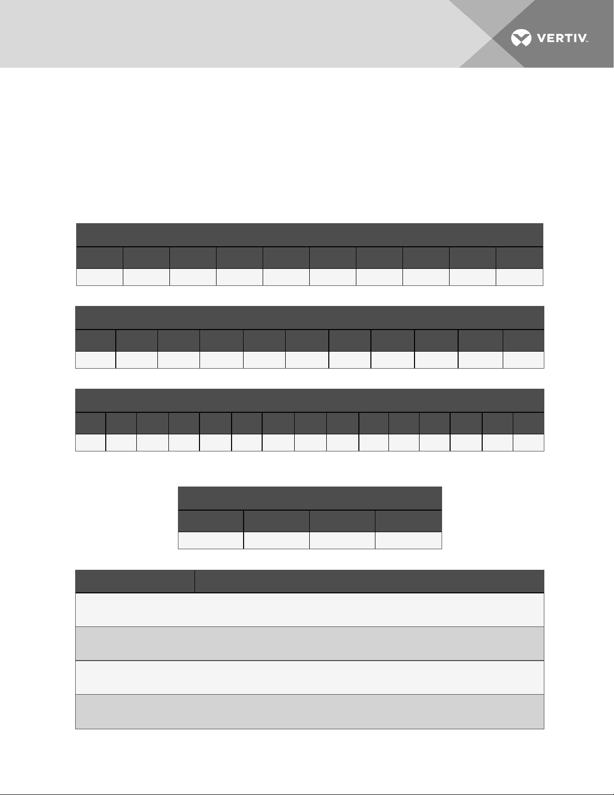
The following tables describe each digit of the 40-digit DP060 configuration number. The 14-digit model
number consists of the first 10 digits and last 4 digits of the configuration number.
Table 2.1 DSE060 Configuration-number Digits 1 to 10 Example
Configuration -number Digits 1 to 10 = first 1 0 digits of 14-digit model number
1 2 3 4 5 6 7 8 9 10
D P 0 6 0 T P 1 A D
Table 2.2 DSE060 Configuration-number Detail Digits 11 to 21 Example
Configuration-number Detail Digits 1 1 to 21
11 12 13 14 15 16 17 18 19 20 21
0 2 0 8 1 6 L D B 0 P
Table 2.3 DSE060 Configuration-number Detail Digits 22 to 36 Example
Configuration-number Detail Digits 22 to 36
22 23 24 25 26 27 28 29 30 31 32 33 34 35 36
0 A A 1 0 0 0 0 0 0 0 0 0 0 0
Table 2.4 DSE060 Configuration-number
Digits37to40Example
Configuration -number Digits 37 to 40 = last 4 d igits of 14-digit model number
37 38 39 40
# # # A
Table 2.5 DSE060 Packaged Solution Configuration-number Digit Definitions
Digit Description
Digits 1 and 2 = Product Family
DP = Liebert® Packaged DSE
Digit 3 to 5 = Cooling Capacity, kW
Nominalsensible capacity, kW
Digit 6 = Air Discharge
T = Perimeter, top inlet/front supply
Digit 7 = System Type
P = Air-cooled, EconoPhase ready
2 Nomenclature and Components
9
Page 10
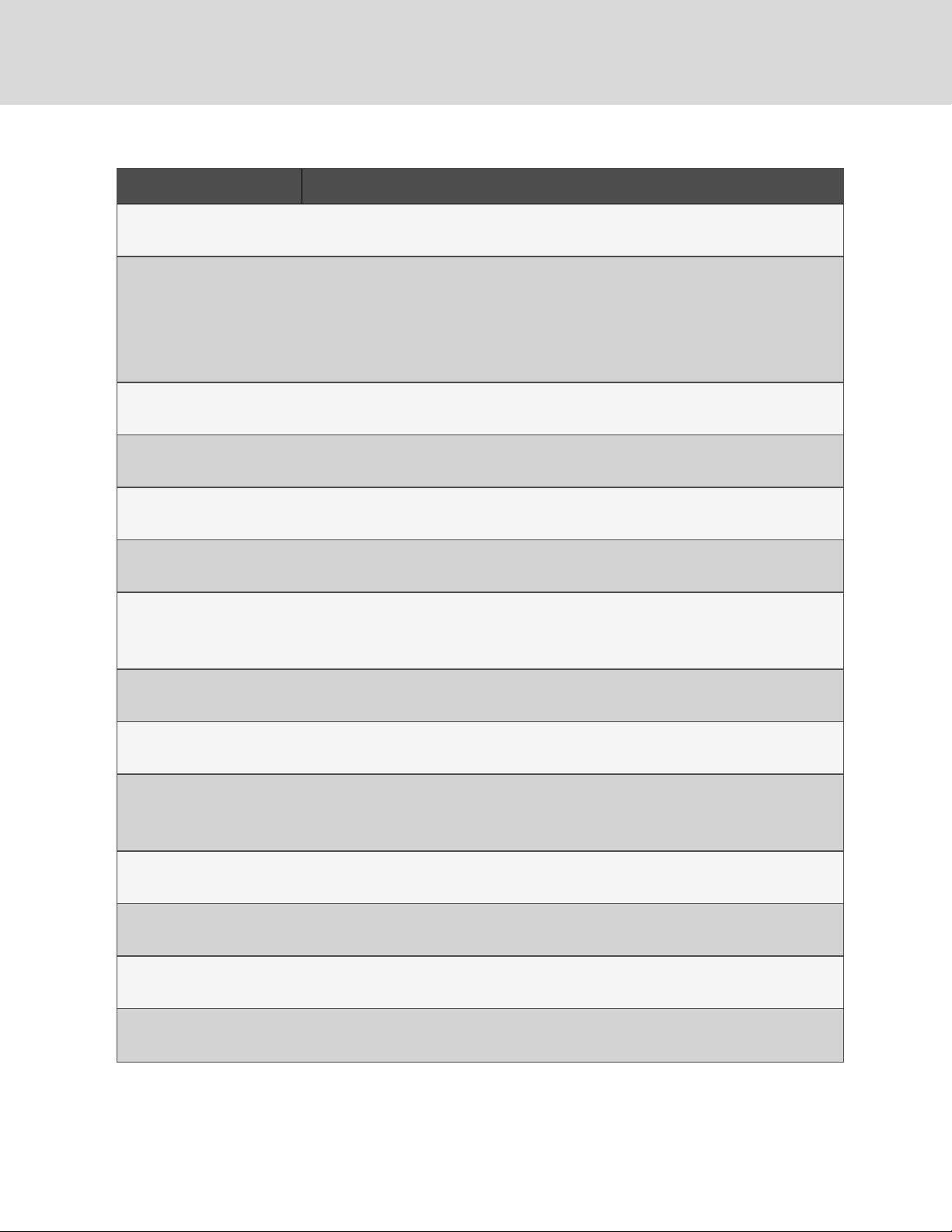
Table 2.5 DSE060 Packaged Solution Configuration-number Digit Definitions (continued)
Digit Description
Digit 8 = Air-flow (Fan Type)
1 = EC plug fans
Digit 9 = Power Supply
A = 460V/ 3ph / 60Hz
B = 575V / 3ph / 60Hz
C = 208V/ 3ph/ 60Hz
D = 230V / 3ph / 60Hz
Digit 10 = Cooling System
D = Digital scroll, R-410A
Digit 11 = Humidifier
0 = None
Digit 12 = Display
2 = Liebert® iCOM HighDefinition
Digit 13 = Options
0 = None
Digit 14 = Air Filter
8 = MERV 8, 4-in.
9 = MERV 11, 4-in.
Digit 15 = CoilOption
1 = Non-coated coils, evaporator and condenser
Digit 16 = Enclosure Option
6 = Standard color, pebble-gray
Digit 17 = High-voltage option
L = Locking disconnect
6 = Dual disconnect with reversing starter
Digit 18 = Option packages
D = Low-voltage terminal package + Remote humidifier contact
Digit 19 = Monitoring
B = Base Comms & Connectivity
Digit 2 0 = Sensors
0 = None
Digit 2 1 = Packaging
P = Domestic
10
Vertiv | Liebert® DSE060™ Installer/User G uide
Page 11
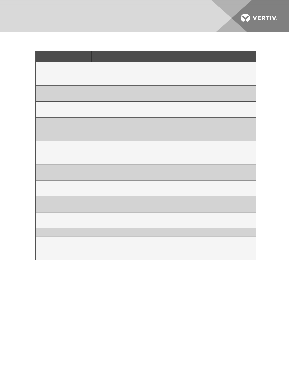
Table 2.5 DSE060 Packaged Solution Configuration-number Digit Definitions (continued)
Digit Description
Digit 2 2 = Controls
0 = None
S = Quick-start and Capacitive buffer (contact the factory)
Digit 2 3 =EconoPhase
A = Standard capacity
Digit 2 4 = Condenser Coil
A = Standard ambient condenser
Digit 2 5 = 120-V Options
1 = 120V Utility Power, Customer-supplied
T = 120-V utilitypower from main-unit power supply
Digit 2 6 = Option
0 = No power meter
P = Power meter (Contact the factory)
Digit 2 7 = Option
0 = None
Digit 2 8 = Option
0 = None
Digit 2 9 = Condensate Pump
0 = None
Digit 30 to 36
0 = Placeholder
Digit 37 to 39 = Factory Configuration Number
Digit 40 = Configuration Code
A = No SFA
S = SFA
2 Nomenclature and Components
11
Page 12
2.2 Component Location
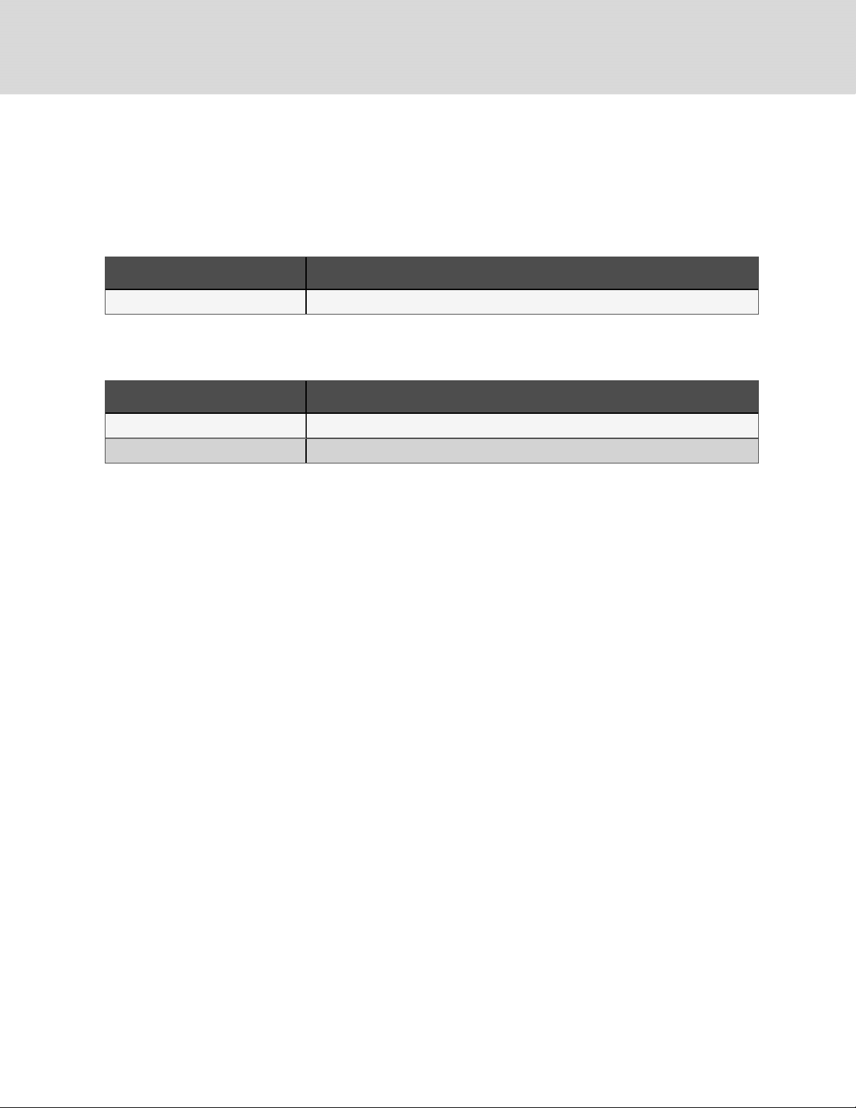
The unit component locations are described in the submittal documents included in the Submittal
Drawings on page69.
The following table lists the relevant documents by number and title.
Table 2.6 Component-location Drawings
Document Number Title
DPN004597 Component Location, Perimeter Unit
2.3 Air-flow Configurations
Table 2.7 Perimeter unit air-flow schematic and duct connection
Document Number Title
DPN004598 Airflow Schematic, Perimeter Unit
DPN004599 Evaporator Ducting DimensionalData
12
Vertiv | Liebert® DSE060™ Installer/User G uide
Page 13

3 PRE-INSTALLATION PREPARATIONANDGUIDELINES
NOTE: Before installing unit, determine whether any building alterations are required to run wiring and
ductwork. Follow all unit dimensional drawings and refer to the submittal engineering dimensional
drawings of individual units for proper clearances.
Refer to DSE060 Packaged Solution Configuration-number Digit Definitions (continued) on page11, and
submittal drawings to determine the type of system being installed and anticipate building alterations
and ductwork needed.
The unit and anchor dimensions are described in the submittal documents included in the Submittal
Drawings on page69.
• Verify that mounting surface/roof top is level, solid and sufficient to support the unit. See
DP060 unit weights on page17, for unit weights.
• Verify that the support structure for the unit (concrete or other type) has a flat, regular
surface and is adequate to support the unit operating weight.
• Verify that adequate water-control/drain system is in place per local code. Refer to the
appropriate submittal drawing, listed in Dimension Planning Drawings on the next page, for the
condensate drain-line location and connection size.
• Verify that the high-voltage electric-supply lines are adequately sized based on the electrical
specification on the unit's name plate and meet local code.
• Verify that the utility electric-supply lines (lights and outlet) are adequately sized and meet
local code.
• Verify that all control and communication wiring are properly routed to the unit control panel
and meet local code.
• Confirm that the conditioned space has a proper envelope and vapor barrier.
• Handle outside air and humidity control externally to the Liebert® DP060 unit. The DP060
does not control humidity and is not intended to handle outside air.
• Allow at least the minimum recommended clearances for maintenance and service. See the
appropriate submittal documents for dimensions in Submittal Drawings on page69
• Ensure that there is no obstruction when installing ductwork connections and transitions to
minimize friction losses and turbulence.
• Verify that all duct joints are sealed to prevent air leakage or water penetration.
3 Pre-installation PreparationandGuidelines
13
Page 14
3.1 Planning Dimensions
The unit and anchor dimensions are described in the submittal documents included in the Submittal
Drawings on page69.
The following table lists the relevant documents by number and title.
Table 3.1 Dimension Planning Drawings
Document Number Title
DPN004600 Cabinet and Anchor DimensionalData
DPN004599 Evaporator Ducting DimensionalData
DPN004601 Condensate-drain Access and Location
DPN004602 Evaporator Compartment Service Area
DPN004756 Installation andService Clearance for Multiple Units
3.2 Connections and System Setup
3.2.1 Electrical Connections
• Three-phase electrical service is required for all models. Electrical service must conform to
national and local electrical codes. See Electrical Field Connections on page23, for the details.
3.2.2 Evaporator Condensate-drain Connection
Connect the condensate-drain line to an adequate water-drain system. See 3.2 above, for the connection
on the unit. Observe the following requirements and Figure 3.2 on page16, when installing and routing
the drain line:
• Insulate the field-supplied condensate-drain piping with heat trace so it will not freeze.
• The line must be the full size of the drain connection. The connection port is 3/4-in. pipe with
CPVC 3/4-in. FPT fitting.
• Slope the drain line continuously away from the unit, and pitch the drain line a minimum of 1/8in. (3.2-mm) per 1ft (305mm) toward the drain.
• The line must be made of a material that is suitable for draining water and be rigid enough that
it does not sag between supports, which creates unintentional traps.
• The drain line must comply with all applicable codes.
14
Vertiv | Liebert® DSE060™ Installer/User G uide
Page 15
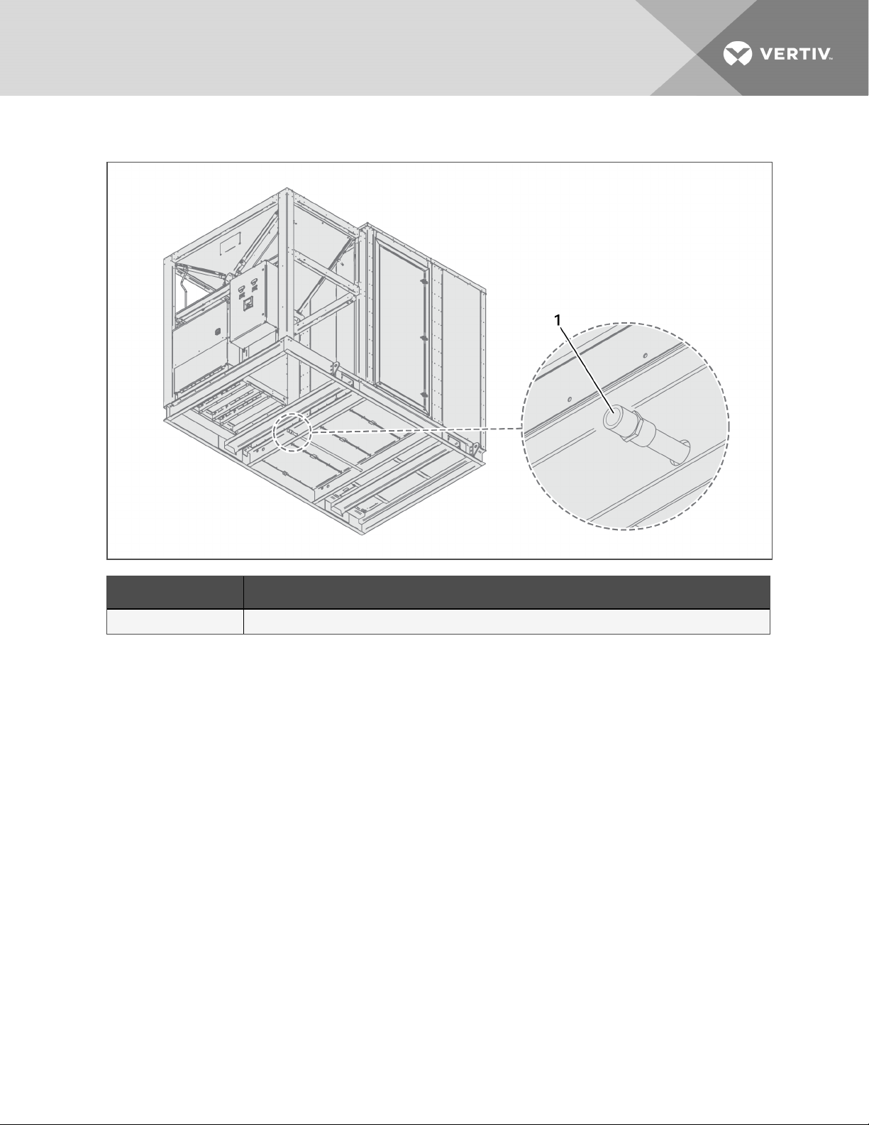
Figure 3.1 Condensate Drain Location
Item Description
1 Condensate-drain connection
3 Pre-installation PreparationandGuidelines
15
Page 16
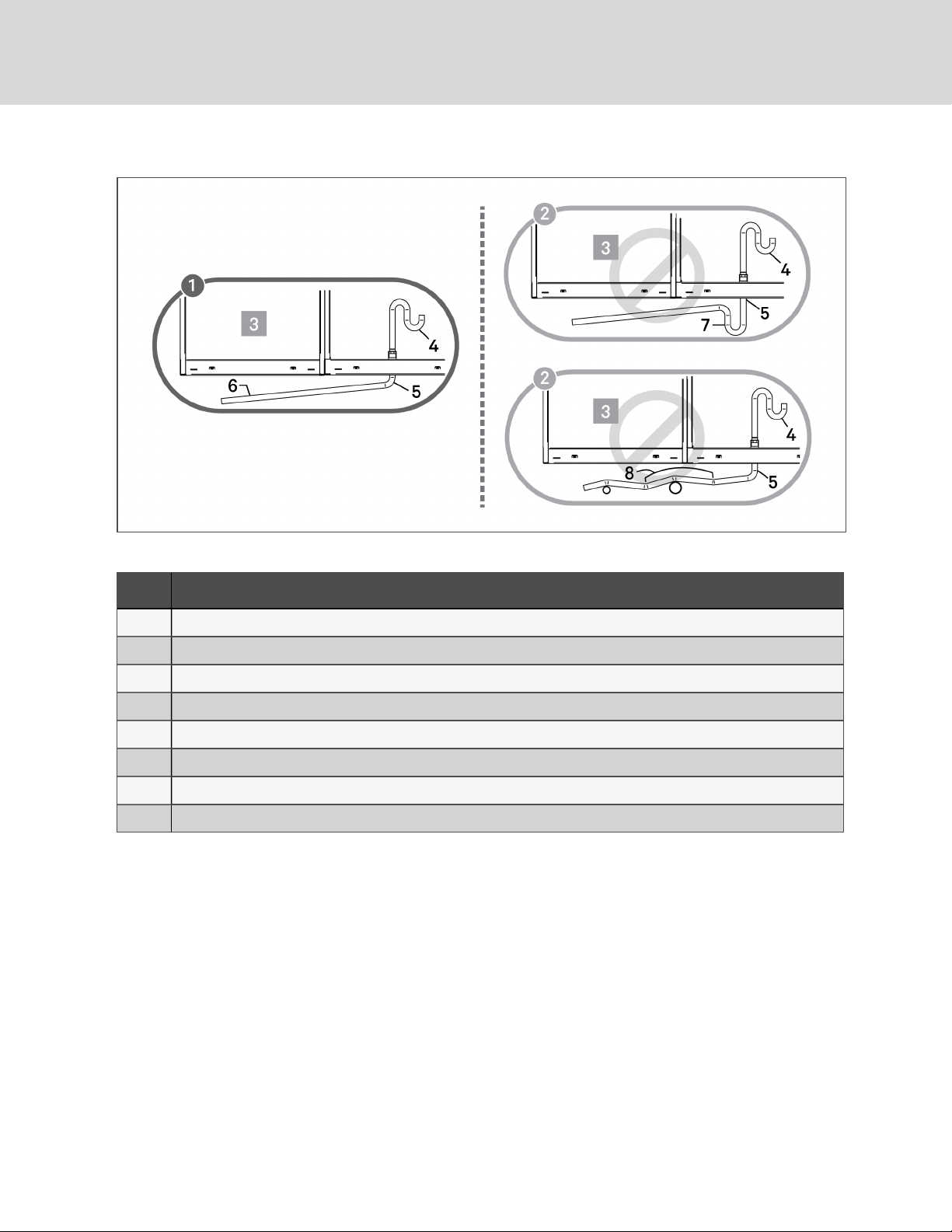
Figure 3.2 Correct and Incorrect condensate-drain line
Table 3.2 Evaporator Drain-line Figure Descriptions
Item Description
1 Correct drain-line installation
2 Incorrect drain-line installation
3 DSEunit
4 Internal drain
5 Externaldrain
6 Continuousdownward slope
7 External trap. Do not trap externally.
8 External traps, although unintentional. Lines must be rigidenough not to bow over top of other objects.
3.3 Operating Conditions
The Liebert® DP060 must supply air to a conditioned space within the operating envelope that ASHRAE
recommends for data centers. Operating the DP060 outside of this envelope can decrease equipment
reliability. Refer to ASHRAE’s publication, “Thermal Guidelines for Data Processing Environments.”
16
Vertiv | Liebert® DSE060™ Installer/User G uide
Page 17
3.3.1 Cooling
The recommended maximum return-air temperature is 105°F (40°C) and maximum dew point is 59°F
(15°C). The recommended minimum return-air temperature setpoint Dry Bulb is 85°F (29°C).
Operating outside this envelope can decrease equipment reliability.
NOTE: If running in supply-air control, the minimum supply-air setpoint is 68°F(20°C), and the
maximum supply air temperature is 80°F (27°C).
NOTE: When running above 77°F (25°C) supply air temperature, the superheat readings on the
refrigeration circuits may be higher than 7.2°F(–14°C). The EEVs will run out of stroke and limit mass
flow, which will result in higher than normal superheat.
3.4 Unit Weights
Table 3.3 DP060 unit weights
Model Weight, lb (kg)
DP060 Perimeter 5,500 (2,495)
3 Pre-installation PreparationandGuidelines
17
Page 18

This page intentionally left blank
18
Vertiv | Liebert® DSE060™ Installer/User G uide
Page 19
4 EQUIPMENT INSPECTION AND HANDLING
SAFETY INFORMATION
WARNING! Risk of improper moving. Can cause equipment damage, injury or death. Use only
lifting equipment that is rated for the unit weight by an OSHA-certified rating organization. The
center of gravity varies depending on the unit size and selected options. The slings must be
equally spaced on either side of the center of gravity indicator.
Unit weights are listed in DP060 unit weights on page17.
CAUTION: Risk of contact with sharp edges, splinters, and exposed fasteners. Can cause
injury. Only properly trained and qualified personnel wearing appropriate, OSHA-approved PPE
should attempt to move, lift, remove packaging from or prepare the unit for installation.
• Carefully inspect all items for visible or concealed damage.
• Report damage immediately to the carrier and file a damage claim with a copy sent to Vertiv or
to your sales representative.
• Always refer to the location of the center-of-gravity indicators when lifting the unit, see Center-
of-Gravity Indicators on the next page.
Equipment Recommended for Handling the Unit:
• Lift beam
• Slings
• Spreader bars
• Shims and blocks
4 Equipment Inspection and Handling
19
Page 20
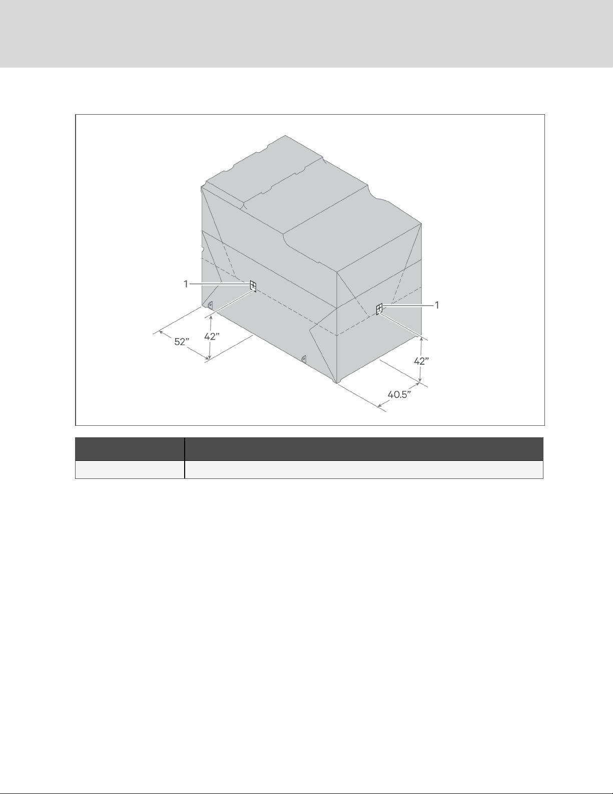
Figure 4.1 Center-of-Gravity Indicators
Item Description
1 Center-of-gravity marker
4.1 Rigging to Lift the Unit
See Lugs to attach rigging to a perimeter-unit configuration on the facing page, for the location of the
lifting lugs on the unit, and use spreader bars and/or shimmed blocks to prevent damage to the unit.
• Unit must remain level when lifted to prevent damage to internal equipment.
• Do not place unit directly on the ground. If the unit must be set down, use shims or blocks for
leveling and to keep unit off the ground.
Before lifting or moving, clear the area of all unnecessary personnel. Clear the area of any debris and
unrelated tools or foreign objects.
20
Vertiv | Liebert® DSE060™ Installer/User G uide
Page 21
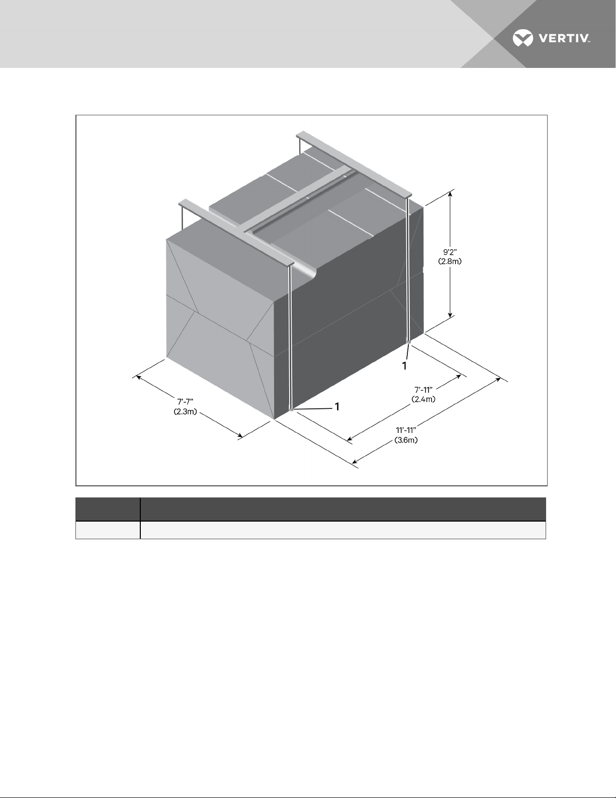
Figure 4.2 Lugs to attach rigging to a perimeter-unit configuration
Item Description
1 Lugs to attach rigging. Typical both sides.
4.2 Using Forklift to Install the Unpackaged Unit
The forklift must be rated for at least 5,500 lb (2495 kg) and the fork length can be no less than 8ft
(2.4m). See Typical Center Line of Fork Pockets on the next page, for the location of fork pockets. The
unit can be lifted from either side.
Place protective material between the fork mast and unit to prevent external damage to the unit.
4 Equipment Inspection and Handling
21
Page 22
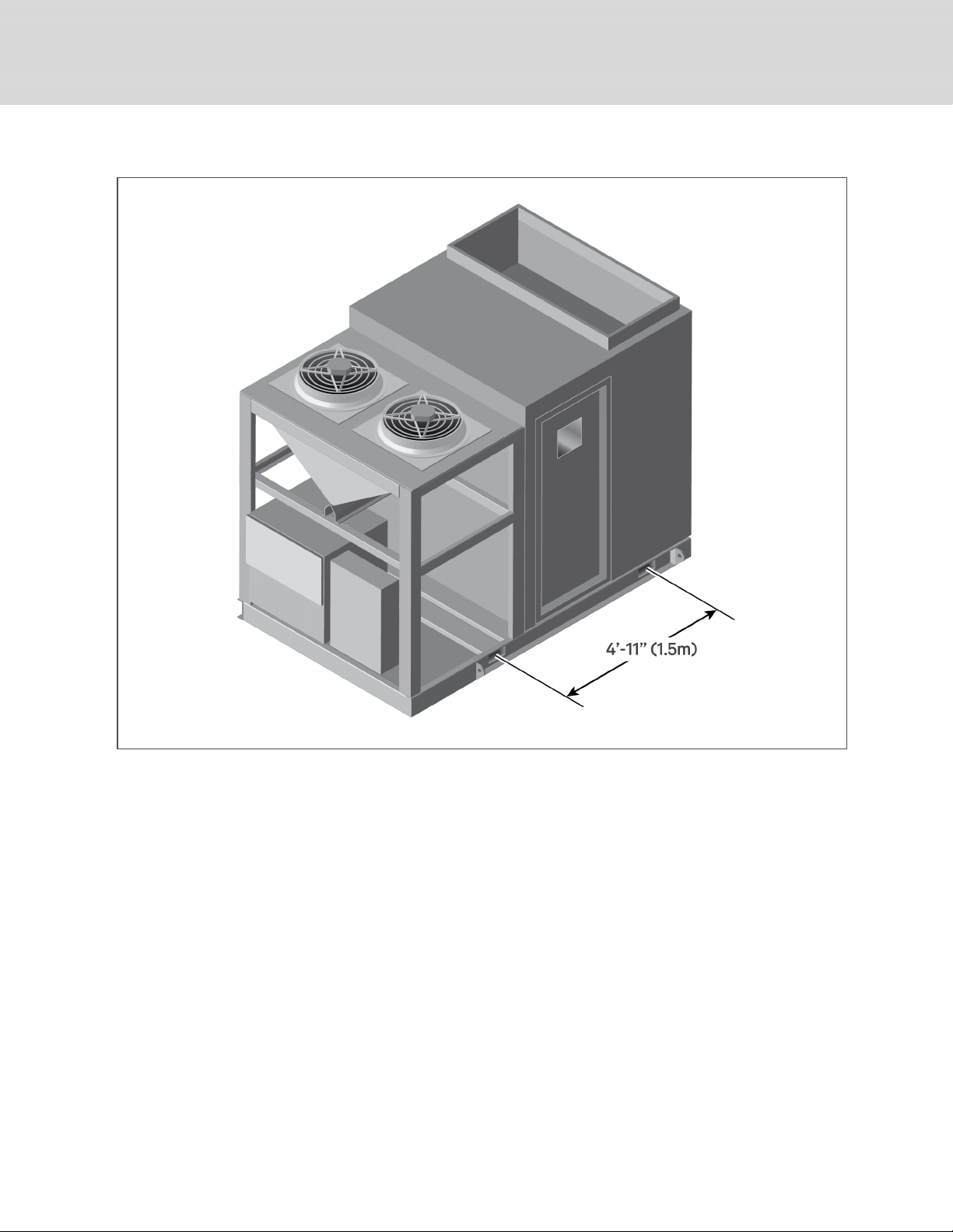
Figure 4.3 Typical Center Line of Fork Pockets
22
Vertiv | Liebert® DSE060™ Installer/User G uide
Page 23
5 ELECTRICAL FIELD CONNECTIONS
Three-phase electrical service is required for all models. Electrical service must conform to national and
local electrical codes. Refer to equipment nameplate regarding wire size and circuit protection
requirements. Refer to the appropriate submittal drawing, listed in Electrical Field-connection Drawings
on page25, for electrical service entrances into unit
A manual electrical disconnect switch should be installed in accordance with local codes and distribution
system. Consult local codes for external disconnect requirements.
WARNING! Arc flash and electric shock hazard. Open all local and remote electric power-supply
disconnect switches, verify with a voltmeter that power is Off and wear appropriate,
OSHA-approved personal protective equipment (PPE) per NFPA 70E before working within the
electric control enclosure. Failure to comply can cause serious injury or death. Customer must
provide earth ground to unit, per NEC, CEC and local codes, as applicable. Before proceeding
with installation, read all instructions, verify that all the parts are included and check the
nameplate to be sure the voltage matches available utility power. The Liebert® controller does
not isolate power from the unit, even in the “Unit Off” mode. Some internal components require
and receive power even during the “Unit Off” mode of the controller. The factory-supplied
disconnect switch is on the exterior of the enclosure. The only way to ensure that there is NO
voltage inside the unit is to install and open a remote disconnect switch. Refer to unit electrical
schematic. Follow all local codes.
WARNING! Risk of electric shock. Can cause equipment damage, injury or death. Open all local
and remote electric power supply disconnect switches and verify with a voltmeter that power is
off before working within any electric connection enclosures. Service and maintenance work
must be performed only by properly trained and qualified personnel and in accordance with
applicable regulations and manufacturers’ specifications. Opening or removing the covers to
any equipment may expose personnel to lethal voltages within the unit even when it is
apparently not operating and the input wiring is disconnected from the electrical source.
WARNING! Risk of improper wire sizing/rating and loose electrical connections. Can cause
overheated wire and electrical connection terminals resulting in smoke, fire, equipment and
building damage, injury or death. Use correctly sized copper wire only and verify that all
electrical connections are tight before turning power On. Check all electrical connections
periodically and tighten as necessary.
WARNING! Risk of wiring damage, short circuits and electric shock. Can cause overheated
wiring, smoke, fire, activation of fire suppression systems and EMS personnel and equipment,
building and equipment damage, injury or death. Insert CSA certified or UL listed bushings into
holes and or knockouts used to route wiring through metal panels to protect the wire
insulation from contact with sheet metal edges.
5 Electrical FieldConnections
23
Page 24

NOTICE
NOTICE
Risk of improper power-supply connection. Can cause equipment damage and loss of warranty
coverage.
Prior to connecting any equipment to a main or alternate power source (for example: back-up
generator systems) for start-up, commissioning, testing, or normal operation, ensure that these
sources are correctly adjusted to the nameplate voltage and frequency of all equipment to be
connected. In general, power-source voltages should be stabilized and regulated to within
±10% of the load nameplate nominal voltage. Also, ensure that no three-phase sources are
single-phased at any time.
Risk of improper electrical connection of three-phase input power. Can cause backward
compressor rotation and unit damage. Service technicians should use a gauge set on the
system during the initial start up to verify that the three-phase power is connected properly.
The EC fans are not a reliable indicator of proper connection. The blowers will rotate the same
direction, regardless of the three-phase power input. Three-phase power must be connected
to the unit line voltage terminals in the proper sequence so that the compressors rotate in the
proper direction. Incoming power must be properly phased to prevent compressors from
running backward. We recommend checking the unit’s phasing with proper instrumentation to
ensure that power connections were made correctly. We also recommend verifying discharge
and suction pressures during start up to ensure that the compressors are running in the
correct direction.
NOTICE
Risk of improper electrical supply connection. Can cause equipment damage. See transformer
label for primary tap connections. Installer will need to change transformer primary taps if
applied unit voltage is other than pre-wired tap voltage.
NOTE: Seal openings around electrical connection to prevent water leakage. Connections must be
water-tight. Failure to do so risks damage to the outdoor unit.
24
Vertiv | Liebert® DSE060™ Installer/User G uide
Page 25
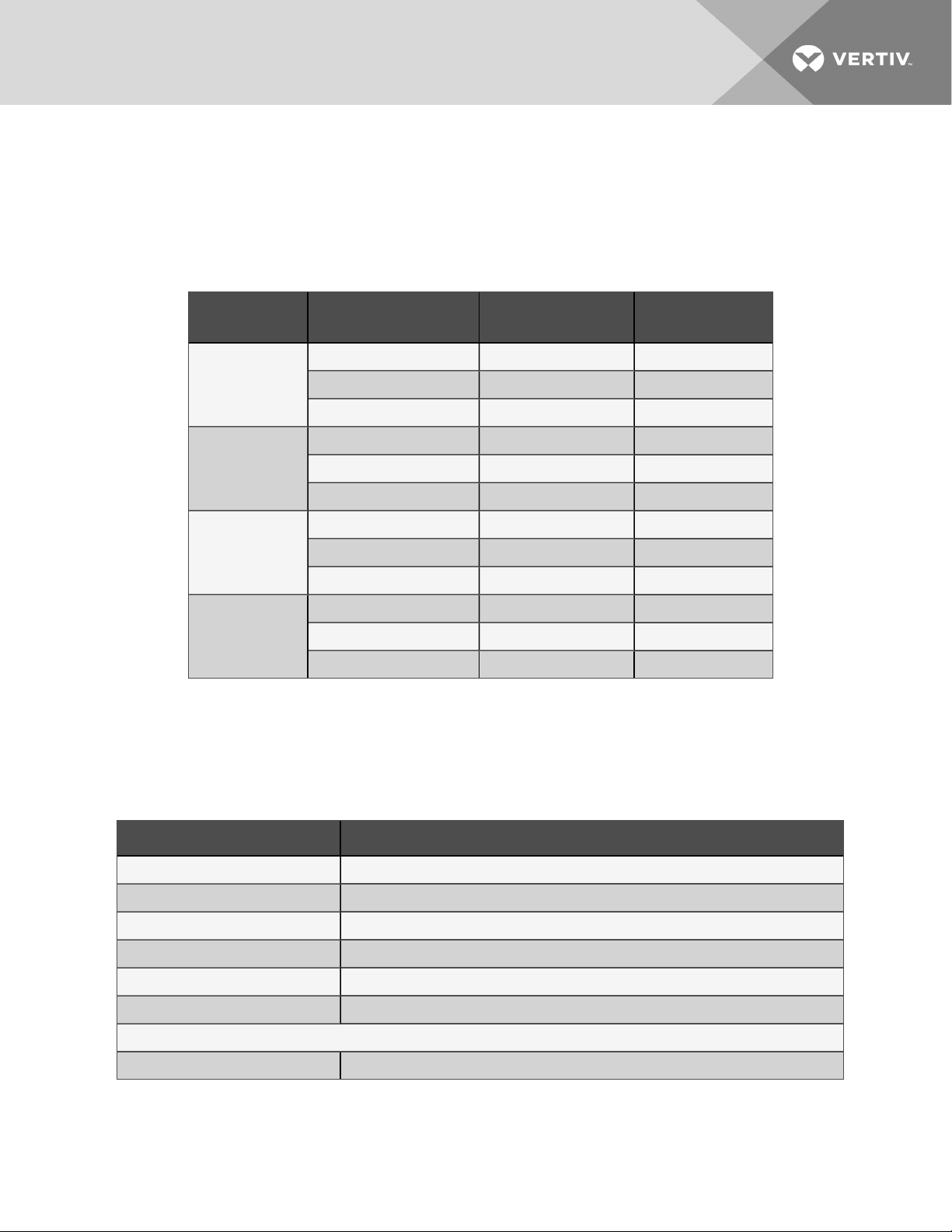
The unit requires two separate power-supply connections:
• A 3-phase; 208-V, 230-V, 460-V. or 575-V; 60-Hz, power supply to the DP060 unit electrical
enclosure.
• A separate 120-V power feed to the unit electrical enclosure (for light switches/convenience
outlet).
Table 5.1 Electrical Data—DP060, 60Hz
Unit V oltage Rating
208V, 3ph, 60Hz
230 V, 3ph, 60Hz
460 V, 3ph, 60 Hz
575 V, 3ph, 60 Hz
standard ambient condenser:
Total system with
FLA 70.1 76.4
WSA 84.4 90.6
OPD 125 125
FLA 66.9 79.4
WSA 79.8 92.3
OPD 125 125
FLA 33.2 39.4
WSA 39.6 45.8
OPD 60 60
FLA 27.5 33.8
WSA 33.0 39.3
OPD 50 60
without 120-V transformer with 120- V transformer
The electrical connections are described in the submittal documents included in the Submittal Drawings
on page69. After all unit wiring is complete, you can use the iCOM control to set operating setpoints. See
the Liebert® iCOM User Guide, SL-31075.
The following table lists the relevant documents by number and title.
Table 5.2 Electrical Field-connection Drawings
Document Number Title
DPN004587 Electrical Connections Enclosure, Dualpower input
DPN004732 Electrical Connections Enclosure, Single power input
DPN004591 Evaporator Electrical Panel component definitions and locations
DPN004350 Liebert® iCOM Unit-mounted Display
DPN000960 Liebert® iCOM Remote temperature and humidity sensor
DPN003144 Liebert® iCOM Service bracket
Unit-to-Unit Networking
DPN004351 Liebert® iCOM Unit-to-unit Network Connections
5 Electrical FieldConnections
25
Page 26

This page intentionally left blank
26
Vertiv | Liebert® DSE060™ Installer/User G uide
Page 27

6 CHECKLIST FOR COMPLETED INSTALLATION
6.1 Moving and Placing Equipment
1. Unpack and check received material.
2. Proper clearance for service access has been maintained around the equipment.
3. Equipment is level and mounting fasteners are tight.
4. Proper condensate-drain system is in place.
6.2 Electrical Installation Checks
1. Supply voltage and phase matches equipment nameplate.
2. Power wiring connections completed to the disconnect switch.
3. Power line circuit breakers or fuses have proper ratings for equipment installed.
4. All internal and external high- and low-voltage wiring connections are tight.
5. Confirm that unit is properly grounded to an earth ground.
6. Control transformer setting matches incoming power.
7. Electrical service conforms to national and local codes.
8. Confirm that power-wiring connections to the utility box are completed.
6.3 Other Installation Checks
1. Ducting complete.
2. Confirm ducting is attached to unit and building structure, and any openings around supplyand return-duct connections are sealed.
3. Filters installed.
4. Check fasteners that secure evaporator-fan motors—some may have become loose during
shipment.
5. Check blowers and compressor for proper rotation.
6. Drain line connected, not obstructed, and pitched per local code.
7. All fans are free of debris.
8. Seal openings around electrical connections and make sure that the seals are water-tight.
9. Installation materials and tools have been removed from equipment (literature, shipping
materials, construction materials, tools, etc.).
10. Check for refrigerant leaks.
11. Make sure heat load is available during initial start-up. Consult factory for assistance.
6 Checklist for CompletedInstallation
27
Page 28

6.4 BMS and Sensor Installation Checks
1. CAT5 cables are installed from each unit and the network switch, and all cables have RJ45
jacks on each end.
2. The network switch/Liebert® vNSA panel (if present) is installed and powered.
3. Confirm the static-pressure-sensor transducer (if present) is installed in the room and wired
back to the DP060 unit
4. Confirm the supply-air sensor is installed in the best location possible to obtain a temperature
reading representative of the supply air in the duct or plenum serviced by the unit and that
the sensor is wired back to the unit control panel.
5. All remote and 2T rack sensors (if present) are installed and wired using CANBUS cables.
28
Vertiv | Liebert® DSE060™ Installer/User G uide
Page 29
7 INITIAL START-UP CHECKS
ANDCOMMISSIONINGPROCEDURE
FORWARRANTYINSPECTION
WARNING! Arc flash and electric shock hazard. Open all local and remote electric power-supply
disconnect switches, verify with a voltmeter that power is Off and wear appropriate,
OSHA-approved personal protective equipment (PPE) per NFPA 70E before working within the
electric control enclosure. Failure to comply can cause serious injury or death. Customer must
provide earth ground to unit, per NEC, CEC and local codes, as applicable. Before proceeding
with installation, read all instructions, verify that all the parts are included and check the
nameplate to be sure the voltage matches available utility power. The Liebert® controller does
not isolate power from the unit, even in the “Unit Off” mode. Some internal components require
and receive power even during the “Unit Off” mode of the controller. The factory-supplied
disconnect switch is on the exterior of the enclosure. The only way to ensure that there is NO
voltage inside the unit is to install and open a remote disconnect switch. Refer to unit electrical
schematic. Follow all local codes.
WARNING! Risk of improper wiring, piping, moving, lifting and handling. Can cause equipment
damage, serious injury or death. Installation and service of this equipment should be done only
by qualified personnel who have been specially-trained in the installation of air-conditioning
equipment and who are wearing appropriate, OSHA-approved PPE.
NOTICE
Risk of improper electrical connection of three-phase input power. Can cause backward
compressor rotation and unit damage. Service technicians should use a gauge set on the
system during the initial start up to verify that the three-phase power is connected properly.
The EC fans are not a reliable indicator of proper connection. The blowers will rotate the same
direction, regardless of the three-phase power input. Three-phase power must be connected
to the unit line voltage terminals in the proper sequence so that the compressors rotate in the
proper direction. Incoming power must be properly phased to prevent compressors from
running backward. We recommend checking the unit’s phasing with proper instrumentation to
ensure that power connections were made correctly. We also recommend verifying discharge
and suction pressures during start up to ensure that the compressors are running in the
correct direction.
• Confirm that all items on Checklist for Completed Installation on page27 have been done.
• Locate “Liebert® DP060 Warranty Inspection Check Sheet” in the unit’s electric panel.
• Complete “Liebert® DP060 Warranty Inspection Check Sheet” during start-up.
• Forward the completed “Liebert® DP060 Warranty Inspection Check Sheet” to your local sales
office. This information must be completed and forwarded to validate warranty.
• Contact your local sales representative or technical support if you have any questions or
problems during unit start-up and commissioning. Visit https://www.vertivco.com/enus/support/ or call 1-800-543-2778 for contacts.
7 Initial Start-up Checks andCommissioningProcedure forWarrantyInspection
29
Page 30

This page intentionally left blank
30
Vertiv | Liebert® DSE060™ Installer/User G uide
Page 31
8 MAINTENANCE
WARNING! Arc flash and electric shock hazard. Open all local and remote electric power-supply
disconnect switches, verify with a voltmeter that power is Off and wear appropriate,
OSHA-approved personal protective equipment (PPE) per NFPA 70E before working within the
electric control enclosure. Failure to comply can cause serious injury or death. Customer must
provide earth ground to unit, per NEC, CEC and local codes, as applicable. Before proceeding
with installation, read all instructions, verify that all the parts are included and check the
nameplate to be sure the voltage matches available utility power. The Liebert® controller does
not isolate power from the unit, even in the “Unit Off” mode. Some internal components require
and receive power even during the “Unit Off” mode of the controller. The factory-supplied
disconnect switch is on the exterior of the enclosure. The only way to ensure that there is NO
voltage inside the unit is to install and open a remote disconnect switch. Refer to unit electrical
schematic. Follow all local codes.
WARNING! Risk of electric shock. Can cause equipment damage, injury or death. Open all local
and remote electric power supply disconnect switches and verify with a voltmeter that power is
off before working within any electric connection enclosures. Service and maintenance work
must be performed only by properly trained and qualified personnel and in accordance with
applicable regulations and manufacturers’ specifications. Opening or removing the covers to
any equipment may expose personnel to lethal voltages within the unit even when it is
apparently not operating and the input wiring is disconnected from the electrical source.
WARNING! Risk of improper wiring, piping, moving, lifting and handling. Can cause equipment
damage, serious injury or death. Installation and service of this equipment should be done only
by qualified personnel who have been specially-trained in the installation of air-conditioning
equipment and who are wearing appropriate, OSHA-approved PPE.
The Liebert® DP060 Packaged Solution is a single component in the facility heat-removal system. Proper
application and maintenance of the entire system is critical to the life and reliability of the thermalmanagement units.
• Good maintenance practices are essential to minimizing operation costs and maximizing
product life.
• Read and follow monthly and semi-annual maintenance schedules included in this manual.
These MINIMUM maintenance intervals may need to be more frequent based on site-specific
conditions.
• See the Liebert®iCOM™ user manual, SL-31075, available at www.vertivco.com, for instructions
on using the controller to predict some service maintenance intervals.
• We recommend the use of trained and authorized service personnel, extended service
contracts and factory-specified replacement parts. Contact your Vertiv sales representative.
8 Maintenance
31
Page 32
8.1 Service/Maintenance Access to the Evaporator Compartment
The evaporator section includes access doors that swing inward on both sides to allow access for
maintenance on components within the evaporator compartment.
For the location of components that require maintenance, see the appropriate pages of the submittal
drawing DPN004597 included in the Submittal Drawings on page69. Plan access through at least one
door to allow for removal of evaportor coil. See notes on DPN004602 for recommended clearance.
NOTICE
Risk of equipment damage. The evaporator access panel cannot be opened while the exterior
man door is closed.
CAUTION: Risk of low-hanging panels. Can cause injury or equipment damage. Wear
appropriate, OSHA-approved PPE when entering and working within the enclosure.
8.2 Filters
NOTICE
Risk of improper filter installation. Can cause filter collapse and airflow reduction.
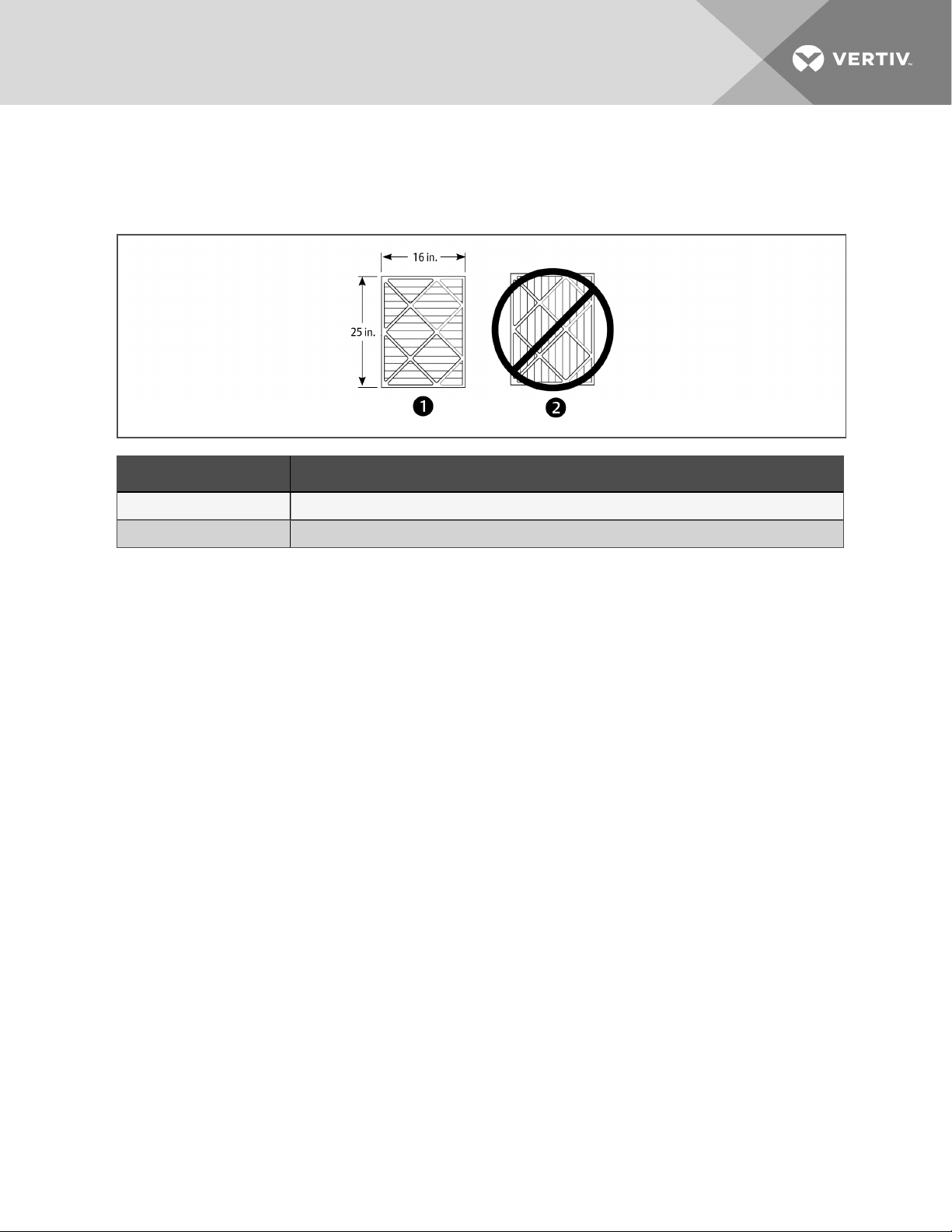
Pleat direction is non-standard. Use only short-pleat filters (see Proper filter pleat direction). Long-pleat
filters are subject to collapse at high airflows.
To maximize the performance and reliability of the equipment, use only Vertiv filters. Contact your Vertiv
representative to order replacement filters.
Verify that filters are installed and positioned so the air-flow direction marked on the filter is the same
direction as unit air flow.
Table 8.1 Filter Quantities
Number of Filters
Unit S ize Filter Size, WidthxLength, in. (mm)
25 x 16 (635 x 406) 1
DP060
25 x 20 (635 x 508) 2
4in. (102mm)Filter Option,
MERV8, MERV11 or MERV13
8.2.1 Filter-replacement
1. Disconnect power from the unit.
2. Open the front access panel, locate the filter above the electric panel, and slide the filter out
the front of the unit.
3. Replace with new filter—install the filter in the proper direction of the airflow.
4. Test the operation of the filter clog switch.
The unit panels must be in place and closed to find this point.
32
Vertiv | Liebert® DSE060™ Installer/User G uide
Page 33
5. Start the blower and turn the switch counterclockwise until the alarm is energized.
6. Turn the adjusting knob one turn clockwise or to the desired filter change point.
Figure 8.1 Proper filter pleat direction
Item Description
1 Short pleat construc tion
2 Long pleat construction
8 Maintenance
33
Page 34
8.3 Evaporator Blower Drive System—EC Fans
WARNING! Risk of electric shock. Can cause serious injury or death. Open all local and remote
electric power-supply disconnect switches and verify with a voltmeter that power is off before
opening the fan motor electric-connection enclosure. Use only fully-trained and qualified HVAC
technicians to replace or perform maintenance on the fans.
CAUTION: Risk of contact with hot surfaces. Can cause burn injury. The EC fans and
electronics housing are extremely hot during operation. Allow sufficient time for them to cool
to a touch-safe temperature before handling. Use extreme caution and wear appropriate,
OSHA-approved PPE when replacing or performing maintenance on the EC fans.
CAUTION: Risk of improper moving, lifting and handling. Can cause equipment damage or
injury. Only properly trained and qualified personnel should work on this equipment. Fan
modules weigh in excess of weigh in excess of 125lb (57kg). Use proper lifting techniques and
wear appropriate, OSHA-approved PPE to avoid injury and dropping the fan module during
removal. Equipment used in handling/lifting, and/or installing the fan assembly must meet
OSHA requirements. Use handling/lifting equipment rated for the weight of the fan assembly.
Use ladders rated for the weight of the fan assembly and technicians if used during installation.
Refer to handling/lifting, and/or installation equipment operating manual for manufacturer's
safety requirements and operating procedures.
NOTICE
Risk of improper power-supply connection. Can cause equipment damage and loss of warranty
coverage.
Prior to connecting any equipment to a main or alternate power source (for example: back-up
generator systems) for start-up, commissioning, testing, or normal operation, ensure that these
sources are correctly adjusted to the nameplate voltage and frequency of all equipment to be
connected. In general, power-source voltages should be stabilized and regulated to within
±10% of the load nameplate nominal voltage. Also, ensure that no three-phase sources are
single-phased at any time.
NOTICE
Risk of improper installation. Can cause equipment damage.
Only a properly trained and qualified technician should install or open this motor.
Use 60/75°C Class 1 copper wire only.
8.3.1 Protective Features
Monitoring functions protect the motor against overtemperature of electronics, overtemperature of motor
and incorrect rotor position detection. With any of these failures, an alarm will display through the
Liebert® iCOM controller and the motor stops electronically. There is no automatic restart. The power
must be switched off for a minimum of 20 seconds once the motor is at a standstill.
34
Vertiv | Liebert® DSE060™ Installer/User G uide
Page 35
The motor also provides locked rotor protection, undervoltage/phase failure detection and motor current
limitation. These conditions will display an alarm through the Liebert® iCOM.
8.3.2 Fan Impellers and Bearings Maintenance
Fan impellers should be periodically inspected and any debris removed. Check to ensure that the
impellers can rotate freely and that the fan guards are still properly mounted for sufficient protection
against accidentally contacting the impeller. Bearings used on the units are maintenance-free. Consult
the factory for more information.
8.3.3 Fan Assembly Troubleshooting
Any safety hazards stemming from the device must be re-evaluated once it is installed in the end device.
Do not make any modifications, additions or conversions to the fan assembly without the approval of
Vertiv.
WARNING! Risk of electric shock. Can cause serious injury or death. Open all local and remote
electric power-supply disconnect switches and verify with a voltmeter that power is off before
opening the fan motor electric-connection enclosure. Use only fully-trained and qualified HVAC
technicians to replace or perform maintenance on the fans.
WARNING! Risk of contact with high-speed rotating fan blades. Can cause serious injury or
death. Open all local and remote electric power-supply disconnect switches, verify with a
voltmeter that power is off, and verify that all fan blades have stopped rotating before working
in the unit cabinet or on the fan assembly. If control voltage is applied, the fan motor can restart
without warning after a power failure.
8 Maintenance
35
Page 36
NOTICE
CAUTION: Risk of exposure to harmful noise levels. Can cause hearing injury or loss.
Depending on the installation and operating conditions, a sound pressure level greater than
70dB(A) may arise. Take appropriate technical safety measures. Operating personnel must
wear appropriate, OSHA-approved PPE and observe all appropriate hearing-protection safety
requirements.
CAUTION: Risk of contact with hot surfaces. Can cause injury. The compressor, refrigerant
discharge lines, fan motor, and some electrical components are extremely hot during unit
operation. Allow sufficient time for them to cool to a touch-safe temperature before working
within the unit cabinet. Use extreme caution and wear appropriate, OSHA-approved PPE when
working on or near hot components.
Risk of improper power-supply connection. Can cause equipment damage and loss of warranty
coverage.
Prior to connecting any equipment to a main or alternate power source (for example: back-up
generator systems) for start-up, commissioning, testing, or normal operation, ensure that these
sources are correctly adjusted to the nameplate voltage and frequency of all equipment to be
connected. In general, power-source voltages should be stabilized and regulated to within
±10% of the load nameplate nominal voltage. Also, ensure that no three-phase sources are
single-phased at any time.
NOTE: Do not assume that the fan blades will not start to spin. If the motor is in a fault condition, it will
safely shut down. Once the fault condition is cleared, there are certain conditions in which the motor
will automatically resume operation.
EC-fan Fault Conditions
Table 8.2 EC-fan Fault Conditions
Fault Condition Reset Trigger Description
Phase Failure Automatic
Locked/Blocked
Rotor
Hall Effect
Sensor Error
Motor Over
Temperature
Electronics Over
Temperature
Line
Under-Voltage
Automatic
Manual
(Mains/Software)
Manual
(Mains/Software)
Manual
(Mains/Software)
Automatic
One phase is missing. In this c ase the motor willcome to a stop andthen automatically restart
when allphases are present.
The rotor is blocked. Once the locking mechanism has been removed, the motor will
automaticallyrestart.
The Hall Effect Sensor is used to monitor fan speed. If there is a hall sensor c ommunication
failure with the electronics, the motor willstop. In this case there has to be a manual restart
(either with the mains power or software).
The motor willstop in the event there is amotor over temperature condition. In this case
there has to be a manual restart (either with the mains power or software).
The motor willstop in the event there is anelectronics over temperature c ondition. In this
case there has to be a manualrestart (either with the mains power or software).
Once the line voltage returns within permitted operating range, the fan willautomatically
restart.
36
Vertiv | Liebert® DSE060™ Installer/User G uide
Page 37
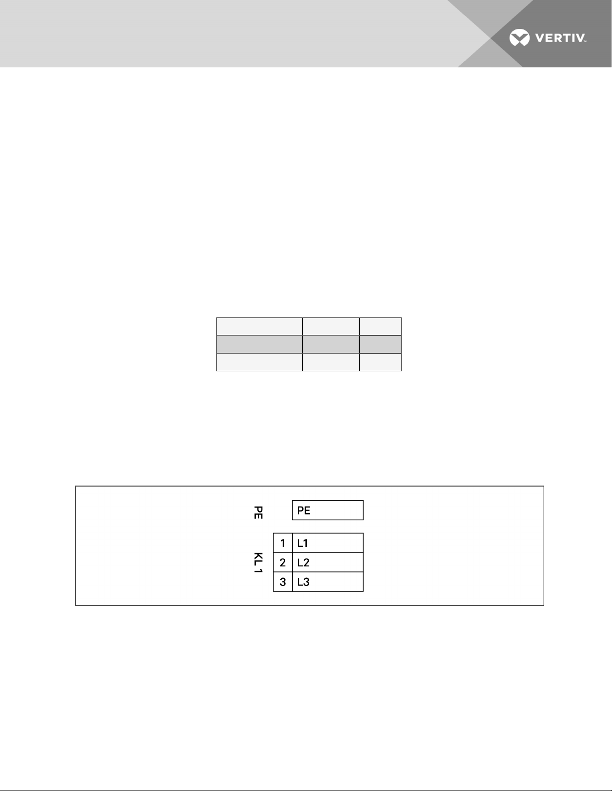
EC-fan High-voltage Tests
1. Check Fuses. If fuses are okay, perform the following:
• Check all connections.
• Make sure connections are on the wire strand and not on the wire insulation.
• Cycle Power. Disconnect mains voltage to power down the motor and then re-apply
power.
• Check mains voltage at each phase (phase to ground) at the KL1 connector.
Confirm phase failure not present.
• Check that the voltage is within the acceptable voltage range at the KL1
connector. Confirm line under-voltage is not present.
2. Check Fuses. If fuses are blown, perform the following:
• Check resistances across the phases at the KL1 connector and note them in the
following table..
NOTE: Power wires must be removed from the motor for resistance test.
L1 - L2 Ohm
L2 - L3 Ohm
L1 - L3 Ohm
• Resistances should be similar for all 3 readings.
• Resistance readings should be greater than 2Ohm.
• Check all connections. Make sure connections are on the wire strand and not on
the wire insulation.
• Replace Fuses.
• Check mains voltage at each phase (phase to ground) at the KL1 connector.
Confirms phase failure not present.
8 Maintenance
• Check that the voltage is within the acceptable voltage range at the KL1
connector. Confirmsline under-voltage is not present.
37
Page 38
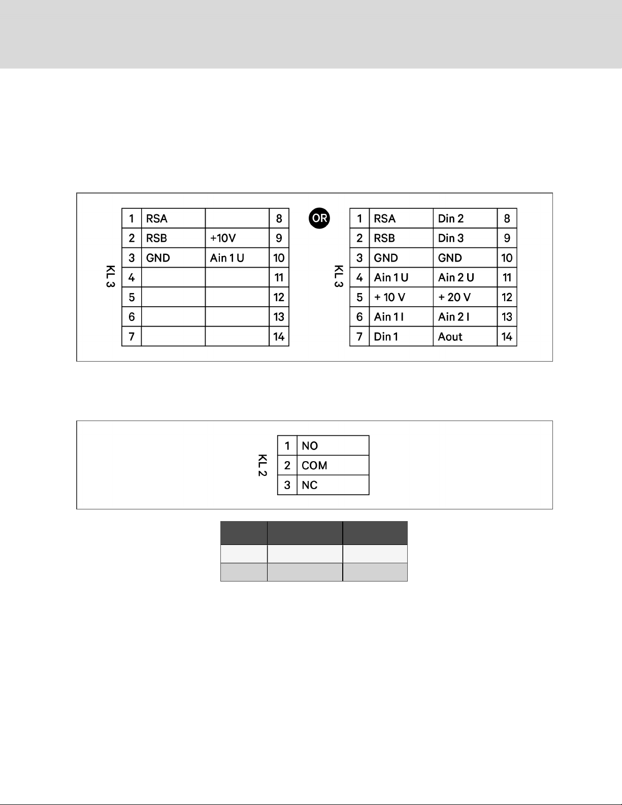
EC-fan Low-voltage Tests
• Check control input at the KL3 connector (Ain1U to GND). Confirm that there is a
control voltage present at the KL3 connector.
NOTE: Use the GND in the KL3 connector. Do not connect the control ground to the PE in KL1!
• Check +10 V output on KL3 connector (between +10 V and GND).
EC-fan Alarm Contact Tests
Check the alarm contact at KL2 to determine if there are any fault conditions present.
Condition No Fault Condition Fault Condition
NO - COM Open Closed
NC - COM Closed Open
NOTE: The table refers to conditions while the motor is actively energized. When the motor is deenergized, it will be in a fault condition.
• Check EC Control to determine the fault condition.
38
Vertiv | Liebert® DSE060™ Installer/User G uide
Page 39
8.3.4 Removing Evaporator EC Fans
The EC fan in Liebert® DP060 units can be removed for easier maintenance or for replacement.
WARNING! Risk of electric shock and contact with high speed rotating fan blades! Can cause
injury or death! Open all local and remote electric power supply disconnect switches, verify with
a voltmeter that power is off, and verify that fan blades have stopped rotating before working
within the unit cabinet.
WARNING! Risk of extremely heavy fan modules dropping downward suddenly. Can cause
injury or death. Evaporator fan modules weigh in excess of 125-lb (56.7-kg) each. Support fan
modules before removing mounting hardware. Use caution to keep body parts out of fan
module pathway of movement during removal. Only properly trained and qualified personnel
should work on this equipment.
Read these instructions and unit labeling before removing fan modules.
Hardware and Tools Required
• 1/2” hex socket and wrench
• Cable tie cutter
• Field-supplied fan removal device capable of supporting fan assembly weight
To remove an EC fan module:
1. Remove middle and bottom panels from the front of the evaporator unit located inside the
side-access door.
8 Maintenance
39
Page 40
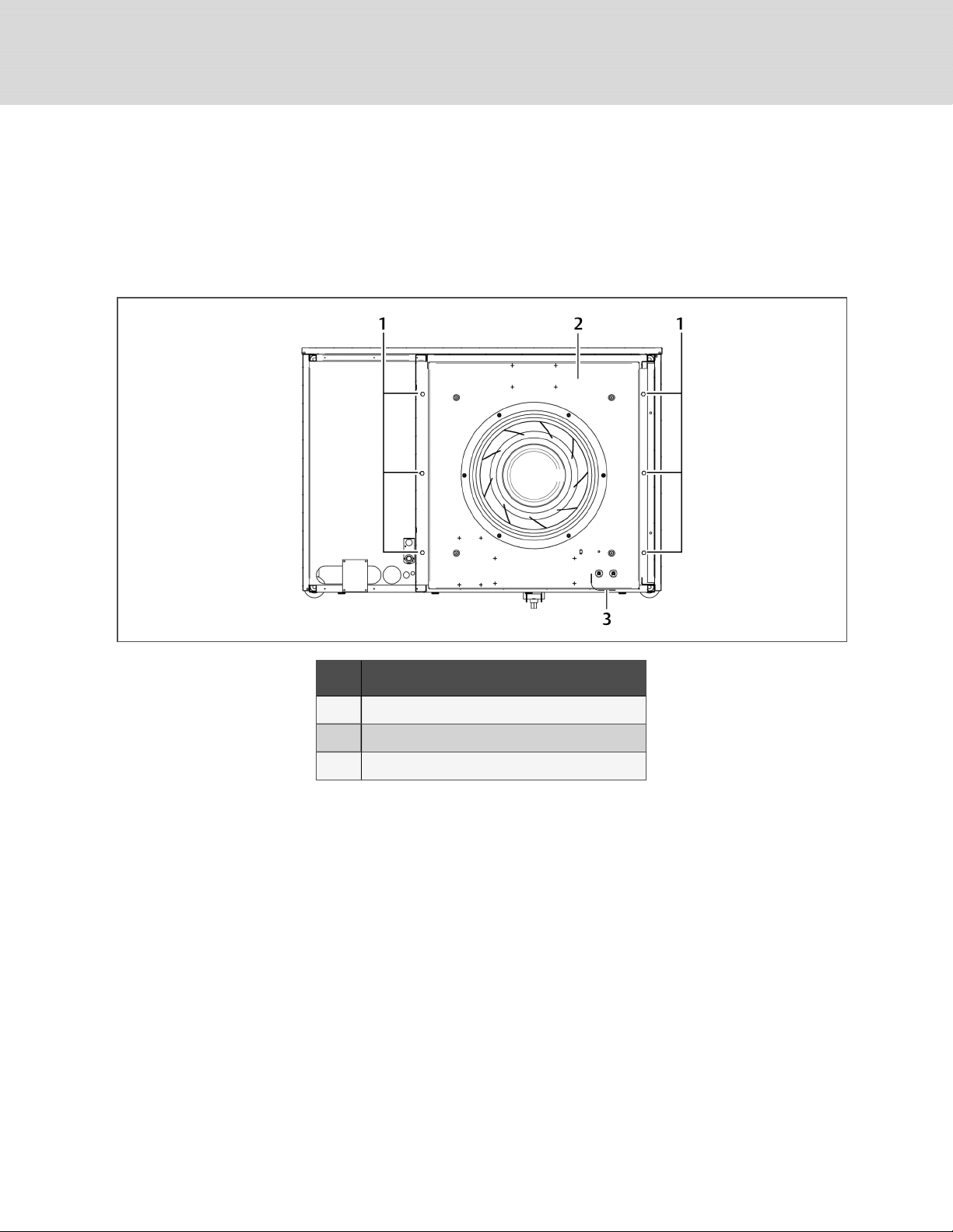
2. Insert a field-supplied fan-removal device securely on the front and rear frame channels under
the fan module as shown in Figure 8.3 on the facing page.
• A suitable fan-removal device is two lengths of rigid material that is 4 inches (100mm)
wide and strong enough to support the weight of the fan module.
3. Remove hardware, Figure 8.2 below, and save it forre-installation.
Figure 8.2 Hardware removal
Item Description
1 1/2-in. (13-mm) Hex-head bolts (typical both sides)
2 Fan deck
3 Wiring loop
40
Vertiv | Liebert® DSE060™ Installer/User G uide
Page 41
4. Disconnect high-voltage and low-voltage fan-motor wiring from the fan-motor electric
component inside the electric panel. Cut cable ties as needed.
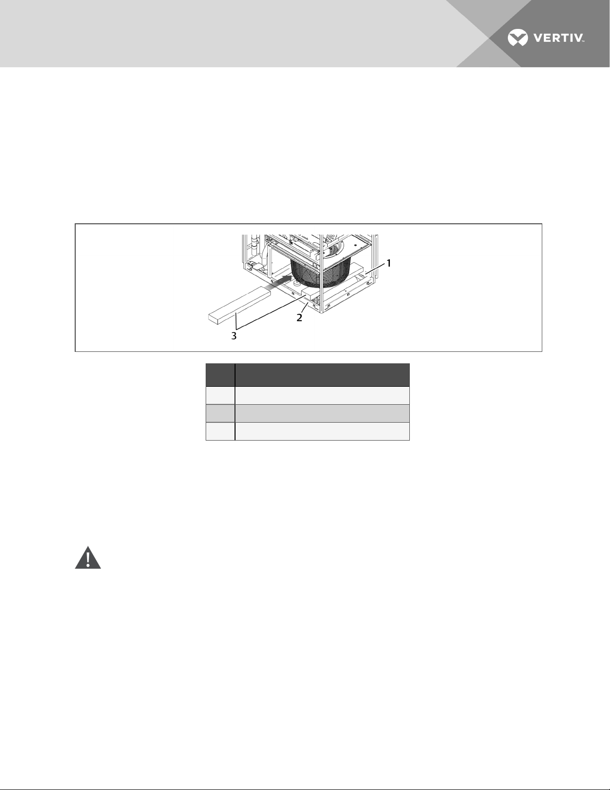
5. Using the removal device shown inserted in Figure 8.3 below, slide the fan module out
through the front of the evaporator unit.
6. To reinstall the fan module, reverse these steps. Remove the field-supplied fan-removal device
before resuming operation.
NOTE: Refer to the unit's electrical schematic for specific wire-attachment points.
Figure 8.3 Slide EC fan out of the unit
Item Description
1 Rear frame channel (right-sidepanelnot shown)
2 Front channel
3 Fan-removaldevices
8.4 Electronic Expansion Valve (EEV) Maintenance
The EEV controls superheat through the Liebert® iCOM™ controls by actively measuring suction
pressure via a transducer attached to the suction-line rotalock and suction temperature via a thermister
strapped to the suction line. The EEV actively adjusts the orifice size and resulting mass flow of refrigerant
to maintain the superheat setpoint (set in Liebert® iCOM). The EEV is used in place of the standard
thermal expansion valve (TXV).
WARNING! Risk of electric shock. Can cause serious injury or death. The Liebert® iCOM
microprocessor does not isolate power from the unit, even in the "Unit Off" mode. Some internal
components require and receive power even during the "unit off" mode of the Liebert® iCOM
control. Open all local and remote electric power disconnect switches and verify with a
voltmeter that power is Off before working on any component of the system.
NOTE: Intermittent loss of subcooling may result in EEV/superheat instability.
8 Maintenance
41
Page 42
8.5 Compressor Maintenance
8.5.1 Compressor Oil
NOTICE
Risk of improper compressor lubrication. Can cause compressor and refrigerant system
damage.
Failure to use oil types, viscosities and quantities recommended by the compressor
manufacturer may reduce compressor life and void the compressor warranty.
• Do not mix polyolester (POE) and mineral-based oils.
• Do not mix oils of different viscosities.
• Consult Vertiv technical support or the compressor manufacturer if questions arise.
8.5.2 Rotalock Valve
WARNING! Risk of explosive discharge of high-pressure refrigerant. Can cause serious injury.
Neutral and service ports on the rotalock valve do not have a valve core. Front-seat the service
valves and relieve pressure from the compressor before loosening a part or a component
attached to the service valve. Follow local codes to properly reclaim refrigerant.
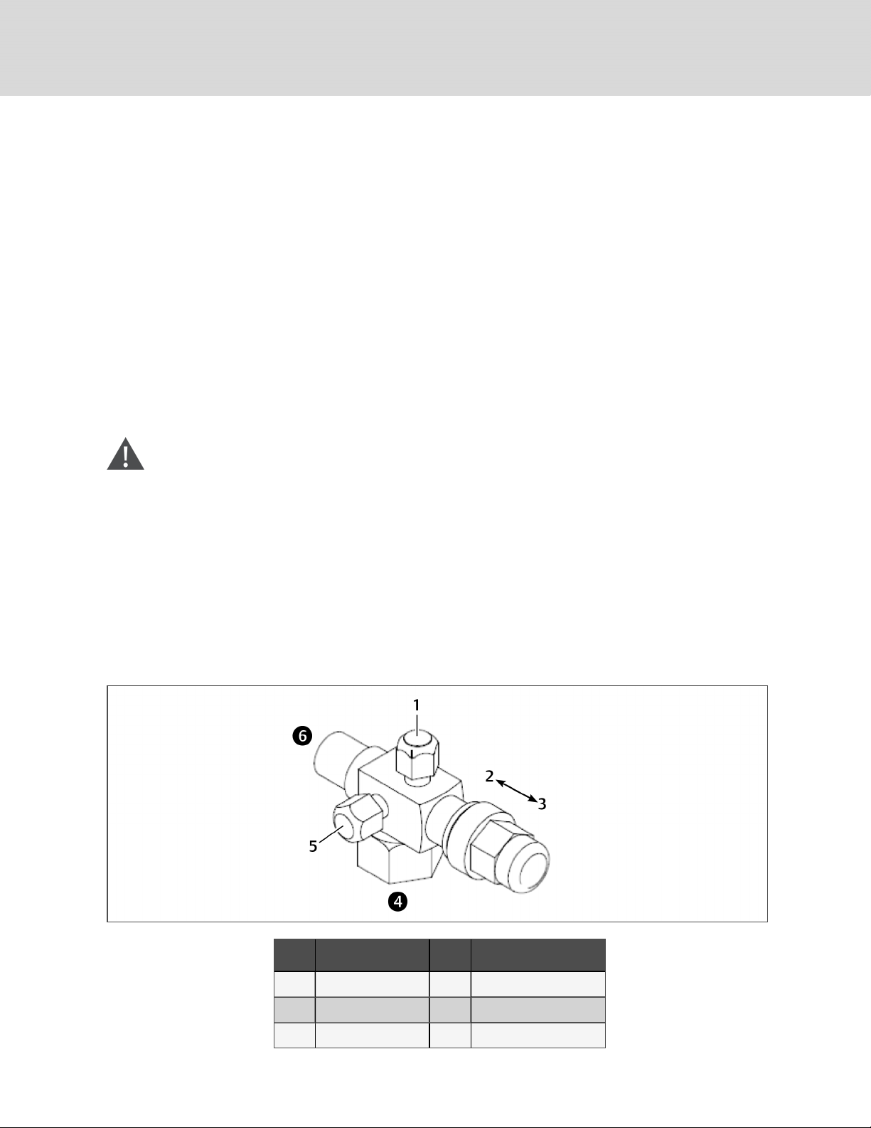
• The Neutral port remains open to the compressor side in all positions of the valve stem, Figure
8.4 below. A high-pressure cut-out switch or low-pressure switch/transducer will be
connected to this port.
• The Service port is closed to the system when valve stem is back-seated, Figure 8.4 below. It is
open to the system as soon as the valve is adjusted away from the back-seated position.
Figure 8.4 Rotalock valve
Item Description Item Description
1 Service port (gauge) 4 Compressor side of valve
2 Front seat 5 Neutral port
3 Back seat 6 System side of valve
42
Vertiv | Liebert® DSE060™ Installer/User G uide
Page 43
8.5.3 Replacement Compressors
Replacement compressors are available through your Vertiv sales office. If the unit is under warranty, the
replacement compressor must be obtained from and the original compressor returned to your local Vertiv
sales office. Compressors are shipped in reusable packaging, and the original compressor should be
returned in the same packaging.
8.5.4 Compressor Motor Burnout
If a burnout has occurred, a full system clean-out is required. If not cleaned, compressor and system
problems will continue.
Consult the factory for compressor maintenance. Do not attempt to remove the compressor without first
contacting Vertiv support at 1-800-543-2778.
8.5.5 Unloading Solenoid(s) on a Digital-scroll Compressor
When replacing a digital-scroll compressor, the digital solenoid valve and coil must be replaced. The
compressor and valve kit are shipped separately. The valve kit must be field-brazed to the top of the
compressor in proper orientation and supported with the original factory bracket.
8.5.6 Replacing the Compressor
WARNING! Risk of electric shock. Can cause serious injury or death. The Liebert® iCOM
microprocessor does not isolate power from the unit, even in the "Unit Off" mode. Some internal
components require and receive power even during the "unit off" mode of the Liebert® iCOM
control. Open all local and remote electric power disconnect switches and verify with a
voltmeter that power is Off before working on any component of the system.
8 Maintenance
WARNING! Risk of over-pressurization of the refrigeration system. Can cause explosive
discharge of high-pressure refrigerant, loss of refrigerant, environmental pollution, equipment
damage, injury, or death. This unit contains fluids and gases under high pressure. Use extreme
caution when charging the refrigerant system. Do not pressurize the system higher than the
design pressure marked on the unit's nameplate.
NOTE: Release of refrigerant to the atmosphere is harmful to the environment. Refrigerant must be
recycled or discarded in accordance with federal, state, and local regulations.
1. Attach suction and discharge gauges to access fittings.
2. Recover refrigerant using an approved recovery procedure and equipment. Use a filter drier
when charging the system with recovered refrigerant.
3. Remove marked pressure transducer and discharge pressure switch. Disconnect all electrical
connections.
4. Remove failed compressor.
5. If required, follow compressor manufacturer’s suggested clean-out procedures.
43
Page 44

6. Install replacement compressor and make all connections. Replace unloading solenoid.
7. Evacuate, charge and operate per the appropriate procedure per local codes:
NOTICE
Risk of improper component re-installation. Can cause equipment damage.
Identify and mark location of suction pressure transducer and discharge pressure switch.
These devices look similar and they must be reinstalled in their original location.
8.6 Evaporator Coil
The DP060 is a single-circuit A-frame coil.
8.7 General Condenser Maintenance
Periodic attention is necessary for continued satisfactory operation of your unit. Restricted air flow
through the condenser coil, reduced airflow from non-functioning fans and low refrigerant system charge
levels will reduce the operating efficiency of the unit and can result in high condensing temperatures and
loss of cooling. In winter, do not permit snow to accumulate around the sides or underneath the condenser
coil.
Monthly and semi-annual inspections and maintenance are recommended for proper system operation.
Use copies of Preventive Maintenance Checklist on page61 for each of these inspections.
8.8 Condenser Cleaning
Keeping the outdoor condenser coils clean is an important factor in maintaining peak efficiency, reliability,
and long life of the equipment. The unit will operate more efficiently with frequent cleanings. If you delay
cleaning until heavy build-up occurs, head-pressure problems with the evaporator units can develop.
8.8.1 When to Clean the Condenser Coil
Normal conditions typically dictate cleaning twice a year, in spring and fall. On-site or area conditions
such as cottonwood trees, construction, etc., can increase cleaning frequency. On your standard monthly
preventive maintenance schedule, we recommend a visual inspection of the coil to monitor conditions.
44
Vertiv | Liebert® DSE060™ Installer/User G uide
Page 45

8.8.2 What to Use to Clean the Condenser Coil
NOTICE
Risk of improper cleaning agent selection, including non-base paint solvents. Can cause
building and equipment damage and loss of refrigerant charge.
Using acid-based or sodium hydroxide-based cleaners can damage the condenser coil and
cause a loss of charge. This could cause equipment damage as well as damage to the
surrounding structure.
Start with removing dirt, leaves, fibers, etc. with a soft brush or vacuum cleaner fitted with a soft-brush
attachment. Do not use a wire brush or scrape the coil with a metal vacuum hose. The best overall
condenser coil cleaner is plain water. If the coil is maintained and cleaned at regular intervals, water is
sufficient to remove dirt and debris from the fins. Water pressure from a garden hose and sprayer usually
works well. If a pressure washer is used, make sure that the equipment is set to a lower pressure setting
and that the nozzle is set to the fan spray, not stream. Otherwise, damage to the fins could result. If a
cleaner is required, we recommend using a neutral cleaner, neither acidic nor base. Acid-type cleaners
can damage the coil fins and surrounding areas. Many sites do not allow the use of acidic cleaners for
environmental reasons.
8.8.3 Cleaning the Condenser Coil
The condenser coil is accessible through the cleaning window, which allows you to clean the coil without
removing the fans from the unit.
To clean the coil:
1. Disconnect the power supply before working on the unit.
2. Open the cleaning window(s) on the side of the condenser by loosening the mounting screws.
3. Insert a spray nozzle on the end of a suitable extension and apply the water/cleaning solution,
working back and forth across the coil face.
The solution pushes dirt and debris out the bottom of the coil.
• If you are using a cleaner along with the spraying process, follow recommended
manufacturer instructions and be sure to rinse the coil thoroughly. Any residue left on
the coil can act as a magnet to dirt.
4. Reinstall the cleaning window(s) and reconnect the power supply to the condenser.
5. Coils will possibly retain water after cleaning and rinsing, so manually reverse the fans briefly
using condenser controls to speed drying of the coils and prevent a possible high-headpressure condition when the condenser is put back into service.
NOTE: Spraying the coil from the outside repeatedly can push a majority of the dirt to the inner section
of the fins and continue to restrict air flow. Keep in mind you may not have the luxury of shutting the
unit(s) down for an extended time. A scheduled shutdown with the operator may be in order.
8 Maintenance
45
Page 46
8.8.4 Cleaning the Condenser Fan
• Clean the EC fan with water only when temperatures are greater than 50°F (10°C)
• Make sure that no water gets into the inside of the motor.
• Do not hold the jet spray directly on the motor openings and seals.
• During cleaning work using a jet spray, no guarantee is assumed regarding corrosion
formation/paint adhesion for unpainted/painted fans.
8.9 Replacing the Condenser Fan
WARNING! Arc flash and electric shock hazard. Open all local and remote electric power-supply
disconnect switches, verify with a voltmeter that power is Off and wear appropriate,
OSHA-approved personal protective equipment (PPE) per NFPA 70E before working within the
electric control enclosure. Failure to comply can cause serious injury or death. Customer must
provide earth ground to unit, per NEC, CEC and local codes, as applicable. Before proceeding
with installation, read all instructions, verify that all the parts are included and check the
nameplate to be sure the voltage matches available utility power. The Liebert® controller does
not isolate power from the unit, even in the “Unit Off” mode. Some internal components require
and receive power even during the “Unit Off” mode of the controller. The factory-supplied
disconnect switch is on the exterior of the enclosure. The only way to ensure that there is NO
voltage inside the unit is to install and open a remote disconnect switch. Refer to unit electrical
schematic. Follow all local codes.
WARNING! Risk of electric shock. Can cause serious injury or death. Open all local and remote
electric power supply disconnect switches and verify with a voltmeter that power is off before
working within the component electric-connection enclosures. Fan-motor controls can
maintain an electric charge for 10 minutes after power is disconnected. Wait 10 minutes after
power is verified as off before working within the fan electric control/connection enclosures.
WARNING! Risk of contact with high-speed, rotating fan impeller blades. Can cause injury or
death. Open all local and remote electric power-supply disconnect switches, verify with a
voltmeter that power is off, and verify that all fan impellers have stopped rotating before
working in the unit cabinet.
CAUTION: Risk of contact with hot surfaces. Can cause burn injury. The EC fans and
electronics housing are extremely hot during operation. Allow sufficient time for them to cool
to a touch-safe temperature before handling. Use extreme caution and wear appropriate,
OSHA-approved PPE when replacing or performing maintenance on the EC fans.
46
Vertiv | Liebert® DSE060™ Installer/User G uide
Page 47

CAUTION: Risk of improper moving, lifting and handling. Can cause equipment damage or
injury. Only properly trained and qualified personnel should work on this equipment. Fan
modules weigh in excess of weigh in excess of 250lb (113.4kg). Use proper lifting techniques
and wear appropriate, OSHA-approved PPE to avoid injury and dropping the fan module during
removal. Equipment used in handling/lifting, and/or installing the fan assembly must meet
OSHA requirements. Use handling/lifting equipment rated for the weight of the fan assembly.
Use ladders rated for the weight of the fan assembly and technicians if used during installation.
Refer to handling/lifting, and/or installation equipment operating manual for manufacturer's
safety requirements and operating procedures.
NOTE: If at any time a parameter is entered and the condenser display does not show 888 or if the
display shows Err, re-enter the parameter. If the display still shows Err after ENT is pressed, power
cycle the control board by unplugging P24, waiting 15 seconds and plugging P24 back in. Contact the
factory if the parameter still displays Err after ENT is pressed.
To replace the fan:
1. Turn Off power to the unit using the disconnect.
2. Use a voltmeter verify that voltage is no longer present at the unit. Wait a minimum of
10minutes to allow the EC fan capacitors to discharge before proceeding.
3. Remove the fan cover, disconnect electrical connections internal to the EC fan and remove the
cable glands from the EC fan to be replaced (see Figure 8.5 on the next page, and Figure 8.6
on page49.
8 Maintenance
47
Page 48
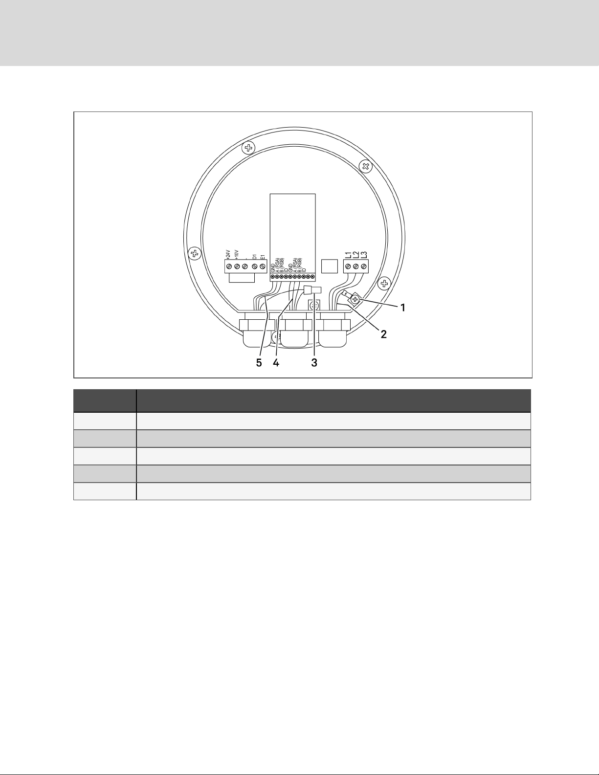
Figure 8.5 Internal wiring of Ziehl-Abegg fan in Condenser
Item Description
1 GND
2 Edge of cable's outer jacket should onlyextend far enough into the enclosure to make the electricalconnections.
3 Not used on last fan.
4 Communication-cable c onnection to the next fan. Not used on last fan.
5 Communication-cable connection from the previous fan or electrical box.
48
Vertiv | Liebert® DSE060™ Installer/User G uide
Page 49
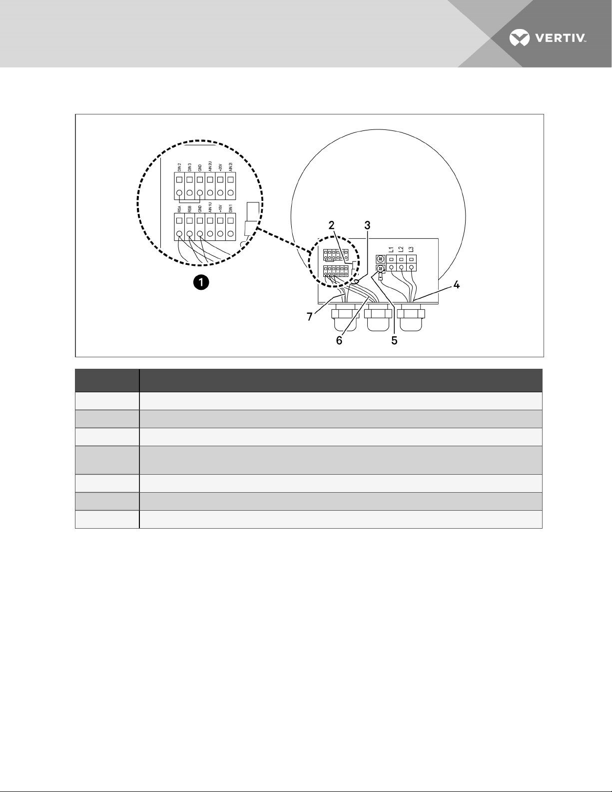
Figure 8.6 Internal wiring of EBM fan in Condenser
Item Description
1 Wiringterminaldetail.
2 Not used on last fan.
3 Must be cable-tied together awayfrom high-voltage terminals
4
5 GND
6 Communication cable connected to the next fan(not used on the last fan).
7 Communication c able from the previous fan or from the electric box.
Edge of out cable jacket should onlyextend far enough into enclosure to be able to make the electrical
connections.
4. Remove hardware that attaches the EC fan to the condenser.
5. Use lifting equipment or an adequate number of personnel to remove the EC fan from the
condenser.
NOTE: A spreader bar may be required for the lifting equipment if only one technician is performing the
fan replacement.
6. Install a spreader bar over the new EC fan if only one technician is performing the fan
replacement.
7. Verify that the wire harness on the new EC fan is secured out of the way before lifting the fan.
8. Verify that the lifting cable/chains are not in contact with fan blades before lifting the new fan
into place on the condenser.
9. Install the new fan in the condenser and connect the mounting hardware.
10. Verify that the fan blades rotate freely when installed in unit.
8 Maintenance
49
Page 50

11. Install the new cable glands included with the new EC Fan. Torque for the cable glands is:
• 630-mm and 710-mm fans: 19.5to24.75 in-lb (2.2 to 2.8 Nm)
• 800-mm fans: 32.75 to 38 in-lb (3.7 to 4.3Nm)
Dispose of the old cable glands once the new glands are installed.
12. Add a compression nut to the wire—Do not tighten the nut.
13. Reconnect the wiring to the proper terminals and verify that the run jumper is in place. See
Figure 8.5 on page48, and Figure 8.6 on the previous page, for wiring details.
• The torque for the electrical terminals is 11.5 in-lb (1.3 Nm). Tighten the compression nut
to a torque of 22 in-lb (2.5 Nm).
14. With the PCB powered, the board display should read F00.
15. Press the ESC button.
16. Press the UP-arrow button once:
• If P- - is displayed, perform step 17.
• if P- - is not displayed, perform steps 18 through 46.
17. If P- - is displayed, press the ENT button to enter the P- - Menu.
The P- - Menu allows compact set-up/preparation of the condenser in the factory or in the
field. Use the functions described in Table 8.3 on the facing page, to establish a default
control configuration for the board.
NOTE: The complete list of P--, C--, and F-- parameters is located inside the lid of the electrical-box
panel.
50
Vertiv | Liebert® DSE060™ Installer/User G uide
Page 51
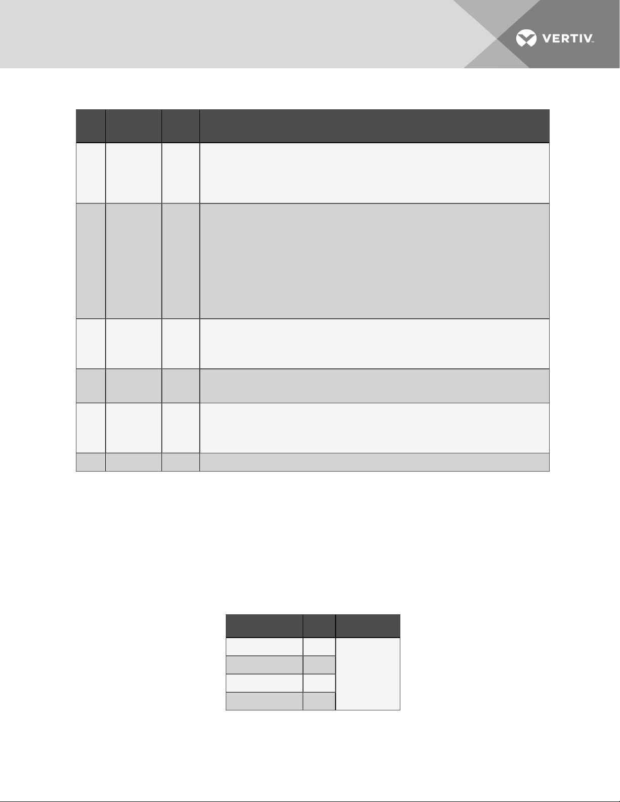
Table 8.3 P-- menu items and definitions
Item
ID
P01
P02
P03
P04
P05
Meaning Default Notes
Enter
Preparation
Mode
Automatic
VSD
Configuration
Refrigerant
Type
Number
of Circuits
Liebert®
Lee Temp
Option
Setting this value to ‘1’ enables preparation mode. All other ‘P—‘menu items are disabled untilthis
value is ‘1’. Note that control operations may be affected during preparation mode, therefore the
0
cooling unit should be off. Setting this value back to ‘0’ creates new default values based upon
selections in this menu. After default values are established, the board exits preparationmode and
reboots.
This item should onlybe used to address the VSDs for the unit. The value entered indicates the
model of the VSD:
1 – EBM
2 – Ziehl-Abegg
1
3 – Fans Tec h
Allfansmust be the same model to use this parameter. When ENT is pressed, the board will
operate and power contactors for the VSDs and assign ModBus addresses. This procedure may
take up to 5minutes to complete.
1 = R22
2
2 = R407C
3 = R410A
1 = Single Circuit
1
2 = DualCircuit
0 = No Lee Temp installed
0
1 = Liebert® Lee-Temp installed
P06 Condenser 1 0 = Small
18. Turn the power On.
19. The control board flashes F00 on the display when it has completed its boot cycle.
20. Press the ESC button.
21. Use the UP or DOWN arrow button until C-- displays.
22. Press the ENT button.
23. Use the UP or DOWN arrow button until C03 displays
24. Press the ENT button.
25. Use the UP or DOWN arrow button to select one of three options:
Configuration Code Fan# Value
C03 Fan 1
C04 Fan 2
C05 Fan 3
C06 Fan 4
0 = No Fan
1 = EBM Papst
2 = Ziehl-Abegg
26. Press the ENT button.
27. If the new value is entered into the control board, the display flashes "888."
8 Maintenance
51
Page 52

28. Press the ESC button to display C03 .
29. Repeat steps 20 through 27 for the remaining fans’ configuration codes, C04, C05 and C06.
30. Unplug all the contactor output plugs except for the fan to be addressed. Plugs are:
• P23 = Fan 1
• P27 = Fan 2
• P28 = Fan 3
• P29 = Fan 4
31. Wait 30 seconds.
32. Use the UP or DOWN arrow button to select one of the following parameters.
The correct parameter depends on the supplier of the fan that will be addressed.
• C00—EBM Papst fan
• C01—Ziehl-Abegg fan
33. Press the ENT button.
34. Use the UP or DOWN arrow button to the correct fan address number. Fan 1 should be 1 (fan
closest to electric panel end). Fan 2 should be 2, etc.
35. Press the ENT button. The display flashes "888 " when the command is accepted.
36. Press the ESC button for the parameter to be shown on the display.
37. Repeat steps 30 through 36 for the rest of the fans that need to be addressed.
38. After the last fan is addressed, unplug the power plug, P24, from the control board, and wait 30
seconds.
39. Plug all the contactor output plugs back into the board in their correct positions.
40. Plug P24 back into the control board.
41. After the control board completes its boot cycle and all the contactors are energized, wait
5seconds.
42. Press the ESC button.
43. Use the UP or DOWN arrow button until A-- is on the display.
44. Press ENT button.
45. Use the UP or DOWN arrow button to see if any of the following errors are shown.
115: Unable to communicate with Fan 1.
215: Unable to communicate with Fan 2.
315: Unable to communicate with Fan 3.
415: Unable to communicate with Fan 4.
• If any of these errors appear, check the communication wiring at the problem fan and the
fan before it.
• If the wiring is correct and properly wired to the terminal, repeat the fan addressing
procedure in steps 30 through 36.
46. If none of the errors listed in step 45 displays, press the ESC button.
52
Vertiv | Liebert® DSE060™ Installer/User G uide
Page 53

8.9.1 Verifing the Fan Address
To verify that each fan has a unique address:
1. Use the UP or DOWN arrow button until C-- displays.
2. Press the ENT button.
3. In the Manual/System Control Selection parameter use the UP or DOWN arrow button until
C24 displays.
4. In the Manual Control configuration parameter, press the ENT button.
5. Use the UP or DOWN arrow button to select 0.
6. Press the ENT button.
The reads "888" if the command is accepted.
7. Press the ESC button to display C24 .
8. Use the UP or DOWN arrow button until C34 displays.
9. Press ENT button.
If Fan 1 is running, the fans speed should display in terms of percentage of full speed. If Fan 1 is
not running, 0.00 should display.
10. Use the UP or DOWN arrow button to enter 100% speed.
11. Press the ENT button.
The display reads "888" if the command is accepted.
• Fan 1 should speed up to 100%, and all the other fans should stay the same speed.
12. If Fan 1 is not running or if any of the other fans also speed up to 100%, steps 30 through 36 of
Replacing the Condenser Fan on page46, must be repeated.
13. Press the ESC button for the parameter to be shown on the display.
14. Repeat steps 3 through 8 for the rest of the fans, if present.
• C35: for Fan 2.
• C36: for Fan 3.
• C37: for Fan 4.
NOTE: All fans should be at 100% speed.
15. Use the UP or DOWN arrow button until C24 displays.
16. Press the ENT button.
17. In the System Control configuration parameter, use the UP or DOWN arrow button to select 1.
18. Press the ENT button.
The display flashes "888" if the command is accepted.
19. Press the ESC button to display C24.
All fans should return to a normal speed based on the pressure input and the state of indoor
unit’s compressor.
8 Maintenance
53
Page 54

Notes on the Premium-efficiency Control Board
• J6 is the CANbus termination jumpers. If the condenser is the last device in the CANbus
communication line, the jumper must be placed between Pins 1 and 2 of J6. If the condenser is
not the last device in the CANbus communication line, then the jumper on J6 must be placed
on Pins2 and 3. CANbus communication errors may occur if the jumpers are not in the correct
positions.
• A jumper must be present at J2. If a jumper is not present, the control board will not boot
properly during power startup.
54
Vertiv | Liebert® DSE060™ Installer/User G uide
Page 55
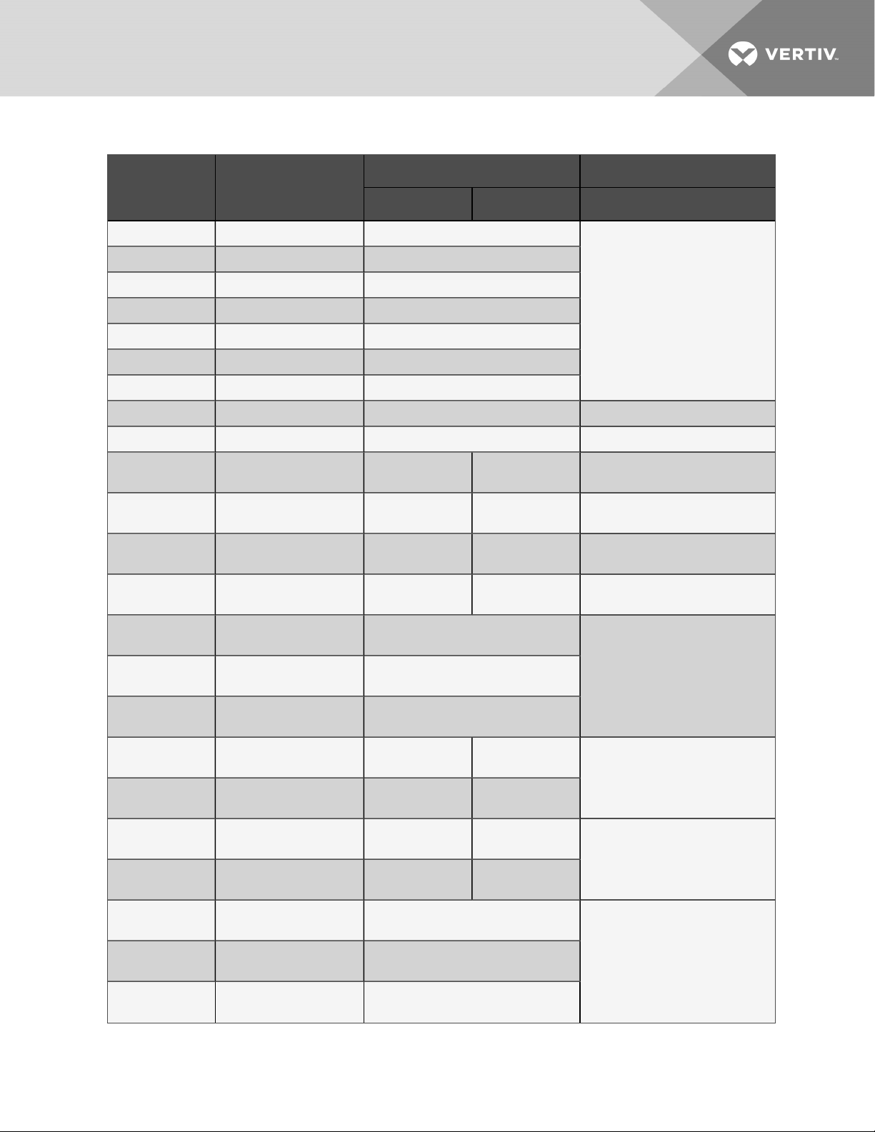
Table 8.4 Premium Efficiency Control Board Configuration-parameter List
Default R410a Comments
Submenu ID Meaning
Metric Imperial
C00 EBM address 1
C01 ZIEHL_ABEGGaddress 1
C02 FANS_TECH address 1
C03 EC Fan1 model ID 0
C04 EC Fan 2 model ID 0
C05 EC Fan 3 model ID 0
C06 EC Fan 4 model ID 0
C07 System model ID 0 "0" = Single, "1" = Dual
C09 System refrigerant type 3 "2" = R407c, "3" = R410a
Do not change unless properly
instructed.
C10
C11
C12
C13
C14
C15
C16
C17
C18
C19
C20
Condenser pressure
absolute max 1
Condenser pressure
absolute max 2
Condenser pressure
absolute min 1
Condenser pressure
absolute min 2
Condenser pressure PID
Kp
Condenser pressure PID
Kip
Condenser pressure PID
Kdp
Refrigerant temperature
max1
Refrigerant temperature
max2
Refrigerant temperature
min 1
Refrigerant temperature
min 2
28.0 bar 406 psi R407c - 17-25 bar; 247-362 psi
28.0 bar 406 psi R410a - 25-38 bar; 363-550 psi
18.0 bar 261 psi R407c - 11-17 bar; 160-246 psi
18.0 bar 261 psi R410a - 16-24 bar; 232-347 psi
1.00
0.02
Do not change unless properly
instructed.
0.00
35°C 95.0°F
Range 30 - 40°C; 86 - 104°F
35°C 95.0°F
25°C 77.0°F
Range 20 - 30°C, 68 - 86°F
25°C 77.0°F
8 Maintenance
C21
C22
C23
Refrigerant temperature
PID Kp
Refrigerant temperature
PID Kip
Refrigerant temperature
PID Kdp
0.36
162.00
1.00
Do not change unless properly
instructed.
55
Page 56
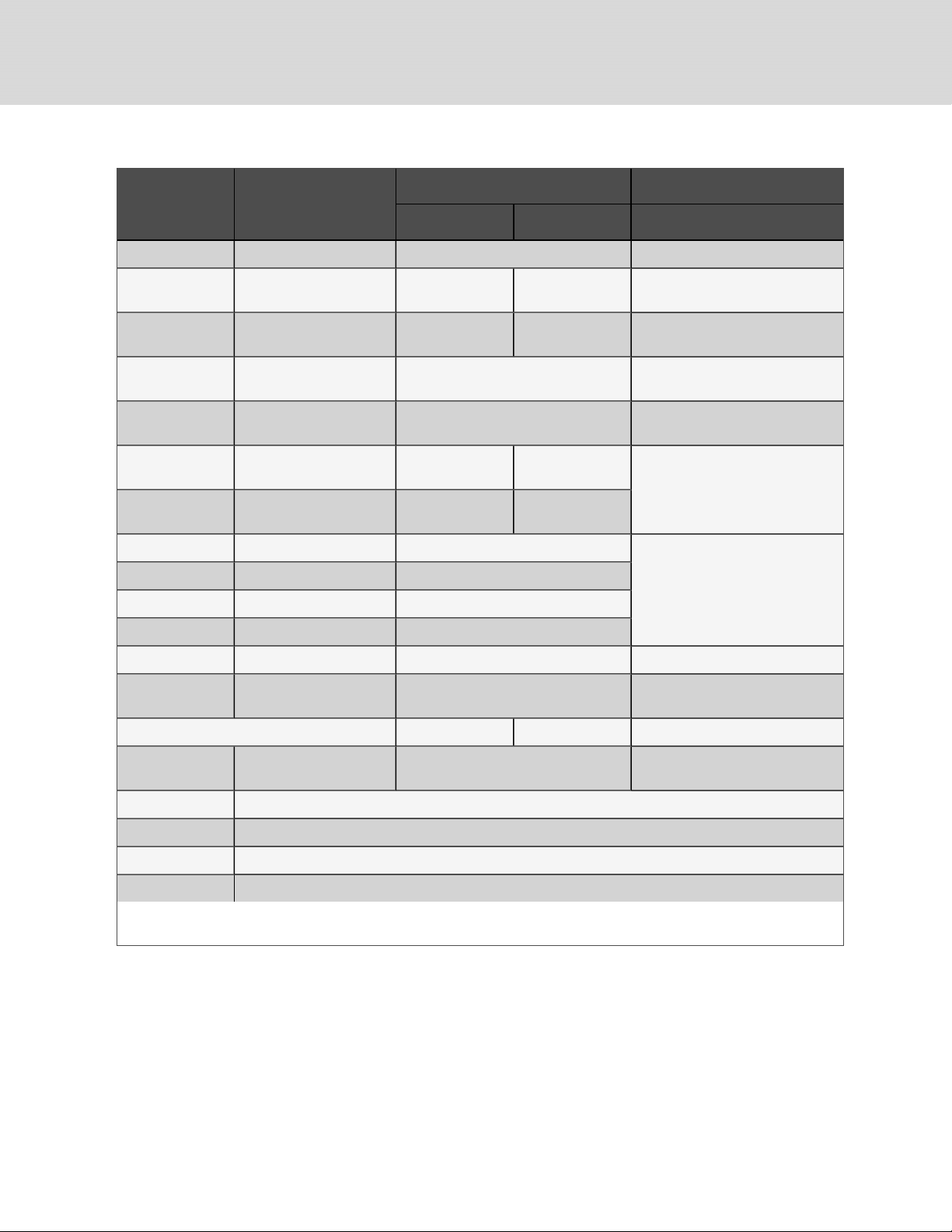
Table 8.4 Premium Efficiency Control Board Configuration-parameter List (continued)
Default R410a Comments
Submenu ID Meaning
Metric Imperial
C24 System control state 1 "0" = Manual, "1" = Auto
C25
C26
C27 Lee Temp Option 0
C28
C32
C33
Condenser pressure
setting point 1
Condenser pressure
setting point 2
Minimum Speed with
LeeTemp
Refrigerant temp. set point
1
Refrigerant temp. set point
2
20.0 bar 290 psi R407c - 12-18 bar; 174-261 psi
20.0 bar 290 psi R410a - 18-26 bar; 261-376 psi
"0" - No Lee Temp installed,
"1" - Lee Temp installed
10% Range 8 - 20%
1.67°C 35°F
Range -40 - +40°C;
-39.9 - +104°F
1.67°C 35°F
C34 EC Fan1 request speed 0%
C35 ECFan2 request speed 0%
C36 EC Fan3 request speed 0%
Manuallysets fan speed (RPM) when
C24 is set to "0".
C37 ECFan4 request speed 0%
C38 ECFan Reverse Request 0 "0" = Off, "1" - On
C39
EC Fan startup speed offset
for pressure mode
0
Offset to the startup speed of the EC
Fan in range -10%to10%
C50-C58
C90 Prefered displayunits. 1
"0" = Metric (bar, °C)
"1" = Imperial(psi, °F)
C91 Save configuration to USB flashdrive. Pressing ENT willexecute the function immediately.
C92 Load c onfiguration from USB flash drive. Pressing ENT willexecute the function immediately.
C98 Clear alarm history.
C99 Restore Factory Defaults except EC fancontrol parameters
Note: Please consult factory before making anychanges to the parameter settings. Changing the parameters without proper
instructions can lead to poor system performance.
56
Vertiv | Liebert® DSE060™ Installer/User G uide
Page 57

8.10 Replacing the Premium-efficiency Control Board
Use these steps to replace the Premium-efficiency Control Board in the condenser.
WARNING! Arc flash and electric shock hazard. Open all local and remote electric power-supply
disconnect switches, verify with a voltmeter that power is Off and wear appropriate,
OSHA-approved personal protective equipment (PPE) per NFPA 70E before working within the
electric control enclosure. Failure to comply can cause serious injury or death. Customer must
provide earth ground to unit, per NEC, CEC and local codes, as applicable. Before proceeding
with installation, read all instructions, verify that all the parts are included and check the
nameplate to be sure the voltage matches available utility power. The Liebert® controller does
not isolate power from the unit, even in the “Unit Off” mode. Some internal components require
and receive power even during the “Unit Off” mode of the controller. The factory-supplied
disconnect switch is on the exterior of the enclosure. The only way to ensure that there is NO
voltage inside the unit is to install and open a remote disconnect switch. Refer to unit electrical
schematic. Follow all local codes.
8.10.1 Preparing to Replace the Board
1. Verify that the following jumpers are installed on the new board (see Figure 8.7 on the next
page):
• Jumper at J4 and J6 on Pins 2 and 3.
• Jumper on J2.
• Jumper on J5 on Pins 1 and 2.
2. Locate the latest revision of the HMI parameters label, 303847P1, included with the new control
board.
NOTE: In Figure 8.7 on the next page, J6 is the CANbus termination jumper. J4 is the RS485 service
termination jumper. If the condenser is the last device in the CANbus communication line, the jumper
must be placed between Pins 1 and 2 of J6. If the condenser is not the last device in the CANbus
communication line, the jumpers on J6 must be placed on Pins 2 and 3. If the jumper is not in the
correct positions, CANbus communication errors may occur. The jumper on J4 will always be placed
between Pins 1 and 2.
NOTE: In Figure 8.7 on the next page, a jumper must be present at J2. If a jumper is not present, the
control board will not boot properly during power startup.
8 Maintenance
57
Page 58
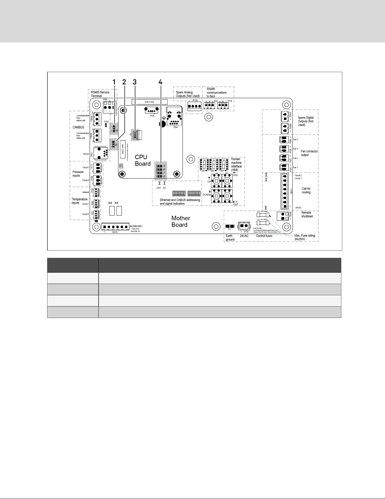
Figure 8.7 Jumper locations on Control Board
Item Description
1 J4, RS485 service termination jumper
2 J6, Canbus termination jumper
3 J5
4 J2
58
Vertiv | Liebert® DSE060™ Installer/User G uide
Page 59

8.10.2 Installing the Replacement Board
WARNING! Arc flash and electric shock hazard. Open all local and remote electric power-supply
disconnect switches, verify with a voltmeter that power is Off and wear appropriate,
OSHA-approved personal protective equipment (PPE) per NFPA 70E before working within the
electric control enclosure. Failure to comply can cause serious injury or death. Customer must
provide earth ground to unit, per NEC, CEC and local codes, as applicable. Before proceeding
with installation, read all instructions, verify that all the parts are included and check the
nameplate to be sure the voltage matches available utility power. The Liebert® controller does
not isolate power from the unit, even in the “Unit Off” mode. Some internal components require
and receive power even during the “Unit Off” mode of the controller. The factory-supplied
disconnect switch is on the exterior of the enclosure. The only way to ensure that there is NO
voltage inside the unit is to install and open a remote disconnect switch. Refer to unit electrical
schematic. Follow all local codes.
1. Turn Off the disconnect switch on the condenser enclosure cover.
2. Open the control enclosure cover.
3. Manually turn On the disconnect switch.
NOTE: Power is On and a shock hazard exists with exposure to hazardous voltage components.
4. If the board can still be powered up and has a display, record the parameter settings.
• To obtain parameters go to the C-- menu and press the UP or DOWN arrow button to
read and record the values for C03-09 and C27.
5. Record all of the DIP switch positions for the CANbus DIP switch package. Retain these for
setting up the new board.
6. Record the positions of the jumpers for J2, J4, J5 and J6 on control board in the unit. Retain
these for setting up the new board.
7. Disconnect power from the condenser by turning Off the main disconnect switch.
8. Use a voltmeter to verify that voltage is no longer present in the unit.
9. Remove the plugs and field-installed wires from the old board. Note the polarity for the
CANbus wiring going to P49 and P50, if present.
10. Mark wires P49-1, P49-3, etc, if they are not already marked.
11. Remove the mechanical fasteners holding the control board in place and remove the old
control board.
12. Install the new control board using the fasteners removed in step 11.
13. Reattach the plugs. Refer to the hot-stamps on the wire harnesses that correspond to the
correct plug on the board. Verify that the plugs are installed properly.
14. Change the CANbus DIP switch positions so they match the control board that was removed. If
the condenser is the second condenser on the CANbus communication line, set Position 1 of
the CANbus DIP switch from On to Off.
15. Change the jumper positions for J2, J4, J5 and J6 to match the control board that was
removed. If the condenseris the last device on the CANbus communication line, move the
jumper at J6 from Pins2 and 3 to Pins 1 and 2 (see Figure 8.7 on the previous page).
16. Power up the unit.
8 Maintenance
59
Page 60

17. Change the parameters to match the parameters from the control board that was removed if
they were obtained from the old board in step 4. See step 18 if the parameters were unavailable.
18. If the old board parameters were unavailable, use the new HMI label included in kit to obtain
the proper settings. Parameters C03, C04, C05 and C06 must be programmed with the proper
EC fan supplier used on the unit.
19. Address the fans (refer to Replacing the Condenser Fan on page46).
20. Compare the HMI label on the unit with the latest revision.
• If there are differences, clean and dry the surface of the old HMI label; attach the new
label on top of the old label, covering the old label with the new one.
21. Verify that the control board is reading pressure and temperature.
22. Verify that there are no communication alarms with the fans or with the cooling unit the
condenser is serving.
23. Verify proper fan operation by adjusting the cooling unit that this condenser serves so that it
calls for cooling.
8.11 Pumped-refrigerant Economizer (PRE)
Your Liebert® DP060 includes a Liebert® PRE system. Refer to the Installer/User Guide for the economizer,
SL-18920, for the maintenance and operation details.
60
Vertiv | Liebert® DSE060™ Installer/User G uide
Page 61

9 PREVENTIVE MAINTENANCE CHECKLIST
Inspection Date Job Name
Unit Model # Unit Serial Number #
Room Temperature/Humidity °% Ambient Temperature °
Not all units will have all components. To determine your unit’s configuration, compare the Unit Model #
above above and the information in the Components and Nomenclature section.
Good maintenance practices are essential to minimizing operation cost and maximizing product life. Read
and follow all applicable maintenance checks listed below. At a minimum, these checks should be
performed semi-annually. However, maintenance intervals may need to be more frequent based on sitespecific conditions. Review the unit user manual and the iCOM user manual (SL-31075) for further
information on unit operation. We recommend the use of trained and authorized service personnel,
extended service contracts, and factory-certified replacement parts. Contact your local sales
representative for more details.
Check all that apply:
Evaporator/Filters
1. Check/Replace filters
2. Wipe section clean
3. Coil clean
4. Clean condensate pan
5. Check/Test filter-clog switch operation
Blower Section (evaporator fans)
1. Mounting bolts tight
2. Blower wheels free of debris and spins freely
3. Check motor mount
4. Check/Test air sail switch
5. Motor amp draw
• Compare to nameplate amps
#1 L1 L2 L3
Electrical Panel
1. Check fuses
2. Check contactors for pitting (Replace if pitted)
3. Check/Re-torque wire connections
Controls
1. Check/Verify control operation (Sequence)
2. Check/Test changeover device(s) (if equipped)
9 Preventive Maintenance Checklist
61
Page 62

Compressors
1. Check oil level
2. Check for oil leaks
3. Check compressor mounts (bushings)
4. Cap tubes (not rubbing)
5. Check/Re-torque wire connections (inside compressor box)
6. Compressor operation (vibration/noise)
7. Check crank-case heater fuses/operation (if equipped)
8. Check for refrigerant leaks
15. Amp draw
Circuit #1 L1 L2 L3
Condenser
9. Suction pressure Circuit #1
10. Discharge Pressure Circuit #1
11. Superheat Circuit #1
12. Low-pressure switch cut out Circuit #1
13. Low pressure cut in Circuit #1
14. High pressure cut out Circuit #1
1. Coil clean
2. Fans free of debris
3. Fans securely mounted
4. Motor bearings in good condition
5. Check all refrigerant lines for vibration isolation. Support as necessary
6. Check for refrigerant leaks
7. Check surge-protection device (if installed) status-indicator lights
8. Check/Re-torque wire connections
9. Check contactors for pitting (replace if pitted)
10. Verify operation sequence/set points
11. Charge verification:
a. Outdoor Ambient Temperature__________
b. Subcooling__________
c. Indoor-unit Return-air Temperature__________
d. Sight-glass level (if Lee-Temp or pumped refrigerant)_________
12. Motor amp draw
#1 L1 L2 L3
#2 L1 L2 L3
#3 L1 L2 L3
#4 L1 L2 L3
62
Vertiv | Liebert® DSE060™ Installer/User G uide
Page 63

Pumped-refrigerant Economizer
1. Check for refrigerant leaks
2. Check/Re-torque wire connections
3. Check contactors for pitting (replace if pitted)
4. Verify pump-speed control operation
5. Check pump mounting
9 Preventive Maintenance Checklist
63
Page 64

MAINTENANCE NOTES
Name
Signature
Company
Make photocopies for your records. Compare readings/information to previous maintenance worksheet.
64
Vertiv | Liebert® DSE060™ Installer/User G uide
Page 65

To locate your local Vertiv representative for Vertiv-engineered parts, check
https://www.vertivco.com/en-us/support/ or Call 1-800-543-2778.
9 Preventive Maintenance Checklist
65
Page 66

This page intentionally left blank
66
Vertiv | Liebert® DSE060™ Installer/User G uide
Page 67

APPENDICES
Appendix A: Technical Support and Contacts
A.1 Technical Support/Service in the United States
Vertiv™ Corporation
24x7 dispatch of technicians for all products.
1-800-543-2378
Liebert® Thermal Management Products
1-800-543-2778
Liebert® Channel Products
1-800-222-5877
Liebert® AC and DC Power Products
1-800-543-2378
A.2 Locations
United States
Vertiv Headquarters
1050 Dearborn Drive
Columbus, OH, 43085, USA
Europe
Via Leonardo Da Vinci 8 Zona Industriale Tognana
35028 Piove Di Sacco (PD) Italy
Asia
7/F, Dah Sing Financial Centre
3108 Gloucester Road
Wanchai, Hong Kong
67
Page 68

This page intentionally left blank
68
Vertiv | Liebert® DSE060™ Installer/User G uide
Page 69
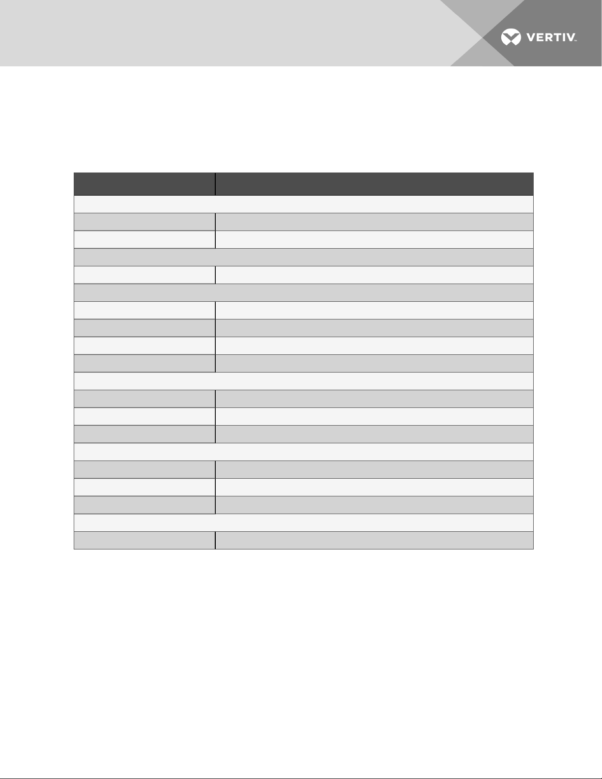
Appendix B: Submittal Drawings
The submittal drawings are in the order of document part number (DPN). Table B.1 below, groups the
drawings by topic/application.
Table B.1 Submittal-drawings Contents
Document Number Title
Air-flow Diagrams
DPN004598 Perimeter unit air flow
DPN004599 Evaporator Ducting DimensionalData
Component Locations
DPN004597 Component Location, Perimeter Unit
Planning Dimensions
DPN004600 Cabinet and Anchor DimensionalData
DPN004601 Condensate-drain Access and Location
DPN004756 Installation andService Clearance for Multiple Units
DPN004602 Evaporator Compartment Service Area
Electrical Connections
DPN004587 Electrical Connections Enclosure, Dualpower input
DPN004732 Electrical Connections Enclosure, Single power input
DPN004591 Evaporator Electrical Panel component definitions and locations
iCOM-control Details
DPN004350 Liebert® iCOM Unit-mounted Display
DPN000960 Liebert® iCOM Remote temperature and humidity sensor
DPN003144 Liebert® iCOM Service bracket
Unit-to-Unit Networking
DPN004351 Liebert®iCOM Unit-to-unit Network Connections
69
Page 70

This page intentionally left blank
70
Vertiv | Liebert® DSE060™ Installer/User G uide
Page 71
LIEBERT iCOM™
REMOTE TEMPERATURE & HUMIDITY SENSOR
4 1/4"
108mm
Plug in Cable to
Either Connector
4 5/16"
109mm
Front View
Circuit Board
Max Depth
1 11/16
( 42mm )
Always Mount Housing
as Shown
5/8"
15mm
1 1/2"
38mm
Plug in Cable to
Connector Marked P67
Back View
3 1/8"
81mm
Cable Raceways
Shielded Cable
Unit End
Plug
Secure Ground Wire
with screw to Back of
Electric Box
1/2"
13mm
1 1/2"
38mm
Remote Temp & Humid
Sensor Box
DPN000960
Page :1 /1
Form No.: DPN001040_REV4
Inside View of Back
Cable Marked
"Sensor End"
Board Clip
Locator Pins
Front and Back Sections
Snap Together at 4 Locations
Board Clip
Alternate Cable Entrance
for Upflow Models
Liebert Room Unit
(unit size varies per product line)
Factory supplied, field installed
shielded cable. See specification
sheet for length.
P67
Cable Marked
"Unit End"
Route Cable through
Designated Holes in Unit
for Low Voltage Field Wiring
Cable Entrance for
Downflow Shown
REV : 3
REV DATE : 3/17
Page 72
6"
PURPOSE:
152mm
LIEBERT iCOM™
DISPLAY SERVICE BRACKET (OPTIONAL)
1 1/4"
32mm
7 1/4"
184mm
studs
Bracket
Bracket with
Touch Screen
between service tasks.
STEPS:
1) Verify that unit vertical panels are in place.
2) Unlatch display from cradle by pinching top tab while holding back of display - careful not to drop or let
display hang by cables.
3) Align studs of bracket with keyholes on back of display.
4) Compress bracket and display at stud points together until bracket studs slide into slots of keyholes - careful
not to pinch cables. There should be a tight fit once bracket is in place.
5) Hold display in hand to make adjustments.
6) Hang from lower edge of low voltage compartment between service tasks.
7) After use, remove and store bracket in tool box (do not store in electric panel).
8) Return Liebert iCOM™ display to cradle/bezel assembly.
DPN003144
Page :1 /1
Form No.: DPN001040_REV4
Liebert Room Unit with Bracket & Display
(unit size varies per product line)
Bracket with display assembly may be hand held for adjustments. Bracket enables hanging the display
REV : 3
REV DATE : 7/17
Page 73
LIEBERT iCOM™
PRODUCT INFORMATION
UNIT MOUNTED DISPLAY
The Liebert iCOM™ display is a 7-inch capacitive, color-touchscreen display in an ergonomic, aesthetically
pleasing housing. The display and housing will be viewable while the unit accent panels are open or closed.
The display can be easily detached to view while the panel is open.
Menu Layout- The menus will be broken out into two main menu screens: User screen and Service screen.
The User screen contains the menus to access parameters required for basic unit control and setup.
The Service screen is designed for service personal and provides access to advanced control setup features
and diagnostic information.
Password Protection- The display will contain two unique passwords to protect against unauthorized changes.
An auto hide/show feature allows the user to see applicable information based on the login used. These four-digit
passwords may be customized according to User preference.
Parameter Search- The display has search fields for efficient navigation and parameter lookup.
Form No.: DPN001040_REV4
DPN004350
Page :1 /3
REV : 1
REV DATE : 8/18
Page 74

LIEBERT iCOM™
Context Sensitive Help
- The display will have an onboard help database. The database will provide context
functionality (Tea
mwork modes, sharing sensor data, Standby Rotation, Lead
-
Lag, and
Cascade operation).
PRODUCT INFORMATION
UNIT MOUNTED DISPLAY
sensitive help to assist with setup and navigation of the menus.
Display Setup- The user has the ability to configure the display information based on the specific user’s preference.
Language, units of measure, screen contrast, home screen layout, back light timer and the hide/show of certain
readouts will be configurable through the display.
Additional Readouts- The display has the ability for the user to configure custom widgets on the main screen.
Widget options will include items such as fan speed, call for cooling, call for free cooling, maintenance status,
call for hot water reheat, call for electric reheat, call for dehumidification, call for humidification, airflow, static pressure,
fluid flow rate and cooling capacity.
Status LEDs- The display will provide the user with the unit’s operating status using an integrated LED.
The LED will indicate if the unit has an active alarm; if the unit has an active alarm that has been acknowledged;
or if the unit is on, off, or in a standby status.
Unit Alarms – All unit alarms are annunciated through both audio and visual cues, clearly displayed on the screen,
automatically recorded in the event log, and communicated to monitoring plug connections.
Event Log – The display will automatically store the last 400 unit-only events (messages, warnings, and alarms).
Service Contact Information – The display has the ability to store the local service or sales contact information.
Upgradeable –Display and Control Board software upgrades are performed through a USB connection.
Unit-to-Unit (U2U) Communication – Communication via private Ethernet network allows for advanced control
DPN004350
Page :2 /3
Form No.: DPN001040_REV4
REV : 1
REV DATE : 8/18
Page 75

LIEBERT iCOM™
component problems before
vice terminal. Each control output shall be indicated
PRODUCT INFORMATION
UNIT MOUNTED DISPLAY
Parameter Directory- The Liebert iCOM shall provide a directory that lists all parameters in the control.
The list shall provide Line ID numbers, parameter labels, and current parameter values.
Timers/Sleep Mode- The menus shall allow various customer settings for turning the unit On or Off.
Sensor Calibration- The menus shall allow unit sensors to be calibrated with external sensors.
Maintenance/Wellness Settings- The menus shall allow reporting of potential
they occur.
Options Setup- The menus shall provide operation settings for the installed components.
Auxiliary Boards- The menus shall allow setup of optional expansion boards.
Various Sensors: The menus shall allow setup and display of optional custom sensors. The control shall
include four customer accessible analog inputs for field-supplied sensors. The analog inputs shall accept a
4 to 20mA signal. The user shall be able to change the input to 0 to 5VDC or 0 to 10VDC. The gains for
each analog input shall be programmable from the front display. The analog inputs shall be able to be
monitored from the front display.
Diagnostics/Service Mode- The Liebert iCOM control shall be provided with self-diagnostics to aid in
troubleshooting. The microcontroller board shall be diagnosed and reported as pass/not pass. Control
inputs shall be indicated as On or Off at the front display. Control outputs shall be able to be turned On or
Off from the front display without using jumpers or a ser
by an LED on a circuit board.
DPN004350
Page :3 /3
Form No.: DPN001040_REV4
REV : 1
REV DATE : 8/18
Page 76
LIEBERT DS, DSE, CW, PDX & PCW
TB3
P
UNIT TO UNIT NETWORK CONNECTIONS
RS485
SITE AND BMS
COMMUNICATION
ETHERNET
CONNECTIONS
+
1 2
-
A
TB3
P75
P95 DVI-D CABLE CONNECTION
TO 7-INCH ICOM DISPLAY
P71 P72
P76
P95
P74 P64
iCOM
MICROPROCESSOR
AND I/O BOARD
P100
E5
7
6
P
6
6
P
1
2
1
1
P
P
0
1
2
2
P
P
3
1
P
7
P
P100 POWER SUPPLY TO
7-INCH ICOM DISPLAY
DETAIL A
ETHERNET CABLE
(FIELD SUPPLIED)
UNIT-TO-UNIT NETWORKING SWITCH
(FIELD SUPPLIED)
TO / FROM OTHER
NETWORKED UNITS
Form No.: DPN001040_REV4
DPN004351
Page :1 /2
REV : 2
REV DATE : 6/18
Page 77
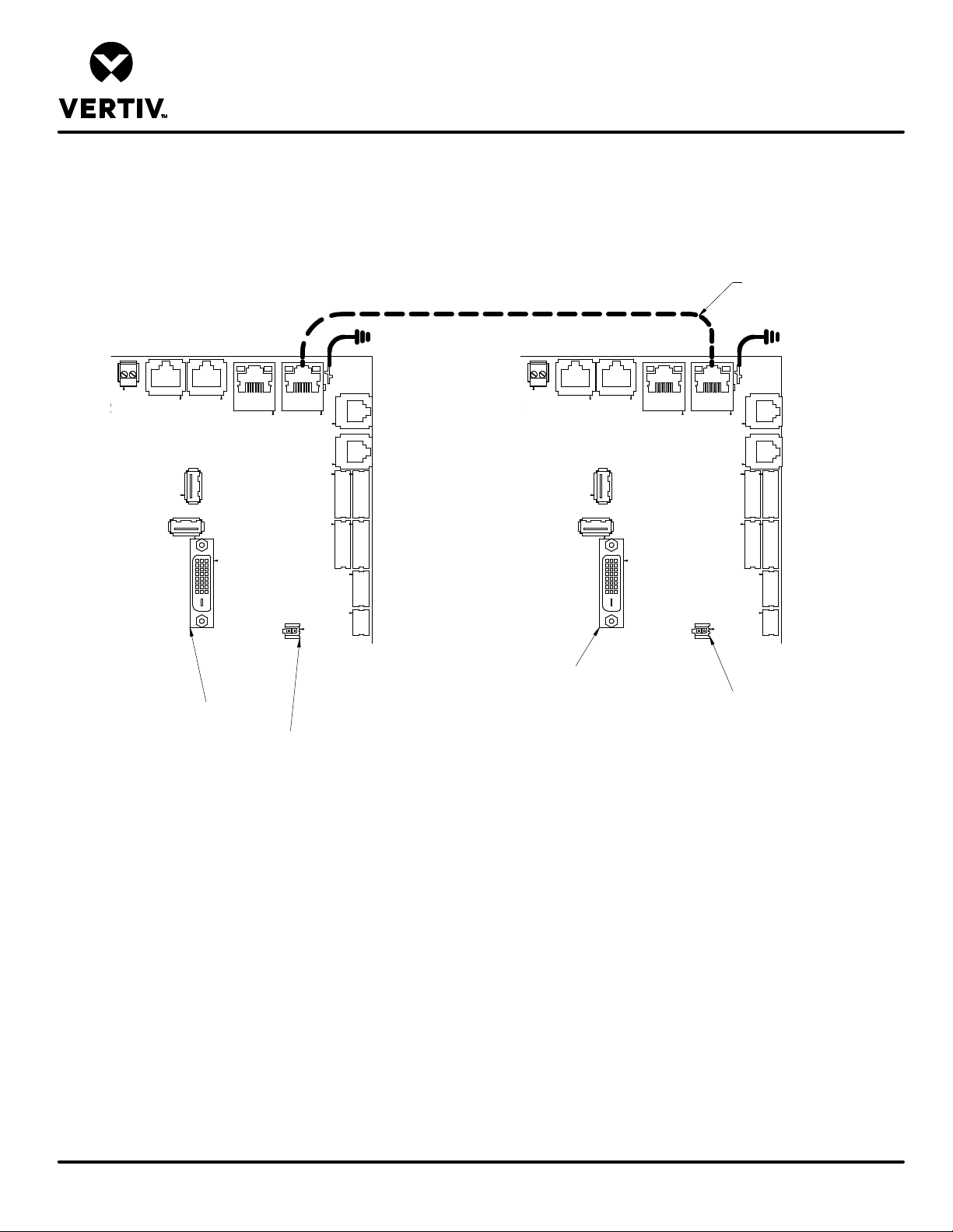
LIEBERT DS, DSE, CW, PDX & PCW
UNIT TO UNIT NETWORK CONNECTIONS
ETHERNET CABLE
(FIELD SUPPLIED)
P71
TB3
P76
P75
P95
P95 DVI-D CABLE CONNECTION
TO 7-INCH ICOM DISPLAY
P72
P74 P64
MICROPROCESSOR
AND I/O BOARD
E5
iCOM
P100
P100 POWER SUPPLY TO
7-INCH ICOM DISPLAY
P72
P71
7
6
P
6
6
P
2
1
1
1
P
P
1
0
2
2
P
P
3
1
P
7
P
P95 DVI-D CABLE CONNECTION
TO 7-INCH ICOM DISPLAY
TB3
P76
P75
P95
P74 P64
iCOM
MICROPROCESSOR
AND I/O BOARD
P100
E5
7
6
P
6
6
P
1
2
1
1
P
P
0
1
2
2
P
P
3
1
P
7
P
P100 POWER SUPPLY TO
7-INCH ICOM DISPLAY
Form No.: DPN001040_REV4
DPN004351
Page :2 /2
NOTE* For dual-unit network configurations only
REV : 2
REV DATE : 6/18
Page 78

LIEBERT DSE
tion. 1 AMP, 24VAC
Terminals for the connection of a field supplied 120V 20A utility power to feed the light and
On any alarm, two additional normally open contacts are closed across terminals 94 & 95 and 96 & 97 for
n contactor, normally open dry contact is closed across terminals 84 & 85
ELECTRICAL FIELD CONNECTIONS
DP060 UNIT DEFINITIONS AND LOCATIONS
DUAL POWER INPUT
STANDARD ELECTRICAL CONNECTIONS
1) HIGH VOLTAGE ENTRANCE – This area will be used for the high voltage fittings. Enclosure is not provided with holes or knockouts,
which must be done by the installer in the field. The fittings used must have the proper environmental rating per code.
2) LOW VOLTAGE ENTRANCE – This area will be used for the low voltage and communication fittings. Enclosure is not provided with
holes or knockouts, which must be done by the installer in the field. The fittings used must have the proper environmental rating per
code.
3) HIGH VOLTAGE WIRE DUCT – Wire duct to be used by the installer for high voltage wire routing.
4) SOURCE 1 MAIN UNIT POWER CONNECTIONS – Terminals are located on top of the locking disconnect switch. See side of
disconnect switch for wire range and tightening torque. Three phase service not provided by Liebert. Wire range and tightening torque
will vary based on disconnect size. Refer to label on side of disconnect.
5) EARTH GROUND CONNECTION FOR SOURCE 1 MAIN UNIT POWER – Terminal for field supplied Source 1 earth grounding wire.
Earth grounding required for Liebert units. 14-2AWG wire range, 275 in-lb wire tightening torque.
6) SOURCE 2 MAIN UNIT POWER CONNECTIONS - Terminals are located on top of the locking disconnect switch. See side of
disconnect switch for wire range and tightening torque. Three phase service not provided by Liebert. Wire range and tightening torque
will vary based on disconnect size. Refer to label on side of disconnect.
7) EARTH GROUND CONNECTION FOR SOURCE 2 MAIN UNIT POWER - Terminal for field supplied Source 2 earth grounding wire.
Earth grounding required for Liebert units. 14-2AWG wire range, 275 in-lb wire tightening torque.
8) REMOTE SHUTDOWN - Replace existing jumper between terminals 37 & 38 with field supplied normally closed switch having a
minimum 75VA, 24VAC rating. Use field supplied Class 1 wiring.
9) CUSTOMER ALARM INPUTS – Terminals for field supplied, normally open contacts, having a minimum 75va, 24vac rating, between
terminals 24 & 50, 51, 56. Use field supplied Class 1 wiring. Terminal availability varies by unit options.
10) COMMON ALARM – On any alarm, normally open dry contact is closed across terminals 75 & 76 for remote indica
max load. Use Class 1 field supplied wiring.
11) REMOTE HUMIDIFIER – On any call for humidification, normally open dry contact is closed across terminals 11 & 12 to signal field
supplied remote humidifier. 1 AMP, 24VAC max load. Use Class 1 field supplied wiring.
12) FIELD SUPPLIED 120V UTILITY POWER –
service electrical outlet. 22-8AWG wire range, 14.2lb-in tightening torque.
13) EARTH GROUNDING CONNECTION FOR FIELD SUPPLIED 120V UTILITY POWER - Terminal for field supplied 120V earth
grounding wire. Earth grounding required for Liebert units. 14-2/0AWG wire range, 14-8AWG – 75lb-in, 6-4AWG – 110lb-in, 2-1AWG –
150lb-in, 1/0 – 2/0AWG – 180lb-in.
LOW VOLTAGE TERMINAL PACKAGE CONNECTIONS
14) EXTRA REMOTE UNIT SHUTDOWN – Two additional contact pairs available for unit shutdown (labeled as 37B & 38B, 37C & 38C).
Replace jumpers with field supplied normally closed switch having a minimum 75VA, 24VAC rating. Use field supplied Class 1 wiring.
15) EXTRA COMMON ALARM –
remote indication. 1 AMP, 24VAC max load. Use Class 1 field supplied wiring.
16) MAIN FAN AUXILIARY SWITCH – On closure of the main fa
for remote indication. 1 AMP, 24VAC max load. Use Class 1 field supplied wiring.
17) LIQUITECT SHUTDOWN AND DRY CONTACT – On LiquiTect activation, normally open dry contact is closed across terminals 58 &
59 for remote indication (LiquiTect sensor ordered separately). 1 AMP, 24VAC max load. Use Class 1 field supplied wiring.
NOTE: All low voltage terminal connections are spring-cage with a wire range of 28-12AWG.
NOTE: Items 11 and 12 may not be present if Unit supplier 120V utility option is selected.
DPN004587
Page :1 /3
Form No.: DPN001040_REV4
REV : 1
REV DATE : 1/19
Page 79

LIEBERT DSE
Use shielded
Refer to specification sheet for total unit full load amps, wire size amps, and max overcurrent protection device size.
ELECTRICAL FIELD CONNECTIONS
DP060 UNIT DEFINITIONS AND LOCATIONS
DUAL POWER INPUT
STANDARD COMMUNICATION CONNECTIONS
18) RS485 BMS CONNECTION – Terminal TB3-1 is TX/RX+. Terminal TB3-2 is TX/RX-. Terminal TB3-3 is earth ground.
cable with 120ohm characteristic impedance. (Supplied by other).
19) CANBUS REMOTE SENSOR CONNECTION(P67) – Remove the inserted plug from this connector and attach the remote sensor
cable to power and communicate with Liebert remote Temperature/humidity sensors. Use shielded cable with 120ohm characteristic
impedance. (Supplied by other).
20) ETHERNET BMS CONNECTION(P74) – RJ-45 connection for connecting to BMS Ethernet network. Use Class 5 shielded cable
(Supplied by other).
21) ETHERNET UNIT TO UNIT CONNECTION(P64) – RJ-45 connection for connecting to other units. Use Class 5 shielded cable
(Supplied by other).
NOTE: All low voltage terminal connections are spring-cage with a wire range of 28-12AWG.
NOTE: All communication cables should be kept separate from high-voltage wiring.
OPTIONAL ELECTRICAL CONNECTIONS
22) SMOKE SENSOR ALARM – Factory wired dry contacts from smoke sensor are 91-common, 92-Normally Open, and 93-Normally
Closed. Supervised contacts, 80 & 81, open on sensor trouble indication. This smoke sensor is not intended to function as, or
replace, any room smoke detection system that may be required by local or national codes. 1 AMP, 24VAC max load. Use Class 1
field supplied wiring.
23) CONDENSATE ALARM – On pump high water indication, normally open dry contact is closed across terminals 88 & 89 for remote
indication. 1 AMP, 24VAC max load. Use Class 1 field supplied wiring.
NOTE: Terminals for item 22 and 23 are always present. Refer to the order to verify if the options are installed on the unit.
DPN004587
Page :2 /3
Form No.: DPN001040_REV4
REV : 1
REV DATE : 1/19
Page 80
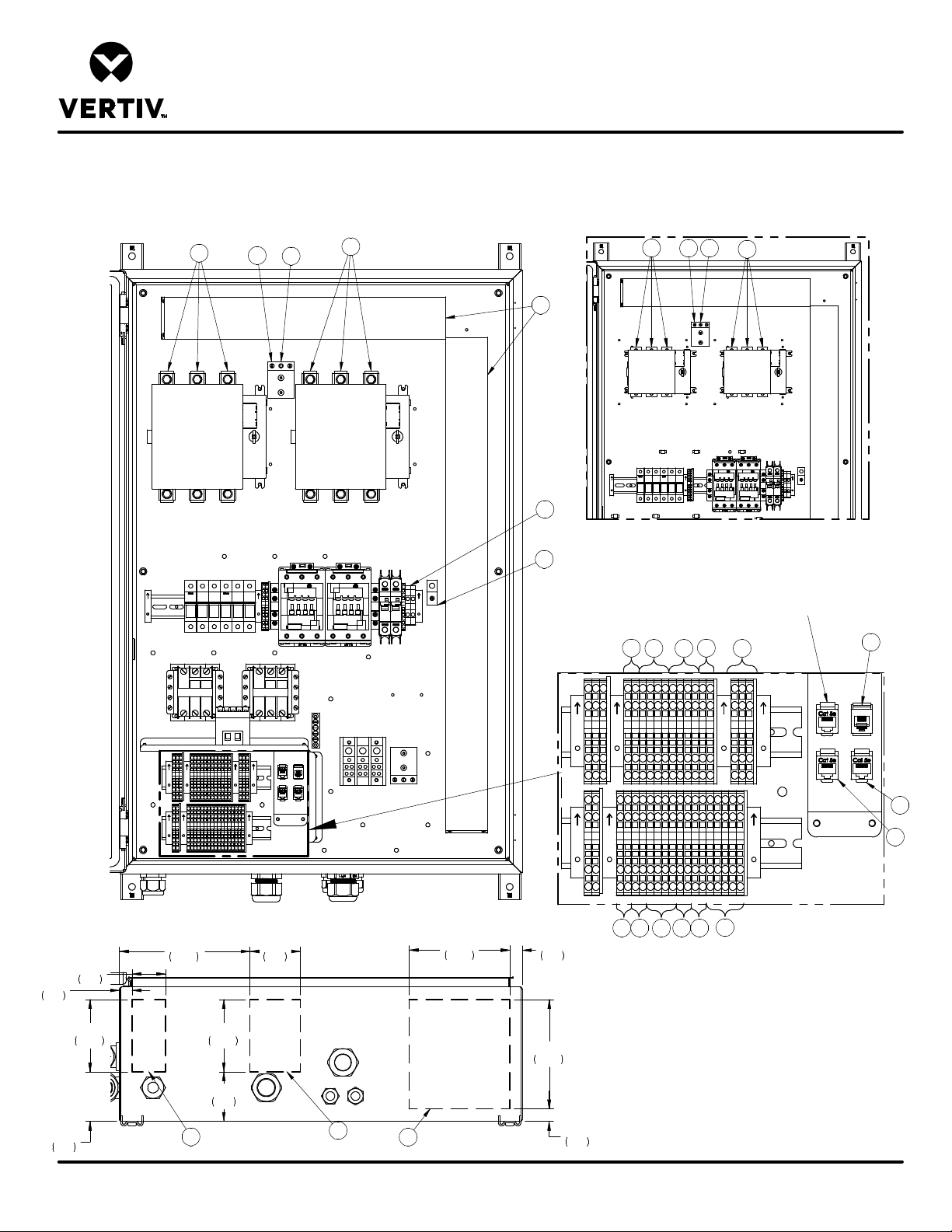
LIEBERT DSE
ELECTRICAL FIELD CONNECTIONS
DP060 UNIT DEFINITIONS AND LOCATIONS
DUAL POWER INPUT
4
5
7
6
3
12
4
5 7
6
3/4"
19
13
200A DISCONNECT VIEW
7 3/4"
2"
51
197
3"
76
FRONT
6"
152
3/4"
19
FOR REFERENCE
8 11
14 9 18
17 10
16 23
15
FACTORY USE ONLY
19
21
20
22
60A DISCONNECT VIEW
Form No.: DPN001040_REV4
4 1/4"
109
3"
75
DPN004587
Page :3 /3
4 1/4"
109
3"
75
2
2
1
BACK
BOTTOM VIEW
6 1/2"
165
3/4"
19
REV : 1
REV DATE : 1/19
Page 81
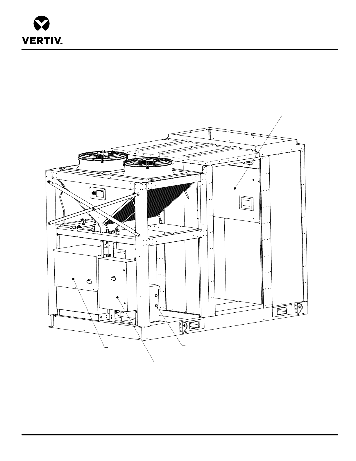
LIEBERT DSE
DP060 ENCLOSURE ELECTRICAL LOCATIONS
EVAPORATOR
ELECTRIC PANEL
(SIDE ENTRANCE DOOR
REMOVED FOR CLARITY)
Form No.: DPN001040_REV4
DPN004591
Page :1 /5
CONDENSER AND
ECONOPHASE
ELECTRIC
PANEL
UNIT TRANSFORMER
(208V, 240V, & 575V)
CUSTOMER CONNECTION
ELECTRIC PANEL
(SINGLE POWER INPUT SHOWN)
REV : 1
REV DATE : 7/18
Page 82
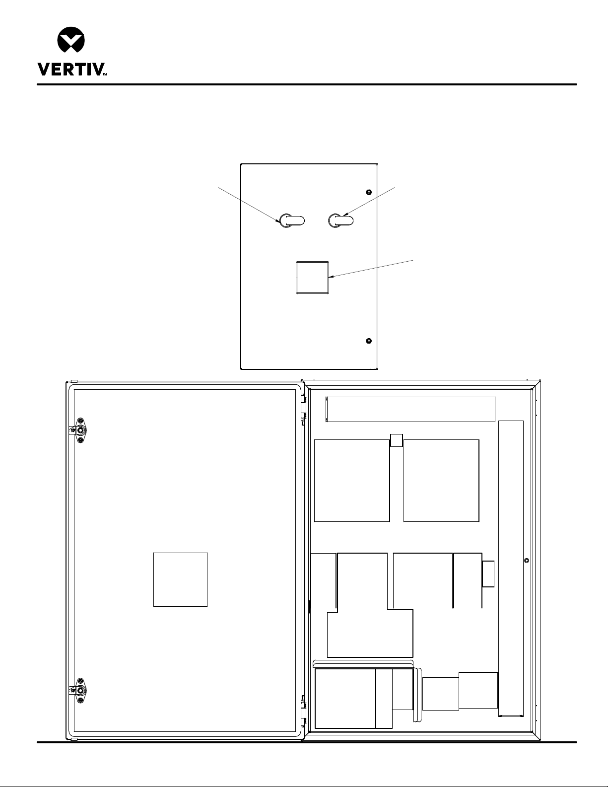
LIEBERT DSE
DP060 CUSTOMER CONNECTION ELECTRICAL PANEL
COMPONENT DEFINITIONS AND LOCATIONS
DUAL POWER INPUT
DISCONNECT HANDLE
SOURCE 1
FUSED DISCONNECT
SOURCE 1
SOURCE 2
DISCONNECT HANDLE
TRANSFER
CONTROLLER
WIRE
DUCT
GND
LUG
FUSED DISCONNECT
SOURCE 2
Form No.: DPN001040_REV4
DPN004591
Page :2 /5
ATS
CONTROLLER
POWER
METER,
POWER
ATS CONTROLLER
FUSES
(OPTIONAL)
TRANSFORMERS,
RELAYS,
AND GND BAR
LOW VOLTAGE TERMINALS
CUSTOMER CONNECTIONS
120V
UTILITY
GND
LUG
120V UTILITY
CIRCUIT
UNIT
FUSES
208V, 230V, &
575V UNITS
BREAKERS
AND
TERMINALS
(OPTIONAL)
POWER
DISTRIBUTION
BLOCK
AND GND
DISTRIBUTION
LUG
CHANGE-OVER
CIRCUIT
CONTACTORS
TRANSFORMER
CONNECTORS
COMMUNICATION
ETHERNET SWITCH
FIVE PORT (OPTIONAL)
WIRE
DUCT
REV : 1
REV DATE : 7/18
Page 83
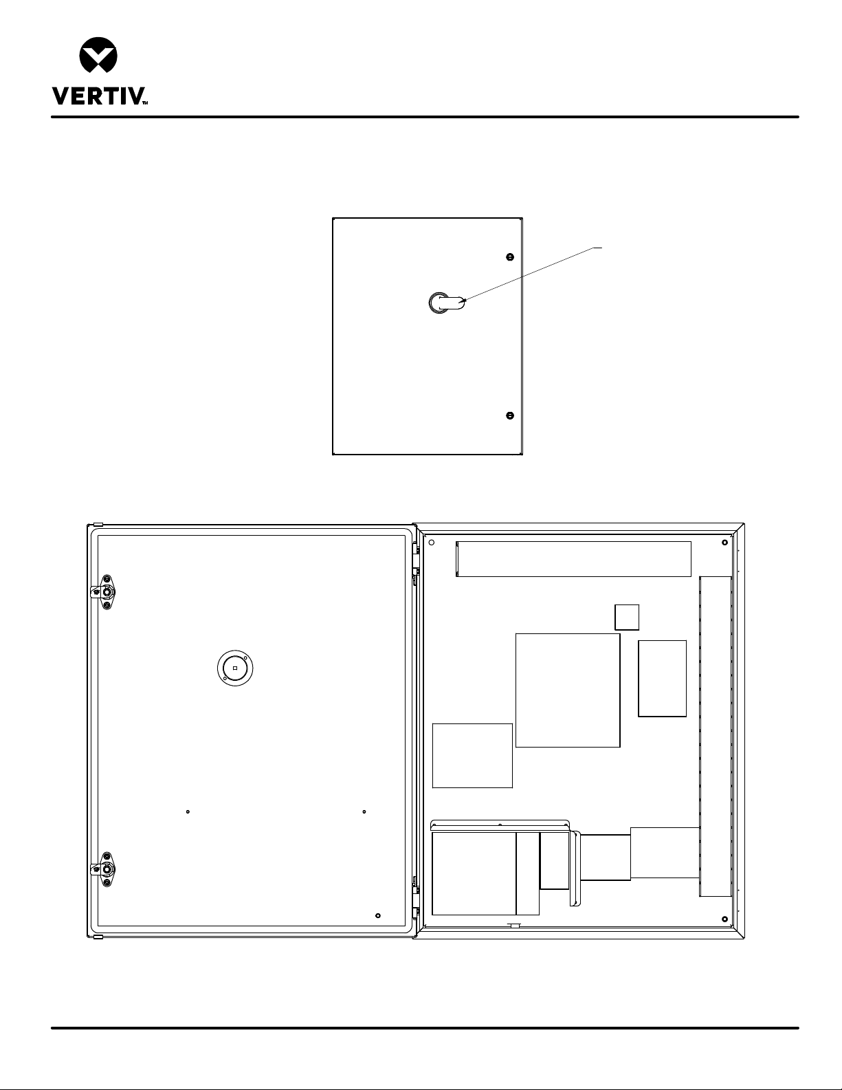
LIEBERT DSE
DP060 CUSTOMER CONNECTION ELECTRICAL PANEL
COMPONENT DEFINITIONS AND LOCATIONS
SINGLE POWER INPUT
DISCONNECT HANDLE
POWER METER
ASSEMBLY
(OPTIONAL)
LOW VOLTAGE TERMINALS
CUSTOMER CONNECTIONS
WIRE
DUCT
FUSED DISCONNECT
CONNECTORS
COMMUNICATION
ETHERNET SWITCH
FIVE PORT (OPTIONAL)
UNIT
TRANSFORMER
FUSES
208V, 230V, &
575V UNITS
GND
LUG
120V UTILITY
CIRCUIT
BREAKERS
AND
TERMINALS
(OPTIONAL)
POWER
DISTRIBUTION BLOCK
AND GND
DISTRIBUTION LUG
WIRE
DUCT
Form No.: DPN001040_REV4
DPN004591
Page :3 /5
REV : 1
REV DATE : 7/18
Page 84
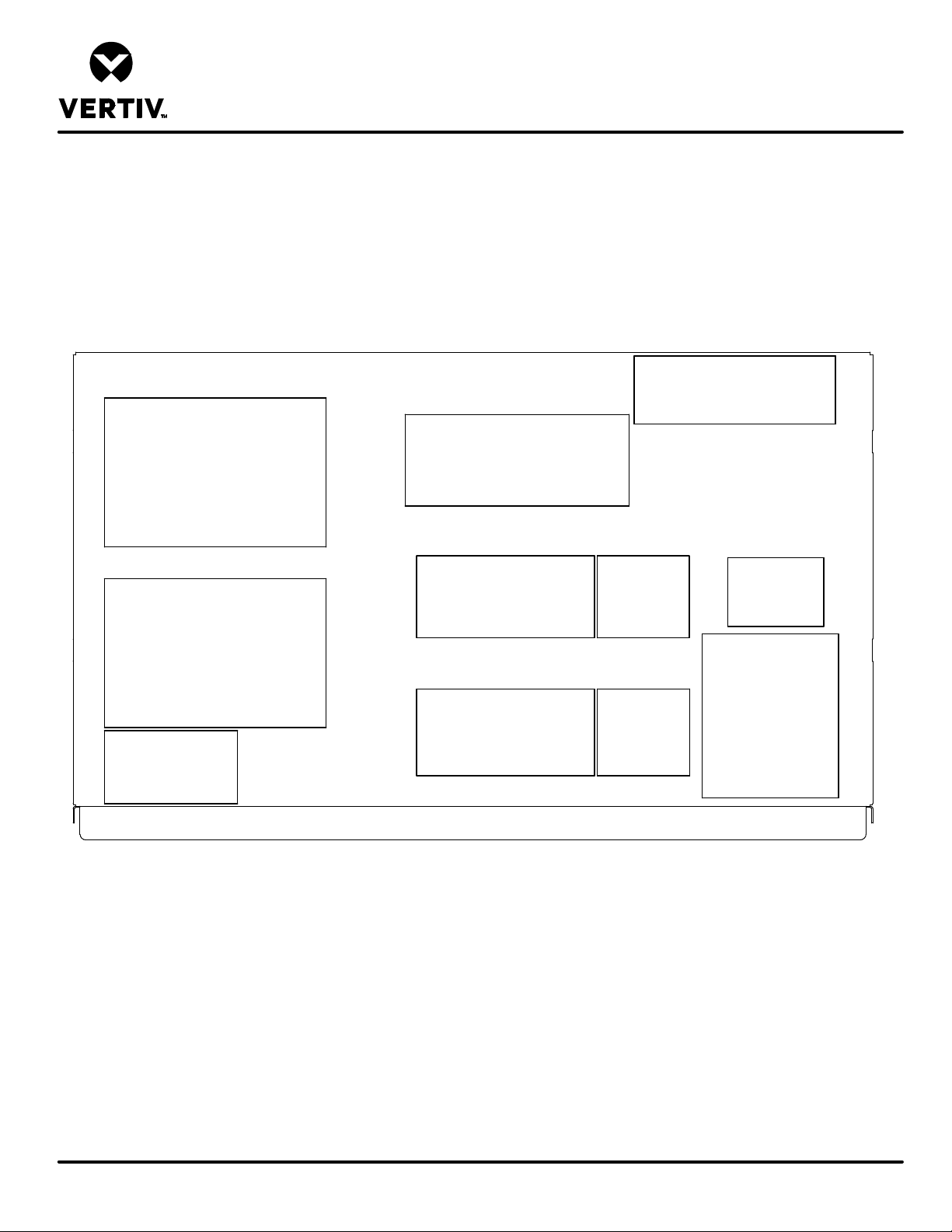
LIEBERT DSE
DP060 CONDENSER AND ECONOPHASE ELECTRICAL PANEL
COMPONENT DEFINITIONS AND LOCATIONS
24VAC TRANSFORMER
AND TERMINALS
ECONOPHASE
CONTROL
BOARD
CONDENSER
CONTROL
BOARD
LOW VOLT
TERMINALS
FACTORY USE
PUMP VFD
CONDENSER
FAN
FUSES
CONDENSER
FAN
CONTACTORS
PUMP
FUSES
PUMP
CONTACTOR
POWER
DISTRIBUTION
POWER
DISCONNECT
AND GND
LUGS
Form No.: DPN001040_REV4
DPN004591
Page :4 /5
REV : 1
REV DATE : 7/18
Page 85
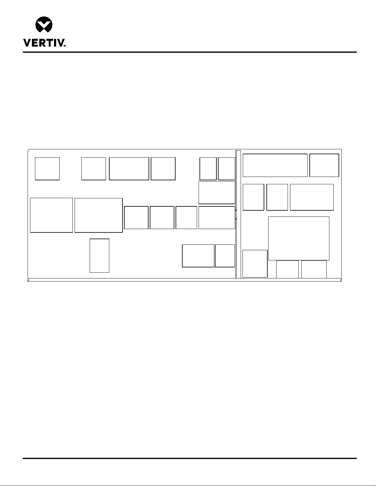
LIEBERT DSE
DP060 EVAPORATOR ELECTRICAL PANEL
COMPONENT DEFINITIONS AND LOCATIONS
POWER
BLOCK
FUSED DISCONNECT
AND GND LUG
CONDENSATE
PUMP
FUSES
(OPTIONAL)
24VDC POWER SUPPLY
AND BUFFER
GND
BAR
120V UTILITY
TRANSFORMER
FUSES
(OPTIONAL)
CRANKCASE
HEATER
FUSES
COMPRESSOR
FUSES
COMPRESSOR
CONTACTOR
FAN
CONTACTOR
COMPRESSOR
AND OPTION
FAN
FUSES
ISOLATION
TRANSFORMER
AND TRANSFORMER
TERMINALS
CONTROL
TRANSFORMER
RELAYS
CONTROL
FUSES
FAN
LOW
VOLT
TERMINALS
LOW VOLT TERMINALS
FACTORY USE ONLY
EXTRA
ALARM
RELAY
(OPTIONAL)
RELAYS
FOR
OPTIONS
FILTER
CLOG
CONTROL
SMOKE
DETECTOR
BOARD
(OPTIONAL)
INTELLISLOT AND
UNITIY CARDS
(OPTIONAL)
ICOM
BOARD
LOW VOLT
BOARD
24VDC BUFFER
RELAYS
(OPTIONAL)
FUSE
Form No.: DPN001040_REV4
DPN004591
Page :5 /5
REV : 1
REV DATE : 7/18
Page 86
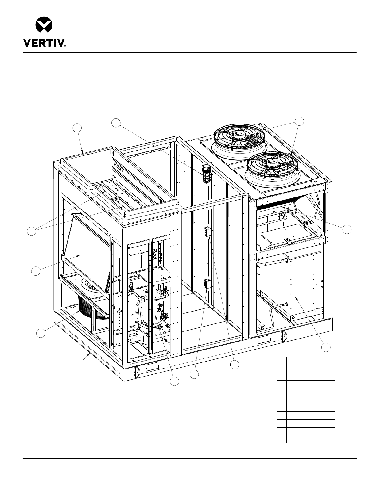
LIEBERT DSE
COMPONENT LOCATION DIAGRAM
EVAPORATOR COMPARTMENT DP060 TOP INLET/FRONT SUPPLY
8
4
7
2
10
11
Form No.: DPN001040_REV4
3
DPN004597
Page :1 /1
Front of unit
9
5
6
1
1 Compressor
2 Evaporator Coil
3 EC Fan
4 Interior 120V Light
5 Light Switch
6 GFI Outlet
7 Filters (qty. 3)
8 Duct Collar
9 Liebert EconoPhase
10 Condenser Fans
11 Condenser Coil
REV : 1
REV DATE : 7/18
Page 87
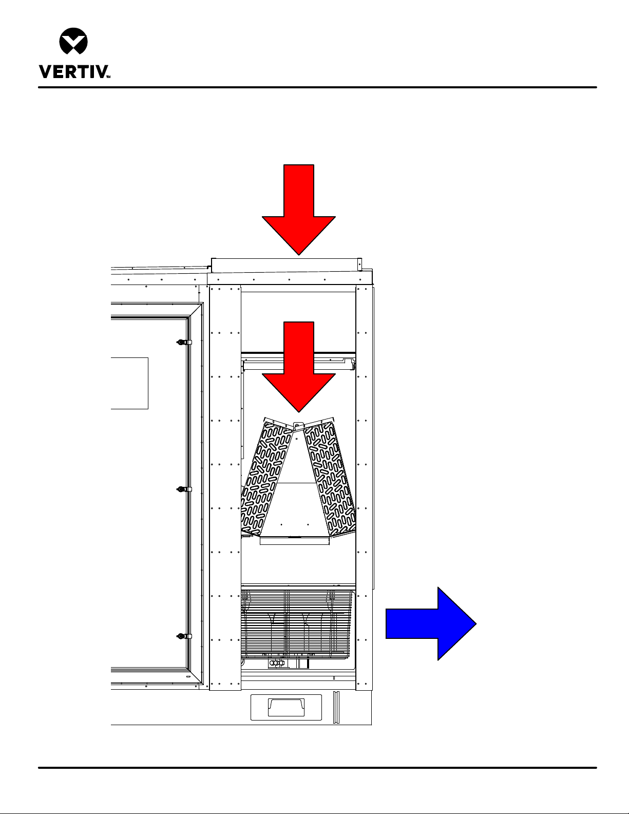
LIEBERT DSE
AIRFLOW SCHEMATIC
DP060 TOP INLET/FRONT SUPPLY
Return Air In
Some panels removed for clarity
Front of unit
Supply Air Out
Form No.: DPN001040_REV4
DPN004598
Page :1 /1
REV : 1
REV DATE : 9/18
Page 88
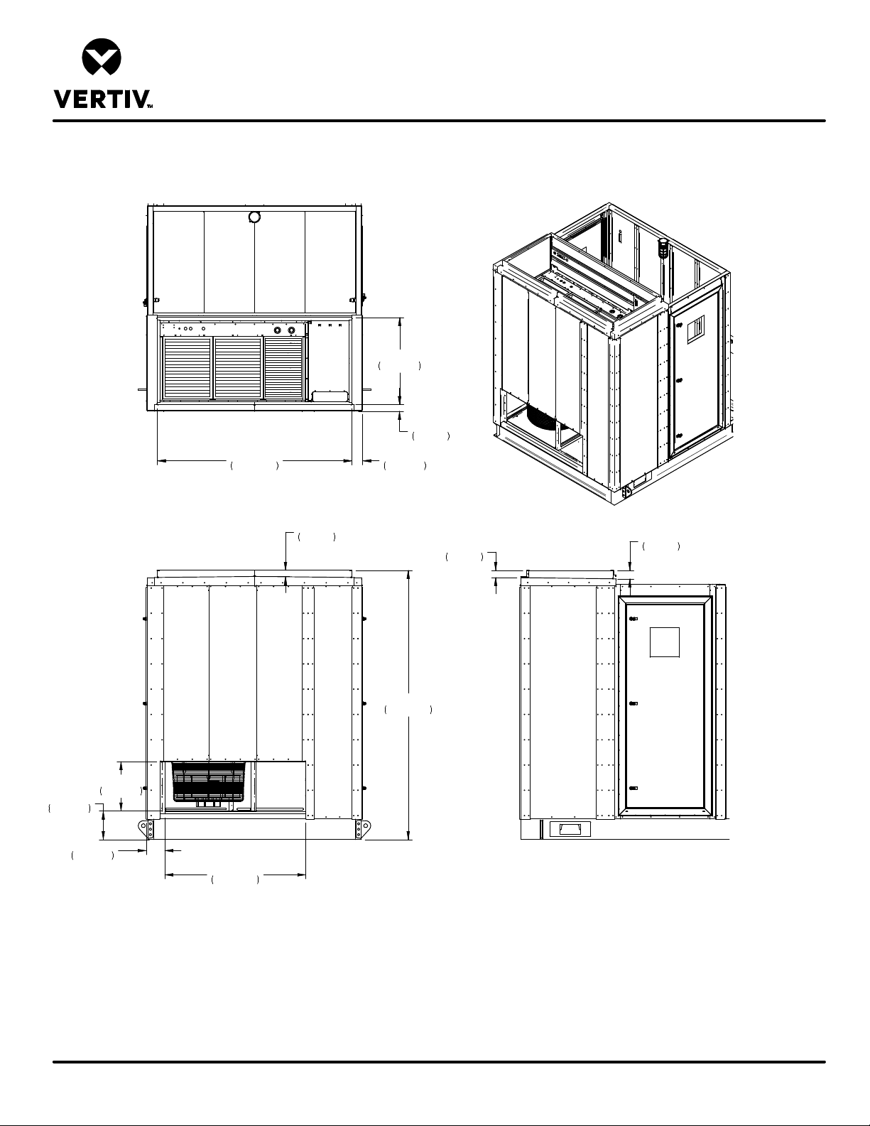
LIEBERT DSE
EVAPORATOR DUCTING DIMENSIONAL DATA
DP060 TOP INLET/FRONT SUPPLY
34"
864mm
2 5/8"
68mm
76 1/8"
1933mm
Top View
4 1/4"
107mm
11 1/8"
283mm
7 1/4"
184mm
19 3/8"
491mm
55 1/8"
1400mm
Front View
2 3/8"
60mm
At Center
of Duct Flange
105 1/4"
2673mm
2 7/8"
72mm
At Center
of Duct Flange
3 3/8"
84mm
At Rear of
Duct Flange
Right Side View
Form No.: DPN001040_REV4
Notes:
1. Seal all ducts.
DPN004599
Page :1 /1
REV : 1
REV DATE : 9/18
Page 89
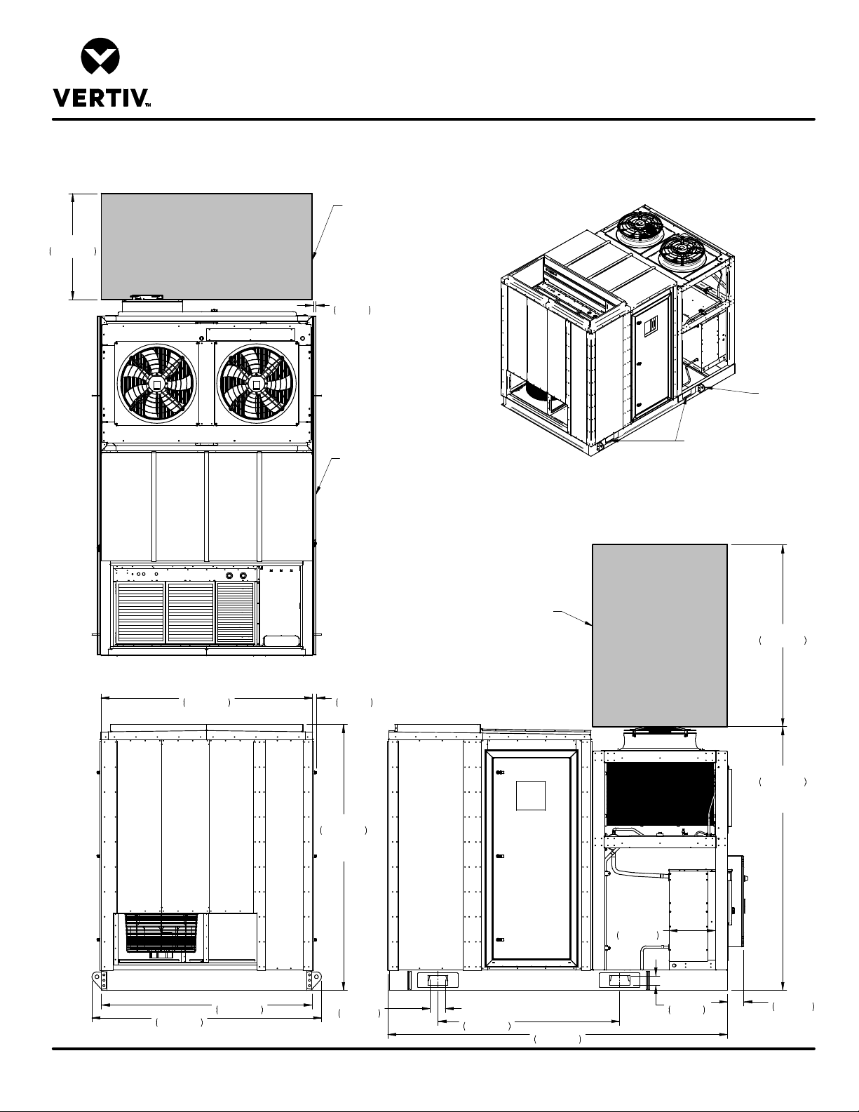
42"
1067mm
LIEBERT DSE
CABINET & ANCHOR DIMENSIONAL DATA
DP060 TOP INLET/FRONT SUPPLY
Shaded area indicates
required minimum clearance
for Electrical Box and
Component access.
1"
25mm
Typ. (2) Places
Shaded area indicates
recommended minimum
clearance between units
when lifting lugs are removed.
Removable
Lifting Lugs
(Typ. 4 Plcs.)
Forklift access
Typ. both sides
Form No.: DPN001040_REV4
DPN004600
Page :1 /2
Top View
83 3/4"
2127mm
91"
2310mm
Front View
83 1/2"
2121mm
1 5/8"
41mm
Typ.
105 1/4"
2673mm
Overall
Height
5 7/8"
150mm
Typ. (4) Plcs.
Shaded area indicates
recommended minimum
vertical clearance above fans.
Right Side View
72"
1829mm
134 1/2"
3418mm
18 1/2"
468mm
3 3/4"
96mm
Typ. (4) Plcs.
72"
1829mm
104 1/2"
2653mm
Height from top of fans
to bottom of unit
6 1/2"
164mm
REV : 3
REV DATE : 2/19
Page 90
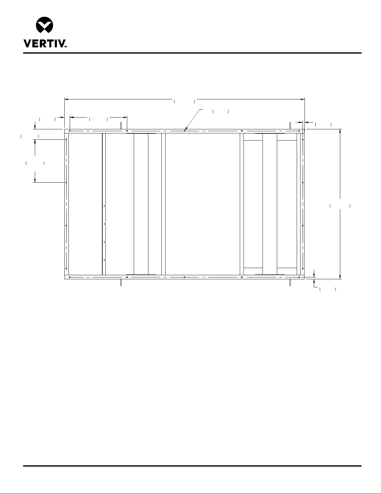
5 3/4"
146mm
24"
610mm
Typ.
3"
76mm
Typ.
Typ.
LIEBERT DSE
CABINET & ANCHOR DIMENSIONAL DATA
DP060 TOP INLET/FRONT SUPPLY
134"
32"
813mm
Typ.
3404mm
5/8"
O
16mm
Anchor Holes
Typ. (18) Plcs.
1"
25mm
Rear
of
Unit
Bottom View
Front
of
Unit
1"
25mm
83 1/2"
2121mm
Form No.: DPN001040_REV4
Notes:
1. Underside of base of unit. Components removed for clarity.
2. Mounting requirement details such as brand type, embedment depth, edge spacing, anchor spacing, concrete strength, wall bracing, and special inspection
must be outlined and approved by the project Structural Engineer of Record.
DPN004600
Page :2 /2
REV : 3
REV DATE : 2/19
Page 91
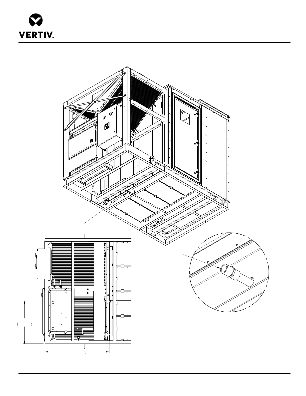
LIEBERT DSE
CONDENSATE DRAIN ACCESS & LOCATION
DP060 PERIMETER UNIT
Form No.: DPN001040_REV4
Condensate Drain Location
Rear
of
Unit
33 3/4"
857mm
51"
1294mm
Bottom View
showing Condensate Drain locating dimensions
DPN004601
Page :1 /1
A
3/4” NPT female fitting
for Condensate Drain
DETAIL A
Condensate Drain Location
REV : 1
REV DATE : 7/18
Page 92
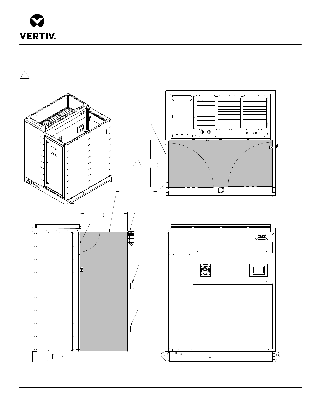
LIEBERT DSE
EVAPORATOR COMPARTMENT SERVICE AREA
Notes:
1. Evaporator Coil is removed into service area and through either door.
Requires 36" (914mm) X 60" (1524mm) clearance outside of door area.
2. NOTICE: Risk of equipment damage. Evaporator accent panel cannot be opened
while exterior man door is closed.
DP060 TOP INLET/FRONT SUPPLY
Access Door
swings inward
as shown
(Typ. both sides)
36"
1
914mm
Shaded are indicates
minimum clearance
required in front of
Liebert DSE unit.
36"
914mm
Filter
Access
120V
Interior
Light
Top View of Evaporator Section
Form No.: DPN001040_REV4
Side View of Evaporator Compartment
Access Door removed for clarity
DPN004602
Page :1 /1
120V Interior
Light Switch
GFCI Outlet
Front View of Evaporator Unit
Wall & Access Doors removed for clarity
REV : 2
REV DATE : 9/18
Page 93

LIEBERT DSE
Wire range and tightening torque will vary based on
On any alarm, normally open dry contact is closed across terminals 75 & 76 for remote indication. 1 AMP, 24VAC
Terminals for the connection of a field supplied 120V 20A utility power to feed the light and
alarm, two additional normally open contacts are closed across terminals 94 & 95 and 96 & 97 for
dry contact is closed across terminals 84 & 85
ELECTRICAL FIELD CONNECTIONS
DP060 UNIT DEFINITIONS AND LOCATIONS
SINGLE POWER INPUT
STANDARD ELECTRICAL CONNECTIONS
1) HIGH VOLTAGE ENTRANCE – This area will be used for the high voltage fittings. Enclosure is not provided with holes or knockouts,
which must be done by the installer in the field. The fittings used must have the proper environmental rating per code.
2) LOW VOLTAGE ENTRANCE – This area will be used for the low voltage and communication fittings. Enclosure is not provided with
holes or knockouts, which must be done by the installer in the field. The fittings used must have the proper environmental rating per
code.
3) HIGH VOLTAGE WIRE DUCT – Wire duct to be used by the installer for high voltage wire routing.
4) MAIN UNIT POWER CONNECTIONS – Terminals are located on top of the locking disconnect switch. See side of disconnect switch
for wire range and tightening torque. Three phase service not provided by Liebert.
disconnect size. Refer to label on side of disconnect.
5) EARTH GROUND CONNECTION FOR MAIN UNIT POWER – Terminal for field supplied Source 1 earth grounding wire. Earth
grounding required for Liebert units. 14-2AWG wire range, 275 in-lb wire tightening torque.
6) REMOTE SHUTDOWN - Replace existing jumper between terminals 37 & 38 with field supplied normally closed switch having a
minimum 75VA, 24VAC rating. Use field supplied Class 1 wiring.
7) CUSTOMER ALARM INPUTS – Terminals for field supplied, normally open contacts, having a minimum 75va, 24vac rating, between
terminals 24 & 50, 51, 56. Use field supplied Class 1 wiring. Terminal availability varies by unit options.
8) COMMON ALARM –
max load. Use Class 1 field supplied wiring.
9) REMOTE HUMIDIFIER – On any call for humidification, normally open dry contact is closed across terminals 11 & 12 to signal field
supplied remote humidifier. 1 AMP, 24VAC max load. Use Class 1 field supplied wiring.
10) FIELD SUPPLIED 120V UTILITY POWER –
service electrical outlet. 22-8AWG wire range, 14.2lb-in tightening torque.
11) EARTH GROUNDING CONNECTION FOR FIELD SUPPLIED 120V UTILITY POWER - Terminal for field supplied 120V earth
grounding wire. Earth grounding required for Liebert units. 14-2AWG wire range, 275 in-lb wire tightening torque.
LOW VOLTAGE TERMINAL CONNECTIONS
12) EXTRA REMOTE UNIT SHUTDOWN – Two additional contact pairs available for unit shutdown (labeled as 37B & 38B, 37C & 38C).
Replace jumpers with field supplied normally closed switch having a minimum 75VA, 24VAC rating. Use field supplied Class 1 wiring.
13) EXTRA COMMON ALARM – On any
remote indication. 1 AMP, 24VAC max load. Use Class 1 field supplied wiring.
14) MAIN FAN AUXILIARY SWITCH – On closure of the main fan contactor, normally open
for remote indication. 1 AMP, 24VAC max load. Use Class 1 field supplied wiring.
15) LIQUITECT SHUTDOWN AND DRY CONTACT – On LiquiTect activation, normally open dry contact is closed across terminals 58 &
59 for remote indication (LiquiTect sensor ordered separately). 1 AMP, 24VAC max load. Use Class 1 field supplied wiring.
NOTE: All low voltage terminal connections are spring-cage with a wire range of 28-12AWG.
NOTE: Items 10 and 11 are not present when the Unit supplied 120V utility option is selected.
DPN004732
Page :1 /3
Form No.: DPN001040_REV4
REV : 1
REV DATE : 1/19
Page 94

LIEBERT DSE
Use shielded
Refer to specification sheet for
total unit full load amps, wire size amps, and max overcurrent protection device size.
ELECTRICAL FIELD CONNECTIONS
DP060 UNIT DEFINITIONS AND LOCATIONS
SINGLE POWER INPUT
STANDARD COMMUNICATION CONNECTIONS
16) RS485 BMS CONNECTION – Terminal TB3-1 is TX/RX+. Terminal TB3-2 is TX/RX-. Terminal TB3-3 is earth ground.
cable with 120ohm characteristic impedance. (Supplied by other).
17) CANBUS REMOTE SENSOR CONNECTION(P67) – Remove the inserted plug from this connector and attach the remote sensor
cable to power and communicate with Liebert remote Temperature/humidity sensors. Use shielded cable with 120ohm characteristic
impedance. (Supplied by other).
18) ETHERNET BMS CONNECTION(P74) – RJ-45 connection for connecting to BMS Ethernet network. Use Class 5 shielded cable
(Supplied by other).
19) ETHERNET UNIT TO UNIT CONNECTION(P64) – RJ-45 connection for connecting to other units. Use Class 5 shielded cable
(Supplied by other).
NOTE: All low voltage terminal connections are spring-cage with a wire range of 28-12AWG.
NOTE: All communication cables should be separated from high-voltage wiring.
OPTIONAL ELECTRICAL CONNECTIONS
20) SMOKE SENSOR ALARM – Factory wired dry contacts from smoke sensor are 91-common, 92-Normally Open, and 93-Normally
Closed. Supervised contacts, 80 & 81, open on sensor trouble indication. This smoke sensor is not intended to function as, or
replace, any room smoke detection system that may be required by local or national codes. 1 AMP, 24VAC max load. Use Class 1
field supplied wiring.
21) CONDENSATE ALARM – Terminals are present with condensate pump option. On pump high water indication, normally open dry
contact is closed across terminals 88 & 89 for remote indication. 1 AMP, 24VAC max load. Use Class 1 field supplied wiring.
NOTE: All low voltage terminal connections are spring-cage with a wire range of 28-12AWG.
NOTE: Terminals for item 20 and 21 are always present. Refer to the order to verify if the options are present.
DPN004732
Page :2 /3
Form No.: DPN001040_REV4
REV : 1
REV DATE : 1/19
Page 95
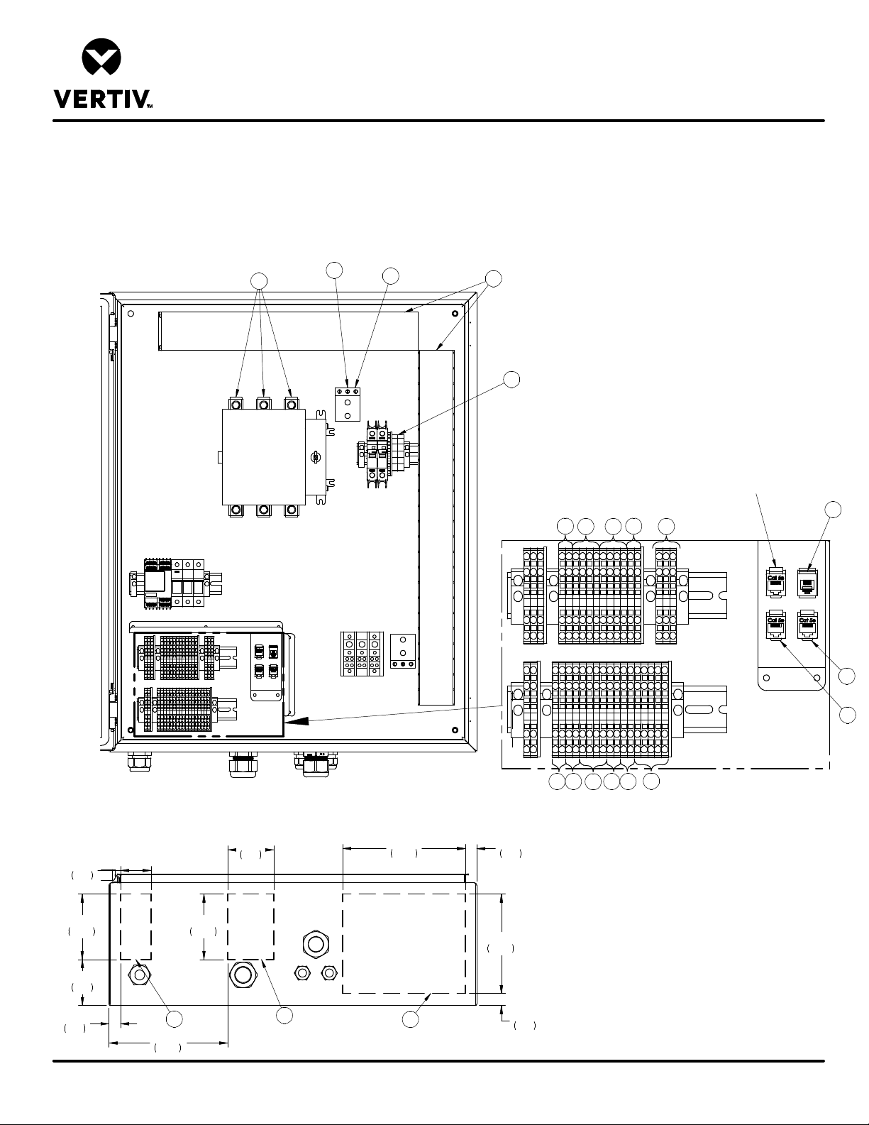
LIEBERT DSE
ELECTRICAL FIELD CONNECTIONS
DP060 UNIT DEFINITIONS AND LOCATIONS
SINGLE POWER INPUT
4
5
11
3
10
FACTORY USE ONLY
17
6 9
12 7 16
19
Form No.: DPN001040_REV4
2"
51
4 1/4"
109
3"
76
3/4"
19
DPN004732
Page :3 /3
200A DISCONNECT VIEW
3"
76
FRONT
4 1/4"
109
2
7 3/4"
197
2
BOTTOM VIEW
8"
203
1
BACK
3/4"
19
6 1/2"
165
3/4"
20
15 8
18
20
14 21
13
REV : 1
REV DATE : 1/19
Page 96
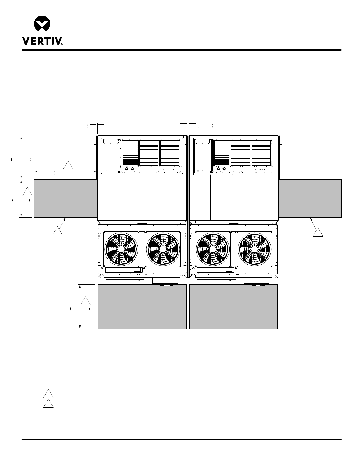
LIEBERT DSE
INSTALLATION & SERVICE CLEARANCE DATA
DP060
41 1/8"
1044mm
36"
914mm
Typ.
1"
25mm
Typ.
1
60"
1524mm
1
2
2"
51mm
Between Units
2
Form No.: DPN001040_REV4
DPN004756
Page :1 /1
1
42"
1067mm
Typ.
Top View
Rear of Units
Notes:
1. Required clearance between the end unit and the nearest obstruction.
2. Evaporator Coil may be removed into service area and through either door.
3. See DPN004600 fo additional dimensional information.
4. Multiple units can be placed side by side. Two units shown for reference.
REV : 0
REV DATE : 5/18
Page 97

Vertiv | Liebert® DSE060™ Installer/User G uide
Page 98

VertivCo.com | Vertiv Headquarters, 1050 Dearborn Drive, Columbus, OH, 43085, USA
© 2018 VertivCo. Allrights reserved. Vertiv and the Vertivlogo are trademarks or registered trademarks of Vertiv Co. Allother names and logos referred to
are trade names, trademarks or registered trademarks of their respective owners. While every precaution has been taken to ensure acc uracy and
completeness herein, Vertiv Co. assumes no responsibility, and disclaims all liability, for damages resulting from use of this information or for anyerrors or
omissions. Specifications are subject to change without notice.
SL-18955_REV1/590-1836-501B
 Loading...