

Page 1

Liebert DM S
eries
Precision Air Conditioner
User Manual
Page 2

Page 3

Copyright by Vertiv Co. Ltd.
The content in this document is subject to change without notice. All rights, including rights of
translation, reproduced by printing, copying or similar methods, and even of parts, are reserved.
Violators will be liable for damages. All rights, including rights deriving from patent license or
registration of a utility model or design, are reserved. No part of this document may be
reproduced or transmitted in any form or by any means without the prior written consent of
Vertiv Co. Ltd.
Notice
The purchased products, services, and features are stipulated by the contract made between
Vertiv Co., and the customer. All or part of the products, services, and features described in this
document may not be within the purchasing scope or the usage scope. Unless otherwise
specified in the contract, all statements, information, and recommendations in this document are
provided "AS IS" without warranties, guarantees or representations of any kind, either express or
implied. The information in this document is subject to change without notice. Every effort has
been made in the preparation of this document to ensure the accuracy of the contents, but all
statements, information, and recommendations in this document do not constitute a warranty of
any kind, express or implied.
Vertiv Co., Ltd.
• China
Website: www.vertivco.com.
E-mail:
Customer service hotline:
• Asia Pacific
Homepage: www.vertivco.com.
E-mail:
For Technical Support, users may contact the nearest Vertiv Co. local sales office or service
center.
4008876510
Vertiv | Liebert DM Series Precision Air Conditioner | User Manual
Page 4
Purpose of the Document
Situation
Description
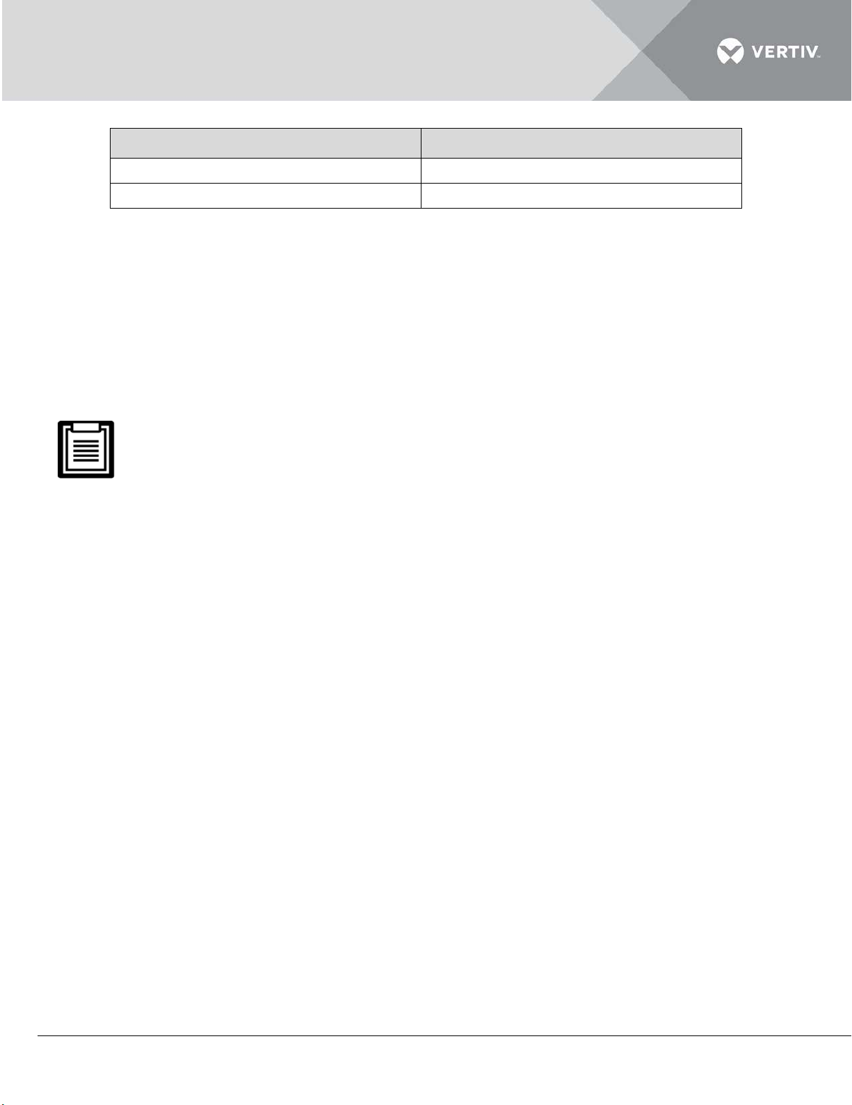
The Warning/Danger/Caution note
degradation, or interruption in service.
The Note section indicates additional and
This document applies to the Liebert DM series of precision air conditioners and cooling solutions
which maintain an optimal environmental control mainly for testing laboratories, data center rooms
and similar technological ecosystems at minimal operating costs.
This document explains the product description, installation measures, operational workflow,
maintenance, and detailed aspects from the user perspective. The figures used in this document
are for reference only.
Please read this manual carefully before installing, maintaining, and troubleshooting, especially
the warning information in the manual
Styling used in this Guide
The styles used in the manual will be defined as mentioned in the following table:
indicates a hazardous or potentially
Warning/Danger/Caution
harmful situation that can result in death
or injury. It also indicates instructions that
need to be adhered to, failing which may
result in danger and safety issues thereby
having an adverse effect on the reliability
of the device and security. Even for
practices not related to physical injury, the
content under the Warning heading is
used for precautions which need to be
taken which, otherwise, could result in
equipment damage, performance
Note
Vertiv | Liebert DM Series Precision Air Conditioner | User Manual
useful information including tips and
tweaks. It also calls attention to best
practices and industry-best protocols that
are standardized and help make maximum
utilization of the resources at hand.
Helpful information related to the
mainstream stuff also comes under the
Note heading helping the users get to
grips with the definitions, concepts, and
terminologies used in the manual.
Page 5
Version History
Issue
Revision
Changes
1
1.0
-------
afety Precautions and Measures
S
The important safety precautions and measures that should be followed during the installation and
maintenance of the Liebert DM models are described in the following sections.
Read the manual prior to installation and operation of the unit. Only qualified personnel should
move, install, or service this equipment.
The user reads and takes into account all the precautions, compliance, and safety measures before
working on the equipment. The unit control must be used exclusively for the purpose which it is
intended for; the manufacturer takes no liability for incorrect use or a modification to the unit
control.
Adhere to all the Warnings and Cautionary measures included in the manual.
Please read this manual carefully before installing, maintaining and troubleshooting; especially the
Warning/ Danger/ Caution information in the User Guide. Apart from the User Guide, also pay
attention to the warning labels on the unit and its components.
This manual is retained for the entire service life of the machine. The user must read all the
precautions, danger, warnings, and cautionary measures mentioned in the manual prior to
carrying out any operations on the machine. Each machine is equipped with an electric
insulation which allows the users to work in safe conditions. The main switch is positioned on
the electrical panel cover; Open the right door to access it. Before any maintenance operation,
switch off the machine with this electronic insulation device in order to eliminate risks such as
electrical shocks, burns, automatic restarting, moving parts, and remote control. The panel key,
supplied along with the unit, must be kept by the personnel responsible for the maintenance.
The protective covers can be removed after the electric power has been cut off by opening
the main switch.
In the following section, take a look at the various cautionary measures and warnings that need to be read
carefully prior to installing or operating the system.
Disconnect the local and remote power supplies prior to working with the unit.
Prior to the installation process, read all the instructions, verify if all the parts are in place, and check the
nameplate to ensure that the voltage matches the utility power that is available for that unit.
Vertiv | Liebert DM Series Precision Air Conditioner | User Manual
Page 6

The controller doesn’t isolate power from the unit even in the Off mode. Moreover, some internal
components require and receive power even during the Off mode.
If the unit door is open while the fans are operating, the airflow may result in abrupt slamming of the door
resulting in injury. Another aspect is the presence of small objects in the fans bay which may result in object
ejection during the fan start-up and there is a probable risk of being hit by these objects leading to grievous
injury as well as causing equipment damage.
The unit contains fluids and gasses under high pressure. Therefore, the pressure should be relieved
before working with the piping.
Various components such as compressors, refrigerant discharge lines, and humidifiers are extremely hot
during the unit operation. Therefore, allow sufficient time for the unit to cool down before working with the
unit cabinet. Handle the unit with extreme caution and wear safety equipment such as protective gloves,
safety shoes, and arm protection while working with the hot compressors, discharge lines, and reheats.
There is a risk of leaking water that can cause damage to the equipment as well as the building. There
should be an effective water drain connection and facilities. Installation should be precise. Implementation
of the application and service practices should be suitable and fault-free. Not complying with these norms
will result in water leakage from the unit. Water leakage can result in massive damage and loss of critical
equipment in the hosting ecosystem. Therefore, care should be taken to ensure that the unit must not be
located directly above any equipment that could sustain damage due to water and excessive moisture.
Using a leak detection system for unit and system supply lines are recommended by Vertiv Co.
Vertiv | Liebert DM Series Precision Air Conditioner | User Manual
Page 7

TABLE OF CONTENTS
PART I - GENERAL INFORMATION
1 Introduction ......................................................................................................................................................................................... 2
1.1 Model Nomenclature....................................................................................................................................................... 3
1.2 Basic Performance Parameters .............................................................................................................................. 3
1.3 Product Description ........................................................................................................................................................ 4
1.3.1 Compressor ......................................................................................................................................................... 5
1.3.2 Evaporator ........................................................................................................................................................... 6
1.3.3 Thermal expansion valve (TXV) ......................................................................................................... 6
1.3.4 Micro-processing Controller.................................................................................................................. 7
1.3.5 Strainer .................................................................................................................................................................. 7
1.3.6 Filter ......................................................................................................................................................................... 8
1.3.7 Centrifugal Fan................................................................................................................................................. 8
1.3.8 Condenser ........................................................................................................................................................... 8
1.3.9 Sight Glass .......................................................................................................................................................... 9
1.3.10 Infrared Humidifier ..................................................................................................................................... 9
1.4 Optional Components ................................................................................................................................................ 10
1.4.1 Electric Heater ............................................................................................................................................. 10
1.4.2 Remote Monitor ........................................................................................................................................... 10
1.4.3 Energy-Saving Card ...................................................................................................................................11
1.4.4 Power SPD..........................................................................................................................................................11
1.5 Working Conditions................................................................................................................................... 11
1.5.1 Operating Environment ............................................................................................................................ 12
1.5.2 Storage Environment ................................................................................................................................ 13
Vertiv | Liebert DM Series Precision Air Conditioner | User Manual
Page 8

1.5.3 Refrigerant Charging Requirement ................................................................................................ 13
PART II - INSTALLATION
2 Installation .......................................................................................................................................................................................... 15
2.1 Pre-Installation ................................................................................................................................................................. 15
2.1.1 Transportation and Movement ........................................................................................................... 15
2.1.2 Unpacking..........................................................................................................................................................16
2.1.3 Inspection .......................................................................................................................................................... 17
2.2 Installation Preparation (Site Preparation) ................................................................................................. 17
2.2.1 Equipment Room Requirement.......................................................................................................... 17
2.2.2 Installation Space requirements .......................................................................................................18
2.2.3 Installation Tools.........................................................................................................................................20
2.3 Mechanical Installation .............................................................................................................................................. 21
2.3.1 System arrangement during installation..................................................................................... 21
2.3.2 System Installation Mode ..................................................................................................................... 23
2.3.3 Product Dimensions ................................................................................................................................. 24
2.3.4 Outdoor unit ................................................................................................................................................... 25
2.3.5 Indoor Unit Installation ........................................................................................................................... 26
2.3.6 Outdoor Unit Installation ...................................................................................................................... 27
2.3.7 Procedure ......................................................................................................................................................... 27
2.3.8 Piping for AC Unit ...................................................................................................................................... 29
2.3.9 Installation Notes Of Connector ..................................................................................................... 30
2.3.10 Required Pipe Connections............................................................................................................... 31
2.3.11 Connecting Refrigerant Pipe ............................................................................................................. 31
2.3.12 Pipe connector position ...................................................................................................................... 33
2.3.13 Connecting discharge pipe ............................................................................................................... 34
Vertiv | Liebert DM Series Precision Air Conditioner | User Manual
Page 9

2.3.14 Connecting liquid pipe ......................................................................................................................... 34
2.3.15 Connecting Drain Pipe Of Indoor Unit ...................................................................................... 35
2.3.16 Connecting Humidifier Water Supply Pipe (If Applicable) ........................................ 35
2.3.17 Removing Transportation Fastener And Vibration Absorber ................................. 35
2.3.18 Adding Refrigerant For Long Pipe System ........................................................................... 36
2.3.19 Check List ...................................................................................................................................................... 37
2.4 Electrical Installation .................................................................................................................................................. 38
2.4.1 On-site Wire connections ..................................................................................................................... 38
2.4.2 Installation Notes ....................................................................................................................................... 38
2.4.3 Connecting Power Cable Of Indoor Unit ................................................................................... 39
2.4.4 Connecting Power Cable Of Outdoor Unit ............................................................................. 40
2.4.5 Connecting Control Terminals ......................................................................................................... 41
2.4.6 Connecting Monitoring Port Cable ............................................................................................... 45
2.4.7 Connecting Energy-Saving Card .................................................................................................... 45
2.4.8 Checklist ........................................................................................................................................................... 47
PART III - SYSTEM OPERATION & GENERAL MAINTENANCE
3 System Operation ......................................................................................................................................................................... 51
3.1 Start-Up Inspection ....................................................................................................................................................... 51
3.2 Micro-Processing Controller................................................................................................................................. 52
3.2.1 Features ............................................................................................................................................................. 52
3.2.2 Appearance ..................................................................................................................................................... 52
3.2.3 LCD Screen ..................................................................................................................................................... 53
3.2.4 Control Buttons ........................................................................................................................................... 53
3.2.5 Control Buttons Operation Example ............................................................................................ 54
Vertiv | Liebert DM Series Precision Air Conditioner | User Manual
Page 10

3.2.6 ON Screen ........................................................................................................................................................ 55
3.2.7 Language Screen ........................................................................................................................................ 55
3.2.8 Normal Screen .............................................................................................................................................. 56
3.2.9 Password Screen ........................................................................................................................................ 56
3.3 Function Testing ........................................................................................................................................................... 57
3.3.1 Cooling ................................................................................................................................................................ 57
3.3.2 Heating............................................................................................................................................................... 58
3.3.3 Humidifying .................................................................................................................................................... 58
3.3.4 Dehumidifying .............................................................................................................................................. 58
3.3.5 Checking Refrigerant Charge Capacity of Low-Temp Outdoor .............................. 58
3.4 Micro-Processing Controller Menu Options ............................................................................................. 59
3.4.1 Main Menu........................................................................................................................................................ 59
3.4.2 Alarm Menu ................................................................................................................................................... 60
3.4.3 Set Points ......................................................................................................................................................... 63
3.4.4 System Status............................................................................................................................................... 63
3.4.5 System Menu .................................................................................................................................................66
3.4.6 Help Menu ....................................................................................................................................................... 67
3.4.7 Display Set .......................................................................................................................................................68
4 General Maintenance ................................................................................................................................................................69
4.1 Electric Inspection ........................................................................................................................................................ 70
4.2 Indoor Unit Maintenance ........................................................................................................................................ 70
4.2.1 Filter ...................................................................................................................................................................... 70
4.2.2 Fan ......................................................................................................................................................................... 72
4.2.3 Drain Pipe......................................................................................................................................................... 72
4.2.4 Heater ................................................................................................................................................................. 72
Vertiv | Liebert DM Series Precision Air Conditioner | User Manual
Page 11

4.2.5 Humidifier ........................................................................................................................................................ 72
4.2.6 Power SPD ....................................................................................................................................................... 74
4.2.7 Thermal Expansion Valve..................................................................................................................... 76
4.2.8 High-Pressure Switch And Low-Pressure Switch ............................................................. 76
4.2.9 Compressor .................................................................................................................................................... 77
4.3 Outdoor Unit Maintenance .................................................................................................................................... 78
4.3.1 Refrigeration System................................................................................................................................ 78
4.3.2 Air-Cooled Condenser ............................................................................................................................ 78
4.3.3 Low-Temperature Unit Of Low-Temp Outdoor Unit ....................................................... 78
4.4 Maintenance Inspection Checklist .................................................................................................................. 79
4.5 Troubleshooting .............................................................................................................................................................81
APPENDIX 1 - Crcuit Diagrams .................................................................................................................................... 86
APPENDIX 2 Menu Structure ...................................................................................................................................... 87
APPENDIX 3 Parameter Setting Table................................................................................................................... 88
APPENDIX 4 - RDU-Cooling AC Single-Unit Manager Software Introduction ............................91
APPENDIX 5 - Hazardous Substances List........................................................................................................94
Vertiv | Liebert DM Series Precision Air Conditioner | User Manual
Page 12

PART I
GENERAL INFORMATION
Vertiv | Liebert DM Series Precision Air Conditioner | User Manual 1
Page 13

1 Introduction
The Liebert DM series is the next generation series of small air conditioners that provide precise
environmental control. The Liebert DM models are the latest in the long line of modern enterprisegrade products from the Liebert family. Incorporating the high standards associated with the Liebert
name, the DM series utilizes the latest technology, system components, and a streamlined
manufacturing process.
Liebert DM air conditioners are products that are specifically created and designed for cooling the
electrical devices. It is applicable to equipment rooms, computer rooms, and similar ecosystems
which call for a high degree of accuracy and precision in maintaining the ambient temperature. It
addresses the needs and challenges associated with such applications and setups. It caters to
sensitive applications which need a suitable environment for optimal performance. Therefore, care
should be taken while testing these sensitive products or maintaining a favorable environment for
mission critical equipment, as even a slight deviation may lead to inaccurate results. Precision Air
Conditioning must not only keep room conditions within a specific range but also must have the
precision to react quickly to a drastic change in heat load and prevent wide temperature fluctuations.
The DM air cooled AC unit is packed with features such as high reliability, high sensible heat ratio,
and large airflow. The unit is an air-cooled single cooling system and configured with DC Speed
Regulation back- inclined centrifugal fan.
Packed with a host of features, it lowers the sound emissions significantly and thereby reduces the
noise pollution. It is a top-notch system that adheres to the standard in Precision Air Cooling in
terms of energy-efficiency, space requirements, and reliability.
Vertiv | Liebert DM Series Precision Air Conditioner | User Manual 2
Page 14
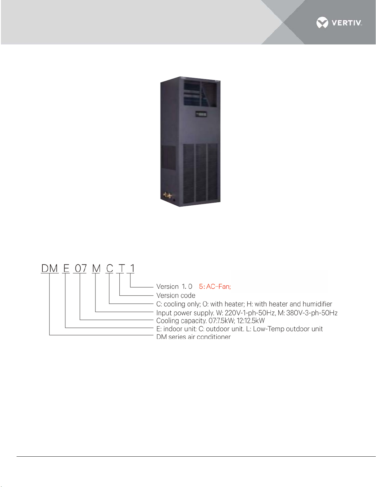
Figure 1-1 shows the appearance of various models in the Liebert DM series:
Figure 1-1
1.1 Model Nomenclature
The model nomenclature of the Liebert DM AC is shown in Figure 1-2:
Figure 1-1
1.2 Basic Performance Parameters
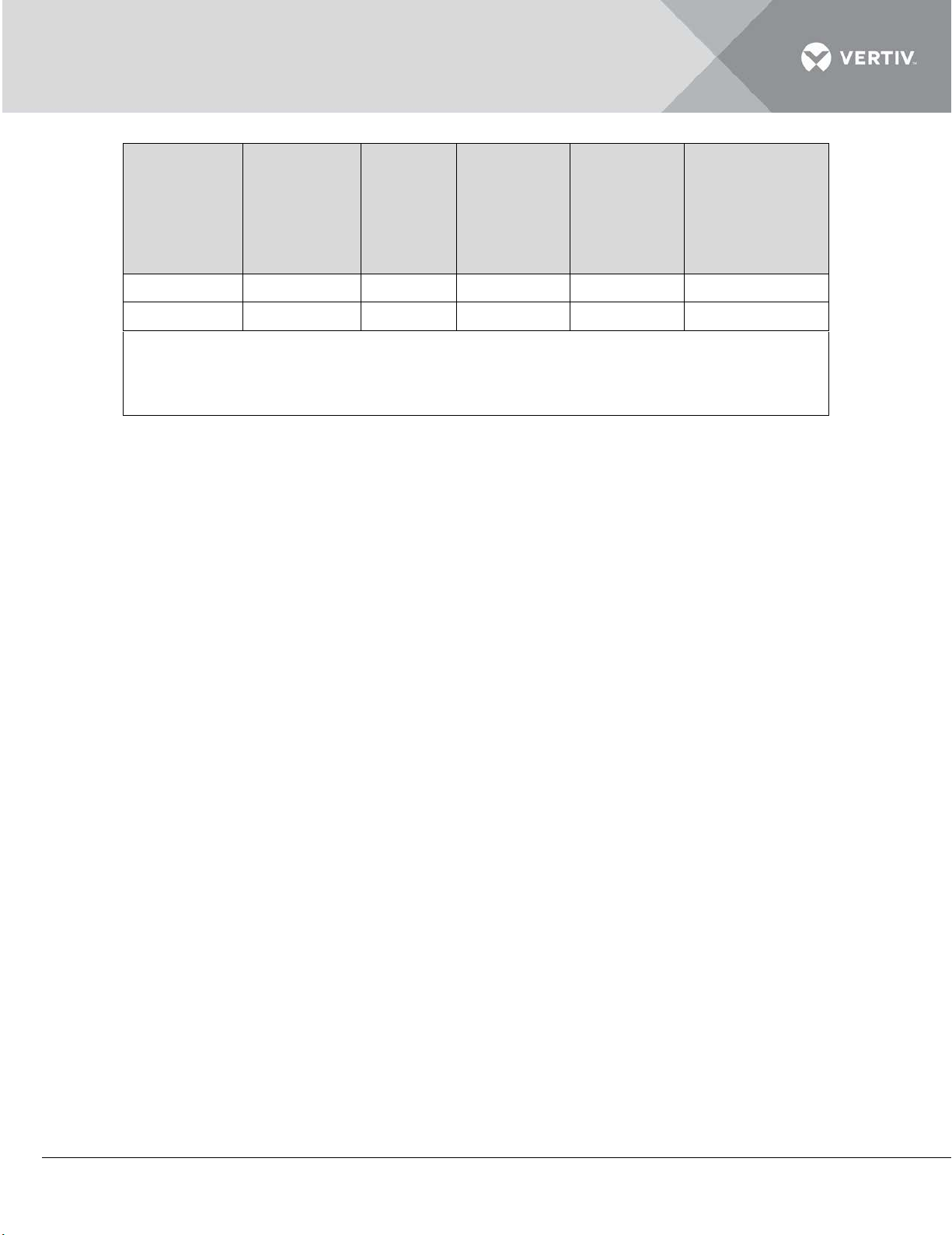
The basic performance parameters of the Liebert DM AC are given in Table within
Listing 1.1.
Listing 1.1
Vertiv | Liebert DM Series Precision Air Conditioner | User Manual 3
Page 15
Model
Nominal
cooling
capacity
(kW)
Power
(kW)
Annual
energy
efficiency
ratio
Heating
capacity
[1]
(kW)
Humidification
capacity
[2]
(kg/h)
DME07M**5
6.85
2.36
2.9
3.2
1.5
DME12M**5
11.9
4.1
2.9
3.2
1.5
Note:
[1]: The heating capacity is only for the models with heating function;
[2]: The humidification capacity is only for the models with humidification function
1.3 Product Description
The Liebert DM AC unit is a comprehensive system that includes all the main functions fundamental to
precision cooling units such as cooling, humidification, dehumidification, re-heating, air filtration,
condensation management, temperature and humidity control, alarm functions and compatibility with
data communications. Liebert DM AC is designed to comply with mission-critical requirements and
ensure that servers are maintained at the correct temperature and humidity levels.
Figure 1-3 shows the various components and their respective locations:
Vertiv | Liebert DM Series Precision Air Conditioner | User Manual 4
Page 16
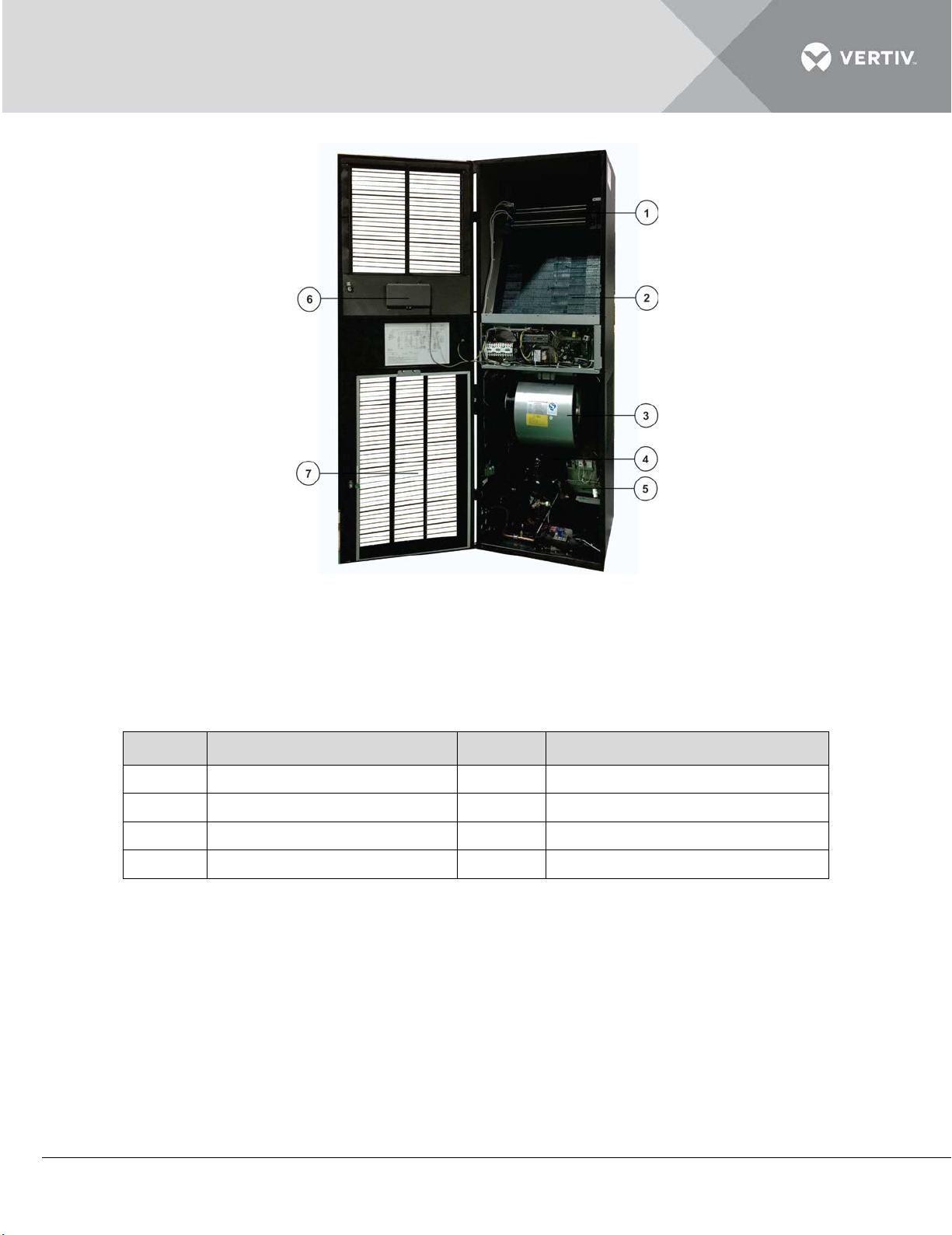
Figure 1-2
Item
Description
Item
Description
1
Heater
2
Evaporator
3
Centrifugal Fan
4
Compressor
5
Infrared Humidifier
6
Microcontroller Display
7
Filter
Listing 1.2
In the following sections, take a look at the list of components used in the Liebert DM AC series.
1.3.1 Compressor
The Liebert DM AC series models comprise of a scroll compressor which has a host of promising
features such as low operating noise, less vibration and high reliability. Its compactness, smooth
compression with scroll operation and high energy efficiency ratio makes it an ideal compressor to
bank on for the DM series.
Vertiv | Liebert DM Series Precision Air Conditioner | User Manual 5
Page 17
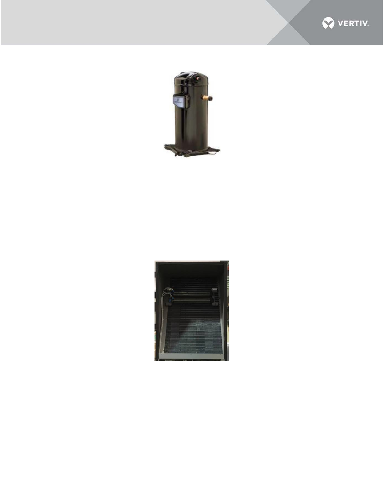
Figure 1-3 shows the image of a compressor.
Figure 1-4
1.3.2 Evaporator
Heat exchanger design and appropriate air distributions are important factors that determine optimum
performance. The Evaporator used in the Liebert DM AC models consists of a fin-tube heat exchanger
for higher efficiency. The sophisticated design of the distributor ensures that the refrigerant is
distributed evenly in each loop, thereby improving the effectiveness of the heat exchanger.
Figure 1-5 shows the image of an Evaporator.
Figure 1-5
1.3.3 Thermal expansion valve (TXV)
The thermal expansion valve controls the amount of refrigerant flow into the evaporator thereby
controlling the superheat at the outlet of the evaporator. Liebert DM consists of a thermal expansion
Vertiv | Liebert DM Series Precision Air Conditioner | User Manual 6
Page 18
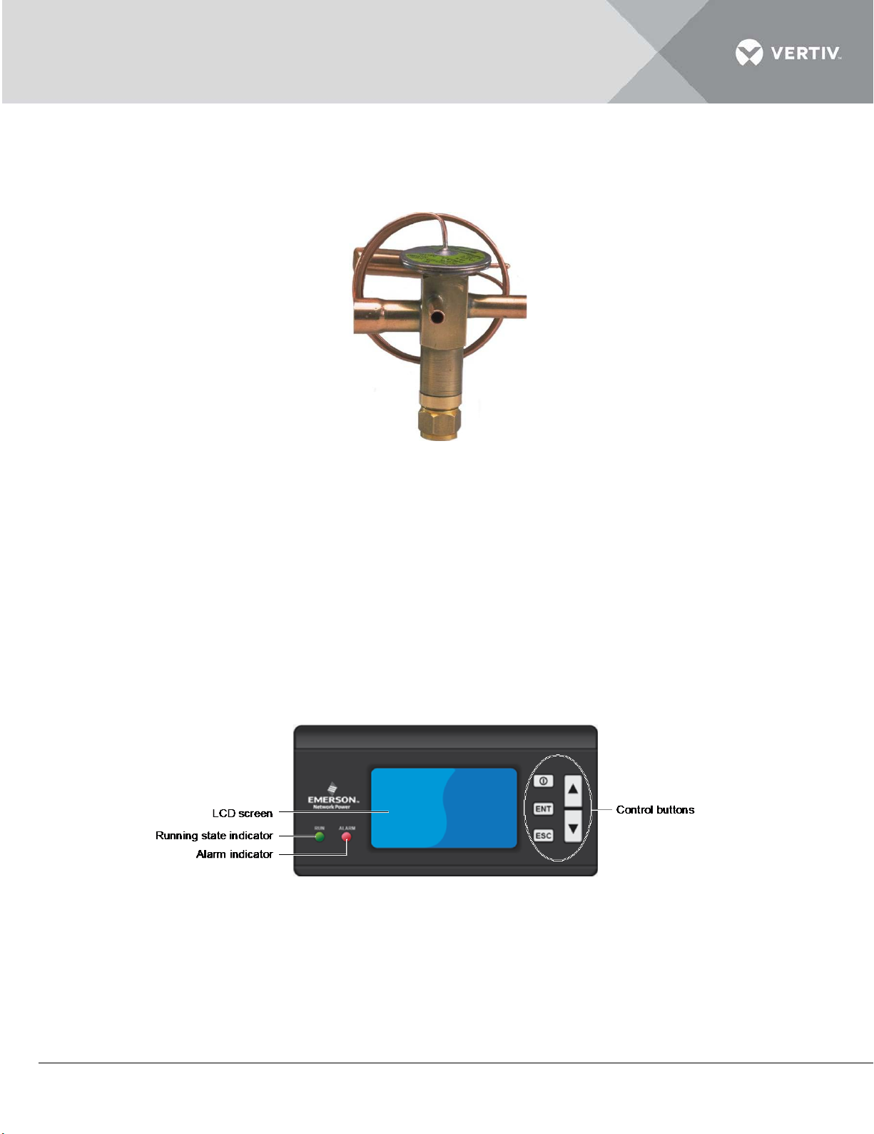
valve with external equalizer type. It collects temperature and pressure signals at the same time to
accurately regulate the refrigerant flow.
Figure 1-5 depicts the image for the TXV:
Figure 1-6
1.3.4 Micro-processing Controller
The Controller adheres to the latest and highly advanced PID regulation technology. It provides a
simple operation user interface with multi-level password protection, self-recovery upon power failure,
high-voltage & low-voltage protection, phase loss protection, automatic phase-sequence switching
upon anti-phase and rotate speed control of the outdoor fan. The expert-level fault diagnoses system
can automatically display current fault information to facilitate equipment maintenance by
maintenance personnel.
Figure 1-7 depicts the panel of the Microcontroller:
Figure 1-7
1.3.5 Strainer
The Strainer filters the impurities generated during long-term system operation and ensures normal
system operation.
Vertiv | Liebert DM Series Precision Air Conditioner | User Manual 7
Page 19
1.3.6 Filter
Moisture can have an adverse effect on the operation and life of a system in the refrigeration cycle.
To counter that effect, Filter-driers are used to filter out particles, and remove and hold moisture to
prevent it from circulating through the system. The Liebert DM AC consists of nylon filter material
with big mesh. The filter features compact structure and easy maintenance. It can be washed
repeatedly.
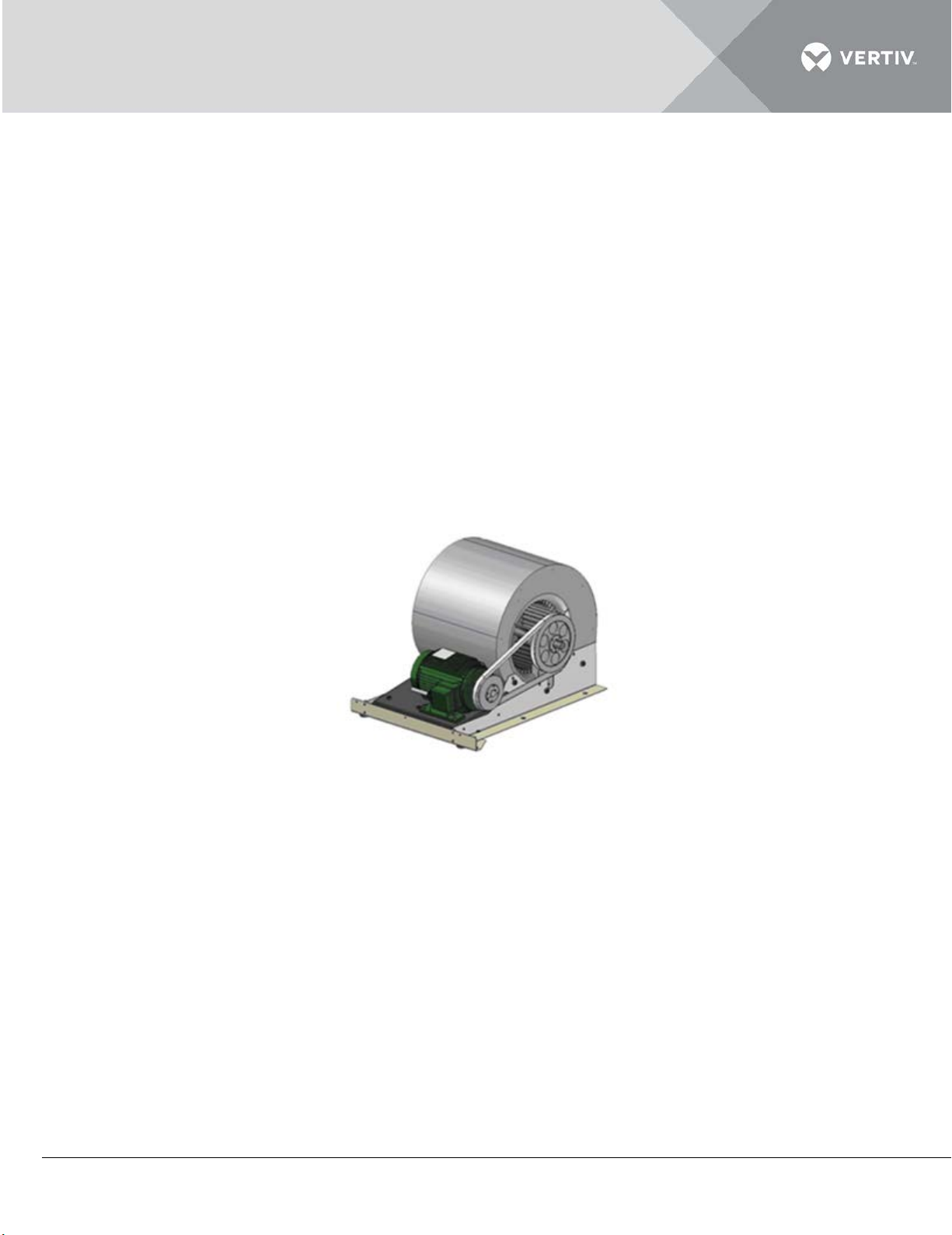
1.3.7 Centrifugal Fan
Centrifugal fans are rigid and strong metal fans. Its axial flow blades help in reducing the noise. The
single-phase motor with high performance is customized based on the power grid of base stations, so
it can work over a wide voltage range with high reliability. It features large airflow, long blowing
distance, direct driving and easy maintenance.
Figure 1-8 depicts the image for the Centrifugal Fan:
Figure 1-8
1.3.8 Condenser
The Liebert range of air-cooled condensers offers many advantages, including sharp design, antirust
aluminum cabinets, low sound levels, and reliable operations over a wide range of ambient conditions.
Figure 1-9 depicts the image of a condenser:
Vertiv | Liebert DM Series Precision Air Conditioner | User Manual 8
Page 20
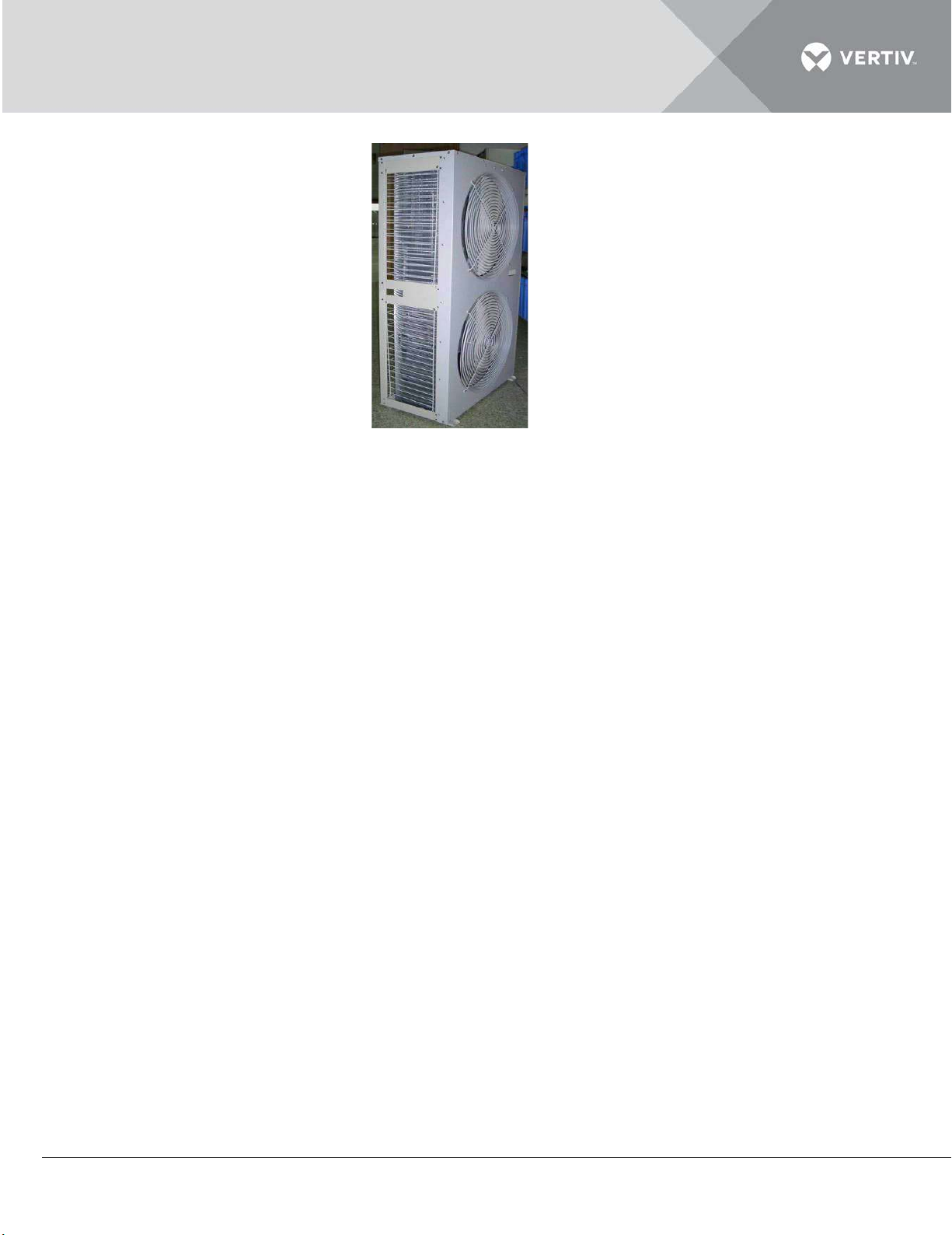
Figure 1-9
1.3.9 Sight Glass
The sight glass is a utility for observing the refrigerant state; specifically the moisture content of the
system. If the moisture content exceeds the levels of defined standards the color changes, thereby,
indicating irregularity in the moisture content.
1.3.10 Infrared Humidifier
The infrared humidifier consists of infrared humidifier lamp, water injection valve, humidifying water
dish, temperature alarm protection devices and water level alarm device.
The infrared humidifier in the Liebert DM series provides quicker and more responsive operation
which is quite important for mission-critical applications. These humidifiers reduce the dependency of
water quality and simultaneously achieve full capacity in quick time using almost any water quality.
Vertiv | Liebert DM Series Precision Air Conditioner | User Manual 9
Page 21
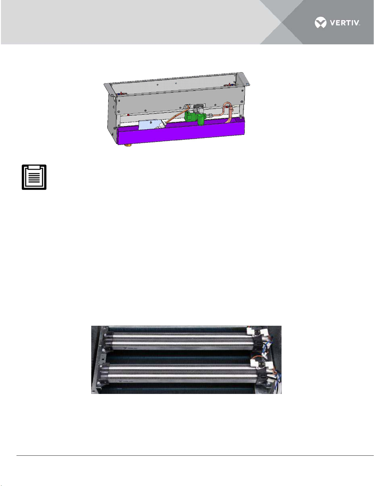
Figure 1-10 depicts the image of a Humidifier.
Figure 1-10 Humidifier
1. The electrode humidifier should be installed and tested at the factory.
2. The Liebert DM AC can control the ambient humidity only after a humidifier is installed.
1.4 Optional Components
1.4.1 Electric Heater
T
he PTC electric heaters are used as they have lower running temperatures thereby ensuring
operational safety. PTC heaters are less susceptible to overheating and therefore, are long lasting
due to less wear. Lower maintenance and smooth functioning make it an important utility in Liebert DM
AC models.
Figure 1-11 shows an image of the Electric Heater:
igure 1-11
F
Vertiv | Liebert DM Series Precision Air Conditioner | User Manual 10
Page 22

1.4.2 Remote Monitor
The Liebert DM AC communicates with the host computer through a configured RS485 port and
receives the control of the host software. Select and configure a monitoring card to realize different
monitoring functions. For the descriptions of the host monitoring software RDU-Cooling developed by
Vertiv Co., Refer to Appendix 4 RDU-Cooling Air-Conditioner Single-Unit Manager Software
Introduction.
1.4.3 Energy-Saving Card
The Liebert DM AC can monitor the maximum room temperature with the energy-saving card
located outside the unit cabinet. The card is placed in position with high heat load and temperature.
Up to four cards can be used for an AC unit. When the temperatures measured by all energy-saving
cards are lower than the set-point in ‘Sleep Mod’ and the only indoor fan is running; if the ‘Sleep Mod’
is set to ‘ENAB’, the AC unit will turn off the indoor fan and enter the sleep mode for saving the
energy.
1.4.4 Power SPD
T
he power SPD is used for the second level (C level) lightning over-voltage protection of the AC
power. It can be easily maintained and provides status indicating and alarm function.
1.5 Working Conditions
In
this section, take a look at the environmental conditions including the Operating and Storage
environment.
Vertiv | Liebert DM Series Precision Air Conditioner | User Manual 11
Page 23
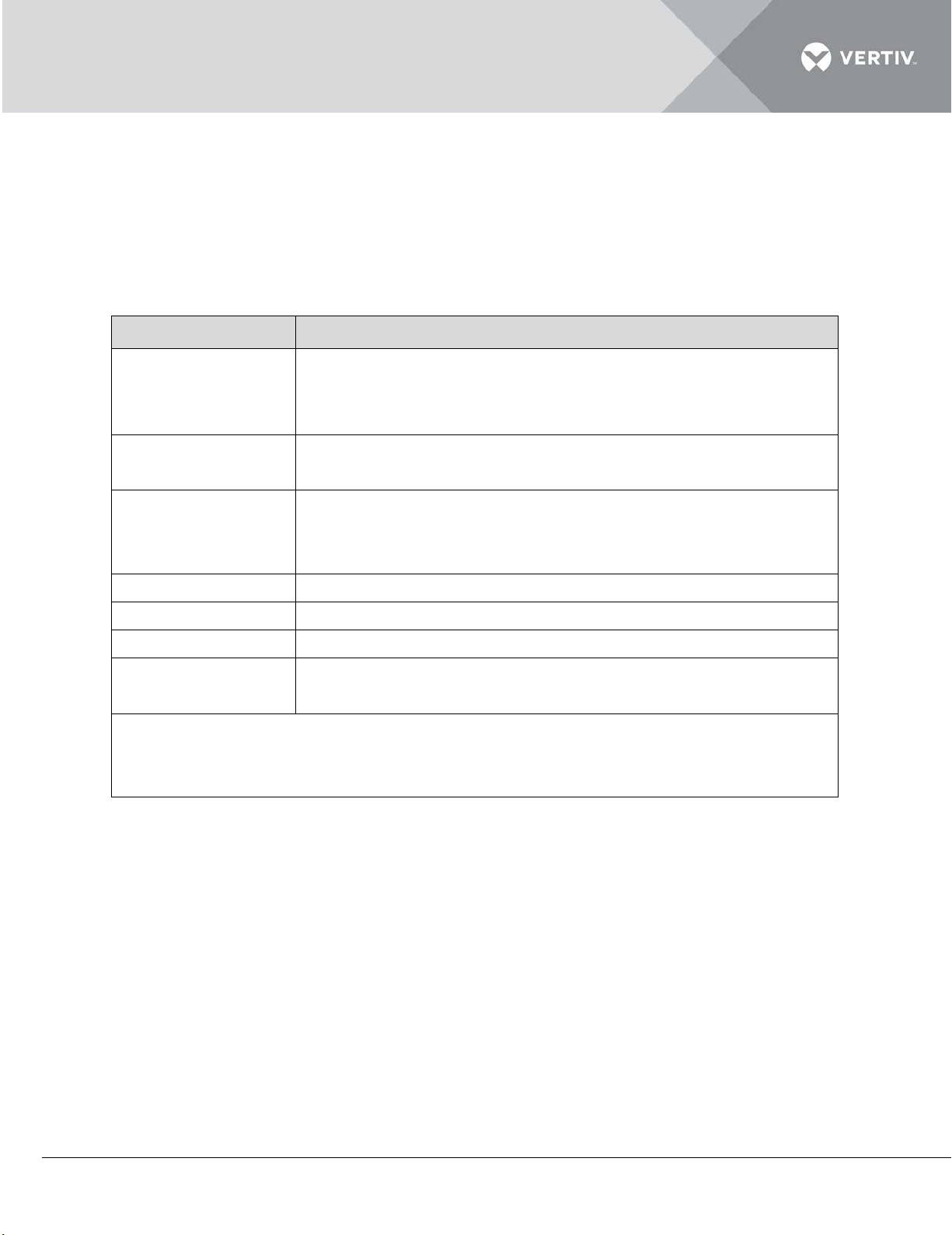
1.5.1 Operating Environment
The table in Listing 1.3 defines the Operating environment parameters including the Ambient
Temperature, Protection level, Altitude, and Voltage range.
Listing 1.3
Item Requirements
The maximum equivalent horizontal distance between the
Installation position
indoor unit and outdoor unit
Vertical distance ΔH
[2]
[1]
: 50m;
: -5m ≤ ΔH ≤ 20m
Installation mode
Indoor unit: vertical mode, mounting base ≥ 150mm;
outdoor unit: horizontal airflow mode
Indoor: 0°C ~ 40°C
Ambient
Outdoor: standard model, -15°C ~ +45°C; Low-Temp model, -
temperature
34°C ~ +45°C
Ambient humidity 30%RH ~ 80%RH
Protection level Outdoor unit: IPX4
Altitude < 1000m. Derating is required when the altitude exceeds 1000m
Operation voltage
range
380V (-15% ~ +15%), settable according to different
environments, the tolerance is 3%
Note: [1]: For the equivalent lengths of parts, refer to Listing 2.5
[2]: The value is positive if the outdoor unit is installed above the indoor unit; negative
if the indoor unit is installed above the outdoor unit
Vertiv | Liebert DM Series Precision Air Conditioner | User Manual 12
Page 24
1.5.2 Storage Environment
Item
Requirement
Storage environment
Indoor, clean (without dust)
Ambient humidity
5%RH ~ 85%RH
Ambient temperature
-40°C ~ +70°C
Total transportation and storage time should not exceed
Brand
Logo
Note
The DU PONT refrigerant adapts
The following table defines the Storage Environment parameters including the ambient humidity,
ambient temperature, and storage time conditions.
Listing 1.4
Storage time
six months. Otherwise, the performance needs to be recalibrated
Another essential aspect is the quality and the make of the refrigerant oil. Adding poor quality oil,
counterfeit oil, or oil for a different model will damage the system. The quality issue due to the wrong
refrigerant oil will result in the voiding of warranty.
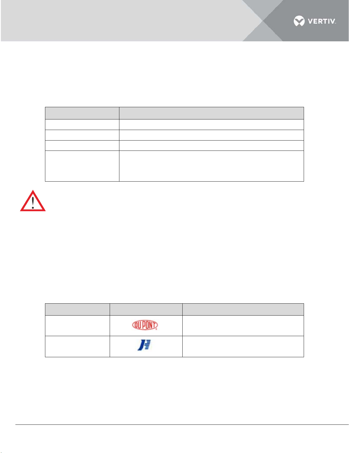
1.5.3 Refrigerant Charging Requirement
The low quality or counterfeit refrigerant will damage the system severely. Please use the refrigerant
approved by Vertiv Co., Ltd. For the system abnormality or damage caused by using other brands of
refrigerant, Refer the table in listing 1.5 for the refrigerant brands approved by Vertiv Co., Ltd.
Listing 1.5
DU PONT
custom made package
JUHUA
Vertiv | Liebert DM Series Precision Air Conditioner | User Manual 13
Page 25

Part II
INSTALLATION
Vertiv | Liebert DM Series Precision Air Conditioner | User Manual 14
Page 26
2 Installation
2.1 Pre-Installation
Pre-installation contains the following 3 sub-sections, namely –
Transportation and Movement Unpacking Inspection
2.1.1 Transportation and Movement
When transporting the system, Railroad is a preferable choice. However, if railroad transportation is
not possible, then the truck transport option is an optimal choice. One precaution is to choose roads
that do not have too many bumps and if any, avoid it as much as possible.
It is recommended that equipment like an electric forklift is utilized for these heavy duty systems.
Move the equipment to a location which is in the vicinity of the installation site.
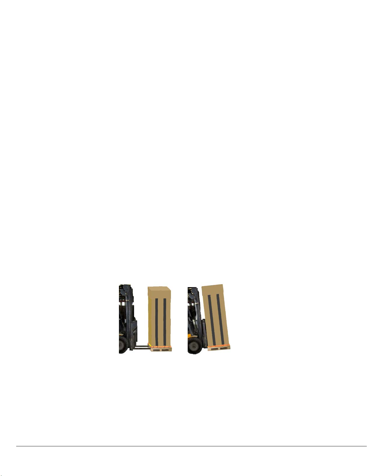
If an electric forklift is used, insert the tines of the forklift below the pallet as displayed in Figure 2-1.
Align the tines with the center of gravity to prevent the equipment from falling over. Figure 2-1
depicts the way the tines of the forklift are inserted below the pallet and in the same image; the
graphic to the right indicates that the tines are aligned with the center of gravity to prevent the
equipment from falling over:
Figure 2-1
In the previous Figure 2-1, the air conditioner is lifted using the forklift truck and is aligned with the
center of gravity. While moving the indoor unit, the obliquity has to be maintained at an angle of 75°
to 105°.
Vertiv | Liebert DM Series Precision Air Conditioner | User Manual 15
Page 27
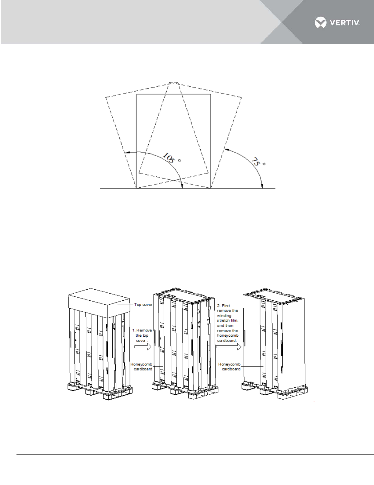
Figure 2-2 depicts the 75° to 105° obliquity that is suitable to move the air conditioning package to the
vicinity of the desired location:
Figure 2-2
2.1.2 Unpacking
The cabinet uses a honeycomb cardboard and winding stretch film for packaging purposes. Shift the
product to a location closer to the final installation site prior to unpacking the unit.
Initially, remove the top cover and winding stretch film. Next, remove the honeycomb cardboard as
depicted in Figure 2-3.
Figure 2-3
Vertiv | Liebert DM Series Precision Air Conditioner | User Manual 16
Page 28
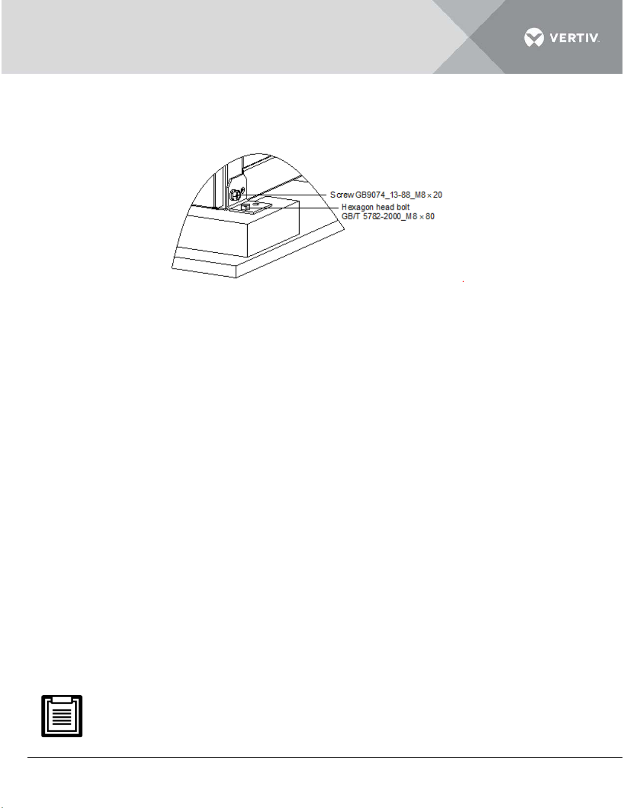
The unit is fixed on the packing pallet with M8*20 and M8*80 screws. Use a 17 mm open-end spanner,
ratchet spanner, or sleeve to remove the screws.
Figure 2-4 to shows the schematic diagram:
Figure 2-4
2.1.3 Inspection
Moving forward, check the system fittings and its components against the packing list to ensure that
everything is in place and the assembly is intact. If any parts or components are missing or damaged,
immediately report to the carrier about the same. If hidden damages are observed, then contact the
local offices of that carrier as well as Vertiv Co., at the earliest.
2.2 Installation Preparation (Site Preparation)
The Liebert DM AC series of air conditioners is streamlined for maintaining a favorable environment
for data centers, computer rooms, and similar ecosystems. Strict adherence to the installation
procedures is mandatory in order to ascertain proper installation of the air conditioner.
2.2.1 Equipment Room Requirement
The equipment room must be prepared to ensure a smooth operation flow and obtain accurate
results. The equipment room must meet the standards for appropriate ventilation and heating. The
design specifications for the air conditioners must be ideal and should match the energy-efficient
design standards.
Following are the requirements for maintaining a favorable room environment prior to installation:
The equipment room should be well insulated and have a sealed damp-proof layer.
The most important elements for maintaining normal environmental control in the conditioned room
are damp proof and heat preservation.
Vertiv | Liebert DM Series Precision Air Conditioner | User Manual 17
Page 29
The outside air will add to the loads of heating, cooling, humidifying and dehumidifying of the system. It is
recommended that the inhalation of outside air should be kept below 5% of the total indoor airflow.
All the doors and windows should be properly sealed to minimize the leakage and the seams should be as narrow
as possible.
Vertiv Co. recommends that the site preparation is defined as per the requirements. However, if these
requirements are not met, rectifications must be made on the site so that it complies with the specified
requirements and conditions. However, if the recommended rectifications or modifications are not
implemented, then Vertiv Co. does not guarantee the accuracy and precision of the temperature and
humidity provided by the Liebert DM model. One important aspect to be considered is that the indoor
unit must not be used for the outdoor environment.
2.2.2 Installation Space requirements
Air conditioners in the Liebert DM AC series are advanced precision air cooling units and therefore,
these air conditioners must be installed, preferably in a capacious floor space to ensure its normal
operation.
The Liebert DM AC can generate condensate water. Water leakage can cause damage to other precise
equipment nearby. Do not install the AC units in the vicinity of any precision equipment. The installation
site must provide drainpipes.
Vertiv | Liebert DM Series Precision Air Conditioner | User Manual 18
Page 30
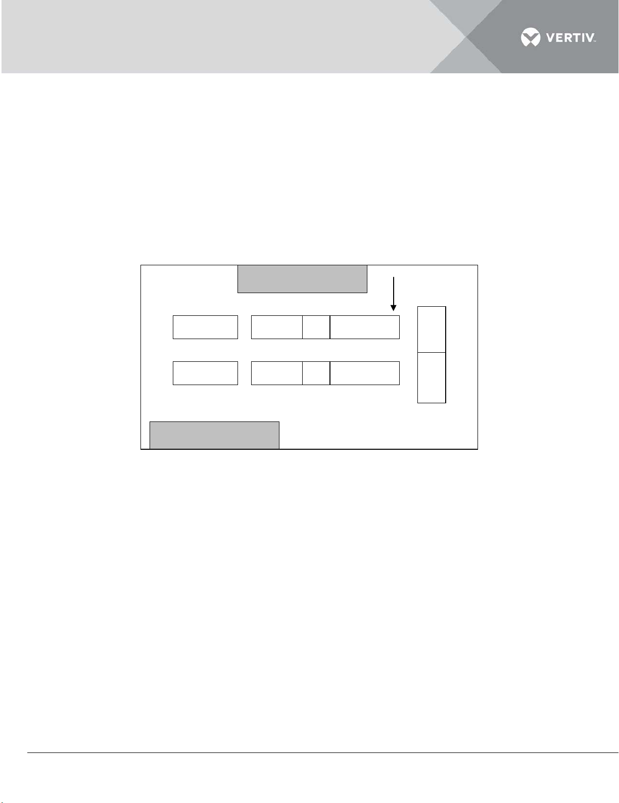
The installation location requirements are given as follows:
Not recommended location
location
Recommended
• Avoid locating the indoor unit in confined areas that affect the airflow pattern, shorten cooling cycles and
result in down-draft and air noise.
• Avoid locating the indoor unit in an alcove or at the extreme end of a long, narrow room.
• Avoid locating multiple indoor units close to each other. This can result in crossing air patterns, uneven
loads and compete for operation.
• Do not install additional devices (such as smoke detectors) over the cabinet for facilitating routine
maintenance.
The following Figure 2-5 depicts the installation location of the indoor unit.
Figure 2-5
Vertiv | Liebert DM Series Precision Air Conditioner | User Manual 19
Page 31
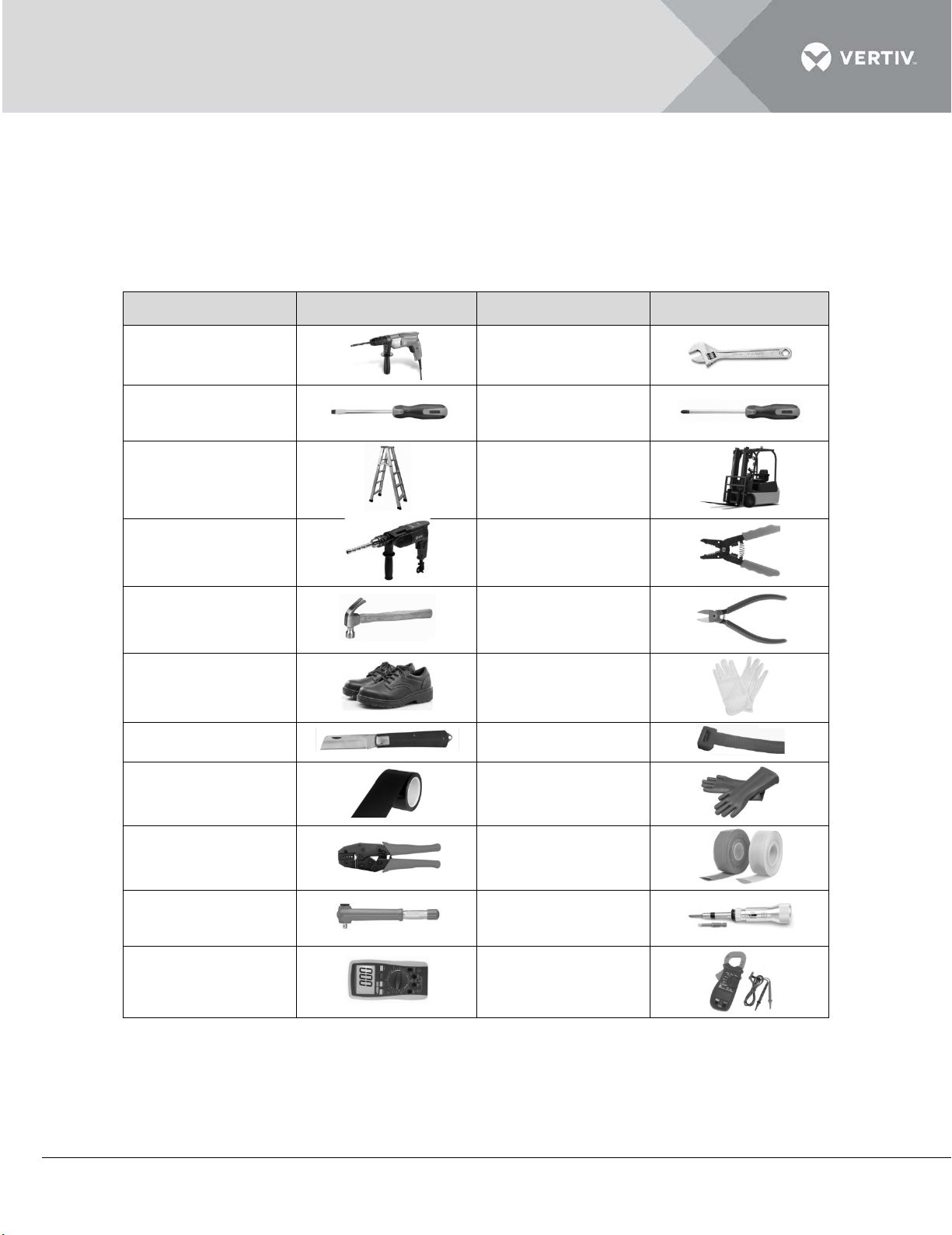
2.2.3 Installation Tools
Name
Drawing
Name
Drawing
Slotted
Cross head
Insulated torque
Torque
The following table in listing 2.1 shows the generic toolsets and utilities used in the installation and
maintenance process:
Listing 2.1
Electric hand drill
screwdriver
Stepladder
Drill
Claw hammer
Insulating shoes
Electrician knife
Insulating tape
Adjustable wrench
screwdriver
Forklift
Wire cutting pliers
Diagonal cutting
pliers
Antistatic gloves
Cable ties
Insulating gloves
Crimping pliers
wrench
Multi-meter
tube
screwdriver
Clip-on ammeter
The tools mentioned in listing 2.1 are generic and commonplace; however, depending on various factors
such as site environment, cables, installation equipment, and on-site electrical connections these tools
may vary in a real-time scenario.
Vertiv | Liebert DM Series Precision Air Conditioner | User Manual 20
Heat shrinkable
Page 32
Ensure that the tools used in the installation, operation, and maintenance processes are insulated. This
safety measure is important for professionals and service personnel who work with this Liebert DM
range air conditioner.
2.3 Mechanical Installation
Proper installation is important to achieve optimal performance and prolong the product life. In this
section, the mechanical installation will be discussed in detail to help the personnel get to grips with the
installation process.
Before proceeding with the mechanical installation, the following safety precautions need to be taken
into account:
Prior to installation, ensure that the installation procedures have been read and implemented as per
the requirement. (Refer to section 2.2 for the Installation Site preparation). Check if any modifications
are made to the plumbing, wiring, or ventilation facility before mounting the equipment. Once the
installation preparations are taken into consideration, move on to the next step in the installation
process, and eventually set up the system.
The Liebert DM cooling units are designed for split-floor installation. The indoor unit must be installed
on the floor of the equipment room or computer room. The outdoor unit must be installed outdoors or
on the floor of the other rooms as per the building architecture.
Industry-wide standards are followed for the selection, layout, and fixing of pipes.
Several factors such as pressure drop, compressor oil return, noise reduction, and vibration are
considered during the design and installation process.
Follow the design drawings strictly when installing the equipment. Reserve space as per the
maintenance and serviceability instructions in the previous chapter on Installation Preparation. The
manufacturer’s engineering dimension drawings must be taken as a reference while installing the
equipment.
2.3.1 System arrangement during installation
The system general arrangement diagram is depicted in Figure 2-6.
Vertiv | Liebert DM Series Precision Air Conditioner | User Manual 21
Page 33
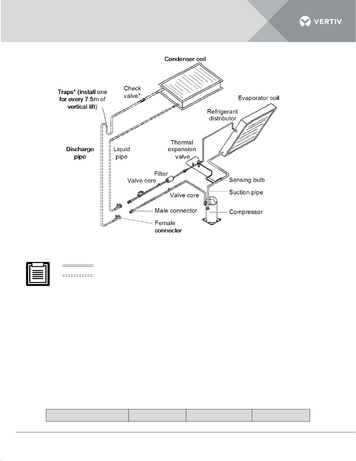
Figure 2-6 General arrangement diagram
Actual cooling capacity
Pipe length (m)
Discharge pipe
Liquid pipe
1. : Factory piping
2. : Field piping (by technicians)
The following points should be considered before checking out the overall layout diagram:
The single system is used as an example to describe the entire system.
Vertiv Co. staff and qualified professionals lay out the piping in the laboratory.
Piping is done by technicians.
Components (marked with *) are not supplied by Vertiv Co. but are recommended for proper circuit
operation and maintenance.
Additional components (marked with +) are required when the equivalent length exceeds 30m.
The standard pipe sizes are shown in Table within Listing 2.2.
Listing 2.2
Vertiv | Liebert DM Series Precision Air Conditioner | User Manual 22
Page 34
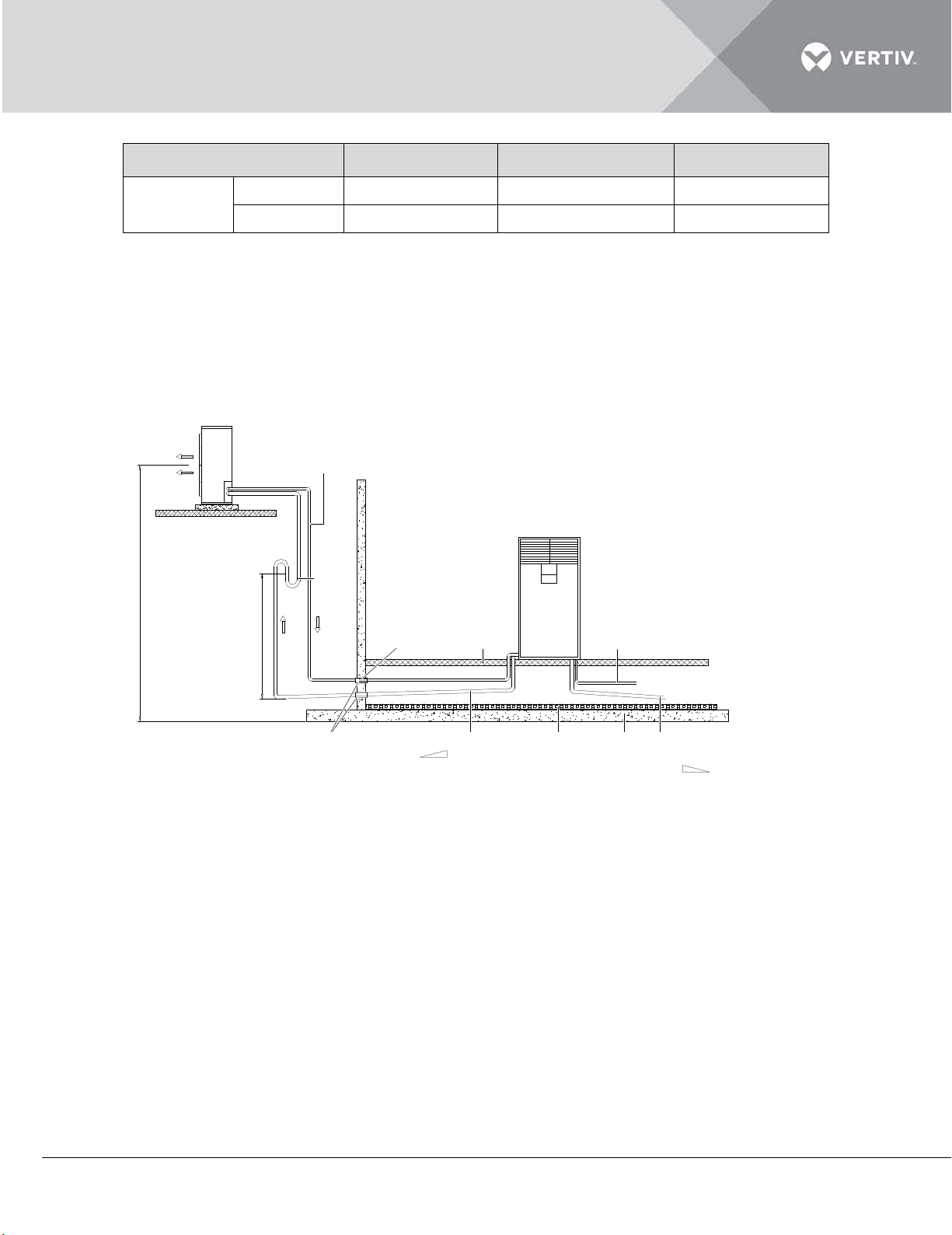
OD
OD
Liebert DM
AC series
7.5kW unit
5
1/2” (12mm)
3/8” (10mm)
12.5kW unit
5
5/8” (16mm)
1/2” (12mm)
Outdoor unit
Floor
Isolataion
floor
Max. 20m
1:200
7.5m
1:200
Insulation
material
Trap
Liquid pipe (not be exposed to sun)
Sealed
Protection
tube
Discharge pipe (slope)
Indoor unit
Condensation water
drain pipe (to outdoor)
Humidifier canister water
supply pipe (to water tap)
Humid ifier water supply p ipe
( to water tap )
2.3.2 System Installation Mode
The Liebert DM AC is available in two installation modes:
Outdoor unit installed higher than Indoor unit
Indoor unit installed higher than Outdoor unit.
The schematic diagram of Outdoor Unit installed higher than Indoor unit is depicted in Figure 2-7
Figure 2-7 Outdoor unit above indoor unit
Vertiv | Liebert DM Series Precision Air Conditioner | User Manual 23
Page 35
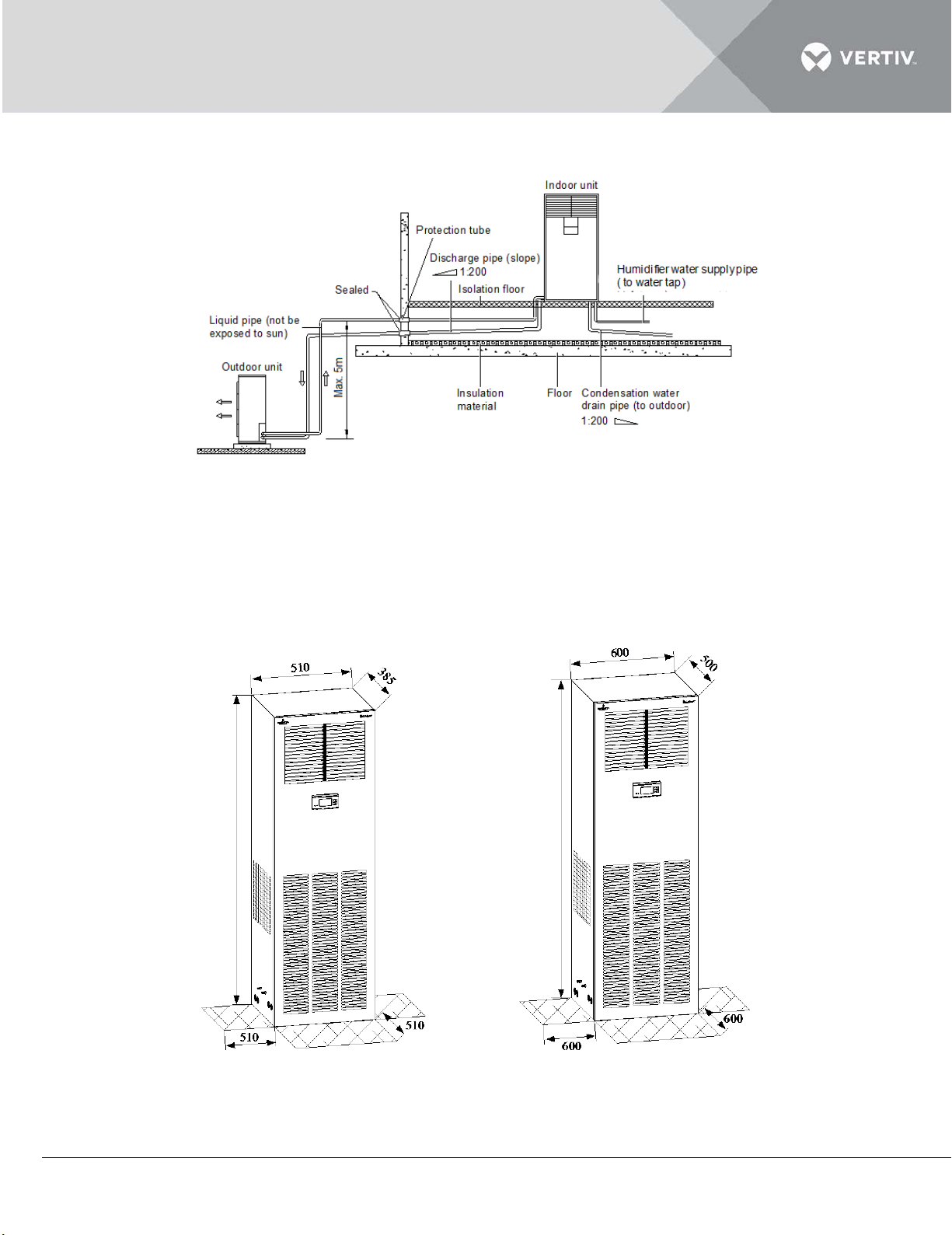
The schematic diagram of Indoor Unit installed higher than Outdoor unit is depicted in Figure 2-8
1850
1975
Figure 2-8 Indoor unit above outdoor unit
2.3.3 Product Dimensions
The dimensions and weight of the indoor unit are displayed in Figure 2-9 and in the table within Listing
2.3
DME07kW DME12kW
Figure 2-9 Dimensions of indoor unit (unit: mm)
Vertiv | Liebert DM Series Precision Air Conditioner | User Manual 24
Page 36
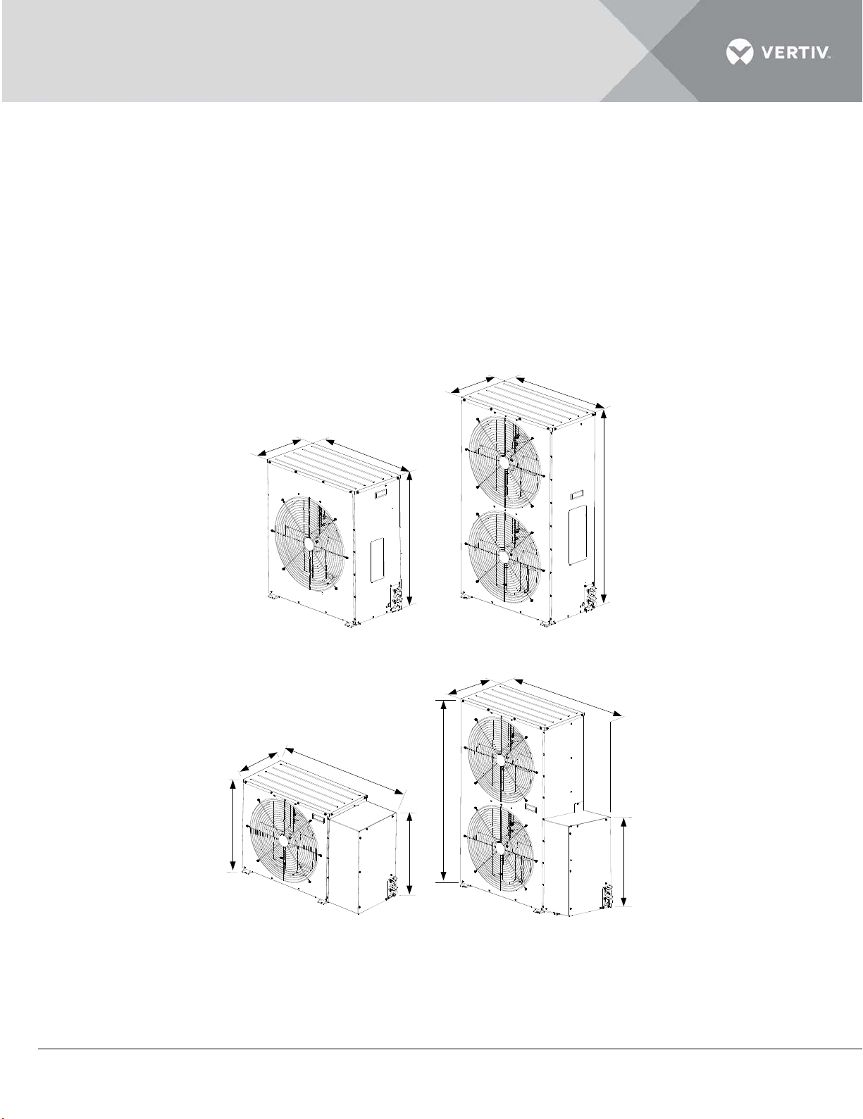
The shadows in Figure 2-10 indicate a reasonable installation and service space. The two sides of the
352
787
829
1240
352
787
352
1037
575
1238
352
1037
575
829
unit need air inlet. Adequate service space must be reserved for the unit to facilitate maintenance.
The AC unit equipped with a heater should be kept a distance of minimum 150 mm from combustible
substance. When testing the AC unit, keep the external static pressure below 150Pa lest the air
volume becomes too low and the heater becomes too hot.
2.3.4 Outdoor unit
The mechanical parameters of the outdoor unit are shown in Figure 2-10, 2-11 and
Table 2.3
2-10 Dimensions of standard outdoor unit (unit: mm)
Figure 2-11 Dimensions of Low-Temp outdoor unit (unit: mm)
Listing 2.3
Vertiv | Liebert DM Series Precision Air Conditioner | User Manual 25
Page 37
Model
Cooling capacity (kW)
Dimensions (W × D × H)
in mm
Net weight
(kg)
Indoor
unit
7.5
510 × 385 × 1850
100
12.5
600 × 500 × 1975
155
7.5
787 × 352 × 829
40
12.5
787 × 352 × 1240
60
7.5
1037 × 352 × 829
55
12.5
1037 × 352 × 1238
90
510
385
Rubber cushion
(8mm ~ 10mm thickness)
Steel plate (60 60 4)
H > 150
Rubber cushion
(8mm thickness)
Angle iron (30 30 3) or
square tube (25 25 3)
×
×
×
×
×
×
600
500
H > 150
Installation hole for
expansion bolt (M6 50)
Rubber cushion
(8mm ~ 10mm thickness)
Steel plate (60 60 4)
Rubber cushion
(8mm thickness)
Angle iron (30 30 3) or
square tube (25 25 2)
×
×
×
×
×
×
×
Outdoor
Standard model
unit
Low-Temp model
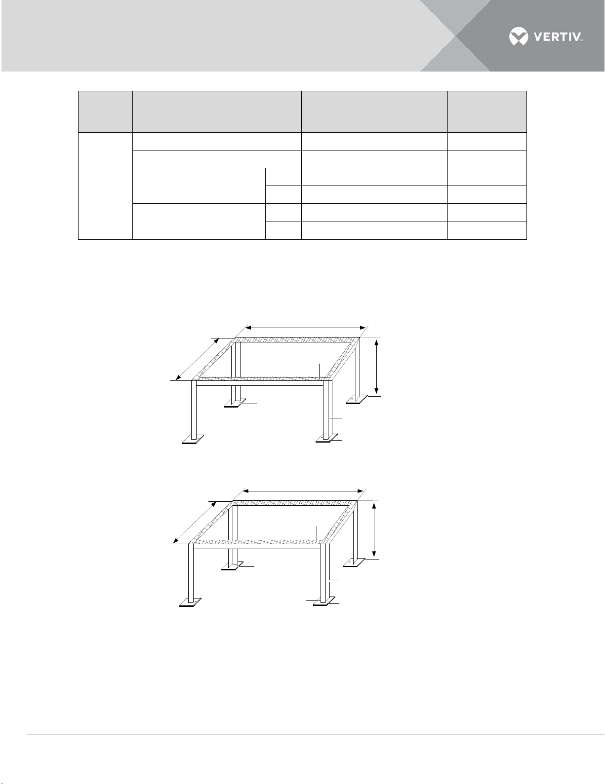
2.3.5 Indoor Unit Installation
1. The outline and dimensions of the mounting base are shown in Figure 2-12.
Figure 2-12 Mounting base of DME07kW indoor unit
Figure 2-13 Mounting base of DME12kW indoor unit
Vertiv | Liebert DM Series Precision Air Conditioner | User Manual 26
Mounting base (unit: mm)
Page 38
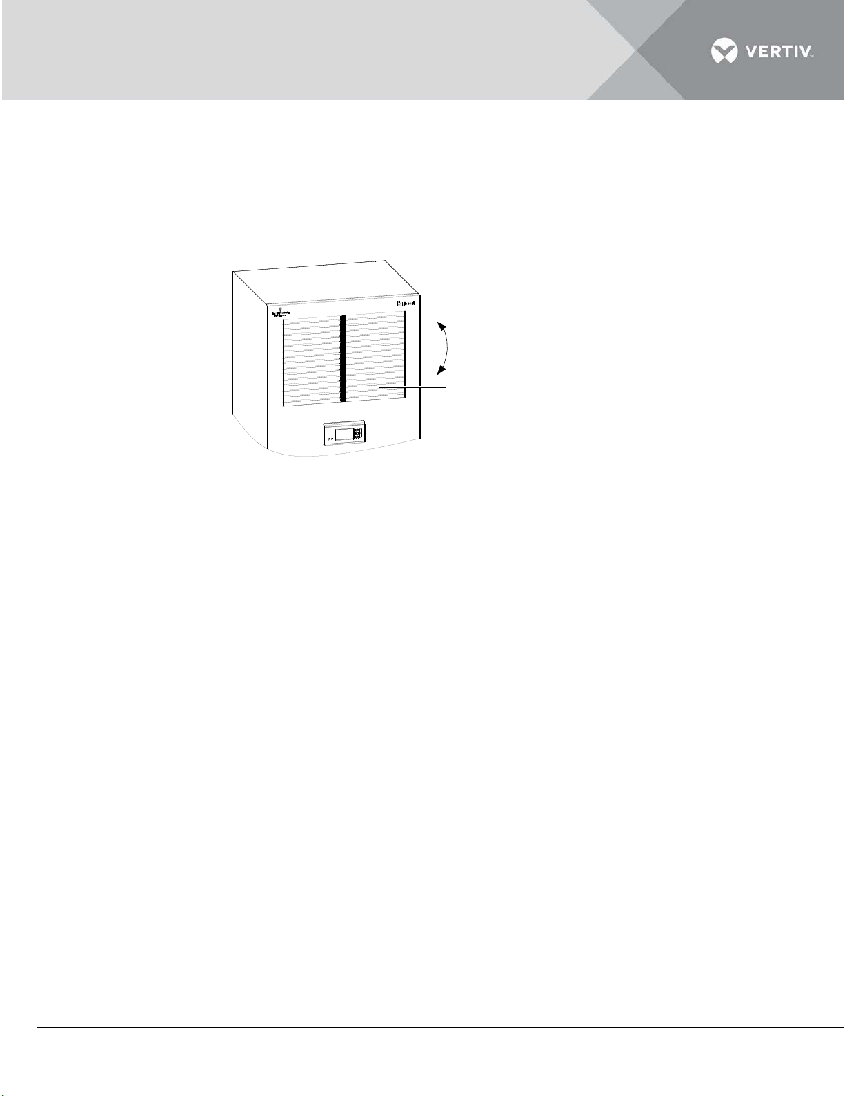
2. Lay a rubber cushion with 8mm ~ 10mm thickness on the mounting base, as shown in above figure.
Grill
The grilles can be rotated
following the arrow direction
3. Place the indoor unit onto the mounting base and secure it with nuts, spring washers, flat washers
and bolts.
4. Rotate the grilles to regulate the airflow direction of the indoor unit, and the regulating angle is 45°,
as shown in Figure 2-14.
Figure 2-14 Regulating airflow direction
2.3.6 Outdoor Unit Installation
The installation location requirements are mentioned as follows:
Install the outdoor unit in a place which is secure and easy for maintenance. Do not install it on ground-level sites
with public access and be away from residential areas.
Do not locate it directly in the environment that requires low noise.
To ensure heat dissipation effect, locate it in a clean area, which is away from loose dirt and foreign matter to
avoid clogging the heat exchanger.
Do not locate it in the vicinity of steam, hot air and exhausts.
Keep a clearance of more than 450 mm between the outdoor unit and the wall, obstruct and adjacent devices.
Avoid areas where snow will accumulate at the air inlet and outlet side of the outdoor unit.
Prepare a solid base capable of supporting the outdoor unit weight (refer listing 2.3). The base should be at least
50mm higher than the surrounding ground and 50mm larger than the dimensions of the outdoor unit base, as
depicted in Figure 2-17.
2.3.7 Procedure
Place the outdoor unit on the base.
Secure the outdoor unit onto the base with expansion bolts. The installation hole size of the base is shown in
Figure 2-15 and Figure 2-16.
Vertiv | Liebert DM Series Precision Air Conditioner | User Manual 27
Page 39
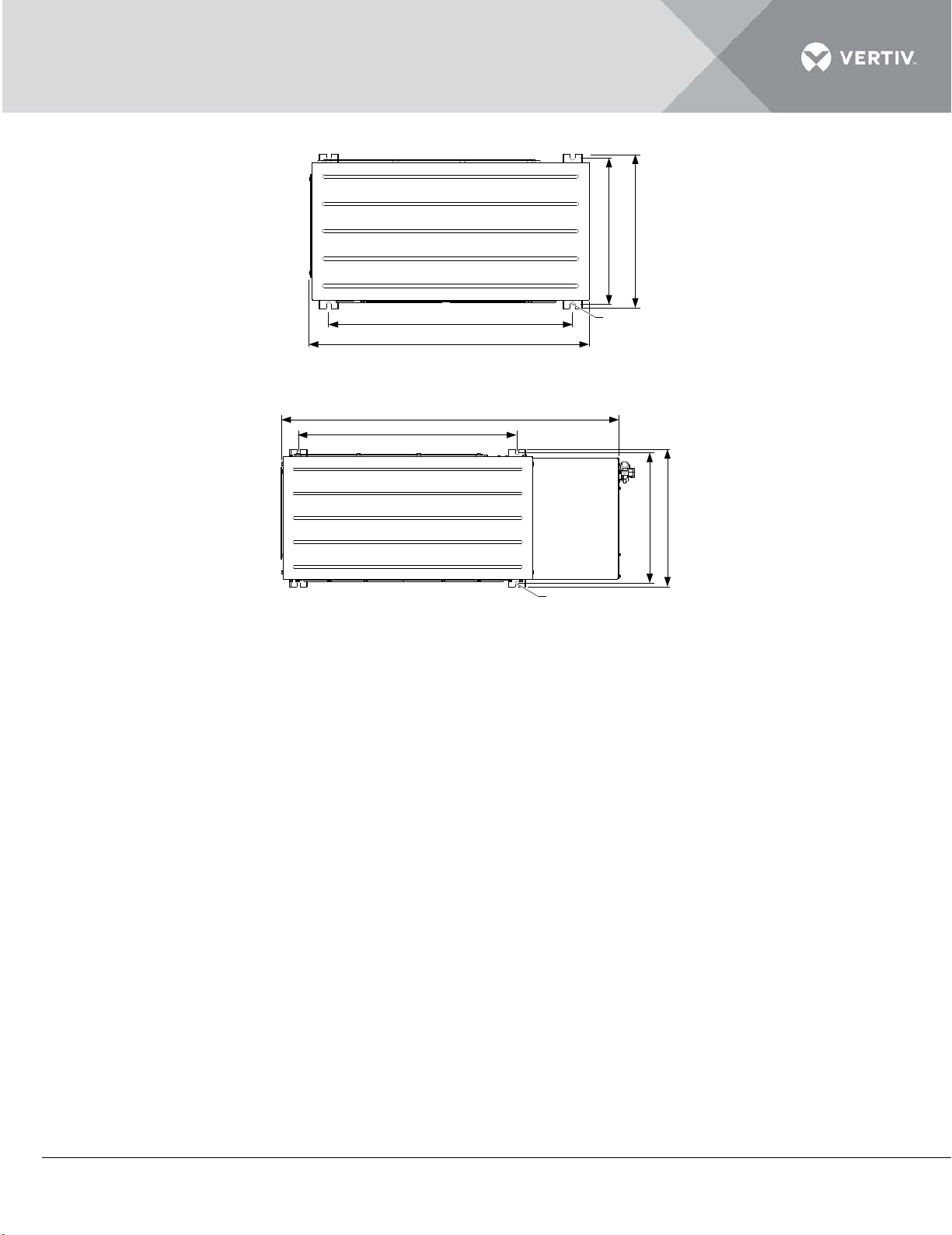
Figure 2-15 Installation hole dimensions of standard outdoor unit base (top view, unit: mm)
787
374
680
R6
394
680
1037
374
394
R6
Figure 2-16 Installation hole dimensions of Low-Temp outdoor unit base (top view, unit: mm)
Vertiv | Liebert DM Series Precision Air Conditioner | User Manual 28
Page 40
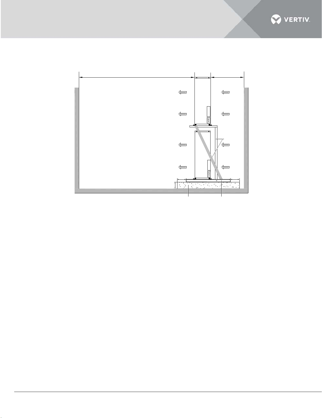
If multiple outdoor units are needed to be installed one above the other, refer
Bracket
4m 0.5m
50mm50mm
Min. 50mm
Outdoor unit base
Base
Airflow
Airflow
Out-
door
unit
Outdoor
unit
Note:
1. Use 5# angle iron for bracket, when
two units are installed with one above
the other.
2. Use 6.5# channel steel for bracket, when
three units are installed with one above the
other.
Figure 2-17 to install them.
Figure 2-17
2.3.8 Piping for AC Unit
General Principles
Copper pipes with a quick thread connector should be used to connect to the indoor and the outdoor unit. If the
pipe length exceeds the standard pipe length (refer listing 2.2) and the straight copper pipe is used, piping joints
must be brazed.
Standard industry procedures must be followed in the selection and placement of pipe, and charging with
refrigerant (only when the pipeline is too long). The standard refrigerant of the AC unit is R407C.
Considerations must be given to pipeline pressure drop, oil return to the compressor, to avoid oil leakage and
clogging in parts of the system and minimize noise and vibration to the greatest extent.
Always consult Vertiv Co. before installation on the measures such as, using extended piping kit are needed, if
the equivalent length exceeds 30m, or if the vertical distance between the indoor unit and the outdoor unit
exceeds the values as mentioned in Table within Listing 2.4.
Vertiv | Liebert DM Series Precision Air Conditioner | User Manual 29
Page 41
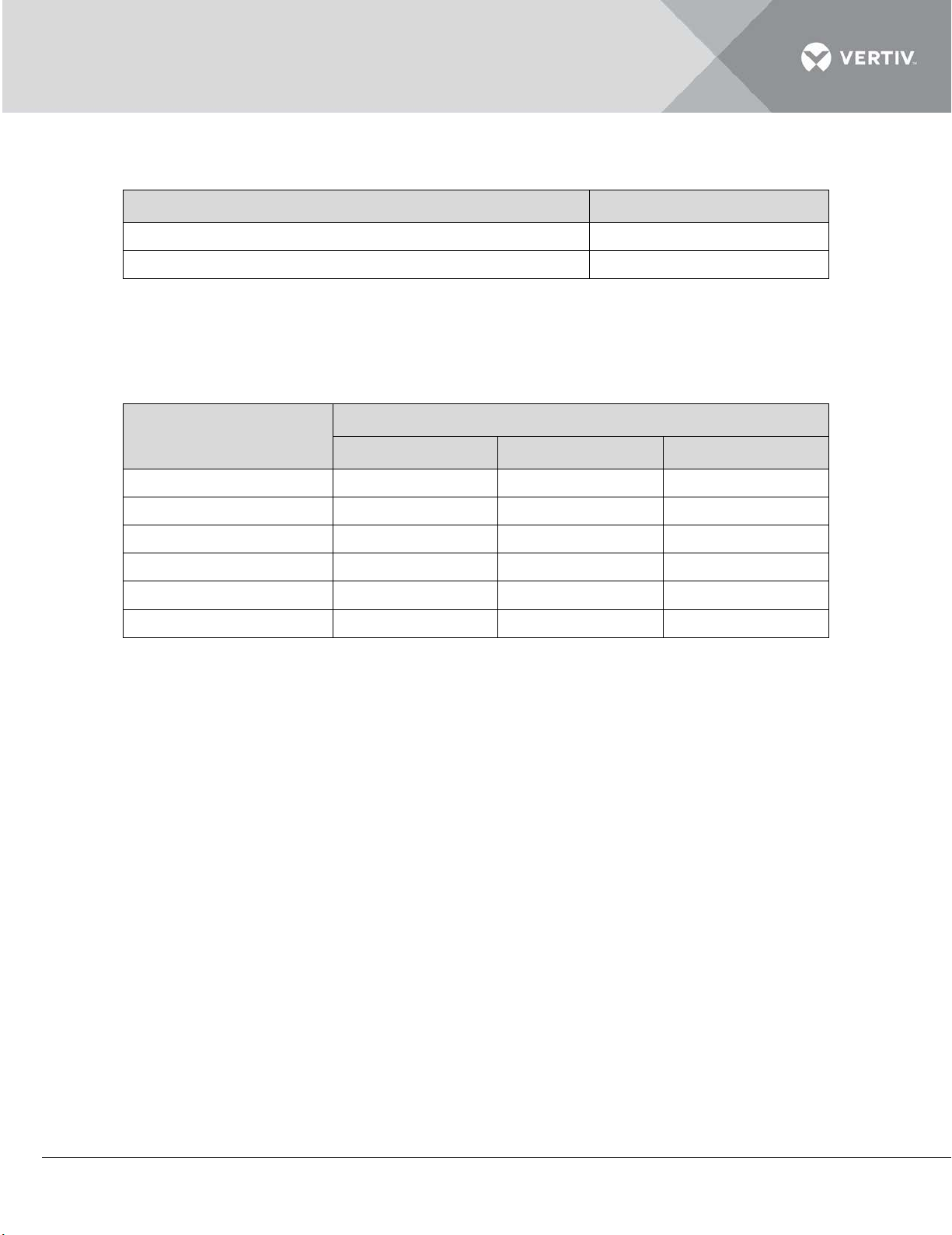
Listing 2.4
Relative position
Value
Outdoor unit installed higher than indoor unit
Maximum: 20m
Outdoor unit installed lower than indoor unit
Maximum: 5m
Liquid pipe OD (inch)
Equivalent length (m)
90° elbow
45° elbow
T-type three way
3/8
0.21
0.10
0.76
1/2
0.24
0.12
0.76
5/8
0.27
0.15
0.76
3/4
0.3
0.18
0.76
7/8
0.44
0.24
1.1
1-1/8
0.56
0.3
1.4
The equivalent length of each part is given in Table within Listing 2.5. The resistance loss caused by elbows and
valves has been taken into consideration. The installer should confirm if these values are appropriate for site
conditions.
Listing 2.5
2.3.9 Installation Notes Of Connector
Utmost care should be taken while connecting the quick thread connector. Read the following steps
before carrying out the connections:
1. Remove the dust-proof caps.
2. Carefully wipe coupling seats and threaded surface with a clean cloth.
3. Lubricate the male thread with the refrigerant oil.
4. Thread the coupling halves together by hand to ensure that the threads mate properly.
5. Tighten the coupling body’s hexagon nut and union valve until a definite resistance is felt.
6. Use a marking pen to draw a line lengthwise from the coupling union nut to the bulkhead. Tighten
the nuts an additional quarter turn with two wrenches. The misalignment of the lines indicates how
much the coupling has been tightened. The final quarter turn is necessary to ensure that the joint
does not leak. Two wrenches must be used to cooperate with each other during connection
because using one wrench can damage the coupling copper lines easily.
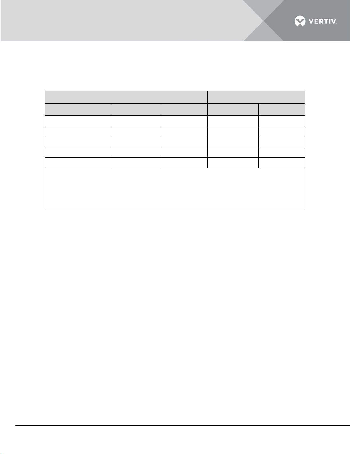
The recommended torque values are mentioned in Table within Listing 2.6.
Listing 2.6
Vertiv | Liebert DM Series Precision Air Conditioner | User Manual 30
Page 42
Coupling size
Torque value (N-m)
5/8”
7 ~ 8
3/4”, 7/8”
25 ~ 32
2.3.10 Required Pipe Connections
Refer Figure 2-7; the required pipe connections are mentioned as follows:
The refrigerant pipe between the indoor unit and the outdoor unit (discharge pipe and liquid pipe).
Drain pipe of the indoor unit.
The following pipe connection is required if a humidifier is selected.
Water supply pipe to the humidifier.
Before starting, ensure that all the pipe connections have been completed without leakage after
engineering installation.
2.3.11 Connecting Refrigerant Pipe
The following notes should be considered while connecting a refrigerant pipe:
1. The indoor unit and outdoor unit should be determined based on the specifications mentioned in
Table within listing 2.7. If longer pipes are required, contact Vertiv Co. or the concerned sales agency.
2. The liquid pipe is the refrigerant liquid pipe of the outdoor unit outlet. Thereby, a reasonable pipe
diameter and length should be selected for the liquid pipe to ensure that the pressure drop of the
refrigerant liquid through the pipe during unit operation does not exceed 40kPa (5psi ~ 6psi).
3. The pipe should be installed and removed with utmost care so that they will not get kinked or
damaged. Ensure to use the tube benders and make all the bends before making connections to
either end.
4. If the joint mode is needed, all refrigerant piping should be connected with silver-brazed joints.
5. Check the piping supports, leakage testing, dehydration of refrigerant pipes and evacuation before
use. A vibration isolating support should be used to isolate the refrigeration pipes from the building.
6. Use a soft and flexible material to pack around the pipes to protect them from damage caused by
going through openings in walls and to reduce vibration transmission.
7. While installing the outdoor unit 7.5m higher than the indoor unit, a trap should be installed on the
discharge pipe. This trap will retain refrigerant oil in the off cycle of the compressor. When the
Vertiv | Liebert DM Series Precision Air Conditioner | User Manual 31
Page 43
compressor starts, oil in the trap will be carried up the vertical riser and return to the compressor
Model
DME07
DME12
Pipe length
D L D
L
10m
12.7
9.52
16
12.7
20m
12.7
9.52
16
12.7
30m
16
9.52
19
12.7
40m*
16
9.52
19
12.7
50m*
19
9.52
22
12.7
Note:
immediately.
Listing 2.7 Recommended pipe sizes (unit: mm)
1. A pipe extension kit is required for ‘Eq.Lgth’ marked with *.
2. D: discharge line, L: liquid line.
3. Consult Vertiv Co. if the pipe length exceeds 50m.
Vertiv | Liebert DM Series Precision Air Conditioner | User Manual 32
Page 44
2.4 Pipe connector position
B
处
气侧管
直管
1/2''-12mm
接头3/4
''-20mm
螺纹
液侧管
直管
3/8''-10mm
接头5/8
''-16mm
螺纹
加湿进水管
1/4''
铜螺母
1/4''×1/2''
转换铜螺纹接头
冷凝水排水管
(铜管接头 外径22mm)
B处放大
Liq ui d pipe: straight pipe 3/8″-10mm;
co n nector 5/8″-16mm th read
Co nd ensate water d rain
pip e(O,D,22mm)
A amplified
Humid ifier water supply p ipe
1/4 ″ copp er nut
co n nector 1/4 ″ ×1/2 ″ thread
Discharge pipe:
Straight pipe 1/2 ″-12mm;
Connector 3/4 ″ -20mm thread
A
Liq uid pipe: straight p ipe 1/2″-12mm;
co n nector 3/4″-20mm th read
Humidifier water supply pipe
1/4 ″ copper nut
co n nector 1/4 ″ ×1/2 ″ thread
Cond ensate water d rain
pipe(O,D,22mm)
Discharge pipe:
Straight pipe 5/8″-16mm;
Conn ector 7/8 ″ -22mm thread
B amplified
B
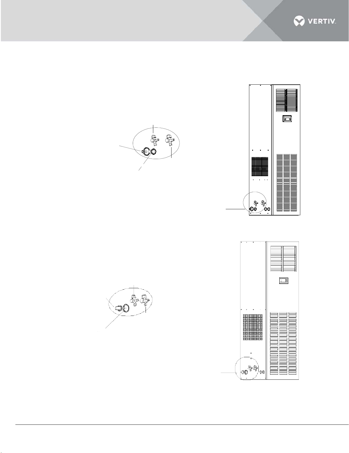
The pipe connectors inside the indoor unit are shown in Figure 2-18.
Pipe connectors inside DME07kW indoor unit
Pipe connectors inside DME12kW indoor unit
Figure 2-18
Vertiv | Liebert DM Series Precision Air Conditioner | User Manual 33
Page 45
2.4.1 Connecting discharge pipe
A
处放大
气侧管 DMC12/ DML12(直管5/8";接头7/8" -22mm
液侧管 DMC12/ DML12 (直管1/2"
;
3/4" -20mm 螺
气侧管 DMC07/ DML07(直管1/2" ; 3/4" -20mm 螺
液侧管 DMC 07/DML07 (直管3/8" ;接头5/8" -16 mm 螺
B处放大
B处
A处
接头
接头
A amplified
Liq uid pipe DMC 12/DML12 (straight p i pe 1/2″;
co n nector 3/4″-20mm th read)
Dis charge pipe DMC 12/DML12 (straight pipe 5/8″;
co n nector 7/8″-22mm th read)
A
Dis charge pipe DMC 07/DML07(straight pipe 1/2″;
co n nector 3/4″-20mm th read)
Liq uid pipe DMC 07/DML07(straight p i pe 3/8″;
co n nector 5/8″-16mm th read)
B amplified
A
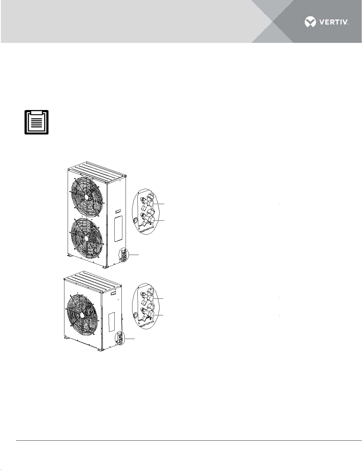
Connect one end of the discharge pipe to the discharge pipe connector of the indoor unit (shown in
Figure 2-18) and the other end to the discharge pipe connector of the outdoor unit (shown in Figure
2-19).
The discharge pipe is the pipe at the compressor discharging side. Its horizontal section should be
sloped downward, away from the compressor, with a slope of at least 1:200 (5mm down for each 1m run).
The discharge pipe should be insulated where it is routed in the conditioned space (including under a
raised floor).
Figure 2-19 Refrigerant pipe connectors of outdoor unit
2.4.2 Connecting liquid pipe
Connect one end of the liquid pipe to the liquid pipe connector of the indoor unit (shown in Figure 2-
18) and the other end to the liquid pipe connector of the outdoor unit. (shown in Figure 2-19).
Vertiv | Liebert DM Series Precision Air Conditioner | User Manual 34
Page 46

2.4.3 Connecting Drain Pipe Of Indoor Unit
The drainage pipe of the indoor unit equipped with a humidifier must be able to endure the hot water
up to 90℃. Use galvanized steel pipe, aluminum-plastic composite pipe with hot water type or PP-R
polypropylene plastic pipe with hot water type as the drainage pipe.
Connect one end of the drain pipe to the connector of condensate water drain pipe (shown in Figure
2-18). Pipe with I.D 22 mm should be used as the indoor unit provides copper pipe of O.D 22 mm to
connect with the drainage pipe. One of the accessories used is a clamp to fix the outdoor drainage
pipe.
2.4.4 Connecting Humidifier Water Supply Pipe (If Applicable)
An isolation valve should be installed on the humidifier water supply pipe for easy maintenance.
Connect the humidifier water supply pipe to the connector of the AC unit shown. The unit provides
the humidifier with copper pipe (O.D 6.35mm). The 1/4” copper nut at the end of the copper pipe and
the 1/4” × 1/2” conversion copper thread connector has been connected to the copper nut to avoid
losing them.
Where the main pipe pressure may rise above 700kPa (The main pipe pressure should be between
100kPa ~ 700kPa), a pressure reducer should be fitted.
Where the main pipe pressure falls below 100kPa, a water tank and pump system should be used.
Some products may include components required by local codes.
2.4.5 Removing Transportation Fastener And Vibration Absorber
To protect partial components from damaging and distorting due to bumping, impact and resonation;
fasteners and vibration absorbers are mounted at certain locations before delivery. Remove the
fasteners and vibration absorbers before the installation and commissioning.
Vertiv | Liebert DM Series Precision Air Conditioner | User Manual 35
Page 47
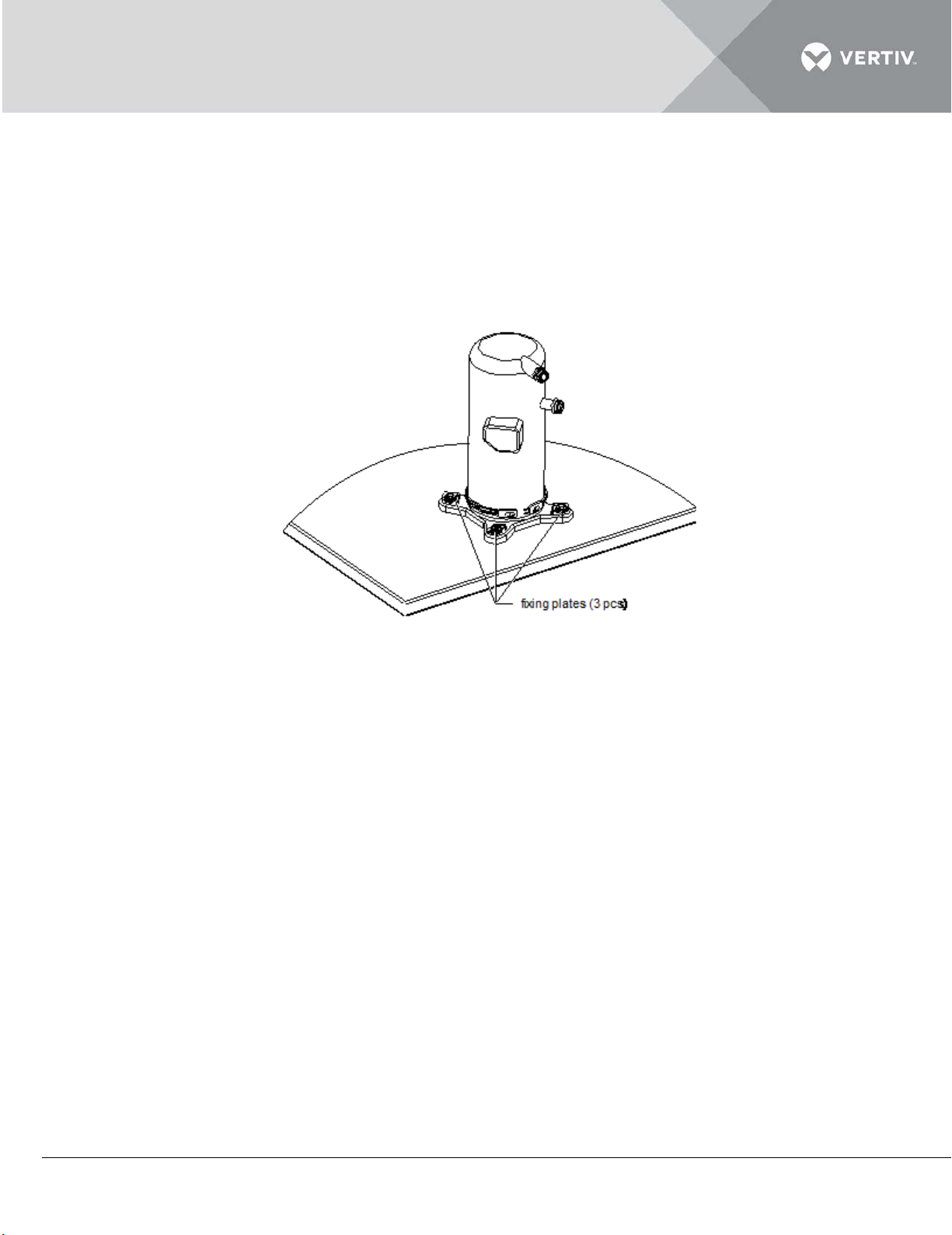
Removing transportation fixing plate of the compressor
To reduce the compressor's operational noise and vibration; the vibration absorbing cushions are
added to the compressor base. However, such a method cannot suitably restrain the equipment
vibration during transportation and would result in loosened connections and wear of certain parts.
To prevent this, three U-shaped fixing plates are added to the compressor base, as shown in Figure
2-20.
Figure 2-20
After the installation and before commissioning, remove the three U-shaped fixing plates, and then
restore the bolts and washers. The fastening torque of the bolts is (12 ± 1) Nm.
2.4.6 Adding Refrigerant For Long Pipe System
The Liebert DM AC has been charged with appropriate refrigerant before delivery. If the connecting
pipe between the indoor unit and the outdoor unit is longer than 10m, add refrigerant to the system
in order to ensure normal system operates based on the following formula:
Adding refrigerant amount (kg) = adding refrigerant amount per meter of liquid pipe (kg/m) × total
length of extended liquid pipe (m)
Refer Table within listing 2.8 for the adding refrigerant amount per meter of liquid pipe with different
OD liquid pipes.
Total length of extended liquid pipe (m) = total length of liquid pipe (m) - 5m.
Vertiv | Liebert DM Series Precision Air Conditioner | User Manual 36
Page 48
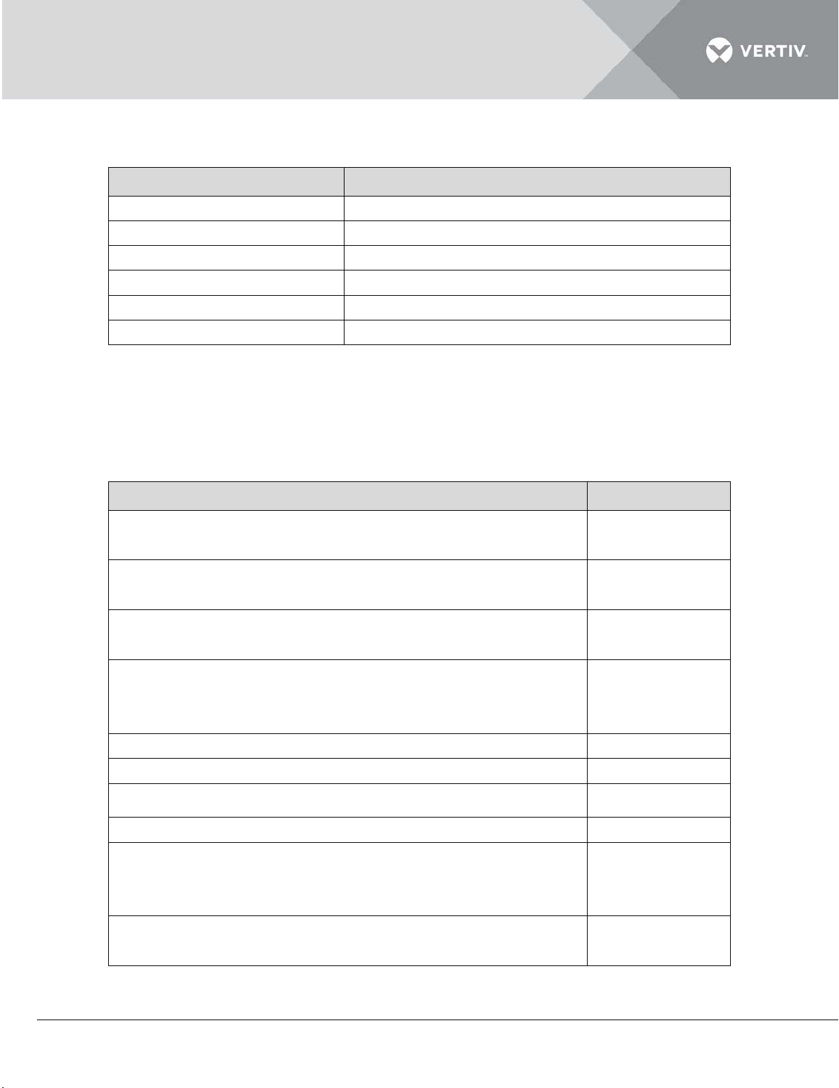
Listing 2.8
Liquid pipe OD (inch)
Adding refrigerant amount per meter (kg/m)
3/8
0.060
½
0.112
5/8
0.181
¾
0.261
7/8
0.362
1-1/8
0.618
Item
Result
Proper clearance for service access is maintained around the
The equipment is placed vertically and mounting fasteners are
The pipes between the indoor unit and outdoor unit are
Suction pipes should be insulated properly
The drain pipe is connected and insulated
All pipe connectors are tight
After installation, foreign materials in and around the equipment
Rotate the fan blades with the hand; the fan rotates freely
2.4.7 Check List
Confirm the items listed in the table under listing 2.9 on completion of Mechanical Installation.
Listing 2.9
AC unit
fastened
Check compressor mountings to avoid vibration later
completed. The quick connector valves of the indoor unit and
outdoor unit are fully opened
Water supply pipe is connected to the humidifier (if required)
are removed (such as shipping materials, construction
materials, tools, and so on)
without unusual noise
Vertiv | Liebert DM Series Precision Air Conditioner | User Manual 37
Page 49

2.5 Electrical Installation
In this chapter, the electrical installation of the Liebert DM air cooled units is explained in-depth to
help users get to grips with the various tasks which include the task introduction, notes, and cable
connections of the indoor unit apart from the checklist.
The air conditioners in the Liebert DM series are professional devices used in industrial, commercial, or
other professional occasions. It is not tailored for the general public. The total rating power is larger than
1 kW and is in with the IEC61000-3-12 standard. A port of less than a 250 short circuit requires is
required between the user power and the grid. Permission is required from the power supply
department to ensure that the air conditioner is connected to a power no less than 250 circuit ratio.
2.5.1 On-site Wire connections
Following are the wires that have to be connected in/on the site:
Power cable of the indoor unit: 3P5W (3×L+N+PE).
Power cable of the outdoor unit: standard model (L + N + PE) and Low-Temp model (L + L’ + N + PE).
Unit monitoring and control cable (if the remote control is applicable).
Energy-saving card cable (if applicable).
2.5.2 Installation Notes
The connections of all the power cables, control cables, and ground cables should be in compliance with the local
and national electrical regulations. Power supply cords should not be lighter than ordinary PVC sheathed flexible
cord GB5023.1 (IDT IEC60277) of the No. 53 line.
Observe the unit nameplate for the full load current. The cables sizes must meet the conditions as specified in
the local wiring protocols and rules.
Mains supply requirement: 3P5W (380Vac, 50Hz, 3
The electrical installation must be completed by trained professionals.
Prior to wiring, a voltmeter must be used to measure the power voltage and ensure that the power has been
switched off.
An all-pole disconnection device must be configured upstream the device to ensure operation safety.
If the supply cord is damaged, to avoid danger, a replacement must be made by the manufacturer, the
maintenance department or similar department professional replacement.
×L+N+
PE).
Vertiv | Liebert DM Series Precision Air Conditioner | User Manual 38
Page 50
2.5.3 Connecting Power Cable Of Indoor Unit
The recommended cable size is not less than 10AWG (6 mm2).
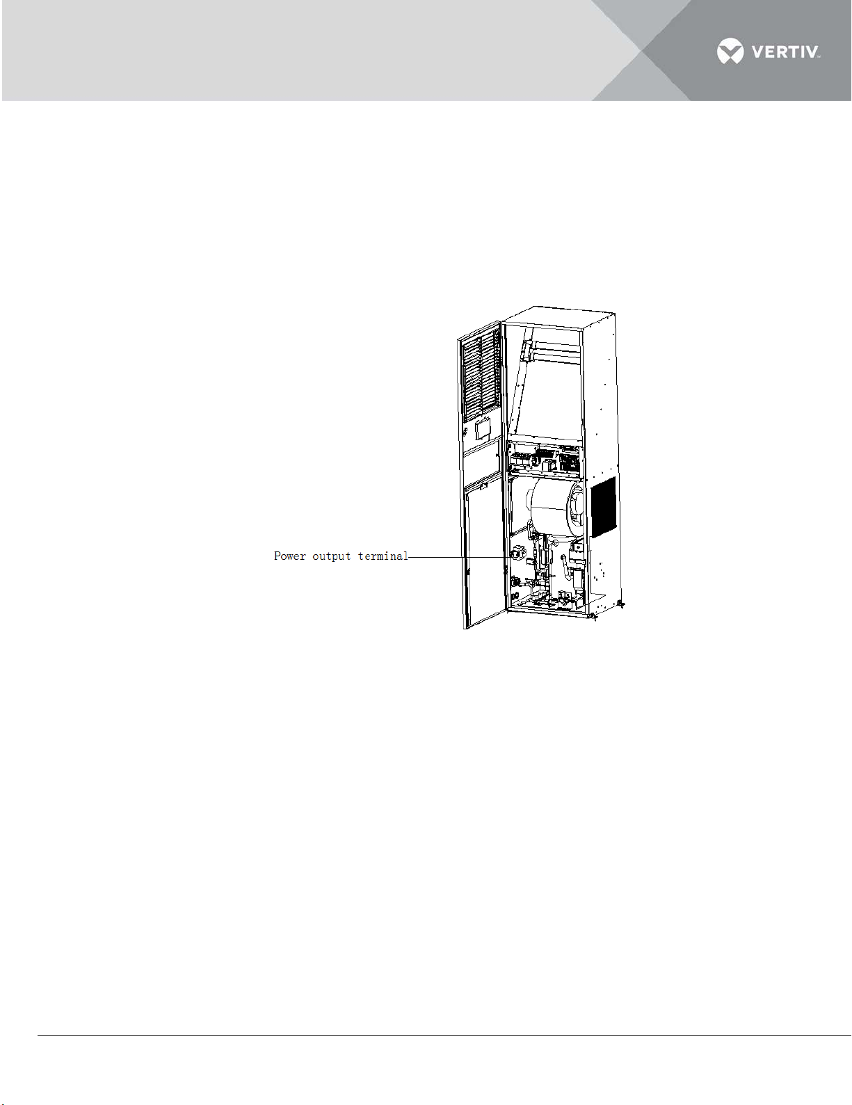
Use the provided inner hexagon wrench to rotate the indoor unit locks, open the front door. At this
point, the power output terminal of the indoor unit is revealed at the left side panel, as shown in
Figure 2-21.
The Figure 2-21shows the Power connection position of indoor unit:
Figure 2-21
Lead the power cable through the cabling hole, connect it to the power output terminal of the indoor
unit, and fasten it with a cable clamp, as shown in Figure 2-22. Connect the other end to the AC
power outside the AC system.
Vertiv | Liebert DM Series Precision Air Conditioner | User Manual 39
Page 51
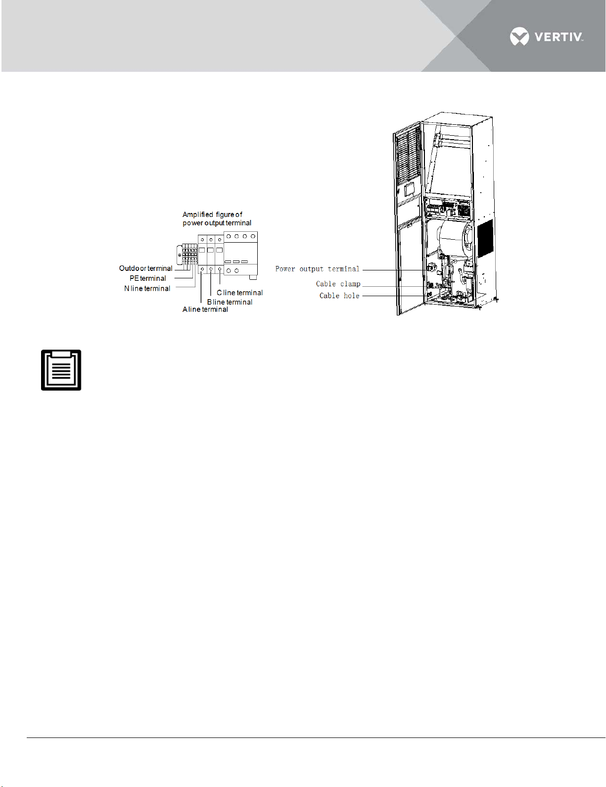
The Figure 2-22 depicts the input and output power wiring of the indoor unit.
Figure 2-22
Use copper cables only and ensure that all connections are solid while wiring
Make sure that the power voltage matches the voltage specified on the unit nameplate.
Install a disconnect switch before the power input of the indoor unit to isolate the unit for
maintenance. Connect the power cable to the disconnect switch and then to the unit.
Cut off the power to the unit before maintenance inside the unit because the unit contains high
voltage
2.5.4 Connecting Power Cable Of Outdoor Unit
The standard length of the outdoor unit power cable is 8m, if a longer cable is required, contact
Vertiv Co. The recommended cable size is not less than 18AWG (0.75mm2).
Connect one end of the outdoor unit power cable to the power output terminal of the indoor unit
(shown in Figure 2-22) and the other end to the power connection terminals of the outdoor unit
(shown in Figure 2-23 and Figure 2-24).
Vertiv | Liebert DM Series Precision Air Conditioner | User Manual 40
Page 52
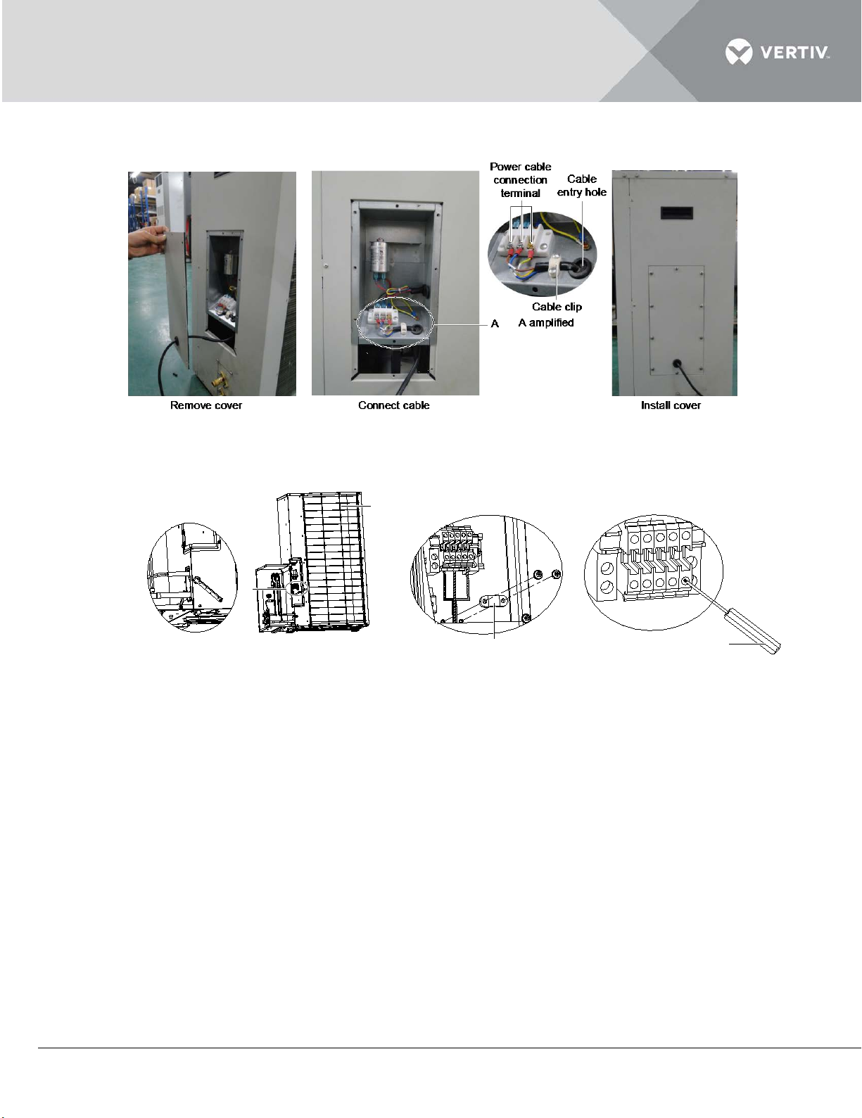
The Figure 2-23 shows the Power connection of standard model outdoor unit
电源线(L+N+PE)
PE N N L L'
A
Power cable (L+N+PE+L')
Back side of
outdoor unit
Cable clip
A: Power connection
Slot screwdriver (3mm)
Terminal designation
Figure 2-23
The Figure 2-24 shows the Power connection of Low-Temp model outdoor unit.
Figure 2-24
2.5.5 Connecting Control Terminals
The control terminals are located on the PCB and terminal block of the electrical control box, as
shown in Figure 2-25.
Vertiv | Liebert DM Series Precision Air Conditioner | User Manual 41
Page 53
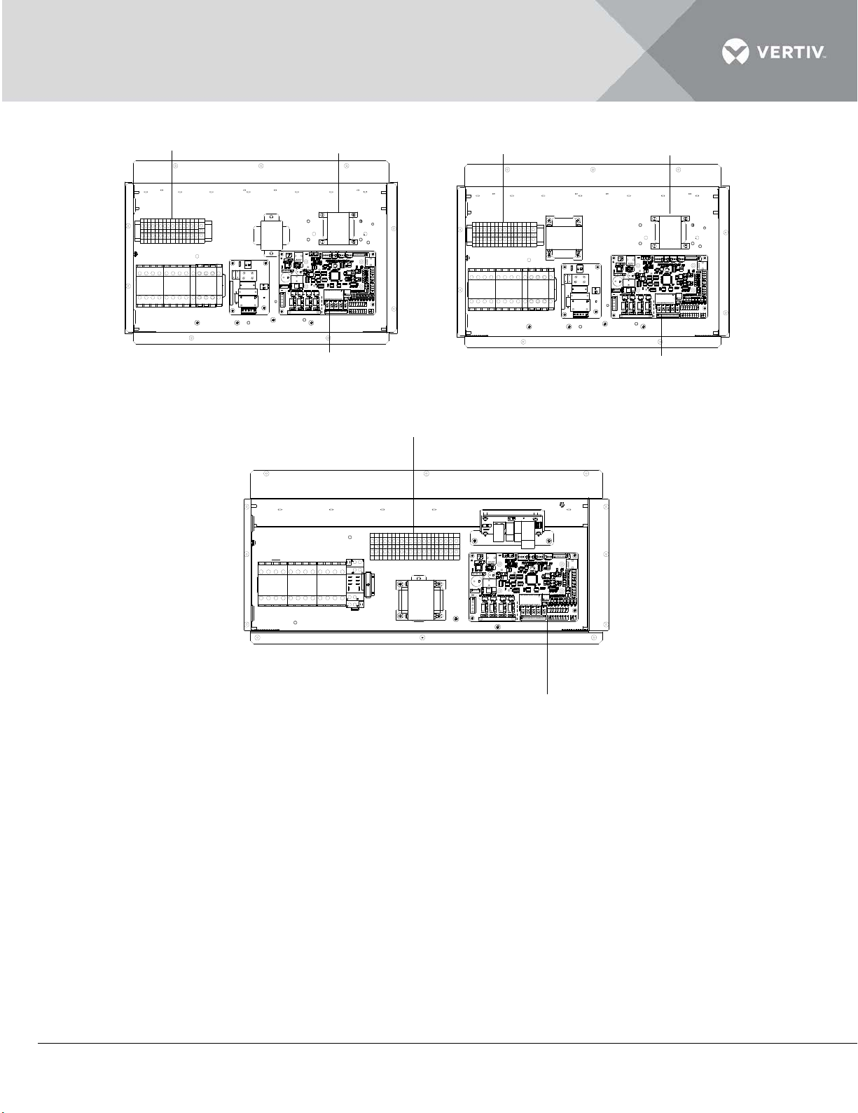
7.5KW single cooling unit 7.5KW humidification unit
control terminals on the terminal block
reactor (EC unit use)
control terminals on the PCB
control terminals on the PCB
control terminals on the terminal block
reactor (EC unit use)
Control terminals on the terminal block
Control terminals on the PCB
12KW cooling unit
Figure 2-25 Control terminal position
Vertiv | Liebert DM Series Precision Air Conditioner | User Manual 42
Page 54
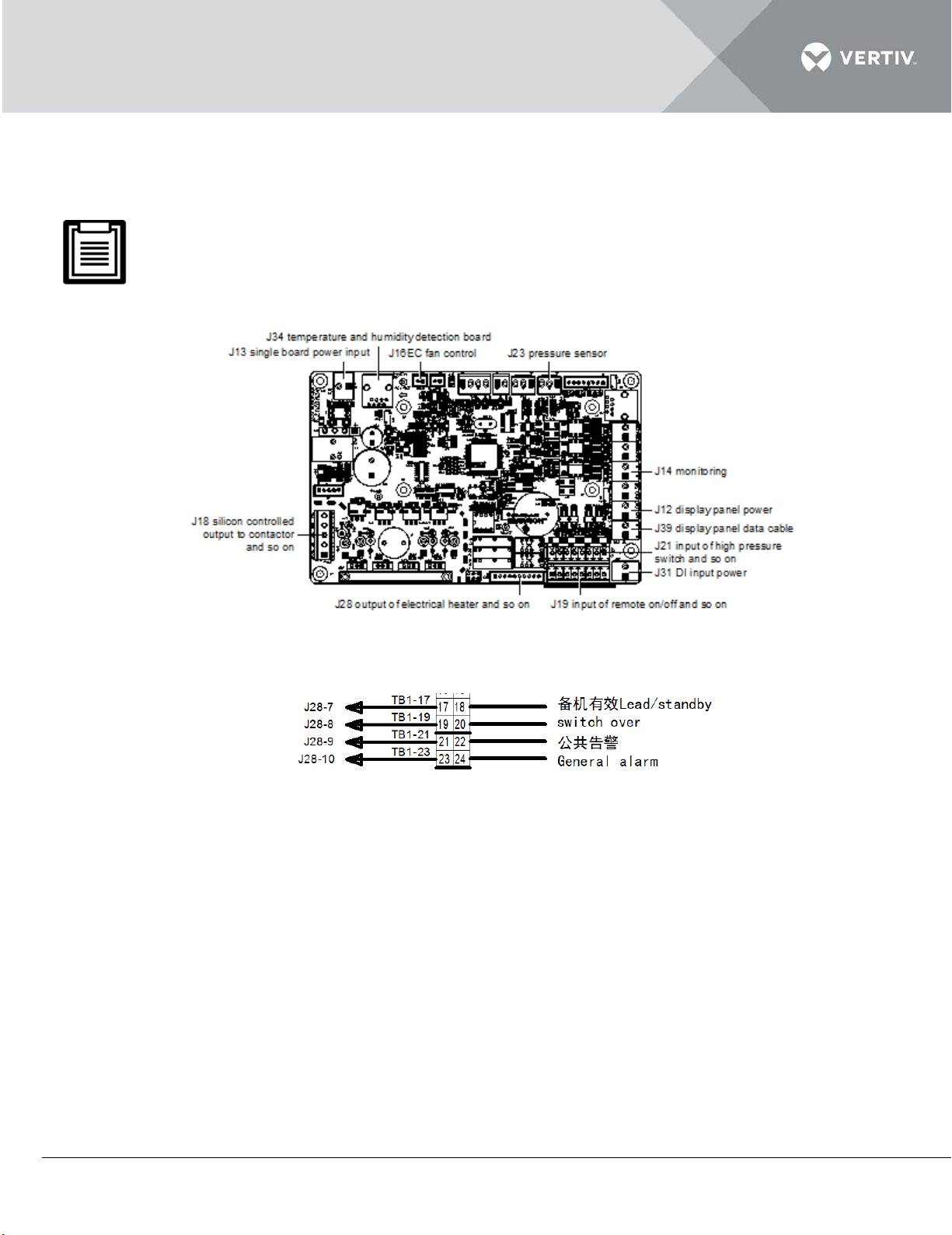
The control terminals on the PCB are shown in Figure 2-26; the control terminals on the terminal
block are shown in Figure 2-27.
Before connecting the control cables, the service personnel must take anti-static measure.
Figure 2-26 Control terminals on the PCB
Figure 2-27 Control terminals on the terminal block
Remote shutdown
The PIN5 and PIN6 of the remote shutdown J19 can be used to remotely control the unit ON/OFF
status, stopping the unit operation depending on the particular time. If the input of remote shutdown
terminal is shorted and the AC unit power is switched on, the AC unit outputs normally. If the terminal
is open, the AC unit will stop outputting. The remote shutdown terminal has been shorted before
delivery. If the control cable of remote shutdown needs to be connected onsite, remove the short
cable and connect the outer controller to the remote shutdown terminal.
Vertiv | Liebert DM Series Precision Air Conditioner | User Manual 43
Page 55

SPD (Customer 1 terminal)
When the PIN1 and PIN2 of the customer 1 terminal (control terminal) J19 are not connected to SPD
signal, they can connect with an alarm signal except for the AC system. Any outer alarm signal with
NO dry contact can be connected to the customer terminal. After the outer alarm signal is connected,
set the corresponding customer alarm information in micro-processing controller. For more details,
refer to Customer Alarm in 3.4.2 Alarm Menu. If there is no alarm signal connected, the input state of
the customer terminal is the same as the settings. If the outer alarm is generated, the input state of
the customer terminal is different from the settings. The AC system will generate an audible alarm
and LCD screen on the micro-processing controller will display the corresponding alarm information.
If a computer using Vertiv Co. host monitoring software is connected, then the alarm will be displayed
on that computer too.
If the power SPD is configured, the PIN1 and PIN2 of the customer 1 terminal J19 has been connected
with alarm signal of power SPD in the factory and the alarm is set to be normally closed (NC).
General alarm terminal
The general alarm relay connected with 19 and 20 on the terminal block (see Figure 6-7) has a set of
NC dry contact, which can be set to normally closed by using the software. When a serious alarm is
generated, the contact is closed. This can be used to send a remote alarm, sending signals to the
building management system or dialing the paging system automatically.
Lead/standby switchover and requirement terminals
The PIN18 and PIN20 of the lead/standby switchover the terminal and the PIN7 and PIN8 of the
requirement terminal J19 (see Figure 2-27) are used to connect two AC units working in master-slave
mode.
Vertiv | Liebert DM Series Precision Air Conditioner | User Manual 44
Page 56
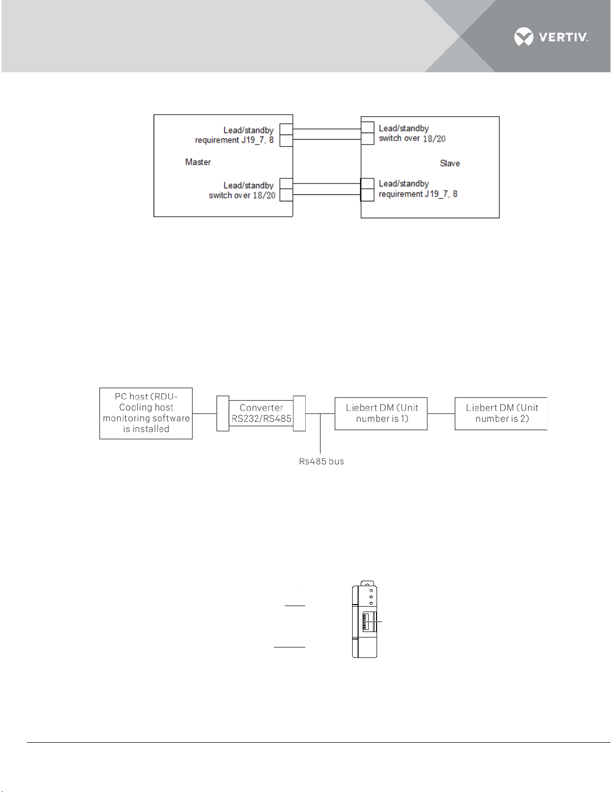
Figure 2-28 shows the Connection in master-slave mode.
ERR
COMM
RUN
DME07MC1A2
Front
Plate
Interface
DIP switch
Figure 2-28
2.5.6 Connecting Monitoring Port Cable
The RS485 port of the Liebert DM indoor unit is located on the J39 terminal on the PCB (see Figure
2-26), uses a twisted-pair communication cable to connect it to the upper machine.
Multiple Liebert DM AC's can recognize simultaneous multi-units monitoring through RS485 bus.
Taking RDU-Cooling host monitoring software developed by Vertiv Co. for example, Figure 2-29
introduces to a networking mode of RS485 bus monitoring two AC units simultaneously.
Figure 2-29 Networking mode monitoring two AC units
2.5.7 Connecting Energy-Saving Card
The Figure 2-20 shows the energy-saving card:
Figure 2-20
Use 4-core shielded cables with a recommended cable diameter not less than 20AWG (0.52 mm2) to
connect the energy-saving card. Make sure that the two ends of the shielded layer and the energy-
Vertiv | Liebert DM Series Precision Air Conditioner | User Manual 45
Page 57
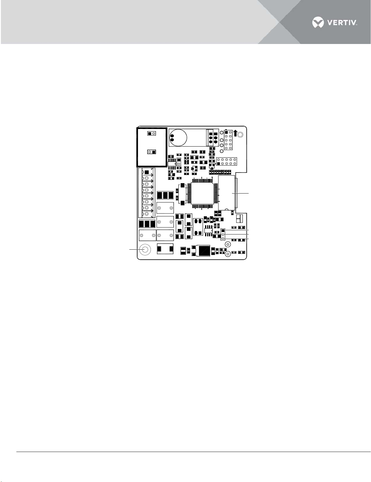
saving card are grounded reliably to increase the anti-interference ability. The grounding cable
J8.3
J8.2
J8.1
ON
+12 V GND CA NHCA NL
CANH
CANL
GND
12V
DIP switch
Earth terminal
should not exceed 10 cm, and the cable size should be above 2 mm2. Make sure that all connections
are tight.
Use the energy-saving card according to the following steps:
Open the front plate of the energy-saving card plastic shell and take out the energy-saving cardboard along with
the card slot inside the plastic shell. The Figure 2-21 shows the energy-saving cardboard.
Figure 2-21
Short the terminals J8.1 and J8.2 in the furthest energy-saving card and short the terminals J8.2 and J8.3 in other
cards.
Ground the cards appropriately.
Put the energy-saving card into the shell along with the card slot and replace the front plate.
Use 4-core shielded cables to connect the Liebert DM control board on the rear portion of the front door of the
indoor unit to 12V, GND, CANH and CANL interfaces of the energy-saving card; then snap the accessory
magnetic buckle on the shield cable close to the control board end.
Use 4-core shielded cables to serially connect 12V, GND, CANH and CANL interfaces of other cards (if more than
one card is used).
Ground the shielded cables appropriately.
Set bits 1 and 2 of the DIP switch to card address and other bits to 0 (ON: 0, OFF: 1).
Fix the energy-saving card in position with the heavy room temperature load with screws or the card slot in the
shell.
Enter Sleep Mod menu to view whether the temperature of the energy-saving card is normal.
Figure 2-22 and Figure 2-23 indicates the connection modes of a single card and multi-cards respectively.
Vertiv | Liebert DM Series Precision Air Conditioner | User Manual 46
Page 58
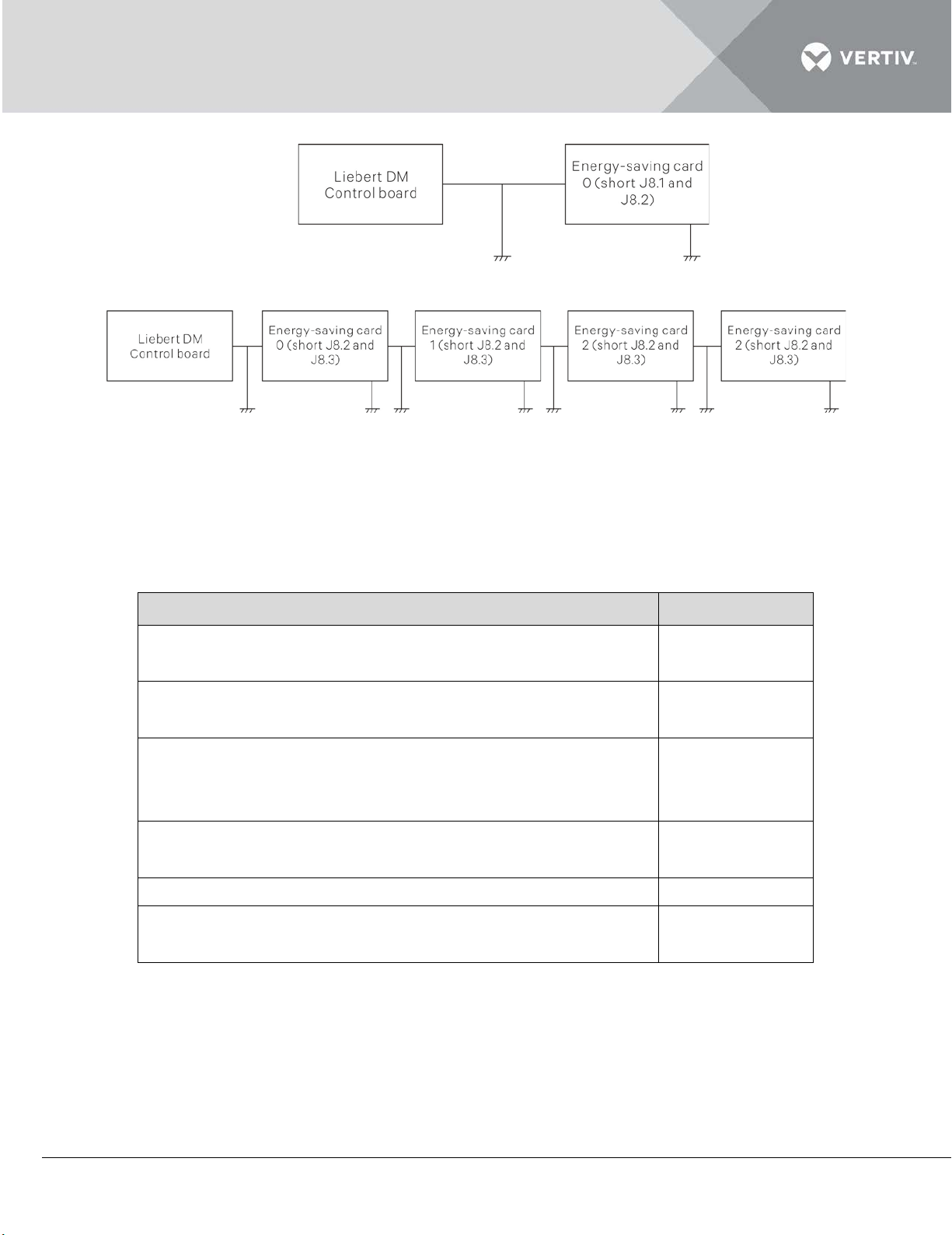
Figure 2-22 Connection of single card
Item
Result
No open-circuit or short-circuit in the electrical connection
The power voltage is the same as the rated voltage on the
The power cables and earth cables connected to the
The circuit breakers or fuses have the proper ratings for
The control connections are completed.
All wiring and connector connections are tight. The fixing
Figure 2-23 Connection of multi-cards
2.5.8 Checklist
Confirm the items in the table under listing 2.10 on completion of Electrical Installation.
Listing 2.10
exists
unit nameplate
disconnect switch, indoor unit and outdoor unit are
connected properly
equipment installed.
bolts are tight.
After confirming the preceding points, start the start-up inspection & function testing.
Vertiv | Liebert DM Series Precision Air Conditioner | User Manual 47
Page 59
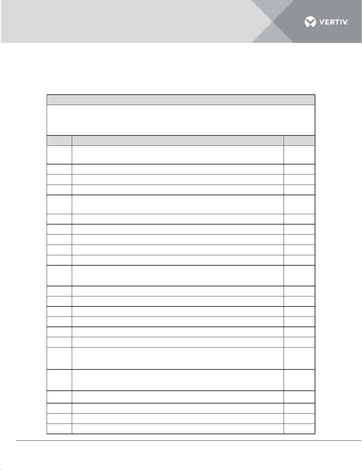
Before starting the System Operations and Commissioning, adhere to the following points as
Pre-Commissioning Checklist
Name of Customer:
SL
Indoor Unit positioning & Power cabling, CU piping, GI piping
Remar
1
Indoor units are properly spaced with maintenance point view,
minimum gap of 6" is maintained on back side & in between the
2
Proper leveling of Liebert DM indoor stand with proper grouting
3 Drip tray installed properly with silicon sealant applied on the
4 Units are installed properly with rubber pads in between the unit
5
Proper earthing is provided in the mains power supply as well as
body earthing for PAC unit
6
Power cable is provided with proper sizing of cable to suit the full
7
Power supply is connected to the mains switch with proper lugs &
8
Mains power cable is not routed with low voltage cables
9 Soap leak test on brazing joints & also in Cu piping
10
Pressure holding time
11
Quality of copper piping laying, equidistance in-between two
12
Initial U trap provided near the indoor unit
13
U traps provided after every 7 RMT in vertical length (if require)
14
Inverted U trap provided near the outdoor unit
15
Copper pipe with insulation are tagged properly to indicate the
16
Proper supporting for refrigerant piping is done
17
Copper pipes are painted with proper color code
18
Additional piping kit installed in case vertical distance between
19
Cable trays are used of proper gauges & quality. Ensure supports
20
Dressing & proper routing condenser cable
21
Condenser cable & copper pipes are tagged with unit No & circuit
22
Sufficient fresh air for condenser
23
No hot air short cycling for condenser
mentioned in the checklist:
Listing 2.11
Site Location:
Details:
pipes, Quality of copper piping laying, equidistance in-between
indoor to outdoor is
provided at equal distance to avoid the sag on cable tray
Vertiv | Liebert DM Series Precision Air Conditioner | User Manual 48
Page 60
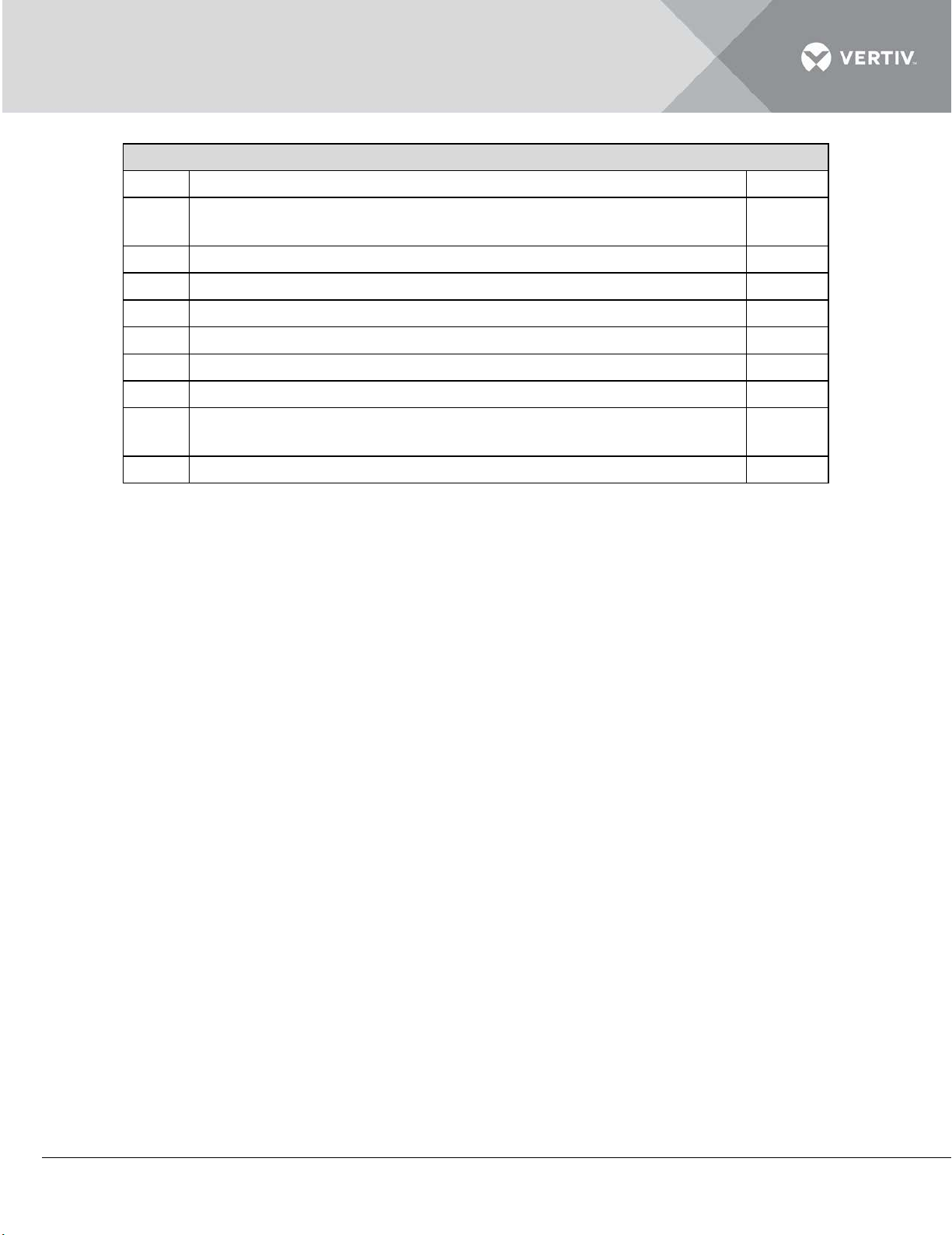
Pre-Commissioning Checklist
24
Proper earthing is done for condenser
25
Proper supporting given for the condenser in case condensers
are mounted one above
26
Concrete pedestal are provided for the condenser stand
27
Rubber pads are provided in between the condenser & stands
28
Condenser coils & Copper pipes U bends are painted with
29
Proper slope is maintained for drain pipes
30
U traps is provided at end drain pipe
31
Isolating valve provided on inlet of humidifier piping
32
Fresh water head pressure maintained of 21 - 100 PSI & with PPM
level of 80 to 300 (optional)
33
Ensure no leakage in the humidifier & drain piping before
Vertiv | Liebert DM Series Precision Air Conditioner | User Manual 49
Page 61

PART III
SYSTEM OPERATION & GEN
MAINTENANCE
ERAL
Vertiv | Liebert DM Series Precision Air Conditioner | User Manual 50
Page 62
3 System Operation
Item
Inspection requirements
Panel
No damage, well insulated and clean
Filter
Installed in place and reliably, no damage and clean
Measure and record the voltage before the system is powered
The outdoor unit is installed reasonably; the pipes are
Fan
No obstruction material in inlet and outlet area
Humidifier (if
Water supply pipe and drain pipe are connected; water level
Heater (if
Power SPD (if
Controller
The wiring connections are tight
This chapter introduces the system operation, start-up inspection, function testing, general
maintenance and preliminary troubleshooting of the Liebert DM AC.
3.1 Start-Up Inspection
Prior to starting up the system; inspection of the state of the parts is required. The requirements for
start-up inspection are mentioned in the following table within listing 3.1
Listing 3.1
Power supply
Outdoor unit
applicable)
applicable)
applicable)
on. Power cables are connected reliably
supported and sloped down properly; the trap is installed in a
correct position
sensor is secured correctly
Heating components are secured reliably
The module is secured reliably
Vertiv | Liebert DM Series Precision Air Conditioner | User Manual 51
Page 63
After inspecting and confirming the preceding items, power on the AC unit. The inspection
Item
Inspection requirements
The rotation direction is correct; record the rated full load
Heater (if
The rotation direction is correct; record the rated full load
Record the user setpoints, return air temperature, suction
requirements after starting-up are mentioned in the following table within listing 3.2.
Listing 3.2
Fan
current and actual current of the fan motor
Record the heater current
applicable)
Outdoor fan
current and actual current of the fan motor
Others
pressure, discharge pressure, compressor current and discharge
air temperature
3.2 Micro-Processing Controller
The Micro-processing controller for Liebert DM AC comes packed with potential features that help
monitor and manage the AC unit.
3.2.1 Features
The micro-processing controller has the following features:
Adopt menu operation. It can monitor and display the operation status of precise cooling AC unit to keep the
environment within a setting range.
Adopt a 128 × 64 dot LCD screen with white backlight. The user interface is easy-to-use.
Provide three-level password protection to prevent unauthorized operation effectively.
Provide the functions, including self-recovery upon power failure, high-voltage & low-voltage protection, phase
loss protection and automatic phase-sequence switching upon anti-phase.
Accurately know the running time of important components through menu operation.
The expert-level fault diagnoses system can automatically display the current fault information to facilitate
maintenance personnel in equipment maintenance.
Store up to 200 historical alarm records.
Configured with an RS485 port.
3.2.2 Appearance
Vertiv | Liebert DM Series Precision Air Conditioner | User Manual 52
Page 64
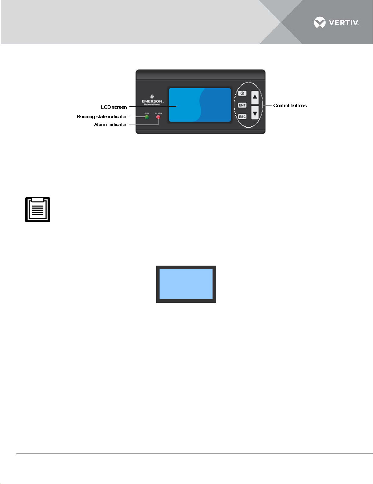
The micro-processing controller panel is depicted in Figure 3-1.
21 C HEAT SIGL
50% HUM RUN
Hi Hum 4
2012/01/01 00:00
°
Figure 3-1
3.2.3 LCD Screen
The LCD screen displays English menus with white backlight. When the system is operating normally,
it displays the current temperature & humidity (humidity display is optional).
Only the unit configured with a humidifier can display humidity; refer to section Select Options in 3.4.5
System Menu for more details.
It also displays unit output status (cooling, heating, dehumidifying and humidifying), unit mode (single,
lead, standby), unit operation status (running, standby, locked), alarm information and current date &
time, as depicted in Figure 3-2.
Figure 3-2
A detailed operating status of a specific component and alarm information is available on the Main
Menu screen. The selected menu item will be highlighted while browsing. The digit to be changed will
be highlighted while the user is changing the settings.
3.2.4 Control Buttons
The micro-processing controller provides five control buttons, as depicted in Figure 3-3
Vertiv | Liebert DM Series Precision Air Conditioner | User Manual 53
Page 65
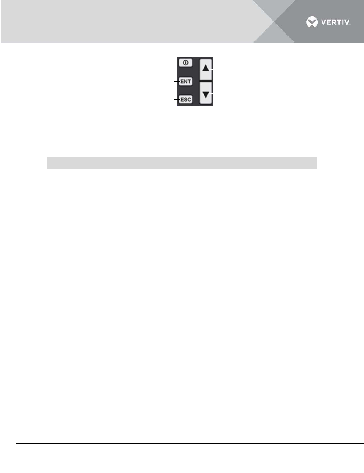
Figure 3-3
Control button
Function descriptions
ON/OFF button
Press this button for 3s to turn on or off the unit
Enter button
Enter the selected menu screen. Validate the parameter setting
Exit the current menu and return to the Normal screen or
Move the cursor up or increase the parameter value. For a toggle
Move the cursor down or decrease the parameter value. For a
ON/OFF button
Enter button
Esc button
Down button
Up button
The functions of the control buttons are described in Table within Listing 3.3
Listing 3.3
(ENT)
value
Esc button
previous menu screen. Abort parameter change; silence the
(ESC)
audible alarm
Up button
selection: scroll through the options. For a multi-screen menu:
scroll up the screen
Down button
toggle selection: scroll through the options. For a multi-screen
menu: scroll down the screen
3.2.5 Control Buttons Operation Example
Example 1: Inputting password to enter the Main Menu
This section depicts the process where the password is entered to access the Main Menu. After the
unit is powered on, the unit starts up.
Following are the step-by-step instructions that can need to be adhered and implemented to enter
the Main menu.
Press the Enter button to enter the Password screen.
Next, press the Enter button again to highlight the input data field on the Password screen.
Press the Up and Down button to change the current password number.
Press the Enter button to confirm the password following which the Main Menu screen is populated on the
controller screen.
Vertiv | Liebert DM Series Precision Air Conditioner | User Manual 54
Page 66
Example 2: Changing parameters
Connecting…
通讯中,请稍后
This section depicts the process of changing parameters. In this example, Hi Temp in Alarm Output
screen is used for illustration purposes. Following are the step-by-step instructions for changing
parameters:
Press the Up or Down button to move the cursor on the Alarm Menu menu in the Main Menu screen.
Press the Enter button to enter the Alarm Menu menu.
Press the Up or Down button to move the cursor on Alarm Setting in the Alarm Menu screen.
Press the Enter button to enter the Alarm Setting screen.
Press the Up or Down button to move the cursor on Hi-Temp.
Press the Enter button to highlight the parameter field of Hi-Temp.
Press the Up or Down button to select the parameter option.
After selecting, press the Enter button to confirm. The parameter will take effect.
Press the Esc button to return to the previous menu screen.
On changing the parameters, the Enter button needs to be pressed in order to confirm it. If the Enter
button is not pressed, it means that the confirmation of the parameter change has not taken place.
Therefore, on non-confirmation, the original value of the Hi-Temp will be retained.
3.2.6 ON Screen
After the AC unit is powered on, the LCD screen will display the ON screen, as shown in Figure 3-4.
Figure 3-4
3.2.7 Language Screen
After the AC unit is powered on, the language screen will be displayed after 10 seconds (default) for
choosing the language or through pressing the Enter button directly, as shown in Figure 3-5.
Vertiv | Liebert DM Series Precision Air Conditioner | User Manual 55
Page 67
Figure 3-5
Choose Language:
请选择语言:
中文(Chinese)
英文(English)
21 C HEAT SIGL
50% HUM RUN
No alarm 0
2012/01/01 00:00
°
Password: 1***
3.2.8 Normal Screen
After the AC unit is powered on, the Normal screen will be displayed after 20 seconds (default) for
heat startup delay or by pressing the Enter button directly, as shown in Figure 3-6. The Normal
screen displays the following information: the current temperature and humidity, unit operation state
(cooling, heating, dehumidifying, humidifying), unit mode (single, lead, standby), unit operation status
(running, standby, locked, off, sleep), alarm information and current date & time.
Figure 3-6
3.2.9 Password Screen
Press the Enter button on the Normal screen following which the Password screen appears as
depicted in Figure 3-7.
Figure 3-7
Vertiv | Liebert DM Series Precision Air Conditioner | User Manual 56
Page 68
The table in Listing 3.4 depicts the 3 levels of passwords for accessing the menu. The detailed
Password
level
User
Initial
password
Remark
Browse all menu information. Only set
Maintenance
Factory
descriptions are mentioned in Table within Listing 3.4
Listing 3.4
Level 1 General operator 0001
temperature and humidity setpoints
(see Figure 3-13) and cannot change
any values and settings
Level 2
- Set all parameters
personnel
Level 3
- -
technician
For detailed operation on entering the password, refer to section 3.2.5 Operation Example.
On entering an incorrect password, the users cannot change the settings; however, they can view the
menu. To go back to the Normal screen, press the Esc button and then click on the Enter button to get
access to the Password interface again. If the users do not enter a password and press the Enter button,
then similar to the incorrect password example, the users can view the menu settings but cannot change
any parameters.
3.3 Function Testing
The AC unit carries hazardous voltage. Cut off the power before testing the equipment. The test should
be done under the guidance of Vertiv Co.'s professional maintenance personnel or trained service
personnel.
3.3.1 Cooling
The temperature set point should be adjusted based on the Set Points (Refer section 3.4.3) up to 5°C
(10°F) lower than the indoor temperature. Then, the control system should trigger the cooling
demand and the compressor starts working. At least after 3 minutes of cooling, adjust the
temperature set point to 5°C (10°F) higher than the indoor temperature. If the compressor stops
working, it means that the cooling function is normal.
Vertiv | Liebert DM Series Precision Air Conditioner | User Manual 57
Page 69
Restore the temperature set point to the default or the original value after the test
3.3.2 Heating
The temperature set point should be adjusted based on the Set Points (Refer section 3.4.3) up to
5°C (10°F) higher than the indoor temperature. Then the control system should trigger the heating
demand and the heater starts working. Adjust the temperature set point to 5°C (10°F) lower than the
indoor temperature. If the heater stops working, it signifies that the heating function is normal.
Restore the temperature set point to the default or the original value after the test.
3.3.3 Humidifying
The humidity set point should be adjusted based on the Set Points (Refer section 3.4.3) to 10% higher
than the indoor relative humidity. Then, the control system should trigger the humidifying demand
and the humidifier starts working. Adjust the humidity set point to 10% lower than the indoor relative
humidity. If the humidifier stops working, it signifies that the humidifying function is normal.
Restore the humidity set point to the default or the original value after the test.
3.3.4 Dehumidifying
The humidity set point should be adjusted based on the Set Points (Refer section 3.4.3) to 10% lower
than the indoor relative humidity. Then, the control system should trigger the dehumidification
demand and the fan starts running at a low speed. Adjust the humidity set point to 10% higher than
the indoor relative humidity. If the fan automatically starts running at a higher speed, it signifies that
the dehumidification function is normal. Note that during the testing process, if the indoor
temperature is 3°C higher than the temperature set point, the system may enter a forced cooling
mode and the dehumidification demand will not be responded.
Restore the humidity set point to the default or the original value after the test
3.3.5 Checking Refrigerant Charge Capacity of Low-Temp Outdoor
The Low-Temp outdoor unit has been charged with refrigerant before delivery.
Vertiv | Liebert DM Series Precision Air Conditioner | User Manual 58
Page 70
The refrigerant charge capacity should be proper after powering on; it can be verified using the
<Alarm Menu>
<Set Points>
<System Status>
<System Menu>
<Help Menu>
<Display Setting>
following method:
When the high pressure is not lower than 240psig (16.5bar), the liquid level of the refrigerant will
reach the 1/2 point of the tank sight glass. When the ambient temperature is low and the high
pressure cannot meet the requirement, the user can block the part of the upside and downside of the
air intake uniformly to obtain required pressure.
If the liquid level cannot meet the requirement, discharge or refill the refrigerant for a proper liquid
level length. Reclaim the discharged refrigerant according to correlative requirement.
3.4 Micro-Processing Controller Menu Options
3.4.1 Main Menu
On entering the correct credentials for the password and confirming it, the users will gain access to
the Main Menu screen. For more information, refer to the section Appendix - 2 -Menu Structure.
Enter the password in the Password screen and confirm following which the Main Menu screen will
appear, as shown in Figure 3-8.
Remember that the users can change the settings of most of the parameters; however, there are
some parameters that cannot be modified or altered.
For detailed setting procedures, refer to section 3.2.5 Operation Example. For the setting ranges of
the menu items that can be set, refer to Appendix - 3 Parameter Setting Table.
Figure 3-8
Vertiv | Liebert DM Series Precision Air Conditioner | User Manual 59
Page 71
The table under Listing 3.5 describes the different menu items on the Main Menu screen
Listing 3.5
Menu item Descriptions
Alarm Menu
Set alarm parameters; browse alarm historical records and alarm
status records
Set Points Set temperature & humidity setpoints and their sensitivities
System Status Browse ambient temperature & humidity, system output status
and system running records; browse and set system time
Set system parameters and system options; calibrate sensor;
System Menu
change password; output system diagnoses; restore factory
parameters; configure optional function
Browse factory information, product information and maintenance
Help Menu
information
Display Setting Adjust the screen contrast
3.4.2 Alarm Menu
On the Main Menu screen, the users must click on Alarm Menu to gain access to the Alarm Menu
interface. Press the Up and Down button to scroll up or down the menu items.
Figure 3-8 depicts the Alarm Menu screen:
<Alarm Status>
<Alarm History>
<Alarm Setting>
Figure 3-9
Vertiv | Liebert DM Series Precision Air Conditioner | User Manual 60
Page 72
Alarm Status
The Alarm Status menu is used to monitor the present alarm status of the AC unit and prompt No
Alarm or detailed alarm status information.
The detailed alarm status information includes XX/YY, alarm type and alarm start time, as shown in
Figure 3-10. XX is the serial number of alarm status record and YY is the total number of alarm status
record.
Current: 1/8
Hi Temp
2012/01/01 00 :00
Figure 3-10
The latest alarm SN is the biggest number. Press the Up or Down button to scroll through the alarm
status records if more than one alarm is activated.
The alarm status records will be automatically cleared upon system power-off.
Alarm History
The Alarm History menu is used to view the historical alarm records of the AC unit, including XX/YY,
alarm type, alarm start time and alarm end time (if the alarm is not ended, the screen displays Not
ed Yet), as shown in Figure 3-11. XX is the screen of the historical alarm record and YY is the total
End
n
umber of the historical alarm records.
History: 1/4
Hi Temp
2012/01/01 00:00
2012/01/01 01:22
Figure 3-11
Press the Up or Down button to scroll through the historical alarm records if more than one alarm is
activated.
Up to 200 historical alarm records can be stored. They will not be cleared upon system power-off.
Vertiv | Liebert DM Series Precision Air Conditioner | User Manual 61
Page 73
Alarm Setting
The Alarm Setting settings will not be lost when the power fails. The Alarm Setting screen is
depicted in Figure 3-12. For detailed setting range, refer to Appendix - 3 Parameter Setting Table.
It is not recommended to change the defaults. If the change is necessary, change them under the
guidance of the trained professionals.
Hi Temp 30.0 C
Lo Temp 18.0 C
Hi Hum 60.0%
Lo Hum 40.0%
Hum Fail EN
High Water
Temp Snsr
HP LOCK EN
Phase rev EN
Customer 1 EN
T/ H Card EN
Air Loss EN
°
°
EN
EN
AirflowDT 15.0 °C
Hi Press EN
Lo Press EN
Dschg Temp EN
LP LOCK EN
Dschg LOCK EN
Water UF EN
Overvoltage EN
Customer 2 EN
Press Snsr EN
Hum Snsr EN
AirLoss Snsr EN
F
igure 3-12
Hi Temp EN
Lo Temp EN
Hi Hum EN
Lo Hum EN
Power OV EN
Undervoltage EN
Freq offset EN
Phase Loss EN
Customer 1 NC
Customer 2 NC
General Alm NO
ClearAlmHis N
Vertiv | Liebert DM Series Precision Air Conditioner | User Manual 62
Page 74
Listing 3.5
Settings
Alarm history
record
Alarm status
record
Audible alarm
Alarm prompt
EN
Yes
Yes
Yes
Yes
DIS
Yes
Yes
No
No
MSG
No
No
No
No
Temp Set 24.0 C
Temp Band 3.0 C
Hum Set 50.0%
Hum Band 5.0%
°
°
The alarms Hi Press, Lo Press and Hi-Temp are serious fault alarms. So they cannot be set to OFF, but
can only be set to EN and DIS.
Customer Alarm
The AC unit is provided with two customer alarms, including customer 1 and customer 2; it
corresponds to PIN1, 2 of the control terminals J19 and PIN5, 6 of J19 respectively.
The customer alarm can be set to ‘NO’ or ‘NC’. The user can set them according to the actual alarm
signal of the control terminals. If the power SPD is selected, the customer 1 alarm terminal has been
connected with power SPD alarm signal before delivery and the customer 1 has been set to ‘NC’.
3.4.3 Set Points
On the Main Menu screen, the user can select the Set Points option to gain access to the Set points
menu as depicted in Figure 3-13.
The Set Points settings will not be lost when the power fails. For detailed setting ranges, refer to
Appendix - 3 Parameter Setting Table.
Figure 3-13
3.4.4 System Status
On the Main Menu screen, the user can select the System Status option to gain access to the System
Status menu as depicted in Figure 3-14.
Vertiv | Liebert DM Series Precision Air Conditioner | User Manual 63
Page 75
Figure 3-14
<Analog>
<Time/Date>
<I/O Status>
<Run Time>
<On/Off Record>
Rtn Temp 24.6 C
Rtn Hum 67.8%
NTC0Temp 25.0 C
Temp Cal 0.0 C
°
°
°
Hum Cal 0.0%
NTC0 Cal 0.0 C
Press1: 15.6Bar
Press2: 0.0Bar
°
Phase A: 220.0V
Phase B: 220.0V
Phase C: 220.0V
Pwr Freq: 0.0Hz
Sw Code 0
Year 2012
Month 1
Day 1
Hour 0
Min 0
Second 0
Analog
The Analog menu displays the indoor temperature & humidity, 3-ph voltage & frequency and
condenser pressure with a decimal in real time, as depicted in
Figure 3-15.
Figure 3-15
Time/Date
The Time/Date screen displays the current time and date of the system in the Year/Month/Date
format and Hour/Minute/Second, as depicted in Figure 3-16.
Figure 3-16
Vertiv | Liebert DM Series Precision Air Conditioner | User Manual 64
Page 76
I/O Status
Evap Fan OFF
Compressor OFF
Heater OFF
Humidifier OFF
Low FanSpeed
Cond Fan OFF
General Alm
OFF
OFF
Fill OFF
EC Output 0.0V
Manual EN N
Hi Press OPEN
Stdby En OFF
Dschg Temp OPEN
Water UF OPEN
Customer 1 OPEN
Lo Press OPEN
Customer 2 OPEN
StdbyReq OPEN
OEM HumFail OPEN
High Water OPEN
Evap Fan 0h
Compressor 0h
Heater 0h
Humidifier 0h
Cond Fan 0h
<Evap Fan>
<Compressor>
<Heater>
<Humidifier>
Evap Fan 1/4
2012/01/01 00:00
2012/01/01 00:00
The I/O Status screen is depicted in Figure 3-17. The user can browse the current input and output
status of the unit on the screen. If Manual Run Enab is set to ‘YES’, the output can be controlled
manually. If the manual output is inner fan output then the rest of the outputs will be closed; if the
manual output is electrical heater output, the inner fans will be started up simultaneously and the rest
of the outputs will be closed. The system will exit the manual mode in an hour automatically if the
user does not exit the manual mode.
Figure 3-17
Run Time
The user can browse the current operation hours of the equipment on the screen. The Run Time
screen is depicted in Figure 5-18.
Figure 3-18
Users can view the start and stop records of important components using this facility. Select the On/Off Record item on the
Run Records screen following to access its menu.
Figure 3-19 depicts the On/Off Record screen:
Figure 3-19
Vertiv | Liebert DM Series Precision Air Conditioner | User Manual 65
Page 77
3.4.5 System Menu
<System Setup>
<Outdoor Unit>
<Optional Func>
<Set Password>
Protocol YDN23
Unit Addr 1
Baud Rate 19200
Overvoltage 15%
Undervoltage 15%
Fq Offset 3Hz
Pwr Freq 60Hz
EvapFanStart 10s
EvapFanStop 30s
CP MinOn 180s
CP MinOff 180s
Cold Start 180s
Hum Ctrl REL
Temp Compens N
Fan Type AC
EC STD 75%
Factory Reset
Run Interval 10h
EC Dehum 65%
Hum Time 30s
Fill Time 8Min
Fill Rate 150%
Prefill Time 7s
On the Main Menu screen, the user can select the System Menu option to gain access to the System
Menu as depicted in Figure 3-20
Figure 3-20
System Setup
The System Setup settings will not be lost in case of the power failure. The menu screen is depicted
in Figure 3-21. For detailed setting ranges, refer to Appendix - 3 Parameter Setting Table.
Figure 3-21
Factory Reset
Use Up or Down button to move the cursor to Reset Factory in the Setup System menu and press
the Enter button. Use Up or Down button to set it to YES or No and press the Enter button to
validate the setting. If Yes is selected, all system set points will be restored to the factoryrecommended values, but the operation time and history alarm records will not be cleared.
As the Factory Reset will clear all set points configured by the user and the AC unit will be turned off,
always be cautious to use it.
Vertiv | Liebert DM Series Precision Air Conditioner | User Manual 66
Page 78
Outdoor Unit
Min. Volt 30%
Max. Volt 100%
Output Volt 95%
Press Bd 5.0Bar
Start P 13.0Bar
Heater Qty 0
Hum Type IF
Economy Mode OFF
Start at 22:00
End at 7:00
Band Zoom 0.0 C
T/H Card Qty 4
Sleep at 27.0 C
°
°
1#: 0.0 C
2#: 0.0 C
3#: 0.0 C
4#: 0.0 C
°
°
°
°
System Mode SIGL
Switch Mode STDB
Rotate Freq 1d
Rotate at 12:00
Level 1 ****
Level 2 ****
The Outdoor Unit menu screen is depicted in Figure 3-22.
Figure 3-22
Optional Function
The Optional Func will not be lost in case of the power failure. The menu screen is depicted in Figure
3-23. For detailed setting range, refer to Appendix 3 - Parameter Setting Table.
Figure 3-23
Only when the energy-saving card No. is not zero, the Sleep Mod can start. Only the Liebert DM AC
equipped with more than one energy-saving card (dedicated) can enter the Sleep Mod. The lead unit
and standby unit cannot use the same card.
When a lead unit and a standby unit are available, the user must set one of them as the lead unit. If the
user sets both of them as the standby units, they cannot work normally.
Change Password
The Change Password settings will not be affected in case of power failure. The menu screen is
depicted in Figure 3-24.
Figure 3-24
3.4.6 Help Menu
Vertiv | Liebert DM Series Precision Air Conditioner | User Manual 67
Page 79
On the Main Menu screen, the user can select the Help Menu option to gain access to the Help Menu
<Version Info>
<En Activation>
Disp Bd: ACM02D1
Version: 1.01.000.00
Ctrl Bd: ACM02U2
Ver: 1.01.000.00
Contrast 48
Language English
screen as depicted in Figure 3-25. The En Activation is not disclosed to the users.
Figure 3-25
Version Info
The Version Info menu is used to browse the version Info, as depicted in Figure 3-26.
Figure 3-26
3.4.7 Display Set
On the Main Menu screen, the user can select the Display Set option to gain access to the Display
Set screen as depicted in Figure 3-27.
Figure 3-27
Vertiv | Liebert DM Series Precision Air Conditioner | User Manual 68
Page 80
4 General Maintenance
This section deals with the system operation and maintenance of the Liebert DM AC. In this section,
the following points or items will be discussed to help users get to grips with the routine inspections
and checks from a user-perspective. It includes the maintenance of electrical parts and connections,
indoor unit, outdoor unit and inspection checklist. It also discusses the basic troubleshooting which
can be understood from a user perspective.
Prior to operation and maintenance, lethal voltage may be present in the equipment which can be
fatal. All notes, warnings, and cautionary warnings marked on the equipment as well as the ones
mentioned in the manual must be considered, otherwise, it may lead to injury and fatality.
Disconnect local and remote power supplies before operating or working with the equipment.
Qualified and Professional Maintenance personnel are the ones supposed to operate and handle the
equipment. Careful and cautionary measures are conveyed to the professional personnel and therefore,
only those personnel may perform maintenance on these machines.
Check the label of the components of the unit as well as the manual to ensure all aspects are taken
into account before operation and maintenance.
Follow all the local codes, protocols, and regulations prior to maintenance.
Read all the instructions to verify that all the parts are included and check the
nameplate to ensure that the voltage matches the available utility power
Vertiv | Liebert DM Series Precision Air Conditioner | User Manual 69
Page 81

4.1 Electric Inspection
Visual checks need to be carried out to check the correctness of electrical connections and circuit
corrosion of the control board, power detection board, filter board, display board and THS board on a
semi-annual basis.
The micro-processing controller has five circuit boards which jointly complete the system fault
detection, input and output.
Inspect the boards one by one according to the following procedures:
Conduct the electrical insulation test on the system to find out bad electrical connections and contacts.
Disconnect all the fuses and MCBs of the control part during the test as the high voltage from the insulation test
could damage the components.
Check the contactors prior to powering on the unit to ensure that the contactors can hold and un-hold freely.
Clean the electrical and control components off dust with a brush or dry compressed air.
Check the closing of contactors for arcs or signs of burning. Replace the contactors, if required.
Fasten all the electrical connection terminals.
Check that the sockets and plugs are in good condition. Replace the contactors, if required.
Check if the power cables are damaged; get them replaced by a qualified/certified electrician.
All circuit boards are not hot-pluggable. A Large instant current will be produced if the board is plugged
or unplugged with powering on and it may lead to unrepairable damage to the circuit. The control board
can only be maintained after the micro-processing controller is powered off.
4.2 Indoor Unit Maintenance
4.2.1 Filter
The filter is a consumable part. Its replacement interval is directly related to the cleanliness status of
the equipment room. In order to maintain efficient operation, the filter should be checked monthly
and replaced or washed as recommended. The filters of the indoor unit are installed on the front door
and side panel.
Vertiv | Liebert DM Series Precision Air Conditioner | User Manual 70
Page 82
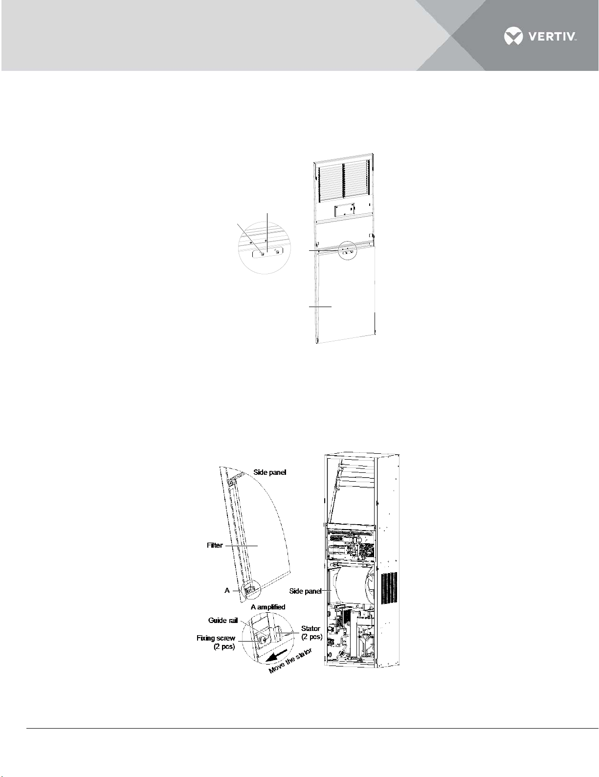
To remove the Filter on the front door:
Filter
A
A amplified
Stator
Fixing screw
(2 pcs)
Front door
Unscrew the fixing screws on the filter stator;
Remove the filter stator to take out the filter on the front door, as depicted in Figure 4-1.
Figure 4-1
Filter on the side panel:
Unscrew (do not remove) the fixing screws on the filter stator and move the stator along the guide rail.
Take out the filter on the side panel, as depicted in Figure 4-2.
Figure 4-2
Vertiv | Liebert DM Series Precision Air Conditioner | User Manual 71
Page 83

4.2.2 Fan
The monthly inspection items of the fan kit include:
motor operation status
impeller status
fan kit fixation
clearance between fan and impeller.
Monthly inspection of motor bearing and impeller should be carried out and replace it if any damage
has occurred.
Check whether the impeller is tightly mounted on the rotor of the motor and does not rub against its
neighboring metal components during rotation.
Since the fan kit operates continuously 24 hours a day, any unusual airflow obstruction must be
cleared in time to avoid the damage to the cooling system and other system components caused by
reduced air volume.
4.2.3 Drain Pipe
For normal operation of the drain pipe, inspection of the water tray should be carried out periodically.
Ensure that there are no foreign particles or any leakage present in the drain pipe.
4.2.4 Heater
If the optional heater is used, it should be maintained periodically. Ensure that there is no dust or any
foreign particles collected on its surface; the heater is fixed appropriately and the cable connections.
The heater elements will heat continuously in the normal station. Inspection of the heater should be
carried out bi-annually for its normal operation.
If in case the heater needs to be replaced, please contact the Vertiv Co. maintenance personnel.
The heater cable must be leaded through the thimble socket, and then connected to the heater.
4.2.5 Humidifier
The humidifier kit consists of infrared lamp, water supply solenoid valve, water tray, high temperature
protect device and water high level protect the device.
The micro-processing controller calculates whether the humidification is required based on the
temperature and humidity values from the THS. If a call for humidification is registered, the micro-
Vertiv | Liebert DM Series Precision Air Conditioner | User Manual 72
Page 84
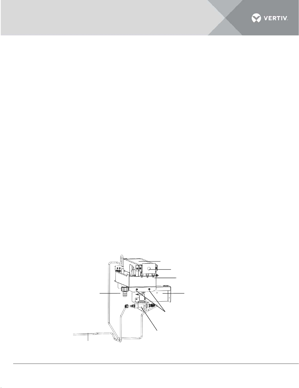
processing controller will send a humidification command and provide 24V power to it. Then the
顶部过温保护开关
加湿器上盖(内含加湿灯管)
注水电磁阀
加湿器水盘与固定支架之间的固定螺丝
加湿器固定支架
加湿器排水管
加湿器进水管
加湿器水盘
Up cov er (lamp in side)
Top over- temperature p rotection switch
Water tray
Brack et
Fixi ng screws between bracket an d water tray
Water supp ly solenoid val ve
Water supp ly pipe o f humidifier
Drai nage p ipe of humidifier
water filling valve will start the humidification operation.
The top temp-switch will act to cut off the lamp power to stop humidifying when abnormal airflow
causes high temperature around humidifier. The temp-switch should be reset manually to light up
the lamp as depicted in figure 4-3.
When the water tray is dry burned, the dry burned protection switch will act to cut off the lamp power
to stop humidifying. The dry burned protection switch should be reset manually to light up the lamp
as depicted in figure 4-4.
As the sediment exists in the water drained from the humidifier, the humidifier water tray should be
cleaned periodically to assure humidifier running efficiently. The cleaning cycle varies with the local
water quality It is recommended to clean (when necessary) the humidifier tray once in a month. Farinfrared humidifier itself automatic flushing function can effectively extend the time interval between
cleanings; however, regular inspection and maintenance are still essential.
The Cleaning steps are mentioned as following:
Remove the water level standpipe to drain the water tray;
Disconnect the drainage pipe;
Disconnect the power of lamp and the signal line of water high-level switch, dry burned protect switch and water
supply solenoid valve;
Remove the front fixing screws and disassemble humidifier kits;
Remove fixing screws between bracket and water tray, remove the Up cover kits. Pay attention to protecting the
lamp;
Remove the fixing screws at the two ends of the water tray, and pull out the water tray. Cleanse the water tray
with water and hard brush;
Restore the humidifier by reversing the preceding procedures.
Vertiv | Liebert DM Series Precision Air Conditioner | User Manual 73
Figure 4-3
Page 85
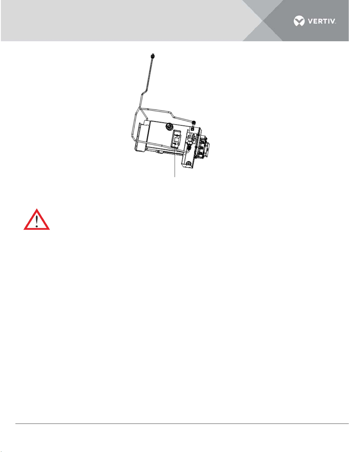
Figure 4-4
加湿水盘底部防干烧保护开关
Dry burned protection s witch
( at the bottom of water tray)
Before exercising the humidifier water tray cleaning operation, make sure that the power has been
turned off; and also ensure that the water in the water tray is not hot before draining the water from the
infrared humidifier water tray so as to avoid personal injury.
4.2.6 Power SPD
The position of the power SPD is depicted in Figure 4-5.
Vertiv | Liebert DM Series Precision Air Conditioner | User Manual 74
Page 86
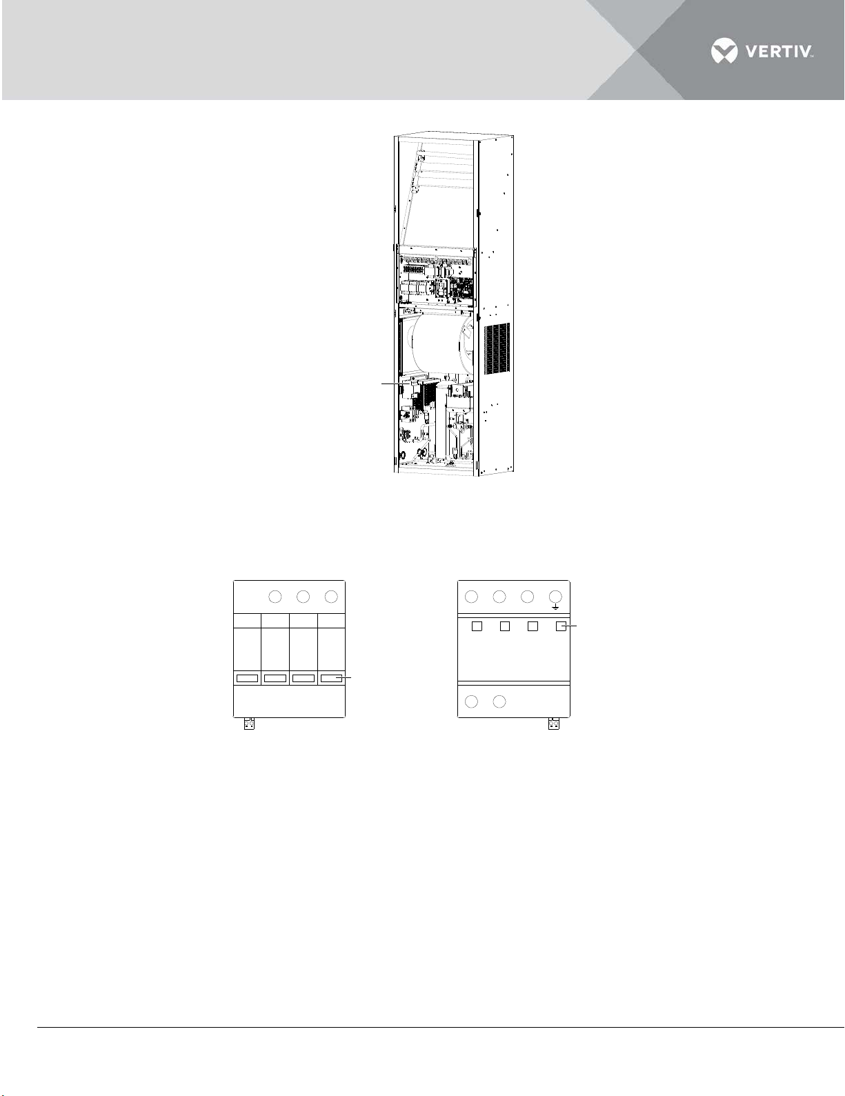
Figure 4-5
1-ph power SPD
ALARM
L/N
3-ph power SPD
Status indicator
(4 pcs)
ALARM
N N
L1
Status indicator
(4 pcs)
L/N
L2 L3
The power SPD has four status indicators, as depicted in Figure 4-6. The status indicators are green
during normal operation; they turn to red upon failure.
Figure 4-6
Vertiv | Liebert DM Series Precision Air Conditioner | User Manual 75
Page 87
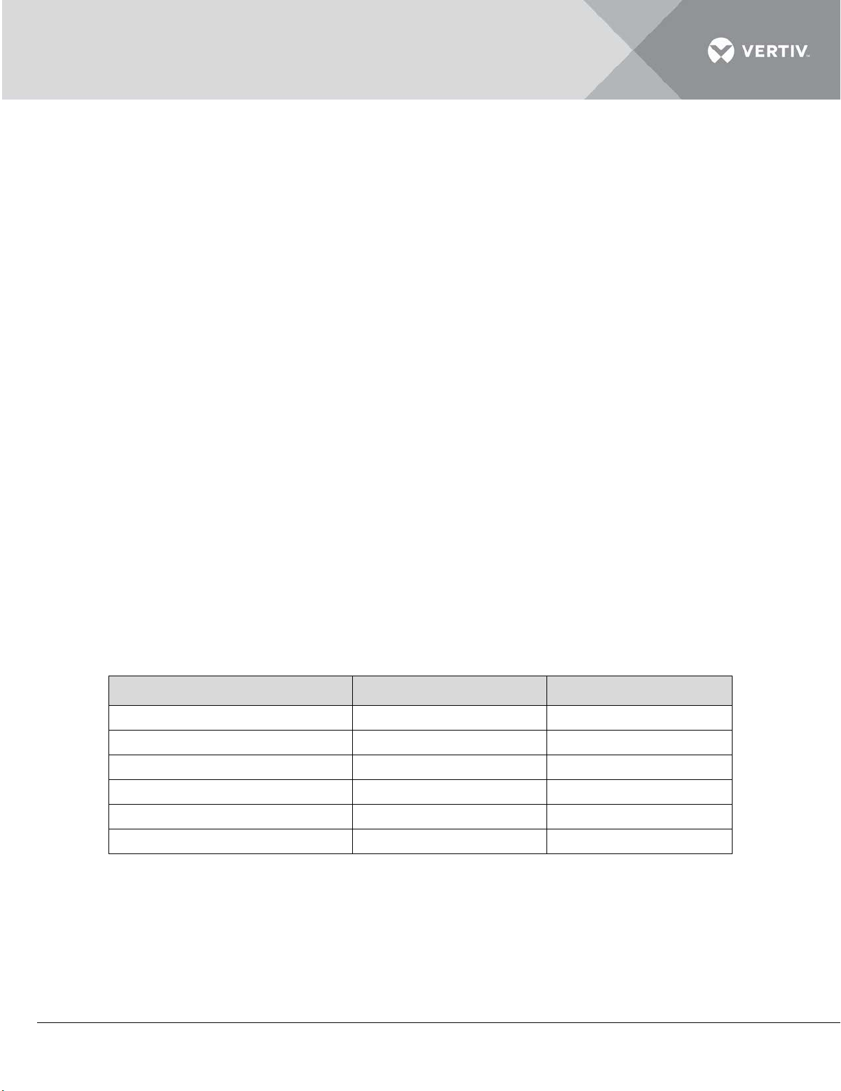
The power SPD does not need special maintenance. It needs a regular check for non-loosening and
Item
psig
MPa
Low pressure
57.5 ~ 99.8
0.397 ~ 0.67
Low-pressure setpoint
20
0.138
Low-pressure recovery point
36.3
0.25
High pressure
180 ~ 275
1.242 ~ 1.895
High-pressure setpoint
400
2.76
High-pressure recovery point
307
2.1
normal status indicating.
If any one of the following phenomena occurs, the power SPD has failed and it needs to be replaced
immediately.
1. Any indicator of the power SPD turns red.
2. The customer alarm 1 is generated (see SPD (Customer 1 terminal) in 6.5.1 Connecting Control
Terminals).
4.2.7 Thermal Expansion Valve
The thermal expansion valve keeps the evaporator supplied with sufficient refrigerant to satisfy load
conditions. Its proper operation can be determined by measuring the superheat level. The correct
superheat setting is 5.6°C to 8.3°C (10°F to 15°F).
4.2.8 High-Pressure Switch And Low-Pressure Switch
The discharge pressure and suction pressure will vary significantly with the AC unit load and ambient
conditions (Refer the table in Listing 4.1) during normal operation. When the discharge pressure rises
to the high-pressure setpoint, the high-pressure switch will activate and the control system will shut
down the compressor after ensuring an abnormal input signal of the high-pressure switch.
When the suction pressure is lower than the low-pressure set point, the low-pressure switch will
activate and the control system will shut down the cooling system after confirming.
Listing 4.1
Vertiv | Liebert DM Series Precision Air Conditioner | User Manual 76
Page 88
4.2.9 Compressor
The compressor fault is mainly classified into two types:
1. Motor faults (such as winding burnout, insulation failure, short-circuit between coils etc.).
2. Mechanical faults (such as compressing failure, relief valve fault, therm-o-disc fault and so on).
If the operation pressure is not built up, it signifies that the compressor has failed. It can be verified if
the suction pressure and discharge pressure are balanced and the motor does not rotate in reverse
direction.
The controller has powerful alarm and protection functions to ensure safe operation of the
compressor. The maintenance personnel should record the high pressure and low pressure and find
out the cause of an alarm protection during periodical maintenance and inspection.
Avoid touching or contacting the residual gas and oils in compressor with exposed skin. Wear long
rubber gloves to handle contaminated parts.
Check the following items before replacing the compressor:
Check that all fuses and circuit breakers are normal.
Check the working status of the high and low-pressure switches.
Check the relevant historical alarm information.
Check the historical operation records of the compressor.
Check the motor electric characteristic.
The system contains refrigerant. Reclaim the refrigerant using standard reclaiming equipment before
maintenance
To remove and replace the failed compressor adhere to the following procedure:
Cut off the power.
Attach suction and discharge gauges to compressor access fittings.
Reclaim the residual refrigerant by using standard reclaiming procedures.
Releasing of refrigerant to the atmosphere is harmful to the environment. Refrigerant must be recycled in
accordance with state and local regulations.
Vertiv | Liebert DM Series Precision Air Conditioner | User Manual 77
Page 89

Remove the failed compressor.
Install replacement compressor and assemble all the connections. Carry out the pressurization and leakage tests
to the system at approximately 150psig (1034kPa).
Evacuate the system twice to 1500 microns and the third time to 500 microns. Break the vacuum each time with
clean and dry refrigerant to 2psig (13.8kPa).
Charge the system with refrigerant based on the requirements of the evaporator, condenser and refrigeration
lines.
Apply power to and operate the AC unit. Check for proper operation. Refer to the circulation suction pressure
and discharge pressure ranges in normal operation, and supplement some refrigerant if necessary.
4.3 Outdoor Unit Maintenance
4.3.1 Refrigeration System
The components of the refrigerant system should be inspected monthly to find out if any abnormal
operations are occurring. Refrigerant pipes must be properly fixed and not allowed to vibrate against
the wall, floor or the unit frame. All the refrigerant pipes should be inspected biannually for any signs
of wear and tear.
4.3.2 Air-Cooled Condenser
When the airflow through the outdoor unit is restricted, use the compressed air or fin cleaner to clean
the condenser off the dust and debris that inhibit airflow. The compressed air should be blown at the
reversed airflow direction. In winter, do not let snow to accumulate on the side or underneath the
condenser. Check for bent or damaged fins and simply repair them if necessary. Check all refrigerant
pipes and capillaries for vibration and support them if necessary. Carefully inspect all refrigerant
pipes for signs of oil leakage, determining the leakage position.
4.3.3 Low-Temperature Unit Of Low-Temp Outdoor Unit
The liquid level of the refrigerant should be checked periodically in the fluid reservoir to ensure that
no refrigerant leakages occur. For detailed operation, refer to section 3.3.5 Checking Refrigerant
Charge Capacity of Low-Temp Outdoor Unit.
Periodically check whether the heating belt of the fluid reservoir works normally. See following for
details:
When the system is powered on and is in the standby mode, the fluid reservoir pressure is lower than
0.85Mpa, the heating belt preheats the fluid reservoir. If there is no heating, check whether the fuse
of the heating belt is blown or if the pressure switch is working normally. After confirming the fault
part(s), replace them.
Vertiv | Liebert DM Series Precision Air Conditioner | User Manual 78
Page 90
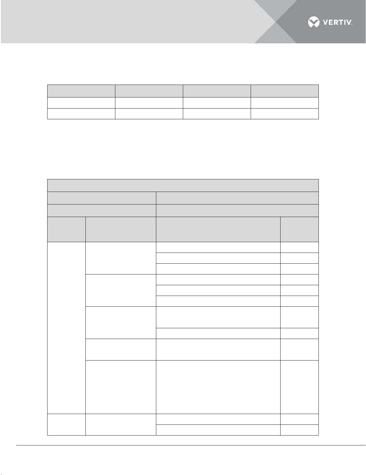
The heating belt fuse specifications in Table within listing 4.2.
Manufacturer
Model
Voltage
Rated current
Bussmann
S500-1A
250V
1A
Littelfuse
0217001
250V
1A
Liebert DM AC
Date:
Prepared by:
Model:
Serial Number:
Type
Maintenance
components
Item
Result
Check for restricted airflow
Check the filter
Clean the filter
Check if the water tray is clogged.
Check the humidifier lamp
Check the sediment of water tray
Impellers free of debris and move
Bearings in good condition
Power SPD
SemiSigns of oil leaks
Vibration isolation
Listing 4.2
4.4 Maintenance Inspection Checklist
Regular inspections are necessary to ensure proper operation of the AC unit.
Listing 4.3
Monthly
annually
Filter
Humidifier
(if applicable)
Indoor unit fan
(if applicable)
Drain system
(including
condensate pump)
Compressor
freely
Check for indicator color
Check and clean out unit drain pipes,
humidifier and tray, condensate
pump and building drain pipes
Vertiv | Liebert DM Series Precision Air Conditioner | User Manual 79
Page 91
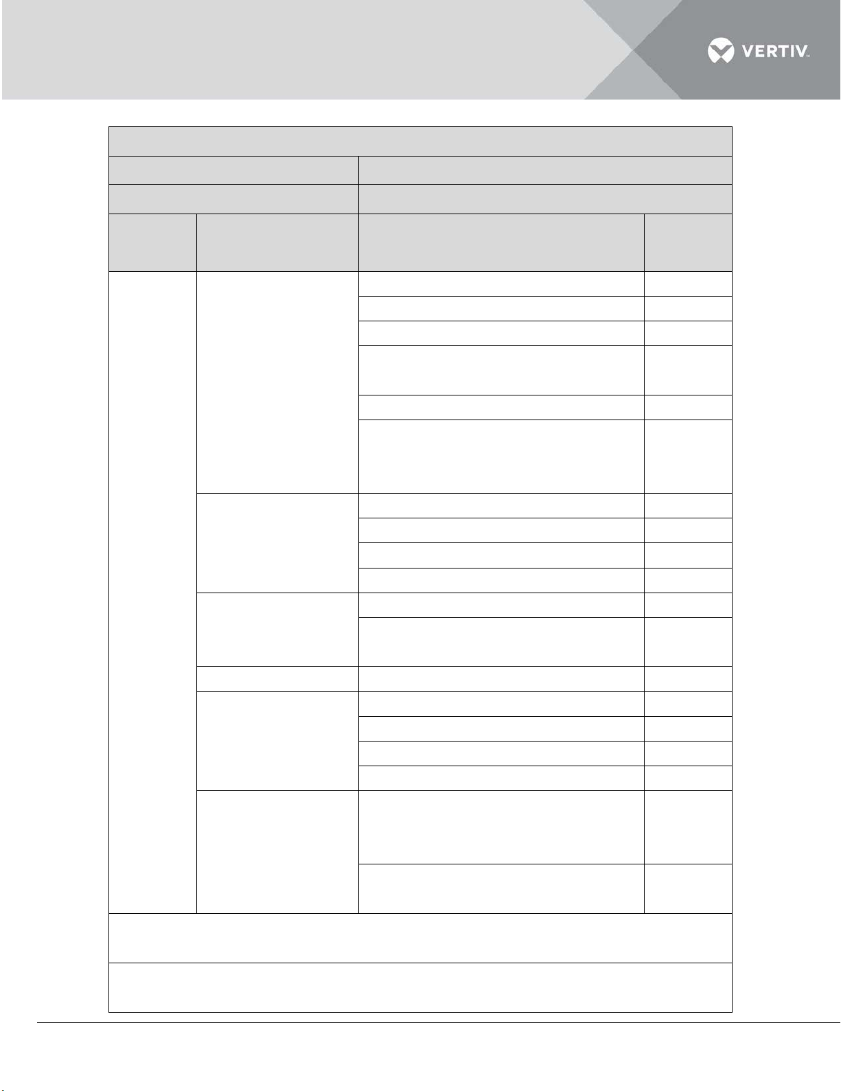
Liebert DM AC
Date:
Prepared by:
Model:
Serial Number:
Type
Maintenance
components
Item
Result
Refrigerant system
Suction pressure
Discharge pressure
Superheat
Evaporator in tight and clean
Charging capacity of refrigerant
Evident temperature difference
Condenser coil is clean
Motor mounted tightly
Bearing in good condition
Refrigerant pipes properly supported
Check electrical connections
Check the surface for signs of
Electric heater
Check for signs of corrosion
Check if the water tray is clogged
Check the humidifier lamp
Check the sediment of water tray
Check and fix connectors
Check for the liquid level of the
Check whether the heating belt of
Notes:
Signature:
Air-cooled
condenser
Electric board
Humidifier
condition
between before and after the filter
drier
corrosion
Low-Temp low-
refrigerant in fluid reservoir and leak
of the fluid reservoir fittings
temperature unit
the fluid reservoir works normally
Vertiv | Liebert DM Series Precision Air Conditioner | User Manual 80
Page 92
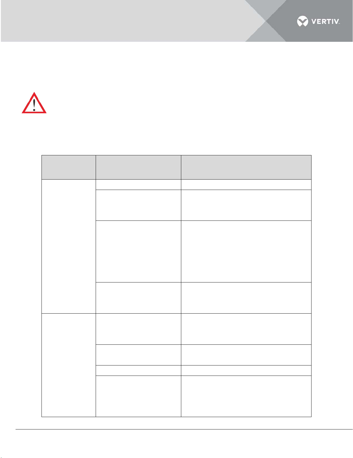
4.5 Troubleshooting
Fault
phenomenon
Possible cause
Check or remedy
No power to unit
Check unit input voltage
Circuit breaker that
Check jumping cables on the control
Check for 24Vac ± 2Vac at the winding.
High compressor
See ‘High-pressure alarm’ for checking
Plugged strainer
Clean or replace the strainer
Use suction and discharge pressure
Troubleshooting is to be performed by the trained and qualified service personnel. However, the
checklists have been provided just for reference purpose.
Certain circuits carry lethal voltages. Only professional technicians are allowed to maintain the
machine. Extreme care and caution is required while troubleshooting online.
If jumpers are used for troubleshooting, remember to remove the jumpers after the troubleshooting,
failing which the connected jumpers may bypass certain control functions and increase the risk to the
equipment.
Listing 4.4
Unit does not
start
No cooling
controls voltage (at the
transformer) is open
Float switch relay has
closed due to high water
level in the condensate
pump sump
Jumping cables not in
place
Compressor contactor
not pulling in
discharge pressure
Locate short circuit and reset circuit
breaker
Check that drain pipes and pipelines are
clogged or that the condensate pump is
damaged
board
If the voltage is right, check the
contactor
and maintenance descriptions
Low refrigerant charge
gauge to check the pressure. View
whether evident bubbles exits through
the sight glass
Vertiv | Liebert DM Series Precision Air Conditioner | User Manual 81
Page 93
Fault
phenomenon
Possible cause
Check or remedy
Insufficient airflow across
Remove debris from coil surface and air
Check that the cable connection from
Set Heat to ‘ON’, refer to Select Options
No heat demand output
Adjust temperature setpoint and
Turn off the power. Check the element
Disconnect the system power, and then
Loose connection
No display,
Disconnection between
No display,
Low power voltage
Check for power voltage
Low-pressure
Refrigerant leakage
Check for leaking place and re-charge
condenser
inlet; check the control board for the fan
speed regulation performance
High-pressure
alarm
Heater does
not operate
Display
abnormal
Condenser fan not
operating
Heat function disabled in
Select Options menu
from the control system
Elements burned out
Static discharge
between display board
and control board
the control board to the terminal block
of outdoor unit is tight; check that the
outdoor unit connections are tight;
check that the condensate pressure
sensor works normally
in
3.4.5 System Menu
sensitivity within the required range
resistance with a multimeter
restart
Tighten the connection after powering
off, and then restart
control buttons
display board and control
board and control board
Check the connection between display
do not respond
board
and equipment
operates
Display board fault Replace the display board
normally
control buttons
Communication between
do not respond
Check the connection between control
control board and display
and equipment
has no output
board interrupted
board and display board
Vertiv | Liebert DM Series Precision Air Conditioner | User Manual 82
Page 94
Fault
phenomenon
Possible cause
Check or remedy
alarm
Outdoor ambient
temperature too low
Low-temperature
Heater operation current
Setpoint unreasonable
Reset the setpoint
Vapor barrier not done in
Low humidity
Check that the water supply is normal
Check that the water supply solenoid
Check the state of the high water-level
Check that the water supply pipe is not
The humidification
Check if the contactor voltage is normal
Contact local maintenance engineer
Hightemperature
alarm
Low
temperature
alarm
Outdoor unit fan running
at full speed upon low
outdoor ambient
temperature
High-temperature
setpoint unreasonable
Room load exceeding
unit design ability
setpoint unreasonable
improper
Check that the cable connections of
outdoor unit are normal; check that the
condensate pressure sensor is normal
Reset the setpoint
Check for room seal or make capacity
expansion
Reset the setpoint
Check for heater working operation
High humidity
alarm
Check for the vapor barrier
the room
Setpoint unreasonable Reset the setpoint
alarm
valve is working
Humidification
ineffective
No water in the water tray
switch and water level regulator
clogged
Vertiv | Liebert DM Series Precision Air Conditioner | User Manual 83
Page 95
Fault
phenomenon
Possible cause
Check or remedy
contactor does not close
Check if the safety devices of the
infrared humidifier are opened such as
Check L1, L2 and L3 voltages are normal
Check if the manual reset switch of
Infrared humidifier lamp
the over-temperature protection switch
and dry burned switch.
Humidifier main power
failure
burned
when the contactor is energized.
humidifier is disconnected.
Replace the lamp
Vertiv | Liebert DM Series Precision Air Conditioner | User Manual 84
Page 96
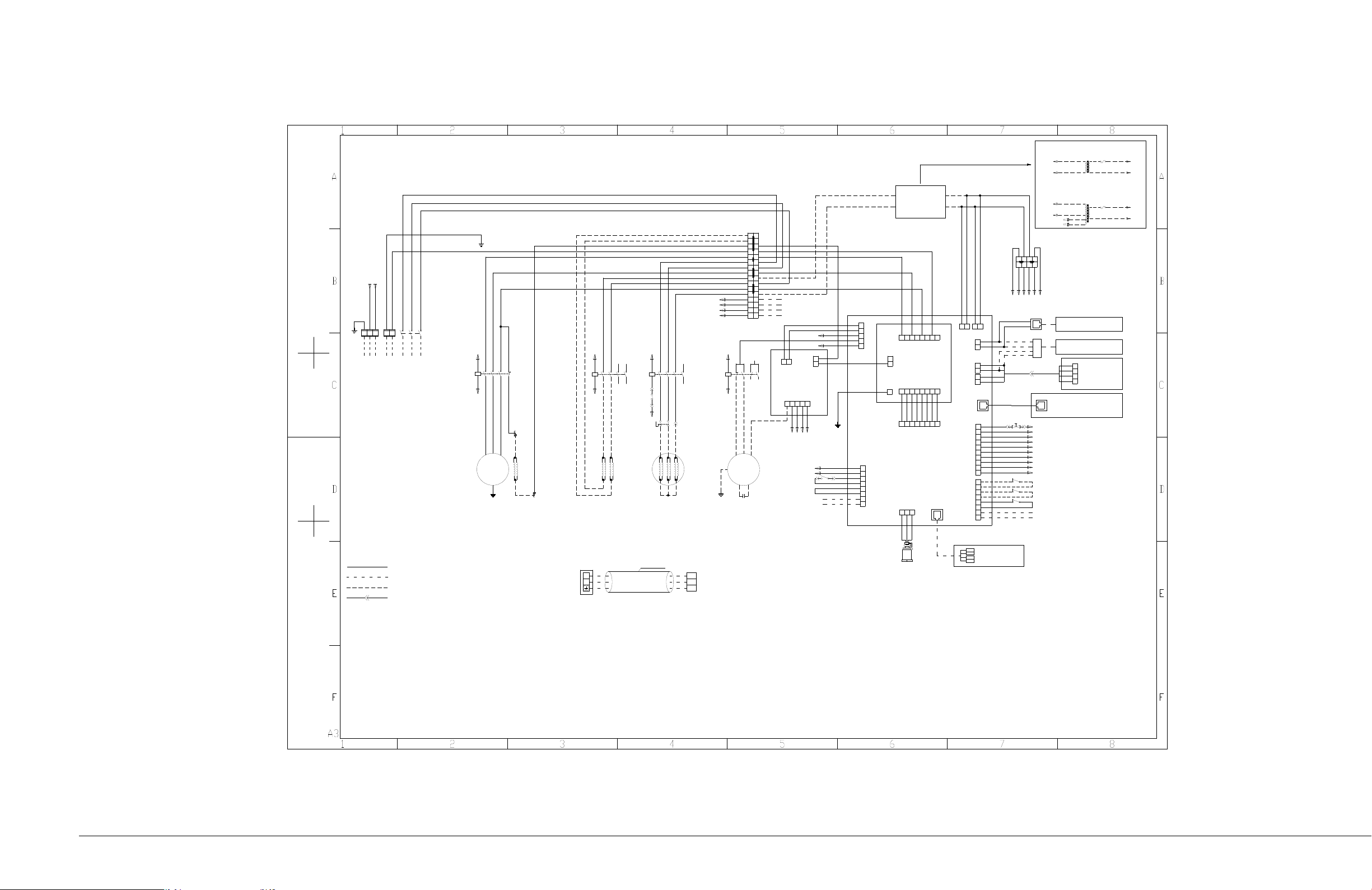
APPENDIX 1 - Crcuit Diagrams
4
黑
2
黑
6
黑
3
4
1
2
A1
A2
5
6
21
22
31 5
Main switch
PE N
压缩机
控制板
J28
J21
3
4
5
6
7
8
1
2
高压开关/High Pressure Switch
低压开关/Low Pressure Switch
21
21
PTC电加热
PTC Heater
风机
启动电容
Capacitor
压缩机电加热带
Comp.Heater
电源板
滤波板
3
4
1
2
KM1
3
4
5
6
7
821
3
4
5
6
7
821
1
2
1
2
1
3
4
5
2
J13 J31
J1
J3
J02
J01
J03
J29
J30
J18
1
3
4
5
2
6
8
9
10
7
1
3
4
5
2
6
8
7
1
3
4
5
2
6
8
7
J19
J12
J39
2
1
2
1
4
2
1
3
J4
显示板
1
电控盒接地点
GND
排气开关/Exhaust Switch
地板溢水/Water Under FLoor Switch
3 2 1
J23
J34
J14
2
1
备机请求/Lead/standbyrequirement
J36
GND
+12V
CANH
CANL
温湿度检测板
节能卡
压力传感器
Pressure Sensor
23
J2
12
蓝
棕黑 灰
黑黑 黑
线电压线路/Line voltage wiring
现场安装线/Locale wiring
器件自带线/Device own wiring
线体说明/Wire Description:
室外接 线端子
Outdoor Terminal block
N
L
L1
N1
室内端子 排
Indoor Terminal block
电控盒接地点
GND
电控盒接地点
GND
室内外连接电缆
Connection cable
12V
GND
A
B
GND
12V
A
B
端子对插线/Quick disconnect wiring
黄/绿
5
6
A1
A2
室内接线端子TB2
Terminal Block 2
黑
QF-1
QF-3
QF-5
KM1-1
KM1-3
KM1-5
KM1-21
KM1-2
KM1-4
KM1-6
T1T2T3
KM2-1
KM2-3
TB1-1
TB1-3
TB1-7
TB1-9
TB1-13
TB1-15
TB1-N
TB1-2
TB1-8
TB1-14
TB1-N
TB1-N
J1-L
J02-1
J1-N
J01-1
J01-3
J01-5
J01-7
J18-1
J18-2
J18-3
J2-2
J2-1
TB2-25
WV-2
J28-3
J28-4
J28-1
J28-2
TB2-27
KM2-A2
TB2-29
J03
N
PE
J19-7
J19-8
J19-4
J19-3
J19-2
J19-1
J28-4
+5V
VIN
GND
远程开关机/Remote ON/OFF
J28-7
J28-8
J19-5
J19-6
13
14
黑 黑
5
3
1
8
7
KA1-5
45
1
J18-4
蓝黑 白
黄/绿
J28-5
J28-6
KA1-7
TB2-32
KM2-A1
J28-6
KA1-8
BK BK BK BK
灰
灰
黑
黑
蓝
蓝
黑
棕
黑 绿 红
黑
黑
黄/绿
黑
黑
黑
黑
J3-4
J28-9
J28-10
KM1-22
TB1-17
TB1-19
TB1-21
TB1-23
室内接线端子TB1
Terminal Block 1
N
N
N
N
N
N
N N
TB1-17
TB1-19
TB1-21
TB1-23
黑
黑
黑
黑
黑
黑
黑
黑
棕
黑
PE1
J3-2
J3-1
RDU-SIC
DB9
电控盒接地点/GND
L1 N1
PE1
380V/50Hz 3N~
KM2 KA1
J28-3
TB2-25
L1N1
KM1-A1
J3-4
J18-3
KM1-A2
J28-5
TB2-26
棕 棕蓝 蓝
J28-7
J28-8
J28-9
J28-10
黑黑
SPD-NC
SPD-COM
25 2729 31
26 2830 32
TB2-27
TB2-26
TB2-29
TB2-31
TB2-32
J3-1
J3-2
RDU-A
A
B
BKBK BK
BL
Y/G
BKBK
BKBK BK BK BK BK
Compressor
Fan
Display
Y/G
BRBK GR
BLBK WH
BR BRBL BL
BK
BK
BK
BK
BK
BK
Y/G
黑 黑 黑 黑
Power board
Control board
Filter
Temp.and Hum.
detection board
BK
BK
BL
BL
BK
BR
BK
BK
BK
BK
BK
BK
BK
BK
BR
BK
GR
GR
BK G R
接线说明/Wiring Diagram Description:
1、此接线图用于7.5KW和12.5KW机型。/This wir ing diagram for 7.5KW and 12.5KW models.
2、单冷机型无"电加热接触器KM2"、"电加热"、"加湿接触器K M3"、"内风机继电器KA1"、"红外加湿器"及相关电缆。
/Cooling only models without Hea ter contactor KM2,Heater,Humidif ier contactor KM3,Fan relay KA1,
Infrared
Humidifier and relate cables.
3、加热机型无"加湿接触器KM3"、"内风机继电器KA1"、"红 外加湿器"及相关电缆。
/Heating models without Humidifi er contactor KM3,Fan relay KA1,
Infrared
Humidifier and relate cables.
4、单冷机型和加热机型无"内风机继电器KA1",内风机黑色抽头直 接接到J18-4端子上,蓝色抽头用闭端端子压接后扎于电控盒外。
/Cooling only models and Heating models without Fan relay KA1,Bl ack wire connect to terminal J18 -4,Blue wire tied with a closed- end terminal.
5、变压器T2、接线端子TB2为加热和加湿选配时增加,单冷机型无 变压器T2和接线端子TB2。
/Cooling only models without T2 and TB2.
6、单冷机型变压器T1型号为DME07MCT1T1,加热和加湿选 配时变压器T1型号为KL-LSF24A-T1。
/Transformer T1's type of coolin g only models is DME07MCT1T1,of other models is KL-LSF24A-T1
7、节能卡、监控卡、RDU-A为选配件,如有需求客户现场接线。/ Energy-saving card,SIC and RDU-A are optional.
8、版本代码为T的机组标配电源防雷器;版本代码为P的机组无电源防 雷器及相关电缆,控制板J19-1和J19-2用电缆短接。
/Version code T models with Powe r SPD, Version code P models wit hout Power SPD and relate cables ,connect J19-1 and J19-2 with a short
connection cable.
电源空开
Energy-saving card
到室外机
TO Outdoor
Unit
备机有效Lead/standby
switch over
公共告警
General alarm
配线色 标/Wire color code:
BK-Black/黑色 GR-GRAY/灰 色
R-Red/红色
WH-White/白色
BL-Blue/蓝色
BR-Brown/棕色
Y/G-Yellow green/黄绿 色
YE-Yellow/黄色
G-Green/绿色
黑BK
棕BR
黑BK
BR 棕
黑BK
黑BK
3
4
1
2
5
6
A1
A2
KM3-1
KM3-3
13
14
黑 黑
KM3
白 白
BK BK
WH WH
白
WH
KM3-5
黑
BK
J18-5
黑
KM3-A2
BK
J18-5
J3-3
KM3-A1
TB1-N
高水位告警/High Water Alarm
底盘防干烧开关
TS2
顶部过温开关
TS1
J3-3
红外加湿器
Humidifier
棕BR棕
BR
J28-2
TB2-31
WV-2WV-1
12
J21-5
J21-6
KM3-2
KM3-4
KM3-6
TS2-1TS2-2
TB1-5
TB1-11
HWAHWA
N2 L2 HL3
N1 L1 HL3
11
109
8
7
65
43
21
1413
1615
1817
2019
2221
2423
TB1-4
TB1-6
TB1-12
42
6
变压器T1
Transformer1
变压器T1接线方式详见框内标识
加热加湿机型变压器T1接线方式
黄
BK
黄
R
保险丝/Fuse
YE
G
YE
YE
黑
红
黄
绿
保险丝/Fuse
黄
BK
黄
BK
YE
YE
黑
黑
TB1-14
TB1-16
TB1-14
TB1-16
单冷机型变压器T1接线方式
Vertiv | Liebert DM series Air Conditioner | User Manual 86
Page 97
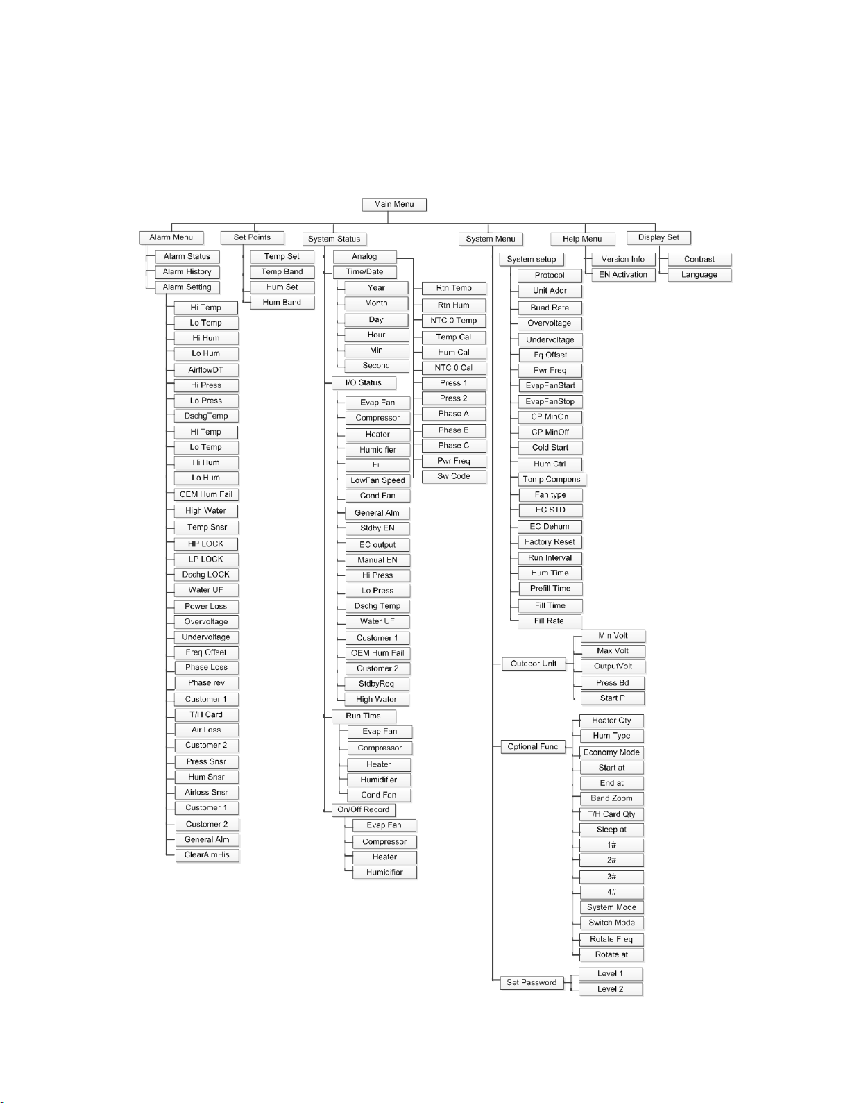
APPENDIX 2 Menu Structure
Vertiv | Liebert DM series Air Conditioner | User Manual 87
Page 98
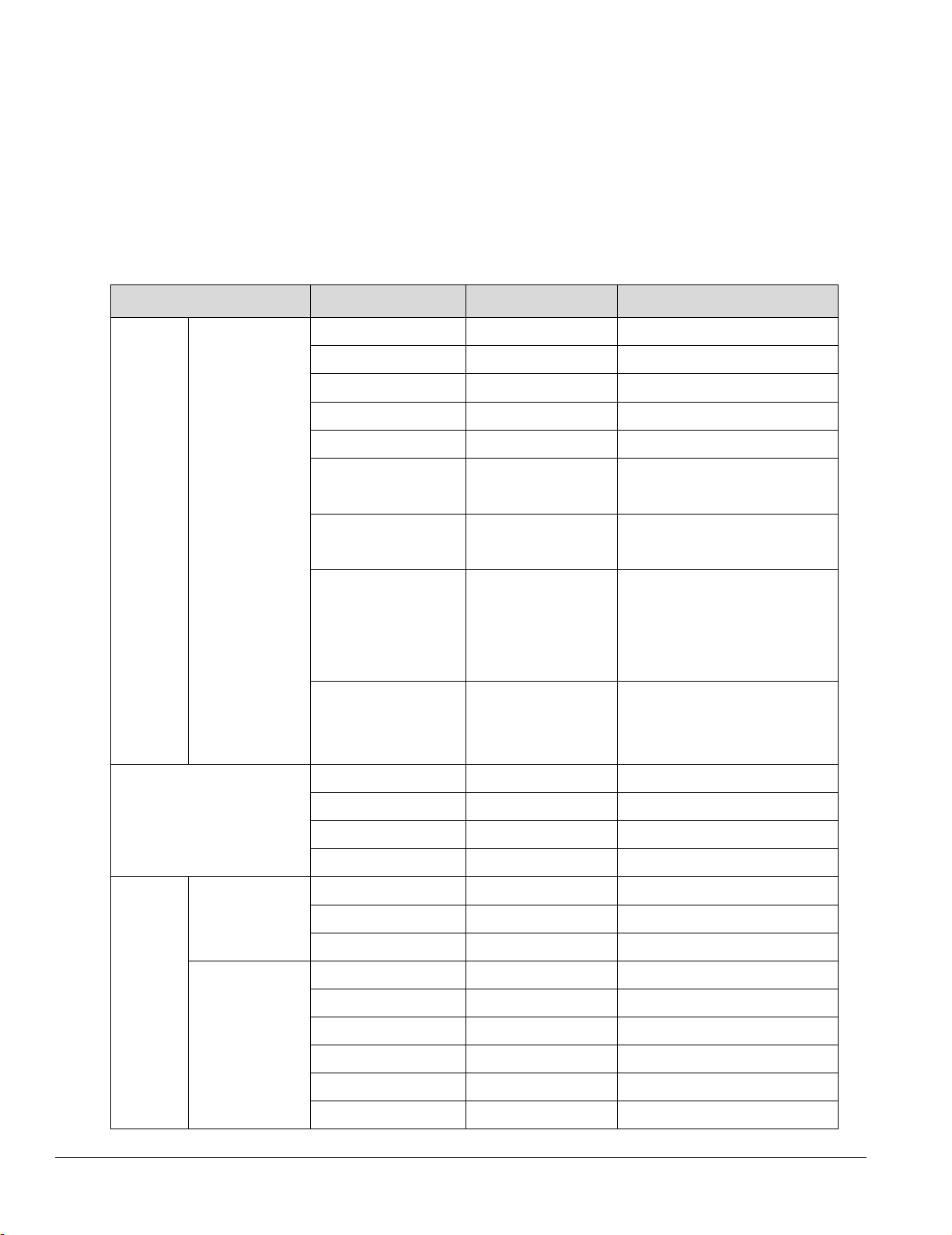
APPENDIX 3 Parameter Setting
Menu
Parameter
Default
Setting range
Hi Temp
35°C
25°C ~ 50°C
Lo Temp
15°C
5°C ~ 20°C
Hi Hum
65%RH
65%RH ~ 90%RH
Lo Hum
35%RH
10%RH ~ 35%RH
AirflowDT
25°C
30°C
Alarm Setting
Alarm Setting
NC (the unit
Customer 2
Temp Set
24°C
15°C ~ 35°C
Temp Band
3°C
1°C ~ 5°C
Hum Set
50%RH
20%RH ~ 80%RH
Hum Band
5%RH
1%RH ~ 10%RH
Temp Cal
0.0°C
-10°C ~ +10°C
Hum Cal
0.0%
-10% ~ +10%
NTC0 Cal
0.0°C
-10°C ~ +10°C
Manual En
N
Y, N
Evap Fan
OFF
ON, OFF
Compressor
OFF
ON, OFF
Heater
OFF
ON, OFF
Humidifier
OFF
ON, OFF
LowFanSpeed
OFF
ON, OFF
Table
Alarm
Menu
Set Points
Alarm
Setpoint
Analog
(general alarm)
(serious alarm)
Customer 1
(remote
shutdown)
EN MSG, EN, DIS
EN DIS, EN
equipped with
NO, NC
SPD is NC by
default)
NC NO, NC
System
Status
Vertiv | Liebert DM series Air Conditioner | User Manual
I/O Status
88
Page 99
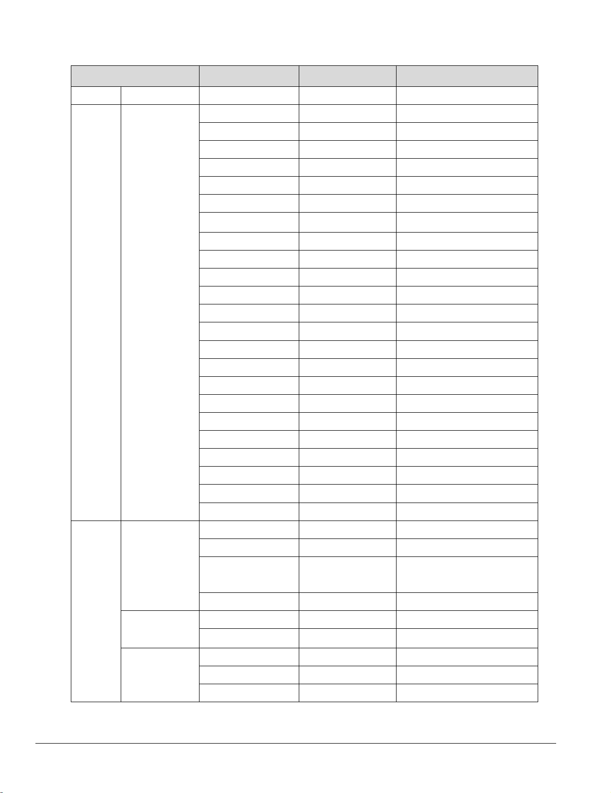
Menu
Parameter
Default
Setting range
Cond Fan
OFF
ON, OFF
Protocol
1
1 ~ 254
Unit Addr
YDN23
YDN23, MODBUS
Baut Rate
19200
1200 ~ 19200
Overvoltage
15%
10% ~ 30%
Undervoltage
15%
10% ~ 30%
Fq Offset
3Hz
2Hz ~ 5Hz
Pwr Freq
50HZ
50Hz,60Hz
EvapFanStart
10s
10s ~ 600s
EvapFanStop
30s
10s ~ 300s
CP MinOn
180s
60s ~ 300s
CP MinOff
180s
60s ~ 300s
Cold Start
180s
30s ~ 240s
Hum Ctrl
RH
RH, AH
Temp Compens
OFF
ON, OFF
Factory Reset
NO
YES, NO
Fan type
AC
AC, EC
EC STD
75%
50% ~ 100%
EC Dehum
65%
40% ~ 90%
Run Interval
10h
5h~25h
Hum Time
8min
1min~30min
Prefill Time
30s
10s~300s
Fill Time
7s
1s~900s
Fill Rate
150%
100%~500%
Min. Volt
30%
30% ~ 50%
Max. Volt
100%
60% ~ 100%
OutputVolt
Start P
13Bar
11Bar ~ 15Bar
Optional
Heater Qty
0
0, 1
Hum Qty
0
Optional
Economy Mode
OFF
OFF, ON
Start at
22:00
18:00 ~ 3:00
End at
7:00
5:00 ~ 10:00
System
Menu
System
Setup
Outdoor
Unit
Press Bd
5Bar 4Bar ~ 6Bar
System
Menu
Vertiv | Liebert DM series Air Conditioner | User Manual
Func
Func_CostS
ave
0、IF
89
Page 100
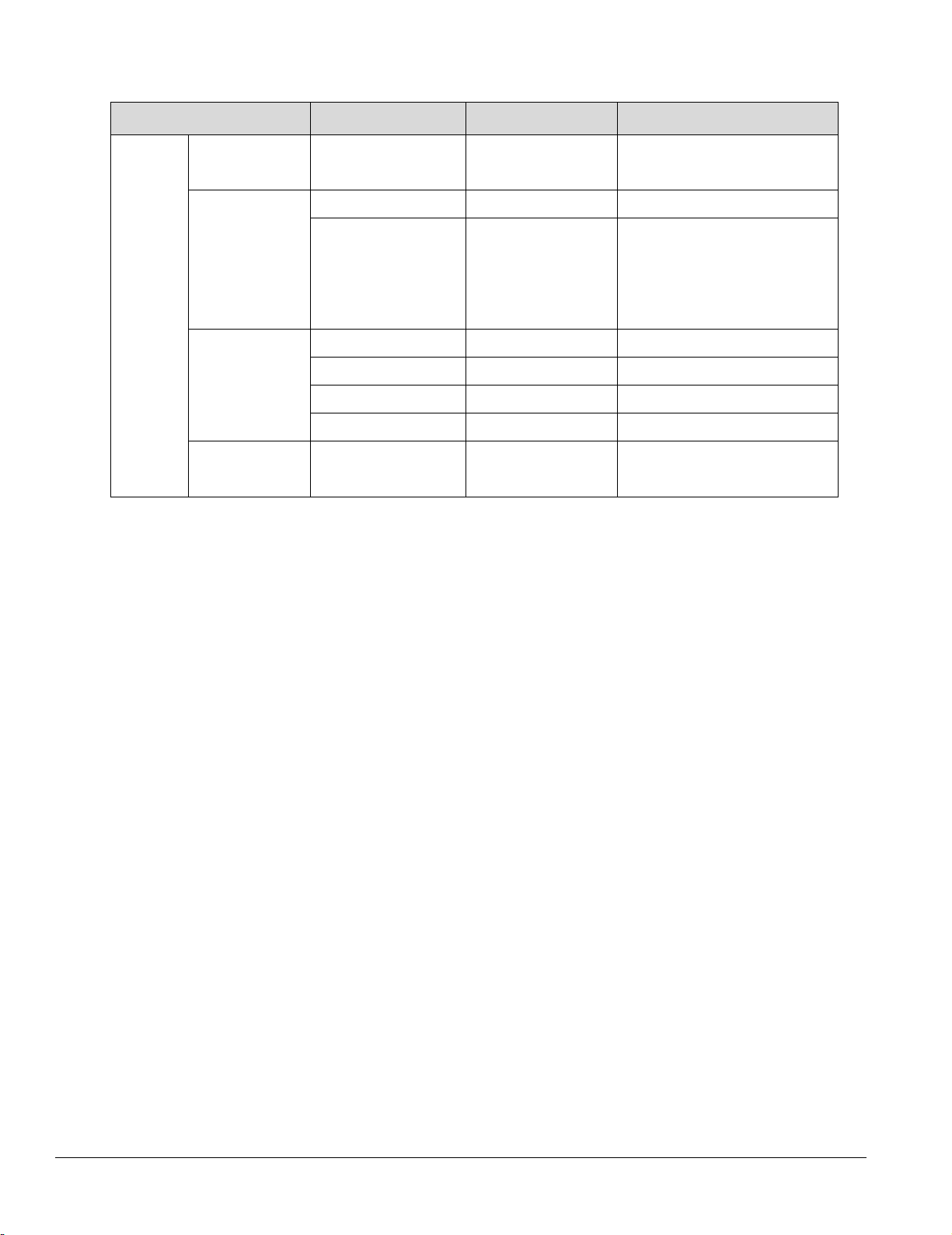
Menu
Parameter
Default
Setting range
Mod_Econo
my Mod
Optional
T/H Card Qty
0
0 ~ 4
System Mode
SIGL
SIGL, HOST, SPAR
Switch Mode
STDB
STDB, ROTA
Rotate Freq
Day
1DAY ~ 7Day
Rotate at
12:00
0:00 ~ 23:00
Set
Func_CostS
Band Zoom 2°C 2°C ~ 10°C
ave
Mod_Sleep
Mod
Optional
Func_Stand
by
Password
Sleep at 27°C 15°C ~ 40°C
Level 1 0001 ~ 9999
Vertiv | Liebert DM series Air Conditioner | User Manual
90
 Loading...