

Page 1

Liebert®
CW™ ThermalManagementSystem
Installer/User Guide
340kW to 440 kW Capacity, 60Hz
Page 2

The information contained in this document is subject to change
without notice and may not be suitable for all applications. While
every precaution has been taken to ensure the accuracy and
completeness of this document, Vertiv assumes no responsibility
and disclaims all liability for damages resulting from use of this
information or for any errors or omissions. Refer to other local
practices or building codes as applicable for the correct methods,
tools, and materials to be used in performing procedures not
specifically described in this document.
The products covered by this instruction manual are manufactured
and/or sold by Vertiv This document is the property of Vertiv and
contains confidential and proprietary information owned by Vertiv.
Any copying, use or disclosure of it without the written permission
of Vertiv is strictly prohibited.
Names of companies and products are trademarks or registered
trademarks of the respective companies. Any questions regarding
usage of trademark names should be directed to the original
manufacturer.
Technical Support Site
If you encounter any installation or operational issues with your product, check the pertinent
section of this manual to see if the issue can be resolved by following outlined procedures.
Visit https://www.VertivCo.com/en-us/support/ for additional assistance.
Vertiv |Liebert® CW™ Installer/User Guide
Page 3

TABLE OF CONTENTS
1 Important Safety Instructions 5
2 Nomenclature and Components 9
2.1 Liebert CW Model-number Nomenclature 9
2.2 Component Location 10
3 Planning Guidelines 11
3.1 Capacity and Physical Data 11
3.2 Shipping Dimensions and Unit Weights 12
3.3 Planning Dimensions 13
4 Pre-installation PreparationandGuidelines 15
4.1 Site Preparation 15
4.1.1 Preparing a Concrete Slab 15
5 Equipment Inspection and Handling 17
5.1 Hardware Kit 17
5.2 Rigging 18
6 Installing the Unit 21
6.1 Connecting Unit Sections (Recommended) 23
6.2 Routing the Filter-clog Pick-up Tube in the Plenum 24
7 Electrical Connections in the Unit 25
7.1 Fan High-voltage connections 25
7.2 Fan-control Low-voltage connections 25
7.3 Condensate-pump High- and Low-voltage Connections 27
8 Piping Requirements 29
8.1 Installing Water Supply and Return Piping 29
8.2 Installing Drain Traps on a Unit without a Condensate Pump 29
8.3 Installing Condensate-discharge Tubing on Units with a Condensate Pump 31
8.4 Flushing the Entire Water System before Start-up 32
Appendices 33
Appendix A: Technical Support and Contacts 33
Appendix B: Optional Configuration forLiebert®CW440Seismic Application 35
Appendix C: Submittal Drawings 37
Vertiv | Liebert® CW™ Installer/User Guide | 3
Page 4

Vertiv | Liebert® CW™ Installer/User Guide | 4
Page 5

1 IMPORTANT SAFETY INSTRUCTIONS
SAVE THESE INSTRUCTIONS
This manual contains important safety instructions that should be followed during the installation and
maintenance of the Liebert®CW. Read this manual thoroughly before attempting to install or operate this
unit.
Only qualified personnel should move, install or service this equipment.
Adhere to all warnings, cautions, notices and installation, operating and safety instructions on the unit
and in this manual. Follow all installation, operation and maintenance instructions and all applicable
national and local building, electrical and plumbing codes.
WARNING! Arc flash and electric shock hazard. Open all local and remote electric power-supply
disconnect switches, verify with a voltmeter that power is Off and wear appropriate,
OSHA-approved personal protective equipment (PPE) per NFPA 70E before working within the
electric control enclosure. Failure to comply can cause serious injury or death. Customer must
provide earth ground to unit, per NEC, CEC and local codes, as applicable. Before proceeding
with installation, read all instructions, verify that all the parts are included and check the
nameplate to be sure the voltage matches available utility power. The Liebert® controller does
not isolate power from the unit, even in the “Unit Off” mode. Some internal components require
and receive power even during the “Unit Off” mode of the controller. The only way to ensure
that there is NO voltage inside the unit is to install and open a remote disconnect switch. Refer
to unit electrical schematic. Follow all local codes.
WARNING! Risk of improper moving. Can cause equipment damage, injury or death. Use only
lifting equipment that is rated for the unit weight by an OSHA-certified rating organization. The
center of gravity varies depending on the unit size and selected options. The slings must be
equally spaced on either side of the center of gravity indicator.
Shipping weights and unit weights are listed in the tables in Shipping Dimensions and Unit
Weights on page12. Use the center of gravity indicators on the unit to determine the position of
the slings.
WARNING! Risk of improper lifting. Can cause equipment damage, injury, or death. A spreader
bar or equivalent must be used when rigging to ensure the lifting force is completely vertical at
these fasteners. Lift points are rated for lifting this section only. Do not lift assembled sections
from these lift points.
WARNING! Risk of contact with high-speed, rotating fan impeller blades. Can cause injury or
death. Open all local and remote electric power-supply disconnect switches, verify with a
voltmeter that power is off, and verify that all fan impellers have stopped rotating before
working in the unit cabinet.
WARNING! Risk of top-heavy unit falling over. Improper handling can cause equipment
damage, injury or death. Read all of the following instructions and verify that all lifting and
moving equipment is rated for the weight of the unit before attempting to move, lift, remove
packaging from or prepare the unit for installation.
1 ImportantSafety Instructions 5
Page 6

NOTICE
NOTICE
CAUTION: Risk of contact with sharp edges, splinters, and exposed fasteners. Can cause
injury. Only properly trained and qualified personnel wearing appropriate, OSHA-approved PPE
should attempt to move, lift, remove packaging from or prepare the unit for installation.
Risk of improper power-supply connection. Can cause equipment damage and loss of warranty
coverage.
Prior to connecting any equipment to a main or alternate power source (for example: back-up
generator systems) for start-up, commissioning, testing, or normal operation, ensure that these
sources are correctly adjusted to the nameplate voltage and frequency of all equipment to be
connected. In general, power-source voltages should be stabilized and regulated to within
±10% of the load nameplate nominal voltage. Also, ensure that no three-phase sources are
single-phased at any time.
Risk of piping-system corrosion and freezing fluids. Can cause leaks resulting in equipment
and very expensive building damage. Cooling coils and piping systems are at high risk of
freezing and premature corrosion. Fluids in these systems must contain the proper antifreeze
and inhibitors to prevent freezing and premature coil and piping corrosion. The water or
water/glycol solution must be analyzed by a competent local water treatment specialist before
start up to establish the inhibitor and antifreeze solution requirement and at regularly
scheduled intervals throughout the life of the system to determine the pattern of inhibitor
depletion.
The complexity of water/glycol solution condition problems and the variations of required
treatment programs make it extremely important to obtain the advice of a competent and
experienced water treatment specialist and follow a regularly scheduled coolant fluid system
maintenance program.
Water chemistry varies greatly by location, as do the required additives, called inhibitors, that
reduce the corrosive effect of the fluids on the piping systems and components. The chemistry
of the water used must be considered, because water from some sources may contain corrosive
elements that reduce the effectiveness of the inhibited formulation. Sediment deposits prevent
the formation of a protective oxide layer on the inside of the coolant system components and
piping. The water/coolant fluid must be treated and circulating through the system
continuously to prevent the buildup of sediment deposits and or growth of sulfate reducing
bacteria.
Proper inhibitor maintenance must be performed in order to prevent corrosion of the system.
Consult glycol manufacturer for testing and maintenance of inhibitors.
Commercial ethylene glycol, when pure, is generally less corrosive to the common metals of
construction than water itself. It will, however, assume the corrosivity of the water from which it
is prepared and may become increasingly corrosive with use if not properly inhibited.
We recommend installing a monitored fluid-detection system that is wired to activate the
automatic-closure of field-installed coolant-fluid supply and return shut-off valves to reduce
the amount of coolant-fluid leakage and consequential equipment and building damage. The
shut-off valves must be sized to close-off against the maximum coolant-fluid system pressure
in case of a catastrophic fluid leak.
6
Vertiv | Liebert® CW™ Installer/UserGuide
Page 7

NOTICE
NOTICE
NOTICE
Risk of frozen pipes and corrosion from improper coolant mixture. Can cause water leaks
resulting in equipment and building damage.
When the cooling unit or piping may be exposed to freezing temperatures, charge the system
with the proper percentage of glycol and water for the coldest design ambient temperature.
Automotive antifreeze is unacceptable and must NOT be used in any glycol fluid system. Use
only HVAC glycol solution that meets the requirements of recommended industry practices.
Risk of no-flow condition. Can cause equipment damage. Do not leave the water/coolant fluidsupply circuit in a no-flow condition. Idle fluid allows the collection of sediment that prevents
the formation of a protective oxide layer on the inside of tubes. Keep unit switched On and
water/coolant fluid-supply circuit system operating continuously.
Risk of clogged or leaking drain lines and leaking water-supply lines. Can cause equipment and
building damage.
This unit requires a water drain connection. Drain lines must be inspected at start-up and
periodically, and maintenance must be performed to ensure that drain water runs freely
through the drain system and that lines are clear and free of obstructions and in good
condition with no visible sign of damage or leaks. This unit may also require an external water
supply to operate.
Improper installation, application and service practices can result in water leakage from the
unit. Water leakage can result in catastrophic and expensive building and equipment damage
and loss of critical data center equipment.
NOTICE
NOTICE
NOTICE
Do not locate unit directly above any equipment that could sustain water damage.
We recommend installing a monitored fluid-detection system to immediately discover and
report coolant-fluid system and condensate drain-line leaks.
Risk of doorway/hallway interference. Can cause unit and/or structure damage. The unit may
be too large to fit through a doorway or hallway while on the skid. Measure the unit and
passageway dimensions, and refer to the installation plans prior to moving the unit to verify
clearances.
Risk of damage from forklift. Can cause unit damage. Keep tines of the forklift level and at a
height suitable to fit below the skid and/or unit to prevent exterior and/or underside damage.
Risk of improper storage. Can cause unit damage.
Keep the unit upright, indoors and protected from dampness, freezing temperatures and
contact damage.
1 ImportantSafety Instructions 7
Page 8

This page intentionally left blank
8
Vertiv | Liebert® CW™ Installer/UserGuide
Page 9
2 NOMENCLATURE AND COMPONENTS
This section describes the model-number configuration for Liebert® CW units and components.
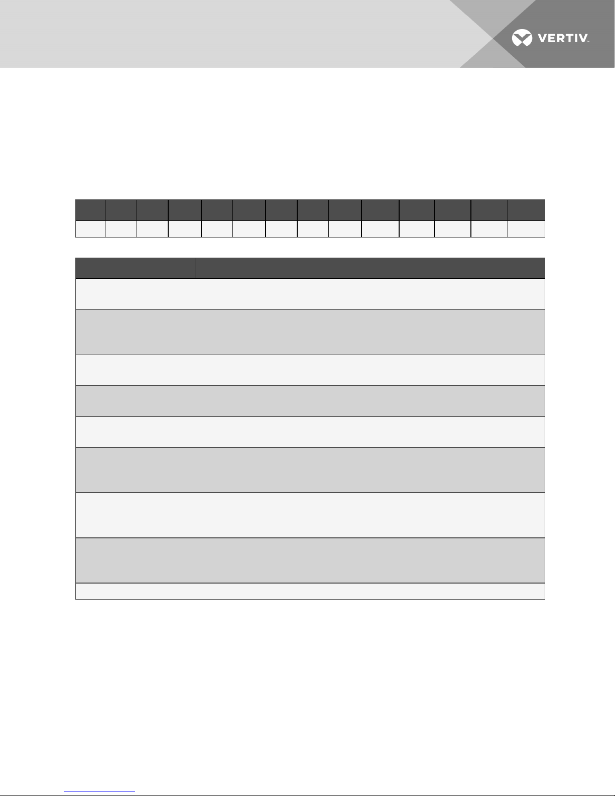
2.1 Liebert CW Model-number Nomenclature
Table 2.2 below describes each digit of the model number.
Table 2.1 CW Model Number
1 2 3 4 5 6 7 8 9 10 11 12 1 3 14
C W 0 2 6 D C S A 2 A X X X
Table 2.2 CW Model-number Digit Definitions
Digit Descript ion
Digits 1 and2 = Unit Family
CW = Liebert® CW floor-mounted, chilled-water unit
Digit 3, 4, 5 = Nominal Cooling Capacity, kW
340 = 340 kW
440 = 440kW
Digit 6 = Air Distribution
D = Downflow
Digit 7 = Cooling Type
C = Chilled water
Digit 8 = Fan Type
1 = EC fan
Digit 9 = Voltage
A = 460V - 3ph- 60Hz
B = 575V - 3ph - 60Hz
Digit 10 = Valve Type
2 = 2-way valve, standardpressure
1 = 2-way valve, high pressure
Digit 11 = Configuration Code
A-Z= Standard configuration
S = SFA
Digit 12, 13, 14= Factory configuration number
2 Nomenclature and Components 9
Page 10
2.2 Component Location
The unit component locations are described in the submittal documents included in the Submittal
Drawings on page37.
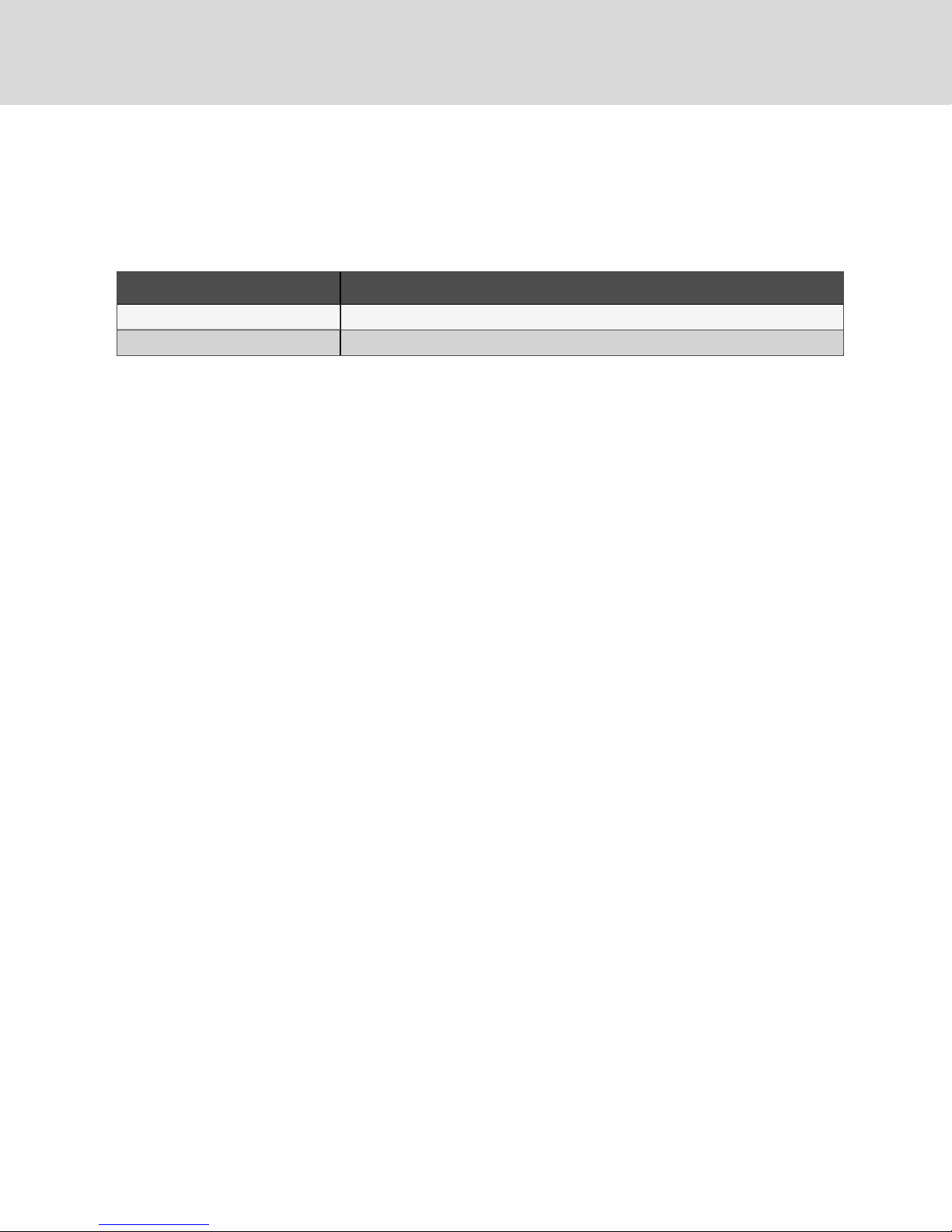
The following table lists the relevant documents by number and title.
Table 2.3 Component-location Drawings
Document Number Title
DPN003577 Component Location, CW340
DPN003574 Component Location, CW440
10
Vertiv | Liebert® CW™ Installer/UserGuide
Page 11
3 PLANNING GUIDELINES
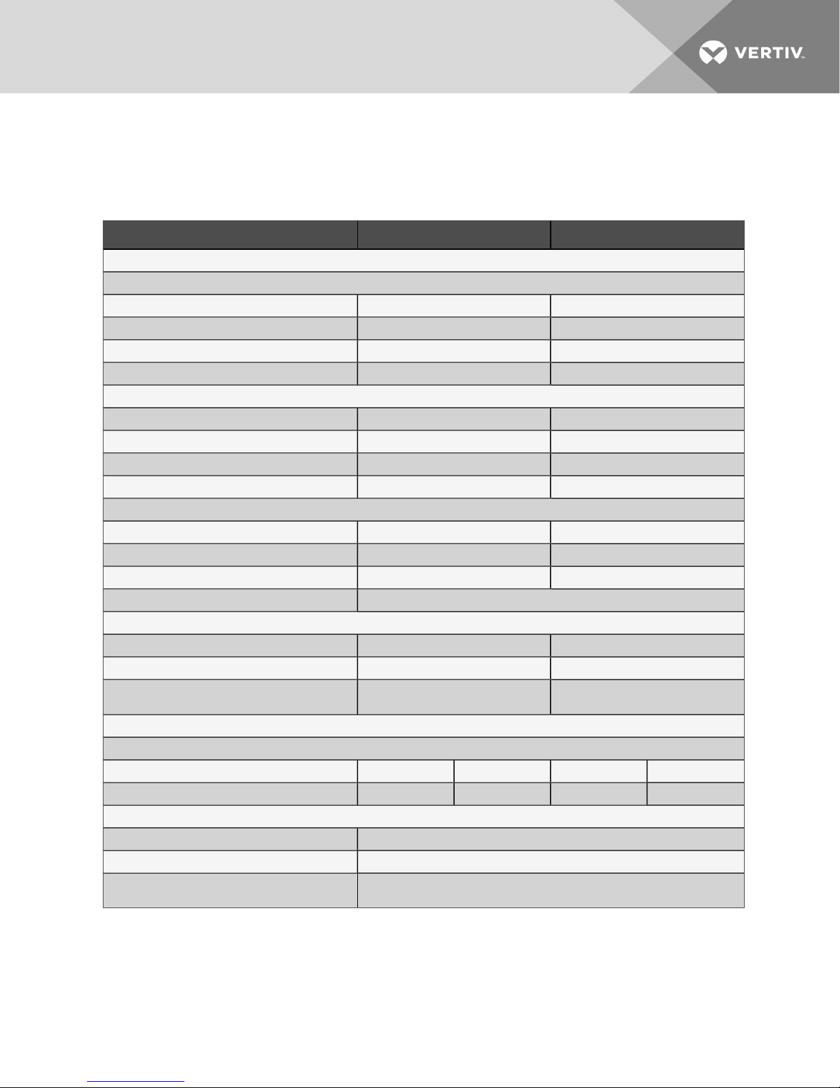
3.1 Capacity and Physical Data
Table 3.1 Performance data, Standard Chilled-water Unit withECfans
Model No. 340 440
NET CAPACITY DATA kBTU/H (kW) BASED ON 45°F (7.2°C) ENTERING WATER, 10°F (5.5°C) WATER RISE
75°F DB, 61°F WB (23.9°C DB , 16.1°C WB) 45% RH
Total Capacity, kBTUH (kW) 1410 (431) 1758 (515)
Sensible Capacity, kBTUH (kW) 1184(346) 1525 (447)
Flow Rate, GPM (l/s) 300 (18.9) 385 (24.29)
Pressure Drop, ft (kPA) 44 (130.7) 29 (87.3)
Fan Data - EC Fans - Available in Downflow Orientations
NominalAir Volume, CFM (CMH) 45,000 (76,455) 60,000 (101,941)
Fan Motor, Maximum hp (kW), each 16.1 (12.0) 16.1(12.0)
Standard Ext. Static Pressure, inches of water (PA) 0.3 (74.7) 0.3 (74.7)
Number of fans 3 4
Chilled Water Coil
Face Area, ft2(m2) 96 (8.91) 130 (12.08)
Number of Rows 6 6
Face Velocity, FPM(m/s) 470 (2.39) 460 (2.34)
Chilled Water Valves Maximum design water pressure 400PSI (2757 kPa)
Valve Actuator, Sensors and Body
Valve CV 70 130
Valve Size, in. 3.0 3.0
2-wayValve (optional)Close-off Pressure, PSI
(kPA)
Filter Section
Disposable Type - MERV8 (standard) or MERV11 (option)
NominalSizes, in. 20 x 24 x 4 18 x 24 x 4 20 x24 x 4 18 x 24 x 4
Quantity of each 18 9 22 11
Connection Sizes
Chilled Water (grooved, black pipe) 4 in.
Condensate Drain 2 x 1-1/4 in.
Condensate Discharge (when supplied with pump),
O.D.
100 (689) 100 (689)
1/2-in. compression
3 Planning Guidelines 11
Page 12
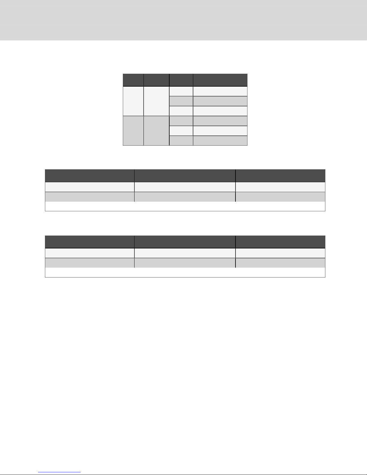
Table 3.2 Electrical data—with EC fans, 460
V/60 Hz
Model Qty. fans Voltage No reheat/No humidifier
FLA 46.5
CW340 3
CW440 4
WSA 50.4
OPD 60
FLA 62.0
WSA 65.9
OPD 80.0
3.2 Shipping Dimensions and Unit Weights
Table 3.3 Shipping Dimensions and weights for CW340
Model/Skid* Dimensions L x W x H, in. (mm) Weight, lb (kg)
Coil 190 x 70 x 87 (4826 x 1778x 2210) 4034 (1829)
Fan and Filter box 150 x 70 x 87 (3810 x 1778x 2210) 3027 (1373)
*Each system ships on two skids. Skid 1 is the coil section. Skid 2 isthe fan/filter-box sections.
Table 3.4 Shipping Dimensions and weights for CW440
Sections* Dimensions L x W x H, in. (mm) Weight, lb (kg)
Coil 190 x 70 x 87 (4826 x 1778x 2210) 4528 (2053)
Fan and Filter box 190 x 70 x 87 (4826 x 1778x 2210) 3896 (1767)
*Each system ships on two skids. Skid 1 is the coil section. Skid 2 isthe fan/filter-box sections.
12
Vertiv | Liebert® CW™ Installer/UserGuide
Page 13
3.3 Planning Dimensions
The unit, floor stand, and plenum dimensions are described in the submittal documents included in the
Submittal Drawings on page37.
The following table lists the relevant documents by number and title.
Table 3.5 Dimension Planning Drawings
Document Number Title
Downflow Units with EC Fans
DPN003561 Cabinet DimensionalData, CW340 with filter plenum
DPN003569 Cabinet DimensionalData, CW440 with filter plenum
Floor Stands for Units with EC Fans
DPN003964 Floorstand DimensionalData, Downflow Models, CW340
DPN003570 Floorstand D imensionalData, Downflow Models, CW440
3 Planning Guidelines 13
Page 14

Table 3.5 Dimension Planning Drawings (continued)
Document Number Title
Plenums for Units with EC Fans
DPN003964 Optionalrear-ducted EC fan sec tion for CW340
DPN003676 Optionalrear-ducted EC fan section for CW440
14
Vertiv | Liebert® CW™ Installer/UserGuide
Page 15

4 PRE-INSTALLATION PREPARATIONANDGUIDELINES
NOTE: Before installing unit, determine whether any building alterations are required to run piping,
wiring and ductwork. Follow all unit dimensional drawings and refer to the submittal engineering
dimensional drawings of individual units for proper clearances.
Refer to Table 2.2 on page9, and submittal drawings to determine the type of system being installed
and anticipate building alterations, piping and ductwork needed.
The unit dimensions, pipe-connection locations, and piping schematics are described in the submittal
documents included in the Submittal Drawings on page37.
• Verify that the floor is level, solid and sufficient to support the unit. See Table 3.3 on page12
for unit weights.
• Confirm that the room is properly insulated and has a sealed vapor barrier.
• For proper humidity control, keep outside or fresh air to an absolute minimum (less than 5% of
total air circulated in the room).
• Do not install a Liebert® CW in an alcove or at the end of a long, narrow room.
• Install the units as close as possible to the largest heat load.
• Allow at least the minimum recommended clearances for maintenance and service. See the
appropriate submittal drawings for dimensions.
• We recommend installing an under-floor water detection system. Contact your Vertiv
representative for information.
4.1 Site Preparation
Prepare the site for installation prior to arrival and unloading of the unit.
• If installing the unit on a concrete slab or housekeeping pad, sweep the concrete clean and
mark the final position of the unit(s) on the slab.
• Verify that all required clearances as specified by Vertiv are met.
• Mark the direction of the final unit placement to avoid accidental reversal of the unit.
• Protect stub-outs for electric conduit and any other projections against damage and clearly
mark their locations.
• Locate and mark the high point on the slab. This step is critical for the placement of multiple,
joined units.
• If installing on a structural-steel support structure, verify suitability of the supports beneath
the unit(s).
4.1.1 Preparing a Concrete Slab
1. Sweep the slab broom clean.
2. Lay out the final location of the unit on the slab, using either chalk line or tape, see Figure 4.1
on the next page.
3. Using a laser level or optical level, locate the high point on the slab and mark it, see Figure 4.1
on the next page.
4 Pre-installation PreparationandGuidelines 15
Page 16
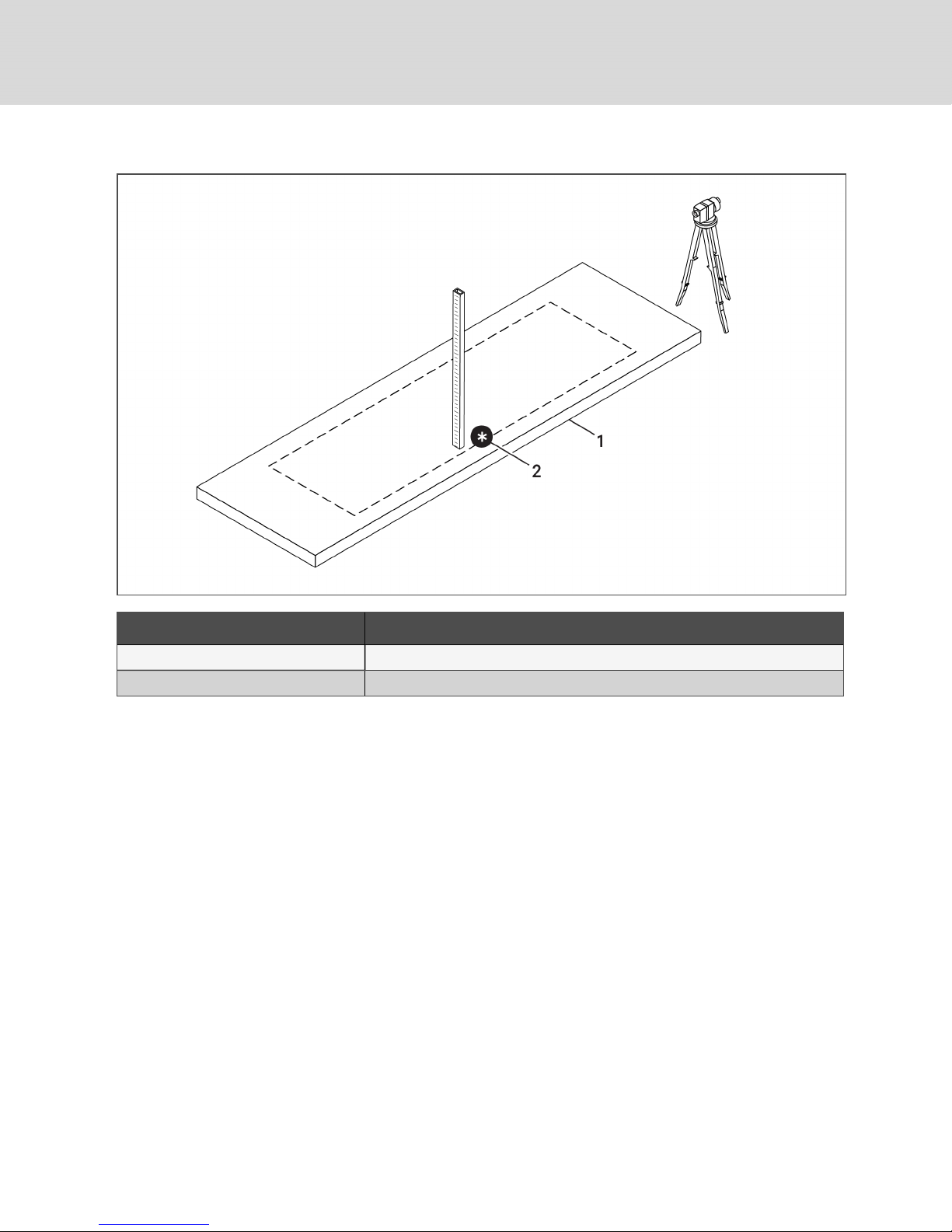
Figure 4.1 Unit and high-point marking on concrete slab
Item Description
1 Concrete slab
2 High point
16
Vertiv | Liebert® CW™ Installer/UserGuide
Page 17

5 EQUIPMENT INSPECTION AND HANDLING
SAFETY INFORMATION
WARNING! Risk of top-heavy unit falling over. Improper handling can cause equipment
damage, injury or death. Read all of the following instructions and verify that all lifting and
moving equipment is rated for the weight of the unit before attempting to move, lift, remove
packaging from or prepare the unit for installation. Unit weights are specified in Table 3.3 on
page12.
CAUTION: Risk of contact with sharp edges, splinters, and exposed fasteners. Can cause
injury. Only properly trained and qualified personnel wearing appropriate, OSHA-approved PPE
should attempt to move, lift, remove packaging from or prepare the unit for installation.
NOTICE
Risk of passageway interference. Can cause unit and/or structure damage. The unit may be
too large to fit through a passageway while on or off the skid. Measure the unit and passageway
dimensions, and refer to the installation plans prior to moving the unit to verify clearances.
NOTICE
Risk of damage from forklift. Can cause unit damage. Keep tines of the forklift level and at a
height suitable to fit below the skid and/or unit to prevent exterior and/or underside damage.
NOTICE
Risk of improper storage. Keep the unit upright, indoors and protected from dampness,
freezing temperatures and contact damage.
Upon arrival of the unit and before unpacking:
• Verify that the labeled equipment matches the bill of lading.
• Carefully inspect all items for visible or concealed damage.
• Report damage immediately to the carrier and file a damage claim with a copy sent to Vertiv or
to your sales representative.
• For initial access use a 7/32-in. Allen wrench for panel removal.
Equipment Recommended for Handling the Unit:
• Forklift
• Slings
• Spreader bars
5.1 Hardware Kit
The coil section of the unit ships with a hardware kit containing materials for reassembly of the unit
sections.
• 1-in. wide adhesive-backed foam (1/2-in. wide for seismic) for gasketing between unit sections
• 1-in. wide adhesive-backed foam for panel gasketing at the field-weld locations of sections
(seismic only)
5 EquipmentInspection and Handling 17
Page 18

5.2 Rigging
WARNING! Risk of improper lifting. Can cause equipment damage, injury, or death. A spreader
bar or equivalent must be used when rigging to ensure the lifting force is completely vertical at
these fasteners. Lift points are rated for lifting this section only. Do not lift assembled sections
from these lift points.
Vertiv does not provide rigging. Refer to the following for recommended rigging process.
• Use proper rigging equipment to make sure attachment and lifting at the designated lift points
is in the vertical direction. See Figure 5.2 on the facing page, and Figure 5.3 on page20, for
lift-point locations on the sections.
• All sections have four lift points to use rigging fasteners supplied.
• One rigging-fastener kit provided with fan and filter-section skid. See Figure 5.1 below, for
installation.
• Rigging fasteners are pre-installed on coil section, Figure 5.2 on the facing page.
NOTE: The rigging fastener kit provided with the fan and filter sections include additional hardware
and instructions for installation and use. See instructions included with the rigging-fastener kit. Refer
to Figure 6.2 on the next page for fastener location and lift points on the coil section.
Figure 5.1 Rigging-fastener installation
Item Description
1 Eye nut, 1/2-13 thread
2 Lock washer, 1/2-in.
3 Flat washer, 1/2-in.
4 1-in. x 1-in. tube
5 Screw, 1/2-13 x4 in.
18
Vertiv | Liebert® CW™ Installer/UserGuide
Page 19

Figure 5.2 Lift points on the coil section
Item Description
1 Coilsection
5 EquipmentInspection and Handling 19
Page 20

Figure 5.3 Lift points on filter-plenum, plenum extension, and fan sections
Item Description
1 Plenum extension
2 Filter plenum
3 Fan section
20
Vertiv | Liebert® CW™ Installer/UserGuide
Page 21

6 INSTALLING THE UNIT
Referring to Figure 6.1 on the next page, perform the following steps:
1. Referencing the highest point, set the fan section on marked location and level it with steel
shims.
2. Install additional steel shims, spaced not more than 6 ft apart.
3. Apply 1-in. (25-mm) wide [1/2-in (13 mm) wide on CW440 seismic installations] adhesivebacked foam (factory-supplied) to the inner-most edge of the mating surface of the bottom
section.
4. Once the section is in place, remove rigging fasteners (shown in Rigging on page18) before
stacking next section on top of lower section.
5. Swing the upper, split-unit section within 2 to 3 inches of the first section.
6. Make final adjustments to align the sections, and lower the upper section onto the section(s)
below.
7. Repeat steps 3 to 5 to place the filter and the (optional) plenum sections, see Figure 6.2 on
page23, for plenum placement.
6 Installingthe Unit 21
Page 22

Figure 6.1 Placing the unit and upper sections
Item Description
1 Connection locations
2 Bolt, 1/2-13 x 7.5in.
3 Flat washer, 1/2-in.
4 Lock nut, 1/2-13 thread
5 Steel shims under allliftingpoints
6 Established high point
7 Concrete slab or Housekeeping pad
8 Installfactory-supplied foam gasketing
22
Vertiv | Liebert® CW™ Installer/UserGuide
Page 23

Figure 6.2 Placing the (optional) plenum
Item Description
1 Connection locations
2 Bolt, 1/2-13 x 7.5in.
3 Flat washer, 1/2-in.
4 Lock nut, 1/2-13 thread
5 Installfactory-supplied foam gasketing
6 Optional, 18-in. decorative plenum
6.1 Connecting Unit Sections (Recommended)
Secure the coil-section frame to the fan-base frame and the filter-section frame to the coil-section frame.
8 locations on the CW340 or 10 locations on the CW440 are provided to connect the 3unit sections. If a
plenum option is included, 12locations on the CW340 or 14locations on the CW440 are provided.
The following is the factory-supplied hardware required (per location):
• Bolts 1/2 in. x 7.5 in.
• Nut hex, 1/2 in.
• (2) Flat washers, American National Standard Series W, type A, plain washers
6 Installingthe Unit 23
Page 24

6.2 Routing the Filter-clog Pick-up Tube in the Plenum
The pressure pick-up tube must be routed and mounted for proper operation of the filter-clog alarm. The
tube is factory-connected to the filter-clog switch in the low-voltage control box of the coil sections.
1. Locate the pick-up tube, which is coiled outside the low-voltage control box in the coil section.
2. Uncoil and route the tube into the filter plenum through the hole labeled "Filter Clog Sample
Tube" on the filter slide rail, see Figure 6.3 below.
Figure 6.3 Pressure tube routed from filter-clog switch into the filter plenum
Item Description
1 Filter-clog-sample-tube hole
2 Pressure pick-up tube
24
Vertiv | Liebert® CW™ Installer/UserGuide
Page 25

7 ELECTRICAL CONNECTIONS IN THE UNIT
WARNING! Arc flash and electric shock hazard. Open all local and remote electric power-supply
disconnect switches, verify with a voltmeter that power is Off and wear appropriate,
OSHA-approved personal protective equipment (PPE) per NFPA 70E before working within the
electric control enclosure. Failure to comply can cause serious injury or death. Customer must
provide earth ground to unit, per NEC, CEC and local codes, as applicable. Before proceeding
with installation, read all instructions, verify that all the parts are included and check the
nameplate to be sure the voltage matches available utility power. The Liebert® controller does
not isolate power from the unit, even in the “Unit Off” mode. Some internal components require
and receive power even during the “Unit Off” mode of the controller. The only way to ensure
that there is NO voltage inside the unit is to install and open a remote disconnect switch. Refer
to unit electrical schematic. Follow all local codes.
The electrical connections are described in the submittal documents included in the Submittal Drawings
on page37.
The following table lists the relevant documents by number and title.
Table 6.1 Electrical Field-connection Drawings
Document Number Title
DPN003601 ElectricalField Connections, D ownflow, CW340 and CW440
7.1 Fan High-voltage connections
Unshielded wiring is used for ON / OFF switching of the fans.
• Locate the high-voltage (AC power for fans) wires that are coiled and secured on top of the
lower section.
• Refer to the wire and fan numbers listed in the submittal drawing and 7.1 above, to connect
the wires from the lower section to the upper section of the unit.
• Use the quick-connect sockets located at the base of the coil section to connection to the
high-voltage panel.
7.2 Fan-control Low-voltage connections
Shielded wiring is used for analog-control of the fans.
• Locate the low-voltage (control wiring for fans) wires that are coiled and secured on top of the
lower section.
• Connect the wires from the lower section to the upper section of the unit, see Figure 6.4 on
the next page.
7 Electrical Connectionsin the Unit 25
Page 26

Figure 6.4 High- and Low-voltage connections in the fan section
Item Description
1 RS-485 connection
2 High-voltage connections. CW440 connec tions shown. CW340 has 3 quick-connect sockets.
26
Vertiv | Liebert® CW™ Installer/UserGuide
Page 27

7.3 Condensate-pump High- and Low-voltage Connections
The coil and fan sections are factory-wired with a quick-connect connector for the condensate pump.
After the coil section is lowered and secured to the fan section, connect the pump harness from the fan
section to the plug provided in the under-side of the coil section, see Figure 6.5 below.
Figure 6.5 Condensate-pump harness connection
Item Description
1 High-voltage power connection
2 Wire harness from EP
3 Low-voltage alarm connection
4 Condensate pump
5 Rear-side view
7 Electrical Connectionsin the Unit 27
Page 28

This page intentionally left blank
28
Vertiv | Liebert® CW™ Installer/UserGuide
Page 29

8 PIPING REQUIREMENTS
Factory-installed piping brackets must not be removed. Field-installed piping must be installed in
accordance with local codes and must be properly assembled, supported, isolated and insulated. Avoid
piping runs through noise-sensitive areas, such as office walls and conference rooms.
Refer to specific text and detailed diagrams in this manual for other unit-specific piping requirements.
All piping below the elevated floor must be located so that it offers the least resistance to air flow. Careful
planning of the piping layout under the raised floor is required to prevent the air flow from being blocked.
When installing piping on the subfloor, we recommend that the pipes be mounted in a horizontal plane
rather than stacked one above the other. Whenever possible, the pipes should be run parallel to the air
flow.
The pipe connection locations, piping general arrangement and schematics are described in the
submittal documents included in the Submittal Drawings on page37.
The following tables list the relevant documents by number and title.
Table 7.1 Piping Connection Drawings
Document Number Title
DPN003596 Piping Schematic, Downflow, CW340 and CW440
8.1 Installing Water Supply and Return Piping
We recommend installing an additional valve in a water-supply pipe to flush the system prior to start-up.
The additional valve may also provide water for periodic maintenance that includes cleaning the coils.
• Install all water-supply and water-return lines in accordance with industry best practices and
all local codes.
• The cooling water pipes are grooved to receive field-supplied, grooved pipe connectors.
• Follow the instructions provided by the manufacturer of the grooved pipe connectors for
correct installation and torque requirements of the assembly bolts.
8.2 Installing Drain Traps on a Unit without a Condensate Pump
Install field-fabricated drain traps at all trap locations on the unit. Drain traps are essential to allow water
to flow out of the drain pan(s). More importantly, when there is negative internal static within the unit, the
trap prevents outdoor air from being pulled into the unit and splashing water inside the unit. Drain-trap
design is dependent on the total static pressure (TSP). We recommend installing threaded plugs at
several locations to permit periodic cleaning and filling of the trap.
• See Figure 7.1 on the next page, for the location and number of traps.
• Drain-trap materials are installer-provided.
• Use industry best practices and follow all local codes when fabricating the traps.
• Figure 7.2 on the next page, shows a typical drain-trap design or, if a negative pressure trap is
needed, see Figure 7.3 on page31, and observe the following:
• Dimension “H” equals the Total Static Pressure in inches of water column plus a minimum
of one inch.
• The outlet side of the drain trap should have a water column equal to one-half of
dimension “H.”
• Use materials and fittings as local conditions dictate.
• Because the trap must be filled with water at all times, consider fabricating the trap from
metal so that an electric heat tape can be installed to prevent freezing.
8 PipingRequirements 29
Page 30

Figure 7.1 Drain-trap locations
Figure 7.2 Typical Drain-trap construction
Item Description
1 Condensate-discharge pipe from unit
2 Coupling (threaded socket)
3 Nipple
4 Cross
5 Threaded plugs (for clean-out)
6 Bend
7 Tee
8 Vacuum breaker
9 Sloped drain pipe
30
Vertiv | Liebert® CW™ Installer/UserGuide
Page 31

Figure 7.3 Negative-pressure drain-trap construction
Item Description
1 Condensate drain pan
2 Condensate-discharge pipe from unit/drain pan
3 One-half of dimension "H"
4 TotalStatic Pressure in inches of water column plus a minimum of one inch.
8.3 Installing Condensate-discharge Tubing on Units with a Condensate Pump
On units with a condensate pump, the factory-mounted pump requires field assembly to the two
condensate connections on the coil. After the unit is assembled, see Figure 7.4 on the next page, to
connect the piping to the pump. The pump-discharge connection is ½-in. copper compression. The
factory provides the compression a ring and nut for the discharge tube attached to the drain line into the
pump.
• Condensate pump (60 Hz): Condensate pump is rated for approximately 400 gph at 10 feet
total head.
• Condensate pump (50 Hz): Condensate pump is rated for approximately 315 gph at 10 feet
total head.
• Size the piping based on available condensate head.
• Condensate-pump discharge (drain) line must comply with all applicable codes.
8 PipingRequirements 31
Page 32

Figure 7.4 Field connections for the factory-piped condensate pump
Item Description
1 Connection locations
2 Condensate pump
8.4 Flushing the Entire Water System before Start-up
Both the pressurized water system and the drain system must be flushed before start-up:
• Flush all fresh-water lines before connecting to the cooling coils until the water runs clear and
all debris is flushed out.
• Flush again after the fresh-water lines are connected to the coils to clear any debris from the
cooling coils. Do not flush debris from the water lines into the coils.
• Thoroughly flush the drain system by running clean water through all drain pans and drain
lines, then visually inspect drain pans to verify that all debris is removed.
32
Vertiv | Liebert® CW™ Installer/UserGuide
Page 33

APPENDICES
Appendix A: Technical Support and Contacts
A.1 Technical Support/Service in the United States
Vertiv™ Corporation
24x7 dispatch of technicians for all products.
1-800-543-2378
Liebert® Thermal Management Products
1-800-543-2778
Liebert® Channel Products
1-800-222-5877
Liebert® AC and DC Power Products
1-800-543-2378
A.2 Locations
United States
Vertiv Headquarters
1050 Dearborn Drive
Columbus, OH, 43085, USA
Europe
Via Leonardo Da Vinci 8 Zona Industriale Tognana
35028 Piove Di Sacco (PD) Italy
Asia
7/F, Dah Sing Financial Centre
3108 Gloucester Road
Wanchai, Hong Kong
33
Page 34

This page intentionally left blank
34
Vertiv | Liebert® CW™ Installer/UserGuide
Page 35

Appendix B: Optional Configuration forLiebert®CW440Seismic Application
Electrical wiring, conduit, and/or other connections to the equipment is the responsibility of others. Data
and recommendations are supplied in the Submittal Drawings on page37,.
The following table lists the relevant documents by number and title.
Table B.1 Seismic-application Drawings
Document Number Title
DPN003636 Seismic Data for CW440D
35
Page 36

This page intentionally left blank
36
Vertiv | Liebert® CW™ Installer/UserGuide
Page 37

Appendix C: Submittal Drawings
The submittal drawings are in the order of document part number (DPN). Table C.1 below, groups the
drawings by topic/application.
Table C.1 Submittal-drawings Contents
Document Number Title
Component Location
DPN003577 Component Location, CW340
DPN003574 Component Location, CW440
Planning Dimensions - Downflow Units with EC Fans
DPN003561 Cabinet DimensionalData, CW340 with filter plenum
DPN003569 Cabinet DimensionalData, CW440 with filter plenum
Planning Dimensions - Floor Stands for Units with EC Fans
DPN003964 Floorstand DimensionalData, Downflow Models, CW340
DPN003570 Floorstand D imensionalData, Downflow Models, CW440
37
Page 38

Table C.1 Submittal-drawings Contents (continued)
Document Number Title
Planning Dimensions - Plenums for Units with EC Fans
DPN003964 Optionalrear-ducted EC fan sec tion for CW340
DPN003676 Optionalrear-ducted EC fan section for CW440
Piping Connections - Downflow Units with EC Fans
DPN003596 Piping Schematic, Downflow, CW340 and CW440
Electrical Connections - Downflow Units
DPN003601 ElectricalField Connections, D ownflow, CW340 and CW440
Seismic Anchorage Data
DPN003636 Seismic Data for CW440D
38
Vertiv | Liebert® CW™ Installer/UserGuide
Page 39

56"
Approximate Dry Weight
1422mm
OPENING
LIEBERT CW
CABINET DIMENSIONAL DATA
CW340 & FILTER PLENUM (plenum shipped separately)
122"
3099mm
OPENING
60"
1524mm
Note:
1. Filters are accessible
through front and top of unit
only.
2. Electrical connections
can be made from top
or bottom of unit.
102"
2591mm
TOTAL
HEIGHT
31"
788mm
FILTER
PLENUM
71"
1803mm
BASE
UNIT
1 9/16"
39mm
TYP.
TOP VIEW
138 3/4"
3525mm
FRONT VIEW
Base Unit
60"
1524mm
CW340
1 3/8"
35mm
HANDLE
Filter Plenum
(shipped separately)
Section lb. (kg)
Base Unit 3480 (1578)
Filter Plenum 595 (270)
DPN003561
Page :1 /1
Form No.: DPN001040_REV4
Striated area indicates the recommended
minimum clearance to be provided for
component access.
36"
914mm
Shaded area indicates the required minimum clearance
below the unit for the floorstands/fans to be installed.
REV : 3
REV DATE : 2/18
36"
914mm
Page 40

LIEBERT CW
Approximate Dry Weight
CABINET DIMENSIONAL DATA
56"
1422mm
OPENING
105 1/2"
2679mm
TOTAL
HEIGHT
34 1/2"
877mm
FILTER
PLENUM
CW440 & FILTER PLENUM (plenum shipped separately)
163"
4140mm
OPENING
Note:
1. Filters are accessible
through front and top of unit
only.
2. Electrical connections
can be made from top
or bottom of unit.
2 11/16"
69mm
TYP.
TOP VIEW
180"
4572mm
5/16"
8mm
BEZEL
58"
1473mm
1 5/16"
34mm
HANDLE
60"
1524mm
71"
1803mm
BASE
UNIT
Section lb. (kg)
Base Unit 3828 (1736)
Filter Plenum 742 (336)
FRONT VIEW
Striated area indicates the recommended
minimum clearance to be provided for
component access.
Shaded area indicates the required minimum clearance
below the unit for the floorstand/fans to be installed.
Base Unit
60"
1524mm
CW440
Filter Plenum
shipped separately
36"
914mm
36"
914mm
DPN003569
Page :1 /1
Form No.: DPN001040_REV4
REV : 3
REV DATE : 2/18
Page 41

LIEBERT CW
FAN SECTION DIMENSIONAL DATA
CW440 MODEL
Piping access area
(See Note 5)
43"
1092mm
TOP VIEW
180"
4572mm
38 1/4"
972mm
38 1/4"
972mm
38 1/4"
972mm
FRONT VIEW PANELS REMOVED FOR CLARITY
Attachment
Point
Attachment
Point
1"X1"X3" long steel tube
38 1/4"
972mm
Typ. (6) places
10"
254mm
Attachment
Point
PANELS REMOVED FOR CLARITY
60"
1524mm
OVERALL
RIGHT SIDE
BOTTOM VIEW
FANS REMOVED FOR CLARITY
Attachment
Point
Typ.
Attachment
Point
86"
2184mm
Typ.
10 1/2"
267mm
Typ.
Attachment
Point
NOTE:
1. This fan section is designed for 36" (914mm) raised floor height and can accomodate floors between 34" - 43" (864mm - 1092mm) high.
3. The fan section is not symmetrical and its orientation to the Liebert CW is critical for proper installation.
3. The EC fans must be field wired into connectors inside of the unit.
4. The EC fans are removed out the front of the fan section, and there must be clearance in front of fan section to be able to service fans (See DPN003569).
5. The fan section may be ordered with the piping access area at the opposite end, and the fans oriented accordingly.
73"
1854mm
DPN003570
Page :1 /1
Form No.: DPN001040_REV4
REV : 2
REV DATE : 1/17
Page 42

LIEBERT CW
COMPONENT LOCATION DIAGRAM
CW440
3
4
1
2
1. iCom Control Display
2. Electric Box
3. Filters
4. Coil
5. Disconnect
6. EC Fans
5
Note:
1. Unit with Plenum (shipped separately) attached shown
in order to provide view of filters.
2. Some panels removed from views for clarity.
6
DPN003574
Page :1 /1
Form No.: DPN001040_REV4
REV : 2
REV DATE : 1/17
Page 43

LIEBERT CW
COMPONENT LOCATION DIAGRAM
CW340
3
4
1
2
5
1. iCom Control Display
2. Electric Box
3. Filters
4. Coil
5. Disconnect
6. EC Fans
Note:
1. Unit with Plenum (shipped separately) attached shown
in order to provide view of filters.
2. Some panels removed from views for clarity.
DPN003577
Page :1 /1
Form No.: DPN001040_REV4
6
REV : 2
REV DATE : 1/17
Page 44

LIEBERT CW
POINT
DESCRIPTION
X in. (mm)
Y in. (mm)
CONNECTION SIZE/OPENING
Condensate Drain
1-1/4" NPT Female
(w/ optional pump)
1/2" O.D. Cu Hose Barb
Condensate Drain
1-1/4" NPT Female
(w/ optional pump)
1/2" O.D. Cu Hose Barb
CWS1
2-way Chilled Water Supply
51-1/4 (1302)
CWS2
2-way Chilled Water Supply
16-1/2 (419)
CWR1
2-way Chilled Water Return
19-3/8 (492)
CWR2
2-way Chilled Water Return
24-1/2 (622)
HV1
Electrical Connection (High Voltage)
5-5/16 (135)
HV2
Electrical Connection (High Voltage)
10-1/16 (256)
HV3
Electrical Connection (High Voltage)
10-1/4 (260)
HV4
Electrical Connection (High Voltage)
6-1/2 (165)
LV1
Electrical Connection (Low Voltage)
11-15/16 (303)
LV2
Electrical Connection (Low Voltage)
9-11/16 (246)
LV3
Electrical Connection (Low Voltage)
7-7/16 (189)
LV4
Electrical Connection (Low Voltage)
11-1/4 (286)
LV5
Electrical Connection (Low Voltage)
9-3/8 (238)
LV6
Electrical Connection (Low Voltage)
7-3/8 (187)
LV7
Electrical Connection (Low Voltage)
5-1/2 (140)
1-1/4" (32mm) [1-5/8" (41mm) /
PRIMARY CONNECTION LOCATIONS
CW340 & CW440
SECTION A-A
X
Top Piping Option Connection Locations
CWS1
CWR1
HV1
HV2
DETAIL A
LV1
LV2
LV3
LV4
LV5
HV3
CWS2
CWR2
DETAIL B
A
B
Y
0
SECTION B-B
X
Bottom Piping Option Connection Locations
CD1
SECTION C-C
Notes:
1 All views shown in standard configuration. CW340 & CW440 can be ordered with piping and
electrical connection locations located on left end of unit with fan sections adjusted as required.
LV7
2. If unit is ordered with Piping & Electrical Connection locations on the left side, then the callouts &
LV6
dimensions shown in this drawing will be reversed.
3. All "X" & "Y" dimensions are from front right corner of unit as shown. If unit is ordered with Piping &
HV4
Electrical Connections on left side, then dimensions are from front left corner.
4. Knockout diameters are concentric (see Detail A & B).
5. Field pitch Condensate Drain line a minimum of 1/8" (3.2mm) per 12" (305mm). All units with a
gravity drain require an external condensate trap. Select appropriate drain system materials.
The drain line must comply with all local codes.
CD2
Y
0
A
CD1
C
A
CD2
B
C
B
DPN003596
Page :1 /1
Form No.: DPN001040_REV4
5
2-5/16 (59)
5
7-1/2 (191)
11-9/16 (294)
11 (279)
49 (1245)
4-7/16 (113)
6-1/2 (166)
9-1/2 (242)
4" Grooved Pipe
2-1/8" (54mm)]
1-1/4" (32mm)
1-3/8" (35mm)
4
REV : 4
REV DATE : 3/18
Page 45

LIEBERT CW
n terminals
ELECTRICAL FIELD CONNECTION
DEFINITIONS AND LOCATIONS
CW340 & CW440 DOWNFLOW MODELS
STANDARD ELECTRICAL CONNECTIONS
1) Primary high voltage entrance - 2.50” (64mm); 1.75” (44mm) @ EP Box; 1.375” (35mm) diameter concentric knockouts located in
bottom of box
2) Primary low voltage entrance - Quantity (3) 1.375” (35mm) diameter knockouts located in bottom of box
3) Three phase electrical service - Terminals are on top of disconnect switch. Three phase service not by Liebert.
4) Earth ground - Terminal for field supplied earth grounding wire.
5) Remote unit shutdown - Replace existing jumper between terminals 37 & 38 with field supplied normally closed switch having a
minimum 75VA, 24VAC rating. Use field supplied Class 1 wiring.
6) Customer alarm inputs - Terminals for field supplied, normally open contacts, having a minimum 75VA, 24VAC rating, betwee
24 & 50, 51, 55, 56. Use field supplied Class 1 wiring. Terminal availability varies by unit options.
7) Common alarm - On any alarm, normally open dry contact is closed across terminals 75 & 76 for remote indication. 1 AMP, 24VAC max
load. Use Class 1 field supplied wiring.
8) Fan section RS485 connections – Quick connect socket located at the base of the coil section, below the low voltage panel provides
RS485 control for the fans. Requires field connection of fan section low voltage harness.
9) Fan section high voltage connections – Quick connect sockets located at the base of the coil section, below the high voltage panel
provide three phase power to the fans. Requires field connection of fan section high voltage harness.
OPTIONAL ELECTRICAL CONNECTIONS
10) Unit factory installed fused disconnect switch– Access to the high voltage electric panel compartment can be obtained only with the
switch in the “off” position.
11) Secondary disconnect switch and earth ground – Fuses are included in the 65KAIC SCCR fused disconnect switch models.
12) Smoke sensor alarm - Factory wired dry contacts from smoke sensor are 91-common, 92-NO, and 93-NC. Supervised contacts, 80 &
81, open on sensor trouble indication. This smoke sensor is not intended to function as, or replace, any room smoke detection system that
may be required by local or national codes. 1 AMP, 24VAC max load. Use Class 1 field supplied wiring.
13) Condensate alarm (with condensate pump option) - On pump high water indication, normally open dry contact is closed across terminals
88 & 89 for remote indication. 1 AMP, 24VAC max load. Use Class 1 field supplied wiring.
14) Remote Humidifier - On any call for humidification, normally open dry contact is closed across terminals 11 & 12 to signal field supplied
remote humidifier. 1AMP, 24VAC max load. Use Class 1 field supplied wiring.
15) Reversing Starter Power Supply Notification – Normally open contact terminals 102 and 103 will close when Power Supply 1 is
engaged; 106 and 107 will close when Power Supply 2 is engaged.
OPTIONAL LOW VOLTAGE TERMINAL PACKAGE CONNECTIONS
16) Remote unit shutdown - Two additional contact pairs available for unit shutdown (labeled as 37B & 38B, 37C & 38C). Replace jumpers
with field supplied normally closed switch having a minimum 75VA, 24VAC rating. Use field supplied Class 1 wiring.
17) Common alarm - On any alarm, two additional normally open dry contacts are closed across terminals 94 & 95 and 96 & 97 for remote
indication. 1 AMP, 24VAC max load. Use Class 1 field supplied wiring.
18) Main fan auxiliary switch - On closure of main fan contactor, normally open dry contact is closed across terminals 84 & 85 for remote
indication. 1 AMP, 24VAC max load. Use Class 1 field supplied wiring.
19) Liqui-Tect™ shutdown and dry contact - On Liqui-Tect™ activation, normally open dry contact is closed across terminals 58 & 59 for
remote indication (Liqui-Tect sensor ordered separately). 1 AMP, 24VAC max load. Use Class 1 field supplied wiring.
DPN003601
Page :1 /4
Form No.: DPN001040_REV4
REV : 3
REV DATE : 9/17
Page 46

LIEBERT CW
ELECTRICAL FIELD CONNECTION
DEFINITIONS AND LOCATIONS
CW340 & CW440 DOWNFLOW MODELS
High Temp
Stat
Filter Clog Switch
Air Safety Switch
Note: Typical orientation of components shown. Component location varies by option and unit.
RS485 Interface Board
Large iCOM™ Board
T6 Transformer
Condensate Pump
Alarm Relay
Intellislots
Smoke Detector
Power Supply
Condensate Pump fuses
2
Control fuses
Terminals for
Field Low Voltage
wiring connections
iCOM™ Fuse Board
Main Fan
fuses
A
B
C
D
T1 Transformer
4
3
1
10 Disconnect
Fan Contactors
15
107106103102
19
58
Note: Refer to Page 1 of 4 for descriptions of numbered callouts.
DPN003601
Page :2 /4
Form No.: DPN001040_REV4
18
17
12
8180939291
7
767597969594858459
A
B
6
13
14
12115655515024
16
5
383738B37B38C37C8988
C
D
FIELD TERMINAL LAYOUT
REV : 3
REV DATE : 9/17
Page 47

RS485 Interface Board
Large iCOM™ Board
LIEBERT CW
ELECTRICAL FIELD CONNECTION
DEFINITIONS AND LOCATIONS
CW340 & CW440 DOWNFLOW MODELS
Main Fan
fuses
Intellislots
Condensate Pump fuses
2
Control fuses
4
10
3
1
High Temp
Stat
Filter Clog Switch
Air Safety Switch
T6 Transformer
Note: Typical orientation of components shown. Component location varies by option and unit.
Condensate Pump
Alarm Relay
15
Smoke Detector
Power Supply
Terminals for
Field Low Voltage
wiring connections
iCOM™ Fuse Board
12
T1 Transformer
Fan Contactors
6
11
14
107106103102
19
58
Note: Refer to Page 1 of 4 for descriptions of numbered callouts.
DPN003601
Page :3 /4
Form No.: DPN001040_REV4
18
17
8180939291
7
767597969594858459
A
B
FIELD TERMINAL LAYOUT
12115655515024
13
16
5
383738B37B38C37C8988
REV : 3
REV DATE : 9/17
C
D
Page 48

8
Fan Section
RS485 Connection
LIEBERT CW
ELECTRICAL FIELD CONNECTION
DEFINITIONS AND LOCATIONS
CW340 & CW440 DOWNFLOW MODELS
Field Fan Section Connections
DPN003601
Page :4 /4
Form No.: DPN001040_REV4
Fan Section High Voltage
9
Connections (CW440 shown.
CW340 will have 3 quick
connect sockets)
REV : 3
REV DATE : 9/17
Page 49

LIEBERT CW
N
otes:
puted as
SEISMIC DATA
ANCHORAGE FOR CW440D
IMPORTANT SEISMIC REQUIREMENTS COMPLIANCE NOTE:
Values presented in this document are provided for unit anchorage sizing and do not imply compliance to IBC,
ASCE, or OSHPD seismic requirements. The Liebert CW440 has not been tested and certified. The anchorage
loads are provided as guidelines for the sizing of anchors for the attachment of the unit to the building structure
or housekeeping pad. Approval of all anchorage is subject to approval by the engineer of record for the project
or building.
1. The seismic overturn resistance anchorage load calculations provided for the Liebert CW440D computer room air handler are com
defined in the International Building Code (IBC) 2009, IBC 2012, and American Society of Civil Engineers (ASCE) Minimum Design Loads
for Buildings and Other Structures, ASCE 7-10.
2. The computer room air handler must be installed and attached to the building structure without spring isolators per the manufacturer
supplied installation instructions. The calculations exclude all non-factory supplied accessories. The unit base shall be bolted to
building/structure.
3. Mounting requirement details such as anchor brand, type, embedment depth, edge spacing, anchor-to-anchor spacing, concrete strength,
special inspection and attachment to non-building structures must be outlined and approved by the engineer of record for the project or
building. Structural floors and housekeeping pads must also be designed and approved by the project or building structural engineer of
record to withstand the seismic overturn anchor loads defined in the anchor table. The installing contractor is responsible for the proper
installation of all anchors and mounting hardware, observing the mounting requirements detailed in the installation drawings and
additionally outlined by the engineer of record.
4. Use flat washer, lock washer and nut to connect the Liebert CW440D. A minimum of 1/2" diameter anchors with American National
Standard Series W, type A, plain washers (ANSI B18.22.1-1965, R1975) selected to match the nominal anchor diameter must be installed
at each anchor location between the anchor head and equipment for tension load distribution.
DPN003636
Page :1 /3
Form No.: DPN001040_REV4
REV : 1
REV DATE : 2/17
Page 50

1"
25mm
Typ.
LIEBERT CW
SEISMIC DATA
ANCHORAGE FOR CW440D
178"
4521mm
62"
1575mm
1"
25mm
Typ.
A
A
Floor Anchoring Dimensions
Front of Unit
1 7/8"
48mm
Typ.
Notes:
1. Anchor Bolt sized per Hilti Kwik Bolt TZ Carbon and Stainless in Concrete, ICC ESR-1917.
Alternates are subject to review by Vertiv or Engineer of Record.
87 1/8"
2213mm
MIN. PAD
THICKNESS
2
SECTION A-A
3/4"
O
21mm
Anchor Holes
Typ. (6) Plcs
MIN. EMBEDMENT
EC Fans Removed
For Clarity
87 1/8"
2213mm
ANSI B18.22.1-1965(R2003)
TYPE A, SERIES W PLAIN
WASHER REQUIRED AT
EACH ANCHOR LOCATION
2
MIN. HOLE
DEPTH
2
2. Specified by Engineer of Record.
3. Operating mass includes the operating refrigerant, water volume, floor stand and plenum.
Operating mass*
Model No.
CW440 1/2" 6500 2948 3616 1640 1910 866 991 450
Sds=1.70, Rp=6, ap=2.5, Ip=1.5
Anchor
Size
3
Lbs kg Lbs kg Lbs kg Lbs kg
DPN003636
Page :2 /3
Form No.: DPN001040_REV4
Maximum
Compresssive
Reaction
Maximum Load per Anchor
Tension Shear
REV : 1
REV DATE : 2/17
Page 51

LIEBERT CW
Anchor
SEISMIC DATA
ANCHORAGE FOR CW440D
SECTION WELDING DIMENSIONS
FRAME TUBE
(OUTSIDE FACE)
GASKET
B
WELD
B
A
TYPICAL
(5mm)3/16
E
E
A
E
E
Welded Connection (Typ.)
E
E
E
Section B-B Filter to Coil Welds
C
C
D
Notes:
1. Gasket material is added to the inner most top mating edge of each section prior to stacking.
2. Weld materail must be designated for use in welding 304L Stainless Steel (308SS or equivalent).
3. Desocrative extension plenums to be bolted in (4) places.
Model No.
CW440 1/2" 3-1/2 (89) 6 (152) 2 (51)
DPN003636
Page :3 /3
Form No.: DPN001040_REV4
DIMENSIONAL DATA in. (mm)
Size
C D E
C
C
D D
Section A-A Coil to Fan Welds
REV : 1
REV DATE : 2/17
Page 52

LIEBERT CW
OPTIONAL DUCTED REAR CONNECTION
CW440 MODEL
Rear View
1 7/8"
48mm
1Piping Section
Notes:
1. Because Piping Section may appear at either end of unit
dimensions shown may be reversed depending on configuration
ordered.
DPN003676
Page :1 /1
Form No.: DPN001040_REV4
Fans Removed For Clarity
176 1/4"
4477mm
Top View
Rear View
1 3/4"
44mm
2 9/16"
65mm
27 5/16"
694mm
REV : 2
REV DATE : 10/18
Page 53

LIEBERT CW
FAN SECTION DIMENSIONAL DATA
3 FAN CW340 MODEL
Piping access area
(See Note 5)
43"
1092mm
Attachment
Point
TOP VIEW
138 11/16"
3523mm
38 1/4"
972mm
38 1/4"
972mm
38 1/4"
972mm
FRONT VIEW PANELS REMOVED FOR CLARITY
Attachment
Point
1"X1"X3" long steel tube
Typ. (6) places
10"
254mm
Attachment
Point
Attachment
Point
60"
1524mm
OVERALL
RIGHT SIDE
PANELS REMOVED FOR CLARITY
Attachment
Point
Attachment
Point
58 7/8"
1495mm
Typ.
BOTTOM VIEW
FANS REMOVED FOR CLARITY
NOTE:
1. This fan section is designed for 36" (914mm) raised floor height and can accomodate floors between 34" - 43" (864mm - 1092mm) high..
3. The fan section is not symmetrical and its orientation to the Liebert CW is critical for proper installation.
3. The EC fans must be field wired into connectors inside of the unit.
4. The EC fans are removed out the front of the fan section, and there must be clearance in front of fan section to be able to service fans (See DPN003561).
5. The fan section may be ordered with the piping access area at the opposite end, and the fans oriented accordingly.
DPN003964
Page :1 /1
Form No.: DPN001040_REV4
58 7/8"
1495mm
Typ.
10 1/2"
267mm
Typ.
REV : 1
REV DATE : 1/17
Page 54

Vertiv | Liebert® CW™ Installer/UserGuide
Page 55

VertivCo.com | Vertiv Headquarters, 1050 Dearborn Drive, Columbus, OH, 43085, USA
© 2018 Vertiv Co. Allrights reserved. Vertiv andthe Vertiv logo are trademarks or registered trademarks of Vertiv Co. Allother names and logos referred to
are trade names, trademarks or registered trademarks of their respec tive owners. While every precaution has been taken to ensure accuracy and
completeness herein, Vertiv Co. assumes no responsibility, and disclaims allliability, for damages resulting from use of this informationor for any errors or
omissions. Spec ifications are subject to change without notice.
SL-18062_REV4_9-18/590-1783-501C
 Loading...