

Page 1

Liebert® CRV Row
BasedCoolingSystem
Installer/User Guide
600 mm and 300 mm Wide
Page 2

Vertiv Liebert®CRV Installer/User Guide
The information contained in this document is subject to change without notice
and may not be suitable for all applications. While every precaution has been
taken to ensure the accuracy and completeness of this document, Vertiv
assumes no responsibility and disclaims all liability for damages result from
use of this information or for any errors or omissions.
Vertiv recommends installing a monitored fluid detection system that is wired
to activate the automatic closure of field-installed coolant fluid supply and
return shut off valves, where applicable, to reduce the amount of coolant fluid
leakage and consequential equipment and building damage. Refer to local
regulations and building codes relating to the application, installation, and
operation of this product. The consulting engineer, installer, and/or end user is
responsible for compliance with all applicable laws and regulations relation to
the application, installation, and operation of this product.
The products covered by this instruction manual are manufactured and/or sold
by Vertiv. This document is the property of Vertiv and contains confidential
and proprietary information owned by Vertiv. Any copying, use, or disclosure of
it without the written permission of Vertiv is strictly prohibited.
Names of companies and products are trademarks or registered trademarks of
the respective companies. Any questions regarding usage of trademark names
should be directed to the original manufacturer.
Technical Support Site
If you encounter any installation or operational issues with your product, check the pertinent section of this
manual to see if the issue can be resolved by following outlined procedures.
Visit https://www.vertiv.com/en-us/support/ for additional assistance.
Vertiv | Liebert ® CRV Installer/User Guide
Page 3

TABLE OF CONTENTS
1 Important Safety Instructions 1
2 Nomenclature and Components 7
2.1 Model Number Nomenclature 7
2.2 Component Location 7
2.3 Cooling Configurations and Liebert® CRV Overview 8
3 Pre-installation PreparationandGuidelines 9
3.1 Planning Dimensions 9
3.2 Unit Weights 9
4 Equipment Inspection and Handling 11
4.1 Packaging Material 12
4.2 Handling the Unit while Packaged 12
4.3 Unpacking the Export Shipped 600 mm(24 in.) Unit 12
4.4 Unpacking the Domestic Shipped 600 mm(24 in.) Unit 13
4.5 Removing 600 mm (24 in.) Units from the Pallet 14
4.6 Unpacking the Export Shipped 300 mm(24 in.) Unit 16
4.7 Unpacking the Domestic Shipped 300 mm(12 in.) Unit 17
4.8 Removing 300 mm (12 in.) Units from the Pallet 18
5 Installing in Enclosure Row 21
5.1 Adjusting Base Supports/Leveling Feet 21
5.2 Optional Tie Down Brackets for 300 mm (12 in.) Units 23
5.2.1 What’s Included 23
5.2.2 Tools Required 24
5.2.3 Installing Tie Down Brackets on300 mm(12 in.) andonCabinetsofDifferentHeights 24
5.2.4 Installing Tie Down Brackets on300 mm(12 in.) andonCabinetsoftheSameHeight 26
6 Piping and Refrigerant Requirements 27
6.1 Drain and Humidifier Fluid Piping 28
6.1.1 Humidifier Water Supply Line Requirements 28
6.1.2 Condensate Pump Drain Line Requirements 29
6.1.3 Condensate Pump Drain Piping for300 mm(12 in.) Models 30
6.1.4 FieldInstalled, Gravity Fed Drain Line Requirements 36
6.2 Refrigerant Piping and Charging 41
6.2.1 Refrigerant Piping Guidelines forAir CooledSystems 42
6.3 Piping Guidelines for Liebert® MC Condensers 43
6.3.1 Piping Layout and Condenser Positioning 44
6.3.2 Top or Bottom Connection for Refrigerant Piping onAir Cooled Units 45
6.3.3 Refrigerant Line Sizes and Equivalent Lengths 46
6.3.4 Refrigerant Charge Requirements for Air Cooled Systems 47
6.3.5 Additional Oil Requirements for Digital ScrollCompressors 50
6.3.6 Evacuation, Leak Testing, and Charging Air Cooled Systems without Receivers 52
Vertiv™ | Liebert® CRV Installer/User Guide | i
Page 4

6.3.7 Evacuation, Leak Testing, and Charging Air Cooled Systems withLiebert® Lee-Temp Flooded Condenser
Head PressureControlSystem 56
6.3.8 Superheat and Refrigerant Charge Optimization 58
6.4 Water/Glycol Loop Piping Guidelines 59
6.4.1 Glycol Mixture 62
6.4.2 Water/Glycol Cooled Piping Connections 62
6.4.3 Leak Checking for Unit and Field Installed Piping 64
6.5 Chilled Water Loop Piping 64
7 Electrical Connections 67
7.1 Power Supply Cable Connection Guidelines 67
7.2 Wiring Connection Guidelines 67
7.3 Electrical Field Connections Descriptions 68
7.3.1 Locating the Serial Tags and Removing the Electrical Panel on 600mm (24 in.) Units 68
7.3.2 Cable Entry Points on 600mm (24in.) Units 71
7.3.3 Protective Features of Electrical Heaters—600-mm (24-in.) Units 72
7.3.4 Accessing the Electrical Panel on 300 mm (12 in) Units 72
7.3.5 Releasing the Electric Panel Lock 73
7.4 Protective Features of the Electronically Commutated (EC) Fans—All Models 74
8 Humidifier 600 mm (24 in.) Units Only 77
8.1 Principal of Operation 77
8.2 Connecting Water Supply to the Humidifier 78
8.3 Humidifier Startup and Operation 79
8.3.1 Low Water Conductivity 79
8.4 Humidifier Canister Replacement 79
8.4.1 Removing the Old Canister 80
8.4.2 Mandatory Cleaning of the Drain Valve 81
8.4.3 Installing the New Canister 82
8.5 Humidifier Maintenance during Extended Shutdown 83
8.5.1 Humidifier Troubleshooting 83
8.5.2 Humidifier Troubleshooting Steps 85
9 Startup 87
9.1 Checks to Perform after Startup 88
9.2 Automatic Restart 89
9.3 Chilled Water Valve— All Chilled Water Models 90
9.4 Adjust Baffles to Direct Air Properly 91
9.4.1 Adjusting Baffles—600mm (24in.) 92
9.4.2 Adjusting Blocker Plate—600mm (12in.) 93
9.4.3 Adjusting Baffles—300mm (12 in.) 94
10 Troubleshooting 97
11 Maintenance 101
11.1 Safety Instructions 101
11.2 Facility Fluid and Piping Maintenance forWaterandGlycolSystems 102
Vertiv™ | Liebert® CRV Installer/User Guide | ii
Page 5

11.3 Glycol Solution Maintenance 102
11.4 Spare Parts 102
11.5 Maintenance Schedule 102
11.6 Thermostatic Expansion Valve (TXV) Maintenance 104
11.6.1 Determining Suction Superheat 104
11.6.2 Adjusting Superheat Setting with the TXV 105
11.7 Compressor Maintenance 105
11.7.1 Compressor Oil 105
11.7.2 Replacement Compressors 105
11.7.3 Rotalock Valve on Digital Scroll Compressors 106
11.7.4 Unloading Solenoid(s) on a Digital Scroll Compressor 106
11.7.5 Compressor Electrical Failure (Motor Burnout) 107
11.7.6 Compressor Mechanical Failure 107
11.7.7 Replacing a Compressor with Mechanical Failure 107
11.8 Inspect and Replace the Air Filters—600 mm (24in.) Models 108
11.9 Inspect and Replace the Air Filters—300mm (12in.) Models 110
11.10 Condensate Drain and Condensate Pump System Maintenance 111
11.10.1 Condensate Drain 111
11.10.2 Condensate Pump, Dual Float 111
11.11 Air-Cooled Condenser and Drycooler Maintenance 112
11.12 Electric Reheat Maintenance 112
11.13 Fan Replacement 113
11.13.1 Replacing a Fan in 600mm (24in.) Models 113
11.13.2 Replacing a Fan in 300mm (12in.) Models 114
11.14 Considerations when Dismantling the Unit 115
11.15 F-Gas Regulation (EC) No. 842/2006 116
12 Preventive Maintenance Worksheet 119
Appendices 125
Appendix A: Technical Support and Contacts 125
Appendix B: Model Number Nomenclature Detail 127
Appendix C: Submittal Drawings 131
Vertiv™ | Liebert® CRV Installer/User Guide | iii
Page 6

Vertiv™ | Liebert® CRV Installer/User Guide | iv
Page 7

Vertiv Liebert®CRV Installer/User Guide
1 Important Safety Instructions
SAVE THESE INSTRUCTIONS
This manual contains important safety instructions that should be followed during the installation and maintenance of the
Liebert® CRV. Read this manual thoroughly before attempting to install or operate this unit.
Only qualified personnel should move, install or service this equipment.
Adhere to all warnings, cautions, notices and installation, operating and safety instructions on the unit and in this manual.
Follow all installation, operation and maintenance instructions and all applicable national and local building, electrical and
plumbing codes.
Any operation that requires opening doors or equipment panels must be carried out only by properly-trained and qualified
personnel.
To identify the unit model and serial number for assistance or spare parts, locate the identification label on the unit. The
label is inside the door on 600 mm (24 in.) units and at the electrical box on 300 mm (12 in.) units.
A warning label on the front and back panels reminds users that:
• The Liebert® CRV restarts automatically
• The main switch must be opened before opening the internal compartments for any operation.
WARNING! Arc flash and electric shock hazard. Open all local and remote electric power-supply disconnect
switches, verify with a voltmeter that power is Off and wear appropriate, OSHA-approved personal protective
equipment (PPE) per NFPA 70E before working within the electric control enclosure. Failure to comply can
cause serious injury or death. Customer must provide earth ground to unit, per NEC, CEC and local codes, as
applicable. Before proceeding with installation, read all instructions, verify that all the parts are included and
check the nameplate to be sure the voltage matches available utility power. The Liebert® controller does not
isolate power from the unit, even in the “Unit Off” mode. Some internal components require and receive
power even during the “Unit Off” mode of the controller. The only way to ensure that there is NO voltage
inside the unit is to install and open a remote disconnect switch. Refer to unit electrical schematic. Follow all
local codes.
Installation, service, and maintenance work must be performed only by properly trained and qualified
personnel and in accordance with applicable regulations and manufacturers’ specifications. Opening or
removing the covers to any equipment may expose personnel to lethal voltages within the unit even when it is
apparently not operating and the input wiring is disconnected from the electrical source.
WARNING! Risk of over pressurization of the refrigeration system. Can cause explosive discharge of high
pressure refrigerant, loss of refrigerant, environmental pollution, equipment damage, injury, or death. This
unit contains fluids and gases under high pressure. Use extreme caution when charging the refrigerant
system. Do not pressurize the system higher than the design pressure marked on the unit's nameplate.
1 Importan t Safety Inst ructions
1
Page 8

Vertiv Liebert®CRV Installer/User Guide
WARNING! Risk of contact with high speed rotating fan blades. Can cause serious injury or death. Open all
local and remote electric power-supply disconnect switches, verify with a voltmeter that power is off, and
verify that all fan blades have stopped rotating before working in the unit cabinet or on the fan assembly. Fan
motor controls can maintain an electric charge for 10 minutes after power is disconnected. If control voltage
is applied, the fan motor can restart without warning after a power failure.
WARNING! Risk of top-heavy unit falling over. Improper handling can cause equipment damage, injury or
death. Read all of the following instructions and verify that all lifting and moving equipment is rated for the
weight of the unit before attempting to move, lift, remove packaging from or prepare the unit for installation.
Unit weights are specified in Table 3.2 on page9
WARNING! Risk of unsecured unit rolling off pallet. Can cause equipment damage, injury or death. The unit is
on casters. Ensure that the pallet is located on a flat surface before loosening the hardware securing the to
its shipping pallet.
WARNING! Risk of hair, clothing and jewelry entanglement with high speed rotating fan blades. Can cause
equipment damage, serious injury or death. Keep hair, jewelry and loose clothing secured and away from
rotating fan blades during unit operation.
WARNING! Risk of contact with extremely hot and/or cold surfaces. Can cause injury. Verify that all
components have reached a temperature that is safe for human contact or wear appropriate, OSHA-approved
PPE before working within the electric connection enclosures or unit cabinet. Perform maintenance only
when the system is de-energized and component temperatures have become safe for human contact.
WARNING! Risk of improper wiring, piping, moving, lifting and handling. Can cause equipment damage,
serious injury or death. Installation and service of this equipment should be done only by qualified personnel
who have been specially trained in the installation of air conditioning equipment and who are wearing
appropriate, OSHA-approved PPE.
WARNING! Risk of improper wire sizing/rating and loose electrical connections. Can cause overheated wire
and electrical connection terminals resulting in smoke, fire, equipment and building damage, injury or death.
Use correctly sized copper wire only and verify that all electrical connections are tight before turning power
On. Check all electrical connections periodically and tighten as necessary.
WARNING! Risk of humidifier canister meltdown, smoke and fire. Can cause fire suppression system
activation, fire and smoke alarm activation, building evacuation, dispatching of fire and rescue equipment
and personnel and water leaks resulting in expensive equipment or building damage, injury or death. Check
steam generating humidifier electrode plugs to ensure that they are pressed firmly onto pins. Loose
connections will cause overheating of cylinder and plugs.
2
1 Importan t Safety Inst ructions
Page 9

Vertiv Liebert®CRV Installer/User Guide
CAUTION: Risk of contact with sharp edges, splinters, and exposed fasteners. Can cause injury. Only
properly trained and qualified personnel wearing appropriate, OSHA-approved PPE should attempt to move,
lift, remove packaging from or prepare the unit for installation.
CAUTION: Risk of improper moving, lifting and handling. Can cause equipment damage or injury. Only
properly trained and qualified personnel should work on this equipment. Condenser fan modules weigh in
excess of 125 lb (56.7 kg). Use proper lifting techniques and wear appropriate, OSHA-approved PPE to avoid
injury and dropping the fan module during removal. Equipment used in handling/lifting, and/or installing the
fan assembly must meet OSHA requirements. Use handling/lifting equipment rated for the weight of the fan
assembly. Use ladders rated for the weight of the fan assembly and technicians if used during installation.
Refer to handling/lifting, and/or installation equipment operating manual for manufacturer's safety
requirements and operating procedures.
CAUTION: Risk of exposure to harmful noise levels. Can cause hearing injury or loss. Depending on the
installation and operating conditions, a sound pressure level greater than 70dB(A) may arise. Take
appropriate technical safety measures. Operating personnel must wear appropriate, OSHA-approved PPE
and observe all appropriate hearing protection safety requirements.
NOTICE
NOTICE
CAUTION: Risk of excessive refrigerant line pressure. Can cause tubing and component rupture resulting in
equipment damage and personal injury. Do not close off the refrigerant line isolation valve for repairs unless
a pressure-relief valve is field installed in the line between the isolation valve and the check valve. The
pressure relief valve must be rated 5% to 10% higher than the system design pressure. An increase in
ambient temperature can cause the pressure of the isolated refrigerant to rise and exceed the system design
pressure rating (marked on the unit nameplate).
Risk of improper power supply connection. Can cause equipment damage and loss of warranty coverage.Prior
to connecting any equipment to a main or alternate power source (for example: backup generator systems) for
startup, commissioning, testing, or normal operation, ensure that these sources are correctly adjusted to the
nameplate voltage and frequency of all equipment to be connected. In general, power source voltages should
be stabilized and regulated to within ±10% of the load nameplate nominal voltage. Also, ensure that no three
phase sources are single phased at any time.
Risk of oil contamination with water. Can cause equipment damage.
Liebert® CRV systems require the use of POE (polyolester) oil. POE oil absorbs water at a much faster rate
when exposed to air than previously used oils. Because water is the enemy of a reliable refrigeration system,
extreme care must be used when opening systems during installation or service. If water is absorbed into the
POE oil, it will not be easily removed and will not be removed through the normal evacuation process. If the oil
is too wet, it may require an oil change. POE oils also have a property that makes them act as a solvent in a
refrigeration system. Maintaining system cleanliness is extremely important because the oil will tend to bring
any foreign matter back to the compressor.
1 Importan t Safety Inst ructions
3
Page 10

Vertiv Liebert®CRV Installer/User Guide
NOTICE
Risk of improper refrigerant charging. Can cause equipment damage.
Refrigerant charge must be weighed into air-cooled compressorized systems before they are started. Starting
scroll and digital scroll compressors without proper refrigerant charging can cause the compressors to operate
at less than 5°F (–15°C) evaporator temperature and at less than 20psig (138kPa). Operation for extended
periods at less than 20psig (138kPa) can cause premature compressor failure.
NOTICE
Risk of clogged or leaking drain lines and leaking water supply lines. Can cause equipment and building
damage.
This unit requires a water drain connection. Drain lines must be inspected at startup and periodically, and
maintenance must be performed to ensure that drain water runs freely through the drain system and that lines
are clear and free of obstructions and in good condition with no visible sign of damage or leaks. This unit may
also require an external water supply to operate.
Improper installation, application and service practices can result in water leakage from the unit. Water
leakage can result in catastrophic and expensive building and equipment damage and loss of critical data
center equipment.
NOTICE
Do not locate unit directly above any equipment that could sustain water damage.
We recommend installing a monitored fluid detection system to immediately discover and report coolant fluid
system and condensate drain line leaks.
Risk of piping system corrosion and freezing fluids. Can cause leaks resulting in equipment and very expensive
building damage. Cooling coils, heat exchangers and piping systems are at high risk of freezing and premature
corrosion. Fluids in these systems must contain the proper antifreeze and inhibitors to prevent freezing and
premature coil, heat exchanger and piping corrosion. The water or water/glycol solution must be analyzed by a
competent local water treatment specialist before start up to establish the inhibitor and antifreeze solution
requirement and at regularly scheduled intervals throughout the life of the system to determine the pattern of
inhibitor depletion.
The complexity of water/glycol solution condition problems and the variations of required treatment programs
make it extremely important to obtain the advice of a competent and experienced water treatment specialist
and follow a regularly scheduled coolant fluid system maintenance program.
Water chemistry varies greatly by location, as do the required additives, called inhibitors, that reduce the
corrosive effect of the fluids on the piping systems and components. The chemistry of the water used must be
considered, because water from some sources may contain corrosive elements that reduce the effectiveness of
the inhibited formulation. Sediment deposits prevent the formation of a protective oxide layer on the inside of
the coolant system components and piping. The water/coolant fluid must be treated and circulating through
the system continuously to prevent the buildup of sediment deposits and or growth of sulfate reducing
bacteria.
Proper inhibitor maintenance must be performed in order to prevent corrosion of the system. Consult glycol
manufacturer for testing and maintenance of inhibitors.
4
1 Importan t Safety Inst ructions
Page 11

NOTICE
NOTICE
Vertiv Liebert®CRV Installer/User Guide
Commercial ethylene glycol, when pure, is generally less corrosive to the common metals of construction than
water itself. It will, however, assume the corrosivity of the water from which it is prepared and may become
increasingly corrosive with use if not properly inhibited.
We recommend installing a monitored fluid detection system that is wired to activate the automatic closure of
field installed coolant fluid supply and return shutoff valves to reduce the amount of coolant-fluid leakage and
consequential equipment and building damage. The shutoff valves must be sized to close off against the
maximum coolant fluid system pressure in case of a catastrophic fluid leak.
Risk of frozen pipes and corrosion from improper coolant mixture. Can cause water leaks resulting in
equipment and building damage.
When the cooling unit or piping may be exposed to freezing temperatures, charge the system with the proper
percentage of glycol and water for the coldest design ambient temperature. Automotive antifreeze is
unacceptable and must NOT be used in any glycol fluid system. Use only HVAC glycol solution that meets the
requirements of recommended industry practices.
NOTICE
NOTICE
NOTICE
Risk of no flow condition. Can cause equipment damage.
Do not leave the water/coolant fluid supply circuit in a no flow condition. Idle fluid allows the collection of
sediment that prevents the formation of a protective oxide layer on the inside of tubes. Keep unit switched On
and water/coolant fluid-supply circuit system operating continuously.
Risk of doorway/hallway interference. Can cause unit and/or structure damage. The unit may be too large to fit
through a doorway or hallway while on the skid. Measure the unit and passageway dimensions, and refer to the
installation plans prior to moving the unit to verify clearances.
Risk of improper water supply. Can reduce humidifier efficiency or obstruct humidifier plumbing.
Do not use completely demineralized water with this unit. The water must contain minerals for the electrode
principle to work.
Do not use a hot water source. It will cause deposits that will eventually block the fill valve opening.
Risk of water backing up in the drain line. Leaking and overflowing water can cause equipment and building
damage.
Do not install an external trap in the drain line. This line already has a factory installed trap inside the cabinet
(except for 300 mm (12 in.)) Chilled water models). Installation of a second trap will prevent drain water flow
and will cause the water to overflow the drain pan.
1 Importan t Safety Inst ructions
This line may contain boiling water. Use cooper or other material that is rated for handling boiling water for the
drain line. Sagging condensate drain lines may inadvertently create an external trap.
5
Page 12

Vertiv Liebert®CRV Installer/User Guide
NOTICE
Risk of doorway/hallway interference. Can cause unit and/or structure damage. The unit may be too large to fit
through a doorway or hallway while on the skid. Measure the unit and passageway dimensions, and refer to the
installation plans prior to moving the unit to verify clearances.
NOTICE
Risk of damage from forklift. Can cause unit damage. Keep tines of the forklift level and at a height suitable to
fit below the skid and/or unit to prevent exterior and/or underside damage.
NOTICE
Risk of improper storage. Can cause unit damage.
Keep the unit upright, indoors and protected from dampness, freezing temperatures and contact damage.
NOTICE
Risk of release of hazardous substances into the environment. Can cause environmental pollution and violation
of environmental regulations.
The Liebert® CRV contains substances and components hazardous for the environment (electronic
components, refrigerating gases and oils). At the end of its useful life, the Liebert® CRV must be dismantled by
specialized refrigerating technicians. The unit must be delivered to suitable centers specializing in the
collection and disposal of equipment containing hazardous substances.
NOTE: The Liebert indoor cooling unit has a factory installed high pressure safety switch in the high side refrigerant
circuit. Consult local building codes to determine whether the Liebert® MC Condensers without receivers will require
field provided pressure relief devices such as a fusible plug. A pressure relief valve is provided with Liebert® LeeTemp receivers.
Agency Listed
Standard 60 Hz units are CSA Certified to the harmonized U.S. and Canadian product safety standard CSA C22.2 No
236/UL 1995 for “Heating and Cooling Equipment” and are marked with the CSA c-us logo.
6
1 Importan t Safety Inst ructions
Page 13
Vertiv Liebert®CRV Installer/User Guide
2 Nomenclature and Components
This section describes the model number for Liebert® CRV units and components.
2.1 Model Number Nomenclature
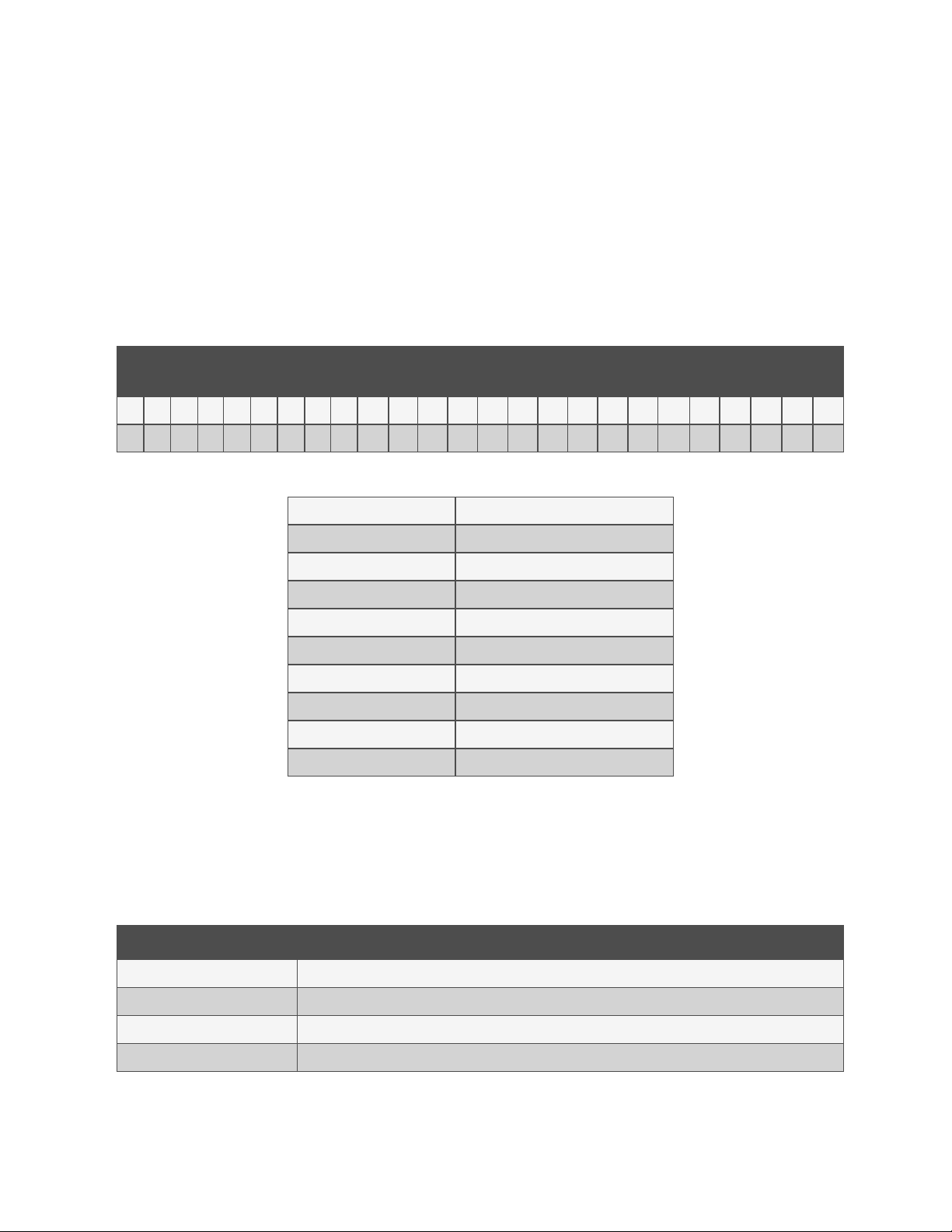
The tables describe the 25 digitconfigurationnumber. The 14 digit model number consists of the first 10 digits and last 4
digits of the configuration number.
For the full description of configuration and model number refer to Model Number Nomenclature Detail on page127 .
Model Number D igits 1 to 10 Model Details
1 2 3 4 5 6 7 8 9 1 0 11 12 13 14 15 16 17 18 19 20 21 22 23 24 25
C R 0 2 0 R A 1 C 7 S H 1 8 1 1 E L 1 0 P A — — —
Digits 1 -2 - Unit Fam ily Digit14 - Air Filter
Digits 3-5 - Nominal Capacity, kW Digit 15 - Water/Glycol Valve Type
Digit6 - Row-Based, Unit Depth Digit 16 - Enclosure
Digit7 - System Type Digit17 - High Voltage Options
Digit8 - Fan Type Digit18 - Option Package
Digit9 - Power Supply Digit19 - Liebert® IntelliSlot™ Housing
Digit10 - Cooling System Digit20 - Future Options
Digit11 - Humidifier Digit21 - Packaging With Ra mp
Digit12 - Control System Digit22 - Special Features
Digit13 - Reheat Digits 23-25 - Factory Configuration Number
Model Number D igits 11
to 14
2.2 Component Location
The unit component locations are described in the submittal documents included in the Submittal Drawings on page131 .
The following table lists the relevant documents by number and title.
Table 2.1 Component Location Drawings
Docu ment Number Title
DPN003738 Component Location Diagram, 600mm (24in.) Models
DPN003583 Component Location Diagram, 30 0mm (12in.) Air Cooled Models
DPN003585 Component Location, 300mm (12in.) Water Glycol Cooled Models
DPN003584 Component Location, 300mm (12in.) Chilled Water Models
2 N omenclature an d Components
7
Page 14
Vertiv Liebert®CRV Installer/User Guide
2.3 Cooling Configurations and Liebert® CRV Overview
The Liebert®CRV is a precision cooling unit available in compressorized (air, water, or glycol cooled) and chilled water
configurations to be installed within a row of high density computing racks in a “hotaisle-coldaisle” configuration.
Air enters the rear of the CRV from the hot aisle, is filtered, cooled and conditioned, then discharged into the cold aisle. The
CRV provides all the necessary functions of a standard Thermal Management unit, including cooling, heating,
humidification, dehumidification, air filtration, condensate management, temperature control, alarm monitoring and data
communication. (The 300 mm [12 in.] models do not provide heating, humidification or dehumidification.) The CRV is
optimized for maximum cooling capacity in a minimal footprint.
The Liebert® CRV 300 series and 600 series Thermal Management units are meant for location within a row of heat
generating IT equipment racks.
The extremely energy efficient components of the CRV are managed by the Liebert® iCOM™ control system. The iCOM
control monitors the environment in real time with rack inlet sensors on the cooled by the in-row CRV. The information
gathered allows optimization of performance and energy efficiency.
All operations and sensor data can be reported remotely via a variety of communication protocols, providing a built-in,
rack-temperature monitoring system.
The supply-air baffle directs the air leaving the CRV to the racks, maximizing its effectiveness, reducing the chance for hot
spots, and improving overall system efficiency. The angle and spacing of the baffle vanes series are optimized through CFD
modeling, laboratory testing and real world installations.
All service and maintenance is performed through the front and rear of the unit, including all component replacement. All
piping and electrical connections are made through the top or bottom of the unit.
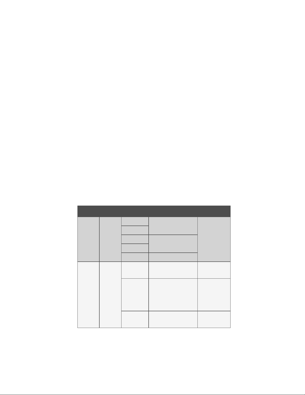
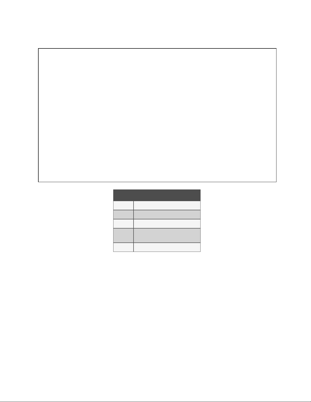
Table 2.2 CRV Configurations
Series Width C oo ling Type Nom inal C oo ling Capacity, kW Input Power 60 Hz
600
300
24 in.
(600 m m)
12 in.
(300 mm)
Air
Water/Glycol
Air
Water/Glycol
Chilled Water 40
Air 19
Chilled Water 32
20
35
208 V/3 ph
460 V/3 ph
208-230 V/3 ph
460 V/3 ph-Wye
208-230 V/1 ph
208-230 V/3 ph
460 V/3 ph-Wye
120 V/1 ph
Water/Glycol 19
8
208-230 V/3 ph
460 V/3 ph-Wye
2 N omenclature an d Components
Page 15
Vertiv Liebert®CRV Installer/User Guide
3 Pre-installation PreparationandGuidelines
NOTE: Before installing unit, determine whether any building alterations are required to run piping, wiring and duct
work. Follow all unit dimensional drawings and refer to the submittal engineering dimensional drawings of individual
units for proper clearances.
Refer to Model Number Nomenclature on page7 and the appropriate submittal drawings, to determine the type of system
being installed and anticipate building alterations, piping and duct work needed.
The unit dimensions, pipe connection locations, and piping schematics are described in the submittal documents included
in the Submittal Drawings on page131 .
• Verify that the floor is level, solid and sufficient to support the unit. See Unit Weights below for unit weights.
• Confirm that the room is properly insulated and has a sealed vapor barrier.
• For proper humidity control, keep outside or fresh air to an absolute minimum (less than 5% of total air
circulated in the room).
• Do not install a Liebert® CRV in an alcove or at the end of a long, narrow room.
• Install the units as close as possible to the largest heat load.
• Allow at least the minimum recommended clearances for maintenance and service. See the appropriate
submittal drawings for dimensions.
• We recommend installing an under floor leak detection system. Contact your Vertiv representative for
information.
3.1 Planning Dimensions
The unit, floor stand, and plenum dimensions are described in the submittal documents included in the Submittal Drawings
on page131 .
The following table lists the relevant documents by number and title.
Table 3.1 Dimension Planning Drawings
Docu ment Number Title
DPN001791 Cabinet Dimensional Data 600 m m (24 in.) Models
DPN002807 Cabinet Dimensional Data 300 mm (12 in,) Models
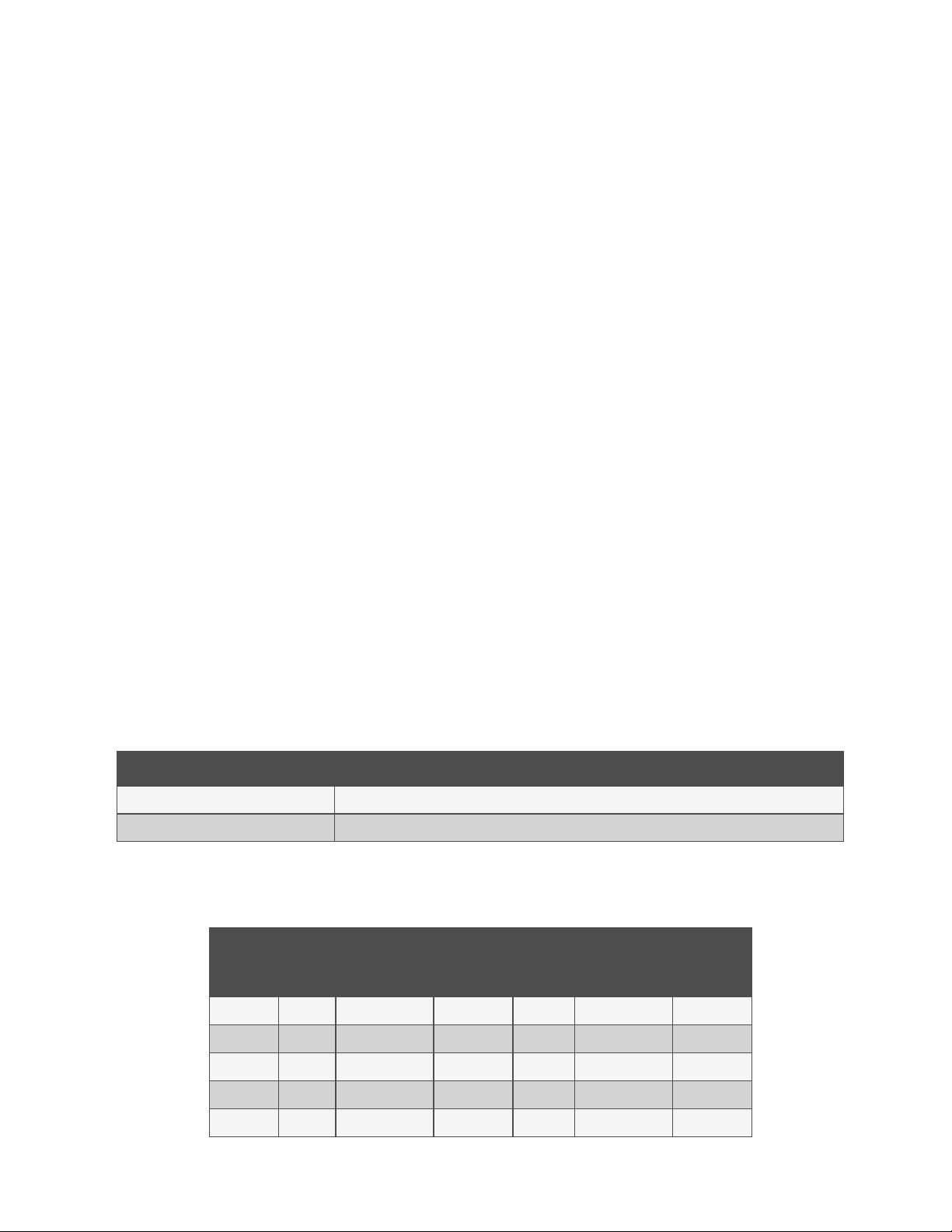
3.2 Unit Weights
Table 3.2 Shipping Weights
Dom estic Packaging, lb (kg) Export Packaging, lb (kg)
Model No .
Air Water/Glycol Chilled Water Air Water/Glycol Chilled Water
CR019 649(294) 687 (311) — 721 (327) 782 (355) —
CR032 — — 560 (254.0) — — 683 (309.8)
CR020 846 (384) 879 (399) — 953 (432) 986 (447) —
CR035 912 (414) 956 (434) — 1019 (462) 1063 (482) —
CR040 — — 835 (379) — — 942 (427)
3 Pre-installation Prep arationand Guidelin es
9
Page 16

Vertiv Liebert®CRV Installer/User Guide
This page intentionally left blank
10
3 Pre-installation Prep arationand Guidelin es
Page 17

4 Equipment Inspection and Handling
WARNING! Risk of top-heavy unit falling over. Improper handling can cause equipment damage, injury or
death. Read all of the following instructions and verify that all lifting and moving equipment is rated for the
weight of the unit before attempting to move, lift, remove packaging from or prepare the unit for installation.
Unit weights are specified in Table 3.2 on page9
WARNING! Risk of contact with sharp edges, splinters, and exposed fasteners. Can cause injury. Only
properly trained and qualified personnel wearing appropriate, OSHA-approved PPE should attempt to move,
lift, remove packaging from or prepare the unit for installation.
NOTICE
Risk of passageway interference. Can cause unit and/or structure damage. The unit may be too large to fit
through a passageway while on or off the skid. Measure the unit and passageway dimensions, and refer to the
installation plans prior to moving the unit to verify clearances.
Vertiv Liebert®CRV Installer/User Guide
NOTICE
Risk of damage from forklift. Can cause unit damage. Keep tines of the forklift level and at a height suitable to
fit below the skid and/or unit to prevent exterior and/or underside damage.
NOTICE
Risk of improper storage. Can cause unit damage.Keep the unit upright, indoors and protected from dampness,
freezing temperatures and contact damage.
Upon arrival of the unit and before unpacking:
• Verify that the labeled equipment matches the bill of lading.
• Carefully inspect all items for visible or concealed damage.
• Report damage immediately to the carrier and file a damage claim with a copy sent to Vertiv or to your sales
representative.
• For initial access, use a 7/32 in. Allen wrench for panel removal.
Equipment Recommended for Handling the Unit:
• Forklift
• Pallet jack
• Piano jacks
• Slings
• Spreader bars
4 Equipment Insp ection and Handl ing
11
Page 18

Vertiv Liebert®CRV Installer/User Guide
4.1 Packaging Material
All material used to package this unit is recyclable. Please save for future use or dispose of the material appropriately.
4.2 Handling the Unit while Packaged
Transport the unit with a forklift or pallet jack.
When using a forklift or pallet jack:
• Make sure that the forks (if adjustable) are spread to the widest allowable distance that will fit under the skid.
• Make sure the fork length is suitable for the skid length. Skid length is 60in (1524mm)
• When moving the packaged unit, do not lift the unit any higher than 2to4in. (51to102 mm). All personnel
except those moving the unit must be kept 12ft (3.7m) or more from the unit while it is being moved.
• If the unit must be lifted higher than 4in. (102 mm), all personnel not directly involved in moving the unit must
be 20ft (5m) or farther from the unit.
4.3 Unpacking the Export Shipped 600 mm(24 in.) Unit
1. Remove the metal clips (12 places typical) that secure the top panel of the crate to the side panels, see Figure
4.1 on the facing page .
2. Use a Phillips head screw driver to remove all the wood screws (34 places typical) that secure the side panels
together and to the pallet, see Figure 4.1 on the facing page .
3. To remove the remaining packaging, start with Step 1 , of Unpacking the Domestic Shipped 600 mm(24 in.)
Unit on the facing page .
12
4 Equipment Insp ection and Handl ing
Page 19
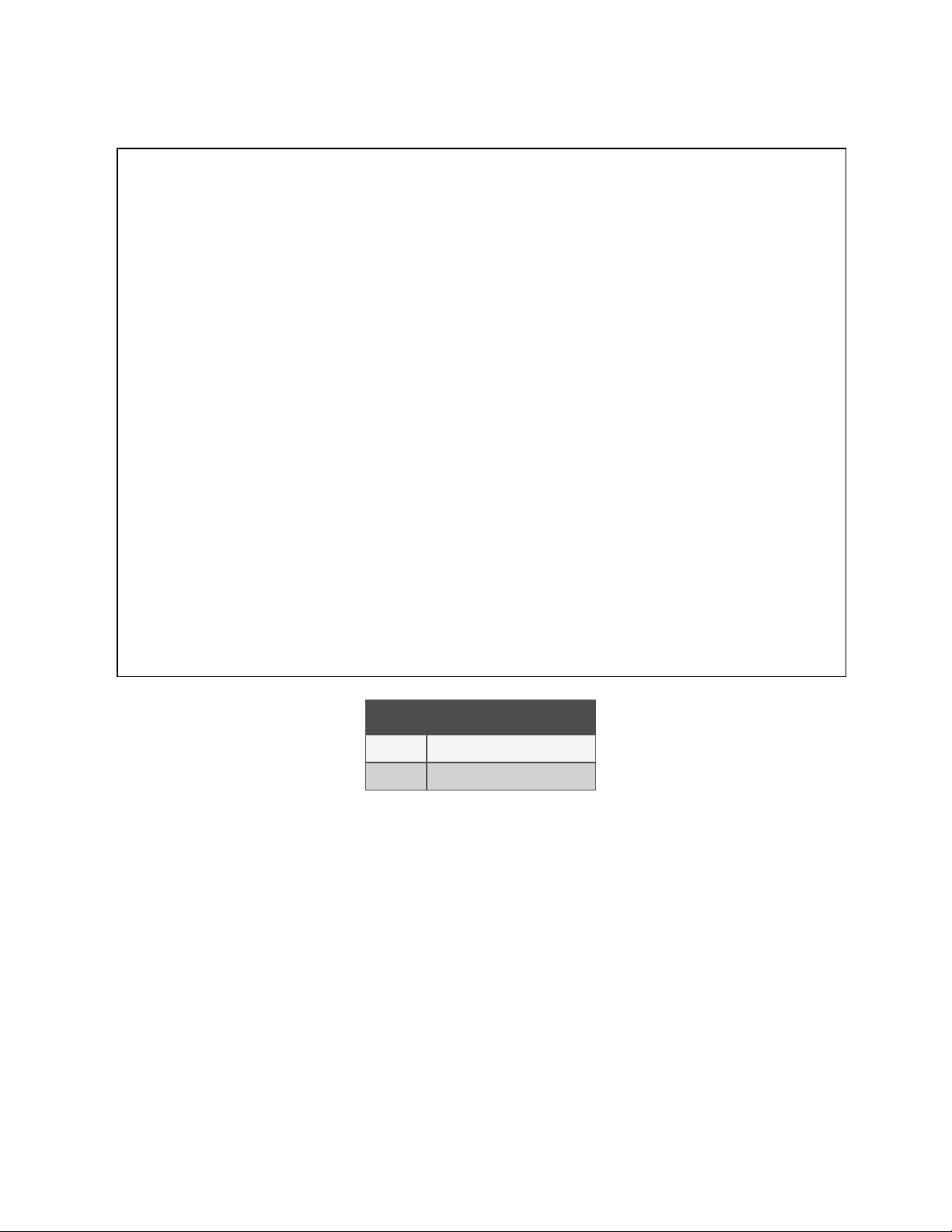
Figure 4.1 Metal Clips and Wood Screws on Crate
Vertiv Liebert®CRV Installer/User Guide
Item Description
1 Metal clips, typical 12 places
2 Wood screws, m inimum 34 places
4.4 Unpacking the Domestic Shipped 600 mm(24 in.) Unit
1. Use a 9/16 in. socket drive or wrench to remove the lag screws (4 places typical) that secure the ramp to the
pallet, see Figure 4.2 on the next page . Set the ramps aside for use later when preparing move the unit from
the pallet.
2. Remove the exterior packaging from around the unit
NOTE: The bag may remain in place to protect from dust and to protect the unit panels, or it may be removed for
immediate installation.
3. Remove the bag from the unit when ready to move off the pallet and install the unit. See Removing 600 mm
(24 in.) Units from the Pallet on the next page .
4 Equipment Insp ection and Handl ing
13
Page 20
Vertiv Liebert®CRV Installer/User Guide
Figure 4.2 Lag Screws that Secure Ramps
4.5 Removing 600 mm (24 in.) Units from the Pallet
1. Remove front panel, see Figure 4.3 on the facing page
• Open the top panel door (with controller display).
• Using a 8 mm hex head or T30 Torx screwdriver, remove the screws securing the bottom front panel
assembly, and set aside until instructed to re attach.
• Close and latch the top panel door.
2. Lower the 4 leveling feed to touch the pallet deck as shown in Figure 4.3 on the facing page . Open the rear,
hinged door to access the rear leveling feet.
3. Using a 13 mm socket-drive or wrench, remove the screws that secure the shipping brackets to the side of the
unit, 3 each side, see Figure 4.3 on the facing page .
4. Using a 9/16 in. socket drive or wrench, remove the lag screws that secure the shipping brackets to the pallet, 4
each side, see Figure 4.3 on the facing page .
5. Adjust the 4 leveling feet equally, to raise the unit off the shipping blocks, and remove the blocks, see Figure
4.3 on the facing page .
14
4 Equipment Insp ection and Handl ing
Page 21
Figure 4.3 Preparing to Attach Ramps
Vertiv Liebert®CRV Installer/User Guide
Item Description
1 Leveling feet touching pallet, front view
2 13 mm hex head screw, 3 ea ch side
3 9/16-in. hex head screw, 4 each side
4 Leveling feet raise unit off shipping blocks, front view
6. Locate the ramps and attach to the pallet using the hook and loop strips, see Figure 4.4 on the next page , for
placement of the strips.
WARNING! Risk of unsecured unit rolling off pallet. Can cause equipment damage, injury or death. The unit is
on casters. Ensure that the pallet is located on a flat surface before loosening the hardware securing the to
its shipping pallet.
7. Adjust the 4 leveling feet equally until casters make contact with the pallets, then continue to raise all the feet
to the full up position, see Figure 4.4 on the next page .
IMPORTANT! Two or more properly trained and qualified personnel are required to move the unit to its installation
location.
8. With two or more personnel, move the unit from the pallet, to the ramps, to the floor, and then to the installation
location.
4 Equipment Insp ection and Handl ing
15
Page 22
Vertiv Liebert®CRV Installer/User Guide
Figure 4.4 Ramps Attached and Leveling Feet Raised
Item Description
1 Leveling feet fully raised. Casters ready to roll.
4.6 Unpacking the Export Shipped 300 mm(24 in.) Unit
1. Remove the metal clips (12 places typical) that secure the top panel of the crate to the side panels, see Figure
4.5 on the facing page .
2. Use a Phillips-head screw driver to remove all the wood screws (34 places typical) that secure the side panels
together and to the pallet, see Figure 4.5 on the facing page .
3. To remove the remaining packaging, start with Step 1 , of Unpacking the Domestic Shipped 300 mm(12 in.)
Unit on the facing page .
16
4 Equipment Insp ection and Handl ing
Page 23

Figure 4.5 Metal Clips and Wood Screws on Crate
Vertiv Liebert®CRV Installer/User Guide
4.7 Unpacking the Domestic Shipped 300 mm(12 in.) Unit
1. Use a 9/16 in. socket drive or wrench to remove the lag screws (4 places typical) that secure the ramp to the
pallet, see Figure 4.6 on the next page . Set the ramps aside for use later when preparing move the unit from
the pallet.
2. Remove the exterior packaging from around the unit
NOTE: The bag may remain in place to protect from dust and to protect the unit panels, or it may be removed for
immediate installation.
3. Remove the bag from the unit when ready to move off the pallet and install the unit. See Removing 300 mm (12
in.) Units from the Pallet on the next page .
4 Equipment Insp ection and Handl ing
17
Page 24
Vertiv Liebert®CRV Installer/User Guide
Figure 4.6 Lag Screws that Secure Ramps
4.8 Removing 300 mm (12 in.) Units from the Pallet
1. Locate the ramps and attach to the pallet using the hook and loop strips, see Figure 4.7 on the facing page ,
for placement of the strips.
WARNING! Risk of unsecured unit rolling off pallet. Can cause equipment damage, injury or death. The unit is
on casters. Ensure that the pallet is located on a flat surface before loosening the hardware securing the to
its shipping pallet.
2. Using a 13-mm socket-drive or wrench, remove the screws that secure the shipping brackets to the side of the
unit, 3 each side, see Figure 4.7 on the facing page .
3. Using a 9/16-in. socket-drive or wrench, remove the lag screws that secure the shipping brackets to the pallet,
3 each side, see Figure 4.7 on the facing page .
IMPORTANT! Two or more properly-trained and qualified personnel are required to move the unit to its installation
location.
4. With two or more personnel, move the unit from the pallet, to the ramps, to the floor, and then to the installation
location.
18
4 Equipment Insp ection and Handl ing
Page 25
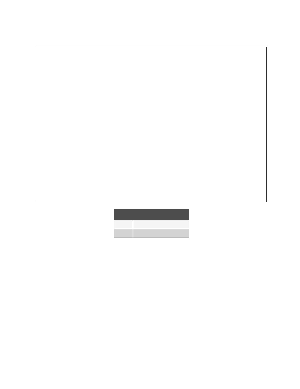
Figure 4.7 Attach Ramps and Remove Shipping Brackets
Vertiv Liebert®CRV Installer/User Guide
Item Description
1 13 mm hex-head screw, 3 ea ch side
2 9-16 in. hex-head screw, 3 ea ch side
4 Equipment Insp ection and Handl ing
19
Page 26

Vertiv Liebert®CRV Installer/User Guide
This page intentionally left blank
20
4 Equipment Insp ection and Handl ing
Page 27

Vertiv Liebert®CRV Installer/User Guide
5 Installing in Enclosure Row
Built-in casters let you roll the Liebert® CRV into position for installation. For 300 mm units, optional stabilizers reduce the
likelihood of the module tipping over. These stabilizers, shown in Figure 5.1 on the next page , must be removed before the
unit is positioned in the row. Adjustable leveling feet prevent it from moving after positioning, See Adjusting Base
Supports/Leveling Feet below .
Once positioned, secure the unit to the floor or to an adjacent cabinet.
Adjustable brackets for attaching the unit to an adjacent cabinet are included with each unit. A bracket to attach the unit to
the floor is available from your Vertiv representative.
5.1 Adjusting Base Supports/Leveling Feet
1. After the unit is in its final installation position, open the display door and remove the lower front baffle panel
using a 10 mm nut driver or T30 Torx Bit to prepare for installation.
2. Open the rear panel.
3. Using an adjustable wrench, adjust the four base supports, or feet, shown in Figure 5.1 on the next page .
Ensure that the unit is level to avoid corrosion or health hazards caused by condensate accumulation.
4. Turning the base supports (leveling feet) clockwise, extends them, and lifts the unit one corner at a time.
5. Tighten the nut on the top of each foot to lock the feet. The nut on 600 mm (24 in.) units is inside the cabinet.
The nut on 300 mm (24 in.) units is under the cabinet, as shown in Figure 5.2 on page23 .
5 In stalling in Enclosure Row
21
Page 28
Vertiv Liebert®CRV Installer/User Guide
Figure 5.1 Caster Locations
Item Description
1 Rear of 300 mm (12 in.) unit, bottom view
2 Rear of 600 mm (24 in.) unit, bottom view
3 Caster, 1 at each corner
4
Stabilizer (optional), 1 at ea ch corner.
Only available for 300 mm (12 in.) units.
5 Adjustable leveling foot, 1 at ea ch corner
22
5 In stalling in Enclosure Row
Page 29
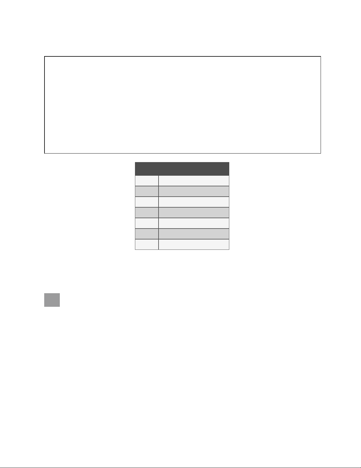
Figure 5.2 Adjust Leveling Feet
Vertiv Liebert®CRV Installer/User Guide
Item Description
1 600 mm (24 in.) unit
2 300 mm (12 in.) unit
3 Nut on top of foot.
4 Adjust foot with wrench
5 Adjust foot with wrench
6 Jam nut, secures foot and final height
7 Nut to raise/lower foot.
5.2 Optional Tie Down Brackets for 300 mm (12 in.) Units
An optional tie down bracket may be installed on the unit to secure it in the row. The bracket keeps the space between the
cooling unit and adjacent equipment constant, preventing noise from vibration.
WARNING! Risk of electric shock and/or improper drilling. Can cause equipment damage, injury or death.
Open all local and remote electric power disconnect switches, verify that power is off with a voltmeter and
verify that no servers or other equipment is located in the intended area for drilling or use of mounting
screws. Verify that there are no electric wires or equipment that may be damaged by the drill or by the
resulting shavings and debris.
5.2.1 What’s Included
5 In stalling in Enclosure Row
• Brackets: 4 (2 piece, L-shaped components; for cabinets of different heights)
• Bracket tie-downs: 2 (flat brackets; for cabinets of same height)
• M6 bolts: 2
• M6 nuts: 2
• Washers: 2
• Self-tapping screws: 16
23
Page 30

Vertiv Liebert®CRV Installer/User Guide
5.2.2 Tools Required
• Screwdriver, Phillips #2 Bit
• Drill
• Drill bit: 1/8” diameter
• 10 mm wrench or adjustable wrench
5.2.3 Installing Tie Down Brackets on300 mm(12 in.)
andonCabinetsofDifferentHeights
To install the tie down bracket:
1. Insert the M6 bolt through the longest slot in the two-piece tie-down bracket as shown in Figure 5.3 on the
facing page .
2. Secure the tie-down bracket loosely with the washer and M6 nut.
3. Position the tie-down bracket over the factory fabricated holes on the top of the Liebert® CRV and over the top
of the adjacent cabinet as shown in Tie Down Bracket on Cabinets of Different Heights—300mm (12 in.) on the
facing page .
4. Mark where the self-tapping screws will attach the tie down bracket to the adjacent cabinet.
5. Taking proper precautions to collect the metal shavings and protect equipment, drill holes in the adjacent
cabinet for the two screws.
6. Use a vacuum cleaner or other method to remove all metal particles.
7. Position the bracket over the holes in the Liebert® CRV and the adjacent cabinet.
8. Insert and tighten the four screws.
9. Tighten the M6 nut installed in step 2 securely.
24
5 In stalling in Enclosure Row
Page 31

Figure 5.3 Tie Down Bracket on Cabinets of Different Heights—300mm (12 in.)
Vertiv Liebert®CRV Installer/User Guide
Item Description
1 Top of a djacent cabinet
2 Rear of unit
3 Top of unit
4 Screw holes for tie-down brackets
5 Front of unit
6 Screws in drilled holes.
5 In stalling in Enclosure Row
25
Page 32

Vertiv Liebert®CRV Installer/User Guide
5.2.4 Installing Tie Down Brackets on300 mm(12 in.)
andonCabinetsoftheSameHeight
To install the tie down bracket:
1. Position the tie-down bracket over the factory fabricated holes on the top of the Liebert® CRV and over the top
of the adjacent cabinet of the same height as shown in Figure 5.4 below .
2. Mark where the self-tapping screws will attach the tie-down bracket to the adjacent cabinet.
3. Taking proper precautions to collect the metal shavings and protect equipment, drill holes in the adjacent
cabinet for the two screws.
4. Use a vacuum cleaner or other method to remove all metal particles.
5. Position the bracket over the holes in the Liebert® CRV and the adjacent cabinet.
6. Insert and tighten the four screws.
Figure 5.4 Tie Down Bracket on Cabinets of the Same height—300mm (12 in.)
Item Description
1 Top of a djacent cabinet
2 Rear of unit
3 Screw holes for tie-down brackets
4 Top of the unit
5 Front of the unit
6 Bracket
26
5 In stalling in Enclosure Row
Page 33

Vertiv Liebert®CRV Installer/User Guide
6 Piping and Refrigerant Requirements
The chilled water and water/glycol piping use threaded connections. The air cooled unit and internal refrigeration
connections are sweat copper. The humidifier and condensate supply are threaded connections. Factory installed piping
brackets must not be removed. Field installed piping must be installed in accordance with local codes and must be
properly assembled, supported, isolated and insulated. Avoid piping runs through noise sensitive areas, such as office walls
and conference rooms.
Refer to specific text and detailed diagrams in this manual for other unit-specific piping requirements.
All piping below the elevated floor must be arranged so that it offers the least resistance to airflow. Careful planning of the
piping layout under the raised floor is required to prevent the airflow from being blocked. When installing piping on the
subfloor, we recommend installing the pipes in a horizontal plane rather than stacked one above the other. Whenever
possible, the pipes should be run parallel to the airflow.
The pipe connection locations, piping general arrangement and schematics are described in the submittal documents
included in the Submittal Drawings on page131 .
The following tables list the relevant documents by number and title.
Table 6.1 Piping General Arrangement Drawings
Docu ment Number Title
Air Cooled Systems
DPN002858 General Arrangement Diagram 600 mm (24 in.) Air Cooled with Liebert® MC Models
DPN002808 General Arrangement Diagram 300 mm (12 in.) Air Cooled with Liebert®MC Models
Water/Glycol Cooled Systems
DPN001985 General Arrangement Diagram 600 mm (24 in.) Water/Glycol Cooled Models
DPN003039 General Arrangement Diagram, 30 0 mm (12 in) Water/Glycol Cooled Models
Chilled Water Systems
DPN001986 General Arrangement Diagram 600 mm (24 in.) Chilled Water Models
DPN002976 Primary Connection Locations CR040 Chilled Water Models
Table 6.2 Piping Connection Drawings
Docu ment Number Title
Air Cooled Systems
DPN003954 Air Cooled Piping Schem atic Condenser Above Indoor Unit
DPN001792 Primary Connection Locations CR02 0RA & CR035RA Air Cooled Models
DPN002813 Primary Connection Locations 300 mm (12 in.) Air Cooled Models
DPN001793 Primary Connection Locations CR020 RW & CRO35RW Water/Glycol Models
DPN003040 Primary Connection Locations 300 mm (12 In.) Water/Glycol Cooled Models
6 Pip ing and Refrigerant Requiremen ts
Water/Glycol Cooled Systems
27
Page 34

Vertiv Liebert®CRV Installer/User Guide
Table 6.2 Piping Connection Drawings (continued)
Docu ment Number Title
DPN001794 Connection Locations, CR040R Chilled Water Models
DPN002814 Liebert® IntelliSlot Cable Connection P aths Liebert® IntelliSlot Wiring Routing Top of Unit300 m m (12 in.) all Models
DPN002815 Prima ry Connections 300 mm (12 in.) Chilled Water Models
6.1 Drain and Humidifier Fluid Piping
NOTICE
Risk of water leakage. Can cause severe property damage and loss of critical data center equipment.
The Liebert® CRV requires a water drain connection. The 600 mm (24 in.) model may require an external water
supply to operate the humidifier. Improper installation, application and service practices can result in water
leakage from the unit.
Do not locate the unit directly above any equipment that could sustain water damage.
Chilled Water Systems
We recommend installing monitored leak detection equipment for the water supply lines and the internal unit
water lines.
6.1.1 Humidifier Water Supply Line Requirements
NOTE: The humidifier is an option on 600 mm (24 in.) units only.
The fill valve is sized for an extended water pressure range of 30 to 80 psi.
For installations where water pressure is less than 15 psi, add a pressure-boost pump and notify your Vertiv representative. A
fill valve with an oversized opening will be supplied.
For installations where water pressure is greater than 80 psi, install a pressure reducing valve in the water feed line to the
unit.
With dirty or muddy water sources (for example, some well sources), ensure proper filtration by adding an external filter to
the water line entering the unit. (Consult your Vertiv for accessories such as filters.)
NOTICE
Risk of improper water supply. Can reduce humidifier efficiency or obstruct humidifier plumbing.
Do not use a hot water source. It will cause deposits that will eventually block the fill valve opening.
See Connecting Water Supply to the Humidifier on page78 to connect the humidifier.
28
6 Pip ing and Refrigerant Requiremen ts
Page 35

6.1.2 Condensate Pump Drain Line Requirements
NOTICE
Risk of water backing up in the drain line. Leaking and overflowing water can cause equipment and building
damage.
Do not install an external trap in the drain line. This line already has a factory installed trap inside the cabinet
(except for 300 mm (12 in.)) Chilled water models). Installation of a second trap will prevent drain water flow
and will cause the water to overflow the drain pan.
This line may contain boiling water. Use cooper or other material that is rated for handling boiling water for the
drain line. Sagging condensate drain lines may inadvertently create an external trap.
Observe the following requirements when installing and routing the drain line:
• The drain line must be located so it will not be exposed to freezing temperatures.
• The drain should be the full size of the drain connection.
• Drain is trapped internally. Do not externally trap the drain line.
• The drain line must be rigid enough that it does not sag between supports, which unintentionally creates traps.
• Use cooper or other material suitable for draining water that can reach temperatures up to 212°F (100°C).
• We recommend installing monitored, under floor leak detection equipment.
Vertiv Liebert®CRV Installer/User Guide
When your unit includes the factory installed, optional condensate pump, refer to the additional details and specific
installation instructions depending on the configuration of your unit:
• Condensate Pump Drain Piping for 600 mm (24 in.) Models below
• Bottom Connection for Humidifier Supply andCondensateDrainWateron600 mm(24
in.)Water/GlycolSystems below
• Condensate Pump Drain Piping for300 mm(12 in.) Models on the next page
Condensate Pump Drain Piping for 600 mm (24 in.) Models
• 1/2 in. FPT connection is provided on units with top and bottom connections for optional factory installed
condensate pump.
• Condensate pump is rated for approximately 6GPM at 30 ft (22.7 l/m) at 9m total head.
• Size piping based on available condensate head.
Bottom Connection for Humidifier Supply andCondensateDrainWateron600 mm(24
in.)Water/GlycolSystems
NOTE: A humidifier is optional: See Humidifier 600 mm (24 in.) Units Only on page77 .
Units with a condensate pump and humidifier are preset to be connected from the top. If floor connections are used, the
water lines can be intercepted at the following points shown in Figure 6.1 on the next page .
6 Pip ing and Refrigerant Requiremen ts
29
Page 36

Vertiv Liebert®CRV Installer/User Guide
Figure 6.1 Water Connection Points, Bottom Entry, 600 mm (24 in.) Models
Item Description
1 Condensate pump drain
2 Humidifier water supply
6.1.3 Condensate Pump Drain Piping for300 mm(12 in.) Models
• Condensate pump is rated for approximately 4.6GPH at 17feet (0.28l/m at 5.18m) total head. Maximum coil
condensate design flow rate is 4.6 GPH.
• Size piping based on available condensate head.
Before connecting the drain line, refer to the appropriate instructions to the discharge hose to the drain line opening based
on the cooling type of the unit:
• Connecting Discharge Hose onAir Cooled,300 mm(12 in.)Models on the facing page
• Connecting Discharge Hose onWater/Glycol Cooled,300mm(12 in.)Models on page32
• Connecting Discharge Hose onChilled Water,300mm(12 in.)Models on page34
30
6 Pip ing and Refrigerant Requiremen ts
Page 37

Vertiv Liebert®CRV Installer/User Guide
Connecting Discharge Hose onAir Cooled,300 mm(12 in.)Models
The unit has a 3/8 in.IDx5/8 in.OD vinyl hose on the condensate discharge with a factory installed 3/8-in hose barb. Refer
to Figure 6.3 on the next page for the condensate pump components.
For field connection to the drain piping, a factory supplied 1/2 in. MPT x 3/8 in. hose-barb threaded adapter is included.
Figure 6.2 Condensate Pump Piping Adapters, Air Cooled, 300°mm (12°in.)
Item Description
1 3/8 in. Nylon adapter hose (factory supplied, installed on the condensate pump.
2 1/2 in. MPT X 3/8 in. hose barb threaded a dapter (factory supplied)
For top discharge:
Connect the discharge tubing to the tubing exiting the top of the unit.
For bottom discharge:
Run the tubing out the bottom of the unit.
6 Pip ing and Refrigerant Requiremen ts
31
Page 38

Vertiv Liebert®CRV Installer/User Guide
Figure 6.3 CondensatePump Drain Piping, Air Cooled, 300 mm (12 in.)
Item Description
1
2 Hose barb (field installed)
3 Drain line knockout
Bushing for bottom condensate exit
(field installed in drain line knockout hole)
Connecting Discharge Hose onWater/Glycol Cooled,300mm(12 in.)Models
The 300 mm(12 in.) water/glycol cooled units have separate models for top and bottom fluid connections. Both have a
factory installed top discharge for the condensate pump drain connection. The discharge can be changed to the bottom of
the unit in the field.
The unit has a 3/8 in.IDx5/8 in.OD vinyl, drain hose on the condensate discharge with a factory installed 3/8 in. hose barb.
Refer to the figure for the condensate pump components.
For field connection to the drain piping, a factory supplied 1/2 in. MPT x 3/8 in. hose barb threaded adapter is included.
For top discharge:
Connect the discharge tubing to the tubing exiting the top of the unit.
For bottom discharge, run the condensate drain through the bottom of the unit:
Refer to the following figure and:
1. Unbolt the fasteners that hold the condensate pump in the unit.
2. Unplug the fan wiring pin connectors from the fan control board and remove the fan control board.
3. Loosen the hose barb and hole bushing from the condensate pump.
32
6 Pip ing and Refrigerant Requiremen ts
Page 39

4. Remove the drain line from the evaporator coil and pump discharge line.
5. Remove the condensate pump.
6. Remove the wire ties that secure the wire harness inside the corner post to get slack in the wires.
7. Remove the vertical access plate behind the pump and fan control board.
8. Remove the access plate beside the brazed plate exchange so that unit the condensate drain line can be run
under the unit.
Figure 6.4 Condensate Pump Drain Piping, Water/Glycol Cooled, 300 mm (12 in.)
Vertiv Liebert®CRV Installer/User Guide
6 Pip ing and Refrigerant Requiremen ts
Item Description
1 Back panel
2 Fan control board
3
4 Drain hose
5 Wiring from electrical panel
6 Wire tires on wiringrouted inside fram e
Bushing for bottom condensate exit
(field installed in drain line knockout hole)
33
Page 40

Vertiv Liebert®CRV Installer/User Guide
Connecting Discharge Hose onChilled Water,300mm(12 in.)Models
The unit has a 3/8 in.IDx5/8 in.OD vinyl hose on the condensate discharge with a factory installed 3/8 in hose barb. Refer to
the figure for the condensate pump components.
For field connection to the drain piping, a factory supplied 1/2 in. MPT x 3/8 in. hose barb threaded adapter is included.
For top discharge:
Refer to the following figure and:
1. Remove the factory supplied adapter that is tied to the condensate line inside the unit.
2. Insert the adapter into the factory installed condensate line at the top of the unit.
3. Insert the barbed connection of the condensate pump line into the factory installed condensate line.
4. Connect field supplied drain line to the connection at the top of the unit.
5. Using field supplied clamps, clamp all connections as needed.
For bottom discharge:
Refer to the following figure and:
1. Remove the factory supplied adapter and bushing that are tied to the condensate line inside the unit.
2. Remove the barbed adapter from the condensate pump discharge hose.
3. Insert the adapter into the condensate pump discharge hose.
4. Remove the knockout in the plate inside the bottom of the unit, and insert the bushing into the knockout.
5. Run the condensate pump discharge hose through the bushing in the bottom of the unit.
6. Connect field installed drain line to the connection under the unit.
7. Using field supplied clamps, clamp all connections as needed.
34
6 Pip ing and Refrigerant Requiremen ts
Page 41

Figure 6.5 Condensate Pump Drain Piping, Chilled Water, 300mm (12 in.)
Vertiv Liebert®CRV Installer/User Guide
Item Description
1 Wiring harness from electrical panel to condensate pump
2 Adapter (field installed)
3 Condensate drain tubing, top exit
4
Bushing for bottom condensate exit
(field installed in drain line knockout hole)
5 Condensate pump
6
Service loop of high and low voltage wiring for condensate pump remova l.
Make sure the service loop remains, and coil as necessary.
6 Pip ing and Refrigerant Requiremen ts
35
Page 42

Vertiv Liebert®CRV Installer/User Guide
6.1.4 FieldInstalled, Gravity Fed Drain Line Requirements
NOTICE
Risk of water backing up in the drain line. Leaking and overflowing water can cause equipment and building
damage.
Do not install an external trap in the drain line. This line already has a factory installed trap inside the cabinet
(except for 300 mm (12 in.)) Chilled water models). Installation of a second trap will prevent drain water flow
and will cause the water to overflow the drain pan.
This line may contain boiling water. Use cooper or other material that is rated for handling boiling water for the
drain line. Sagging condensate drain lines may inadvertently create an external trap.
• A 3/4 in. FPT connection is provided on models with no humidifier.
• A 1-1/4 in. FPT connections is provided on models with a steam-generating humidifier.
Observe the following requirements when installing and routing the drain line:
• The drain line must be sized for 2 gpm (7.6 l/m) flow.
• The drain line must be located so it will not be exposed to freezing temperatures.
• The drain should be the full size of the drain connection.
• The drain line must slope continuously away from the unit. Pitch drain line toward drain a minimum of 1/8in.
(3mm) per 1ft (305mm) of length.
• The drain line must be rigid enough that it does not sag between supports, which unintentionally creates traps.
• The drain line must comply with all applicable codes.
36
6 Pip ing and Refrigerant Requiremen ts
Page 43

Vertiv Liebert®CRV Installer/User Guide
Figure 6.6 Correct and Incorrect Gravity Drain Piping onall600mm(24 in.)andWater/Glycol Cooled300mm(12
in.)Models
Item Description Item Description
1 For downflow units 7 Continuous downward slope
2 For upflow units 8 External trap. Do not trap externally.
3 Correct drain installation 9
4 Incorrect drain installation 10 Internal drain
5 Internal drain 11 CRV unit
6 External drain
6 Pip ing and Refrigerant Requiremen ts
External traps, althoughunintentional. Lines must be rigid enough
to bow.
37
Page 44

Vertiv Liebert®CRV Installer/User Guide
Connecting Gravity Drain Line on All600 mm(24 in.) Models andonAirandWater/Glycol
Cooled 300mm (12 in.)Models
1. Remove the factory supplied adapter and bushing that are tied to the condensate line inside the unit.
2. Remove the knockout in the plate inside the bottom of the unit, and insert the bushing into the knockout.
3. Run the evaporator drain line through the bushing in the bottom of the unit.
4. Connect field installed drain line to the discharge hose.
5. Using field supplied clamps, clamp all connections as needed.
Figure 6.7 Gravity Drain Line Connection on Air Cooled, 300mm (12 in.) Unit
Item Description
1 Bushing for installation a fter knockout is removed
2 Adapter, 1 in. NPT male – 3/4 in. barb
3
38
When coolant supply/return is top-entry, remov e this plate,
remove the knockout for the drain, and then re-install the plate.
6 Pip ing and Refrigerant Requiremen ts
Page 45

Figure 6.8 Gravity Drain Line Connection on all 600°mm°(24°in.) unit
Vertiv Liebert®CRV Installer/User Guide
Item Description
1 Bushing for installation a fter knockout is removed
2 Adapter, 1 in. NPT male – 3/4 in. barb
3
When coolant supply/return is top entry, rem ove this plate,
remove the knockout for the drain, and then re-install the plate.
Connecting Gravity Drain Line onWater/Glycol Cooled,300mm(12-in.)Models
1. Remove the access plate, shown in Figure 6.9 on the next page .
2. Route the evaporator drain line through the bottom of the unit at unit bottom access plate.
3. Fill the drain trap with tap water.
6 Pip ing and Refrigerant Requiremen ts
39
Page 46

Vertiv Liebert®CRV Installer/User Guide
Figure 6.9 Gravity Drain Line Connection on Water/Glycol Cooled, 300mm (12-in.) Unit
Item Description
1 Bushing (field installed after knockout removed)
2 Adapter, 1 in. NPT Male – 3/4 in. barb
3 Access plate
4
When coolant supply/return is top entry, rem ove this plate,
remove the knockout for the drain, and then re-install the plate.
Connecting GravityDrain Line onChilled Water,300 mm(12-in.)Models
1. Remove the factory supplied hose barb, bushing and trap that are tied to piping inside the unit.
2. Remove the knockout in the plate in the bottom of the unit, and insert the bushing into the knockout.
3. Insert factory supplied drain trap through bushing with 90 degree barb inside the unit and the trap beneath the
unit.
4. Connect the barb to the factory installed condensate line.
40
6 Pip ing and Refrigerant Requiremen ts
Page 47

Figure 6.10 Gravity Drain Line Connection on Chilled Water, 300°mm (12 in.) Units
Vertiv Liebert®CRV Installer/User Guide
Item Description
1 Condensate drain (factory installed)
2 Bushing (field installed a fter knockout remov ed)
3 Knockout location below drain tubing (not visible in figure)
4 Connect to field supplied drain line
5 90 degree hose barb
6 Condensate drain and trap under units withouta condensate drain pump
7 Condensate drain tubing routed throughbushing/knockout
6.2 Refrigerant Piping and Charging
WARNING! Risk of over pressurization of the refrigeration system. Can cause explosive discharge of high
pressure refrigerant, loss of refrigerant, environmental pollution, equipment damage, injury, or death. This
unit contains fluids and gases under high pressure. Use extreme caution when charging the refrigerant
system. Do not pressurize the system higher than the design pressure marked on the unit's nameplate.
CAUTION: Risk of excessive refrigerant line pressure. Can cause tubing and component rupture resulting in
equipment damage and personal injury. Do not close off the refrigerant line isolation valve for repairs unless
a pressure-relief valve is field installed in the line between the isolation valve and the check valve. The
pressure relief valve must be rated 5% to 10% higher than the system design pressure. An increase in
ambient temperature can cause the pressure of the isolated refrigerant to rise and exceed the system design
pressure rating (marked on the unit nameplate).
Consult local building and plumbing codes for installation requirements of additional pressure relief devices when isolation
valves are field installed. Do not isolate any refrigerant circuits from over pressurization protection.
6 Pip ing and Refrigerant Requiremen ts
41
Page 48

Vertiv Liebert®CRV Installer/User Guide
NOTICE
Risk of oil contamination with water. Can cause equipment damage.
Liebert® CRV systems require the use of POE (polyolester) oil. POE oil absorbs water at a much faster rate
when exposed to air than previously used oils. Because water is the enemy of a reliable refrigeration system,
extreme care must be used when opening systems during installation or service. If water is absorbed into the
POE oil, it will not be easily removed and will not be removed through the normal evacuation process. If the oil
is too wet, it may require an oil change. POE oils also have a property that makes them act as a solvent in a
refrigeration system. Maintaining system cleanliness is extremely important because the oil will tend to bring
any foreign matter back to the compressor.
NOTICE
Risk of improper refrigerant charging. Can cause equipment damage.
Refrigerant charge must be weighed into air-cooled compressorized systems before they are started. Starting
scroll and digital scroll compressors without proper refrigerant charging can cause the compressors to operate
at less than 5°F (–15°C) evaporator temperature and at less than 20psig (138kPa). Operation for extended
periods at less than 20psig (138kPa) can cause premature compressor failure.
6.2.1 Refrigerant Piping Guidelines forAir CooledSystems
• Air cooled units ship with a nitrogen holding charge. Do not vent the charge until all refrigerant piping is in
place, ready for connection to the unit and condenser.
• Use copper piping with a brazing alloy with a minimum temperature of 1350°F (732°C), such as Sil-Fos. Avoid
soft solders, such as 50/50 or 95/5.
• Use a flow of dry nitrogen through the piping during brazing to prevent formation of copper oxide scale inside
the piping. When copper is heated in the presence of air, copper oxide forms. POE oils will dissolve these
oxides from inside the copper pipes and deposit them throughout the system, clogging filter driers and
affecting other system components.
• A pure dry nitrogen flow of 1-3 ft3/min (0.5-1.5 l/s) inside the pipe during brazing is sufficient to displace the air.
Control the flow using a suitable measuring device.
• Ensure that the tubing surfaces to be brazed are clean and that all burrs have been removed from the ends of
the tubes.
• Ensure that all loose material has been cleaned from inside the tubing before brazing.
• Protect all refrigerant line components within 18in. (460mm) of the brazing site by wrapping them with a wet
cloth or with a suitable heat-sink compound.
• Isolate piping from building using vibration-isolating supports.
• Condensers with receivers cannot be installed below the evaporator. The maximum height of the condenser
above the evaporator is 60ft (18.3m). Refer to DPN003954 included in Submittal Drawings on page131 .
Consult the factory before installing units, condensers, and receivers outside these parameters.
• Pitch horizontal hot-gas piping down at a minimum rate of 1/2in.per 10ft (42mm per 10m) so that gravity will
aid in moving oil in the direction of refrigerant/oil flow.
• Keep piping clean and dry, especially on units with refrigerant.
• Avoid piping runs through noise-sensitive areas.
• Do not run piping directly in front of discharge air stream.
• Refrigerant oil – do not mix oil types (see Compressor Oil on page105 ).
Refer to ASHRAE Refrigeration Handbook for general, good practice refrigeration piping.
42
6 Pip ing and Refrigerant Requiremen ts
Page 49

• Refer to Refrigerant Line Sizes and Equivalent Lengths on page46 , for recommended refrigerant piping sizes
based on equivalent pipe lengths.
• Refer to Refrigerant Charge Requirements for Air Cooled Systems on page47 , for the refrigerant-charge
requirements of the system.
• Refer to Charging Air Cooled Systems withLiebert®Lee-Temp Receiver on page57 , for charging information.
6.3 Piping Guidelines for Liebert® MC Condensers
The following operations must be carried out by an experienced refrigeration technician.
NOTICE
Risk of oil contamination with water. Can cause equipment damage.
Liebert® CRV systems require the use of POE (polyolester) oil. POE oil absorbs water at a much faster rate
when exposed to air than previously used oils. Because water is the enemy of a reliable refrigeration system,
extreme care must be used when opening systems during installation or service. If water is absorbed into the
POE oil, it will not be easily removed and will not be removed through the normal evacuation process. If the oil
is too wet, it may require an oil change. POE oils also have a property that makes them act as a solvent in a
refrigeration system. Maintaining system cleanliness is extremely important because the oil will tend to bring
any foreign matter back to the compressor.
Vertiv Liebert®CRV Installer/User Guide
1. When installing the refrigerant piping, note the following:
Brazing:
• All joints must be brazed.
• Avoid butt brazes by using couplings or swaging one of the pipes with a swaging tool.
• Ensure that all brazed joints are leak free.
• Flow dry nitrogen through the pipes during brazing.
Always use large radius curves (bending radius at least equal to pipe diameter). Bend the pipes as follows:
• soft copper: bend by hand or use bending device;
• hard copper: use preformed curves.
• To minimize oxidation, avoid overheating the pipes when brazing.
2. Connect the pipes to the condenser:
• Condensers with butt brazed pipe connections: Cut the pipe, enlarge it, and braze it to the pipeline.
• Respect the direction of refrigerant flow. (See labels on refrigerant.)
3. Wash out the pipelines as follows:
a. Plug up the free ends of the pipes.
b. Connect a helium or nitrogen cylinder, fitted with a reducer (maximum pressure 10 bar), to the 1/4”SAE
Schrader valve of the condenser.
c. Pressurize the pipes with helium or nitrogen.
d. Unplug the pipes instantaneously.
e. Repeat steps a through d several times.
4. Open all the shutoff valves on the room unit.
6 Pip ing and Refrigerant Requiremen ts
This operation is especially important when hard copper piping is used.
43
Page 50

Vertiv Liebert®CRV Installer/User Guide
5. Discharge the room unit pressurized with helium (at 1bar) by opening the charge valves so that all the
branches of the circuit are discharged (for example, on the receiver, on the low pressure side, and on the
compressor delivery).
6. Cut the spun-closed ends off the hot-gas and liquid line connections on the Liebert® CRV.
7. Fix (braze) the pipes to the connections on the air conditioner.
8. Air Cooled Units—Connect the refrigerant-safety pressure-relief valve to the outdoors with a 5/8 in. (16 mm)
copper pipe if hot-gas and liquid-isolation valves are installed in the field.
NOTE: Not required on water/glycol units, which have an indoor relief valve.
6.3.1 Piping Layout and Condenser Positioning
The piping layout and condenser positioning is detailed in the submittal documents included in the Submittal Drawings on
page131 .
The following table lists the relevant documents by number and title along with recommended insulation guidelines for the
piping.
Table 6.3 Air Cooled Piping Layout and Condenser Positioning Drawings
Condenser Position : Condenser above Ind oor Unit Condenser and Indo or Un it at Same Level Co ndenser Below Indo or Un it
Insulation:
Discharge line
Liquidline:
Document N umber:
(see Submittal Drawings on page131 )
Indoor Necessary Necessary Necessary
Outdoor Only f or aesthetic reasons O nly for aesthetic reasons Only for aesthetic reasons
Indoor
Only for aesthetic reasons
Outdoor Only if exposed to sunlight Only if exposed to sunlight
DPN003954, Pg. 1 DPN003954, Pg. 2 DPN 003954, P g. 3
Only for aesthetic reasons No, expose to under-floor air
Piping Guidelines:
1. Piping must be Type ACR copper tubing and sized per Liebert CRV Recommended Refrigerant Line Sizes,
O.D. CU forLiebertMCCondenserswithandwithoutLiebert® Lee Temp on page46 through Table 6.7 on
page47 .
NOTE: All field installed piping must comply with applicable national, state and local codes.
2. Use the shortest possible refrigeration pipelines to minimize the total charge of refrigerant and the number of
pressure drops.
3. Minimize the number of bends and make the bends the largest radius practical to prevent constricting
refrigerant flow.
4. Insulate the piping as specified in Piping Layout and Condenser Positioning above . If the pipes are installed
next to electrical cables, they must be isolated from the building using vibration-isolating supports to avoid
damage to cable insulation.
5. There must be at least 1in. (25mm) separation between the gas and liquid pipelines. If this is not possible,
insulate both lines.
6. Support both horizontal and vertical pipes with vibration-damping clamps, which include rubber gaskets.
Place these clamps every 5 to 7 ft (1.5 to 2m).
44
6 Pip ing and Refrigerant Requiremen ts
Page 51

Vertiv Liebert®CRV Installer/User Guide
Table 6.4 Maximum Equivalent Refrigerant Piping—Indoor Unit to Liebert®MCCondenser withorwithout Liebert®
Lee-Temp
Parameter Maximum D istances, ft (m)
From indoor unit to condenser 300 (91.4) equivalent length
Condenser without receiver relative to indoor unit Above: 60 (18.3) Below: 15 (4.5)
Condenser with receiver relative to indoor unit Above: 60 (18.3) Below: 0 (0)
6.3.2 Top or Bottom Connection for Refrigerant Piping onAir Cooled Units
The Liebert® CRV can be connected to a condenser through either the top or bottom of the unit. The unit is piped for
connections at the top of the unit, shown in Figure 6.11 below , with provisions for connection through the bottom.
Connecting through the bottom of the unit requires cutting the liquid and discharge lines as shown in Figure 6.12 on the
next page . Cutting these lines just below the pipe clamps disconnects the top connections from the rest of the refrigeration
system.
NOTE: Clearances require using a smaller tubing cutter to make the refrigerant piping connections on the top or
bottom of the unit.
Air cooled units are shipped with a holding charge of nitrogen.
Figure 6.11 Top Refrigerant Piping Connection on All Unit Models
Item Description
1 Toward front of unit
2 Toward rear of unit
3 Discharge connection
4 Liquid line connection
NOTE: Figure 6.12 on the next page shows the pipe clamps in an Air-cooled, 600-mm model
6 Pip ing and Refrigerant Requiremen ts
45
Page 52

Vertiv Liebert®CRV Installer/User Guide
Figure 6.12 Pipe Clamps for Cuts to Make Bottom Refrigerant Piping Connections
Item Description
1 Pipe clam ps (make cuts just below clamps for bottom connections)
6.3.3 Refrigerant Line Sizes and Equivalent Lengths
Table 6.5 Liebert CRV Recommended Refrigerant Line Sizes, O.D. CU
forLiebertMCCondenserswithandwithoutLiebert® Lee Temp
Liebert® C RV Model Number Total Equ ivalent Length, ft (m) Hot-gas Line, in. (mm) Liqu id Line, in . (mm)
50 (15) 3/4 (19.1) 5/8 (15.9)
CR019RA/CR020RA
CR035RA
Contact y our Vertiv representative for line sizing for runs longer than 300ft. (91.4m)equivalent length.
*Must down-size vertical riser one trade size (1-1/8” to 7/8”, 7/8” to 3/4”, 3/4” to 5/8”, 5/8” to 1 /2”).
Source: DPN000788, Rev. 13
100 (30) 3/4 (19.1 ) 5/8 (15. 9)
150 (45) 3/4 (19.1 ) 5/8 (15. 9)
300 (91) 7/8 (22.2)* 3/4 (19.1 )
50 (15) 7/8 (22.2) 3/4 (19.1 )
100 (30) 7/8 (22.2) 3/4 (19.1)
150 (45) 7/8 (22.2) 3/4 (19.1)
300 (91) 1-1/8 (28.6)* 7/8 (22.2)
46
6 Pip ing and Refrigerant Requiremen ts
Page 53

Table 6.6 Liebert® MC Condenser Piping Sizes for
60mm (24 in.) and 300mm (12 in.) units
Connection Sizes, OD, in .(mm)
Model No . Number of F ans
Hot Gas Line Liqu id Line
MCS028 1 7/8 5/8
MCM040 1 7/8 5/8
MCM080 2 1-1/8 7/8
MCL055 1 1-1/8 7/8
MCL 1 10 2 1-3/8 1-1/8
Table 6.7 Single Circuit Liebert MC Condenser Piping Connection Sizes withLiebert® Lee-
TempforAllModelsofLiebert® CRV
Condenser Connections, OD. In Liebert® Lee-Temp C onnections
Model #
Hot Gas Liquid Hot Gas Tee IDS In. L iquid Line to Lee-Temp Valve, OD S, In. Receiver Out, IDS In.
Vertiv Liebert®CRV Installer/User Guide
MCS028 7/8 5/8 7/8 5/8 5/8
MCM040 7/8 5/8 7/8 5/8 5/8
MCM080 1-1/8 7/8 1-1/8 7/8 1-1/8
MCL055 1 -1/8 7/8 1 -1/8 7/8 7/8
MCL110 1 -3/8 1 -1/8 1-3/8 1-1/8 1-1/8
Source: DPN002167, Rev . 7
6.3.4 Refrigerant Charge Requirements for Air Cooled Systems
The following tables provide the refrigerant charge requirements for the Liebert® CRV, connected piping and condenser
options.
Table 6.8 R410-A Refrigerant
Chargefor Air Cooled Liebert CRV
Model Base Refrigerant Charge. lb (kg)
CR019RA 5 (2.7)
CR020RA 7 (3.2)
6 Pip ing and Refrigerant Requiremen ts
CR035RA 10 (4.5)
47
Page 54

Vertiv Liebert®CRV Installer/User Guide
Table 6.9 Interconnecting Piping Refrigerant
Charge for R-410A, lbper 100ft (kgper30m)
Line Size, O.D., in .
3/8 — 3.2 (1. 4)
1/2 0. 7 (0.3) 5.9 (2.7)
5/8 1 .1 (0.5) 9.6 (4.3)
3/4 1.6 (0.7 ) 14.3 (6.4)
7/5 2.3 (1.0) 1 9.8 (8.8)
1-1/8 3.9 (1.7) 33.8 (15. 1)
1-3/8 5.9 (2.6) 51.5 (23.0)
1-5/8 8.4 (3.7) —
Data based on 50°F Evap 15°F superheat 1 25°F SCT 1 0°F sub-cooling
Source: DPN003099 Rev. 0
Hot Gas
lb/(kg)
Liquid
lb(/kg)
Table 6.10 Liebert® MC Condenser Refrigerant
Charge
ApproximateR-410AwithandwithoutLiebert®
Lee-Temp
Single Circuit, lb/circuit (kg/circuit)
Condenser Models
MCS028 2.5 (1.2) 21. 7 (9.8)
MCM040 3. 5 (1.6) 2 2.7 (10.3)
MCM080 8.5 (3.8) 39.8 (18.1)
MCL055 5.0 (2.3) 24.2 (11.0)
MCL110 10.7 (4.9) 49.1 (22.3)
Condensers withou t
Liebert® Lee-Temp
Condensers with
Liebert® Lee-Temp
Vacuum Refrigerant Charge Connection Locations
Figure 6.13 on the facing page , and Figure 6.14 on page50 , show the various connection locations for refrigerant
charging.
48
6 Pip ing and Refrigerant Requiremen ts
Page 55

Vertiv Liebert®CRV Installer/User Guide
Figure 6.13 Connections for Vacuum Creation and Refrigerant Charge—Air Cooled, 600°mm (24°in.)
Item Description
1 Suction, liquid, and discharge service connections
2 Liquid line service connection (close-up view of the center callout in Item1)
3 High pressure switch
4 Pressure transducer
6 Pip ing and Refrigerant Requiremen ts
49
Page 56

Vertiv Liebert®CRV Installer/User Guide
Figure 6.14 Connections for Vacuum Creation and Refrigerant Charge—Air Cooled, 300°mm (12°in.)
Item Description
1 Service discharge connections for vacuum charging
2 Service suction and discharge connections for vacuum charging
6.3.5 Additional Oil Requirements for Digital ScrollCompressors
NOTICE
Risk of improper compressor lubrication. Can cause compressor and refrigerant system damage.
Failure to use oil types, viscosities and quantities recommended by the compressor manufacturer may reduce compressor
life and void the compressor warranty. See Table 6.12 on the facing page for the recommended oil for the system.
• Do not mix polyolester (POE) and mineral based oils.
• Do not mix oils of different viscosities.
• Consult your Vertiv sales representative, visit https://www.Vertiv.com/en-us/support/, or contact the
compressor manufacturer if questions arise.
See Table 6.11 on the facing page , for the amount required for various system charge levels.
In addition to oil added based on system charge, additional oil is required for discharge-line field installed traps. Standardformed tube traps are required, see Figure 6.15 on the facing page , and Table 6.13 on page52 , because straight tubes
and fittings used as traps require much more oil and the length of the straight tube can vary.
After the system has been fully charged with refrigerant, use a hand pump to add the additional oil at the suction side of the
system while the system is running.
The amount of oil added by field service must be recorded on the tag marked “Oil Added Field Service Record,” attached
to each compressor. The date of oil addition must be included as well.
50
6 Pip ing and Refrigerant Requiremen ts
Page 57

Figure 6.15 Standard Formed Tube Trap Versus Straight Tubes and Fittings Trap
Item Description
1 Standard-formed tube trap
2 Straight tubes and fittings trap
Vertiv Liebert®CRV Installer/User Guide
Table 6.11 Additional Oil Requirements Scroll and Digital Scroll
Model
Refigerant System C harge per Circuit, lb
1
(kg)
CR019RA CR020RA C R035RA
Additional Oil per Circuit oz (ml)
<40 (18.1) 0 0 0
40 (18. 1) 0 0 5 (150)
50 (22.7) 2 (60) 2 (60) 9(270)
60 (27.2) 4(120) 4 (120 ) 13 (380)
70 (31.8) 5.5 (160) 5. 5 (160) 17 (500)
80 (36.3) 7 (210) 7 (210) 21 (620)
90 (40.8) 8.5 (250) 8. 5 (250) 25 (740)
100 (45.4) 10 (300) 10 (300) 29 (860)
1
System charge = Indoorunit + c ondenser + refrigerant receiver + refrigerant lines. For system charges over 100 lbs. (45.5 kb), consult your Vertiv
representative.
Table 6.12 Compressor Oil Types for R-41OA Refrigerant
Compressor Type Oil Type for R-410A Refrigerant
2
Table above is also duplicated in Section 11, Compressor Oil. Keep both, remove one?
6 Pip ing and Refrigerant Requiremen ts
Copeland Scroll and Digital Scroll POE Oil ISO 32 Centistrokes Viscosity
2
Use Copeland POE oil ULTRA 32-3MAF or other Copeland-approved oils.
Source: DPN003950 Rev. 6
51
Page 58

Vertiv Liebert®CRV Installer/User Guide
6.3.6 Evacuation, Leak Testing, and Charging Air Cooled Systems without
Table 6.13 Volume of Oil in
Standard Form Trap by Pipe
Diameter
Pipe diameter, in. Oil volume, o z (m l)
1/2 0.2 (5.9)
5/8 0. 4 (11 .8)
3/4 0.6 (17. 7)
7/8 0.9 (26.6)
1-1/8 1.8 (53.2)
1-3/8 3.3 (97.6)
1-5/8 5. 5 (162.7)
Source: DPN003950, Rev. 5
Receivers
A discharge line and liquid line must be field installed between the indoor unit and the outdoor condenser. See the
appropriate piping schematic, listed in Piping General Arrangement Drawings on page27 .
Evacuation and Leak Testing Air Cooled Systems without Liebert®Lee-Temp Receiver
For proper leak check and evacuation, you must open all system valves and account for all check valves.
NOTE: The system includes a factory installed check valve and an additional downstream Schrader valve with core in
the compressor discharge line. Proper evacuation of the condenser side of the compressor can be accomplished only
using the downstream Schrader valve. See the appropriate piping schematic for your system in Submittal Drawings.
1. If unit power is available, open the unit liquid line solenoid valve using the evacuation function in the diagnostic
section of the Liebert® iCOM® control.
– or –
If unit power is not available, connect a field supplied 24-VAC/75-VA power source directly to the unit solenoid
valve.
2. Connect a jumper hose from the service-valve fitting on the outlet of the receiver and the Schrader fitting on
the discharge header of the condenser. Seat the service valve approximately two(2) turns from the fully back
seated position.
3. At the compressor, connect refrigerant gauges to the suction rotalock valves and discharge line Schrader
valves.
4. Open the service valves and place a 150 PSIG (1034kPa) charge of dry nitrogen with a tracer of refrigerant.
Check system for leaks with a suitable leak detector.
52
6 Pip ing and Refrigerant Requiremen ts
Page 59

5. After completion of leak testing, release the test pressure, (observe local code) and pull an initial deep vacuum
of 500microns on the system with a suitable pump.
6. After 4hours, check the pressure readings and, if they have not changed, break vacuum with dry nitrogen. Pull
a second and third vacuum to 500 microns or less. Re-check the pressure after 2hours.
When the 3 checks are complete, remove the jumper hose from the service-valve fitting and the condenser, and
proceed to Charging Air Cooled Systems withLiebert®Lee-Temp Receiver on page57 .
ChargingAir Cooled Systems without Liebert® Lee-Temp
NOTICE
Risk of improper refrigerant charging. Can cause equipment damage.
R-410A is a blended refrigerant and must be introduced and charged from the cylinder only as a liquid.
When adding liquid refrigerant to an operating system, it may be necessary to add the refrigerant through the
compressor suction service valve. Care must be exercised to avoid damage to the compressor. We recommend
connecting a sight glass between the charging hose and the compressor suction service valve. This will permit
adjustment of the cylinder hand valve so that liquid can leave the cylinder while allowing vapor to enter the
compressor.
Vertiv Liebert®CRV Installer/User Guide
NOTICE
Risk of refrigerant overcharge. Can cause equipment damage.
Do not use the sight glass as an indicator when charging Liebert®condenser systems.
NOTE: A digital scroll compressor can have a clear unit sight glass on the liquid line only when operating at 100%
capacity. When operating below 100%, the unit sight glass may show bubbles with each 15-second unloading cycle.
The system must be fully piped and evacuated before it can be charged. See Evacuation and Leak Testing Air Cooled
SystemswithoutLiebert® Lee-Temp.
Liebert® MC condensers are charge sensitive and require accurate calculation of the system charge to avoid overcharging.
To avoid overcharge, the following additional guidelines are recommended to ensure trouble-free operation.
• When charging system in an outdoor ambient below 50°F (10°C), recheck the subcooling against Table 6.14
on page55 , when the ambient is above 60°F (15.6°C)
• The indoor space should be maintained at 70 to 80°F (21 to 26.7°C) return air before final charge adjustments
are made.
• Charging unit at greater than 80°F (26.7°C) return air and low outdoor ambient temperature may result in the
unit being overcharged.
• Charge by subcooling measurement at the indoor unit. See Table 6.14 on page55 , for target subcooling
temperatures.
• Pressure and temperature measuring instruments should be capable of measuring to ±10psig (68.9kPa) and ±
2°F (1.1°C) for best subcooling measurement.
To charge the system:
1. Check the nameplate on the indoor unit for refrigerant type to be used. Unit control configurations differ
depending on refrigerant type.
6 Pip ing and Refrigerant Requiremen ts
53
Page 60

Vertiv Liebert®CRV Installer/User Guide
2. The unit must be operating. Refer to the following if necessary:
• Checks to Perform after Start-up to operate the system.
• The operating manual for the Liebert® MC Condenser.
Manuals are available at https://www.Vertiv.com/en-us/support/.
3. Calculate the amount of charge for the system. See Refrigerant Charge Requirements for Air Cooled Systems
on page47 .
4. Accurately weigh in as much of the system charge as possible before starting the unit. Do not exceed the
calculated charge by more than 0.5 lb (0.23kg).
5. Close the Liebert® MC disconnect switch.
6. Close the Liebert® CRV disconnect switch.
7. In the Service menu of the Liebert® iCOM controller, select Diagnostics/Service > Diagnostics:
a. Enable Manual Mode.
NOTE: Manual Mode will time out after 30 minutes.
b. In Evaporator Fan options set Motors to On to operate the fan during Manual Mode.
c. In Compressor Circuit 1 options, set Compressor Mode to Charge to operate the compressor at full
capacity, energize the liquid line solenoid valve, and disable reheat and humidifier.
d. Reset the charge function as many times as needed to complete unit charging.
NOTE: You must establish and maintain a minimum 20psig (138kPa) for the compressor to operate.
8. Attach pressure and temperature instruments to the liquid line of the indoor unit, measure the initial
subcooling, and continue to add charge until the recommended subcooling for the current outdoor ambient
temperature is reached. See Table 6.14 on the facing page . Read the outdoor ambient temperature from the
Liebert® MC condenser control menu ID F02.
NOTE: To determine subcooling measurement, you must measure the liquid line pressure reading (at the factory
installed Schrader tap) and obtain a temperature reading on the liquid line. Convert the liquid line pressure reading
into a liquid temperature using a Pressure Temperature Guide or Table 6.15 on page56 . Subtract the measured
temperature from the saturated-liquid temperature. The difference is subcooling. Make sure to use the saturated
liquid temperature to calculate subcooling.
9. As head pressure builds, the variable fan speed controlled condenser fan begins rotating. The fan will run at full
speed when sufficient head pressure is developed.
54
6 Pip ing and Refrigerant Requiremen ts
Page 61

Table 6.14 Target Subcooling forAmbientOutdoor Temperature
Ambient Temp, °F(°C) Subco oling, °F(°C)
0 (-17.8) 22 (12. 0)
10 (-12. 2) 22 (12. 0)
20 (-6.7) 22 (12. 0)
30 (-1.1) 22 (12.0)
40 (4.4) 22 (12.0 )
50 (10. 0) 21 (11.7 )
60 (15.6) 19 (10.8)
70 (21.1) 17 (9.3)
80 (26.7) 13 (7.2 )
90 (32.2) 9 (5.0)
95 (35.0) 7 (3.9)
100 (37.8) 5 (2.9)
Vertiv Liebert®CRV Installer/User Guide
DPN002411, Rev. 8
105 (40.6) 3 (1. 8)
110 (43.3) 1 (0.7)
125 (51.7) 0
6 Pip ing and Refrigerant Requiremen ts
55
Page 62

Vertiv Liebert®CRV Installer/User Guide
Table 6.15 Liquid Pressure andTemperature Chart—R-410A
Pressure Temperature*
PSIG BarG °F °C
170 11.7 59.8 15.4
180 1 2.4 63.1 17. 3
190 13.1 66.3 19.1
200 13. 8 69.5 20. 8
210 14.5 7 2.5 22.5
220 15.2 75.4 24.1
230 15.9 78. 2 25.7
240 16.6 80.9 27.2
250 17 .2 83.6 28.7
260 17. 9 86.2 30.1
270 1 8.6 88.7 31.5
280 19.3 91.1 32.8
290 20.0 93.5 34.2
300 20.7 95.8 35.5
310 21.4 98.1 36.7
320 22.1 100.3 38.0
330 22.8 102.5 39.2
340 23. 4 104.6 40.3
350 24.1 106.7 41.5
360 24.8 1 08.7 42.6
370 25.5 110 .7 43.7
380 26.2 1 12.7 44.8
390 26.9 11 4.5 45.9
400 27. 6 116.4 46.9
500 34.5 133.5 56.4
600 41. 4 148.1 64.5
* Values are for saturated liquid
Source: DPN002411, Rev . 8
6.3.7 Evacuation, Leak Testing, and Charging Air Cooled Systems withLiebert®
Lee-Temp Flooded Condenser Head PressureControlSystem
The Liebert® Lee-Temp system consists of a modulating-type head-pressure control valve and insulated receiver with
heater pad to ensure operation at ambient temperatures as low as -30°F (-34.4°C). The Liebert® Lee-Temp system can be
used with any compressor or expansion-valve choice.
56
6 Pip ing and Refrigerant Requiremen ts
Page 63

Vertiv Liebert®CRV Installer/User Guide
A discharge line and liquid line must be field installed between the indoor unit and the outdoor condenser. See the
appropriate piping schematic, listed in Table 6.1 on page27 .
Liebert® Lee-Temp Controlled Materials Supplied
• Built-in, pre-wired condenser control box
• Air-cooled condenser
• Piping access cover
• Bolts—4per leg (3/8in. x 5/8in.)
• Terminal block for 2 wire, 24 V interlock connection between unit and condenser
• Terminal blocks for shielded, CANbus cable connection between unit and condenser
• Condenser legs—4with one fan unit and 5with two fan units
• Bolts—6per receiver (3/8in. x 1in.)
• Liebert® Lee-Temp system:
• Insulated storage receiver with 2 liquid level sight glasses—1 per circuit
• Head pressure control valve piping assembly with 2 integral check valves—1 per circuit
• Service valve—1 per receiver
• Pressure relief valve—1 per receiver
NOTE: The Liebert® Lee-Temp heater pad requires a separate, continuous electrical source. See nameplate on
receiver for proper voltage.
Charging Air Cooled Systems withLiebert®Lee-Temp Receiver
NOTICE
Risk of improper refrigerant charging. Can cause equipment damage.
R-410A is a blended refrigerant and must be introduced and charged from the cylinder only as a liquid.
When adding liquid refrigerant to an operating system, it may be necessary to add the refrigerant through the
compressor suction service valve. Care must be exercised to avoid damage to the compressor. We recommend
connecting a sight glass between the charging hose and the compressor suction service valve. This will permit
adjustment of the cylinder hand valve so that liquid can leave the cylinder while allowing vapor to enter the
compressor.
NOTICE
Risk of improper operation. Can cause compressor failure.
Operating the unit with the EEV closed can cause compressor failure. The reheat and humidifier are disabled. A
minimum of 20 psig (138 kPa) must be established and maintained for the compressor to operate. The
charging function can be reset as many times as required to complete
To charge the system:
1. Check the nameplate on the indoor unit for refrigerant type to be used. Unit control configurations differ
depending on refrigerant type.
2. The unit must be operating during charging,.
3. Calculate the amount of charge for the system. See Refrigerant Charge Requirements for Air Cooled Systems
on page47 .
4. Accurately weigh in as much of the system charge as possible before starting the unit.
6 Pip ing and Refrigerant Requiremen ts
57
Page 64

Vertiv Liebert®CRV Installer/User Guide
5. Close the Liebert® CRV disconnect switch.
6. In the Service menu of the Liebert® iCOM controller, select Diagnostics/Service > Diagnostics:
a. Enable Manual Mode.
NOTE: Manual Mode will time out after 30 minutes.
b. In Evaporator Fan options set Motors to On to operate the fan during Manual Mode.
c. In Compressor Circuit 1 options, set Compressor Mode to Charge to operate the compressor at full
capacity, energize the liquid line solenoid valve, and disable reheat and humidifier.
d. Reset the charge function as many times as needed to complete unit charging.
NOTE: You must establish and maintain a minimum 20psig (138kPa) for the compressor to operate.
7. Check the refrigerant level in the refrigerant-level sight glass on the Lee-Temp receiver after the unit has been
operating for at least 15minutes.
NOTE: The receiver at the condenser has 2 sight glasses and the refrigerant level varies with outside temperature.
8. Adjust the refrigerant level to meet the level shown in Target Refrigerant Level in Sight Glasses at Outdoor
Temperatures below .
9. After adjusting the refrigerant, allow the system to operate an additional 15minutes before checking for the
need of further adjustment.
NOTE: A digital scroll compressor can have a clear unit sight glass on the liquid line only when operating at 100%
capacity. When operating with a receiver, the unit sight glass might not become clear even when operating at 100%
capacity. When operating below 100%, the unit sight glass may show bubbles with each 15 second unloading cycle.
Target Refrigerant Level in Sight Glasses at Outdoor Temperatures
• 40°F (4.5°C) and lower—bottom sight glass is 3/4 full
• 40 to 60°F (4.5 to 15.5°C)—bottom sight glass is full
• 60°F (15.5°C) and higher—top sight glass is 3/4 full
6.3.8 Superheat and Refrigerant Charge Optimization
Superheat on All Units
Compressor suction superheat for all unit types should be checked and adjusted per Table 6.17 on the facing page . See
Determining Suction Superheat on page104 and Adjusting Superheat Setting with the TXV on page105 for superheat
measurement and adjustment methods.
Optimizing Refrigerant Charge on Water/Glycol Units
Liebert® CRV water/glycol systems are factory charged with R-410A refrigerant and will operate without refrigerant charge
adjustment at a wide range of return air temperatures and water/glycol entering temperatures. Adjusting the factory
refrigerant charge while operating the unit at full-load room conditions and at typical water/glycol temperatures can
maximize the cooling capacity and unit efficiency.
Table 6.16 on the facing page , describes the factory charge for the unit.
58
6 Pip ing and Refrigerant Requiremen ts
Page 65

Table 6.16 R410-A Refrigerant Factory Charge and Oil Charge
forWater CooledLiebert® CRV
Model R-410A Refrigerant C harge, lb (kg) Initial Oil Ch arge, oz. (kg)*
CR019RW 6.5 (2.9) 60 (1.68)
CR020RW 13. 0 (5.9) 60 (1.68)
CR035RW 17 .0 (7. 7) 110 (3.12)
1. Use Copeland POEOil ULTRA 32-3MAF or other Copeland approved oils.
To optimize the refrigerant charge:
1. Operate the unit at full heat load, normal room conditions and normal water/glycol fluid temperatures for a
minimum of 30 minutes before measuring stable unit superheat and subcooling temperatures and adjusting
charge levels.
• Condensing temperatures should be in range of 100 to 130°F (38 to 54°C) depending on fluid type and
fluid temperature.
• Full heat load is required to stabilize the system and prevent digital scroll-compressors from
modulating.
2. Attach pressure and temperature instruments to the liquid line of the indoor unit. Use the factory installed
Schrader valve located in the liquid line downstream of the condenser. Measure the initial subcooling.
Vertiv Liebert®CRV Installer/User Guide
NOTE: To determine subcooling measurement, a liquid line pressure reading (at the factory installed Schrader tap)
must be measured along with the temperature reading on the liquid line. Convert the liquid line pressure reading into
a liquid temperature by utilizing a Pressure-temperature Guide or Table 6.15 on page56 . Subtract the measured
temperature from the liquid-saturation temperature. The difference is subcooling.
3. Adjust refrigerant charge levels as needed to achieve subcooling and superheat ranges shown for your model
in Table 6.17 below , while maintaining full load conditions.
Table 6.17 Target Superheat and Subcooling Ranges by Model Number
Model No . Mo del Width System Type Superheat Subcooling
CR019 1 2in. (300mm)
CR020
CR035
24in. (600mm)
Air-cooled 10–20°F (5.6–11.1°C) See Table 6.1 4 on page55 .
Water/Glycol-cooled 15–25°F (8.3–13.9°C) 1–5°F (0.6–2.7 °C)
Air-cooled 10–20°F (5.6–11.1°C) See Table 6.1 4 on page55 .
Water/Glycol-cooled 10–20°F (5.6–11.1°C) 1–5°F (0.6–2.7°C)
6.4 Water/Glycol Loop Piping Guidelines
NOTICE
Risk of frozen pipes and corrosion from improper coolant mixture. Can cause water leaks resulting in
equipment and building damage.
When the cooling unit or piping may be exposed to freezing temperatures, charge the system with the proper
percentage of glycol and water for the coldest design ambient temperature. Automotive antifreeze is
unacceptable and must NOT be used in any glycol fluid system. Use only HVAC glycol solution that meets the
requirements of recommended industry practices.
6 Pip ing and Refrigerant Requiremen ts
59
Page 66

Vertiv Liebert®CRV Installer/User Guide
NOTICE
Risk of piping system corrosion and freezing fluids. Can cause leaks resulting in equipment and very expensive
building damage. Cooling coils, heat exchangers and piping systems are at high risk of freezing and premature
corrosion. Fluids in these systems must contain the proper antifreeze and inhibitors to prevent freezing and
premature coil, heat exchanger and piping corrosion. The water or water/glycol solution must be analyzed by a
competent local water treatment specialist before start up to establish the inhibitor and antifreeze solution
requirement and at regularly scheduled intervals throughout the life of the system to determine the pattern of
inhibitor depletion.
The complexity of water/glycol solution condition problems and the variations of required treatment programs
make it extremely important to obtain the advice of a competent and experienced water treatment specialist
and follow a regularly scheduled coolant fluid system maintenance program.
Water chemistry varies greatly by location, as do the required additives, called inhibitors, that reduce the
corrosive effect of the fluids on the piping systems and components. The chemistry of the water used must be
considered, because water from some sources may contain corrosive elements that reduce the effectiveness of
the inhibited formulation. Sediment deposits prevent the formation of a protective oxide layer on the inside of
the coolant system components and piping. The water/coolant fluid must be treated and circulating through
the system continuously to prevent the buildup of sediment deposits and or growth of sulfate reducing
bacteria.
NOTICE
Proper inhibitor maintenance must be performed in order to prevent corrosion of the system. Consult glycol
manufacturer for testing and maintenance of inhibitors.
Commercial ethylene glycol, when pure, is generally less corrosive to the common metals of construction than
water itself. It will, however, assume the corrosivity of the water from which it is prepared and may become
increasingly corrosive with use if not properly inhibited.
We recommend installing a monitored fluid detection system that is wired to activate the automatic closure of
field installed coolant fluid supply and return shutoff valves to reduce the amount of coolant-fluid leakage and
consequential equipment and building damage. The shutoff valves must be sized to close off against the
maximum coolant fluid system pressure in case of a catastrophic fluid leak.
Risk of no flow condition. Can cause equipment damage.
Do not leave the water/coolant fluid supply circuit in a no flow condition. Idle fluid allows the collection of
sediment that prevents the formation of a protective oxide layer on the inside of tubes. Keep unit switched On
and water/coolant fluid-supply circuit system operating continuously.
• Use copper piping with a brazing alloy with a minimum temperature of 1350°F (732°C), such as Sil-Fos. Avoid
soft solders, such as 50/50 or 95/5.
• Follow local piping codes and safety codes.
• Qualified personnel must install and inspect system piping.
• The water/glycol cooled system will operate in conjunction with a cooling tower, city water or drycooler.
• Contact a local water consultant regarding water quality, corrosion protection and freeze protection
requirements.
• Install manual shut off valves at the supply and return line to each unit and drycooler to permit routine service
and emergency isolation of the unit.
60
6 Pip ing and Refrigerant Requiremen ts
Page 67

Vertiv Liebert®CRV Installer/User Guide
• Install a monitored, fluid detection system that is wired to activate the automatic closure of field installed
coolant fluid supply and return shut off valves to reduce the amount of coolant fluid leakage and consequential
equipment and building damage. The shut off valves must be sized to close off against the maximum coolantfluid system pressure in case of a catastrophic fluid leak.
6 Pip ing and Refrigerant Requiremen ts
61
Page 68

Vertiv Liebert®CRV Installer/User Guide
6.4.1 Glycol Mixture
Add ethylene glycol or propylene glycol to the circuit in the percentages shown in the following table.
Table 6.18 Glycol Mixtures
Glycol Percentage * by Volume Ethylene G lycol - Freezing Temperature, °F (°C) Propylene Glycol - F reezing Temperature, °F (°C)
* Freezing temperatures may va ry slightly among c ommercially available glycol products; refer to manufacturer’s specifications.
6.4.2 Water/Glycol Cooled Piping Connections
• The unit must receive cooling water via:
• Open circuit, see Open Circuit Applications below , for additional requirements.
0% 32 (0) 32 (0)
10% 25.3 (-3.7) 28.9 (-1.7)
20% 16 (-8.9) 18.7 (-7.4)
30% 3.7 (-15.7) 8.4 (-13.1)
40% -12.6 (-24.8) -6.7 (-21.5)
– or –
• Closed circuit, see Closed Circuit Applications below , for additional requirements.
• Connect the refrigerant piping as described in Piping and Refrigerant Requirements on page27 .
• Use hoses connected with 3 piece joints to the condenser water inlet and outlet couplings.
• Install a field supplied, 16-20 mesh strainer on the water/glycol supply to the indoor unit.
The strainer prevents particles in the water from entering the unit’s heat exchanger.
• Place shutoff ball valves at the indoor unit inlet and outlet to allow easy maintenance.
• Install a water drain system at the lowest point in the circuit.
• Fully drain the piping before connecting it to the cooling unit.
Open Circuit Applications
The cooling unit receives cooling water in an open circuit from an external cooling water source. For open circuit
applications note the following:
• Use the unit with mains or well water. Do not use water from an evaporative cooling tower unless the water
hardness is controlled.
• The water pressure must be 29to145psi (2to10 bar). If water pressure is outside this range, contact Vertiv for
technical support.
• The required water flow at different temperatures is available from Vertiv technical support.
• If water temperature is very low, insulate both pipes.
Closed Circuit Applications
The cooling unit receives cooling water in a closed circuit using a drycooler. For closed circuit applications, note the
following:
62
6 Pip ing and Refrigerant Requiremen ts
Page 69

Vertiv Liebert®CRV Installer/User Guide
• Install a pump system calculated on the basis of the flow and total head of the system (see site plan data) and
controlled by the compressor running (see label on the unit).
• Insulate both pipes.
IMPORTANT! Add water and ethylene or propylene glycol to the circuit when the ambient temperature is below 32°F
(0°C). Refer to the Liebert® CRV System Design Manual, SL-11978). Do not exceed the nominal operating pressure of
the circuit components.
• Bleed air out of the circuit.
• The following figure shows the recommended installation of a drycooler.
Figure 6.16 Recommended Drycooler Installation
Item Description Item Description
1 Disconnect after charge. Expansion tank
2 Fill water Filling meter
3 Stand-by pump (optional) Gauge
4 Pressure-operated bypass Pump
5 Thermal-management unit Safety valve
Air separator Shut off valve
Charge group
(filter, reducer, check valv e)
Check va lve Variex
Drain (at lowest point)
Thermostat
6 Pip ing and Refrigerant Requiremen ts
63
Page 70

Vertiv Liebert®CRV Installer/User Guide
6.4.3 Leak Checking for Unit and Field Installed Piping
The fluid systems in the Liebert® CRV are factory-checked for leaks and may be shipped with a nitrogen holding charge. At
installation, check all fluid circuits for leaks.
NOTE: We recommend isolating the unit with field-installed shutoff valves during leak checking of field-installed
piping. When the units are included in a leak test, use of fluid for pressure testing is recommended. When
pressurized gas is used for leak testing the unit, the maximum recommended pressure is 30 psig (207 kPa) and
tightness of the unit should be verified by pressure decay over time, (<2 psig/hour [13.8 kPa/hour]) or sensing a
tracer gas with suitable instrumentation. Dry seals in fluid valves and pumps may not hold a high gas pressure.
Table 6.19 Fluid Systems
Liebert® C RV Option Condensate Pu mp and Hu midifier r Condensate Pu mp and No Humidifie No con densate Pump and No Humidifier
Model 600 mm 300 mm 600 mm 300 mm 600 m m 300 mm
Top Connections Available Not available Available Available Not Available Available
Bottom Connections Available Not Available Available Available Not Ava ilable Available
Table 6.20 Volume of
Internal Water Circuits—
600 mm (24 in) and 300
mm (12 in)
Model Vo lu, gal. (L)
CR019RW 1.0 (3.7 8)
CR020RW 1.50 (5.7)
CR035RW 1.51 (5.7)
6.5 Chilled Water Loop Piping
For the top connection locations the, refer to the appropriate submittal documents included in the Submittal Drawings on
page131 . Figure 6.17 on the facing page shows the bottom connection locations for the chilled-water units. Figure 6.18
on page66 diagrams the chilled-water circuit.
• Use copper tubing or steel pipe.
NOTE: A dielectric fitting is required when using steel pipe.
• Place the tubing on supporting saddles.
• Insulate both tubes.
• Install shut off ball valves on the inlet and outlet pipes to ease maintenance.
• Install optional thermostats and pressure gauges on the inlet and outlet pipes.
• Install a water drain tap at the lowest point in the circuit.
• Fill the circuit with water or glycol.
• Locate air vents at tops of all risers and any intermediate system high points.
64
6 Pip ing and Refrigerant Requiremen ts
Page 71

Figure 6.17 Bottom Connections on Chilled Water Units
Vertiv Liebert®CRV Installer/User Guide
Item Description
1 600mm (24 in.) unit
2 300mm (12in.) unit
3 Chilled water connections
6 Pip ing and Refrigerant Requiremen ts
65
Page 72

Vertiv Liebert®CRV Installer/User Guide
Figure 6.18 Chilled Water Circuit
Item Description Item Description
1 Insulation 5 Ball v alve
2 Thermostat 6 Water drain trap
3 Pressure gauge 7 Tubing support
4 Liebert®CRV
Figure 6.19 Venting Air Trapped in a Chilled Water Unit
Item Description
1 Schrader valve on core
66
6 Pip ing and Refrigerant Requiremen ts
Page 73

7 Electrical Connections
WARNING! Arc flash and electric shock hazard. Open all local and remote electric power-supply disconnect
switches, verify with a voltmeter that power is Off and wear appropriate, OSHA-approved personal protective
equipment (PPE) per NFPA 70E before working within the electric control enclosure. Failure to comply can
cause serious injury or death. Customer must provide earth ground to unit, per NEC, CEC and local codes, as
applicable. Before proceeding with installation, read all instructions, verify that all the parts are included and
check the nameplate to be sure the voltage matches available utility power. The Liebert® controller does not
isolate power from the unit, even in the “Unit Off” mode. Some internal components require and receive
power even during the “Unit Off” mode of the controller. The only way to ensure that there is NO voltage
inside the unit is to install and open a remote disconnect switch. Refer to unit electrical schematic. Follow all
local codes.
Installation, service, and maintenance work must be performed only by properly trained and qualified
personnel and in accordance with applicable regulations and manufacturers’ specifications. Opening or
removing the covers to any equipment may expose personnel to lethal voltages within the unit even when it is
apparently not operating and the input wiring is disconnected from the electrical source.
Vertiv Liebert®CRV Installer/User Guide
WARNING! Risk of electric shock. Can cause equipment damage, injury or death. Open all local and remote
electric power supply disconnect switches and verify with a voltmeter that power is off before working within
any electric connection enclosures. Service and maintenance work must be performed only by properly
trained and qualified personnel and in accordance with applicable regulations and manufacturers’
specifications. Opening or removing the covers to any equipment may expose personnel to lethal voltages
within the unit even when it is apparently not operating and the input wiring is disconnected from the
electrical source.
Before proceeding with the electrical connections, ensure that:
• All electrical components are undamaged
• All terminal screws are tight
• The supply voltage and frequency are as indicated on the unit
NOTE: The serial tag on the 600 mm (24 in.) unit is on the inside of the display panel. The serial tag on the 300°mm
(12 in.) unit is on the narrow side of the electric panel, nearest the filters.
7.1 Power Supply Cable Connection Guidelines
• Connect the cable to the line inlet terminal board.
• Use the appropriate cable size for the current draw, supply voltage and installation type.
• Protect the supply using a backup fuse or circuit breaker.
• Do not fit the supply cable in the raceways inside the unit’s electric board—600 mm (24 in.) units.
• Use only multi-polar cables with sheath (CEI20-22).
7.2 Wiring Connection Guidelines
7 Electrical Connections
• Remote On/Off connections must be provided by the installer.
• The General Alarm terminals allow remote alarm signaling.
67
Page 74

Vertiv Liebert®CRV Installer/User Guide
In case of short circuit, check the affected switch for sticking and replace it if necessary.
7.3 Electrical Field Connections Descriptions
The electrical connections are described in the submittal documents included in the Submittal Drawings on page131 .
The following table lists the relevant documents by number and title.
Table 7.1 Electrical Field Connection Drawings
Docu ment Number Title
DPN001884 Electrical Field Connections Descriptions, 600 mm (2 4in.) Models
DPN002841 CANbus & Interlock Connections between 60 mm (24 in.) Unit & Liebert®MCCondenser
DPN002810 Electrical Field Connections Descriptions, 30 0 mm (12 in.) Models
DPN003036 CANbus & Interlock Connections between 300 mm (12 in.) Unit & Liebert® MC(Premium)
600 mm (24 in.) Models
300 m m (12 in.) Models
DPN003588 Low Voltage Field Wiring Routing, 300 m m (12 in. ) All Models
DPN003589 Power Cable Routing Bottom Entry, 300 mm (12 in.) Air Cooled & Water Glycol Cooled Models
DPN003590 Power Cable Routing B ottom Entry 300 mm (12in.) Chilled Water Models
7.3.1 Locating the Serial Tags and Removing the Electrical Panel on 600mm (24
in.) Units
This serial tag on the 600 mm (24-in.) unit is inside the display panel as shown in Serial Tag Location—600mm (24 in.) on
the facing page .
68
7 Electrical Connections
Page 75

Figure 7.1 Serial Tag Location—600mm (24 in.)
Vertiv Liebert®CRV Installer/User Guide
Item Description
1 Serial tag
To access the electrical panels:
Refer to Remove Electrical Panel and Lower Front Panel—600mm (24 in.) below , and remove the bolts indicated.
Figure 7.2 Remove Electrical Panel and Lower Front Panel—600mm (24 in.)
7 Electrical Connections
69
Page 76

Vertiv Liebert®CRV Installer/User Guide
Item Description
1 Bolts to remove for access to high voltage electrical panel
2 Bolts to remove for access to low voltage electrical panel
3 Bolts to remove to open lower front-baffle panel
70
7 Electrical Connections
Page 77

7.3.2 Cable Entry Points on 600mm (24in.) Units
Figure 7.3 below shows the high and low voltage cable-entry points.
Figure 7.3 Power and Control Cable Entry Points and Routing—600mm (24 in.)
Vertiv Liebert®CRV Installer/User Guide
Item Description
1 High voltage top entry point
2 Low voltage c hannel opening in side panel
3 Low voltage cables route from top entry, throughthe channel opening in the side panel, and connect bottom of the unit to the electrical panel.
4 IntelliSlot bay s
5 Low voltage bottom port entry
6 Lowvoltage cable path to electrical panel
7 High voltage bottom-entry knockout
8 High voltage cable path
7 Electrical Connections
71
Page 78

Vertiv Liebert®CRV Installer/User Guide
7.3.3 Protective Features of Electrical Heaters—600-mm (24-in.) Units
Figure 7.4 below shows the temperature-sensor protection on the electrical heaters.
Figure 7.4 Electrical Heating with Temperature Sensor Protection
Item Description
1 Temperature sensor protection
7.3.4 Accessing the Electrical Panel on 300 mm (12 in) Units
The electrical panel is located on the rear of the unit behind the filters. Pulling out the electric panel—300 mm (12 in.) on the
facing page shows the details to pull out the panel.
To access the electrical panel:
1. Remove the filters.
2. Turn the main disconnect "Off" and release the quarter-turn latch.
NOTE: The main disconnect switch must be Off before the electrical panel will slide out, and it will not switch to On
until the panel is fully inside the unit.
3. Slide the electrical panel out of the unit until the slides on the panel locking. See Releasing the Electricanel
Lock on the facing page to slide the electrical panel into the unit.
72
7 Electrical Connections
Page 79

Figure 7.5 Pulling Out the Electrical Panel—300mm (12in.)
Vertiv Liebert®CRV Installer/User Guide
Item Description
1 Main disconnect switch
2 Low voltage electrical panel
3 Low voltage electrical wiring (the lower c onduit carries fac tory wiring)
4 Quarter turn latch
5 Electrical panel, slides out
6 Rear of unit, filters removed and electrical panel accessible
7 Rear of unit, filters installed
7.3.5 Releasing the Electric Panel Lock
When the electrical panel is pulled out, the slides on the panel lock.
To release the lock and push the electric panel in:
1. Press the tab in the center of the bottom slide, shown in Electric panel lock on the next page.
2. Then press the tab on the top slide while pushing the panel into the unit.
3. Lock the panel in place with the quarter-turn latch.
NOTE: The main disconnect switch will not switch to On until the panel is fully inside the unit.
7 Electrical Connections
73
Page 80

Vertiv Liebert®CRV Installer/User Guide
Figure 7.6 Electric Panel Lock
Item Description
1 Slide lock latch, press to release
2 Quarter turn latch
7.4 Protective Features of the Electronically Commutated (EC) Fans— All Models
The EC fans are protected against:
• Over temperature of electronics
• Over temperature of motor
• Locked rotor protection
• Short circuit at the motor output
When any of these failures occurs, the motor stops, electronically, with no potential for separation, and the status relay is
released.
The unit does not restart automatically. To reset the alarm, the power supply must be switched Off for 20 minutes once
motor is at standstill.
• Input power under voltage detection:
If the utility power falls below the trip value of the below table (typical value) for 5 seconds or longer, the motor
is switched Off, electronically, with no potential for separation, and the status relay is released.
When the utility voltage returns to a correct value, the motor restarts automatically.
Unit Inpu t Power F an Un der Voltage Trip
208 VAC < 243 VAC
74
7 Electrical Connections
Page 81

• Phase failure recognition:
If one phase fails for 5 seconds or longer, the motor is switched Off, electronically, with no potential for
separation, and the status relay is released.
When all three phases return to correct values, the motor restarts automatically in 10 to 40 seconds.
The power supply for an external speed setting potentiometer is protected against short circuiting.
The motor is overload protected via motor current limitation.
Vertiv Liebert®CRV Installer/User Guide
7 Electrical Connections
75
Page 82

Vertiv Liebert®CRV Installer/User Guide
This page intentionally left blank
76
7 Electrical Connections
Page 83

Vertiv Liebert®CRV Installer/User Guide
8 Humidifier 600 mm (24 in.) Units Only
8.1 Principal of Operation
When the Liebert® iCOM calls, the cylinder fills to 100% of the Full Load Amperage (FLA) or to the top of the cylinder,
whichever comes first. See Figure 8.1 below . If it reaches 100% FLA, the water heats and boils away to a level giving 80%
FLA. An electronic timer uses the rate of amp fall to determine the water level. The objective is to concentrate current
carrying minerals in the cylinder so that a smaller volume of water is required to produce the rated steam output. This
extends the life of the disposable cylinder by minimizing electrode coverage and reducing energy use because the high
concentration allows a minimal drain rate. When 80% FLA is reached, the fill valve will open, refilling the cylinder to 100%
FLA. On occasion, the drain valve will also come on if the water level is too low, indicating too high a concentration and the
need to dilute the water in the cylinder. If the water reaches the top of the cylinder before 100% FLA, the fill valve shuts Off
via the sensor, and the fill-boil-fill-boil cycle continues, cycling Off the red high water sensor light until the concentration
becomes high enough to reach 100% FLA. The above described control process will then take over.
Figure 8.1 General Diagram—Humidifier Operation
Item Description Item Description
1 Inlet chamber 9 Cylinder
2 Fill cham ber 10 Drain pan
3
4 1 in. air gap 12 Drain canal (open to atmosphere)
5 Fill cup 13 Drain connection
8 Humidi fier 6 00 mm (24 in.) Un its O nly
Water over-flow chamber
(safety drain in case of fill valve/control board fa ilure)
11
Drain valve
77
Page 84

Vertiv Liebert®CRV Installer/User Guide
Item Description Item Description
6 Condensate return (optional) 14 Fill valve
7 Steam hose 15 Strainer
8 Electrodes 1 6 Tap water supply
NOTE: The Liebert® iCOM control monitors the condition of the air discharging from the unit to protect neighboring
electronic equipment. The Liebert® iCOM will prevent the humidifier from activating if the discharge air is near its
saturation point. This protects against discharging fog from the unit or condensation forming on the unit’s supply air
baffles. This protection mode is activated when the supply air leaving the unit is below 64°F (17.8°C) or above 55%
relative humidity. The Liebert® iCOM screen will display “Humidifier Suspended.” The screen will display “Humidifier
Resumed” when the protection mode resets at 67°F (19.4°C).
8.2 Connecting Water Supply to the Humidifier
For top piping connections, piping is connected directly to the humidifier. For bottom piping connections, the compression
fitting is removed at the humidifier and then replaced in the field.
An isolating valve should ALWAYS be placed in the feed water line to allow service of the fill valve.
Each unit is fitted with a fill solenoid valve located on the base drain pan.
Flow openings are designed for water pressure from 30 to 80 psi and are protected by the built-in strainer.
For inlet water pressure outside this range, the factory should be contacted.
Figure 8.2 Water Connection to Humidifier
Item Description
1 3/8 in. Cold water olive connection
2
78
7/8 in. Drain connection
Use factory supplied7/8 in. ODhose.
8 Humidi fier 6 00 mm (24 in.) Un its O nly
Page 85

Vertiv Liebert®CRV Installer/User Guide
8.3 Humidifier Startup and Operation
• Ambient temperature location for humidifier: 41 - 104°F (5 - 40°C).
• Relative humidity location for humidifiers: 5 - 80% RH.
Check to see that the unit is securely mounted on a level surface with the proper drain and water supply. Check for correct
voltage with appropriately sized service. Check that the steam distributor, steam supply hose and condensate line are
correctly installed and routed back to the unit.
Check all electrical connections for wires that may have become loose in shipping. Components damaged because of loose
connections are NOT under warranty.
Check electrode plugs to ensure they are pressed firmly onto the electrode pins. Important: Loose connections will cause
overheating of the cylinder plugs, possibly melting the plugs and/or cylinder.
1. Open the isolating valve in the feed water line to the unit.
2. Make sure the Liebert® iCOM is set high enough to call for humidification.
3. Turn on the main disconnect in the primary service feeding the unit and check that unit has power at the
primary terminal block.
4. Push the auto On/Off/Drain Switch to “On.”
Water will start to enter the cylinder through its bottom port and rise in the cylinder to a point determined by the solid state
control circuitry. It is not unusual upon initial start up for the water to fill the cylinder and cycle on the red high water sensor
light.
The red light simply acts as a safety to shut off the fill valve and prevent overfilling. With the red light on, the water in the
cylinder will continue to heat and, after a few minutes, start to boil. After the boiling of the water has lowered the water level
below the sensor at the top of the cylinder, the red light will go out and the fill solenoid will again open until the cylinder is
again full. This cycling of the red light and fill valve will continue until the unit's full output capacity is reached, after which
the water level will automatically lower itself in the cylinder. (The increased concentration allows for lower electrode
coverage while maintaining the same output.) When a stabilized condition is reached, the water will be boiling close to the
cylinder seam level. The solid state circuitry will maintain the proper concentration in the cylinder by introducing short
drains only when necessary. If the cylinder is manually drained, the above process will repeat itself.
8.3.1 Low Water Conductivity
Should normalization of the unit be required immediately after start up, the installer may speed up the process by
artificially increasing water conductivity. During a fill cycle, the installer should dissolve half a teaspoon of table salt (no
more) in a cup of water and add it to the cylinder by means of the fill cup attached to the plumbing section. Open the
plumbing compartment and add salt solution through cylinder outlet. Excessive amounts of salt will result in erratic
operation of the unit; however, normalization of the unit will occur automatically through the solid state control sequence.
8.4 Humidifier Canister Replacement
WARNING! Risk of electric shock. Can cause equipment damage, injury or death. Open all local and remote
electric power supply disconnect switches and verify with a voltmeter that power is off before working within
any electric connection enclosures. Service and maintenance work must be performed only by properly
trained and qualified personnel and in accordance with applicable regulations and manufacturers’
specifications. Opening or removing the covers to any equipment may expose personnel to lethal voltages
within the unit even when it is apparently not operating and the input wiring is disconnected from the
electrical source.
8 Humidi fier 6 00 mm (24 in.) Un its O nly
79
Page 86

Vertiv Liebert®CRV Installer/User Guide
WARNING! Risk of humidifier canister meltdown, smoke and fire. Can cause fire suppression system
activation, fire and smoke alarm activation, equipment and building damage, injury and death. The steam
cylinder is disposable and must be replaced at the end of it’s service life. A cylinder’s service life depends on
water supply conditions and humidifier usage. Using a humidifier canister that has reached the end of it’s
service life can be extremely hazardous. If the canister cannot be replaced immediately at the end of life
condition, turn Off the power and water supply to the humidifier and remove the canister until a replacement
canister can be installed.
CAUTION: Risk of contact with hot surfaces. Can cause injury. The compressor, refrigerant discharge lines,
fan motor, and some electrical components are extremely hot during unit operation. Allow sufficient time for
them to cool to a touch safe temperature before working within the unit cabinet. Use extreme caution and
wear appropriate, OSHA-approved PPE when working on or near hot components.
After an extended period of operation, in accordance with life expectancy information, the cylinder is completely used as
indicated by the amber high water sensor light illuminated on the cabinet. Then this condition is reached, a new
replacement cylinder must be installed.
NOTE: The amber high water sensor light may come on during initial startup, but this instance does not indicate that
the cylinder should be replaced.
The steam cylinder is disposable and must be replaced at the end of the cylinder's life. Cylinder life will vary according to
water supply conditions and humidifier use.
Contact your local Vertiv representative to obtain a replacement cylinder. To obtain the correct cylinder, supply the
cylinder model from the white 3 digit label on the cylinder, or supply the model, voltage and serial number from the unit
specification label.
8.4.1 Removing the Old Canister
To replace a used up humidifier cylinder:
1. Turn off the water supply to unit.
2. The old cylinder must be drained completely before removing. This is done by pushing the auto On/Off/drain
switch to the Drain position.
3. When completely drained, push the auto On/Off/Drain switch to the Off position.
4. Open the main electrical disconnect during the entire cylinder change operation.
5. The power wires to the cylinder are attached by cylinder plugs to the electrode pins on top of the cylinder. Pull
up to remove the plugs from the pins.
6. Use slotted screwdriver to loosen the steam hose clamp(s)
7. Disconnect the steam hose by pulling it straight up.
8. Loosen the reversible cylinder zip tie.
The cylinder is now ready to be lifted out of the unit.
80
8 Humidi fier 6 00 mm (24 in.) Un its O nly
Page 87

Vertiv Liebert®CRV Installer/User Guide
8.4.2 Mandatory Cleaning of the Drain Valve
Always clean the drain valve before installing a new cylinder. Figure 8.3 below , shows an exploded view of the drain valve
for reference to clean it.
1. Remove old cylinder as described in Removing the Old Canister on the previous page .
2. Note that the ring terminal for the drain valve green ground wire is sandwiched between the drain valve and
the drain pan.
3. Remove the two screws securing the drain valve body to the drain pan.
4. Remove the hose clip and hose connection from the drain valve body.
5. The drain valve assembly is now free for disassembly and cleaning.
6. At a sink, remove the snap fit red cap from the coil assembly and slide the coil off the actuator.
7. Loosen actuator using a wrench and unscrew from the plastic body.
8. Clean the exposed core, spring and plastic drain valve pot
9. Reinstall in the reverse order.
NOTE: Be cautious when putting the spring back into the plunger, the taper end of the spring must be installed
toward the solenoid.
10. Hand tighten the actuator back into place, then secure it using a wrench to turn it a quarter of a turn.
11. Clean out the end of the hose, then reconnect it to the drain valve body with the clamp.
12. Fit mounting screws back through the drain valve body, one through ring terminal on the green wire.
Figure 8.3 Drain Valve Assembly
Item Description
1 Actuator
2 Plunger
3 Spring
8 Humidi fier 6 00 mm (24 in.) Un its O nly
4 Sieve
5 Holding coil
6 Male, slip on connection tabs
81
Page 88

Vertiv Liebert®CRV Installer/User Guide
8.4.3 Installing the New Canister
1. The reverse procedure should be followed to install a new cylinder. The main electrical disconnect is to be left
open until the cylinder is completely installed and reconnected.
2. The blue sensor plug on all units is for the high water sensor pin, which always goes on the single pin with collar
offset from the others. See Figure 8.4 below .
3. Ensure that cylinder plugs are snug on the pins. Replace any loose fitting plugs as these may result in
hazardous operation.
WARNING! Risk of humidifier canister meltdown, smoke and fire. Can cause fire suppression system
activation, fire and smoke alarm activation, building evacuation, dispatching of fire and rescue equipment
and personnel and water leaks resulting in expensive equipment or building damage, injury or death. Check
steam generating humidifier electrode plugs to ensure that they are pressed firmly onto pins. Loose
connections will cause overheating of cylinder and plugs.
Figure 8.4 Sensor Pins, Cylinder Plugs
Item Description
1 White sensor plug
2 Sensor pin
3 Cylinder plug
4 Cylinder pin
82
8 Humidi fier 6 00 mm (24 in.) Un its O nly
Page 89

Vertiv Liebert®CRV Installer/User Guide
8.5 Humidifier Maintenance during Extended Shutdown
WARNING! Risk of electric shock. Can cause equipment damage, injury or death. Open all local and remote
electric power supply disconnect switches and verify with a voltmeter that power is off before working within
any electric connection enclosures. Service and maintenance work must be performed only by properly
trained and qualified personnel and in accordance with applicable regulations and manufacturers’
specifications. Opening or removing the covers to any equipment may expose personnel to lethal voltages
within the unit even when it is apparently not operating and the input wiring is disconnected from the
electrical source.
Always drain the cylinder before disconnecting power to the humidifier for a period of extended shutdown. Otherwise, the
electrodes are subject to harmful corrosion, which drastically shortens the cylinder life. Do not leave the switch in the DRAIN
position indefinitely because the drain coil could burn out. Leave the switch in the Off position and open the main external
fused disconnect to stop power to the humidifier. Close the shutoff valve in the water supply line feeding the humidifier.
8.5.1 Humidifier Troubleshooting
Terms used in humidifier troubleshooting:
• FLA (Full Load Amps) are amps listed on the humidifier specification label.
• Short cycling occurs when the humidifier’s “On time” is less than 10 minutes upon a call for humidity. To correct
short cycling, all humidifiers have a capacity adjustment that allows the output of the humidifier to be reduced
to as low as 20% of rated output, thus extending the “on time” required to maintain output.
• Foaming can occur when the impurities already in water reach an excess concentration as a result of boiling
away water and continued boiling agitates the contained water. The humidifier electronics are designed to
prevent foaming, although in extreme cases water will foam with little concentration, making it necessary to
increase the drain time of the water contained in the cylinder. Foaming is normally caused by short cycling, a
restricted drain or back pressure. The foam generated in these instances is conductive and may lead to false
full-cylinder indication if the level of the foam approaches the top of the cylinder.
• Back pressure is the restriction of steam flow caused by long steam runs, improperly sloped steam lines, elbows
changing the direction of steam flow from horizontal to vertical without a drain leg, any plumbing detail
allowing the accumulation of condensate, undersized steam line, improper steam distributor, downward air flow
onto the distributor causing excess static pressure at the steam outlets, or high static pressure ducts (not
probable). To overcome excess static pressure in the duct, use a fill cup extension kit. In downflow applications,
a downflow distributor should be used, but in some cases the fill cup extension will also be required.
• Reset unit (humidifier): To reset the humidifier, switch the auto On/Off/Drain switch at the front of the humidifier
to the Off position for at least five seconds, then switch it back to the On position.
• Monitored leg is the primary wire to the cylinder that loops through the current sensing device of the main
PCB. This wire ends at the red cylinder plug at the cylinder.
8 Humidi fier 6 00 mm (24 in.) Un its O nly
83
Page 90

Vertiv Liebert®CRV Installer/User Guide
Table 8.1 Steam Generating Humidifier Status Lights: Causes and Corrective Actions
Unit Statuslight
Yellow Green
On On Maximum water level inside cylinder.
Off Off No power to the board.
Symptom C orrective Action s
This usually happens on initial startup after replac ing the cylinder (normal).
Water is concentrated with minerals inside the cylinder.
Let unit run; yellow light will disappear when the unit is at full output. This may take a
day or two.
Check for ma in power supply fault.
Turn power switch to "Drain" position. If drain va lve is activated (sound of solenoid),
check c onnection to the board or board itself.
When no sound is present, check fuse (replace with 3.0 A if needed), transformer
(voltage should be present between fuse holder and ground screw).
1 flash
sequence
2 flashes in
sequence
4 flashes in
sequence
Excess current. Operating amperage
Off
exceeded 1 30% of rated amps. Water
is drained from the cy linder (drain
valve on for 10 m inutes).
Off
No current detection for 30 minutes
with continuous call for humidity.
Off Endof cylinder life - change cy linder.
Check drain valv e operation, drain time, possible drain restrictions.
Check fill valve for leaks (not holding supply water).
Back pressure may also cause very conductive water conditions. Check for short
cycling. Water conductivity too high.
Check water level in the cy linder - should be more than 1/4 full. If not, check fill rate,
24 VAC on fill valve terminals (unit must be on with call for humidity - green light on
steadily). Verify fresh water supply to the humidifier. Leaking drain valv e may be at
fault (minerals blocking the plunger).
If cylinder is m ore than 1 /4 full, check primary power, connections to the cy linder,
continuity of wires to cylinder.
Are power wires connected to proper terminals on the cylinder? (Color coding.)
Possibly wrong cylinder type.
Low water conductivity.
Check water level in the cy linder; should be about 3/4full.
Check for foaming if water lev el is lower or cylinder life shorter than ex pected.
Change cylinder, clean drain va lve.
84
8 Humidi fier 6 00 mm (24 in.) Un its O nly
Page 91

Table 8.2 Steam Generating Humidifier Troubleshooting Guide
Symptom Possible Cause Check o r Remedy
Vertiv Liebert®CRV Installer/User Guide
Unit in call for humidification,
humidifier will not operate
Humidifier contactor pulled in, but
no water enters canister
Excessive arcing in canister
Humidifier not
receiving power
No water ava ilable
to unit
Clogged fill line
strainer
Drain valve clogged
or defective
Improper water
supply
Insufficient drain
rate
Excessive mineral
content in water
Verify ON /OFF/DRAIN switch is in ON position.
Check fuses or CB's and replace or reset if necessary.
Check external water shut off valv es.
Clean or replac ed fill line strainer
Verify that drain v alve operates freely when activated. Clean valv e and replace if defective.
Flush canister several times and replace if arcing persists.
If water is commercially softened, reconnect humidifier to raw water supply, drain canister and
restart. If connected to hot water supply, reconnect to cold water.
Verify that drain v alve operates freely when activated. Clean valv e and replace if defective.
Flush canister several times and replace if arcing persists.
Analyze mineral content of water. If m ineral content is ex cessive contact Vertiv Technical
Support.
8.5.2 Humidifier Troubleshooting Steps
Auto On/Off/Drain switch in On position—unit will not fill:
When the On/Off control circuit is made and the Auto On/Off/Drain switch is pushed to On, the 24V holding coil of the
primary contactor should energize. The resulting magnetic pull closes the high voltage contacts with a distinct and audible
“clunk.” If the contactor will not make the connection, then inspect the following while referring to the wiring diagram:
• Check for 24V across terminals 18 and 26 on the PC board.
• The low voltage 3A fuse located in the control box may be blown.
• The contactor holding coil may be open or shorted.
• The switch may be defective.
Recheck that the Auto On/Off/Drain switch is still On. If it is, shut off the main disconnect and check fuses or breaker of the
main disconnect. If they are serviceable, turn power back on.
To test for a defective Auto On/Off/Drain switch, connect a wire from the fuse directly to Terminal 6 on the external controls
strip. If the contactor activates, the On side of the switch is defective. If the contactor does not activate, the PC board could
be defective.
If the 3A control fuse blows when the wire from the fuse touches Terminal 6 on the external controls strip, the contactor
holding coil may be shorted. Replace contactor if necessary.
After the necessary components have been replaced and the contactor pulls in, there is line voltage to the cylinder and the
control sequence can begin.
8 Humidi fier 6 00 mm (24 in.) Un its O nly
85
Page 92

Vertiv Liebert®CRV Installer/User Guide
Approximately 30 seconds after the contactor pulls in, the fill valve coil should energize. There is also a visible fill relay on
the printed circuit board. It is the one located farthest from the C.T. core. The points on this relay must be touching in order
for the fill valve coil to be energized. If the points do not touch after the built in time delay, the sensor input may be
interfering. To confirm, remove the black and red sensor wires from terminals 6 and 10 on the PC board. Wait 30 seconds
and, if the fill relay points do not touch, replace the sensor. If they still do not touch, the basic PC board may be faulty. To
confirm, disconnect the red wire from terminal 18 and touch it to terminal 14. If the fill valve coil activates, the basic PC
board should be replaced. If it still does not activate, the fill valve coil should be replaced. After the necessary components
have been changed, water will start filling the cylinder and begin to submerge the electrodes. Because of the high voltage
across the electrodes, the water can now conduct electricity.
Red “Change Cylinder” light on—Water at top of cylinder:
This is a common occurrence on start up. See Startup on page87 .
Water remains at high level and won't concentrate:
This is normal on cold start-up and can be accelerated by adding a maximum of 1/2 tsp. of dissolved salt to the cylinder on
fill cycle through the plastic fill cup. See .
If the unit has been operating extensively, observe for normal fill-boil-fill-boil cycle; no drainage should occur. If drainage
occurs, check for leaking drain valve or back pressure.
Unit drains continually:
May be caused by foaming and/or back pressure or by a leaking drain valve.
If cylinder is almost empty, check for magnetic pull on drain solenoid indicating miswiring. If there is no pull, drain actuator
is blocked open; remove, disassemble and clean.
If drain is occurring through activated drain valve, valve is miswired or electronics are faulty; consult factory.
If drain is occurring through the overflow on the fill cup, this is due to abnormal restriction on the steam line and back
pressure forcing water out of the cylinder so water cannot concentrate and level remains high. Review installation of steam
line to ensure there are no blockages or excessive static pressure in the air system.
86
8 Humidi fier 6 00 mm (24 in.) Un its O nly
Page 93

9 Startup
WARNING! Risk of hair, clothing and jewelry entanglement with high speed rotating fan blades. Can cause
equipment damage, serious injury or death. Keep hair, jewelry and loose clothing secured and away from
rotating fan blades during unit operation.
WARNING! Risk of contact with high speed rotating fan blades. Can cause serious injury or death. Open all
local and remote electric power-supply disconnect switches, verify with a voltmeter that power is off, and
verify that all fan blades have stopped rotating before working in the unit cabinet or on the fan assembly. Fan
motor controls can maintain an electric charge for 10 minutes after power is disconnected. If control voltage
is applied, the fan motor can restart without warning after a power failure.
To start the Liebert® CRV:
1. Open all valves in the refrigeration circuit according to the instruction label attached to the valve.
2. Water/Glycol Cooled Models Only: Open all valves in the water circuit according to the instruction label
attached to the valve.
3. Ensure that the refrigerant charge is correct (see ).
4. Using a leak detector, verify that there are no refrigerant leaks. If any leaks are detected, repair them and
recharge, depending on your system, as described in or .
5. At least 4 hours before start up, close the main switch and the compressor switch on the electric panel.
Vertiv Liebert®CRV Installer/User Guide
NOTE: The default setting for the Liebert® iCOM control is for stand-alone operation. The stand-alone mode lets you
turn on the unit by rotating the main switch on the electrical panel. The yellow LED on the iCOM display panel lights
after the unit is turned on because electrical power is present.
If the LED does not light:
• Check the electrical panel power supply.
• Check the protection devices (for example, thermal switches).
• Check the fuses.
6. Verify that the crankcase heater is working.
7. Check to ensure that there are no water leaks.
8. If an external condenser or drycooler is installed, start it by supplying power to it.
9. Close all MCBs on the electrical panel.
10. Check the supply voltage on all phases.
11. Check the supply voltage on all phases for the external condenser or drycooler, if fitted.
12. Start the unit by pressing the On/Off switch.
13. Check the amp draw of all components (see Electrical Connections on page67 ).
14. Check the amp draw of the external condenser/drycooler, if fitted.
15. If the compressor makes a loud, unusual noise, invert the electrical connections of the phases supplying the unit,
which accepts only one direction of rotation.
16. Ensure that the fans rotate in the correct direction (see arrow on fan).
9 St artup
87
Page 94

Vertiv Liebert®CRV Installer/User Guide
17. Ensure that all control system settings are correct and that there are no alarms (see Liebert® iCOM Control).
18. Water/Glycol Cooled Models Only: Verify the water flow is adequate.
19. Water/Glycol Cooled Models Only: For closed circuit units, ensure that the water pump starts when the
compressor starts.
9.1 Checks to Perform after Startup
Once the system is operating under load, check the various components, as follows:
1. Verify that the fans are operating properly.
2. Ensure that the temperature and relative humidity are being controlled, and that the humidifier (optional) and
heating steps (optional) operate when required.
3. Ensure that the compressor operates when required.
4. Ensure that the fan operation controller on the external condenser/drycooler (if fitted) is calibrated correctly,
and that it controls the fan operation.
5. Record all of the following on the warranty inspection form:
a. All component voltages and current draws
b. All air / water temperatures indoor and outdoor
c. All refrigerant and water / glycol pressures,
d. All levels of refrigerant and oil in sight glasses
e. Record refrigerant pressure switch settings and operating pressures
f. Record superheat and subcooling.
6. Operate unit at full heat load, normal room conditions, and normal water/glycol fluid temperatures for a
minimum of 30minutes, and read/compare the superheat and subcooling values against . Adjusting the
refrigerant charge as described in will maximize unit capacity and efficiency at full-load conditions.
88
9 St artup
Page 95

Vertiv Liebert®CRV Installer/User Guide
9.2 Automatic Restart
The unit may be set to automatically restart on the return of power after a supply power interruption using the Liebert®
iCOM controller.
To avoid an automatic cold restart of the compressor if a power interruption of several hours is expected, stop the unit
before the blackout. After power returns, allow the compressor to preheat before restarting the unit.
Figure 9.1 Refrigerant Line Components—All Models, 600mm (24 in.)
Item Description
1 Solenoid valve
2 Sight glass
3 Filter dryer
4 Air-cooled unit, rear view
5 Liquid-receiver relief v alve
6 Water-cooled unit, top v iew
7 Thermostatic expansion valve
8 Solenoid valve
9 Filter dryer
10
11 Water cooled unit, rear view
Brazed-plate heat ex changer
(Behind humidifier, humidifier not shown)
9 St artup
89
Page 96

Vertiv Liebert®CRV Installer/User Guide
Figure 9.2 Refrigerant Line Components—Air Cooled, 300mm (12 in.)
Item Description
1 Thermostatic expansion valv e
2 Sight glass
3 Solenoid valve
4 P ressure transducer
5 Pressure transducer
9.3 Chilled Water Valve— All Chilled Water Models
The chilled water units come with either a two-way or three-way valve, see Figure 9.3 on the facing page .
The valve controls the chilled water flow and operates as follows:
• When the valve is fully open (i.e., maximum chilled water flow/cooling), the actuator handle is set to the full CW
position
• When the valve is closed (i.e., no chilled water flow/cooling), the actuator handle is set to the full CW position
The valve running time is set to the value specified in the control manual.
NOTE: In the event of control system failure, the valve can be manually controlled with the ball valve handle. It can be
used to drive the actuator into any position between 0 and 1.
90
9 St artup
Page 97

Vertiv Liebert®CRV Installer/User Guide
Figure 9.3 Position of the Chilled Water Valve Actuator (for 2- or 3-Way Valve)—600mm (24 in.) and300mm(12 in.)
Units
Item Description
1 600 mm (24 in.) unit
2 300 mm (12 in.) unit
3 Chilled water va lve actuator, 2 way v alve
4 Water return piping
5 Water supply piping
6 Chilled water valve actuator, 3 way valve
9.4 Adjust Baffles to Direct Air Properly
WARNING! Risk of electric shock. Can cause equipment damage, injury or death. Open all local and remote
electric power supply disconnect switches and verify with a voltmeter that power is off before working within
any electric connection enclosures. Service and maintenance work must be performed only by properly
trained and qualified personnel and in accordance with applicable regulations and manufacturers’
specifications. Opening or removing the covers to any equipment may expose personnel to lethal voltages
within the unit even when it is apparently not operating and the input wiring is disconnected from the
electrical source.
9 St artup
WARNING! Risk of contact with high speed rotating fan blades. Can cause serious injury or death. Open all
local and remote electric power-supply disconnect switches, verify with a voltmeter that power is off, and
verify that all fan blades have stopped rotating before working in the unit cabinet or on the fan assembly. Fan
motor controls can maintain an electric charge for 10 minutes after power is disconnected. If control voltage
is applied, the fan motor can restart without warning after a power failure.
91
Page 98

Vertiv Liebert®CRV Installer/User Guide
The Liebert® CRV is equipped with an adjustable, modular, supply air baffle system. Adjust the baffles prior to start up to
direct air toward the racks that the cooling unit is intended to condition. Ideally, these should be the same racks from which
the cooling unit is pulling hot air. The baffles can be readjusted at any time as cooling needs change.
The unit ships with the baffles in an alternating pattern to direct cold air left and right. This configuration should be used
when the cooling unit is located between racks. If cooling unit is installed at the end of a row, adjust all the baffles to blow air
down the cold-aisle, toward the racks. The baffle segments at the top of the panel will direct more air than the segments at
the bottom. The supply air will travel the furthest when all baffle segments are pointed in the same direction, left or right.
9.4.1 Adjusting Baffles—600mm (24in.)
To adjust the baffles on 600 mm (24 in.) models:
1. Open the door containing the Liebert® iCOM display.
2. Remove the two bolts holding a baffle panel segment in place.
3. Slide out the baffle segment.
4. There is one screw on each side of the baffle, as shown in Figure 9.4 on the facing page . Remove the screws
and rotate the baffle segment around its horizontal axis to change the airflow direction.
5. Reinsert the baffle segment and reinstall the screws.
92
9 St artup
Page 99

Figure 9.4 Baffle Adjustment for Correct Airflow Direction—600mm (24in.)
Vertiv Liebert®CRV Installer/User Guide
Item Description
1 Display door (open)
2 Bolts to remove
3 Tilt and lift out baffle panel.
4 Changing baffle panel direction
5 Baffles installed so that discharge air flows upward
9.4.2 Adjusting Blocker Plate—600mm (12in.)
A blocker plate inside the display door should also be adjusted to direct air toward the racks that the cooling unit is
intended to condition. The blocker plate can be installed on the left or right side of the display door, or it can be removed to
discharge air left and right.
To adjust the blocker plate:
1. Remove the three screws that attach the blocker plate to the display door.
2. Reattach the blocker plate to the other side of the display door or to remove it.
9 St artup
93
Page 100

Vertiv Liebert®CRV Installer/User Guide
Figure 9.5 Air Blocker Plate Adjustment on Inside of Top/Display Door
Item Description
1
2 Air blocker over perforations.
3 Attachment screws
Perforated, supply air opening
(some perforations removed for clarity)
9.4.3 Adjusting Baffles—300mm (12 in.)
To adjust the baffles on 300 mm (12 in.) models:
NOTE: The air baffles on 300 mm (12 in.) units may be changed to direct air either right or left.
1. Shut down the Liebert® CRV.
2. Open the door containing the Liebert® iCOM display.
3. Remove the screws that secure the baffle panel in place.
Each panel is secured with four screws, two on each side.
4. Slide out the baffle panel.
5. Rotate the baffle panel around its horizontal axis to change the airflow direction.
6. Reinsert the baffle panel.
7. Repeat for all baffles to be changed.
8. Reinstall the screws in the metal brace.
94
9 St artup
 Loading...