

Page 1

Liebert®
NX™ UPS
Operation and Maintenance Manual — 225-600kVA, Three-Phase, SingleModule & Multi-Module
Page 2

The information contained in this document is subject to change
without notice and may not be suitable for all applications. While
every precaution has been taken to ensure the accuracy and
completeness of this document, Vertiv assumes no responsibility
and disclaims all liability for damages resulting from use of this
information or for any errors or omissions. Refer to other local
practices or building codes as applicable for the correct methods,
tools, and materials to be used in performing procedures not
specifically described in this document.
The products covered by this instruction manual are manufactured
and/or sold by Vertiv This document is the property of Vertiv and
contains confidential and proprietary information owned by Vertiv.
Any copying, use or disclosure of it without the written permission of
Vertiv is strictly prohibited.
Names of companies and products are trademarks or registered
trademarks of the respective companies. Any questions regarding
usage of trademark names should be directed to the original
manufacturer.
Technical Support Site
If you encounter any installation or operational issues with your product, check the pertinent
section of this manual to see if the issue can be resolved by following outlined procedures.
Visit https://www.VertivCo.com/en-us/support/ for additional assistance.
Page 3

TABLE OF CONTENTS
IMPORTANT SAFETY INSTRUCTIONS . . . . . . . . . . . . . . . . . . . . . . . . . . . . . . . . . . . . . . 1
SAVE THESE INSTRUCTIONS . . . . . . . . . . . . . . . . . . . . . . . . . . . . . . . . . . . . . . . . . . . . . . . 1
1.0 INTRODUCTION. . . . . . . . . . . . . . . . . . . . . . . . . . . . . . . . . . . . . . . . . . . . . . . . . . . . . . . 3
1.1 General Description. . . . . . . . . . . . . . . . . . . . . . . . . . . . . . . . . . . . . . . . . . . . . . . . . . . . . . . . . . . . . . . . . . . . . . 3
1.2 Modes of Operation. . . . . . . . . . . . . . . . . . . . . . . . . . . . . . . . . . . . . . . . . . . . . . . . . . . . . . . . . . . . . . . . . . . . . . 4
1.2.1 Normal Mode . . . . . . . . . . . . . . . . . . . . . . . . . . . . . . . . . . . . . . . . . . . . . . . . . . . . . . . . . . . . . . . . . . . . . . . . . . . . . 4
1.2.2 Eco Mode. . . . . . . . . . . . . . . . . . . . . . . . . . . . . . . . . . . . . . . . . . . . . . . . . . . . . . . . . . . . . . . . . . . . . . . . . . . . . . . . . 4
1.2.3 Bypass Mode . . . . . . . . . . . . . . . . . . . . . . . . . . . . . . . . . . . . . . . . . . . . . . . . . . . . . . . . . . . . . . . . . . . . . . . . . . . . . 4
1.2.4 Battery Mode . . . . . . . . . . . . . . . . . . . . . . . . . . . . . . . . . . . . . . . . . . . . . . . . . . . . . . . . . . . . . . . . . . . . . . . . . . . . . 4
1.2.5 Maintenance Bypass . . . . . . . . . . . . . . . . . . . . . . . . . . . . . . . . . . . . . . . . . . . . . . . . . . . . . . . . . . . . . . . . . . . . . 4
1.3 Options . . . . . . . . . . . . . . . . . . . . . . . . . . . . . . . . . . . . . . . . . . . . . . . . . . . . . . . . . . . . . . . . . . . . . . . . . . . . . . . . . . 5
2.0 OPERATION . . . . . . . . . . . . . . . . . . . . . . . . . . . . . . . . . . . . . . . . . . . . . . . . . . . . . . . . . . .6
2.1 Physical Layout of the UPS . . . . . . . . . . . . . . . . . . . . . . . . . . . . . . . . . . . . . . . . . . . . . . . . . . . . . . . . . . . . . . 6
2.2 Interface Display Features . . . . . . . . . . . . . . . . . . . . . . . . . . . . . . . . . . . . . . . . . . . . . . . . . . . . . . . . . . . . . . . 8
2.3 Touchscreen Navigation. . . . . . . . . . . . . . . . . . . . . . . . . . . . . . . . . . . . . . . . . . . . . . . . . . . . . . . . . . . . . . . . 10
2.3.1 Main Display Screen. . . . . . . . . . . . . . . . . . . . . . . . . . . . . . . . . . . . . . . . . . . . . . . . . . . . . . . . . . . . . . . . . . . . . 10
2.3.2 Status . . . . . . . . . . . . . . . . . . . . . . . . . . . . . . . . . . . . . . . . . . . . . . . . . . . . . . . . . . . . . . . . . . . . . . . . . . . . . . . . . . . .11
2.3.3 Events Log Menu. . . . . . . . . . . . . . . . . . . . . . . . . . . . . . . . . . . . . . . . . . . . . . . . . . . . . . . . . . . . . . . . . . . . . . . . 15
2.3.4 Measures Menu . . . . . . . . . . . . . . . . . . . . . . . . . . . . . . . . . . . . . . . . . . . . . . . . . . . . . . . . . . . . . . . . . . . . . . . . . 15
2.3.5 Battery Menu . . . . . . . . . . . . . . . . . . . . . . . . . . . . . . . . . . . . . . . . . . . . . . . . . . . . . . . . . . . . . . . . . . . . . . . . . . . . 19
2.3.6 LIFE
2.3.7 Settings Menu . . . . . . . . . . . . . . . . . . . . . . . . . . . . . . . . . . . . . . . . . . . . . . . . . . . . . . . . . . . . . . . . . . . . . . . . . . . 22
2.4 Animated One-Line Mimic . . . . . . . . . . . . . . . . . . . . . . . . . . . . . . . . . . . . . . . . . . . . . . . . . . . . . . . . . . . . . .23
2.4.1 Functional Blocks. . . . . . . . . . . . . . . . . . . . . . . . . . . . . . . . . . . . . . . . . . . . . . . . . . . . . . . . . . . . . . . . . . . . . . . . 23
2.4.2 About Menu . . . . . . . . . . . . . . . . . . . . . . . . . . . . . . . . . . . . . . . . . . . . . . . . . . . . . . . . . . . . . . . . . . . . . . . . . . . . . 23
2.5 Modes of Operation. . . . . . . . . . . . . . . . . . . . . . . . . . . . . . . . . . . . . . . . . . . . . . . . . . . . . . . . . . . . . . . . . . . . .24
2.5.1 Load on Bypass. . . . . . . . . . . . . . . . . . . . . . . . . . . . . . . . . . . . . . . . . . . . . . . . . . . . . . . . . . . . . . . . . . . . . . . . . . 24
2.5.2 Normal Mode—Load on UPS . . . . . . . . . . . . . . . . . . . . . . . . . . . . . . . . . . . . . . . . . . . . . . . . . . . . . . . . . . . .26
2.5.3 Input Power Failure—Load on DC Source . . . . . . . . . . . . . . . . . . . . . . . . . . . . . . . . . . . . . . . . . . . . . . .26
2.5.4 Off DC Source . . . . . . . . . . . . . . . . . . . . . . . . . . . . . . . . . . . . . . . . . . . . . . . . . . . . . . . . . . . . . . . . . . . . . . . . . . . 27
2.5.5 Remote Emergency Power Off . . . . . . . . . . . . . . . . . . . . . . . . . . . . . . . . . . . . . . . . . . . . . . . . . . . . . . . . . . 27
2.6 Eco Mode Active . . . . . . . . . . . . . . . . . . . . . . . . . . . . . . . . . . . . . . . . . . . . . . . . . . . . . . . . . . . . . . . . . . . . . . . .28
2.6.1 Eco Mode Activation and Control . . . . . . . . . . . . . . . . . . . . . . . . . . . . . . . . . . . . . . . . . . . . . . . . . . . . . . .28
2.6.2 Active Eco Mode . . . . . . . . . . . . . . . . . . . . . . . . . . . . . . . . . . . . . . . . . . . . . . . . . . . . . . . . . . . . . . . . . . . . . . . . 28
2.6.3 Normal—Active Eco Mode . . . . . . . . . . . . . . . . . . . . . . . . . . . . . . . . . . . . . . . . . . . . . . . . . . . . . . . . . . . . . . 28
2.6.4 Inverter Stop—Active Eco Mode . . . . . . . . . . . . . . . . . . . . . . . . . . . . . . . . . . . . . . . . . . . . . . . . . . . . . . . .29
2.6.5 Overload—Active Eco Mode . . . . . . . . . . . . . . . . . . . . . . . . . . . . . . . . . . . . . . . . . . . . . . . . . . . . . . . . . . . . 29
2.6.6 Emergency—Due to Source Supply Failure or Variance Beyond Tolerance Limits, Active
2.6.7 Return to Normal Conditions-Active Eco Mode . . . . . . . . . . . . . . . . . . . . . . . . . . . . . . . . . . . . . . . . .29
™
Menu. . . . . . . . . . . . . . . . . . . . . . . . . . . . . . . . . . . . . . . . . . . . . . . . . . . . . . . . . . . . . . . . . . . . . . . . . . . . . . 21
Eco Mode. . . . . . . . . . . . . . . . . . . . . . . . . . . . . . . . . . . . . . . . . . . . . . . . . . . . . . . . . . . . . . . . . . . . . . . . . . . . . . . . 29
Vertiv | Liebert® NX™ Operation and Maintenance Manual | i
Page 4

2.7 Manual Operations—All Systems . . . . . . . . . . . . . . . . . . . . . . . . . . . . . . . . . . . . . . . . . . . . . . . . . . . . . . .29
2.7.1 Startup—Single Module System . . . . . . . . . . . . . . . . . . . . . . . . . . . . . . . . . . . . . . . . . . . . . . . . . . . . . . . . 32
2.7.2 Startup Single Module System from Maintenance Bypass . . . . . . . . . . . . . . . . . . . . . . . . . . . . . .34
2.7.3 Load Transfer and Retransfer—Single Module System . . . . . . . . . . . . . . . . . . . . . . . . . . . . . . . . . 35
2.7.4 Maintenance Bypass Load Transfers—Single Module System . . . . . . . . . . . . . . . . . . . . . . . . . .35
2.7.5 Shut Down Single Module UPS System. . . . . . . . . . . . . . . . . . . . . . . . . . . . . . . . . . . . . . . . . . . . . . . . . . 37
2.7.6 Startup—1+N Multi-Module System with Maintenance Bypass Cabinet . . . . . . . . . . . . . . . .37
2.7.7 Transfer the Load from UPS to Bypass: 1+N System . . . . . . . . . . . . . . . . . . . . . . . . . . . . . . . . . . . .38
2.7.8 Transfer Load from Bypass to UPS: 1+N Distributed Bypass System. . . . . . . . . . . . . . . . . . . .38
2.7.9 Load Transfer-1+N System—Remove One UPS Module from System (Collective). . . . . .39
2.7.10 Load Transfer-1+N System—Add One UPS Module to the System (Collective). . . . . . . . . 39
2.7.11 De-Energize 1+N System With Maintenance Bypass Cabinet . . . . . . . . . . . . . . . . . . . . . . . . . . 40
2.8 Automatic Operations . . . . . . . . . . . . . . . . . . . . . . . . . . . . . . . . . . . . . . . . . . . . . . . . . . . . . . . . . . . . . . . . . 40
2.8.1 Overloads (Without Transfer) . . . . . . . . . . . . . . . . . . . . . . . . . . . . . . . . . . . . . . . . . . . . . . . . . . . . . . . . . . . 41
2.8.2 Automatic Transfers to Bypass (Overload Condition). . . . . . . . . . . . . . . . . . . . . . . . . . . . . . . . . . . 41
2.8.3 Automatic Transfers to Bypass, UPS System Faults. . . . . . . . . . . . . . . . . . . . . . . . . . . . . . . . . . . . . 42
2.8.4 Automatic Retransfers to UPS. . . . . . . . . . . . . . . . . . . . . . . . . . . . . . . . . . . . . . . . . . . . . . . . . . . . . . . . . . .42
3.0 UPS MESSAGES: STATUS, WARNING, FAULT . . . . . . . . . . . . . . . . . . . . . . . . 43
4.0 CONNECTIVITY . . . . . . . . . . . . . . . . . . . . . . . . . . . . . . . . . . . . . . . . . . . . . . . . . . . . . .52
4.1 Network and BMS Connectivity and Monitoring. . . . . . . . . . . . . . . . . . . . . . . . . . . . . . . . . . . . . . . .52
4.1.1 Determining the type of Card in Your System . . . . . . . . . . . . . . . . . . . . . . . . . . . . . . . . . . . . . . . . . . . 52
4.2 Connection Points . . . . . . . . . . . . . . . . . . . . . . . . . . . . . . . . . . . . . . . . . . . . . . . . . . . . . . . . . . . . . . . . . . . . . . 52
4.2.1 Available Selectable Input Contacts. . . . . . . . . . . . . . . . . . . . . . . . . . . . . . . . . . . . . . . . . . . . . . . . . . . . .53
4.2.2 Available Selectable Output Contacts. . . . . . . . . . . . . . . . . . . . . . . . . . . . . . . . . . . . . . . . . . . . . . . . . . .54
5.0 MAINTENANCE . . . . . . . . . . . . . . . . . . . . . . . . . . . . . . . . . . . . . . . . . . . . . . . . . . . . . .55
5.1 Safety Precautions. . . . . . . . . . . . . . . . . . . . . . . . . . . . . . . . . . . . . . . . . . . . . . . . . . . . . . . . . . . . . . . . . . . . . .55
5.2 Vertiv
™. . . . . . . . . . . . . . . . . . . . . . . . . . . . . . . . . . . . . . . . . . . . . . . . . . . . . . . . . . . . . . . . . . . . . . . . . . . . . . . . . . . . . . . . . . . . . . . . . . . . . . . 55
5.3 Routine Maintenance . . . . . . . . . . . . . . . . . . . . . . . . . . . . . . . . . . . . . . . . . . . . . . . . . . . . . . . . . . . . . . . . . . .56
5.3.1 Record Log . . . . . . . . . . . . . . . . . . . . . . . . . . . . . . . . . . . . . . . . . . . . . . . . . . . . . . . . . . . . . . . . . . . . . . . . . . . . . .56
5.3.2 Air Filters . . . . . . . . . . . . . . . . . . . . . . . . . . . . . . . . . . . . . . . . . . . . . . . . . . . . . . . . . . . . . . . . . . . . . . . . . . . . . . . .56
5.3.3 Limited Life Components. . . . . . . . . . . . . . . . . . . . . . . . . . . . . . . . . . . . . . . . . . . . . . . . . . . . . . . . . . . . . . . . 57
5.4 Battery Maintenance . . . . . . . . . . . . . . . . . . . . . . . . . . . . . . . . . . . . . . . . . . . . . . . . . . . . . . . . . . . . . . . . . . .58
5.4.1 Battery Safety Precautions. . . . . . . . . . . . . . . . . . . . . . . . . . . . . . . . . . . . . . . . . . . . . . . . . . . . . . . . . . . . . . 58
5.5 Detecting Trouble . . . . . . . . . . . . . . . . . . . . . . . . . . . . . . . . . . . . . . . . . . . . . . . . . . . . . . . . . . . . . . . . . . . . . . 61
5.5.1 Items to check include: . . . . . . . . . . . . . . . . . . . . . . . . . . . . . . . . . . . . . . . . . . . . . . . . . . . . . . . . . . . . . . . . . . 61
5.6 Reporting a Problem . . . . . . . . . . . . . . . . . . . . . . . . . . . . . . . . . . . . . . . . . . . . . . . . . . . . . . . . . . . . . . . . . . . . 61
5.7 Upstream Feeder Circuit Breaker Setting Inspections. . . . . . . . . . . . . . . . . . . . . . . . . . . . . . . . . . 61
5.8 AC Output Ground Fault Detection . . . . . . . . . . . . . . . . . . . . . . . . . . . . . . . . . . . . . . . . . . . . . . . . . . . . .62
6.0 SPECIFICATIONS. . . . . . . . . . . . . . . . . . . . . . . . . . . . . . . . . . . . . . . . . . . . . . . . . . . . .63
6.1 DC Sources . . . . . . . . . . . . . . . . . . . . . . . . . . . . . . . . . . . . . . . . . . . . . . . . . . . . . . . . . . . . . . . . . . . . . . . . . . . . .63
6.1.1 Battery Operation . . . . . . . . . . . . . . . . . . . . . . . . . . . . . . . . . . . . . . . . . . . . . . . . . . . . . . . . . . . . . . . . . . . . . . .63
6.2 Other DC Sources. . . . . . . . . . . . . . . . . . . . . . . . . . . . . . . . . . . . . . . . . . . . . . . . . . . . . . . . . . . . . . . . . . . . . . .63
6.3 Battery DC Ground Fault Detection. . . . . . . . . . . . . . . . . . . . . . . . . . . . . . . . . . . . . . . . . . . . . . . . . . . . .63
6.4 Environmental Conditions . . . . . . . . . . . . . . . . . . . . . . . . . . . . . . . . . . . . . . . . . . . . . . . . . . . . . . . . . . . . . 64
6.5 Thermal Runaway Protection . . . . . . . . . . . . . . . . . . . . . . . . . . . . . . . . . . . . . . . . . . . . . . . . . . . . . . . . . . 64
Vertiv | Liebert® NX™ Operation and Maintenance Manual | ii
Page 5

FIGURES
Figure 1 Typical single module UPS system one-line diagram . . . . . . . . . . . . . . . . . . . . . . . . . . . . . . . . 3
Figure 2 Main component locations—225-300kVA Liebert NX . . . . . . . . . . . . . . . . . . . . . . . . . . . . . . . 6
Figure 3 Main component details—225 to 300kVA Liebert NX. . . . . . . . . . . . . . . . . . . . . . . . . . . . . . . . 7
Figure 4 Main component details, 400-600kVA Liebert NX . . . . . . . . . . . . . . . . . . . . . . . . . . . . . . . . . . 8
Figure 5 Main display screen, typical . . . . . . . . . . . . . . . . . . . . . . . . . . . . . . . . . . . . . . . . . . . . . . . . . . . . . . . . . . 9
Figure 6 Normal Mode . . . . . . . . . . . . . . . . . . . . . . . . . . . . . . . . . . . . . . . . . . . . . . . . . . . . . . . . . . . . . . . . . . . . . . . . . 9
Figure 7 Utility fail . . . . . . . . . . . . . . . . . . . . . . . . . . . . . . . . . . . . . . . . . . . . . . . . . . . . . . . . . . . . . . . . . . . . . . . . . . . . 10
Figure 8 Load on bypass. . . . . . . . . . . . . . . . . . . . . . . . . . . . . . . . . . . . . . . . . . . . . . . . . . . . . . . . . . . . . . . . . . . . . . 10
Figure 9 Main display screen, MBD open . . . . . . . . . . . . . . . . . . . . . . . . . . . . . . . . . . . . . . . . . . . . . . . . . . . . . 11
Figure 10 Load status. . . . . . . . . . . . . . . . . . . . . . . . . . . . . . . . . . . . . . . . . . . . . . . . . . . . . . . . . . . . . . . . . . . . . . . . . . 12
Figure 11 Rectifier status . . . . . . . . . . . . . . . . . . . . . . . . . . . . . . . . . . . . . . . . . . . . . . . . . . . . . . . . . . . . . . . . . . . . . . 12
Figure 12 Bypass status . . . . . . . . . . . . . . . . . . . . . . . . . . . . . . . . . . . . . . . . . . . . . . . . . . . . . . . . . . . . . . . . . . . . . . . 13
Figure 13 Inverter status. . . . . . . . . . . . . . . . . . . . . . . . . . . . . . . . . . . . . . . . . . . . . . . . . . . . . . . . . . . . . . . . . . . . . . . 13
Figure 14 Charger/Booster status . . . . . . . . . . . . . . . . . . . . . . . . . . . . . . . . . . . . . . . . . . . . . . . . . . . . . . . . . . . . . 14
Figure 15 Battery status . . . . . . . . . . . . . . . . . . . . . . . . . . . . . . . . . . . . . . . . . . . . . . . . . . . . . . . . . . . . . . . . . . . . . . . 14
Figure 16 Status summary . . . . . . . . . . . . . . . . . . . . . . . . . . . . . . . . . . . . . . . . . . . . . . . . . . . . . . . . . . . . . . . . . . . . . 15
Figure 17 Rectifier measures . . . . . . . . . . . . . . . . . . . . . . . . . . . . . . . . . . . . . . . . . . . . . . . . . . . . . . . . . . . . . . . . . . 16
Figure 18 Bypass measures. . . . . . . . . . . . . . . . . . . . . . . . . . . . . . . . . . . . . . . . . . . . . . . . . . . . . . . . . . . . . . . . . . . . 16
Figure 19 Inverter measures . . . . . . . . . . . . . . . . . . . . . . . . . . . . . . . . . . . . . . . . . . . . . . . . . . . . . . . . . . . . . . . . . . . 17
Figure 20 Charger/Booster measures. . . . . . . . . . . . . . . . . . . . . . . . . . . . . . . . . . . . . . . . . . . . . . . . . . . . . . . . . . 17
Figure 21 Battery measures . . . . . . . . . . . . . . . . . . . . . . . . . . . . . . . . . . . . . . . . . . . . . . . . . . . . . . . . . . . . . . . . . . . 18
Figure 22 Load measures . . . . . . . . . . . . . . . . . . . . . . . . . . . . . . . . . . . . . . . . . . . . . . . . . . . . . . . . . . . . . . . . . . . . . . 18
Figure 23 Battery parameters. . . . . . . . . . . . . . . . . . . . . . . . . . . . . . . . . . . . . . . . . . . . . . . . . . . . . . . . . . . . . . . . . .20
Figure 24 LIFE menu . . . . . . . . . . . . . . . . . . . . . . . . . . . . . . . . . . . . . . . . . . . . . . . . . . . . . . . . . . . . . . . . . . . . . . . . . . . 21
Figure 25 Settings Menus. . . . . . . . . . . . . . . . . . . . . . . . . . . . . . . . . . . . . . . . . . . . . . . . . . . . . . . . . . . . . . . . . . . . . .22
Figure 26 About menu . . . . . . . . . . . . . . . . . . . . . . . . . . . . . . . . . . . . . . . . . . . . . . . . . . . . . . . . . . . . . . . . . . . . . . . . .23
Figure 27 Load on bypass, UPS not operating . . . . . . . . . . . . . . . . . . . . . . . . . . . . . . . . . . . . . . . . . . . . . . . . .24
Figure 28 Load on bypass, UPS available . . . . . . . . . . . . . . . . . . . . . . . . . . . . . . . . . . . . . . . . . . . . . . . . . . . . . .25
Figure 29 Eco Mode one-line mimic display . . . . . . . . . . . . . . . . . . . . . . . . . . . . . . . . . . . . . . . . . . . . . . . . . . .25
Figure 30 Load on UPS, bypass available . . . . . . . . . . . . . . . . . . . . . . . . . . . . . . . . . . . . . . . . . . . . . . . . . . . . . .26
Figure 31 Input power failure, load on DC source . . . . . . . . . . . . . . . . . . . . . . . . . . . . . . . . . . . . . . . . . . . . . .26
Figure 32 Load on UPS, DC source not available. . . . . . . . . . . . . . . . . . . . . . . . . . . . . . . . . . . . . . . . . . . . . . .27
Figure 33 Remote Emergency Power Off . . . . . . . . . . . . . . . . . . . . . . . . . . . . . . . . . . . . . . . . . . . . . . . . . . . . . . 27
Figure 34 Maintenance bypass configurations—Two breaker . . . . . . . . . . . . . . . . . . . . . . . . . . . . . . . . .30
Figure 35 Maintenance bypass configurations—Three breaker for single-input UPS . . . . . . . . .30
Figure 36 Maintenance bypass configurations—Three breaker for dual-input UPS . . . . . . . . . . .30
Figure 37 Maintenance bypass configurations—Four breaker for dual-input UPS . . . . . . . . . . . . 31
Figure 38 Maintenance bypass configurations—Four breaker for dual-input UPS, No CB1. . . . 31
Figure 39 Maintenance bypass configurations—Distributed bypass, 1+N multi-module . . . . . .32
Vertiv | Liebert® NX™ Operation and Maintenance Manual | iii
Page 6

TAB LES
Table 1 Measurements for functional blocks . . . . . . . . . . . . . . . . . . . . . . . . . . . . . . . . . . . . . . . . . . . . . . . . 15
Table 2 Functional block information. . . . . . . . . . . . . . . . . . . . . . . . . . . . . . . . . . . . . . . . . . . . . . . . . . . . . . . .23
Table 3 Current-versus-time curves of overload capacity. . . . . . . . . . . . . . . . . . . . . . . . . . . . . . . . . . . 41
Table 4 UPS status, warning and fault messages . . . . . . . . . . . . . . . . . . . . . . . . . . . . . . . . . . . . . . . . . . . .43
Table 5 Connectivity combinations. . . . . . . . . . . . . . . . . . . . . . . . . . . . . . . . . . . . . . . . . . . . . . . . . . . . . . . . . . 52
Table 6 UPS component service life . . . . . . . . . . . . . . . . . . . . . . . . . . . . . . . . . . . . . . . . . . . . . . . . . . . . . . . . . 57
Table 7 Battery voltage, nominal and float. . . . . . . . . . . . . . . . . . . . . . . . . . . . . . . . . . . . . . . . . . . . . . . . . . .59
Table 8 Battery retorque values . . . . . . . . . . . . . . . . . . . . . . . . . . . . . . . . . . . . . . . . . . . . . . . . . . . . . . . . . . . . 60
Table 9 Environmental specifications . . . . . . . . . . . . . . . . . . . . . . . . . . . . . . . . . . . . . . . . . . . . . . . . . . . . . . 64
Table 10 Electrical specifications . . . . . . . . . . . . . . . . . . . . . . . . . . . . . . . . . . . . . . . . . . . . . . . . . . . . . . . . . . . . .65
Table 11 Physical specifications . . . . . . . . . . . . . . . . . . . . . . . . . . . . . . . . . . . . . . . . . . . . . . . . . . . . . . . . . . . . . .66
Vertiv | Liebert® NX™ Operation and Maintenance Manual | iv
Page 7

IMPORTANT SAFETY INSTRUCTIONS
!
!
SAVE THESE INSTRUCTIONS
This manual contains important instructions that should be followed during installation of your
Liebert NX UPS. Read this manual thoroughly, paying special attention to the sections that apply
to your installation, before working with the UPS. Retain this manual for use by installing
personnel.
WARNING
Risk of electric shock. Can cause equipment damage, injury or death.
This UPS has several circuits that are energized with high DC as well as AC voltages. Check
for voltage with both AC and DC voltmeters before working within the UPS. Check for
voltage with both AC and DC voltmeters before making contact.
Only properly trained and qualified personnel wearing appropriate safety headgear, gloves,
shoes and glasses should be involved in installing the UPS or preparing the UPS for
installation. When performing maintenance with any part of the equipment under power,
service personnel and test equipment should be standing on rubber mats.
In case of fire involving electrical equipment, use only carbon dioxide fire extinguishers or
those approved for use in fighting electrical fires.
Extreme caution is required when performing installation and maintenance.
Special safety precautions are required for procedures involving handling, operation and
maintenance of the UPS system. Observe all safety precautions in the installation manual,
SL-25535, and in this manual before as well as during performance of all maintenance
procedures. Observe all DC safety precautions before working on or near the DC system.
WARNING
Risk of heavy unit falling over. Improper handling can cause equipment damage, injury or
death.
Exercise extreme care when handling UPS cabinets to avoid equipment damage or injury
to personnel. The UPS module weight is up to 4450lb. (2019kg).
Locate center of gravity symbols and determine unit weight before handling each
cabinet. Test lift and balance the cabinets before transporting. Maintain minimum tilt from
vertical at all times.
Slots at the base of the module cabinets are intended for forklift use. Base slots will support
the unit only if the forks are completely beneath the unit.
Read all of the following instructions before attempting to move, lift, or remove packaging
from unit, or prepare unit for installation
Vertiv™ |Liebert® NX™ Operation and Maintenance Manual | 1
Page 8

!
WARNING
!
Risk of electric shock and fire. Can cause equipment damage, personal injury or death.
Under typical operation and with all UPS doors closed, only normal safety precautions are
necessary. The area around the UPS system should be kept free of puddles of water, excess
moisture and debris.
Only test equipment designed for troubleshooting should be used. This is particularly true
for oscilloscopes. Always check with an AC and DC voltmeter to ensure safety before
making contact or using tools. Even when the power is turned Off, dangerously high
potential electric charges may exist at the capacitor banks and at the DC connections.
All wiring must be installed by a properly trained and qualified electrician. All power and
control wiring must comply with all applicable national, state and local codes.
One person should never work alone, even if all power is disconnected from the equipment.
A second person should be standing by to assist and to summon help in case of an
accident.
Battery Cabinet Precautions
The following warning applies to all battery cabinets supplied with UPS systems. Additional
warnings and cautions applicable to battery cabinets may be found in Important Safety
Instructions on page 1 and 5.4 - Battery Maintenance.
WARNING
Risk of electric shock, fire and smoke. Can cause equipment damage, injury and death.
Internal battery strapping must be verified by manufacturer prior to moving a battery
cabinet after initial installation.
• Battery cabinets contain non-spillable batteries.
• Keep units upright.
• Do not stack.
• Do not tilt.
Call 1-800-543-2378 before moving battery cabinets after initial installation.
For systems using DC sources other than batteries, refer to the manufacturer’s
recommendations for handling and care.
NOTE
Materials sold hereunder cannot be used in the patient vicinity (e.g., use where UL, cUL or
IEC 60601-1 is required). Medical applications such as invasive procedures and electrical life
support equipment are subject to additional terms and conditions.
NOTICE
This unit complies with the limits for a Class A digital device, pursuant to Part 15 Subpart J of the FCC
rules. These limits provide reasonable protection against harmful interference in a commercial
environment. This unit generates, uses and radiates radio frequency energy and, if not installed and used
in accordance with this instruction manual, may cause harmful interference to radio communications.
Operation of this unit in a residential area may cause harmful interference that the user must correct at
his own expense.
Vertiv™ |Liebert® NX™ Operation and Maintenance Manual | 2
Page 9

1.0 INTRODUCTION
1.1 GENERAL DESCRIPTION
The Liebert NX UPS is a maximum-efficiency UPS that provides continuous, high-quality AC
power to business-critical equipment, such as telecommunications and data processing
equipment. The Liebert NX UPS supplies power that is free of the disturbances and variations in
voltage and frequency common to utility power, which is subject to brownouts, blackouts, surges
and sags.
The Liebert NX utilizes the latest in high-frequency, double-conversion pulse-width modulation,
transformer-free technology and fully digital controls to enhance its reliability and efficiency and
increase the ease of use.
As shown in Figure 1, the AC utility source is input to the rectifier which converts the AC utility
into DC power at the DC bus operating voltage. This feeds the inverter and the DC/DC
booster/charger. The inverter converts that DC power from the rectifier—or DC power from the
DC source (via the booster/charger)—into AC power for the load.
The DC source will power the load through the inverter in the event of a power failure. When the
system is being powered by the utility, the booster/charger converts a portion of the DC power
from the rectifier to a voltage suitable for charging the batteries or other DC source. When the
load is being powered by the DC source, the booster/charger converts the DC source output to
the voltage needed to drive the inverter.
The utility source can also power the load through the static bypass.
If maintenance or repair of the UPS is necessary, the load can be switched without interruption in
service to an external maintenance bypass.
NOTE
Vertiv recommends that the Liebert NX 225-600kVA always be installed with a maintenance
bypass system that fully isolates the UPS from the load and the AC power source. This allows
service personnel to safely repair the UPS if needed while maintaining power to the critical load.
Vertiv™ |Liebert® NX™ Operation and Maintenance Manual | 3
Page 10
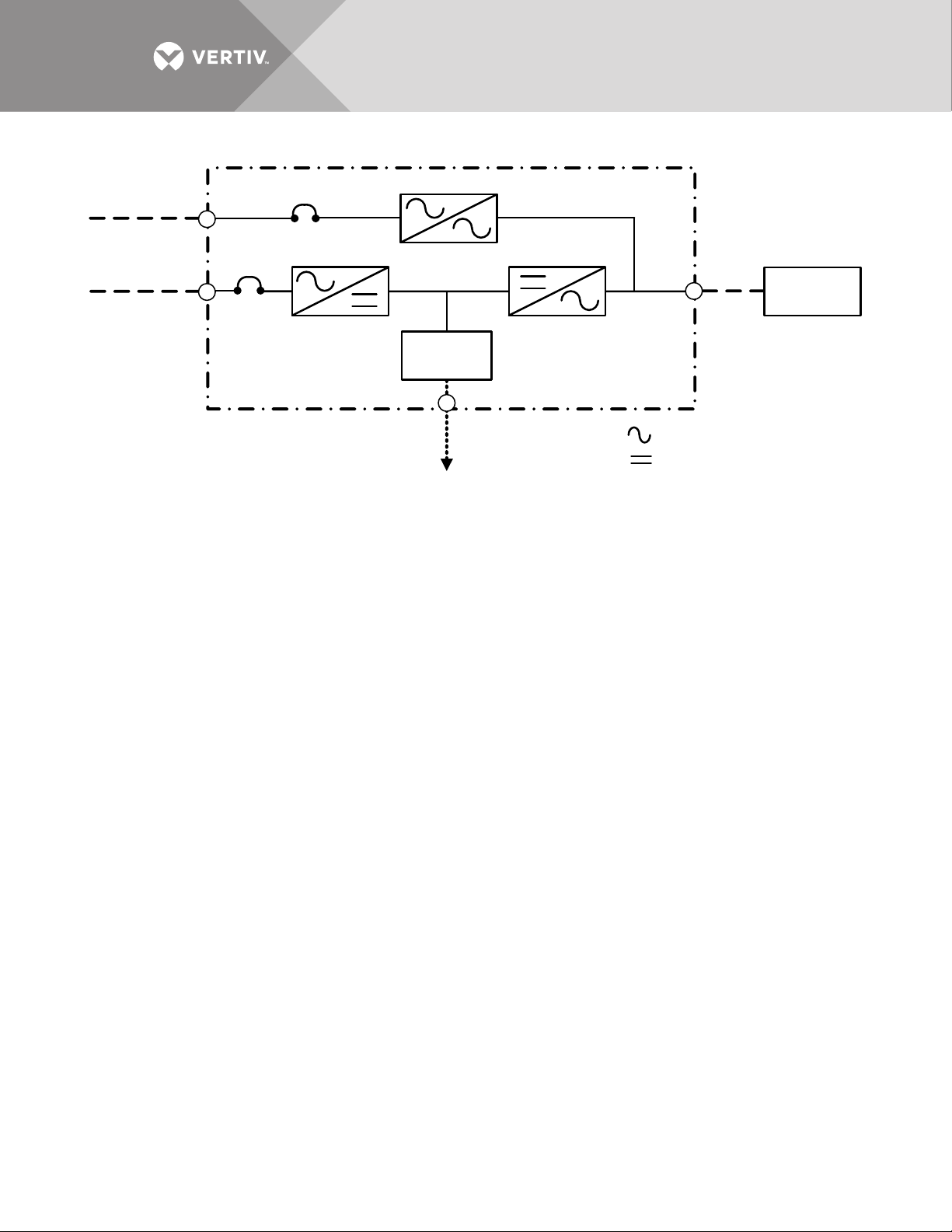
Figure 1 Typical single module UPS system one-line diagram
BFB
CB1
(Note 5)
UPS Module
2 Wire +GND
(See Note 2)
3 Wire
+ GND
To DC Supply
Module Rectifier
AC Input
Module Bypass
AC Input
UPS
Output
3 Wire + GND
Critical
Load
Booster/
Charger
3 Wire + GND
AC
DC
1. UPS rectifier bypass input and output cables must be run in separate
conduits.
2. All power cables from DC supply should be sized for a total maximum of
2V drop at maximum discharge current.
3. Control wiring and power wiring must be run in separate conduits.
4. Vertiv recommends installing grounding conductors.
Vertiv™ |Liebert® NX™ Operation and Maintenance Manual | 4
Page 11

1.2 MODES OF OPERATION
1.2.1 Normal Mode
Operating in normal mode, the Liebert NX's rectifier derives power from a utility AC source and
supplies regulated DC power to the inverter, which regenerates precise AC power to supply the
connected equipment. The rectifier also uses the utility source power to charge the DC sources.
1.2.2 Eco Mode
When the Liebert NX 225-600 kVA is in Eco Mode, the load will be supported by the bypass
source as long as the power quality of the bypass source remains within specified limits. This
reduces energy consumption and boosts efficiency to greater than 98%. If the power quality of
the bypass source deviates from acceptable levels, the inverter will take the load and the UPS will
operate in normal mode. It will remain in normal mode until the power quality of the bypass source
has remained within limits for a suitable time, at which point the Liebert NX will return to Eco
Mode.
Eco Mode may be inhibited either automatically, such as when the Liebert NX is being fed by a
generator source, or manually, by sending a signal to one of the programmable input contacts.
Examples of control circuits to provide this functionality and a more detailed explanation of Eco
Mode operation can be found in 2.6 - Eco Mode Active.
1.2.3 Bypass Mode
When the Liebert NX is in bypass mode, the load is directly supported by utility power and is
without DC source backup protection.
The Liebert NX’s inverter and bypass static switch will shift the load from the inverter to bypass
mode without an interruption in AC power if the inverter is synchronous with the bypass and any
of the following occurs:
•Inverter fails
• Inverter overload capacity is exceeded
• Inverter is manually turned Off by the user
• UPS is operating on battery and battery voltage reaches end of discharge level
NOTE
If the inverter is not in sync with the bypass, the static switch will transfer the load from the
inverter to the bypass WITH interruption in AC power to the critical load. The default interruption
time is 16ms; the minimum is 4ms. Vertiv
™
can adjust the length of the interruption.
1.2.4 Battery Mode
When utility AC power fails, the Liebert NX protects the critical load by instantaneously
channeling DC source power to the inverter, which continues supporting the critical load without
interruption.
When utility power returns and is within acceptable limits, the Liebert NX automatically shifts
back to Normal mode, with the rectifier powering the critical load.
1.2.5 Maintenance Bypass
The installation of a Maintenance Bypass Cabinet or Assembly is recommended to allow you to
totally isolate the UPS from all power sources. Use of the Maintenance Bypass is described in
2.0 - Operation.
Vertiv™ |Liebert® NX™ Operation and Maintenance Manual | 5
Page 12

1.3 OPTIONS
A number of options are available from Vertiv for your UPS system. Some options are not
available for all ratings. Described below are the most frequently provided options. Other options
are available. Contact your Vertiv sales representative for more information.
• LIFE Services™—A remote service delivery capability which enables the UPS to alert a special Vertiv
Support Center to provide more efficient and proactive identification, resolution, and prevention of
potential UPS issues.
• Network and BMS Connectivity and Monitoring—Communication cards support SNMP, Modbus or both
(Dual Protocol)
• Battery and Racks—The batteries provide power in the event of a power outage. The Liebert NX UPS can
use a variety of battery types, provided the battery plant is designed for the UPS DC voltage range and the
load requirements of your application.
• Battery Cabinets—Valve-regulated, lead-acid (VRLA) sealed batteries are available in matching cabinets
for convenient installation and maintenance in otherwise unprotected space. Depending on the UPS
module rating, two or more cabinets may be connected in parallel to provide the additional run time.
• Module Battery Disconnect—The UPS system utilizes a separate Module Battery Disconnect for remotely
located batteries. A sensing circuit in the UPS module, set at the battery low voltage limit, trips the Module
Battery Disconnect to safeguard the battery from excessive discharge. The Module Battery Disconnect
has an undervoltage release mechanism designed to ensure that during any shutdown or failure mode all
battery potential is removed from the UPS system.
• Battery DC Ground Fault Detection—Monitors battery ground fault current and generates a warning on
the UPS touchscreen LCD and other customer-specific annunciation options.
• Maintenance Bypass—This switchboard provides make-before-break maintenance bypass. It includes:
Maintenance Bypass Breaker (MBB) and Maintenance Isolation Breaker (MIB).
• Load Bus Synchronization—The Load Bus Sync (LBS) option keeps independent UPS systems (and
therefore their critical load buses) in sync, even when the modules are operating on DC source or
asynchronous AC sources. This means that critical loads connected to both load buses can switch
seamlessly between the two.
• MultiBus Synch Module (MBSM)—Permits synchronizing operation of up to 11 UPS modules.
• Input Circuit Breaker—The UPS may be equipped with an internal input circuit breaker (CB1).
• Remote Status Panel—This option provides key status indicators. If ordered with your UPS, the power
supply for this option is factory installed. To add this option to a unit which has already been shipped
contact Liebert Service.
• EPO (Emergency Power Off)—Your UPS may be equipped with an EPO button on its front panel near the
operator touch screen. Contacts for a remote EPO to be installed on site are also provided standard on all
units.
• Temperature-Compensated Charging—When the battery temperature exceeds a preset limit (typically
77°F [25°C]), this optional circuit proportionally reduces float charging voltage to prevent overcharging the
battery.
• Battery Load Testing—When activated, this option forces the battery string to assume the load for a short
period of time.
Vertiv™ |Liebert® NX™ Operation and Maintenance Manual | 6
Page 13
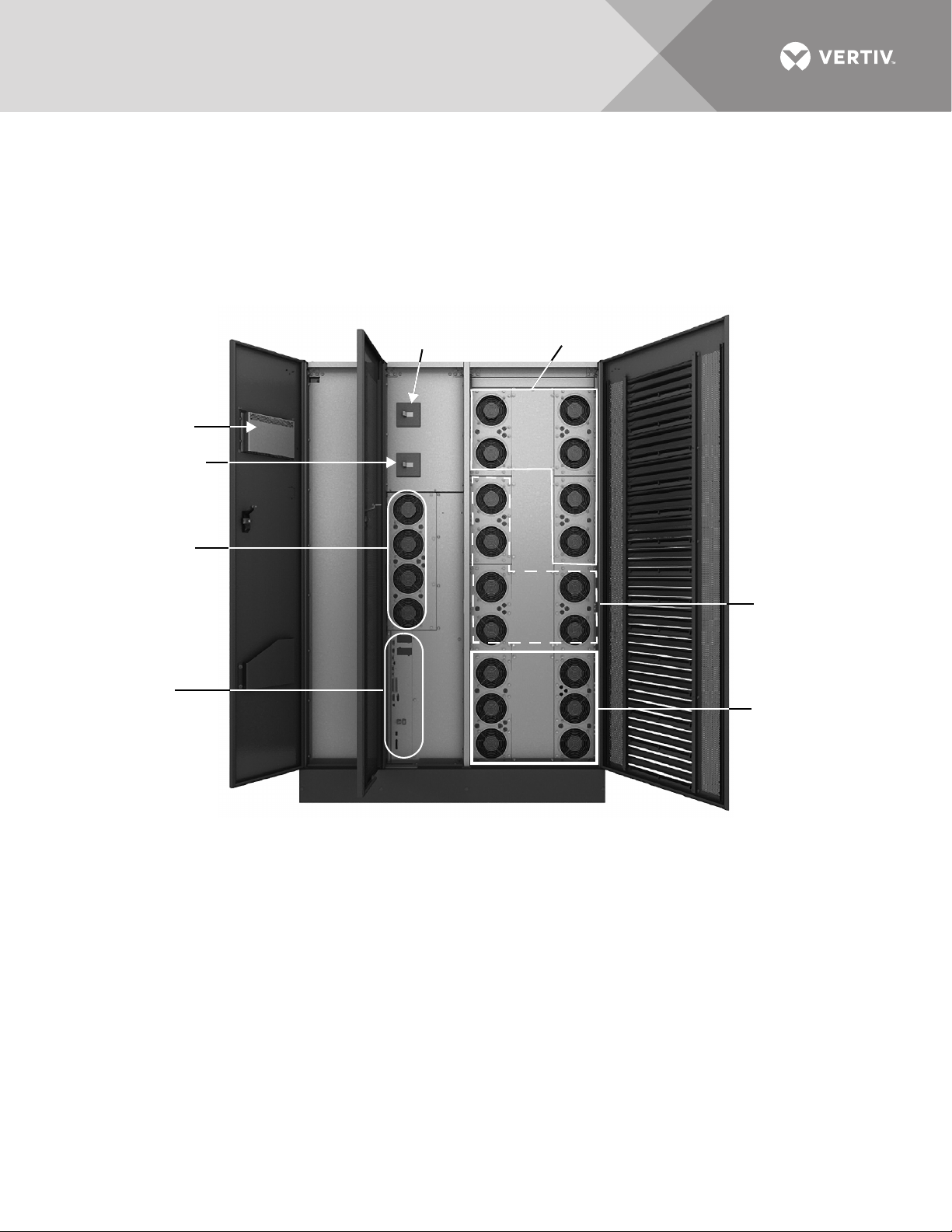
2.0 OPERATION
Input Circuit
Breaker, CB1
Back-Feed Circuit
Breaker, BFB
Static Switch
Subassembly
External
Communication
Panel (Comms
Options)
Rectifier
Subassemblies
Inverter
Subassemblies
DC-DC
Converter
Subassemblies
Control LCD
The Liebert NX UPS is equipped with a microprocessor-based display touchscreen designed for
convenient and reliable operation. The display is driven by menu-prompted software.
2.1 PHYSICAL LAYOUT OF THE UPS
Figure 2 Main component locations—225-300kVA Liebert NX
Vertiv™ |Liebert® NX™ Operation and Maintenance Manual | 7
Page 14
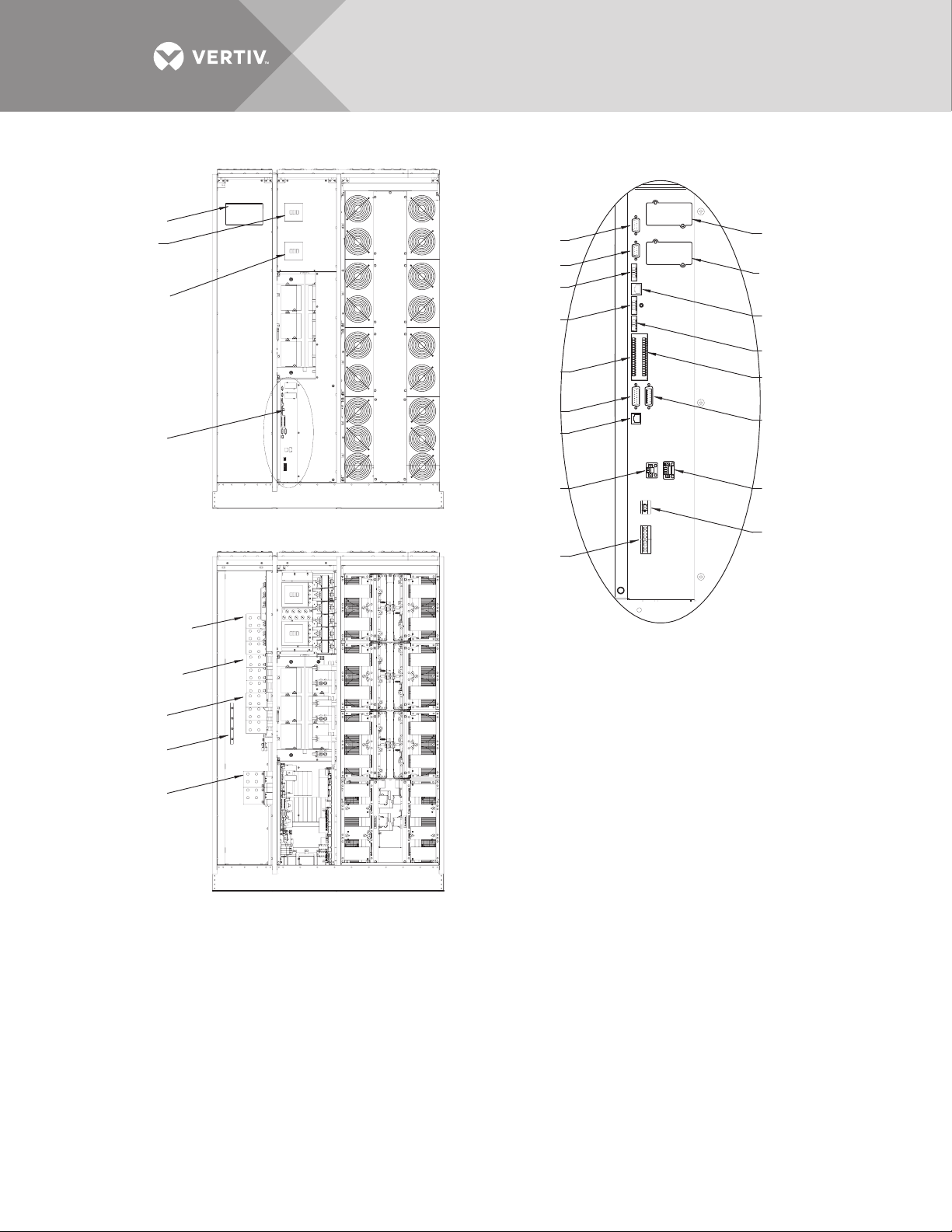
Figure 3 Main component details—225 to 300kVA Liebert NX
Control LCD
Main Input
Circuit Breaker
(CB1), optional
Backfeed Circuit
Breaker (BFB)
External
Communication
Panel, See Detail A
Bypass Busbars
Ø, A, B, C
Rectifier Input
Busbars Ø, A, B, C
Front Doors Removed
X6
XT1/2
XT3/8
TB2
X19A
X20
XT2
(Non-Functional)
TB3
(See specific control wiring drawings)
X3
Detail A
External Communication Panel
XS3
XS6 (LIFE)
X9
XT4
TB1
X19B
XT1
(Non-Functional)
XB4
Output Busbars
Ø, A, B, C
Input Ground
Busbar
Battery
Busbars (+ /-)
U38-3C-2000
Rev. 2
Doors and Inner Skins Removed
Vertiv™ |Liebert® NX™ Operation and Maintenance Manual | 8
Page 15
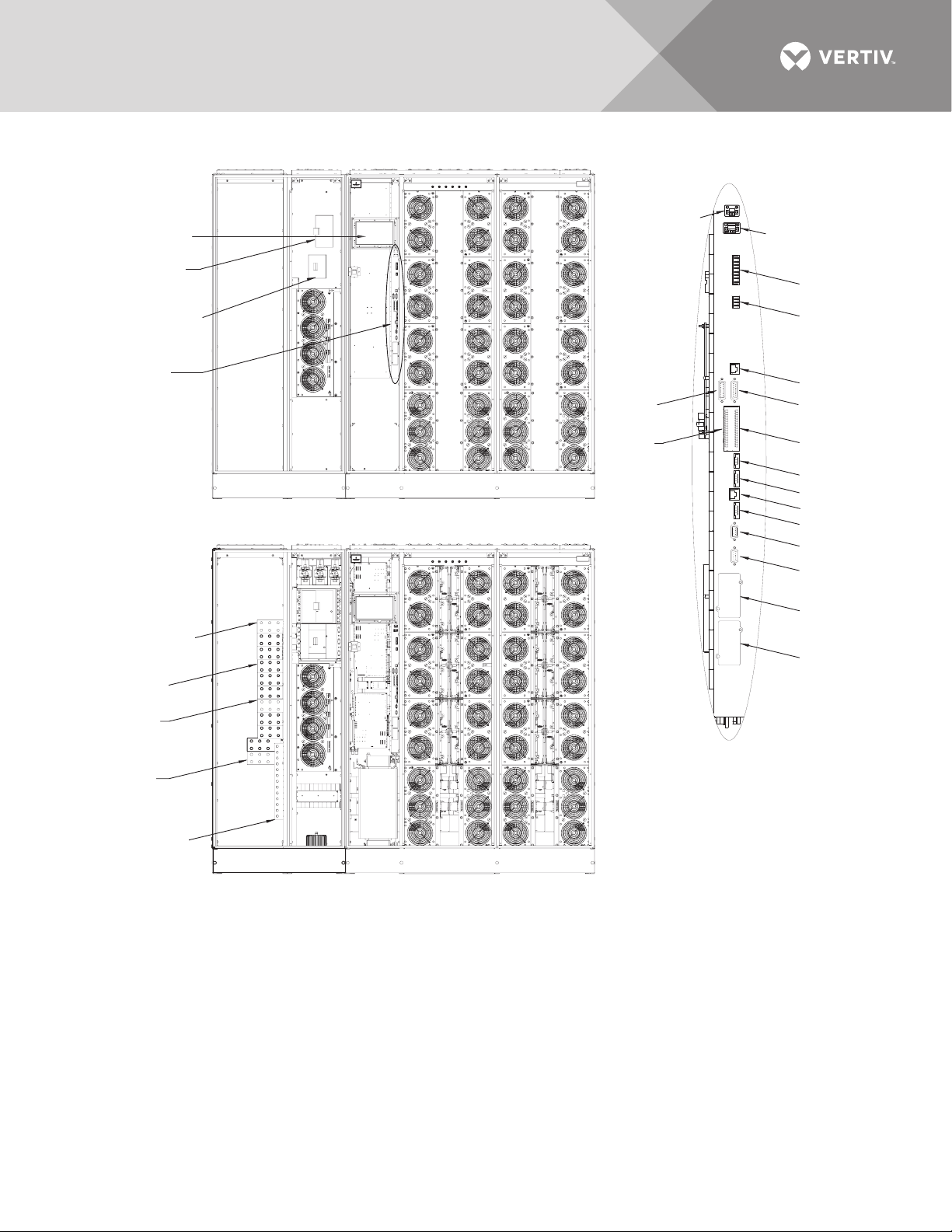
Figure 4 Main component details, 400-600kVA Liebert NX
Control LCD
Main Input
Circuit Breaker
(CB1), optional
Backfeed Circuit
Breaker (BFB)
External
Communication
Panel, See
Detail A
Bypass Busbars
Ø, A, B, C
Rectifier Input
Busbars Ø, A, B, C
Input Ground
Busbar
Output
Busbars
Ø, A, B, C
Battery
Busbars (+ /-)
X3
XS3
X6
XT1/2
XT3/8
X19A
X20
X9
XT4
X19B
XT1
(Non-Functional)
XT2
(Non-Functional)
XS6 (LIFE)
TB2
TB3
TB4
TB1
Doors and Inner Skins Removed
Front Doors Removed
Detail A
External Communication Panel
(See specific control
wiring drawings)
U38-6C-2000
Rev. 2
2.2 INTERFACE DISPLAY FEATURES
The Liebert NX interface display enables the operator to perform such tasks as:
The touchscreen display has a blue background and multicolored text. The display turns On
automatically, but dims and the back-light goes out after 15 minutes of inactivity. Touching the
screen will reactivate the back-light for 15 minutes. If any screen other than the mimic screen is
Vertiv™ |Liebert® NX™ Operation and Maintenance Manual | 9
• Check operational status
• Monitor the power flow through the UPS system and all meter readings
• Execute operational procedures
• Check status reports and event files
• Adjustment programmable parameters
Page 16

accessed, that screen will be displayed for 5 minutes without any interaction. If there is no activity
4
1
3
5
9
2
6
8
7
1. Bypass Input: Voltage and frequency readings
2. Animated One Line Mimic
3. System Status
4. About Button
5. Output: Voltage, current and frequency readings
6. Battery: Voltage and current readings
7. Control Buttons
8. Menu Buttons
9. Line power Input: Voltage, current and frequency
readings
Green
Gray
Green
Green
Green
COLOR CODE FOR ICONS
AND POWER PATH LINES
Green = OK and In the Active Power Path
Gray = Not Active
Yellow = Advisory
Red = Faulted or Disabled
Green
Critical
Load
BFB
UPS Module
To DC Supply
Module Rectifier
AC Input
Module Bypass
AC Input
UPS
Output
AC
DC
Booster/
Charger
for 5 minutes, the display will revert to the basic mimic screen.
Figure 5 Main display screen, typical
Figure 6 Normal Mode
Vertiv™ |Liebert® NX™ Operation and Maintenance Manual | 10
Page 17
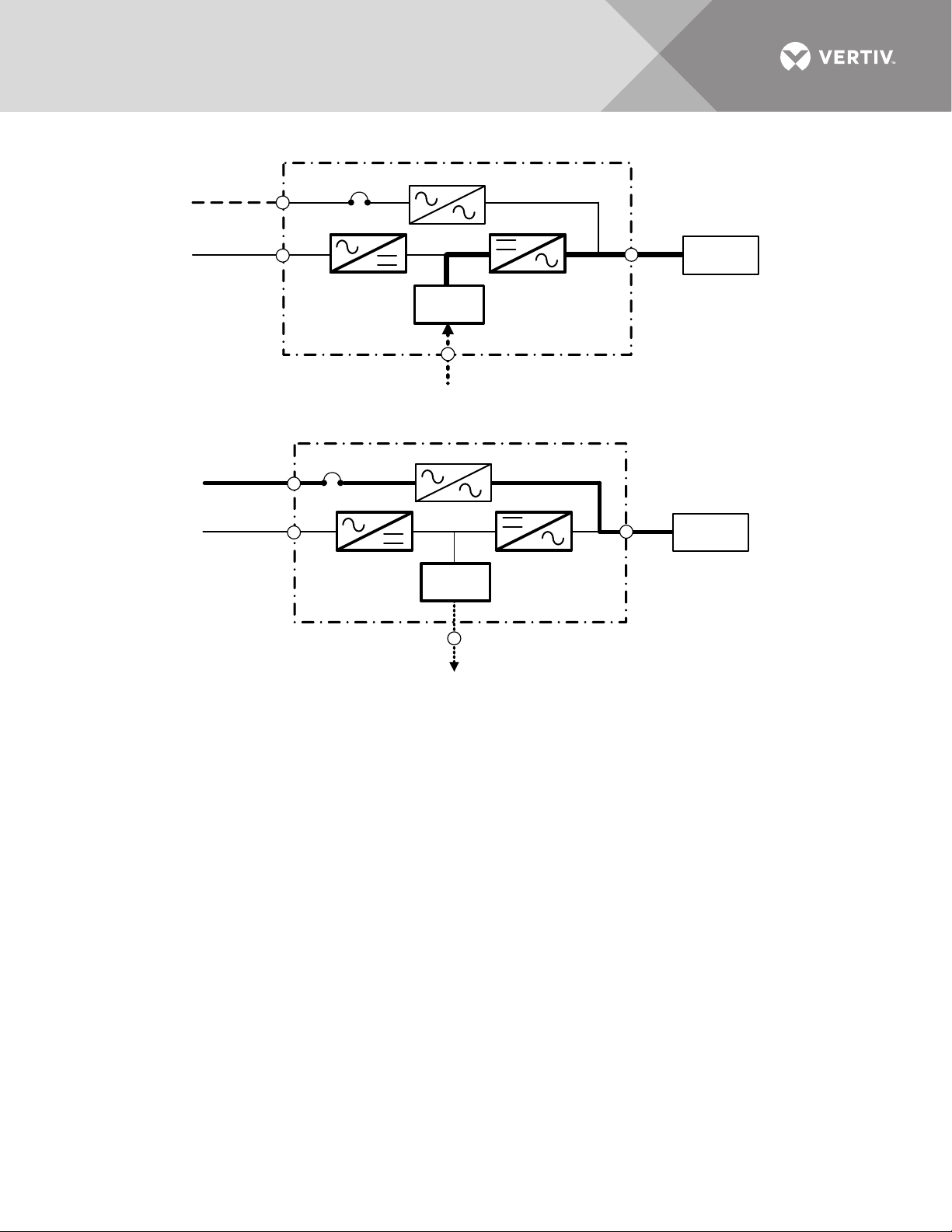
Figure 7 Utility fail
BFB
UPS Module
From DC Supply
Module Rectifier
AC Input
Module Bypass
AC Input
UPS
Output
Critical
Load
Booster/
Charger
BFB
UPS Module
To DC Supply
Module Rectifier
AC Input
Module By pass
AC Input
UPS
Output
Critical
Load
Booster/
Charger
Figure 8 Load on bypass
2.3 TOUCHSCREEN NAVIGATION
Several menu items can be accessed from the main display screen (see Figure 17). These menu
items are detailed in subsequent sections.
2.3.1 Main Display Screen
This is the default screen. It displays the following information:
• Bypass Input Voltage
• Bypass Input Frequency
•Input Voltage
•Input Current
• Input Frequency
•Output Voltage
•Output Current
• Output Frequency
• DC Source Voltage
• DC Source Current
System Status
Only one of the following three status indicators is actively highlighted at any given time:
System Normal Indicator—When the green check mark status icon (?) is highlighted, the system
is operating normally and no warning or alarm has occurred. During line power failures (with all
other conditions being nominal), this icon is not highlighted.
Vertiv™ |Liebert® NX™ Operation and Maintenance Manual | 11
Page 18
Warning Indicator—The yellow triangle icon is activated and highlighted by abnormal
In this case, the UPS is operating in double-conversion mode without power backup. All power paths (except the internal
bypass and maintenance bypasses lines) are green (active). The bypass static switch and the bypass lines are gray,
Green
Gray
Green
Green
Green
Red
conditions that could affect the normal operation of the UPS. These conditions do not originate
with the UPS, but may be caused either by the surrounding environment or by the electrical
installation (line power side and load side). A description of the active warning(s) can be viewed
by touching the yellow triangle or using the Status button at the bottom of the page.
Fault Indicator—When the red circle with white cross is highlighted, immediate attention should
be given to the severity of the alarm, and service should be called promptly. A description of the
active alarm(s) can be viewed by touching the Status button at the bottom of the page.
No matter which indicator is active, all available diagnostic information on the unit can be
displayed by touching this area.
Control Buttons: Start Inverter and Stop Inverter—The touchscreen display features two
buttons for starting and shutting down the inverter. The start/stop control incorporates a safety
feature for preventing accidental operation. When the start or stop function for the inverter is
selected, a pop-up window appears asking for confirmation of the action.
Reset Fault—Reset faults (becomes red when there is a system fault).
Alarm Silence—Silence the buzzer in the case of an alarm.
NOTE
If screen is inactive for 30 seconds, the LCD will revert to the system status screen.
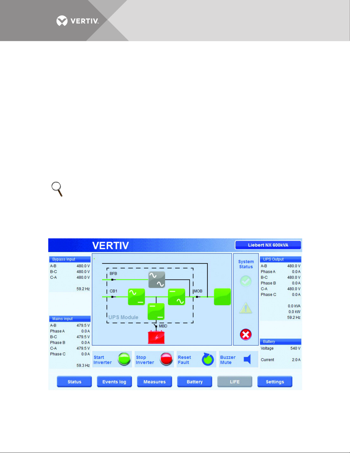
2.3.2 Status
This menu item displays a Status summary of warnings, faults and other events, as well as status
screens for each functional block, such as Rectifier, Inverter and Load.
Figure 9 Main display screen, MBD open
Vertiv™ |Liebert® NX™ Operation and Maintenance Manual | 12
Page 19
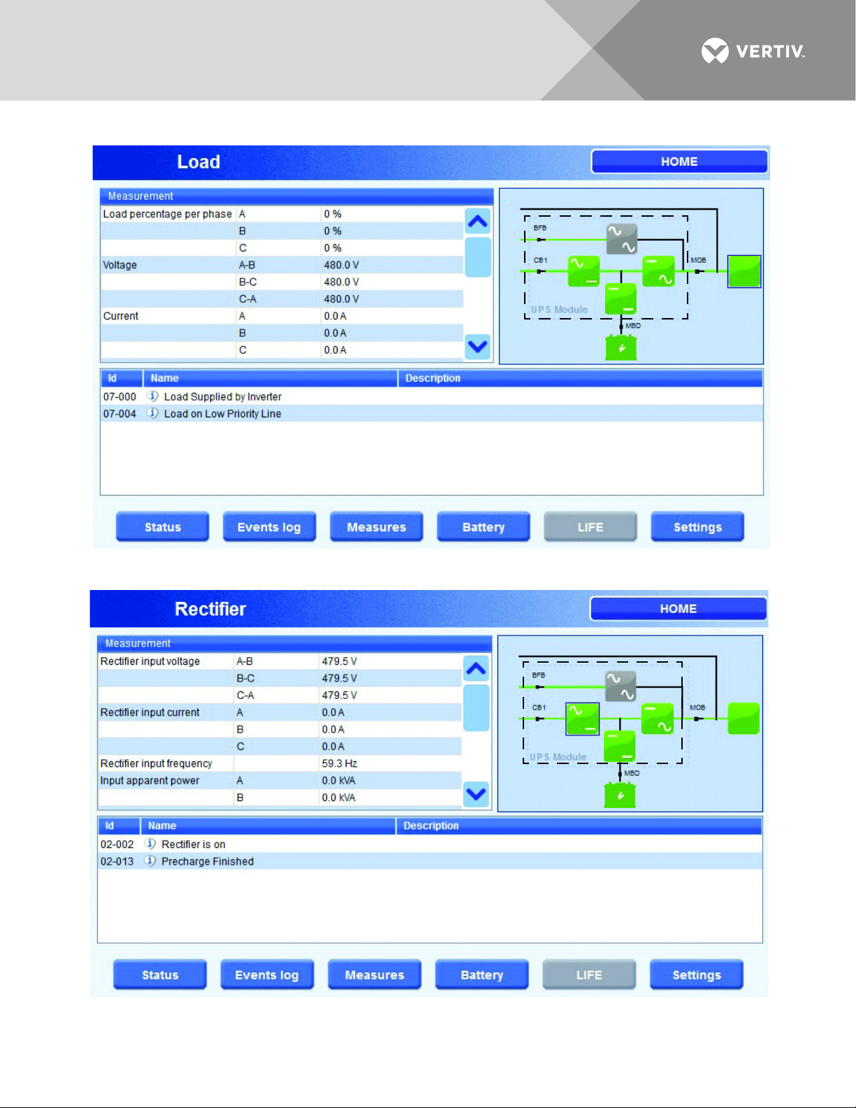
Figure 10 Load status
Green
Green
Green
Green
Gray
Green
Green
Gray
Green
Green
Green
Green
Figure 11 Rectifier status
Vertiv™ |Liebert® NX™ Operation and Maintenance Manual | 13
Page 20
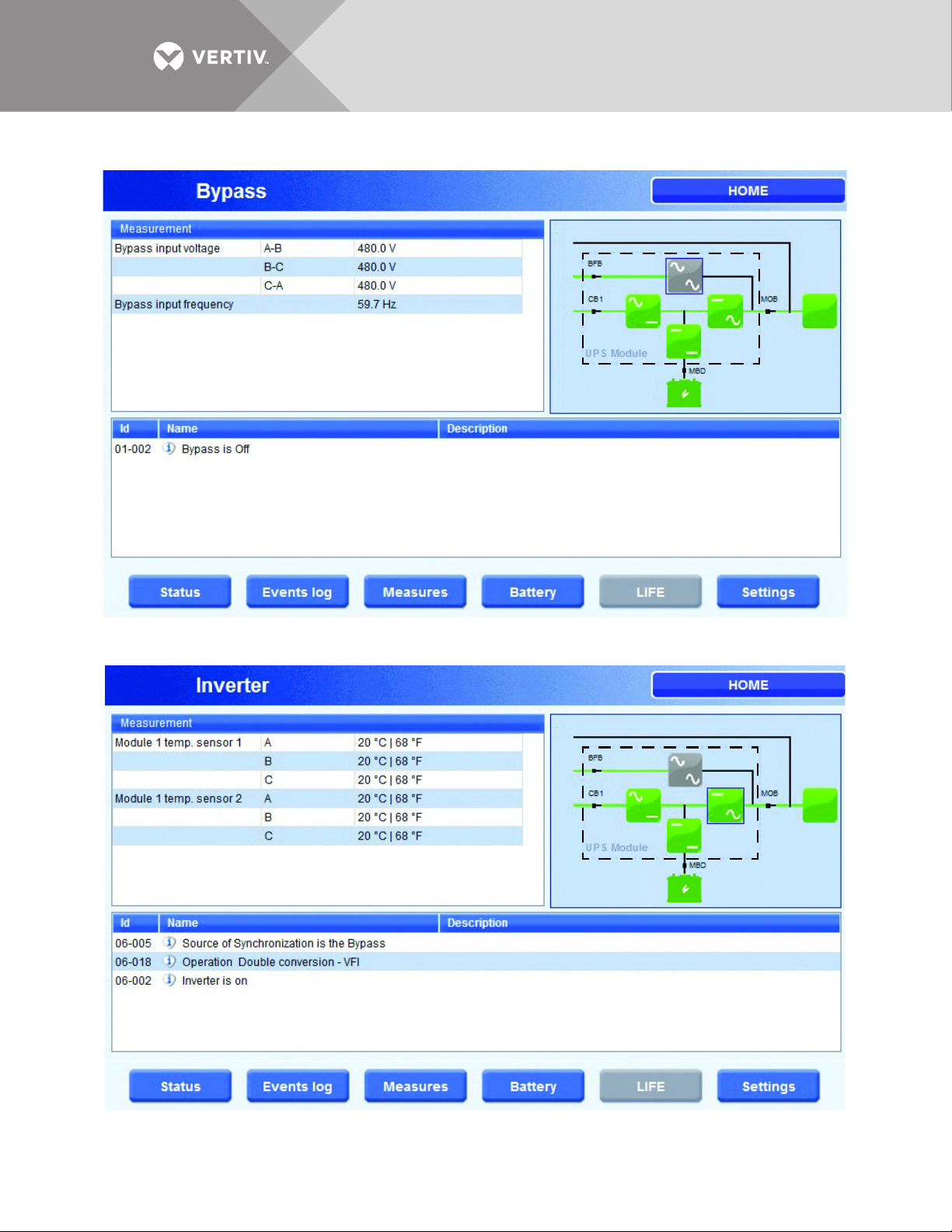
Figure 12 Bypass status
Green
Gray
Green
Green
Green
Green
Green
Gray
Green Green
Green
Green
Figure 13 Inverter status
Vertiv™ |Liebert® NX™ Operation and Maintenance Manual | 14
Page 21
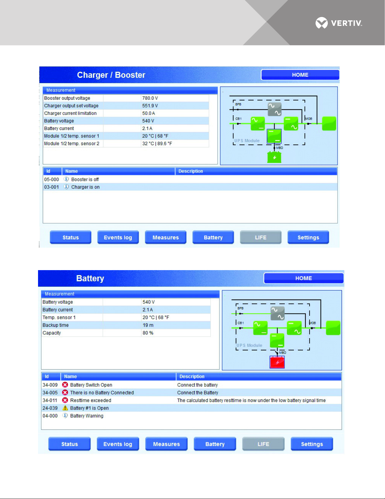
Figure 14 Charger/Booster status
Green
Gray
Green Green
Green
Green
Green
Gray
Green Green
Green
Red
Figure 15 Battery status
Vertiv™ |Liebert® NX™ Operation and Maintenance Manual | 15
Page 22
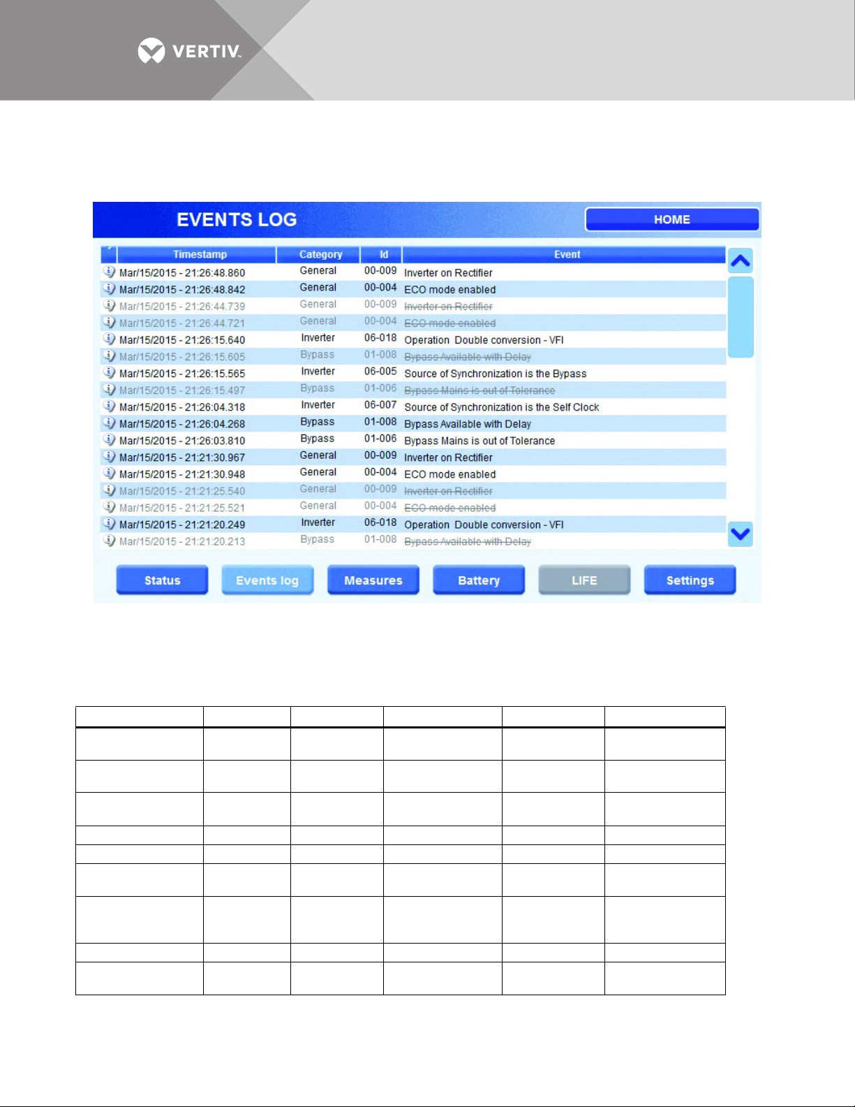
2.3.3 Events Log Menu
This menu item displays recent Events that occurred while the UPS was in operation.
Figure 16 Status summary
2.3.4 Measures Menu
This menu item displays the full set of measurements for each functional block (rectifier, bypass,
booster/charger, batteries, inverter and load).
Table 1 Measurements for functional blocks
Rectifier Bypass Inverter Charger/Booster Battery Load
Voltage - L-L Voltage - L-L Temperatures
Current - Phase Frequency —
Frequency — —
kVA per Phase — — Battery Voltage Backup Time kW per Phase
Temperatures — — Battery Current Capacity kVA per Phase
Rectifier
Output Voltage
Input Supervision
Counter
(# of Mains failures)
———— —Load%
———— —
— — Temperatures — Frequency
—— — —
Booster
Output Voltage
Booster Output
Voltage Setting
Charger Current
Limit
Battery Voltage % per phase
Battery Current Voltage L-L
Temperatures Current per Phase
Overload Time
Remaining
Tota l Loa d Power
(kW)
Vertiv™ |Liebert® NX™ Operation and Maintenance Manual | 16
Page 23
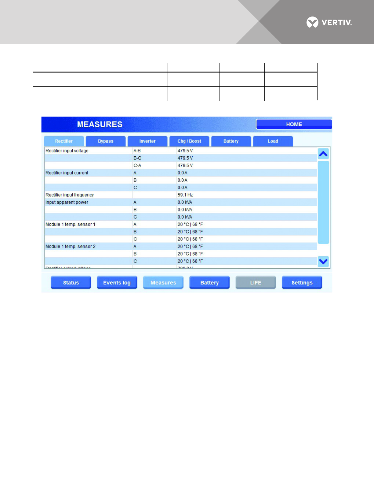
Table 1 Measurements for functional blocks
Rectifier Bypass Inverter Charger/Booster Battery Load
———— —
———— —
Figure 17 Rectifier measures
Tota l Loa d Power
(kVA)
Ambient
Temperature
Vertiv™ |Liebert® NX™ Operation and Maintenance Manual | 17
Page 24
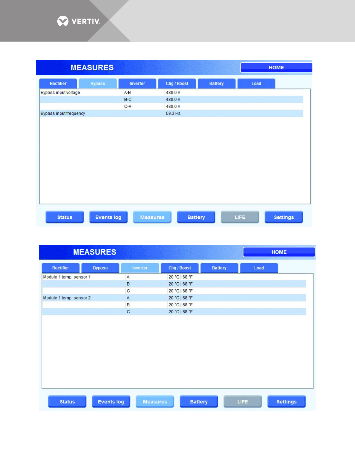
Figure 18 Bypass measures
Figure 19 Inverter measures
Vertiv™ |Liebert® NX™ Operation and Maintenance Manual | 18
Page 25
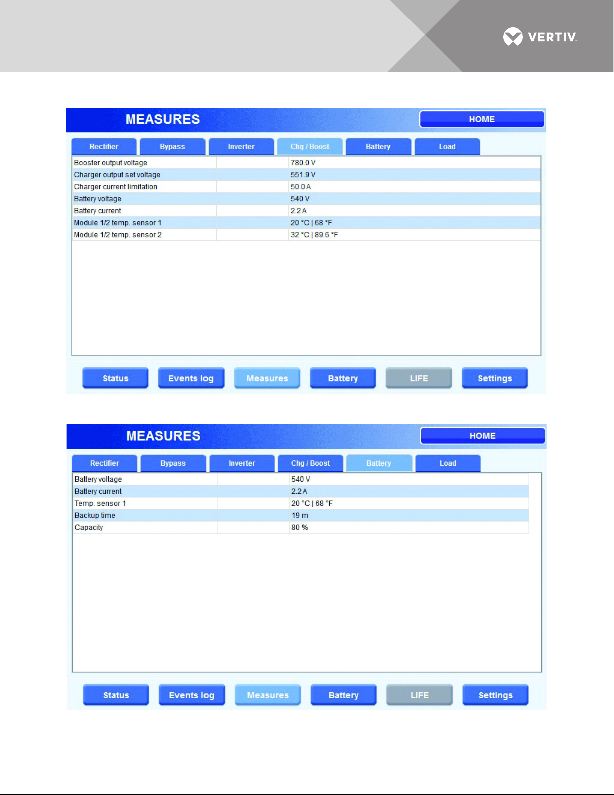
Figure 20 Charger/Booster measures
Figure 21 Battery measures
Vertiv™ |Liebert® NX™ Operation and Maintenance Manual | 19
Page 26

Figure 22 Load measures
Vertiv™ |Liebert® NX™ Operation and Maintenance Manual | 20
Page 27

2.3.5 Battery Menu
!
This menu displays battery status/parameters, such as temperature, cell voltage, capacity and
run time, as well as commands that enable the user to configure and execute a battery test.
Battery Status
• Battery Status— Verify whether battery is charging
• Charger Status—Verify Battery Charger status
• Battery Test Status—Verify details of the last battery test executed
• Automatic Battery Test Status—Verify details related to automatic battery test
Battery Test
The following commands can be set using this page:
• Enable automatic battery test—Using this command, the Automatic Battery test is enabled using the
existing parameter configuration.
• Configure and manage Manual Battery test. Features are:
• Test duration and Min Voltage can be modified using the + and - buttons
• Start battery test using dedicated command button (Start Battery Test)
• Test duration can be monitored on a dedicated progress bar (Battery test progress bar)
• The battery test can be aborted while it is running with the Stop Battery test button
• Battery test status provides immediate information about test status
Battery Equalize Charging
WARNING
Risk of electric shock, explosive reaction, hazardous chemicals and fire. Can cause
equipment damage, personal injury and death.
Battery equalize charging should be performed only by specially trained personnel or
Vertiv Vertiv personnel. Contact Vertiv before enabling equalize charging with valveregulated, lead-acid batteries, such as those used in Liebert battery cabinets. Refer to the
battery manufacturer’s manual, available on the manufacturer’s Web site, for specific
information about equalize charging
Because individual battery characteristics are not identical and may change over time, the UPS
module is equipped with circuitry to equalize battery cell voltages. This circuit temporarily
increases charging voltage to maintain flooded type battery cells at full capacity.
Vertiv™ |Liebert® NX™ Operation and Maintenance Manual | 21
Page 28

Battery
Equalize
charging
settings
Vertiv™ |Liebert® NX™ Operation and Maintenance Manual | 22
Page 29

Battery Measures
Stop Battery
test button
This section monitors variables applicable to the battery.
Figure 23 Battery parameters
Vertiv™ |Liebert® NX™ Operation and Maintenance Manual | 23
Page 30

2.3.6 LIFE™ Menu
1. LIFE.net status
• LIFE.net option
(Present/Not
present)
Shows whether the “LIFE.net option is available
on the UPS.
• LIFE.net (Enabled/Disabled)
Shows whether the “LIFE.net option has been
started.
• Current UPS
date/time
dd.mm.yy hh:mm:ss
Displays the time used by the UPS to timestamp the Life data
• ‘Set Sampling
Mode button
Set samling/service
mode
Toggles LIFE.net operating modes between
‘service’ and sampling’: service is used when
UPS maintenance is in progress.
4. Call type
• Routine call The UPS is making its regular ca ll.
• Emergency call The UPS is making an Emergency call.
• Manual call
The UPS is making a Manual Call or an automatic extra call to
reset an emergency condition which is no longer active.
• Buffer full call
The UPS is making a call to empty its diagnosti cs history buffer,
which is full and cannot store any more data.
• ‘Manual call
request’ button
When this button is pressed, the UPS is forced manually to
make an immediate call to the LIFE station.
2. UPS calls status
• Next scheduled
call
dd.mm.yy hh:mm:ss Displays the time of next regular UPS call.
• Emergency calls (Enabled/Disabled)
Shows whether UPS emergency calls are
enabled or have been inhibited by the
Life Station for a particul ar reason.
• Delayed call in dd.mm.yy hh:mm:ss
Displays the seconds countdown after
which the UPS will repeat a previously
unsuccessful Life communication.
• ‘Reset delayed
call’ button
Reset delayed call
When this button is pressed, the delayed
call countdown is forced to zero, so that
the UPS repeats the call immediately.
3. UPS connection status
• Not connected The UPS is not connected to the LIFE Station.
• Waiting for connection
The UPS has requested connection to the Life Station and is
waiting for connection to be established.
• Connected The UPS is connected to the LIFE Station.
• LIFE.net data sending in
progress-stage 1
The UPS is transmitting its diagnostics history to the LIFE
station.
• LIFE.net data sending in
progress-stage 2
The UPS is exchanging other service data with the LIFE
station.
• UPS online session in
progress
The UPS has entered the online session requested by the
LIFE Station Administrator, so it can be monitored in real
time.
• Closing connection The UPS is closing the connection.
• Call delayed
The UPS has scheduled a new call bec ause the previous call
This menu displays the information about the Liebert LIFE Services connections, status of calls
and types of calls and allows certain specific commands to be executed. This button will not
active be if the LIFE Services option is not available on the UPS.
Figure 24 LIFE menu
Vertiv™ |Liebert® NX™ Operation and Maintenance Manual | 24
Page 31

2.3.7 Settings Menu
LCD Settings Language Settings
Date and Time Settings
Time Zone Settings
Eco Mode Settings Passcode Settings
This menu item permits changing the LCD settings, selecting the language on the display, setting
the date and time format, choosing the time zone, enabling and disabling Eco Mode and
changing passcodes.
Figure 25 Settings Menus
Vertiv™ |Liebert® NX™ Operation and Maintenance Manual | 25
Page 32

2.4 ANIMATED ONE-LINE MIMIC
This displays all the functional blocks in the UPS. Touching an icon displays detailed information
about the functional block. The blocks color signifies its status:
• Green: Normal
• Yellow: Warning
•Red: Fault
• Gray: Not active but no active fault
Pressing a block, such as Rectifier or Inverter, displays a page with details about the block.
2.4.1 Functional Blocks
This section provides details about the status of each functional block of the UPS. Touching a
block displays a page with status messages and measurements as shown in Tab le 2 .
Table 2 Functional block information
Functional
Block
Rectifier
Bypass Input Voltage L-L, Input Frequency, Temperature Sensor(s)
Inverter Temperature Sensor(s) phases A-B-C
Booster/ChargerBooster Output Voltage, Charger Output Set Voltage, Charger Current Limitation, Battery Voltage,
Battery Voltage, Current, Temperature Sensor(s), Backup Time, Capacity (%)
Load
Measurements Displayed
Input Voltage L-L, Input Current phases A-B-C, Input Frequency, Input Apparent Power phases A-B-C,
Temperature Sensor(s), Output Voltage, Input Supervision Counter
Battery Current, Temperature Sensor(s)
% Load phases A-B-C, Voltage L-L, Current phases A-B-C, Real Power per Phase (kW), Apparent Power
per Phase (kVA), Frequency, Overload Time Remaining, Load %, Total Load Real & Apparent, Ambient
Temperature
2.4.2 About Menu
This button displays the type and size of the unit. Touching this area reveals the serial number,
firmware details and the IP and MAC addresses.
Vertiv™ |Liebert® NX™ Operation and Maintenance Manual | 26
Page 33

Figure 26 About menu
2.5 MODES OF OPERATION
This section illustrates the flow of power through circuit breakers, switches and UPS components
during various modes of operation. The same modes of operation apply to all configurations of
the Liebert NX. Highlighted (thick) lines in the diagrams indicate power flow and power
availability. These illustrations do not show an alternate power source (generator) and automatic
transfer switch (external to the UPS) that might be present. These illustrations do not show
optional CB1 installed. If CB1 is installed, it is assumed to be closed.
2.5.1 Load on Bypass
In this operating mode, the connected loads are supplied from line power via the Static Bypass
Switch. The Static Bypass Switch is used to provide power to the loads if the load has been
transferred from inverter or if the power conversion systems in the UPS are in a fault condition. If a
severe overload or fault occurs on the UPS output, the bypass will provide additional current for
800 milliseconds to help clear the fault. If the fault is not cleared, the UPS will transfer to bypass.
The bypass operating condition is displayed. From this operating mode, the UPS automatically
reverts to on-line operation after the fault is corrected. Bypass operation can also be specifically
selected from the control panel using the push button.
Load on Bypass is shown in Figure 27. The UPS system could be in this mode of operation during
either initial startup or UPS system shutdown or isolation for maintenance.
NOTICE
Risk of unexpected power loss. Can cause equipment damage.
When the critical load is being supplied power from the bypass line and Eco Mode is not active, the load is
vulnerable to utility failure and fluctuations.
Vertiv™ |Liebert® NX™ Operation and Maintenance Manual | 27
Page 34

Figure 27 Load on bypass, UPS not operating
YellowGrayGray
Green
Green
Green
YellowGrayGreen
Green
Green
Green
Figure 28 Load on bypass, UPS available
Note that Figure 28 illustrates the UPS in Eco Mode. The one-line mimic display appears as
shown in Figure 29.
Vertiv™ |Liebert® NX™ Operation and Maintenance Manual | 28
Page 35

Figure 29 Eco Mode one-line mimic display
Green
Gray
Green
Green Yellow
Green
GreenGreenGreen
Gray
Green
Green
For more information on Eco Mode, see 2.6 - Eco Mode Active.
2.5.2 Normal Mode—Load on UPS
Figure 30 Load on UPS, bypass available
2.5.3 Input Power Failure—Load on DC Source
If the utility AC power source fails or is outside the acceptable range, the DC source becomes the
power source for the UPS inverters. The UPS continues to supply power to the critical load and
also to the UPS controls.
Vertiv™ |Liebert® NX™ Operation and Maintenance Manual | 29
Page 36

Use the Battery Time screen at the UPS to monitor the DC source voltage compared to the
GreenGreenGray
Gray
Green
Green
shutdown value. The time the DC source can sustain the load depends on the load’s power
requirements and the batteries’ capacity.
The battery block in the UPS module monitor/mimic display indicates Charge or Discharge and
the current in amperes.
Figure 31 Input power failure, load on DC source
Vertiv™ |Liebert® NX™ Operation and Maintenance Manual | 30
Page 37

2.5.4 Off DC Source
GreenGreenGreen
Gray
Gray
Red
The DC source can be disconnected from the UPS, if required for maintenance, by opening all
battery breakers or if single string is used, the module battery disconnect (MBD) circuit breaker.
In this situation, the UPS module will continue to supply conditioned power to the critical load, but
if input power fails, the UPS system cannot supply power to the load.
NOTICE
Risk of unexpected power loss to the connected load. Can cause equipment damage.
When the UPS is operating with all battery breakers or the module battery disconnect (MBD) circuit
breaker(s) open, the critical load is not protected from loss of the utility source power.
Figure 32 Load on UPS, DC source not available
2.5.5 Remote Emergency Power Off
The Remote Emergency Power Off (REPO) control is a user-provided switch located remotely
from the UPS system. It usually is installed in the same room as the critical load equipment. This
mode can also be initiated by an automatic contact closure in the same external circuit as the
manually operated switch.
When the REPO switch is operated, the UPS will shut down and open battery circuit breakers. All
power through the UPS is removed from the load. In many systems, the REPO circuit also opens
the circuit breakers that provide power to the bypass lines and the UPS controls. Refer to 2.7.5 -
Shut Down Single Module UPS System.
Vertiv™ |Liebert® NX™ Operation and Maintenance Manual | 31
Page 38

Figure 33 Remote Emergency Power Off
GrayRedRed
Red
Red
Red
To restart a UPS module after an EPO event:
1. Verify that the original condition that required the EPO action has been corrected.
2. Verify that the system is isolated and that it is safe to restart (e.g., no personnel would be at risk if the system
is energized, etc.).
3. Follow the normal startup procedures for the system based on its configuration (single module or 1+N
distributed bypass multi-module system).
2.6 ECO MODE ACTIVE
The UPS has determined that the bypass power quality is adequate for Eco Mode
operation. The touchscreen LCD will display a message that the UPS is operating on
Eco Mode. Eco Mode will be symbolized on the touchscreen LCD with a leaf symbol.
Active Eco Mode is enabled on the Liebert NX 225-600 series. The mode is
incorporated in all single module systems and in multi-module (distributed bypass) units with
Firmware Version 1.04 or newer. It is referred to as an Active Eco Mode because the rectifier
remains On to float charge the battery and the inverter controls remain powered.
Active Eco Mode in the Liebert NX 225-600 provides performance meeting the CBEMA and ITIC
curves for electronic loads, providing sufficient current to ride through the transition to and from
inverter operation. However, some coordination must be considered if the system includes
downstream static transfer switches that base switch decisions on voltage waveforms, because
these may be distorted by an event that would cause a transfer.
2.6.1 Eco Mode Activation and Control
Eco Mode may be activated through the touchscreen LCD. It will be the default mode of operation
until it has been deactivated.
To activate Eco Mode, navigate to the Settings menu on the touchscreen LCD and choose
“Enabled.”
Eco Mode may also be inhibited through a signal to one of the programmable input contacts. This
is normally set up to occur automatically if the UPS module becomes supplied by a backup or
emergency input power supply, such as a generator.
Eco Mode Adjustments
In most cases, the default tolerance settings for Eco Mode should be appropriate for correct and
reliable operation. However, the limits for voltage and frequency can be adjusted by Vertiv.
Contact Liebert for more information.
Vertiv™ |Liebert® NX™ Operation and Maintenance Manual | 32
Page 39

2.6.2 Active Eco Mode
If priority has been set to Active Eco Mode, the control system will allow the Liebert NX to
continuously monitor the condition of the input supply, including its failure rate, to ensure
maximum reliability for critical users. That analysis determines whether the Liebert NX supplies
the load through the bypass source or the conditioned line. This operational mode, which allows
significant energy savings by increasing the overall AC/AC efficiency of the UPS up to 98%, is
primarily intended for general purpose ICT applications. However, it does not provide the same
output power quality as when the UPS operates in double conversion mode. It will therefore be
necessary to verify whether this mode is appropriate for special applications.
2.6.3 Normal—Active Eco Mode
The operating mode will depend on the quality of the source supply in the recent past. If the line
quality has remained within permitted tolerance parameters, the bypass source will provide
continuous supply to the critical AC load through the bypass static switch. The IGBT inverter
control system will remain in constant operation and synchronization with the bypass source
without driving the IGBT’s. This ensures that the load can be transferred to the conditioned line
within the limits of the CBEMA and ITIC curves and IEC 62040-3: 2010 Curve 1 when there is a
deviation from the selected input power tolerance levels. If the direct line failure rate has been
outside permitted parameters, the Liebert NX will supply the load from the conditioned line. The
battery charger supplies the energy necessary for maintaining float charge to the battery.
2.6.4 Inverter Stop—Active Eco Mode
If the inverter is stopped for any reason, there will be no transfer to the conditioned line and the
load will continue to be supplied by the bypass source. The source voltage and frequency values
must be within the tolerance limits specified.
2.6.5 Overload—Active Eco Mode
If an overload lasting longer than the maximum capacity specified for the bypass static switch,
the load is maintained on the bypass source and a message will appear on the LCD to warn about
the potential risk related to this condition. This default behavior can be changed (via a serviceaccessible firmware setting) to force a load transfer to the conditioned line (similar to that
described below), even if the bypass source is available. In the event of an overload in conjunction
with an unsuitable bypass source supply, the Liebert NX will transfer the load from the bypass
source to the conditioned line (assuming that the UPS was operating from the bypass source)
and the inverter will continue to supply the critical load for a period that depends on the degree of
the overload and the UPS rating. Visual and audio alarms alert the user to the problem.
2.6.6 Emergency—Due to Source Supply Failure or Variance Beyond Tolerance Limits,
Active Eco Mode
If the Liebert NX is supplying the load via the bypass source and the bypass source supply varies
beyond tolerance levels (adjustable using the software), the load will be transferred from the
bypass source to the conditioned line. The load is powered from the source via the rectifier and
inverter, (provided the input source remains within the specified tolerances). Should the input
source fall below the lower limit, the batteries will be used to power the load via the inverter. The
user is alerted to the battery discharge by visual and audio alarms and the remaining autonomy is
displayed on the LCD. During this process, it is possible to extend the remaining autonomy by
switching off nonessential loads.
Vertiv™ |Liebert® NX™ Operation and Maintenance Manual | 33
Page 40

2.6.7 Return to Normal Conditions-Active Eco Mode
BFB
CB1
MIB
MBB
When the source supply returns to within tolerance limits, the Liebert NX will continue to supply
the load via the conditioned line for a period that depends on the bypass source failure rate (the
conditioned line draws power from the source, not the battery). When the bypass source has
stabilized, the Liebert NX resumes powering the load from the bypass source. At this time the
battery charger automatically begins to recharge the battery so that maximum autonomy is
available in the shortest possible time.
2.7 MANUAL OPERATIONS—ALL SYSTEMS
The Liebert NX UPS is designed to function unattended by an operator. The system control logic
automatically handles many important functions, as explained in 2.8 - Automatic Operations.
Other procedures must be performed manually.
Manual procedures available to the operator include startup, load transfers and shutdowns.
These are performed with the touchscreen and some manually operated circuit breakers and
switches.
This section lists typical step-by-step instructions.
• Startup—Including initial startup, recovering from input power failure, recovering from DC source
shutdown and recovering from shutdowns for emergencies or maintenance.
• Load Transfers—Including transfers from UPS to bypass and retransfers from bypass to the UPS system.
• Maintenance Bypass Load Transfers—Including transfers from internal bypass to maintenance bypass and
transfers from maintenance bypass to internal bypass.
• Shutdowns-Including module shutdowns for maintenance and emergency shutdowns.
Figures 34 through 39 illustrate the possible maintenance bypass configurations for Liebert NX
systems.
Figure 34 Maintenance bypass configurations—Two breaker
Vertiv™ |Liebert® NX™ Operation and Maintenance Manual | 34
Page 41

Figure 35 Maintenance bypass configurations—Three breaker for single-input UPS
MIB
MBB
CB1
BIB
BFB
MIB
MBB
CB1
BIB
BFB
CB1
MIB
MBB
RFB
BFB
BIB
Figure 36 Maintenance bypass configurations—Three breaker for dual-input UPS
Figure 37 Maintenance bypass configurations—Four breaker for dual-input UPS
Vertiv™ |Liebert® NX™ Operation and Maintenance Manual | 35
Page 42

Figure 38 Maintenance bypass configurations—Four breaker for dual-input UPS, No CB1
MIB
MBB
RIB
BFB
BIB
MIB
BFB
CB1
MOB
MOB
MBB
BFB
CB1
Figure 39 Maintenance bypass configurations—Distributed bypass, 1+N multi-module
2.7.1 Startup—Single Module System
This section lists step-by-step instructions for UPSs with maintenance bypass configurations as
shown in this manual. If the system has a different maintenance bypass operation, consult the
provider of that system for operating procedures. The procedure assumes that the UPS
installation inspection and initial startup were previously performed by Vertiv™. An Vertiv-
Vertiv™ |Liebert® NX™ Operation and Maintenance Manual | 36
Page 43

authorized representative must perform the initial system startup to ensure proper system
!
!
operation.
WARNING
Risk of electric shock. Can cause equipment damage, personal injury and death.
The following procedure provides power to the critical load distribution system. Verify that
the critical load distribution is ready to accept power. Make sure that personnel and
equipment are ready for the critical load distribution system to be energized.
Starting the Unit without Power Supplied to the Connected Load
If the installation includes a Maintenance Bypass, power may already be supplied to the critical
load equipment through the Maintenance Bypass. If there is no power to the critical load, apply
power through the UPS bypass line per the following procedure. If the load is being supplied by
Maintenance Bypass, see Startup Single Module System from Maintenance Bypass on
page 38.
During startup, power is supplied to the load through the UPS (internal) bypass line while the UPS
system is being energized. Depending on the reason for the UPS shutdown, power may be
present in the bypass line. To determine this, check the monitor/mimic display screen after
control power is available.
NOTE
If the system was shut down because of an Emergency Off, there may be alarm messages on the
touchscreen that describe system conditions before (or at the time of) the shutdown. Some or all
of the alarm conditions may have been resolved. To clear these alarm messages, turn Off control
power (see Figures 3 and 4).
If the system is a multi-module system, verify that the UPS is in Maintenance bypass mode, then
open the Module Output Breakers (in the distribution switchboard) because the output bus
provides an additional source of control power.
Wait at least 10 minutes for the control power circuitry to completely de-energize. After 10
minutes, turn control power back On.
WARNING
Risk of electric shock and high short circuit current. Can cause equipment damage, injury
and death.
If the UPS has been shut down for maintenance, verify that all of the UPS system doors are
closed and latched. All test equipment must be removed from the system. All electrical
connections must be secure.
1. Before applying power to the UPS module, determine the position of the following circuit breakers and
switches:
• Optional Input Circuit Breaker (CB1)—Verify that this breaker on the front of the UPS cabinet (see
Figures 3 and 4) is in the open position. If this breaker is not supplied, check that the remote input breaker
(RIB) (which will be external to the UPS) is open.
• Module Battery Disconnect (MBD)—Verify that this external breaker is open or tripped. If DC source
cabinets are used, verify that breakers on all the cabinets are open.
• Bypass Backfeed Breaker (BFB)—This circuit breaker (see Figures 3 and 4) should be open.
NOTICE
Risk of improper operation. Can cause equipment damage.
Vertiv™ |Liebert® NX™ Operation and Maintenance Manual | 37
Page 44

If the critical load is NOT already powered through the UPS bypass, make sure that the BFB is open until
instructed to close it. Failure to follow this sequence may result in equipment damage.
NOTE
If power to the critical load is already supplied through this breaker, keep this breaker closed.
2. Start the module:
a. Close the Rectifier Input Breaker (RIB if there is no CB1; if the UPS has a CB1, this is referred to as the RFB
[Rectifier Feeder Breaker]). This breaker is external to the UPS; it may be in the Maintenance Bypass
Cabinet.
b. Close CB1 (located in the module) if the optional input breaker is installed.
NOTE
The rectifier will automatically start if there are no active faults.
c. Wait until the touchscreen LCD finishes booting up. This may takes several minutes.
d. Clear any faults before proceeding.
NOTICE
Risk of improper operation. Can cause equipment damage.
If a fault that has been cleared recurs, contact Vertiv
™
. Do not continue.
NOTICE
Risk of improper operation. Can cause equipment damage.
Do not close the back-feed breaker before the touchscreen LCD is fully booted up and faults are cleared.
e. Close Bypass Backfeed Breaker (BFB).
The equipment mimic screen will be displayed.
The Static switch will turn On and the fans will be powered On.
The load will now be powered by the bypass.
f. On the touchscreen LCD, verify that the Rectifier and Booster are Green.
g. Wait until the DC bus is above 540VDC, then close all DC breakers. Check the touchscreen LCD for
messages and respond appropriately.
h. Press the Start Inverter button on the touchscreen. Press Confirm on the pop-up window and the load will
be energized from the UPS inverter.
NOTICE
Risk of improper operation. Can cause equipment damage.
If an abnormal situation occurs during this startup procedure, open the input circuit breaker and
investigate the problem. Call Vertiv if help is required.
2.7.2 Startup Single Module System from Maintenance Bypass
These instructions are for standard maintenance bypass cabinets that have an SKRU, MIB and
MBB. If the maintenance bypass does not have all of these components, the procedures could be
different. In which case, the user should locate/create specific procedures for their system.
This process includes two operations:
• Activating the UPS internal bypass to parallel the Maintenance Bypass
• Transferring the load from the bypass lines to UPS
Vertiv™ |Liebert® NX™ Operation and Maintenance Manual | 38
Page 45

This assumes that:
• The load is being powered by the Maintenance Bypass
• The MIB is open
• The MBB is closed
• The UPS module is Off
• The RIB is open. (This breaker will be the RIB if the UPS has no CB1; it will be the Rectifier Feeder Breaker
[RFB] if the UPS has an internal CB1 input breaker.)
• CB1 (internal rectifier input breaker, if present) is open
• The BFB is open and
• The DC breakers are open.
1. Start the module:
a. Close the Rectifier Input Breaker (RIB) or the Rectifier Feeder Breaker (RFB). This breaker is external to
the UPS; it may be in the Maintenance Bypass Cabinet.
b. Close CB1 (located in the module) if the optional input breaker is installed.
c. Wait until the touchscreen LCD finishes booting up. This may take several minutes.
d. Clear any faults before proceeding.
NOTICE
Risk of improper operation. Can cause equipment damage.
If a fault that has been cleared recurs, stop immediately and contact Vertiv. Do not continue.
NOTICE
Risk of improper operation. Can cause equipment damage.
Do not close the back-feed breaker before the touchscreen LCD is fully booted up and faults are cleared.
e. Close Bypass Backfeed Breaker (BFB).
The equipment mimic screen will be displayed.
The Static switch will turn On, and the fans will be powered On.
f. On the touchscreen LCD, verify that the Rectifier and Booster are Green and that the DC bus voltage is
above 540VDC.
g. Close the MIB. (see Step i below if using a key interlock system)
The load will now be powered by the UPS bypass in parallel with the Maintenance Bypass.
h. Close all DC (battery) breakers.
NOTICE
Risk of improper operation. Can cause equipment damage.
Do not close the battery breakers until the DC bus is above 540VDC.
i. If using a key interlock system:
1. Depress the key-release unit push button.
2. Turn the key and remove it from the key-release unit.
3. Insert the key into the lock for the Maintenance Isolation Breaker (MIB).
4. Retract the bolt.
5. Close the Maintenance Isolation Breaker (MIB).
6. Verify that the DC bus is above 540VDC.
7. Close all DC (battery) breakers.
NOTICE
Risk of improper operation sequence. Can cause equipment damage.
Failure to close the Maintenance Isolation Breaker (MIB) will interrupt power to the load.
j. Open the Maintenance Bypass Breaker (MBB). The load is now on UPS internal bypass.
k. If using a key interlock system,
1. Remove the key from the lock for the Maintenance Bypass Breaker (MBB) to lock it open.
2. Reinsert the key into the solenoid.
l. Press Start Inverter.
The load will be transferred to the UPS.
Vertiv™ |Liebert® NX™ Operation and Maintenance Manual | 39
Page 46

2.7.3 Load Transfer and Retransfer—Single Module System
Changing the load from the UPS inverter to the UPS bypass is called a transfer. Returning the
load from the UPS bypass to the UPS system is called a retransfer. Note that the UPS system
control logic can initiate automatic load transfers and retransfers. Refer to 2.8 - Automatic
Operations.
Transfer from UPS to Bypass Procedure
1. Press the Stop Inverter menu button on the touchscreen.
2. The load will transfer to Bypass mode and the Inverter will turn Off.
Retransfer from Bypass to UPS Procedure
1. Press the Start Inverter menu button on the touchscreen.
2. The Inverter will synchronize with the bypass and transfer the load to Normal mode.
2.7.4 Maintenance Bypass Load Transfers—Single Module System
Follow these instructions to manually transfer the load between the Maintenance Bypass and the
UPS bypass line. Do not transfer the load between the Maintenance Bypass and the UPS module
(inverter) output. Use the monitor/mimic display screen to verify that the UPS bypass line is
available.
These instructions are for standard maintenance bypass cabinets that have an SKRU, MIB and
MBB. If the maintenance bypass does not have all of these components, the procedures could be
different. In which case, the user should locate or create specific procedures for the system.
NOTICE
Risk of improper operation. Can cause loss of power to connected load, resulting in equipment damage.
Failing to follow the proper sequence when operating any circuit breaker may damage the connected
equipment. Operating a Maintenance Bypass circuit breaker out of sequence could cut Off power to the
critical load.
The UPS system must be on internal bypass before the following procedures are performed or the MIB or
the MBB is operated. Otherwise, the UPS may be damaged and the critical load may lose power.
Transfer with Load on UPS Bypass
1. Transfer the UPS system to bypass. The “OK to transfer” lamp on the key-release unit will light.
2. Press the Stop Inverter button on the touchscreen. The load will transfer to Bypass mode and the Inverter will
turn Off.
NOTE
If the maintenance bypass cabinet or switchboard has any other type of custom interlock, follow
the instructions for that interlock system to remove the key.
3. If using a key interlock system:
a. Depress the key-release unit push button, turn the key and remove from key-release unit.
NOTE
The UPS system is now locked in bypass and cannot be retransferred to the inverter until the key
is reinserted.
b. Insert the key into the lock for the Maintenance Bypass Breaker (MBB); retract the bolt.
4. Close the Maintenance Bypass Breaker (MBB).
NOTICE
Risk of improper operation sequence. Can cause loss of power to connected load, resulting in equipment
damage.
Failure to close the Maintenance Bypass Breaker (MBB) will interrupt power to the load.
5. Open the Maintenance Isolation Breaker (MIB). The UPS system is now isolated from the critical load, and the
load is now on Maintenance Bypass.
Vertiv™ |Liebert® NX™ Operation and Maintenance Manual | 40
Page 47

6. If using a key interlock system:
a. Remove the key from the lock for the Maintenance Isolation Breaker (MIB).
b. Put the key back in the solenoid.
c. Open the battery breakers
7. If UPS bypass shutdown is required, open the Bypass Input Breaker (BIB). This breaker is external to the UPS;
it may be in the Maintenance Bypass Cabinet.
8. Open the BFB.
9. Open CB1 (or the Rectifier Input Breaker [RIB] if the UPS is not equipped with CB1).
Transfer with Load on Maintenance Bypass
1. Verify that the module's rectifier is On and in bypass mode. See 2.7.1 - Startup—Single Module System for the
startup sequence.
2. Close the Bypass Input Breaker (BIB) or verify that it is closed. This breaker is external to the UPS; it may be in
the Maintenance Bypass Cabinet.
3. Close the UPS Backfeed Breaker (BFB). Refer to 2.7.1 - Startup—Single Module System.
4. Close the battery breakers.
5. If using a key interlock system:
a. Depress the key-release unit push button.
b. Turn the key and remove it from the key-release unit.
NOTE
The UPS system is now locked in bypass and cannot be retransferred to the inverter until the key
is returned.
c. Insert the key into the lock for the Maintenance Isolation Breaker (MIB);
d. Retract the bolt.
6. Close the Maintenance Isolation Breaker (MIB).
NOTICE
Risk of improper operation sequence. Can cause equipment damage.
Failure to close the Maintenance Isolation Breaker (MIB) will interrupt power to the load.
7. Open the Maintenance Bypass Breaker (MBB). Load is now on UPS Internal Bypass.
8. If using a key interlock system,
a. Remove the key from the lock for the Maintenance Bypass Breaker (MBB) to lock it open.
b. Reinsert the key into the solenoid.
9. The UPS system may now be transferred from bypass to UPS (see 2.7.3 - Load Transfer and Retransfer—
Single Module System).
2.7.5 Shut Down Single Module UPS System
Perform a Module Shutdown to remove power from the UPS module.
Read all warnings in 5.0 - Maintenance before performing any maintenance on your Liebert NX
UPS. These warnings and cautions must be observed during any work on the UPS.
Use the module monitor/mimic display to determine the operating condition of the UPS module.
1. Press the Stop Inverter button on the touchscreen. This will put the load on bypass.
2. Open all DC breakers.
3. Open the BFB.
4. Open the bypass and rectifier breakers to complete the shutdown.
Vertiv™ |Liebert® NX™ Operation and Maintenance Manual | 41
Page 48

2.7.6 Startup—1+N Multi-Module System with Maintenance Bypass Cabinet
!
WARNING
Risk of electric shock. Can cause equipment damage, injury or death.
This procedure will energize the critical bus. Notify all affected personnel before
performing this procedure.
The UPS module(s) and the load should be de-energized at the beginning of this procedure. All
circuit breakers external to the Vertiv-supplied equipment must be operated by customer
personnel.
1. For initial startup, commissioning agents or authorized personnel should verify that all parallel cables are
properly connected to the UPS units.
2. Close CB1 to the UPS module(s). If CB1 is not installed, skip this step.
3. Close the external rectifier and bypass feeder breakers for all modules to be started. This will start the
rectifier(s). Do not proceed until the LCD is operational on all modules.
4. Verify that the rectifier of each module has started. If not, correct the issue before proceeding.
5. Verify that the DC bus is above 540VDC, then close the Module Battery Disconnect(s) (MBD’s).
6. (If the back-feed breakers were closed and the load was supported through the bypass before Step 1, this will
not be necessary; proceed with Step 7)—Close the Back Feed Breaker (BFB) on each UPS module.
7. Verify that the Bypass Static Switch (BPSS) becomes active when the BFB is closed.
8. Close the external Module Output Breaker (MOB) for each UPS module.
9. Verify the UPS status on the mimic screen. The load should be on the UPS bypass.
10. Close the Maintenance Isolation Breaker (MIB). If a maintenance bypass interlocking scheme is available, then
proceed with the operation of the interlock until the MIB is closed and the MBB is opened.
11. Place the collector bus on inverter:
a. Starting with Module 1, select the Start Inverter icon on the user mimic screen.
b. Verify that the screen says Inverter on pending command for the inverter status.
c. Repeat Steps a and b for all modules. Each module will activate its inverter and turn Off the Bypass Static
Switch (BPSS) after Start Inverter is selected on the last UPS module.
Vertiv™ |Liebert® NX™ Operation and Maintenance Manual | 42
Page 49

2.7.7 Transfer the Load from UPS to Bypass: 1+N System
These instructions are for standard maintenance bypass cabinets that have an SKRU, MIB, and
MBB. If the maintenance bypass does not have all of these components, the procedures could be
different. In which case, the user should locate/create specific procedures for their system.
1. Press the Stop Inverter button on each module’s touchscreen. This will transfer the UPS system to bypass.
NOTE
The inverters will stay online until the Stop inverter button is pressed on the last module if all
modules accepted the STOP INVERTER command.
2. If transferring to a wrap-around Maintenance Bypass
a. If using a key interlock system:
1. The OK to transfer lamp on the key-release unit will light.
2. Depress the key-release unit push button.
3. Turn the key and remove it from the key-release unit.
4. Insert the key into the lock for the Maintenance Bypass Breaker (MBB).
5. Retract the bolt.
b. Close the Maintenance Bypass Breaker (MBB).
c. Open the Maintenance Isolation Breaker (MIB). The UPS system is now isolated from the critical load and
the load is now on Maintenance Bypass.
d. Open the Battery Breakers.
e. If using a key interlock system:
1. Remove the key from the lock for the Maintenance Isolation Breaker (MIB).
2. Reinsert the key into the solenoid.
3. Open the MOB to all modules.
4. Open the BFB for all modules.
5. Open the RIB (or RFB), CB1 and BIB for all modules.
2.7.8 Transfer Load from Bypass to UPS: 1+N Distributed Bypass System
These instructions are for typical switchboard configurations that have an SKRU, MIB and MBB,
plus an RIB or RFB and MOB for each UPS module. If the switchboard configuration does not have
all of these components, the procedures could be different. In which case, the user should
locate/create specific procedures for the system.
1. Verify that each module’s rectifier is On and in bypass mode. See 2.7.6 - Startup—1+N Multi-Module System
with Maintenance Bypass Cabinet for the startup sequence.
2. For every module in the system, close the Module Output Breaker (MOB) or verify that it is closed. This
breaker is external to the UPS; it may be in the Maintenance Bypass Cabinet.
3. Close the battery breaker for each module in the system.
4. If transferring from a wrap-around Maintenance Bypass
a. If using a key interlock system,
1. Depress the key-release unit push button.
2. Turn the key and remove it from the key-release unit.
3. Insert the key into the lock for the Maintenance Isolation Breaker (MIB).
4. Retract the bolt.
b. Close the Maintenance Isolation Breaker (MIB).
c. Open the Maintenance Bypass Breaker (MBB). Load is now on UPS Internal Bypass.
d. If using a key interlock system,
1. Remove the key from the lock for the Maintenance Bypass Breaker (MBB) to lock it open.
2. Reinsert the key into the solenoid.
5. Select the Start Inverter icon on the touchscreen LCD of Module 1. Vertiv recommends starting with Module 1
and continuing in order when instructed to do so.
6. Verify that Inverter pending on command message is displayed in the Inverter section of the Status screen.
7. Re peat Steps 5 and 6 for the remaining modules.
Vertiv™ |Liebert® NX™ Operation and Maintenance Manual | 43
Page 50

NOTE
After the Start Inverter icon on the last module has been selected, all inverters will turn On
simultaneously.
2.7.9 Load Transfer-1+N System—Remove One UPS Module from System (Collective)
NOTICE
Risk of loss of power to the critical load. Can cause equipment damage.
If a UPS module is removed from the collector bus, the remaining modules MUST remain on inverter.
Otherwise, if the offline module control power is cycled (turned Off and then On) while the bypass line(s)
of the remaining UPS module(s) are connected to the collector bus, the output bus will be dropped. This
will remove power from the connected load.
1. Verify that enough modules are online to support the load before proceeding.
2. Open the MOB breaker of the module to be removed.
3. Open the module battery disconnects of the module that has been removed from service.
4. Open the Backfeed Breaker (BFB) of the module that has been removed from service.
5. Open the upstream feeder breakers supplying the UPS rectifier and the bypass. (The rectifier will turn Off at
this time).
2.7.10 Load Transfer-1+N System—Add One UPS Module to the System (Collective)
(Re-energize [Turn On] a partially de-energized 1+N system—Adding a module to the collector
bus.) The inverters of the UPSs connected to the collector bus must be active before this
procedure is begun.
NOTICE
Risk of loss of power to the critical load. Can cause equipment damage.
A load drop will occur if the UPS modules supporting the load are in Bypass Mode and control power is
applied to the offline module (assuming that paralleling cables are installed in the offline module when
control power is turned On).
Paralleling cable connections should be verified by the commissioning agent or other authorized
personnel.
1. Verify that all parallel cables are properly connected to the UPS units.
2. Verify that the Bypass Backfeed Breaker (BFB) is open.
NOTICE
Risk of improper operation sequence. Can cause equipment damage.
Failure to have the BFB open until directed to close it may result in equipment damage.
3. Close CB1 to the UPS module. If CB1 is not installed, skip this step.
4. Close the external rectifier and bypass feeder breakers.
NOTE
The rectifier will start at this time. Do not proceed until the user LCD is operational. Clear any
faults before proceeding. Do not continue if the UPS is displaying an Output Voltage Out Of
Tolerance fault. Contact Vertiv
5. Verify that the rectifier has started. If not, correct the issue before proceeding.
6. Close the Back Feed Breaker (BFB). The Bypass Static Switch (BPSS) should not activate.
7. Verify that the DC bus is above 540VDC, then close the Module Battery Disconnect(s) (MBD’s)
8. Use the UPS status on the mimic screen to verify that the rectifier is On and the BPSS is not active. Do not
proceed if the BPSS is active. Correct the issue before proceeding.
9. Close the MOB. The inverter should automatically start after a short period of time. If the inverter does not
start, then select the Start Inverter icon from the user mimic screen to add the inverter to the collector bus.
10. Verify that all inverters are connected to the collector bus and operating properly.
Vertiv™ |Liebert® NX™ Operation and Maintenance Manual | 44
™
.
Page 51

2.7.11 De-Energize 1+N System With Maintenance Bypass Cabinet
This procedure assumes that the inverters are supporting the load.
1. Place the collector bus on bypass:
a. Starting with Module 1, select the Stop Inverter icon on the user mimic screen.
b. Verify that the inverter status is Inverter off pending command.
c. Repeat Steps a and b for all modules. Each module will activate its Bypass Static Switch (BPSS) and turn
Off its inverter after the Stop Inverter is selected on the last UPS module.
2. Verify that the load is on bypass power.
3. Close the Maintenance Bypass Breaker (MBB). If a maintenance bypass interlocking scheme is available,
proceed with the operation of the interlock until the MBB is closed and the Maintenance Isolation Breaker
(MIB) is opened.
4. Open the external Module Output Breaker (MOB) on each UPS module. The inverters will not turn Off until All
modules have accepted the instruction.
NOTICE
Risk of improper operation. Can cause overheating resulting in equipment damage.
Complete Steps 5 through 7 as quickly as possible. The steps above will cause the fans to stop. Leaving
the UPS in this mode for long may cause the rectifiers to overheat and shut down.
5. Open the Module Battery Disconnect (MBD) on each UPS module.
6. Open the Back Feed Breaker (BFB) on each UPS module.
7. Open the upstream feeds to the UPS rectifier and bypass buses. This will shut Off the rectifier.
2.8 AUTOMATIC OPERATIONS
The Liebert NX UPS is designed to function unattended by an operator. The system control logic
monitors the performance of the UPS, the availability of power sources and the current required
by the critical load.
The system control logic:
• Determines what overload conditions can be sustained without a transfer to bypass.
• Initiates an automatic transfer to bypass to sustain an overload or when selected UPS faults occur.
• Can initiate an automatic retransfer to the UPS after an overload has been cleared.
• Initiates an automatic transfer to bypass and emergency module shutdown when specified UPS faults
occur.
The Overload Transfer and Output Undervoltage alarm messages will initiate an automatic
transfer to bypass. Other UPS faults will initiate an automatic transfer to bypass followed
immediately by the shutdown and isolation of the UPS.
If a manual transfer is required and the UPS is not synchronized to the bypass, there may be a delay
ranging from 4 milliseconds to 120 milliseconds (adjustable by Vertiv) before the transfer is complete.
NOTE
A load transfer to the bypass line will be completed whenever an automatic transfer to bypass is
initiated and the bypass line is available. If the OK to Transfer condition is present, the load
transfer will be uninterrupted. If the status message saying Source of synchronization is the self-
clock or Source of synchronization is the bypass is present, the automatic transfer will be
interrupted for 4 to 120 milliseconds (default is 16 milliseconds). The reliability of the UPS
components makes an interrupted load transfer unlikely.
Vertiv™ |Liebert® NX™ Operation and Maintenance Manual | 45
Page 52

2.8.1 Overloads (Without Transfer)
NOTE
A load transfer to the bypass line will be completed whenever an automatic transfer to bypass is
initiated. If the message Source of Synchronization is the Bypass is present, the load transfer will
be uninterrupted.
If a status message saying Source of synchronization is the self-clock or Source of
synchronization is the bypass is present, the automatic transfer will be interrupted for
4 to 120 milliseconds. The reliability of the UPS components makes an interrupted load transfer
unlikely.
The UPS is capable of sustaining full output voltage (±2% of the nominal voltage) for overload
conditions that remain within (under) the current-versus-time curve of overload capacity
(Tab le 3 ).
Note that the time scale is not linear.
For high current demands of short duration (momentary overloads), the critical load is supplied
simultaneously by both the UPS system and the bypass line. Whenever an overload condition
occurs, you should determine the cause of the overload. If an overload condition exceeds the
overload capacity, the UPS system initiates an automatic load transfer to the bypass line.
For overloads above the Input Current Limit, a DC source, such as a battery system or a
generation source, must be available. The Input Current limit has a default setting of 125% rated
output current.
Table 3 Current-versus-time curves of overload capacity
Overload Time, sec. (min.)
Load (%)
101 8249.9 (137.5) 10,999.8 (183.3) 13,749.8 (229.2) 16,499.7 (275) 16,499.7 (275)
105 1650.0 (27.5) 2200.0 (36.7) 2750.0 (45.8) 3299.9 (55) 3299.9 (55)
110 825.0 (13.75) 1100.0 (18.3) 1375.0 (22.9) 1650.0 (27.5) 1650.0 (27.5)
115 550.0 (9.2) 733.3 (12.2) 916.7 (15.3) 1100.0 (18.3) 1100.0 (18.3)
120 412.5 (6.9) 550.0 (9.2) 687.5 (11.5) 825.0 (13.8) 825.0 (13.8)
125 319.4 (5.3) 425.9 (7) 532.4 (8.9) 638.9 (10.6) 638.9 (10.6)
130 222.2 (3.7) 296.3 (4.9) 370.3 (6.2) 444.4 (74) 444.4 (74)
135 152.7 (2.5) 203.6 (3.4) 254.6 (4.2) 305.5 (5) 305.5 (5)
140 100.6 (1.7) 134.2 (2.2) 167.7 (2.8) 201.3 (3.4) 201.3 (3.4)
145 36.7 (—) 48.9 (—) 61.1 (1.0) 73.3 (1.2) 73.3 (1.2)
150 27.7 (—) 37.0 (—) 46.2 (—) 55.4 (—) 55.4 (—)
155 7.3 (—) 9.7 (—) 12.1 (—) 14.6 (—) 14.6 (—)
160 7.3 (—) 9.7 (—) 12.1 (—) 14.5 (—) 14.5 (—)
165 7.3 (—) 9.7 (—) 12.1 (—) 14.5 (—) 14.5 (—)
The inverter overload is based on 104°F (40°C) ambient. At lower ambient temperatures, the overload timers
automatically adjust to longer run times.
104°F (40°C) 95°F (35°C) 86°F (30°C) 77°F (25°C) 60°F (20°C)
2.8.2 Automatic Transfers to Bypass (Overload Condition)
The UPS will initiate an automatic load transfer to the bypass line if an overload exceeds the
current-versus-time curve of overload. If the UPS module shuts down due to an overload, the
Vertiv™ |Liebert® NX™ Operation and Maintenance Manual | 46
Page 53

module will restart and automatically retransfer once the load is reduced to 100% or less. Vertiv™
can program other thresholds, such as 95%, if desired.
2.8.3 Automatic Transfers to Bypass, UPS System Faults
For specified UPS system faults, the control logic will initiate an automatic transfer to bypass
followed immediately by a shutdown and isolation of the UPS. The DC source (MBD) and input
circuit breakers are open. The bypass static switch will be closed if the bypass line is available.
NOTE
The bypass line is usually not available during Low-Battery Shutdown.
The following UPS system faults will initiate an automatic transfer to bypass:
• DC Overvoltage Shutdown
•Inverter Fault
• Low-Battery Shutdown
• Output Overvoltage and Undervoltage
•Overload Shutdown
• Equipment Overtemperature
• Rectifier Fuse Blown
Some installations may include a Remote Emergency Power Off mode that can be initiated
automatically by a contact closure in the critical load equipment. Refer to 2.5.5 - Remote
Emergency Power Off.
2.8.4 Automatic Retransfers to UPS
The following critical bus conditions must be present to initiate an automatic retransfer of the
critical load from the bypass source to the UPS inverter:
• Critical load was initially transferred to the bypass source due to a system overload only. A manual
retransfer from bypass is required if the transfer to bypass was caused by any condition other than output
overload.
• Overload has since dropped below 100% of the rated load.
• Both the input and the DC source (MBD) circuit breakers have remained closed since the overload transfer.
• OK to Transfer signal received from the control logic for at least 10 seconds, within 5 minutes of the system
overload transfer. A manual retransfer from bypass is required for overloads lasting 5 minutes or more.
• Cyclic-type overloads, which occur up to five (range is zero to five) times in 60 minutes, are automatically
returned to the inverter for each event including the Nth overload.
NOTE
The UPS can be set during initial commission to prevent automatic retransfers. Vertiv can alter
the UPS later to prevent automatic retransfers.
Vertiv™ |Liebert® NX™ Operation and Maintenance Manual | 47
Page 54

3.0 UPS MESSAGES: STATUS, WARNING,
FAULT
The Liebert NX 225-600 generates three types of messages based on the severity of the
condition. The severity of the message will be indicated in the display.
• Status—The system is operating normally and no warning or alarm has occurred.
• Warning—Abnormal conditions exist that could affect the normal operation of the UPS. These conditions
do not originate with the UPS, but may be caused either by the surrounding environment or by the
electrical installation (line power side and load side).
• Fault—Immediate attention should be given to the severity of the alarm, and service should be called
promptly.
Each message has a message ID number, which is displayed in the first column of the display
screen. When contacting Vertiv for support regarding a message, refer to this message ID
number.
Table 4 UPS status, warning and fault messages
Message
ID #
0 Status The CPU is Overloaded
0 Status The RAM Used is Very High
0 Status Parameter Read Failed A parameter could not be read from the DIC
0 Status Parameter Set Failed A parameter could not be written to the DIC
00-000 Status Warning Pending A warning condition has been detected.
00-001 Status Fault pending A fault condition has been detected.
00-002 Status General fault
00-003 Status Parallel Unit This unit is part of a parallel installation
00-004 Status ECO mode enabled Unit is configured to operate in ECO mode
00-005 Status External Synchronization Enabled
00-006 Status
00-007 Status Shutdown Pending The UPS is going to shutdown
00-009 Status Inverter on Rectifier The inverter is supplied by the rectifier
00-010 Status Inverter on Battery The inverter is supplied by the battery
00-011 Status Parameter Reset Active
00-023 Status System Power UP The system is currently starting
00-034 Status CPU Time Slice Exceeded
00-130 Status CAN Timeout DSP Status word not received for more than 2 min
00-131 Status SKRU: Inverter start Inhibited Inverter Start inhibited by SKRU Unit key
01-000 Status Bypass is not Present
01-001 Status Bypass is on
01-002 Status Bypass is Off
01-003 Status Bypass Stopped Due to Fault
01-004 Status Bypass not Prepared
Message
Type/Severity
Name Description
The possibility to synchronize externally this unit is
enabled
Inverter or Rectifier OFF
Command Issued
An inverter or rectifier off command has been issued
(via display or via client)
A Parameter reset has been done; check and confirm
all settings
Vertiv™ |Liebert® NX™ Operation and Maintenance Manual | 48
Page 55

Table 4 UPS status, warning and fault messages (continued)
Message
ID #
01-005 Status Bypass Fault
01-006 Status Bypass Mains is out of Tolerance
01-007 Status Bypass Warning
01-008 Status Bypass Available with Delay
01-029 Status Parallel Bypass OK
01-030 Status Parallel Bypass one Fault
01-031 Status Parallel bypass at Least one OK
01-032 Status Parallel Bypass Fault
01-033 Status Parallel Bypass Failure The parallel bypass has a failure
02-000 Status Rectifier is off
02-001 Status Rectifier is Turning on
02-002 Status Rectifier is on
02-004 Status Rectifier Fault
02-005 Status Rectifier Mains is out of Tolerance
02-006 Status No Precharge in Progress
02-007 — —
02-008 — —
02-009 Status Rectifier Warning
02-011 Status Precharge in Progress
02-012 Status Walk-in in Progress
02-013 Status Precharge Finished
03-000 Status
03-001 Status Charger is on
03-002 Status Charger is off
03-003 Status Charger is Forced to Charge
03-005 Status Charger Warning
03-006 Status Charger Fault
04-000 Status Battery Warning
04-001 Status Battery Fault
04-002 Status Battery Idle
04-006 Status
04-007 Status
04-032 Status Automatic Battery Test Started
04-033 Status Battery Test Requested A battery test start has been requested
04-035 Status Battery Test Failed
04-048 Status Battery Test Idle
04-049 Status MUN Synchronization Done
05-000 Status Booster is off
Message
Type/Severity
Name Description
Charger is on standby - (not
charging)
One/several Battery Breaker(s)
is/are open
A Battery Conditioning is in
Progress
Vertiv™ |Liebert® NX™ Operation and Maintenance Manual | 49
Page 56

Table 4 UPS status, warning and fault messages (continued)
Message
ID #
05-001 Status Booster is Turning on
05-002 Status Booster is on
05-003 Status Booster Stopped Due to Fault
05-004 Status Booster Fault
05-005 Status Booster Warning
05-018 Status Booster Runs from Battery
06-000 Status Inverter is off
06-001 Status Inverter is Turning on
06-002 Status Inverter is on
06-003 Status Inverter Stopped Due to Fault
06-004 Status Inverter Fault
06-005 Status
06-006 Status
06-007 Status
06-008 Status
06-010 Status Inverter Warning
06-011 Status Inverter out of Synchronization Inverter out of synchronization with internal Bypass
06-012 Status Battery Test Idle
06-013 Status Battery Test Not Possible
06-014 Status Battery Test running
06-015 Status Battery Test Failed
06-016 Status Inverter out of Synchronization Inverter out of synchronization with external source
06-086 Status Operation: ECO mode Unit is operating in ECO mode
07-000 Status Load Supplied by Inverter
07-001 Status Load Supplied by Bypass
07-002 Status
07-003 Status Load is currently not supplied
07-004 Status Load on Low Priority Line
07-005 Status Load on Phase A > 85%
07-006 Status Load on Phase B > 85%
07-007 Status Load on Phase C > 85%
07-008 Status Load warning
08-000 Status MUN Warning
08-001 Status MUN has a Fault
08-003 Status UPS Model Detection in Progress
08-004 Status MUN Initialization Finished
Message
Type/Severity
Name Description
The Booster/Charger is taking energy out of the
battery
Source of Synchronization is the
Bypass
Source of Synchronization is the
Output
Source of Synchronization is the
Self Clock
Source of Synchronization is
External
Load Supplied by Maintenance
Bypass
Vertiv™ |Liebert® NX™ Operation and Maintenance Manual | 50
Page 57

Table 4 UPS status, warning and fault messages (continued)
Message
ID #
08-005 Status MUN Reboot Required MUN initialization finished, but a reboot is required
08-006 Status Set UPS Date and Time
08-011 Status System Started
08-013 Status E.P.O. The emergency power off has been activated
08-025 Status
08-026 Status The UPS Clock Time is not Valid
08-027 Status
08-029 — —
08-030 Status
08-031 Status
08-032 Status
08-033 Status Life Call in Progress LIFE is calling the life station
08-034 Status Life Call Rescheduled Last LIFE call was unsuccessful and is rescheduled
08-035 Status Life Modem not Detected
14-003 Status Battery is Charging
14-008 Status Battery Test in Progress A battery test is in progress
14-018 Status Battery Autonomy Test Running
14-034 Status Battery Test Running
14-036 Status Battery Test Not Allowed Test is not possible
14-037 Status Battery Test Finished OK
14-038 Status Battery Test Canceled
14-050 Status Battery Test Interrupted
14-051 Status Battery Test Stopped by User
16-029 Status Inverter Pending on Command
20-018 Warning Commissioning / Test Mode The commissioning or test mode is currently initiated
20-019 Warning Maintenance Bypass
20-022 Warning Synchronization System Fault
20-024 Warning System Shutdown A system shutdown is imminent
20-025 Warning The ID Card is Missing Please insert the ID card
20-026 Warning Calibration is Started
20-027 Warning Input Air Temperature High Check Air Flow and Fans
20-028 Warning Input Air Temp. out of Range Check Sensors
20-029 — — —
20-031 Warning SBS Output Switch open The system output switch is open
20-032 Warning SBS Bypass Switch closed The system bypass switch is closed
Message
Type/Severity
Name Description
Acknowledge Button has been
Pressed
The UPS Clock has not been set
yet
Event Log Deleted Due to Data
Corruption
Temp ora r y E v en t Log D e l e te d
due to Data Corruption
A File was Removed Due to Data
Corruption
Check internal Modem or external Modem cabling and
power supply
The unit maintenance bypass switch is currently
closed
The external synchronization signal is outside
acceptable window
Vertiv™ |Liebert® NX™ Operation and Maintenance Manual | 51
Page 58

Table 4 UPS status, warning and fault messages (continued)
Message
ID #
20-127 — — —
20-132 Warning BIB Communication
20-133 Warning Ground Fault Ground Fault
21-012 Warning Bypass Input Switch Open
21-013 Warning Bypass Mains Failure
21-014 Warning Bypass Overload
21-016 Warning Bypass Disabled Bypass disabled due to DC Bus low voltage
21-017 Warning Bypass Overtemperature Bypass reports overtemperature
21-018 Warning Bypass Mode not Auto Bypass mode is not set to automatic
21-037 Warning Bypass Input Fuse Blown
21-038 Warning Parallel Bypass Failure
22-014 Warning Rectifier Input Switch Open
22-015 Warning Rectifier Mains Failure
22-016 Warning Rectifier Overload
22-017 Warning Wrong Phase Rotation
22-018 Warning DC Voltage Low
22-019 Warning Rectifier Overtemperature
22-020 Warning Rectifier Out of Synchronization Rectifier is temporarily stopped
22-021 Warning Peak in Input Voltage
22-022 Warning Input Current Reached Limit
22-044 Warning Rectifier Input Fuse Broken
23-007 Warning
23-008 Warning
23-010 Warning
23-011 Warning
23-012 Warning
23-013 Warning
23-014 Warning Reversed Polarity Check the battery connection to the charger
24-004 Warning Battery is Discharging
24-010 Warning Battery Lifetime Exceeded The battery should be replaced
24-012 Warning Battery Undervoltage
24-014 Warning Battery Test Recommended
24-015 Warning High Battery Temperature
24-016 Warning Battery Temperature out of Range The battery temperature is out of limit
24-017 Warning Battery Temperature Probe The temperature probe is not connected or broken
Message
Type/Severity
Name Description
Communication with BIB boards failed or BIB
configuration mismatch
Communication to charger is
Perturbed
Charger Actual Values Differ from
set Values
Charger is on, but Voltage Does
Not Raise
Charger is off, but Voltage does
not Raise
There is no Battery Connected to
the Charger
Charger Forced on but Voltage
does not Raise
Bad battery or defective charger
Bad battery or defective charger
It is recommended to verify the battery performance
with a battery test
Vertiv™ |Liebert® NX™ Operation and Maintenance Manual | 52
Page 59

Table 4 UPS status, warning and fault messages (continued)
Message
ID #
24-039 Warning Battery #1 is Open The designated battery circuit breaker is open
24-040 Warning Battery #2 is Open The designated battery circuit breaker is open
24-041 Warning Battery #3 is Open The designated battery circuit breaker is open
24-042 Warning Battery #4 is Open The designated battery circuit breaker is open
24-043 Warning Battery #5 is Open The designated battery circuit breaker is open
24-044 Warning Battery #6 is Open The designated battery circuit breaker is open
24-045 Warning Battery #7 is Open The designated battery circuit breaker is open
24-046 Warning Battery #8 is Open The designated battery circuit breaker is open
24-047 Warning Battery #9 is Open The designated battery circuit breaker is open
25-006 Warning Booster Min Voltage
25-007 Warning
26-024 Warning Inverter Overtemperature
26-025 Warning Inverter DC Undervoltage
26-026 Warning Inverter Overload
26-027 Warning Inverter is off
26-028 Warning Inverter Pending Off Command
26-030 Warning Inverter Overload Current limitation is active
26-031 Warning Inverter Overload KW Protection
26-032 Warning The Inverter is Off ... ... due to a shutdown command
27-009 Warning Output Switch is Open
27-010 Warning Load is Currently not Supplied
27-011 Warning Retransfer is Inhibited
27-012 Warning Load is Supplied by the Bypass
27-013 Warning
27-020 Warning
27-023 Warning System Output Switch Open
27-024 Warning
27-025 Warning
28-008 Warning CAN Communication Disturbed
28-056 Warning UPS Model Cannot be Identified Check CAN communication and the system settings
30-020 Fault Fan Life Exceeded
30-033 Fault Battery Switch Close not Allowed Do not close the battery switch, check DC bus voltage
30-036 Fault Incorrect Power Class The power class from this unit needs to be specified
30-038 Fault Bypass Illegal Software Status Bypass illegal software status
30-039 Fault Rectifier Illegal Software Status Rectifier illegal software status
Message
Type/Severity
Name Description
The minimal voltage to switch on the booster has not
been reached
Booster/Charger
Overtemperature
Load is Supplied by the
Maintenance Bypass
Load Not Supplied (for
Countdown Timer)
Load not Supplied for Battery
Autonomy End
Load not supplied for Inverter
Autonomy End
The Booster/Charger reports an overtemperature
The expected fan life is exceeded - The fan should be
replaced during the next maintenance visit
Vertiv™ |Liebert® NX™ Operation and Maintenance Manual | 53
Page 60

Table 4 UPS status, warning and fault messages (continued)
Message
ID #
30-040 Fault Inverter Illegal Software State
30-049 Fault CCB Signal Hardware Failure The CCB signal board needs to be replaced
30-053 Fault DSAVE Active DSAVE Signal Active
30-054 Fault Checksum Fault EEPROM checksum fault
30-055 Fault I2C Initialization I2C Initialization Failed
30-056 Fault I2C I/O expander I2C Multiple Error I/O expander
30-057 Fault ID-Card Access ID-card access error
30-059 Fault Ambient Temperature Probe The input air temperature probe has a malfunction
30-071 Fault Parallel Cable Missing Parallel cable fitted signal missing
30-072 Fault Main State Machine Error Incorrect state in main state machine
30-073 Fault State Machine Error Incorrect state in State machine
30-074 Fault Generic Error Generic Software Error
30-075 Fault ID-Card Error Generic Error in ID-Card
30-076 Fault RAM Error Insufficient RAM in ID-card
30-077 Fault Parameter Init Bootstrap initialization of parameters called at runtime
30-078 Fault Parallel Timeout Parallel node identification timeout
30-079 Fault Parallel Identification Parallel node identification error
30-080 Fault Parallel Impossible Parallel node identification not possible
30-134 Fault Battery Overvoltage EPO Battery overvoltage emergency power off
31-015 Fault Wrong Phase Rotation
31-020 Fault E.P.O.
31-021 Fault Bypass Hardware Failure The bypass board needs to be replaced
31-022 Fault Bypass Hardware Failure
31-023 Fault Backfeed Protection
31-024 Fault Overtemperature Verify if fans are working properly and reset the fault
31-026 Fault Overload
31-027 Fault
31-028 Fault
31-035 Fault Overtemperature
31-036 Fault Overtemperature
31-039 Fault Battery Overvoltage EPO Battery Overvoltage emergency power off
32-003 Fault Rectifier Stopped Due to Fault
32-024 Fault E.P.O.
32-025 Fault Rectifier Precharge Failure
32-026 Fault Rectifier Precharge Failure
32-027 Fault Rectifier Precharge Failure
32-028 Fault Rectifier Temperature fault Check air flow and fans
Message
Type/Severity
Name Description
Investigate the cause of the backfeed and reset the
fault
Investigate the cause of the overload condition and
reset the fault
Bypass Mains Failure During
Dynamic Support
Parallel Bypass Mains Failure
During Dynamic Support
Vertiv™ |Liebert® NX™ Operation and Maintenance Manual | 54
Page 61

Table 4 UPS status, warning and fault messages (continued)
Message
ID #
32-029 Fault Rectifier Temperature Fault
32-030 Fault Rectifier Temperature Fault
32-031 Fault Rectifier DC Overvoltage
32-032 Fault Rectifier Desaturation Failure
32-033 Fault Rectifier Desaturation Failure
32-034 Fault Rectifier desaturation Failure
32-035 Fault Rectifier Synchronization Failure Rectifier cannot synchronize with mains
32-036 Fault Rectifier Overcurrent Failure Continuous Overcurrent
32-045 Fault Battery Overvoltage EPO Battery overvoltage emergency power off
32-046 Fault Rectifier Desaturation XINT
32-047 Fault Rectifier Desaturation Generic
33-009 Fault
33-016 Fault Charger Hardware Failure No connection to the charger or defective charger
33-017 Fault Charger Overcurrent Current limitation control lasts >10ms, charger tripped
33-018 Fault Charger Temperature High Temperature above threshold or not reliable
33-019 Fault Charger Temperature High
33-020 Fault Charger Temperature High
33-021 Fault Charger De-Saturation Charger IGBT de-saturation
33-022 Fault Charger Redundant Voltage Error Primary and secondary voltage acquisition difference
33-023 Fault Charger DC Bus DC Bus Overvoltage
33-025 Fault Charger Voltage out of Limit
33-035 Fault E.P.O.
33-037 Fault Battery Overvoltage EPO Battery overvoltage emergency power off
34-005 Fault There is no Battery Connected Connect the Battery
34-009 Fault Battery Switch Open Connect the battery
34-011 Fault Rest time exceeded
34-013 Fault Depleted battery
34-019 Fault External Battery Breaker Open Close the battery breaker
34-021 Fault Reverse Polarity Check battery connection polarity
34-022 Fault Battery Overvoltage
34-023 Fault Battery Test Failure A battery test stopped due to a fault
34-024 Fault Battery Fuse is Blown A Battery fuse has opened
34-061 Fault DC Ground Fault
35-009 Fault E.P.O.
35-010 Fault DC Bus Overcurrent
35-011 Fault
Message
Type/Severity
Name Description
Charger on Command, but Input
Voltage is too Low
Booster/Charger
Overtemperature
Defective charger input fuses or defective charger
Charger switched off due to an overvoltage of the
battery
The calculated battery rest time is now under the low
battery signal time
The Battery remaining time is estimated to be close to
0
Vertiv™ |Liebert® NX™ Operation and Maintenance Manual | 55
Page 62

Table 4 UPS status, warning and fault messages (continued)
Message
ID #
35-012 Fault
35-013 Fault
35-014 Fault Booster/Charger Desaturation
35-015 Fault
35-016 Fault Charger DC Bus DC bus overvoltage
35-019 Fault Battery Overvoltage EPO Battery overvoltage emergency power off
36-034 Fault E.P.O.
36-035 Fault Overtemperature Verify if fans are working properly, and reset the fault
36-036 Fault Overtemperature
36-038 Fault Overtemperature
36-039 Fault Overtemperature
36-040 Fault Overtemperature
36-041 Fault Overtemperature
36-042 Fault Overtemperature
36-043 Fault Overtemperature
36-044 Fault Overload
36-045 Fault Overload
36-046 Fault Overload
36-047 Fault DC Overvoltage
36-048 Fault Output out of Tolerance
36-049 Fault Output out of Tolerance
36-050 Fault Output out of Tolerance
36-051 Fault Output out of Tolerance
36-052 Fault Output out of Tolerance
36-053 Fault Output out of Tolerance
36-054 Fault Output out of Tolerance
36-055 Fault Inverter DC/AC Desaturation Replace the PSDR boards
36-056 Fault Inverter DC/AC Desaturation
36-057 Fault Inverter DC/AC desaturation
36-058 Fault Battery Contactor is Defective Replace the PSDR boards
36-059 Fault DC Bus Undervoltage
36-083 Fault Battery Overvoltage EPO Battery Overvoltage Emergency Power Off
36-084 Fault Inverter Desaturation XINT
36-085 Fault Inverter Desaturation Generic
38-014 Fault CAN Communication Lost Check communication cable and DSP
38-016 Fault Internal Communication Failure
39-030 Fault EPO Active
Message
Type/Severity
Name Description
Booster/Charger
Overtemperature
Booster/Charger
Overtemperature
Battery Voltage Measurement
Malfunction
The battery voltage measurement reports a
malfunction
Investigate the cause of the overload condition and
reset the fault
Inver ter is off du e to an overvoltage condition in the DC
bus
Vertiv™ |Liebert® NX™ Operation and Maintenance Manual | 56
Page 63

Table 4 UPS status, warning and fault messages (continued)
Message
ID #
39-033 Fault Backfeed Protection Active
39-034 Fault Overtemperature
39-040 Fault SCR Gate Corrupt
39-041 Fault Output Overvoltage
39-042 Fault Output Undervoltage
39-043 Fault Output Frequency out of Limits
Message
Type/Severity
Name Description
Vertiv™ |Liebert® NX™ Operation and Maintenance Manual | 57
Page 64

4.0 CONNECTIVITY
4.1 NETWORK AND BMS CONNECTIVITY AND MONITORING
Communications cards for SNMP, Modbus, or both (Dual Protocol) are available, supporting
Modbus over IP or RS-485. These cards also support browser access to the UPS’s Web page,
which displays critical operational values and conditions. Any of these cards can be installed in
the XS3 slot. However, the unit must be configured to support the card (ManageUPS, Liebert ISUNITY or Liebert IS-485EXI).
4.1.1 Determining the type of Card in Your System
The Liebert IS-UNITY-DP, the Liebert IS-485EXI and the ManageUPS cards are labeled
accordingly.
Contact Vertiv™ for information about installing a card if one was not factory-installed.
4.2 CONNECTION POINTS
Tab le 5 gives details of the various combinations of connectivity solutions that can be used with
the Liebert NX. Only one of the combinations may be used at a time. Other combinations may be
possible. The interfaces in Tab le 5 can be found on the Liebert NX.
Table 5 Connectivity combinations
Interfac
e
XS3
XS6 Slot for the LIFE.net slot modem Serial
X3
X6 LIFE™ Services card only Serial
X19 2x15-pole screw connector for parallel UPS connection —
X20 RJ45 interface for synchronization with external signal —
TB1
TB2
XT 3/8 4-pole screw for EPO input and output Input and Output
XT1/2 Not Used —
TB3 Battery Interface and SKRU Key Status Input and Output
TB4 SKRU Enable Status Input and Output
Description
Slot available for use with a connectivity option, typically a Liebert IS-UNITY-DP
Card or ManageUPS NET III Adapter for SNMP, Modbus or both or a Liebert
IS-485EXI may be installed for Liebert SiteScan
Standard serial interface RS232 COM - female – Available, if XS3 slot is empty or a
Liebert
IS-UNITY-DP Card or ManageUPS NET III Card is installed
16-pole screw connector for input contacts (see 4.2.1 - Available Selectable Input
Contacts)
16-pole screw connector for output contacts (see 4.2.2 - Available Selectable
Output Contacts)
®
.
™
Input/Output/Serial/
CAN
Serial
Serial
Input
Output
Vertiv™ |Liebert® NX™ Operation and Maintenance Manual | 58
Page 65

4.2.1 Available Selectable Input Contacts
NOTE
These contacts must be programmed by an Vertiv customer engineer.
Standby Generator Set (SGS)
Bypass Operation (See Note 1) Stop Battery Test (See Note 2)
Fast Power Off External Output Breaker (See Note 4)
External Maintenance Bypass Mirrored Standby Generator Set (SGS)
Start Battery Test (See Note 2) Force Rectifier Off then On
Fault Acknowledge DC Ground Fault Detection
Bypass and Inverter both Off (See
Note 3)
Notes on Selectable Input Contacts
1. Activating this input contact will force the UPS to transfer from Inverter to Bypass Mode of operation. When
deactivated, the UPS will automatically transfer back to Inverter Mode of operation. Selecting this function
disables the Start Inverter and Stop Inverter buttons on the touchscreen LCD.
2. The contact must remain active at least 15 seconds to ensure that the command is accepted.
3. Activating this input contact switches Off both the inverter and the bypass static switch. The load will no
longer be supplied. When this input contact is deactivated, the UPS switches the bypass static switch On for a
short period and then the inverter. The Start Inverter and Stop Inverter buttons on the touchscreen LCD are
disabled when this function is selected.
4. Activating this input contact allows the inverter to turn On. When deactivated, the UPS forces the inverter to
turn Off.
5. The logic for each input contact can be inverted.
6. Each input contact can have a turn On delay of 0-60 seconds.
7. Each input contact can have a turn Off delay of 0-60 seconds.
Vertiv™ |Liebert® NX™ Operation and Maintenance Manual | 59
Page 66

4.2.2 Available Selectable Output Contacts
When output contacts configuration is “Custom,” then it is possible to define the associated
switch-on condition for each output contact.
The possible conditions are indicated by values description. Cyclic treatment for the output
contacts is executed each 32ms.
Summary alarm (fault / warning) Bypass Mains Failure
Inverter not On Battery Overtemperature
Residual Battery Autonomy is Expiring SGS On (Standby Generator Set)
Rectifier or Bypass Mains Failure Battery Prewarning level
Inverter On Battery Capacity LEVEL25
Load Supplied by Battery Battery Capacity LEVEL50
Bypass Active (AS400-like) Battery Capacity LEVEL75
Maintenance Bypass Switch Closed Battery Capacity LEVEL100
Inverter Operation, Self-Clocked Load LEVEL25
Shutdown Command Pending Load LEVEL50
Summary Fault Load LEVEL75
Inverter Stopped Due to Fault Load LEVEL100
Bypass Stopped Due to Fault Load LEVEL105
Rectifier Fault Line Fault
Summary Warning Summary Alarm OR Line Fault
Inverter Overtemperature Warning Power loss Prewarning
Imminent Shutdown Power Loss Alarm
Battery Undervoltage Backfeed Fault
Inverter Overload AC Output Ground Fault
Rectifier or Bypass Mains Failure SGS Input Function Active
Rectifier Mains Failure
Mirrored SGS Input Function
Active
Eco Mode Active
Notes on Selectable Output Contacts
1. The logic for each output contact can be inverted.
2. Each output contact can have a turn On delay of 0 to 60 seconds.
3. Each output contact can have a turn Off delay of 0 to 60 seconds.
Vertiv™ |Liebert® NX™ Operation and Maintenance Manual | 60
Page 67

5.0 MAINTENANCE
!
!
5.1 SAFETY PRECAUTIONS
Observe the safety precautions in Battery Cabinet Precautions on page 2.
Observe all of the warnings below before performing any maintenance on the UPS and
associated equipment. Also observe the manufacturer’s safety precautions pertaining to the DC
source, along with the DC source safety precautions in this section.
NOTE
Service and maintenance work must be performed only by properly trained and qualified
personnel and in accordance with applicable regulations as well as with manufacturers’
specifications.
WARNING
Risk of electric shock and high short circuit current. Can cause equipment damage, injury
and death.
• Extreme caution is required when performing maintenance.
• Be constantly aware that the UPS system contains high DC as well as AC voltages.
With input power Off and the DC source disconnected, high voltage at filter
capacitors and power circuits should be discharged within 5 minutes. However, if a
power circuit failure has occurred, you should assume that high voltage may still exist
after shutdown. Check with a voltmeter before making contact.
• AC voltage will remain on the bypass and output circuit breakers and the static
bypass switch, unless associated external circuit breakers are opened.
• Check for voltage with both AC and DC voltmeters before making contact.
• When the UPS system is under power, both the operator and any test equipment
must be isolated from direct contact with earth ground and the UPS chassis frame by
using rubber mats.
• Some components within the cabinets are not connected to the chassis ground.
• Any contact between floating circuits and the chassis is a lethal shock hazard. Use
differential oscilloscopes when measuring a floating circuit.
• Exercise caution that the test instrument exterior does not make contact, either
physically or electrically, with earth ground.
• In case of fire involving electrical equipment, use only carbon dioxide fire
extinguishers or others approved for use in fighting electrical fires.
WARNING
Risk of electric shock and high short circuit current. Can cause equipment damage, injury
and death.
• Always identify connecting wiring before disconnecting any wiring.
• Do not substitute parts except as authorized by Vertiv.
• Keep the UPS cabinets free of foreign material, such as solder, wire cuttings, etc.
• Contact Vertiv if you are not sure of the procedures to follow or if you are unfamiliar
with the circuitry.
Vertiv™ |Liebert® NX™ Operation and Maintenance Manual | 61
Page 68

5.2 VERTIV TECHNICAL SUPPORT
Startup, UPS maintenance, DC source maintenance and training programs are available for the
Liebert NX through your Vertiv sales representative.
Warranties
Contact Vertiv if you have any questions regarding the warranty on your Liebert NX UPS or the
batteries.
5.3 ROUTINE MAINTENANCE
Become thoroughly familiar with the equipment, but at no time go beyond the specific
procedures in this manual while performing maintenance or correcting a malfunction.
If you have any doubt about what must be done, call Vertiv at 1-800-543-2378 for instructions.
The UPS is designed for unattended operation, but does require some common-sense
maintenance.
• Keep good records—Troubleshooting is easier if you have historical background.
• Keep it clean—Keep the UPS free of dust and moisture.
• Keep it cool—Battery systems must be kept in the range of 72-77°F (22-26°C) to meet design
specifications for capacity and longevity.
The UPS will reliably meet all performance specifications and design life at temperatures up to
104°F (40°C). However, performance and longevity will be optimized when the UPS is operated at
the same temperature as the batteries. Contact your local Vertiv sales representative or call
1-800-543-2378 for details.
• Keep connections tight—Tighten all connections at installation and at least annually thereafter (see
Table 8.)
• Keep it inspected—Periodically inspect external upstream and downstream circuit breakers to ensure that
the trip current settings are correct.
Become familiar with typical ambient conditions surrounding equipment so that abnormal
conditions may be more quickly recognized. Know what typical meter readings are and where
adjustable settings should be.
5.3.1 Record Log
Set up a maintenance log to record scheduled checks and any abnormal conditions.
The log should have space for all metered parameter indications including phase readings, alarm
messages, UPS mode of operation, air filter replacement date and observation notes. A second
log should be maintained for the DC source as directed by the DC source manufacturer.
A periodic walk-through inspection of the UPS and DC source rooms is advised to check for
visible and audible indications of problems. Log the inspection, metered parameter indications
and any discrepancies.
5.3.2 Air Filters
The air filters must be inspected and serviced on a regular schedule. The period between
inspections will depend upon environmental conditions. Under normal conditions, the air filters
will require cleaning or replacement approximately every two months. Abnormal or dusty
conditions will require more-frequent cleaning and replacement of air filters. Inspect installations
in new buildings more often, then extend the inspection period as experience dictates.
Vertiv™ |Liebert® NX™ Operation and Maintenance Manual | 62
Page 69

All Liebert NX models have a replaceable air filter inside the front doors. These filters can be
changed while the UPS is in operation.
NOTE
Service and maintenance work must be performed only by properly trained and qualified
personnel and in accordance with applicable regulations as well as with manufacturers’
specifications.
Vertiv™ |Liebert® NX™ Operation and Maintenance Manual | 63
Page 70

5.3.3 Limited Life Components
The Liebert NX has a design life well in excess of 10 years. Well-maintained units can continue to
provide economic benefits for 20 years or more. Long-life components are used in the UPS
wherever practical and cost-effective. However, due to the currently available component
material, manufacturing technology limitations and the general function and use of the
component, a few components in the Liebert UPS will have a shorter life cycle and require
replacement in less than 10 years.
The following components utilized in the UPS have a limited life cycle and are specifically exempt
from warranty. To prevent a wear-out failure of one of these components affecting the critical
load operations, Vertiv recommends these components be periodically inspected and replaced
before the expected expiration of their life cycle. The expected life of each component listed
below is simply an estimate and is not a guarantee. Individual users may have site-specific
requirements, maintenance and other environmental conditions that affect the length of the
component's useful life cycle.
In most cases, replacement components must exactly match the original component
specifications.
These replacement components are not readily available from third-party component
distributors.
For assistance with specific component specifications, replacement component selection and
sourcing, call 1-800-543-2378. For customers using Vertiv’ preventive maintenance services,
periodic inspection of these components is part of this service, as well as recommending
component replacement intervals to customers to avoid unanticipated interruptions in critical
load operations.
Table 6 UPS component service life
Component
Power AC Filter Capacitors 15 years 12 to 15 years
Power DC Filter Capacitors 15 years 12 to 15 years
Low-Profile Fans > 7 years 5 to 6 years
Air Filters 1 to 3 years Check four times per year
Battery, Lithium Logic Memory
Backup
Battery, Storage
Lead-acid Wet-cell (User Selection) 15 to 20 years 12 to 15 years
Valve-Regulated, Lead-Acid (VRLA)
“Expected Life” is sometimes referred to as “Design Life.”
Expected Life Replace in:
10 years 8 to 9 years
5 years 2 to 3 years
10 years 3 to 4 years
20 years 8 to 12 years
Vertiv™ |Liebert® NX™ Operation and Maintenance Manual | 64
Page 71

5.4 BATTERY MAINTENANCE
!
!
!
WARNING
Risk of electric shock and high short circuit current. Can cause equipment damage, injury
and death.
• These maintenance procedures will expose hazardous live parts. Refer servicing to
properly trained and qualified personnel working in accordance with applicable
regulations as well as with the manufacturers’ specifications.
• DC fuses operate at the rated battery voltage at all times. A blown DC bus fuse
indicates a serious problem. Serious injury or equipment damage can result if the fuse
is replaced without knowing why it failed and without the cause corrected. Contact
Vertiv for assistance.
5.4.1 Battery Safety Precautions
Servicing of batteries should be performed or supervised by personnel knowledgeable of
batteries and the required precautions. Keep unauthorized personnel away from batteries.
When replacing batteries, use the same number and type of batteries.
WARNING
Risk of electric shock, explosive reaction, hazardous chemicals and fire. Can cause
equipment damage, injury and death.
Lead-acid batteries contain hazardous materials. Batteries must be handled, transported
and recycled or discarded in accordance with federal, state and local regulations. Because
lead is a toxic substance, lead-acid batteries must be recycled rather than discarded.
Do not dispose of battery or batteries in a fire. The battery may explode.
Do not open or mutilate the battery or batteries. Released electrolyte is harmful to the skin
and eyes. It is toxic.
WARNING
Risk of electric shock and high short circuit current. Can cause equipment damage, injury
and death.
The following precautions must be observed when working on batteries:
• Remove watches, rings and other metal objects.
• Use tools with insulated handles.
• Wear rubber gloves and boots.
• Do not lay tools or metal parts on top of batteries.
• Disconnect charging source prior to connecting or disconnecting battery terminals.
• Determine whether the battery is grounded. If it is grounded, remove source of
ground.
• Contact with any part of a grounded battery can result in electrical shock. The
likelihood of such shock will be reduced if such grounds are removed during
installation and maintenance.
Vertiv™ |Liebert® NX™ Operation and Maintenance Manual | 65
Page 72

!
WARNING
!
Risk of explosion and fire. Can cause equipment damage, injury and death.
• Lead-acid batteries present a risk of fire because they generate hydrogen gas, which
is explosive. In addition, the electrical connections must be protected against short
circuits and other sources of sparks. The following procedures should be followed:
• Do not smoke near batteries.
• Do not cause flame or spark in battery area.
• Discharge static electricity from your body before touching batteries by first touching
a grounded metal surface.
• After replacing battery jars in a battery cabinet, replace the retaining straps that hold
the jars in place on the shelves. This will limit accidental movement of the jars and
connectors should the cabinet need to be repositioned or relocated.
Regular maintenance of the battery module is an absolute necessity. Periodic inspections of
battery and terminal voltages, specific gravity and connection resistance should be made. Strictly
follow the procedures outlined in the battery manufacturer’s manual, available on the
manufacturer’s Web site.
Valve-regulated lead-acid (sealed-cell) batteries do require periodic maintenance. Although
maintenance of electrolyte levels is not required, visual inspections and checks of battery voltage
and connection resistance should be made.
NOTICE
Risk of improper cleaning. Can cause equipment damage.
Batteries should be cleaned with a dry cloth or a cloth lightly moistened with water. Do not use cleaners
on the batteries. Solvents can make the battery cases brittle.
Because individual battery characteristics are not identical and may change over time, the UPS module is
equipped with circuitry to equalize battery cell voltages. This circuit increases charging voltage to
maintain flooded type battery cells at full capacity.
WARNING
Risk of electric shock, explosive reaction, hazardous chemicals and fire. Can cause
equipment damage, injury and death.
Do not use equalize charging with valve-regulated, lead-acid batteries. Refer to the battery
manufacturer's manual, available on the manufacturer’s Web site, for specific information
about equalize charging.
Matching Battery Cabinets—Optional
Although individual battery cells are sealed (valve-regulated) and require only minimal
maintenance, the Battery Cabinets should be given a periodic inspection and electrical check.
Checks should be performed at least annually to ensure years of trouble-free service.
Voltage Records: With the Battery Cabinet DC circuit breaker closed and the connected UPS
operating, measure and record battery float voltage. With the DC circuit breaker open, measure
and record the nominal (open circuit) voltage. Both these measurements should be made across
the final positive and negative terminal lugs. Compare these values with those shown below. The
Vertiv™ |Liebert® NX™ Operation and Maintenance Manual | 66
Page 73

recorded nominal voltage should be no less than the value shown; while the recorded float
voltage should be within the range shown. If a discrepancy is found, contact Vertiv.
Table 7 Battery voltage, nominal and float
Battery Voltage, VDC
Number of Cells
240 480 527 - 552
Contact the factory for information about charging lithium ion batteries.
Nominal Float
Power Connections: Check for corrosion and connection integrity. Inspect wiring for discolored
or cracked insulation. Clean and/or retighten as required. Refer to torque specifications in
Tab le 8 .
Battery Cell Terminals: Check for discoloration, corrosion and connection integrity. Clean and
tighten if necessary. NOTE that when installing a new battery, the initial torque value is 5 lb.-in.
more than the retorque value. Ta bl e 8 shows battery retorque values.
Table 8 Battery retorque values
Battery Mfr. Battery Model #
UPS12-300MR
UPS12-350MR
UPS12-400MR
C&D
Enersys
East Penn
UPS12-490MR
UPS12-540MR
UPS12-545PLP
UPS12-600MR
UPS12-605PLP
HX205-FR
HX300-FR
HX330-FR
HX400-FR
HX500-FR
HX540-FR
16HX800F
16HX925F
HR3000
HR3500
HR4000
HR5000
HRH5500
Retorque Value
in-lb (N-m)
110 (12.4)
65 (7.3)
100 (11.3)
65 (7.3)
If the system uses a different model battery, contact Vertiv for the required torque value.
To access battery cell terminals, disconnect the inter-tier cable and two shelf retaining screws.
Once disconnected, insulate the cables with protective boot or electrical tape to prevent
accidental shorts.
The battery shelves can be pulled out. Tighten each terminal connection to the retorque value.
Vertiv™ |Liebert® NX™ Operation and Maintenance Manual | 67
Page 74

When replacing a battery, the terminal connections must be cleaned and tightened. Disconnect
and insulate the cables connected to the battery. Secure each battery shelf with retaining screws
when maintenance is complete.
Other DC Sources
If the UPS system uses a DC source other than a factory-supplied Matching Battery Cabinet,
perform maintenance on the DC source as recommended in the DC source manufacturer’s
maintenance manual, available on the manufacturer’s Web site.
Vertiv™ |Liebert® NX™ Operation and Maintenance Manual | 68
Page 75

5.5 DETECTING TROUBLE
The operator must check the instrument readings if abnormal equipment performance is
suspected. Any metered value that differs appreciably from normal could mean an impending
malfunction and should be investigated.
5.5.1 Items to check include:
• If the UPS has not operated on battery power during the last 10 hours, the batteries should require little
charging current. Battery mimic should indicate normal DC voltage with the battery charge current no
more than 1% of maximum discharge current.
• Input current on each phase should be within 10% of the average input current.
• Alarm messages indicate malfunction or impending malfunction. A daily check of the Display Screen will
help to provide an early detection of problems.
• Tracing a problem to a particular section is facilitated by alarm messages and the metered parameter
indications.
NOTICE
Risk of recurring problem. Can cause degraded performance and equipment damage.
If the UPS system has an open fuse, the cause should be determined before replacing the fuse. If the
cause is not corrected, it could recur. Contact Vertiv for assistance.
5.6 REPORTING A PROBLEM
If a problem occurs within the UPS, review all alarm messages along with other pertinent data.
Contact Vertiv at 1-800-543-2378 to report a problem or to request assistance.
5.7 UPSTREAM FEEDER CIRCUIT BREAKER SETTING INSPECTIONS
During normal UPS operations, short-term overload current demand from the bypass source may
reach 10 times the UPS output current rating. This overload current demand may be caused by
the magnetizing inrush current of one or more downstream transformers (e.g., power distribution
units) or faults on downstream branch circuits. The instantaneous trip point(s) of the upstream
bypass feeder breaker(s) must be set to support these temporary overloads. The magnitude of
short-term overload bypass current demand is typically six to eight times the UPS current rating,
but must be determined by analysis on a per-site basis. This analysis, generally known as an Endto-End Fault Coordination Study, must be done by a registered professional engineer
experienced in this activity and familiar with local codes and related requirements.
Vertiv strongly recommends periodic inspections of the bypass feeder breaker instantaneous trip
settings, as well as the module input (rectifier) feeder breaker trip settings, to ensure that they are
correct. For a variety of reasons, although typically during circuit breaker maintenance
procedures by others, trip settings have been known to be inadvertently left improperly set.
Correct trip setting of these circuit breakers is most important to achieving high-availability from
your Liebert UPS system.
For further information regarding proper trip settings for your feeder breakers, call 1-800-543-
2378.
NOTE
The instantaneous trip setting of the breaker feeding the UPS bypass input should be high
enough to accommodate short-duration overloads. The bypass static switch power path inside
the UPS can draw up to 10 times the system’s rated current for up to three cycles.
Vertiv™ |Liebert® NX™ Operation and Maintenance Manual | 69
Page 76

NOTE
While Vertiv can provide typical guidelines, the responsibility for the proper breaker trip settings
outside the Vertiv-manufactured UPS equipment resides with the owner. Contact Vertiv at 1800-543-2378 for further information.
5.8 AC OUTPUT GROUND FAULT DETECTION
A phase-to-ground fault that occurs while the UPS is supporting the load from a DC source will
cause the UPS’s inverter and battery to float. The return path for fault current will be interrupted
and the return path for AC ground faults on the output of the UPS will be interrupted.
The Liebert NX 225-600 is equipped with special circuitry to detect such faults and display a
warning on the touchscreen LCD. The warning may also be communicated through a
programmable output contact to third-party devices.
When such an event occurs, the load should be removed from the UPS output as quickly as
possible to avoid damage that could occur if power returns suddenly. Remove power to the UPS
input terminals by opening the input breakers. Power should stay disconnected until the fault has
been corrected.
NOTE
An AC phase-to-ground fault will clear under normal conditions with utility power present and
the rectifier powering the inverter.
Vertiv™ |Liebert® NX™ Operation and Maintenance Manual | 70
Page 77

6.0 SPECIFICATIONS
6.1 DC SOURCES
6.1.1 Battery Operation
The separate battery manufacturer's manual, available on the manufacturer's Web site, provides
the necessary information for the installation, operation and maintenance of the battery. Use the
battery manual in conjunction with this manual.
The float charge voltage for a battery is equal to the number of cells in series making up the
battery multiplied by the charge voltage for each cell.
Because the charging voltage level is critical to proper battery operation, refer to your battery
manual, available on the manufacturer’s Web site, for information about your system.
For models with nominal 240-cell battery, the DC bus nominal float voltage range for VRLA
batteries is 2.15 to 2.30VPC.
Battery voltage at end of discharge is 1.65VPC at the UPS terminals. The number of battery cells
required ranges from 228 to 246, depending on the application.
6.2 OTHER DC SOURCES
The separate DC source manufacturer’s manual, available on the manufacturer’s Web site,
provides the necessary information for the installation, operation and maintenance of the DC
source. Use the DC source manual in conjunction with this manual. Liebert NX UPS’s with
firmware version 1.09 and later, minimum walk-in time is 2.5 seconds.
6.3 BATTERY DC GROUND FAULT DETECTION
Vertiv offers battery DC ground fault detection solutions as an option for the Liebert NX
225-600kVA UPS. Some jurisdictions and customers require that there be a system to detect
battery DC ground faults in ungrounded DC systems. Generally, this applies to DC systems that
are field-wired to the UPS. This includes both battery and flywheel systems. The National
Electrical Code does not require DC systems (such as Liebert Matching Battery Cabinets), which
are attached directly to the UPS and do not require field-wiring, to have this capability.
However, local codes may have different interpretations, and customers may also have internal
requirements for this capability. Because of this, Vertiv recommends that customers understand
all of the applicable requirements to determine whether a DC ground fault detection system is
needed.
For more information on Liebert battery ground fault solutions, contact your Liebert
representative.
Vertiv™ |Liebert® NX™ Operation and Maintenance Manual | 71
Page 78

6.4 ENVIRONMENTAL CONDITIONS
Table 9 Environmental specifications
Parameter Specification
Enclosure
Recommended Operating Temperature,
°F (°C)
Maximum Operating Temperature, °F
(°C)
Minimum Operating Temperature, °F
(°C)
Storage Temperature, °F (°C) -13 to 158 (-25 to 70)
Typical Battery Temperature
Requirements
Relative Humidity 0 to 95% without condensation
Operating Elevation, ft, (m) Sea level to 3300 (1000) without derating
Storage Elevation, ft, (m) Sea level to 50,000 (15,240)
Audible Noise, 5ft (1.5m) from Unit 68 dBA, typical
Notes on Environmental Specifications
1. This category of electronic equipment is agency rated for use in an atmosphere free of conductive particles.
Some industrial facilities may require a room air filtration system to keep the UPS free of excess moisture and
contaminants.
2. The UPS system is designed to operate continuously at 104°F (40°C). However, design equipment life
expectancy will be extended with lower temperatures (77°F [25°C] is recommended).
3. Ambient temperature is the maximum ambient temperature during any 24-hour period. For operation at
higher temperatures, consult your Vertiv sales representative or call Vertiv at 1-800-543-2378.
4. Exercise care during installation to ensure unimpeded airflow through the UPS.
5. For operation at higher elevations, consult your Vertiv sales representative or call Vertiv at 1-800-543-2378.
The UPS is housed in a NEMA-1 enclosure. The enclosure is designed for indoor
use only and is not to be subjected to falling objects or precipitation.
77 (25) ambient
104 (40) ambient (design temperature) without derating; (see Notes 2 and 3).
32 (0)
Average annual temperature must not exceed 80°F (27°C). Peak temperature
must not exceed 109°F (43°C). See battery manufacturer’s recommendations.
6.5 THERMAL RUNAWAY PROTECTION
The Liebert NX 225-600kVA UPS is equipped with the capability to meet the requirements of the
International Fire Code 2012 Section 608.3. This is included in systems with firmware release 1.09
or later, shipped in 2015 or later. Contact your Vertiv representative for information about
firmware upgrades.
To determine the firmware version in your Liebert NX 225-600 UPS, go to display screen and
press the Help button, then press About. The revision number will be displayed.
The thermal runaway protection system works as follows:
1. The UPS still features a temperature-compensated charging system, which reduces charge current as battery
temperature rises above a base level, which is 20°C. The UPS monitors the temperature sensors in all battery
cabinets, and reports and displays the highest value reported on its user display and BMS interface.
2. When the temperature of any battery cabinet exceeds a threshold, (configurable, 30°C is the default) a High
Battery Temperature warning will be generated and displayed on the user display, BMS interface and LIFE
Services
3. When a second threshold is exceeded by any of the battery cabinets, the charger is turned Off. (This should
be set to 40-43°C by Vertiv to comply with warranty requirements). The UPS will display:
™
messaging. The UPS stops compensating at this point.
• The High Battery Temperature message;
• A message that Battery Temperature is Over Limit;
• Messages will also indicate that the charger is switched Off, and the charger icon on the touchscreen
LCD will be gray;
• Messages will also be generated and displayed on the BMS interface and LIFE Services
™
messaging.
Vertiv™ |Liebert® NX™ Operation and Maintenance Manual | 72
Page 79

4. The customer has a choice of responses, based on requirements and battery configuration:
• Stop the charger (charger will restart when the temperature drops to 2°C below the threshold (38-41°C,
depending on where the threshold is set);
OR
• Stop the charger and open the breaker on the overtemperature cabinet only; the UPS will then resume
charging the remaining battery cabinets normally.
The selection must be programmed by Vertiv.
5. If the UPS does not detect a functioning temperature sensor, it will display the message: Probe not connected
or Broken.
6. Configurable options with this system include:
• Activating contacts to interface with external customer devices;
• Adding a hydrogen sensor to the UPS by configuring an input contact to stop charging upon reaching a
given hydrogen level;
• Connecting a fan sensor to the UPS to stop charging if a ventilation fan in the battery space fails.
Table 10 Electrical specifications
Input Parameters
Input Voltage to Rectifier, VAC, 3-phase, 3-wire 480V
Input Vo ltage to Bypass, VAC, 3 -pha se, 3-wire 48 0V
Input Voltage Range, VAC +10% to -30%
Input Frequency, Hz 60
Permissible Input Frequency Range, Hz 55-65
Rectifier Power Walk-In, sec 2.5 to 90 seconds adjustable
DC Parameters
Battery Type
DC Bus Range, VDC 396-600
DC Float Voltage, VPC 2.27
End-Cell Voltage, VPC 1.65 (for VRLA / FLA)
DC Ripple Voltage in Float and Const V Ch. mode, % <1 (RMS Value) < 3.4% Vpp
Output Parameters
Output Voltage, 3-phase, 3-wire 480V
Output Voltage Regulation, % < 1% (3-Phase RMS Average)
Output Frequency, Hz 60
Output Frequency Regulation, % ± 0.1
Capacity to Handle Step Load, % 0-100 or 100-0
Voltage Displacement, ° el 120° ±1° el (With Unbalanced Load)
Compliance to FCC Class-A Standard
VRLA (Valve Regulated Lead Acid)
or FLA (Flooded Lead Acid)
Vertiv™ |Liebert® NX™ Operation and Maintenance Manual | 73
Page 80

Table 11 Physical specifications
Liebert NX Model Size
Physical Parameters and Standards, in (mm)
Width 53.4 90.7
Depth 33.7
Height 78.6
Weight, Unpackaged, approximate, lb. (kg) 2450 (1110) 4450 lb. (2019kg)
Maximum Heat Dissipation, Full Load, BTU/hr 41,000 45,000 54,000 72,000 90,000 108,000
Color Black (ZP-7021)
Front Door Opening (for serviceability) More than 90°
Degree of Protection for UPS Enclosure IP 20 (with and without front door open)
Minimum Clearance, Top, In. (mm) 24 (610)
Minimum Clearance, Back, In. (mm) 0
Minimum Clearance, Sides, In. (mm) 0
Cable Entrance Location Top or Bottom
Standards & Conformities
225 250 300 400 500 600
UL, 1778, 4th Ed.
CSA 22.2 107.3
FCC Part 15, Class A
IEC62040-2, Level 4, Criteria A
EN61000-4-3, Level 3, Criteria A
EN61000-4-6, Level 4, Criteria A
EN61000-2-2, Criteria A
EN61000-4-4, Level 4, Criteria A
ANSI C62.41, Category A3 &B3
ISTA Procedure 1H
WEEE
Vertiv™ |Liebert® NX™ Operation and Maintenance Manual | 74
Page 81

Page 82

VertivCo.com | Vertiv Headquarters, 1050 Dearborn Drive, Columbus, OH, 43085, USA
© 2018 Vertiv Co. All rights reserved. Vertiv and the Vertiv logo are trademarks or registered trademarks of Vertiv Co. All other names and logos referred to
are trade names, trademarks or registered trademarks of their respective owners. While every precaution has been taken to ensure accuracy and
completeness herein, Vertiv Co. assumes no responsibility, and disclaims all liability, for damages resulting from use of this information or for any errors or
omissions. Specifications are subject to change without notice.
SL-25354_REV5_8-18
 Loading...