

Page 1

Liebert® ITA2
Installer/User Guide
8 - 10kVA, 60Hz, 208/220V, Three-Phase UPS
Page 2

Vertiv™ Liebert® ITA2 Installer/User Guide
The information contained in this document is subject to change without notice
and may not be suitable for all applications. While every precaution has been
taken to ensure the accuracy and completeness of this document, Vertiv
assumes no responsibility and disclaims all liability for damages result from
use of this information or for any errors or omissions.
Refer to local regulations and building codes relating to the application,
installation, and operation of this product. The consulting engineer, installer,
and/or end user is responsible for compliance with all applicable laws and
regulations relation to the application, installation, and operation of this
product.
The products covered by this instruction manual are manufactured and/or sold
by Vertiv. This document is the property of Vertiv and contains confidential
and proprietary information owned by Vertiv. Any copying, use, or disclosure of
it without the written permission of Vertiv is strictly prohibited.
Names of companies and products are trademarks or registered trademarks of
the respective companies. Any questions regarding usage of trademark names
should be directed to the original manufacturer.
Technical Support Site
If you encounter any installation or operational issues with your product, check the pertinent section of this
manual to see if the issue can be resolved by following outlined procedures.
Visit https://www.vertiv.com/en-us/support/ for additional assistance.
Vertiv™ | Liebert® ITA2 In staller/U ser Guide
Page 3

Vertiv™ Liebert® ITA2 Installer/User Guide
TABLE OF CONTENTS
Important Safety Information 1
1 Product Description 3
1.1 Front-panel Components 3
1.2 Rear Panel Components 4
1.3 UPS States and Operating Modes 5
1.3.1 Normal Mode 6
1.3.2 Battery Mode 7
1.3.3 Bypass Mode 8
1.3.4 Auto Restart Mode 9
1.3.5 Fault State 9
1.3.6 Maintenance Bypass Mode 9
1.3.7 Start up on Bypass Mode 9
2 Installation 11
2.1 Pre-Installation Preparation 11
2.1.1 Environment of Installation Area 11
2.1.2 Installation Clearances 12
2.1.3 Installation Tools 12
2.1.4 Storage 13
2.1.5 External Protective Devices 13
2.2 Equipment Handling and Unpacking 14
2.3 Tower Installation 14
2.4 Rack Installation 16
2.5 Connecting Power Cables 18
2.5.1 Connecting a Single-Input Configuration 19
2.5.2 Connecting a Dual-input Configuration 22
2.6 Connecting a Single Battery Cabinet System 23
2.6.1 Connecting the Cables 23
2.7 Connecting Additional Battery Cabinet Systems 29
2.8 Communication Connections 32
2.8.1 Liebert IntelliSlot Ports 32
2.8.2 REPO Connection 33
2.8.3 Dry Contact Connections 34
2.8.4 Connecting USB Communication Cables 35
2.9 Connecting Serial Port Communication Cables 35
2.9.1 Connecting Multi-Function Port (RJ-45) 36
3 Operation and Display Panel 37
3.1 LED Indicators 38
3.2 Audible Alarm (Buzzer) 38
3.3 LCD Menu and Screens 39
i
Page 4

Vertiv™ Liebert® ITA2 Installer/User Guide
3.3.1 Startup and UPS Mimic Screens 39
3.3.2 Main Menu 40
3.4 Editing Display and Operation Settings 43
3.4.1 Changing the Password 46
3.4.2 Selecting the Display Language 46
3.4.3 Setting the Date and Time 46
4 Operating the UPS 49
4.1 Silencingthe Audible Alarm 49
4.2 UPS Startup 49
4.3 Transferring from Normal (Inverter) to Bypass Mode 50
4.4 Transferring from Bypass to Normal (Inverter) Mode 51
4.5 Transferring to Maintenance Bypass Mode 52
4.6 Transferring from Maintenance Bypass to Normal Mode 52
4.7 Remote Emergency Power Off (REPO) 53
5 Maintenance 55
5.1 Cleaning the UPS 55
5.2 Routine Maintenance 55
6 Specifications 57
6.1 Standard Battery Backup Time with a Single UPS 59
Appendices 61
Appendix A: UPS Prompts and Alarms 61
ii
Page 5

Vertiv™ Liebert® ITA2 Installer/User Guide
Important Safety Information
IMPORTANT! This manual contains important safety instructions that must be followed during the installation and
maintenance of the UPS and batteries. Read this manual thoroughly and the safety and regulatory information,
available at https://www.vertiv.com/ComplianceRegulatoryInfo, before attempting to install, connect to supply, or
operate this UPS.
Importan t Safety Information
1
Page 6

Vertiv™ Liebert® ITA2 Installer/User Guide
This page intentionally left blank
2
Importan t Safety Information
Page 7
Vertiv™ Liebert® ITA2 Installer/User Guide
1 Product Description
The Vertiv™ Liebert® ITA2 uninterruptible power system (UPS) is an intelligent, online UPS with sine wave output. The UPS
offers reliable, high-quality AC power to small-scale computer centers, networks, communication systems, automatic control
systems, and similar sensitive electronic equipment.
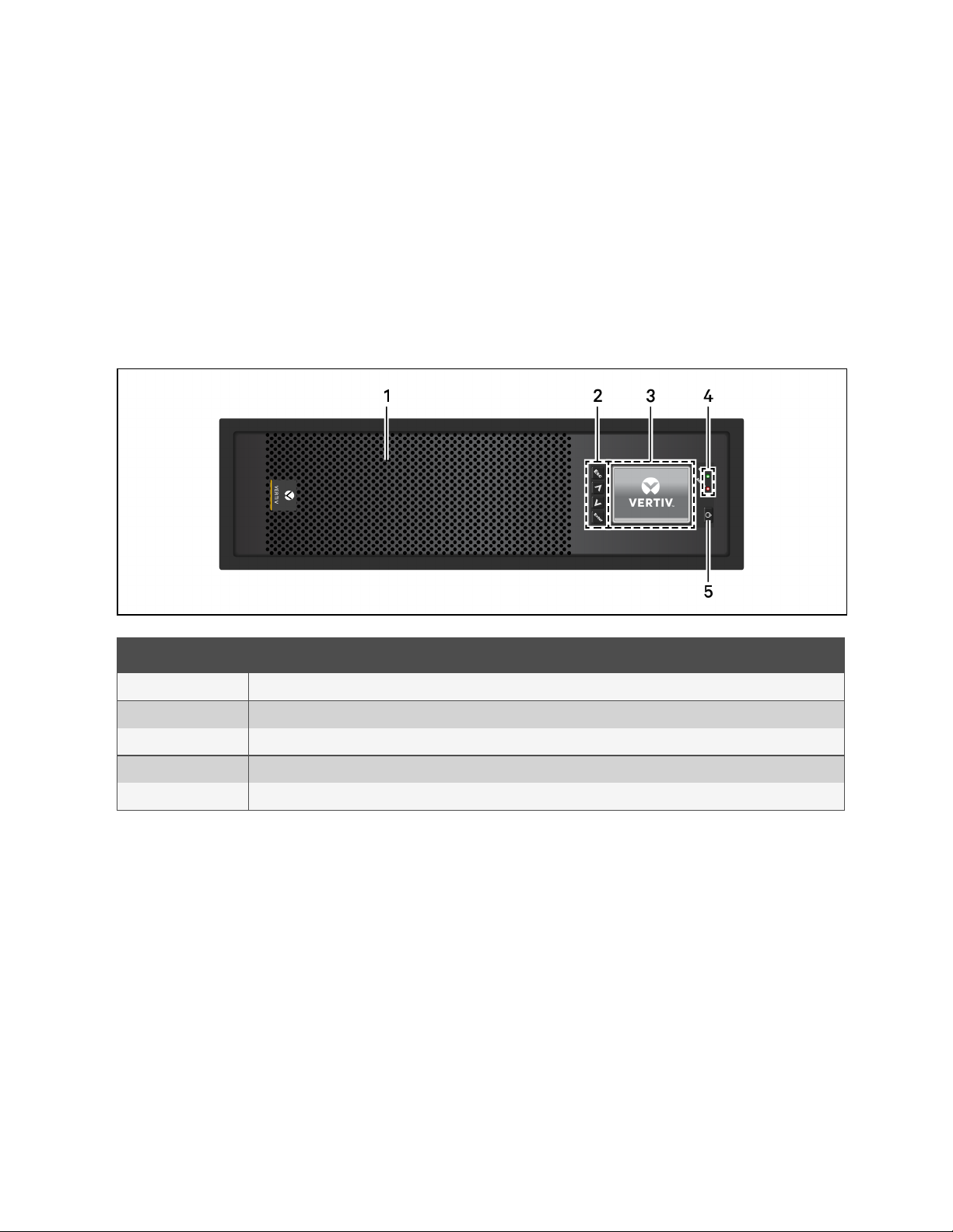
1.1 Front-panel Components
The front panel of the UPS provides ventilation holes and an operation/display panel with LED indicators and function keys.
Figure 1.1 Liebert® ITA2 UPS
Item Description
1 Ventilation holes
2 Menu keys, see 1.1 above .
3 LCDpanel. See Operation and Display Panel on page37 .
4 Run/Alarm indicator LEDs, see LED Indicators on page38 .
5 Power button, see 1.1 above .
1 Pr oduct Descri ption
3
Page 8
Vertiv™ Liebert® ITA2 Installer/User Guide
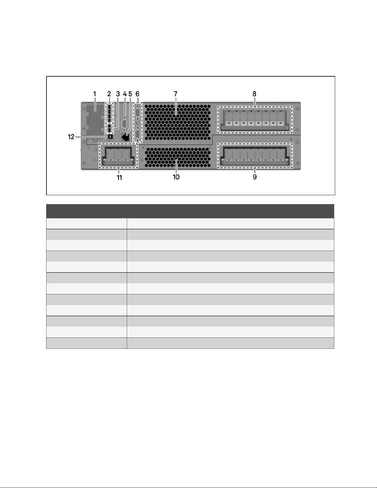
1.2 Rear Panel Components
Figure 1.2 UPS Rear Panel with Terminal Block Battery Connectors
Item Description
1 Vertiv™ Liebert® IntelliSlot™ port
2 Dry contac t port
3 REPO port
4 RS-232 port
5 Multi-functionport
6 Parallel/LBS ports
7 Ventilation holes
8 AC output terminals
9 AC input terminals
10 Ventilation holes
11 Battery input terminals
12 USB port
4
1 Pr oduct Descri ption
Page 9
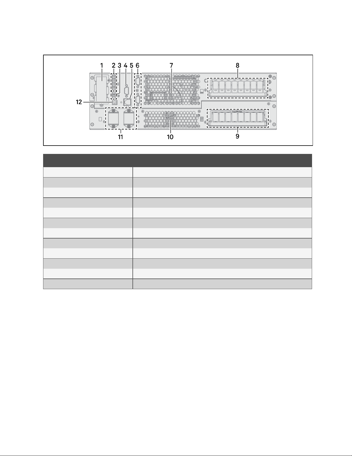
Figure 1.3 UPS Rear Panel with Plug-n-Play Battery Connectors
Item Description
1 Liebert®IntelliSlot™ port
2 Dry contac t port
Vertiv™ Liebert® ITA2 Installer/User Guide
3 REPO port
4 RS-232 port
5 Multi-functionport
6 Parallel/LBS ports
7 Ventilation holes
8 AC output terminals
9 AC input terminals
10 Ventilation holes
11 Battery-connector ports
12 USB port
1.3 UPS States and Operating Modes
NOTE: See Table 3.2 on page38 , for description of the run indicator and alarm indicator LED's mentioned in this
section.
1 Pr oduct Descri ption
5
Page 10
Vertiv™ Liebert® ITA2 Installer/User Guide
1.3.1 Normal Mode
Normal operation supplies clean, conditioned, sine wave power to connected equipment from normal utility input. The
battery charger charges the batteries. On the front panel display, the run indicator (green)is On, the alarm indicator is Off
and the buzzer is silent.
Figure 1.4 Normal Mode Operation
6
1 Pr oduct Descri ption
Page 11
Vertiv™ Liebert® ITA2 Installer/User Guide
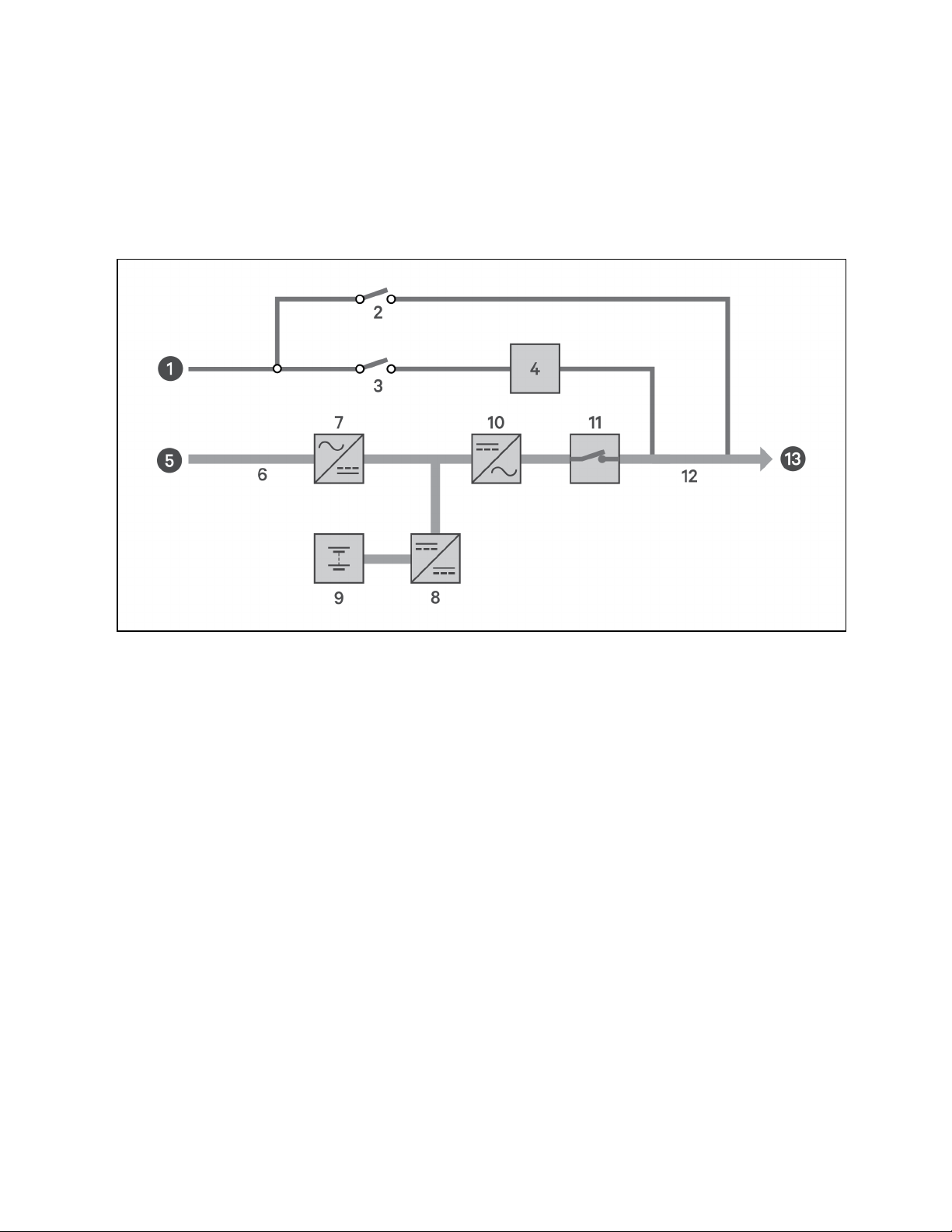
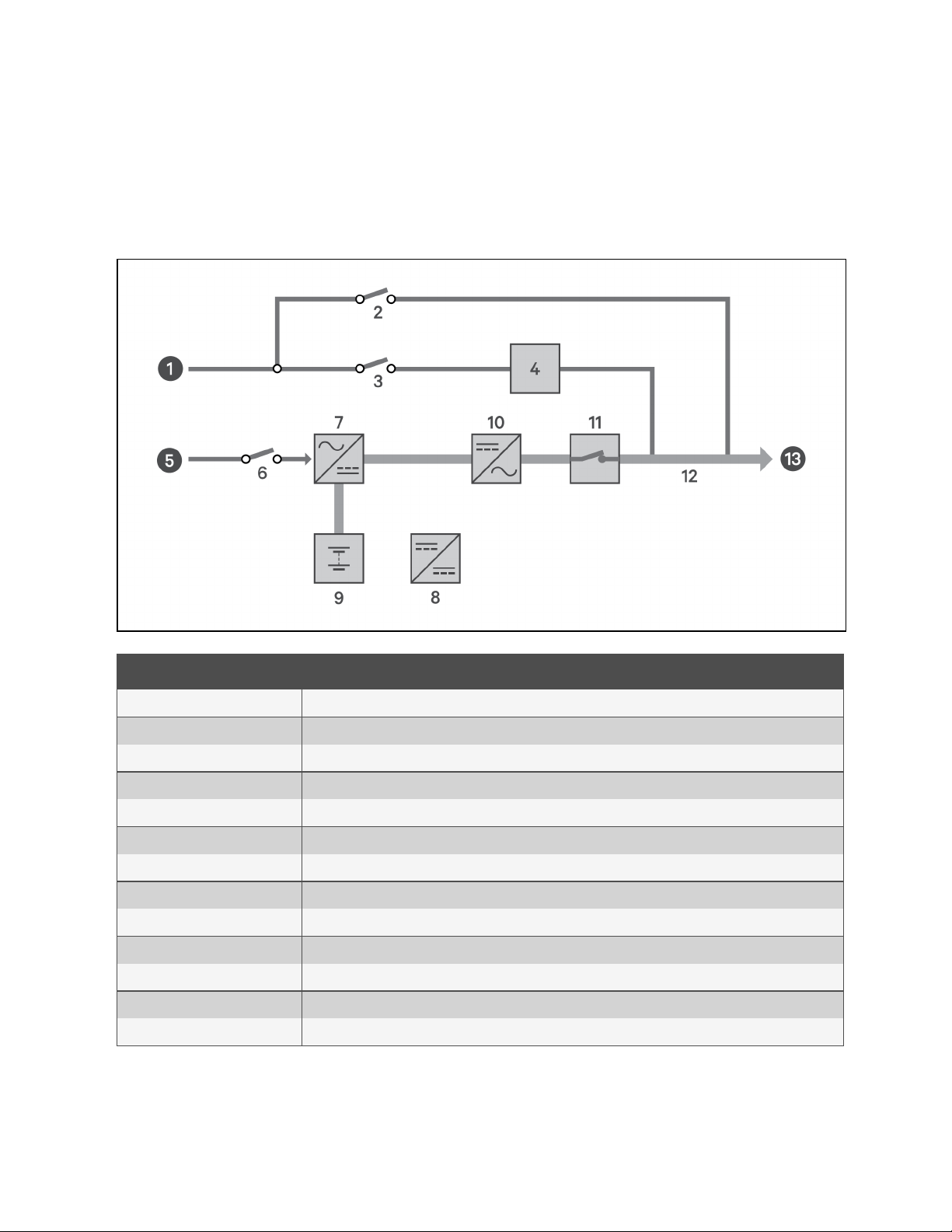
1.3.2 Battery Mode
Battery Mode supplies battery power to the load if utility power fails or if the utility voltage goes outside of the permissible
range. On the front panel display, the run indicator (green) is On, the alarm indicator (yellow)is On, and the buzzer beeps
once each second. The LCD "Current" screen displays "On Battery."
Figure 1.5 Battery Mode Operation
Item Description
1 Bypass input
2 Maintenance bypass breaker (MBB )
3 Bypass input breaker (BIB)
4 Static switch
5 Rectifier input
6 Rectifier input breaker (RIB)
7 Rectifier
8 Battery charger
9 Battery
10 Inverter
11 Automatic inverter switch
12 Maintenance isolation breaker (MIB)
13 UPSoutput
1 Pr oduct Descri ption
7
Page 12
Vertiv™ Liebert® ITA2 Installer/User Guide
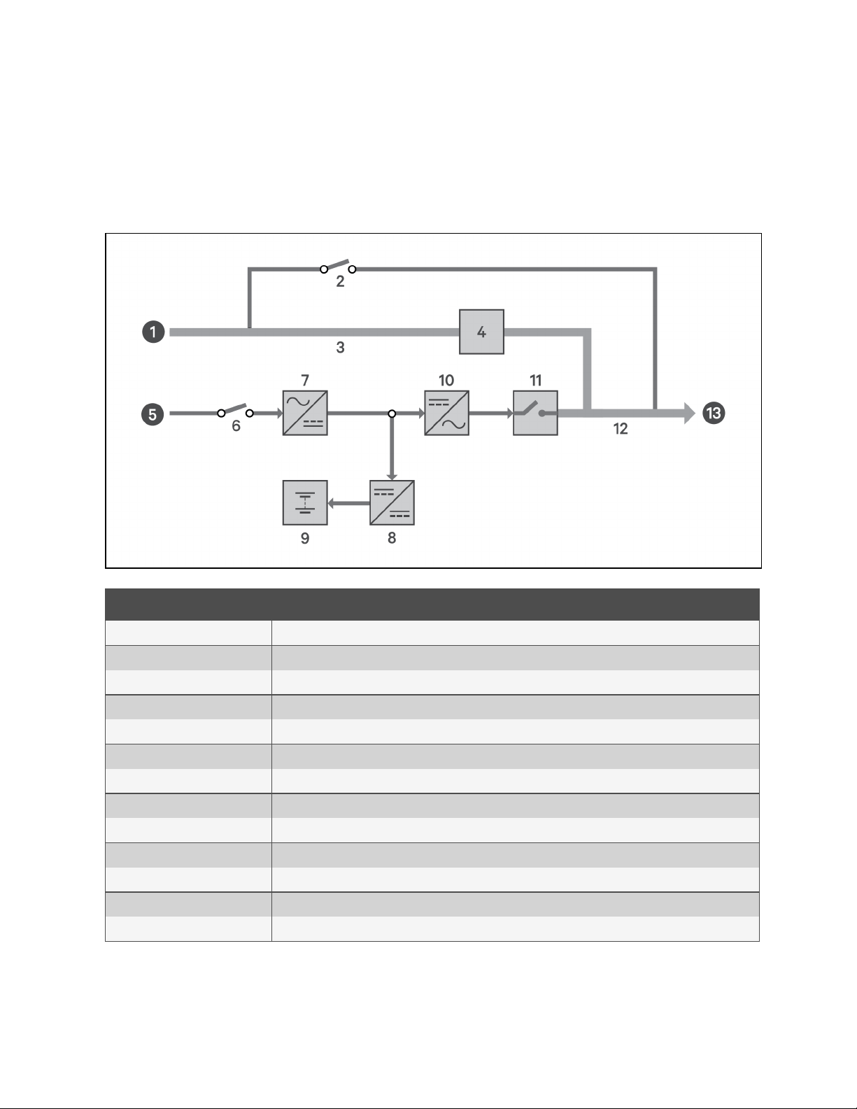
1.3.3 Bypass Mode
Bypass Mode supplies power to the load from the bypass source if an overload or fault occurs during normal operation. On
the front panel display, the run indicator (green) is On, the alarm indicator (yellow)is On, and the buzzer beeps once each
second. The LCD "Current" screen displays "On Bypass."
Figure 1.6 Bypass Mode Operation
Item Description
1 Bypass input
2 Maintenance byass breaker (MBB )
3 Bypass input breaker (BIB)
4 Static switch
5 Rectifier input
6 Rectifier input breaker (RIB)
7 Rectifier
8 Battery charger
9 Battery
10 Inverter
11 Automatic inverter switch
12 Maintenance isolation breaker (MIB)
13 UPSoutput
8
1 Pr oduct Descri ption
Page 13

Vertiv™ Liebert® ITA2 Installer/User Guide
1.3.4 Auto Restart Mode
When enabled, which is the default setting, Auto Restart Mode automatically restarts the UPS after a shutdown that resulted
from depleted batteries after an extended power outage. A built-in 10-second delay after utility power is restored allows
other equipment to start first and stabilize before the UPS restarts.
1.3.5 Fault State
When the UPS is in Normal Mode and the inverter fails or UPS overtemperature occurs, operation transfers to Bypass Mode.
When the UPS is in Battery Mode (with no bypass utility), and the inverter fails or overtemperature occurs, the UPS shuts
down and stops output power. During a fault state, the front panel display alarm indicator (red)is On, the buzzer beeps
continuously, and fault information displays on the LCD.
1.3.6 Maintenance Bypass Mode
Used when the UPS requires maintenance or repair, Maintenance Bypass Mode operation powers the connected equipment
with utility power while electrically isolating the internal UPS components.
The optional Liebert® ITA2 Maintenance Bypass Cabinet (MBC) is required for this mode. If your system includes a Liebert
ITA2 MBC, refer to the Liebert ITA2 MBC Installer/User Guide, available on the product page at www.Vertiv.com.
NOTICE
Risk of power interruption. Can damage the connected equipment.
If utility power fails or if its quality is out of range while the UPS is in Maintenance Bypass Mode, the UPS may
shut down without notice and shut off output power to the load.
NOTE: The UPS has no user-serviceable parts. If the UPS malfunctions and requires service, visit
http://www.Vertiv.com/en-us/support/ or contact your local Vertiv™ representative.
1.3.7 Start up on Bypass Mode
Default : Disabled. When the inverter is in the soft start stage, the bypass mode will not be automatically triggered.
Change the startup on bypass via Paramset or the LCD settings page to enable.
When the DC bus soft start is completed, the bypass mode will be automatically triggered. If the inverter can enter the soft
start stage and the soft start is completed, the ups will automatically switch from bypass mode to normal mode.
When the DC bus soft start is completed, the bypass mode will be automatically triggered. If the inverter can not
automatically enter the soft start phase, the ups will always operate in the bypass mode.
1 Pr oduct Descri ption
9
Page 14

Vertiv™ Liebert® ITA2 Installer/User Guide
This page intentionally left blank
10
1 Pr oduct Descri ption
Page 15

Vertiv™ Liebert® ITA2 Installer/User Guide
2 Installation
Installation must be performed by properly trained and qualified personnel. Do not start the UPS until after the installation is
finished and the system is commissioned by an authorized engineer.
WARNING! Risk of electrical shock. Can cause property damage, injury, and death. The unit has several
circuits that are energized with high DC and AC voltages. Check for voltage with both AC and DC voltmeters
before making contact and before working within the UPS. Only properly trained and qualified personnel
wearing appropriate, OSHA-approved personal protective equipment (PPE) should prepare for installation,
install and maintain the equipment. When performing maintenance with any part of the equipment under
power, service personnel and test equipment must stand on rubber mats.
WARNING! Risk of electrical shock. Can cause equipment damage, injury and death. Before beginning
installation, verify that all external overcurrent protection devices are open (Off), and that they are locked out
and tagged appropriately to prevent activation during the installation. After the power cables are connected,
the terminal block’s protective cover must be reinstalled to remove the electric shock hazard.
WARNING! Risk of heavy unit falling. Improper handling can cause equipment damage, injury, and death.
Exercise extreme care when handling unit cabinets and rack-mounted units to avoid equipment damage or
injury to personnel. The UPS weighs approximately 50.7lb. (23kg).
NOTE: The UPS can be connected to 3-phase, 5-wire (A, B, C, N, PE) TN, TT and IT AC power distribution system
(IEC60364-3).
2.1 Pre-Installation Preparation
Before beginning the installation, consider the environmental requirements, service clearances and external protective
devices for installing the equipment.
2.1.1 Environment of Installation Area
Install the UPS in a clean, well-ventilated environment with the ambient temperature within the specifications listed in 6 on
page57 .
The environment must:
• Have convenient wiring.
• Have adequate access for operators.
• Be clean and well-ventilated.
• Be free from water, heat source and flammable and explosive substances.
• Be free from dust, volatile gases and corrosive materials.
• Comply with local fire codes.
2 In stallation
11
Page 16
Vertiv™ Liebert® ITA2 Installer/User Guide
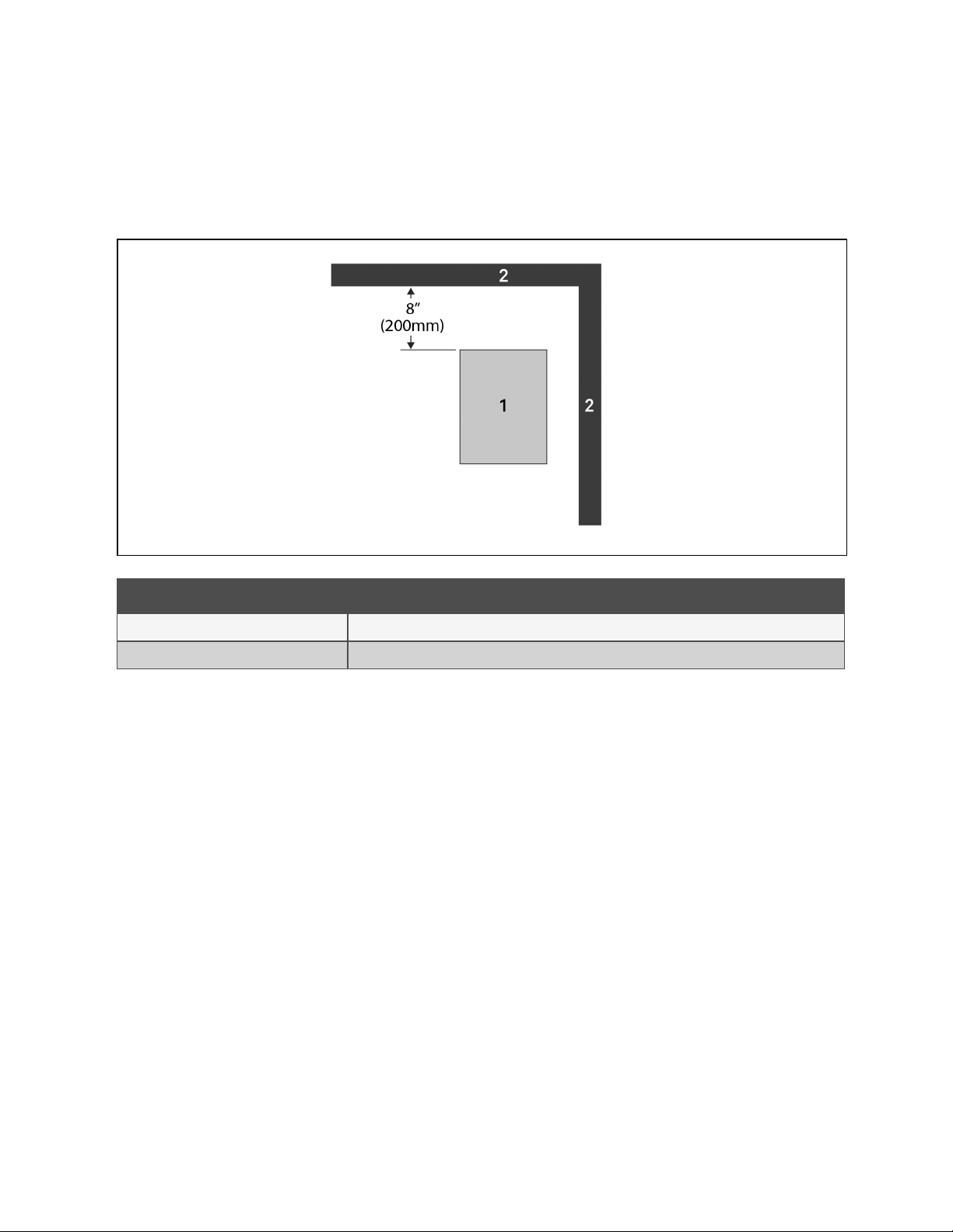
2.1.2 Installation Clearances
Internal fans provide forced-air cooling for the UPS. Cooling air enters through the front panel and hot air is exhausted
through the back. Maintain at least 8 in.(200mm) in the front and rear of the UPS, see Figure 2.1 below .
Figure 2.1 Required Clearances
Item Description
1 UPS (top view).
2 Wall or other solid surface.
2.1.3 Installation Tools
IMPORTANT! All tools used to install and maintain the ITA2 UPS and equipment must be insulated.
The following tools are required to properly install your UPS:
• Torque Wrench
• Slotted screwdriver
• Multimeter
• #3 Phillips-head screwdriver
• T10 Torx screwdriver
12
2 In stallation
Page 17

Vertiv™ Liebert® ITA2 Installer/User Guide
2.1.4 Storage
If you do not install the UPSimmediately, you must store it indoors and protect it from excessive moisture, heat and other
harsh conditions. Store the batteries in a dry, well-ventilated environment with a temperature range of 68°F ~ 77°F (20°C ~
25°C).
NOTICE
Risk of failure to properly charge batteries. Can damage the batteries and void the warranty.
Batteries will lose charge during storage. Batteries must be recharged as recommended by the battery
manufacturer every 3 to 6 months, depending on the storage temperature:
• At 68-77°F (20-25°C): charge after 6 months in storage
• At 78-86°F (26-30°C): charge after 3 months in storage
• At 87°F or higher (31°C or higher): charge after 1 month in storage.
2.1.5 External Protective Devices
Circuit breakers and other external protective devices must be installed on the UPS input. The following sections provide
general guidance for installation by properly trained and qualified personnel.
Rectifier and Bypass Input Protection
Overcurrent Protection—Install an appropriate overcurrent protective device should on the utility input power distribution.
Consider the current capacity of power cables and the system-overload requirements in selection of the input protection
and wiring, see Table 2.1 on page18 , and Table 2.2 on page19 .
Dual-Input System Protection—In a dual-input system, install separate protective devices for the utility and bypass at the
utility input power distribution.
Utility/Bypass Back-Feed Protection—The UPS includes back-feed protection in the event of a fault.
Earth Leakage Current—The residual current detector (RCD) for the UPS upstream input power distribution should be:
• Sensitive to the DC unidirectional pulse (Level A) in the power distribution network
• Insensitive to the transient current pulse
• General sensitivity type, settable: 0.3A ~ 1A
The residual current circuit breaker (RCCB) must be sensitive to the DC unidirectional pulse (Level A) in the power
distribution network, but insensitive to the transient current pulse, see Figure 2.2 below .
Figure 2.2 RCCB symbols
2 In stallation
When using the earth RCD in a split-bypass system, the RCD should be installed at the upstream input power distribution
end to prevent false alarms.The earth leakage current fed by the RFI filter in the UPS ranges from 3.5mAto100mA.
Vertiv™ recommends that you verify the sensitivity of each differential device of the upstream input power distribution and
downstream power distribution (to load).
13
Page 18

Vertiv™ Liebert® ITA2 Installer/User Guide
Battery
The UPS includes an overcurrent protection device for the battery.
UPS Output
The UPS includes output overcurrent protection in all modes of operation. If the customer-provided output distribution
panel is not within sight of the UPS, the distribution panel must include a main breaker.
2.2 Equipment Handling and Unpacking
WARNING! Risk of heavy unit falling. Improper handling can cause equipment damage, injury, and death.
Exercise extreme care when handling unit cabinets and rack-mounted units to avoid equipment damage or
injury to personnel. The UPS weighs approximately 50.7lb. (23kg).
During unpacking:
• Inspect the UPS for damage. If you find any problem, file a damage claim with the carrier immediately and
send a copy to Vertiv at:
Attn: Traffic Department
Vertiv Corporation
1050 Dearborn Drive
P.O. Box 29186
Columbus, Ohio 43085 USA
• Check the accessories and model numbers against the delivery list. If you find any problem, notify your local
Vertiv representative immediately.
2.3 Tower Installation
NOTE: The UPS may be installed with a maintenance bypass cabinet (MBC) or battery cabinets. If so, install the MBC
and battery cabinets before installing the UPS.
14
2 In stallation
Page 19
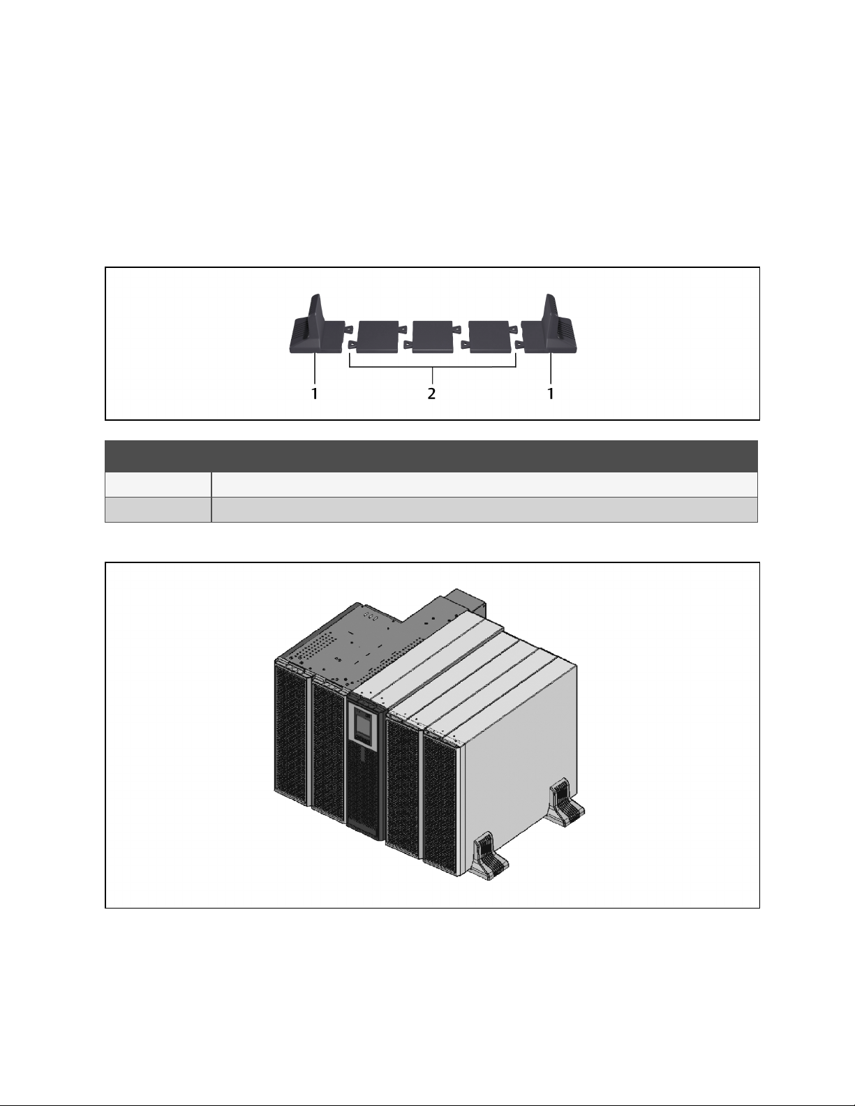
1. Take the support bases out of the accessories box.
2. If battery cabinets will be connected, take out the spacers that shipped with the battery cabinet.
3. If an MBC will be connected, take out the spacers shipped with the accessories.
4. Connect the spacers and the support bases as shown in Figure 2.3 below . Each tower assembly requires
twosupport base/spacer assemblies, one in the front and one in the rear.
5. Place the UPS, battery cabinets and the MBC on the twosupport base assemblies.
Figure 2.3 Support Bases
Vertiv™ Liebert® ITA2 Installer/User Guide
Item Description
1 Support bases
2 Spacers with connectors
Figure 2.4 Tower-Mounted Liebert® ITA2 UPS System with Battery Cabinets and MBC
2 In stallation
15
Page 20

Vertiv™ Liebert® ITA2 Installer/User Guide
2.4 Rack Installation
NOTICE
Risk of improper transport. Can cause damage to the UPS, MBC or battery cabinets.
Never attempt to lift or move the UPS, MBC or battery cabinets with the rack brackets. The brackets and
screws are not meant to lift the units.
NOTICE
Risk of improper installation. Can make rack top-heavy and cause a tipping hazard.
The battery cabinets are heavier than the UPS. Vertiv™ recommends installing the battery cabinets as near the
bottom of the rack as possible to maintain a low center of gravity. Install the UPS above the battery cabinets.
Install each unit on its own set of rack-mount guide rails. The rail kit will support the weight of a single UPS,
MBC or battery cabinet.
NOTE: The UPS may be installed with a maintenance bypass cabinet (MBC) or battery cabinets. If so, install the MBC
and battery cabinets before installing the UPS.
To mount the unit in the rack:
NOTE: Install the battery cabinets from bottom to top to minimize tipping hazard.
1. Referring to Figure 2.5 on the facing page , use four of the M4×10 screws on each bracket, and attach a
bracket to each front corner.
2. Referring to Figure 2.5 on the facing page , mount the right and left guide rails for the UPS and each battery
cabinet:
• Adjust the length of each guide rail to the dimensions of the rack.
• Align the install holes on the ends of the rail to the square holes in the rack, and use four of the provided
screws, two on each end to attach the rail to the rack.
3. Place the unit on the guide rails and push it completely into the rack along the guide rails.
4. Use M5×16 screws to secure the unit brackets to the rack, see Figure 2.5 on the facing page .
16
2 In stallation
Page 21
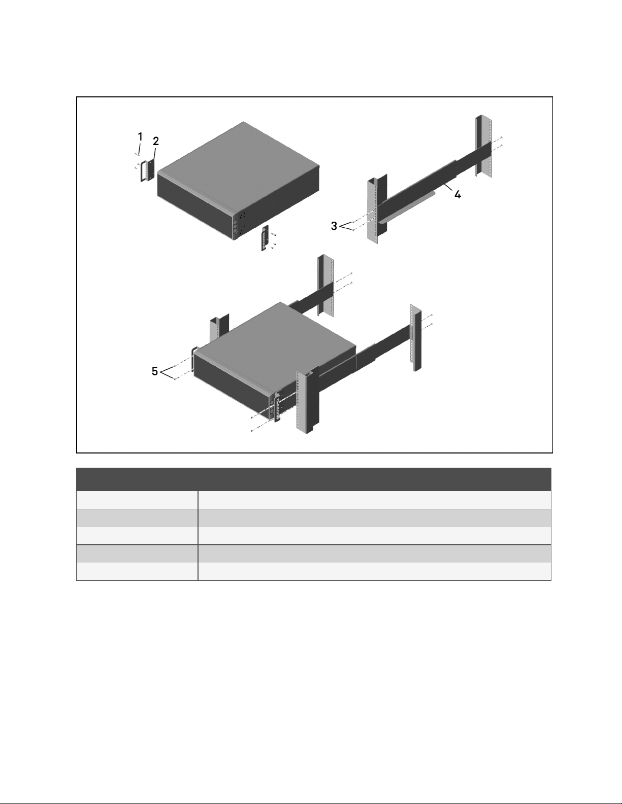
Figure 2.5 Guide Rail and Rack Bracket Installation
Vertiv™ Liebert® ITA2 Installer/User Guide
2 In stallation
Item Description
1 Bracket screw, four per bracket
2 Bracket, two
3 Rail screw, four per rail
4 Guide rail, one per side
5 Rac k-mount screw, four per bracket
17
Page 22
Vertiv™ Liebert® ITA2 Installer/User Guide
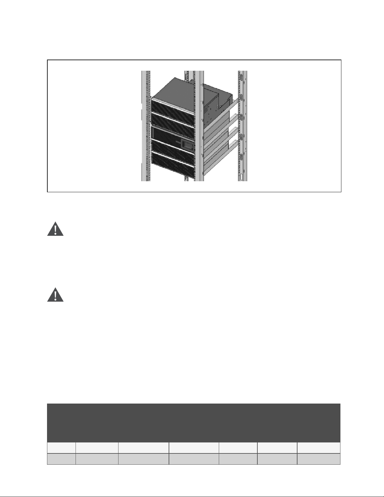
Figure 2.6 Rack-Mounted Liebert® ITA2 UPS System with Battery Cabinets and MBC
2.5 Connecting Power Cables
WARNING! Risk of electrical shock. Can cause property damage, injury and death. The unit has several
circuits that are energized with high DC and AC voltages. Check for voltage with both AC and DC voltmeters
before making contact and before working within the UPS. Only properly trained and qualified personnel
wearing appropriate, OSHA-approved personal protective equipment (PPE) should prepare for installation,
install and maintain the equipment. When performing maintenance with any part of the equipment under
power, service personnel and test equipment must stand on rubber mats.
WARNING! Risk of electrical shock. Can cause equipment damage, injury and death. Before beginning
installation, verify that all external overcurrent protection devices are open (Off), and that they are locked out
and tagged appropriately to prevent activation during the installation. After the power cables are connected,
the terminal block’s protective cover must be reinstalled to remove the electric shock hazard.
When connecting input and output cables, follow national and local wiring regulations, take the environment into account
and refer to NFPA70, Table310-16. The recommended minimum cables and overcurrent protection are listed in Table 2.1
below , and Table 2.2 on the facing page . The values are based upon an 86°F(30°C)ambient temperature.
The UPS has two modes of output power distribution, self-distribution and via the optional maintenance bypass cabinet.
These steps describe self-distribution mode connections. The connections for maintenance bypass power distribution are
included with the installation instructions for the ITA2 MBC.
Table 2.1 Currents and Wire Size—UPS Rectifier Input
Unit Rating
8kVA 24 30 8AWG 8AWG 10AWG 30lb-in.
10kVA 37 50 6AWG 6AWG 10AWG 30lb-in.
18
Maximum Current,
Amps
Recommended OPD,
Amp Trip
75°C THW
Copper Wire (ph ase)
Numb er of Cables per
Phase: 1
75°C THW
Copper Wire
(neutral)
Numb er of
Cables: 1
75°C THW
Copper Wire
(Ground)
Numb er of
Cables: 1
Recommended
Torque
2 In stallation
Page 23
Table 2.2 AC Currents and Wire Size—UPS Bypass Input* and Output
Vertiv™ Liebert® ITA2 Installer/User Guide
Unit Rating
8kVA 23 30 10AWG 10AWG 10AWG 30lb-in.
10kVA 28 40 8AWG 8AWG 10AWG 30lb-in.
Maximum Current,
Amps
* Bypass input for dual-input configurationsonly.
Recommended OPD,
Amp Trip
75°C THW
Copper Wire (ph ase)
Numb er of Cables per
Phase: 1
75°C THW
Copper Wire
(neutral)
Numb er of
Cables: 1
75°C THW
Copper Wire
(Ground)
Numb er of
Cables: 1
Table 2.3 Ring Terminal Part Numbers
AWG (mm2)
10 (5.26) 8 (8.36) 6 (13.3)
McMaster-Carr: 7113K462 McMaster-Carr: 7113K444 McMaster-Carr: 711 3K366
Manufacturer Part#
Thomas & Betts: RC1 0-14 Thomas & Betts: RDV71 7 Thomas & Betts: RE6-14
Tyco Electronics: 1 577648-1 Ty co Electronics: 132331-1 —
2.5.1 Connecting a Single-Input Configuration
WARNING! Risk of electrical shock. Can cause equipment damage, injury and death. Before beginning
installation, verify that all external overcurrent protection devices are open (Off), and that they are locked out
and tagged appropriately to prevent activation during the installation. After the power cables are connected,
the terminal block’s protective cover must be reinstalled to remove the electric shock hazard.
Recommended
Torque
1. Prepare for connection by removing the conduit box cover, opening knockout holes and routing cables through
the conduit.
2. Leave the shorting busbars in place on the UPS input terminal block.
3. Refer to the single-input terminal block illustrated in Figure 2.7 on page21 , and connect the cables from the
upstream feeder panel:
• Phase A to L1
• Phase B to L2
• Phase C to L3
• Neutral to N
• Ground to PE (next to pA)
NOTE: The UPS has two output terminal block sections, “always on” and “programmable/controllable.” The always on
connections are listed first, and the programmable connections are inside parentheses.
4. For output connections, refer to Figure 2.7 on page21 , and connect the cables from the UPS to the
downstream feeder panel on the panelboard main breaker:
• A (pA) to PhaseA
• B (pB) to PhaseB
• C (pC) to PhaseC
• Neutral N (N) to neutral bus
• Ground from PE (stud next to C) to the ground bus
2 In stallation
19
Page 24

Vertiv™ Liebert® ITA2 Installer/User Guide
5. Torque all customer-side connections per recommendations in Table 2.1 on page18 , and Table 2.2 on the
previous page
6. Replace the conduit box cover and secure it.
20
2 In stallation
Page 25

Figure 2.7 Single- and Dual-Input Configuration Wiring Diagram
Vertiv™ Liebert® ITA2 Installer/User Guide
Item Description
1 AC output terminal block
2 Single-input configuration terminal block
3 Dual-input configuration terminal block
4 PE (Ground)
5 C, output phase C
6 B, output phase B
7 A, output phase A
8 N, output neutral
9 pC, output phase C
10 pB, output phase B
11 pA, output phase A
12 L1, input phase A
13 L2, input phase B
14 L3, inputphase C
15 rA, rectifier input A
16 ba, bypass input A
2 In stallation
17 rB, rectifier input B
21
Page 26

Vertiv™ Liebert® ITA2 Installer/User Guide
Item Description
18 bB, bypass input B
19 rC, rectifier input C
20 bC, bypass input C
21 Battery cable connector
2.5.2 Connecting a Dual-input Configuration
WARNING! Risk of electrical shock. Can cause equipment damage, injury and death. Before beginning
installation, verify that all external overcurrent protection devices are open (Off), and that they are locked out
and tagged appropriately to prevent activation during the installation. After the power cables are connected,
the terminal block’s protective cover must be reinstalled to remove the electric shock hazard.
1. Prepare for connection by removing the conduit box cover, opening knockout holes and routing cables through
the conduit.
2. Remove the shorting busbars from the terminals labeled L1, L2, and L3 in Figure 2.7 on the previous page .
3. For the rectifier input, refer to the dual-input terminal block in Figure 2.7 on the previous page , and connect
the cables from the upstream feeder panel:
• Phase A to rA
• Phase B to rB
• Phase C to rC
• Neutral to N
• Ground to PE (next to pA).
4. For the bypass input, refer to the dual-input terminal block in Figure 2.7 on the previous page , and connect
the cables from the upstream feeder panel:
• Phase A to bA
• Phase B to bB
• Phase C to bC
• Neutral to N
• Ground to PE (next to pA).
NOTE: The UPS has two output terminal block sections, “always on” and “programmable/controllable.” The always on
connections are listed first, and the programmable connections are inside parentheses.
5. For output connections, refer to Figure 2.7 on the previous page , and connect the cables from the UPS to the
downstream feeder panel on the panelboard main breaker:
• A (pA) to PhaseA
• B (pB) to PhaseB
• C (pC) to PhaseC
• N (N) to the neutral bus
• Ground from PE (stud next to C) to the ground bus
6. Torque all customer-side connections per recommendations in Table 2.1 on page18 , and Table 2.2 on
page19
7. Replace the conduit box cover and secure it.
22
2 In stallation
Page 27

2.6 Connecting a Single Battery Cabinet System
Do not reverse the polarity of the battery cables.
2.6.1 Connecting the Cables
WARNING! Risk of electrical shock. Can cause property damage, injury and death. The unit has several
circuits that are energized with high DC and AC voltages. Check for voltage with both AC and DC voltmeters
before making contact and before working within the UPS. Only properly trained and qualified personnel
wearing appropriate, OSHA-approved personal protective equipment (PPE) should prepare for installation,
install and maintain the equipment. When performing maintenance with any part of the equipment under
power, service personnel and test equipment must stand on rubber mats.
WARNING! Risk of electrical shock. Can cause equipment damage, injury and death. Before beginning
installation, verify that all external overcurrent protection devices are open (Off), and that they are locked out
and tagged appropriately to prevent activation during the installation. After the power cables are connected,
the terminal block’s protective cover must be reinstalled to remove the electric shock hazard.
Vertiv™ Liebert® ITA2 Installer/User Guide
WARNING! Risk of heavy unit falling. Improper handling can cause equipment damage, injury, and death.
Exercise extreme care when handling unit cabinets and rack-mounted units to avoid equipment damage or
injury to personnel. The UPS weighs approximately 50.7lb. (23kg).
The factory-provided, UPS-to-battery power cable, see Figure 2.8 below , connects to Connector A on both battery
cabinets in a single/first battery string. The battery-to-battery power cable connects additional battery strings/cabinets, see
Connecting Additional Battery Cabinet Systems on page29 .
Figure 2.8 Power Cables
2 In stallation
Item Description
1 UPS-to-battery cable (for hard-wiredconfigurations)
2 Battery-to-battery cable (alsoUPS-to-battery for plug-and-play configurations)
23
Page 28

Vertiv™ Liebert® ITA2 Installer/User Guide
To connect the UPS with terminal block connections to the battery cabinet system:
1. Make sure the battery breaker on the rear of the cabinet is open (Off).
2. Connect the ring terminals of the UPS-to-battery cable to the rear of the UPS.
3. Install the insulating plates on the battery terminals, see Figure 2.9 below :
a. Connect the ground wire (PE) to the ground screw on the rear of the UPS.
b. Place the battery-cable ring lug on the terminal block, add the insulating plate, then insert the screw and
tighten to 30lb-in. torque.
c. Repeat Step b for each terminal block connection: battery+, battery neutral, and battery–.
Figure 2.9 Battery Insulating Plates
4. Depending on the type of battery cabinet, see Figure 2.10 on page26 for 3U, or see Figure 2.11 on page28 ,
for 2U, and connect the other ends to Connector A on each of the battery cabinets in the string.
5. Connect the RJ-45 communication cable to the communication port on the UPS and the other end to
Communication Port 1 on the first battery cabinet.
• If connecting a 2U battery string, connect a cable between Comm Port 2 on the first cabinet, and Comm
Port 1 on the second.
6. For a single battery string, close the battery output breaker(s).
– or –
If installing additional battery strings (two battery cabinets each), proceed to Connecting Additional Battery
Cabinet Systems on page29 .
To connect the UPS with plug-n-play connectors to the battery cabinet system:
1. Make sure the battery breaker on the rear of the cabinet is open (Off).
2. Using a cable provided with the battery cabinet, refer to Figure 2.11 on page28 , and:
• Connect the end labeled "Port B" to one of the connectors on the rear of the UPS and tighten the securing
screws.
• Connect the end labeled "Port A" to Connector A on the battery cabinet.
3. Repeat Step 2 , for the second battery cabinet.
24
2 In stallation
Page 29

Vertiv™ Liebert® ITA2 Installer/User Guide
4. Using a communication cable with RJ-45 connectors, refer to Figure 2.11 on page28 , and:
• Connect one end to the multi-function port on the rear of the UPS.
• Connect the other end to one of the RJ-45 communication ports on the first battery cabinet.
• Connect another cable from the remaining RJ-45 communication port on the first battery cabinet to one
of the ports on the second battery cabinet.
5. For a single battery string, close the battery output breaker(s).
– or –
If you are installing additional battery strings (two battery cabinets each), proceed to Connecting Additional
Battery Cabinet Systems on page29 .
2 In stallation
25
Page 30

Vertiv™ Liebert® ITA2 Installer/User Guide
Figure 2.10 Cabling the UPS and Two 3U battery Strings in Parallel
Item Description
1 Ground screw (PE)
2 BAT – (negative) connector
3 BAT N (neutral) connector
4 BAT + (positive) connector
5 Communication portconnector (RJ-45)
6 Connector A
7 Communication port Connector 1
8 Communication portConnector 2
9 Connector B
10 Battery Cabinet 4
26
2 In stallation
Page 31

Item Description
11 B attery Cabinet 3
12 B attery String 2
13 Battery Cabinet 2
14 Battery Cabinet 1
15 Battery String 1
16 UPS
17 Communication cable, UPS to Comm Port 1 on Battery Cabinet 1
18 UPS-to-battery power cable, to Connector A on B attery Cabinets 1 and 2
19 Communication cable, Comm Port 2 to Comm Port 1 on Battery Cabinet 3
20 Battery-to-battery power cable, Battery Cabinet 1 Connector B to Connector A on Ba ttery Cabinet 3
21 B attery-to-battery power cable, Battery Cabinet 2 Connector B to Connector A on Battery Cabinet 4
Vertiv™ Liebert® ITA2 Installer/User Guide
2 In stallation
27
Page 32

Vertiv™ Liebert® ITA2 Installer/User Guide
Figure 2.11 Cabling the UPS and Two 2U Battery Strings in Parallel
Item Description
1 Battery cable connectors
2 Multi-function connector (RJ-45)
3 Communication port connector (RJ-45)
4 Communication port connector (RJ-45)
5 Connector B
6 Connector A
7 DIPswitch
8 Battery Cabinet 4
9 Battery Cabinet 3
10 Battery String 2
11 Battery Cabinet 2
12 B attery Cabinet 1
28
2 In stallation
Page 33

Item Description
13 Battery String 1
14 UPS
15 Comm unication cable, UPS to communication port on Battery Cabinet 1
16 Battery cable to Connector A on Battery Cabinet 1 and 2
20 Communication cable between communication portson each battery cabinet.
21 B attery cable from Connector B on Battery Cabinet 1 to Connector A on Ba ttery Cabinet 3
22 Battery cable from Connector B on Battery Cabinet 2 to Connector A on Battery Cabinet 4
2.7 Connecting Additional Battery Cabinet Systems
WARNING! Risk of electrical shock. Can cause property damage, injury and death. The unit has several
circuits that are energized with high DC and AC voltages. Check for voltage with both AC and DC voltmeters
before making contact and before working within the UPS. Only properly trained and qualified personnel
wearing appropriate, OSHA-approved personal protective equipment (PPE) should prepare for installation,
install and maintain the equipment. When performing maintenance with any part of the equipment under
power, service personnel and test equipment must stand on rubber mats.
Vertiv™ Liebert® ITA2 Installer/User Guide
WARNING! Risk of electrical shock. Can cause equipment damage, injury and death. Before beginning
installation, verify that all external overcurrent protection devices are open (Off), and that they are locked out
and tagged appropriately to prevent activation during the installation. After the power cables are connected,
the terminal block’s protective cover must be reinstalled to remove the electric shock hazard.
WARNING! Risk of heavy unit falling. Improper handling can cause equipment damage, injury, and death.
Exercise extreme care when handling unit cabinets and rack-mounted units to avoid equipment damage or
injury to personnel. The UPS weighs approximately 50.7lb. (23kg). The battery cabinets weigh
approximately 115lb(52.2kg)
The factory-provided, battery-to-battery power cables, see Figure 2.8 on page23 , connect the battery strings in parallel
to extend the backup time of the UPS. For 2U battery cabinets, you must adjust the DIP switch on the rear panel for each
cabinet in the string.
2 In stallation
29
Page 34

Vertiv™ Liebert® ITA2 Installer/User Guide
To connect power cables:
1. Verify that the battery breakers are in the open (Off) position before connecting or disconnecting battery
cables.
2. Depending on the type of battery cabinet, see Figure 2.10 on page26 , for 3U or Figure 2.11 on page28 , for
2U, and:
• Connect one end of a battery-to-battery cable to Connector B on the first cabinet in the first string
(Battery Cabinet 1), and the other end to Connector A on the first cabinet in the additional string (Battery
Cabinet 3).
• Connect one end of a battery-to-battery cable to Connector B on the second cabinet in the first string
(Battery Cabinet 2), and the other end to Connector A on the second cabinet in the additional string
(Battery Cabinet 4).
3. Verify that the connector colors align and press the cable in firmly to fully seat the connectors.
4. Tighten the captive screws on the extension cable to prevent the extension cable from loosening.
5. Connect an RJ-45 communication cable:
• On 3U strings, to Communication Port 2 on the first cabinet in the first string (Battery Cabinet 1), and the
other end to Communication Port 1 on the first cabinet in the additional string (Battery Cabinet 3).
• On 2U strings, connect a communication cable to Communication Port 2 and Communication Port 1
between each battery cabinet.
NOTE: If using both 2U and 3U battery cabinets in a system, you must manually configure the number of connected
battery strings via the display. The number of strings is not auto-detected.
NOTE: In a mixed-cabinet system, the communication cables allow temperature measurements. If your system is
running on an older version of firmware, you may need to set the multifunction port to "temperature" to enable the
measurements.
6. On 3U strings, close the battery output breaker(s).
– or –
On 2U strings, refer to Table 2.4 on the facing page , and Figure 2.12 on the facing page , and set the DIP
switch on both cabinets in each additional string before closing the battery output breaker(s).
NOTE: The settings for String 1 are the factory-default settings.
30
2 In stallation
Page 35

Table 2.4 DIP Switch Settings for2UBattery Cabinet Strings
DIP S witch Position
Vertiv™ Liebert® ITA2 Installer/User Guide
String Cabinet
1 2 3 4 5 6
A Off Off Of f Off Off On
1
B Off Off Off Off O n Off
A Off Off Of f Off On O n
2
B Off Off Off On Off Off
A Off Off Of f O n Off O n
3
B Off Off Off On On Off
A Off Off Of f O n On On
4
B Off Off On Off Off Off
A Off Off On Off Off On
5
B Off Off On Off On Off
Figure 2.12 DIP Switch on Rear Panel of 2U Battery Cabinet
Group Num
2 In stallation
Item Description
1 Group
2 Number
31
Page 36

Vertiv™ Liebert® ITA2 Installer/User Guide
2.8 Communication Connections
The communication ports include:
• Liebert® IntelliSlot™ card port
• RS-232 port
• I/O, programmable dry contacts
• REPO port
• Serial port
• USB port
• Multi-function port
2.8.1 Liebert IntelliSlot Ports
The UPS has one Liebert IntelliSlot port on the rearof the unit.
Table 2.5 below , describes the cards available. The instructions for configuring and using the cards are available at
www.Vertiv.com.
Table 2.5 Liebert IntelliSlot Communication Cards
Card Description
Liebert
IS-UNITY-DP
Card
Liebert
IS-Relay Card
Communicates with up to two third-party platforms including SNMP , Modbus, BACnet and YDN-23 protocols to network-connected
Vertiv m ontoring/shutdown applications or third-party shutdownsoftware.
Provides dry contact alarm information, including signals for: On Battery, On Bypass, LowB attery, Summary Alarm, UPS Fault and On
UPS for communication to a rem ote m onitoringsystem or network-connected Vertiv or third-party shutdown software. The ca rd also
accepts input signals to shut down the UPS during any operating mode.
32
2 In stallation
Page 37

Vertiv™ Liebert® ITA2 Installer/User Guide
2.8.2 REPO Connection
Table 2.6 below , describes the pin-out of the REPO port used for N.O. or N.C. connection.
Table 2.6 REPO Port Pin Descriptions
J14 Pin # Pin Name Description
9 +5VDC REPO Power Supply, 5 VDC, 100mA
10 REPO Coil N. C. Normally Closed circuit, EPO is activated when P in 9 – Pin 10 is opened
11 REPO Coil N.O. Normally Open circuit, EPO is activated when Pin 11 – Pin 12 is closed
12 GND REPO Circuit Ground
WARNING! Risk of electrical shock. Can cause equipment damage, injury and death. The EPO action of the
UPS will shut down the rectifier, inverter and static bypass, but it does not disconnect input power to the
UPS. To electrically isolate the UPS, disconnect the upstream input feeder breaker when generating the EPO.
Figure 1.2 on page4 , shows the location of the REPO connection on the UPS rear panel. Figure 2.13 on the next page ,
shows the connection details.
If a REPOconnection is not required for the UPS, the factory-installed jumper between Pin9 and Pin10 must remain
installed for the UPS to operate.
NOTE: The terminal block wire range is 18AWG ~ 22AWG (0.82mm2~ 0.33mm2), and we recommend using 18AWG
copper, shielded signal cable.
2 In stallation
33
Page 38

Vertiv™ Liebert® ITA2 Installer/User Guide
Figure 2.13 REPO Connections Detail
Item Description
1 No REPOconnection—Factory-supplied jumper must remain installed.
2 Normally closed (N.C.) c onnection—Remove factory-supplied jumper and wire P ins 2 and 4 to a remote switch.
3 Normally open (N. O.)connection—Factory-suppliedjumper must remain installed.
4 Port5/REPO input. See Table 2. 6 on the previous page , for the pin-out details.
2.8.3 Dry Contact Connections
The UPS includes five dry contact ports described in Table 2.7 on the facing page . The location of the ports is shown in
Figure 1.2 on page4 .
For Ports 1 to 4, the I/O dry contact port capacity is 125VAC, 0.5A; 30VDC, 1A
34
2 In stallation
Page 39

Table 2.7 Dry Contact Ports and Pin-Out
Port Number/Name Pin Number Pin Name Description
LOW_
1/Output Port 1
2/Output Port 2
BATTERY/ON_
BATTERY/ON_
1
2 GND Ground
3
BYPASS/UPS_
FAULT/Main
back-feed
protection
enabled
LOW_
BATTERY/ON_
BATTERY/ON_
BYPASS/UPS_
FAULT/ Bypass
back-feed
protection
enabled
Default: LOW_BATTERY, can be set via the LCD settings page. User can choose dry contact
as NO/NC. When N O (default) and there is an alarm active on the system, Pin 1 a nd Pin 2 are
shorted. When NC and there is an alarm active on the system, Pin 1 and Pin 2 are open. If then
user would like to change Dry contact function to “main backfeed” via P aramset or MCU, dry
contact status can only be NO, user can not choose dry contact a s NC due to main backfeed
function design logic.
Default: UPS_FAULT, can be set via the LCD settingspage. User can choose dry contact as
NO/NC. When NO (default) and there is an alarm active on the system, Pin 3 and Pin 4 are
shorted. When NC and there is an alarm active on the system, Pin 3 and Pin 4 are open. If then
user would like to change Dry contact function to “bypass backfeed” via Paramset or MCU,
dry contact status can only be NO, user can not choose dry contact as N C due to bypass
backfeed function design logic.
Vertiv™ Liebert® ITA2 Installer/User Guide
4 GND Ground
3/InputPort 1
4/Input Port 2
5/REPO Input Port
Battery Mode
shutdown/Any
5
6 GND Ground
7
8 GND Ground
9 +5V REPO power supply, 5VDC 100mA
10 REPO Coil-NC NC, EPO activated when Pin 9 and Pin 10 are open.
11 REPO Coil-NO Trigger REPO when Pin 11 and Pin 12 are closed.
12 GND REPO Ground
mode shutdown
(Remote Comms
Shutdown)/
Maintain mode
Battery mode
shutdown/Any
mode shutdown
(Remote Comms
Shutdown)/
Maintain mode
Default: Maintain mode, can be set via the LCD settings page and dry contact is NO by
default. User can not choose dry contact as NC. For Battery mode shut-downand any m ode
shut-down, user can choose dry contact as NO/NC. When N O (default), Pin 5 and Pin 6 are
shorted, the function is a ctive. When NC, Pin 5 and Pin 6 are open, the function is active.
When the Pin 5 and Pin 6 signal returns to the original state, the UPS will power on the inverter
automatically.
Default: Maintain mode, can be set via the LCD settings page and dry contact is NO by
default, User can not choose dry contact as NC. For Battery mode shut-downand Any mode
shut-down, User can choose dry contact as NO/NC. when NO (default), Pin 7 and Pin 8 are
shorted, the function is a ctive. When NC, Pin 7 a nd Pin 8 are open, the function is a ctive.
When the Pin 7 and Pin 8 signal returns to the original state, the UPS will power on the inverter
automatically.
2.8.4 Connecting USB Communication Cables
2 In stallation
A standard, USB Type B port is provided to connect to a computer or network server. The protocol is USB HIDfor Power
Devices.
2.9 Connecting Serial Port Communication Cables
To connect the serial port communication cable, connect one end of the DB-9 serial port communication cable to the DB-9
serial port on the rear panel of the UPS. Connect the other end to the computer’s DB-9 port. The port uses the RS-232
protocol.
35
Page 40

Vertiv™ Liebert® ITA2 Installer/User Guide
Table 2.8 DB-9F Pin-Out Description
Pin No. F unction
2 TX (Send data)
3 RX (Receive data)
5 Common
2.9.1 Connecting Multi-Function Port (RJ-45)
The multi-function port is a standard RJ-45 connection that supports Modbus/Jbus protocol, and on units with a terminal
block battery connector, it connects Vertiv™ temperature and temperature/humidity sensors. When connecting 2U battery
cabinets, you must use this port to automatically detect the number of battery strings and for temperature-compensated
charging. You can configure the port function using the Operation and Display panel.
36
2 In stallation
Page 41

Vertiv™ Liebert® ITA2 Installer/User Guide
3 Operation and Display Panel
The operation/display panel includes LED indicators, function keys, and an LCDinterface to configure and control UPS
operation.
Figure 3.1 UPS Front Panel Display
Table 3.1 Display Panel Button Functions and Descriptions
Button F unction Description
Enter Confirm or enter selection.
Up Move to previous page, increase value, mov e left.
Down Move to next page, decrease value, move right.
Escape Go back .
Power Power-on the UPS, power-off the UPS, transfer to Bypass Mode.
3 Op eration and Dis play Panel
37
Page 42

Vertiv™ Liebert® ITA2 Installer/User Guide
NOTE: While the UPS is operating, the LCD will dim and display a screen saver if there is no active alarm or user
interaction for 2 minutes, see Figure 3.2 below . If an alarm or fault occurs or if any button is pressed, the UPS-flow
screen displays.
Figure 3.2 LCD Screen Saver
3.1 LED Indicators
The LEDs on the front panel display indicate operation and alarm status of the UPS.
Table 3.2 LED Functions
Indicator LED Co lor LED State Indicates:
On UPS has output
Run Indicator Green
Yellow On Alarm occurs
Alarm Indicator
Red On Fault occurs
N/A Off No alarm, no fault
Blinking Inverter is starting
Off UPS has no output
3.2 Audible Alarm (Buzzer)
An audible alarm accompanies various events during UPS operation. Table 3.3 below , describes the sounds and their
meaning. To silence an alarm, see Silencingthe Audible Alarm on page49 .
Table 3.3 Audible Alarm Descriptions
Sou nd Indicates:
Continuous beep Generated when a UPS fault appears, such as a fuse or hardware failure.
One beep every 0.5 seconds Generated when a UPS critical ala rm appears, such as a n inverter overload.
One beep every 1 second Generated when a UPS critical alarm appears, such as on-battery low voltage.
One beep every 3.3 seconds Generated when a UPS general ala rm appears.
38
3 Op eration and Dis play Panel
Page 43

Vertiv™ Liebert® ITA2 Installer/User Guide
3.3 LCD Menu and Screens
The menu-driven LCD user interface lets you browse the UPS status, view operating parameters, customize settings, control
operation and view alarm/event history. Use the function keys to navigate through the menu, and view statuses or select
settings in the screens.
Figure 3.3 LCDMenu Structure
3.3.1 Startup and UPS Mimic Screens
At startup, the UPS executes a system test and displays the Vertiv™ logo screen for 10to15 seconds, shown in Figure 3.1
on page37 . After the test completes, an overview screen shows status information, the active (green) power path and the
non-working power path (gray).
Figure 3.4 UPS Mimic Screen
3 Op eration and Dis play Panel
39
Page 44

Vertiv™ Liebert® ITA2 Installer/User Guide
3.3.2 Main Menu
To access the Main Menu, press Enter while at the UPS Mimic screen. Use the Up/Down buttons to select the submenu
options, and press Enter to open the submenu. Press ESC to return to the UPSMimic.
Figure 3.5 Main Menu
Table 3.4 Menu Options
Subm enu D escription
Status Voltage, current, frequency and parameters for UPS components, see Status Screen below .
Settings Display and system parameter settings, see Settings Submenu on the facing page .
Control UPS controls, see Control Screen on page42 .
Log Current alarms and event history, see Log Screen on page42 .
About Product and network information, see About Page on page43 .
Maintain Service-only, proprietary, password-protected page for use only by Vertiv™ service representatives.
Status Screen
The Status Screen displays voltages, currents, frequencies and parameters on individual tabs for input, bypass, battery,
output and load status.
To view the UPS status information:
1. At the main menu, select the Status icon, and press Enter.
2. Use the arrow buttons to move the cursor left/right and select a tab, then press Enter to display the status
information for the selected tab.
40
3 Op eration and Dis play Panel
Page 45

Figure 3.6 Status Screen Tabs
Item Description
1 Screen tabs with Input tab selected.
Settings Submenu
Vertiv™ Liebert® ITA2 Installer/User Guide
The Settings Screen consists of tabs that list UPS settings described in Table 3.5 on page44 .
NOTE: To adjust the settings, you must enter a password. See Editing Display and Operation Settings on page43 , for
details on entering the password and editing the setting parameters.
Figure 3.7 Monitor and System tabs on the Settings Submenu
3 Op eration and Dis play Panel
41
Page 46

Vertiv™ Liebert® ITA2 Installer/User Guide
Control Screen
The Control Screen offers UPS-control options.
To adjust the UPS controls:
1. At the main menu, select the Control icon, and press Enter.
2. Use the arrow buttons to move the cursor to the option, then press Enter to selected the control.
Figure 3.8 Control Screen
Log Screen
Log Screen tabs list the current alarms and the alarm/event history.
To view the logs:
1. At the Main Menu, select the Log icon, and press Enter.
2. Use the arrow buttons to move the cursor left/right and select a tab, then press Enter to display the log for the
selected tab.
Figure 3.9 Current and History Log Tabs
42
3 Op eration and Dis play Panel
Page 47

About Page
The About Page tabs list information about the product and the network.
To view the product and network information:
1. At the Main Menu, select the Settings icon, and press Enter.
2. Use the arrow buttons to move the cursor left/right and select a tab, then press Enter to display the information
for the selected tab. The options available are described in Table 3.5 on the next page .
Figure 3.10 About Screen Tabs
Vertiv™ Liebert® ITA2 Installer/User Guide
3.4 Editing Display and Operation Settings
You may adjust the display settings and UPS configuration via the LCD. Table 3.5 on the next page , describes the
settings. The display and operation settings are password projected. The default password is 111111 (six ones).
NOTE: We recommend that you change the password to protect your system and equipment and record the new
password and store it in an accessible location for later retrieval. See Changing the Password on page46 .
To enter the password:
1. Press the up arrow button to change the digit, then press the down arrow button to move to the next digit.
2. Repeat to select each digit, and press Enter to submit the password.
Figure 3.11 Password Prompt
3 Op eration and Dis play Panel
43
Page 48

Vertiv™ Liebert® ITA2 Installer/User Guide
Table 3.5 Settings Available at the Display Panel
Tab Settings Parameter range Default setting
Auto restart Disable, Enable Enable
Auto restart delay 0 - 999 seconds 0
Guaranteed Shutdown Disable, Enable Disable
Remote Control Disable, Enable Enable
Remote Power O N delay 0 - 999 seconds 0
System
Output
Remote Shutdown delay 0 - 999 seconds 0
LBS Select Disable, Enable Disable
IT Earthing System Disable, Enable Disable
Dry Contact 1 (Output) Low battery, On bypass, O n battery, UPS fault Low battery
Dry Contact 2 (Output) Low battery, On bypass, O n battery, UPS fault UPS fault
Dry Contact3 Input Maintain mode, Any m ode shutdown, Battery mode shutdown Maintain mode
Dry Contact4 Input Maintain mode, Any mode shutdown, Battery mode shutdown Ma intain mode
Voltage Selection 208/220V 208V
StartupOn Bypass Disable, Enable Disable
Frequency Selection
Auto w/ By pass Enable, Auto w/ By pass Disable,
50Hz w/ Bypass Disable, 60Hz w/ B ypass Disable
Auto w/ By pass Enable
Inverter Sync Range ±0.5Hz, ±1.0Hz, ±2. 0Hz, ±3. 0Hz, ±4.0Hz, ±5.0Hz, ±3.0Hz
Bypass Voltage Upper Limit +10% +10%
Bypass Voltage Lower Limit -10%, -15%, -20% -10%
Bypass Frequency Range ±5.0Hz, ±10.0Hz ± 10. 0Hz
Run Mode Normal, ECO Mode Normal
ECO Voltage Range
NOTE: ECO options appear
±10% ±10%
onlywhen in ECO Mode
ECO Frequency Range ±1.0Hz, ±2.0Hz, ±3. 0Hz ±3. 0Hz
ECO Requalification Tim e 5, 15, 30 minutes 5
Voltage Selection 208/220V 208V
Frequency Selection
Auto w/ By pass Enable, Auto w/ By pass Disable,
50Hz w/ Bypass Disable, 60Hz w/ B ypass Disable
Auto w/ By pass Enable
Run Mode Normal, ECO Mode Normal
Parallel
Redundant No, Yes Yes
System Parallel Number 1 – 2 1
Output Phases 3 Phase 3 Phase
Sync Parallel Parameters By HMI Interface Button N/A
44
3 Op eration and Dis play Panel
Page 49

Vertiv™ Liebert® ITA2 Installer/User Guide
Table 3.5 Settings Available at the Display Panel (continued)
Tab Settings Parameter range Default setting
Shared Ba ttery Disable, Enable Disable
Local Battery total AH 9 -45 9
Low Battery Time 2 – 30 minutes 2
Battery Replaced Time YYYY-MM-DD HH:MM:SS 2000-01-01 00:00:00
Battery Test Interval Disable, 8, 12, 16, 20, 26 weeks Disable
Battery
Monitor
Battery Test Weekday
Sunday, Monday, Tuesday, Wednesday, Thursday, Friday,
Saturday
Wednesday
Battery Test Time HH:MM:SS 00:00:00
Battery Series 24, 32 32
Discharge Protect Time 1 – 4320 minutes 4320
Equalize Charge Enable No, Yes No
Temperature Compensation Disable, Enable Enable
Replace Battery Prompt will reset battery parameters, Continue Yes/No No
Language English, Chinese, French, Portuguese, Spanish English
Date YYYY-MM-DD 2 016-10-01
Time HH:MM:SS 00:00:00
Display Orientation Auto rotate, Horizontal, Vertical Auto Rotate
Audible Alarm Disable, Enable Enable
UPS Comm Address 01 01
Control Port P rotocol Modbus, Sensor Sensor
Modbus Address 1 – 128 1
Change Settings Password 0 – 9, must be six digits in length 11111 1
Outlet
3 Op eration and Dis play Panel
Turn outlet O N -
Turn outlet O FF -
Reboot outlet -
Appears only when outlet is
off
Appears only when outlet is
on
Appears only when outlet is
on
Turn off when UPS overload on battery Yes, No No
Turn of when UPS on battery for 0-4320 minutes 2
Turn off when backup time less than 0-4320 minutes 0
Turn off when battery capacity less
than
20-80% 30%
Turn on when power returns for 0-4320 minutes 0
45
Page 50

Vertiv™ Liebert® ITA2 Installer/User Guide
3.4.1 Changing the Password
The default password is 111111 (six ones). You must use the current password to change the password.
NOTE: We recommend that you change the password from the default to protect your system and equipment. Record
the new password and store it in an accessible location for later retrieval.
1. At the main menu, select the Settings icon, and press Enter.
2. At the password prompt, use the up-arrow to select the first digit, press the down-arrow to move to the next
digit, repeat for each digit, then press Enter to access the settings.
3. Use the arrow buttons to select the Monitor tab, then press Enter.
4. Use the down arrow to highlight Change Settings Password, press Enter, and re-enter the current password.
The Input new password dialog opens, see Figure 3.12 below .
5. Enter the new password, then confirm the new password.
A confirmation dialog opens to indicate a successful password change.
6. Press ESC to return to the settings or main menu.
Figure 3.12 New and Confirm Password dialogs
3.4.2 Selecting the Display Language
The LCD will display text in English, French, Portuguese, Spanish, Chinese, Czech, Dutch, German, Italian, Polish, Russian,
Swedish and Turkish.
To change the language:
1. At the Main Menu, select the Settings icon, and press Enter.
2. At the password prompt, use the up arrow to select the first digit, press the down arrow to move to the next
digit, repeat for each digit, then press Enter to access the settings.
3. Use the arrow buttons to select the Monitor tab, then press Enter.
4. Use the down arrow to highlight Language, then press Enter.
5. Use the up/down arrows to select the language, then press Enter.
All the LCD elements display in the selected language.
3.4.3 Setting the Date and Time
To adjust the date and time:
1. At the Main Menu, select the Settings icon, and press Enter.
2. At the password prompt, use the up-arrow to select the first digit, press the down-arrow to move to the next
digit, repeat for each digit, then press Enter to access the settings.
3. Use the arrow buttons to select the Monitor tab, then press Enter.
46
3 Op eration and Dis play Panel
Page 51

4. Use the down arrow to highlight Date or Time, then press Enter.
5. Use the up/down arrows to select the date/time, then press Enter to confirm.
Vertiv™ Liebert® ITA2 Installer/User Guide
3 Op eration and Dis play Panel
47
Page 52

Vertiv™ Liebert® ITA2 Installer/User Guide
This page intentionally left blank
48
3 Op eration and Dis play Panel
Page 53

Vertiv™ Liebert® ITA2 Installer/User Guide
4 Operating the UPS
4.1 Silencingthe Audible Alarm
If the audible alarm is enabled, it may sound during UPS operation. To silence the alarm, press and hold the ESC button for
3 seconds. The button is on the front panel display, see Operation and Display Panel on page37 .
4.2 UPS Startup
Perform startup only after the UPS installation is complete, all UPS wiring is complete and all exterior access panels that
were removed for installation are replaced on the UPS.
The startup procedure starts the UPS in Normal Mode providing clean and protected AC power to the connected
equipment.
To start the UPS:
1. Close the upstream feeder breakers for the UPS rectifier and bypass (if wired as dual-input).
2. Close all downstream breakers including distribution panel main breaker and/or branch circuit breakers.
3. If external battery cabinet(s) are installed, close the EBC breaker.
4. If optional POD's are installed, verify that all distribution breakers on the POD's are closed.
5. Ensure that the UPS maintenance bypass breaker (MBB) on the front of the UPS is OPEN and the mechanical
interlock is secured in the lower position (near the breaker handle).
6. Close the rectifier input breaker (RIB), bypass input breaker (BIB), and maintenance isolation breaker (MIB) on
the of the UPS.
NOTE: The MIB is also the main output breaker of the UPS.
When the RIB and BIB breakers are closed, the UPS automatically begins the startup process and the boot-up
system checks, which take 20-30 seconds.
7. Before continuing to Step 8 , make any changes/customization to the UPS operating parameters for the
installation or application, see Editing Display and Operation Settings on page43 .
8. After the system checks complete and/or operating parameters are set, press the power button at the front
panel display, then use the up/down arrow buttons to confirm Turn on local INV, see Figure 4.1 below .
Figure 4.1 Turn on local INV
4 Operatin g the UPS
49
Page 54

Vertiv™ Liebert® ITA2 Installer/User Guide
4.3 Transferring from Normal (Inverter) to Bypass Mode
NOTE: When the UPS is in Bypass Mode, the load is not protected. It is powered directly by utility power.
To transfer to the internal bypass/turn Off when the UPS is in Normal Mode:
Press and hold the power button for 2 seconds.
• If the bypass power is within normal operating range, the option to turn Off the local inverter will be displayed;
see Figure 4.2 below . Confirming this selection initiates a transfer to internal bypass operation.
a. Use the up/down arrows to select No or Yes, or press ESC to cancel.
b. Press Enter to confirm the action.
c. Press Enter again.
• If the bypass power is outside normal operating range, the option to shut down the output will be displayed; see
Figure 4.3 below .
a. Use the up/down arrows to select No or Yes, or press ESC to cancel.
b. Press Enter to confirm the action.
Figure 4.2 Turn off inv—Bypass Power in Normal Range
Figure 4.3 Output shutdown—Bypass Power Outside Normal Range
50
4 Operatin g the UPS
Page 55

Vertiv™ Liebert® ITA2 Installer/User Guide
4.4 Transferring from Bypass to Normal (Inverter) Mode
To transfer to the inverter (normal operation) or turn on the UPS when the UPS is on Internal Bypass Mode:
Press and hold the power button for 2 seconds.
• If the UPS is configured for normal operation, the option to turn On the local inverter will be displayed; see
Figure 4.4 below .
a. Use the up/down arrows to select No or Yes, or press ESC to cancel.
b. Press Enter to confirm the action.
c. Press Enter again.
• If the "Bypass unable to trace" alarm occurs, the option to transfer with interupt displays, see Figure 4.5 below
.
a. Use the up/down arrows to select No or Yes, or press ESC to cancel.
b. Press Enter to confirm the action.
Figure 4.4 Turn on Local INV
Figure 4.5 Transfer with interrupt
4 Operatin g the UPS
51
Page 56

Vertiv™ Liebert® ITA2 Installer/User Guide
4.5 Transferring to Maintenance Bypass Mode
The transfer procedure puts the UPS in Maintenance Bypass Mode for safe servicing by a Vertiv™ service technician.
To transfer from normal operation to maintenance-bypass mode:
1. Press and hold the power button for 2 seconds.
• If the bypass power is within normal operating range, the option to go to bypass will be displayed.
a. Select Turn off local INV.
b. Press Enter to confirm the action.
c. Press Enter again.
• If the bypass power is outside normal operating range, the only option is to turn Off the UPS .
2. of the unit to gain access to the Maintenance Bypass Breaker (MBB).
3. Loosen the thumbscrew on the mechanical interlock on the MBB.
4. Slide the interlock and tighten the thumbscrew to secure the interlock in place.
5. Close the MBB.
6. Press and hold the power button for 2 seconds.
7. Electrically isolate the UPS module from AC power input by opening the Rectifier Input Breaker (RIB), Bypass
Isolation Breaker (BIB), and Maintenance Isolation Breaker (MIB). If external battery cabinets are installed, open
the EBC breaker(s).
4.6 Transferring from Maintenance Bypass to Normal Mode
To transfer from Maintenance Bypass to normal operation:
1. Ensure that the mechanical interlock is still secured in the unlocked position.
2. If external battery cabinet(s) are installed, close the EBC breaker.
3. of the UPS, close the rectifier input breaker (RIB), bypass input breaker (BIB), and maintenance isolation
breaker (MIB).
The UPS performs startup checks and begins operating in Internal Bypass Mode.
4. Verify that the UPS is operating in Internal Bypass Mode before proceeding.
• If the unit is not in Bypass Mode, see Transferring from Normal (Inverter) to Bypass Mode on page50 , for
the steps.
NOTICE
Risk of improper operation. Failure to have the UPS operating on internal bypass and performing the next step
will result in loss of all output power to the connected equipment.
5. On the front of the UPS, open the maintenance bypass breaker (MBB)
6. Loosen the thumbscrew on the mechanical interlock on the MBB
7. Slide the interlock and tighten the thumbscrew to secure the interlock in place.
8. Press and hold the “POWER” button for 2 seconds.
9. Select the operation Turn on UPS
a. Select Turn on UPS.
b. Press Enter to confirm the action.
c. Press Enter again.
52
4 Operatin g the UPS
Page 57

Vertiv™ Liebert® ITA2 Installer/User Guide
4.7 Remote Emergency Power Off (REPO)
The UPS is equipped with a remote emergency power off (REPO) connector for normally open (N.O.) or normally closed
(N.C.) systems. See REPO Connection on page33 , for connection details.
Consult national and local wiring codes to determine if additional REPO is required for the external UPS rectifier and bypass
feeds.
4 Operatin g the UPS
53
Page 58

Vertiv™ Liebert® ITA2 Installer/User Guide
This page intentionally left blank
54
4 Operatin g the UPS
Page 59

5 Maintenance
WARNING! Risk of electrical shock. Can cause property damage, injury and death. The unit has several
circuits that are energized with high DC and AC voltages. Check for voltage with both AC and DC voltmeters
before making contact and before working within the UPS. Only properly trained and qualified personnel
wearing appropriate, OSHA-approved personal protective equipment (PPE) should prepare for installation,
install and maintain the equipment. When performing maintenance with any part of the equipment under
power, service personnel and test equipment must stand on rubber mats.
WARNING! Risk of electrical shock. Can cause equipment damage, injury and death. Before beginning
installation, verify that all external overcurrent protection devices are open (Off), and that they are locked out
and tagged appropriately to prevent activation during the installation. After the power cables are connected,
the terminal block’s protective cover must be reinstalled to remove the electric shock hazard.
WARNING! Risk of heavy unit falling. Improper handling can cause equipment damage, injury, and death.
Exercise extreme care when handling unit cabinets and rack-mounted units to avoid equipment damage or
injury to personnel. The UPS weighs approximately 50.7lb. (23kg).
Vertiv™ Liebert® ITA2 Installer/User Guide
5.1 Cleaning the UPS
Clean the UPS periodically, especially the ventilation holes, to ensure free air flow inside the UPS. If necessary, clean the
UPS with a vacuum cleaner or wipe with a dry cloth. Confirm that the ventilation holes are unobstructed.
5.2 Routine Maintenance
There are no user-serviceable parts in the UPS. Attempting to service the unit yourself can void the warranty.
Any routine maintenance other than cleaning, must be performed by a Vertiv™ service technician. Visit
http://www.Vertiv.com/en-us/support/, or contact your Vertiv representative.
Battery Safety
If the battery kit is damaged in any way or shows signs of leakage, contact Vertiv technical support immediately. Handle,
transport and recycle batteries in accordance with local regulations.
WARNING! Risk of electrical shock. Can cause personal injury and death. When connected together, battery
terminal voltage is potentially lethal. Be constantly aware that the battery system contains high DC and AC
voltages. Check for the presence of voltage using DC and AC voltmeters before making contact with
terminals.
5 Main tenan ce
CAUTION: Do not dispose of the battery in a fire. The battery may explode. Do not open or damage the
battery. Released electrolyte is harmful to skin and eyes. If electrolyte comes into contact with the skin, wash
the affected area immediately with plenty of clean water and get medical attention.
55
Page 60

Vertiv™ Liebert® ITA2 Installer/User Guide
A battery can present a risk of electrical shock and high short-circuit current. The following precautions should be observed
when working on batteries:
• Remove watches, rings and other metal objects.
• Use tools with insulated handles.
• Wear rubber gloves and boots.
• Do not lay tools or metal parts on top of batteries.
• Disconnect charging source prior to connecting or disconnecting battery terminals.
• Determine if the battery is grounded. If it is grounded, remove the source of the ground. Contact with any part
of a grounded battery can result in electrical shock. The likelihood of such shock will be reduced if grounds are
removed during installation and maintenance (applicable to a UPS and a remote battery supply not having a
grounded supply circuit).
The UPS is equipped with long-life, sealed, valve-regulated, lead-acid batteries (VRLA), also known as “maintenance-free”
batteries. The battery life depends upon the operating ambient temperature of the UPS system. To prolong battery life:
• Keep the ambient temperature between 59°F and 77°F (15°C and 25°C)
• Prevent long, low-current discharges.
• Charge the battery for at least 8 hours if the battery hasn't been charged for 3 months when it has been stored
at the specified ambient temperature, or 2 months when it has been stored at high ambient temperature
The waste lead-acid battery is dangerous waste material. Its storage, transportation, usage, and disposal must follow
national and local laws and other criteria about dangerous waste material and waste battery pollution prevention.
Per the applicable regulations, recycle the waste lead-acid battery. Other disposal methods are prohibited. Disposing of
the waste lead-acid battery in a landfill or other waste dump can result in serious environmental pollution and violates
national and local laws.
Vertiv has a service network and recycle system to assist in complying with laws governing waste battery disposal. Visit
http://www.Vertiv.com/en-us/support/ for information about recycling the waste battery.
56
5 Main tenan ce
Page 61

6 Specifications
Table 6.1 Specifications
Item Description 8 kVA 10 kVA
Rated Voltage 208/220VAC, 3-Phase, 4W+Gnd
Voltage Ra nge, VAC 96 ~ 1 44
Input
3-Phase, 4W+Gnd
Rated Frequency Hz 60 60
Frequency Range, Hz 40 ~ 70
Power Factor ≥0.99, at full load; ≥0.98, at half load
Rated Power 8 kVA/7.2kW 10kVA/10kW
Voltage 208/220VAC (3-Phase, 4W+Gnd)
Vertiv™ Liebert® ITA2 Installer/User Guide
Output
3-Phase, 4W+Gnd
Battery
Frequency Synchronization
Range
Frequency Track Rate 0.5Hz/s. Configurable Range: 0. 2/0.5/1Hz/s(Single UPS), 0.2Hz/s (Parallel System)
Rated Power Factor 0.9 1
Crest Factor 3:1 3:1
Voltage Harmonic Distortion < 4% (linear load); < 5% (non-linear load)
Dynamic Response Rec overy
Time, ms
Overload Capacity At 2 5°C: 105% ~ 1 25%, 1 0min; 12 5% ~ 150%, 1m in; 150%, 200ms
Bypass Voltage
AC-AC Efficiency Up to 93.4%
Type Sealed, Lead-Acid, Maintenance-Free
Number of Cells 192 by Defa ult
Rated Voltage, VDC 384
Charge Current, Maximum, A 1. 8 3.5
Utility to Battery, ms 0 0
Rated frequency ±3Hz. Configurable range: ±0. 5Hz ~ ±5Hz
60 60
Upper Limit: +10%
LowerLimit: -10%, -15%, -20% ; default -10%
6 Specifications
Transfer Time
Noise, db <55 <55
Panel Display Mode Color LCD
Safety
EMC
Surge Protection
Inverter to Bypass
(40ms, 60ms, 80ms, 100ms and 200ms are available)
Conduction Emission IEC/EN62040-2; FCC Part 15, Class A
Harmonic Current IEC/EN61000-3-12
IEC/EN-61000-4-5, Endurance Level 4 (4kV) (live line to earth),
Synchronous Transfer: 0ms
AsynchronousTransfer (default): ≤20ms
IEC/EN62040-1; UL/CSA
cULus(UL 1778 5th Edition, CSA No.22.2 107 .3)
57
Page 62

Vertiv™ Liebert® ITA2 Installer/User Guide
Table 6.1 Specifications (continued)
Item Description 8 kVA 10 kVA
Protection Level IP20 IP20
Level 3 (2kV) (during live lines); ANSI C62.41, 6kV/2Ohms
Operating Tem perature
Ambient Condition
Storage Temperature No Battery: -40 ~ 158°F (-40 ~ +70°C); With Battery: -13 ~ 131°F (-25 ~ +55°C)
Relative Humidity 5% RH ~ 95% RH, non-condensing
Altitude, ft. (m) Sea Level to 1 0,0 00 (3000) without derating
Dimensions, W x D x H,
in. (mm)
Net 16.9 x 1 9.7 x 5.1 (430 x 500 x 130)
Shipping 33.1 x 13.8 x 25.3 (842 x 350 x 642)
Net 50.7 (23)
Weight, lb. (kg)
Shipping 70. 5 (32)
Table 6.2 Options
Option Model D escription
Battery Cabinet
Battery Cable Kit
ITA2BCI0020 K03
ITA2BCI0020 K02
ITA2BCI20K02L3
ITA2BCI20K02L4
(3U each cabinet) Battery cabinet with built-in 16-12V (9Ah) batteries
(2U each cabinet)Battery cabinet with built-in 16-12V (9Ah) batteries
Replaceable cable that was supplied with the UPS for UPS to Battery cabinet connections1
meter long
UPS-to-Battery Cable Kit 2 meters long
32~122°F (0~50°C),
noderating
32~122°F (0~50°C), automatic derating to 8kVA/kW
above 104°F(40°C)
ITA2BCI20K02L2
Battery-to-Battery Cable Kit, 1 m eter long
Guide rail for rack installation; supplied with UPS; includes one left and one right guide rail and
Rack-Mounting Kit ITA2-RMKIT
mounting hardware. The rails will support 1 50 lb. (68kg). The kit is compatible with various server
cabinets, UPS’s, battery cabinets and P OD’s.
Communication Options IS-RELAY Liebert®IntelliSlot Relay Card
IS-UNITY-DP Liebert IntelliSlot Unity card for network com munication
Ambient Tem perature Sensor Kit IRM-S01T Ambient Temperature Sensor
Parallel Communica tion Cable
(An N + 1 comm unication cable is
required for each UPS in an N + 1
parallel system.)
ITA2PARACBL1M
ITA2PARACBL3M
ITA2PARACBL4M
ITA2PARACBL10M
3 ft. (1m)
9.8 ft. (3m)
13 ft. (4m)
32.8 ft. (10m )
58
6 Specifications
Page 63

Vertiv™ Liebert® ITA2 Installer/User Guide
6.1 Standard Battery Backup Time with a Single UPS
Run times shown are approximate. They are based on new, fully charged batteries at a temperature of 77°F (25°C) with 100%
resistive UPS loading. Different loading will change the actual run times. Run times listed may vary by ±5% due to
manufacturing variances of the batteries.
Table 6.3 Backup Time for 8kVA/7.2kW Models in Minutes
Numb er
of
Battery
Strings
1 1 3 15 18 19 21 26 33 40 56 75 101 166
2 33 36 40 45 49 61 76 102 135 151 1 67 345
3 52 61 71 77 82 103 1 26 147 167 211 314 650
4 7 6 91 1 03 109 121 137 152 181 227 323 347 870
5 103 112 130 137 143 1 56 1 81 219 328 347 540 1000
100% 90% 80% 75% 70% 60% 50% 40% 30% 25% 20% 10%
7.2kW 6.4 8kW 5.76kW 5.4kW 5.04kW 4.32kW 3.6kW 2.88kW 2.16kW 1.8kW 1.44kW 0.72kW
Load Level
Table 6.4 Backup Time for 10kVA/10kW Models in Minutes
Numb er
of
Battery
Strings
1 8 9 11 12 13 16 21 28 39 49 66 142
2 2 1 25 28 32 34 39 49 67 98 121 142 309
3 35 38 46 49 53 67 82 109 143 158 193 480
100% 90% 80% 75% 70% 6 0% 50% 40% 30% 25% 20% 10%
10kW 9kW 8kW 7.5kW 7kW 6kW 5kW 4kW 3kW 2.5kW 2kW 1kW
Load Level
4 49 55 67 73 78 98 121 1 43 165 205 310 620
5 67 76 91 98 105 126 1 43 161 2 12 310 337 770
6 Specifications
59
Page 64

Vertiv™ Liebert® ITA2 Installer/User Guide
This page intentionally left blank
60
6 Specifications
Page 65

Vertiv™ Liebert® ITA2 Installer/User Guide
Appendices
Appendix A: UPS Prompts and Alarms
A.1 Prompt Window
A prompt window is displayed during the operation of the system to alert you to certain conditions and/or to require
confirmation of a command or other operation.
Table A.1 UPS Prompts
Prompt D escription
System setting is different, please check Appears only for a parallel system when the parallel setting parameters are different.
Cannot set thison-line, please shutdown
output
Incorrect password, please input again Appears when an incorrect settings password was entered.
Password changed OK Appears when the settings password was successfully changed.
Fail to change password, please try again
Operation failed, condition is not met
The time c annot be earlier than system time
Turn on failed, condition is not met Appears when the power button is pressed when the LCD is in the “Control” menu section.
Please disconnect power, check output: 1
phase, 3 phase, then power UPS On
Appears when attemptingto change important output settings (such as voltage and frequency) while the
UPS inverter is supplying output power.
Appears when the confirmation password did not m atch when attempting to change the settings
password.
Appears when the user attempts to execute an operation (such as initiate a manual battery test), butthe
conditions are not met to ex ecute the operation.
Appears when attemptingto set the Turn On Delay or TurnOff Delay time, and it is earlier than the system
time.
Appears when the output phase is changed. The system requiresthe user to power Off a nd check the
cable connections, then power On the UPS again to guarantee the safety.
Append ices
61
Page 66

Vertiv™ Liebert® ITA2 Installer/User Guide
A.2 Alarms, Faults, and Warnings
A warning or alarm or fault can be displayed during the operation of the system to alert you to certain conditions and/or to
require action or other operation.
Table A.2 UPS Alarm and Warning Messages
Alarm/Warning Description Action
Aux power fault The auxiliary power supply v oltage is out of range.
Contact Vertiv
Technical
Support
Battery aged The battery c apacity is less than 25% of the initial capacity.
Battery cabinet
connect abnormal
Battery cabinet not
connected
Battery cabinet not
detected
Battery EOD
Battery low prewarning
The system detects more than six battery cabinets, then reportsthe battery cabinet connection is abnormal.
The battery ca binet group number is specified, but the communication cables are not connected.
The battery ca binet is not connected to the system.
The battery has reached End Of Discharge due to a prolonged utility power outage and depletion of all battery
power.
This alarm occurs when the battery rea ches the low-battery settingand is near the end of battery power.
Replace
battery
Properly
connect the
battery
cabinets,
remove extra.
Connect the
battery
cabinets.
Connect the
battery
cabinets.
Check the
upstream input
breaker(s)to
ensure they are
closed and wait
for input power
to return or
contact Vertiv
Technical
Support
Check the
upstream input
breaker(s)to
ensure they are
closed and/or
orderly shut
down
connected
equipment.
Check the
upstream input
Battery mode The UPS is operating on battery power.
Battery overtemp The battery temperature has exceeded the threshold setting.
62
breaker(s)to
ensure they are
closed.
Verify the
ventilation
openingsare
not block or
contact Vertiv
Technical
Support.
Append ices
Page 67

Vertiv™ Liebert® ITA2 Installer/User Guide
Table A.2 UPS Alarm and Warning Messages (continued)
Alarm/Warning Description Action
Battery reversed The battery polarity is reversed .
Battery series not
qualified
The battery detected does not match the setting parameter .
Call a qualified
electrician to
verify the
battery wiring
or contac t
Vertiv
Technical
Support.
Call a qualified
electrician to
verify the
battery wiring
or contac t
Vertiv
Technical
Support.
Battery test fa iled The battery capacity dropped below the threshold for the battery test.
Replace
battery.
Battery test started The battery test has been startedeither by automatic or manual initiation. N one required.
Battery test stopped The battery test has been stopped either by completion or m anual initiation. None required.
Battery voltage
abnormal
The battery voltage is outside of normal operating parameters.
Contact Vertiv
Technical
Support.
Check the
upstream
Bypass abnormal The bypass input v oltage or frequency exceeds normal operating range.
bypass input
breaker(s)to
ensure they are
closed
Check the
upstream
Bypass abnormal in
ECO mode
The bypass input voltage or frequency exceeds normal operating range; the UPS is operating in online or battery
mode.
bypass input
breaker(s)to
ensure they are
closed.
Contact Vertiv
Bypass back-feed A bypass short circuit has been detected while in battery mode.
Technical
Support
None required
Bypass disabled
This alarm will be generated if in the settings menu, if the output frequency is set to Auto, B ypDisa or 50 Hz,
BypDisa or 60 Hz, BypDisa.
or change
setting to Auto,
BypEna
Append ices
Bypass mode The UPS is operating on bypass power.
Bypass over current The connected equipment has exceeded the bypass ratings.
Check UPS
display for
other alarms or
contact
Vertiv™
Technical
Support.
Verify the
63
Page 68

Vertiv™ Liebert® ITA2 Installer/User Guide
Table A.2 UPS Alarm and Warning Messages (continued)
Alarm/Warning Description Action
Bypass phase
reversed
Charger fault The charger output voltage is abnormal and the c harger has been turned Off.
The AC bypass input phase rotation is reversed in a single-module system system.
connected load
and disconnect
any
unauthorized
equipment or
check if load is
properly
balanced.
Call a qualified
electrician to
verify the input
phase rotation
or contac t
Vertiv
Technical
Support
Contact Vertiv
Technical
Support.
Contact Vertiv
Communication fail An internal comm unication problem has been detected.
Technical
Support.
Contact Vertiv
DC bus abnormal A DCbus fault has occurred ,and the load will transfer to bypass power if is available.
Technical
Support.
Contact Vertiv
DC/DC fault A failure of the DC/DC charger has been detected.
Technical
Support.
Contact Vertiv
Electric leak alarm The UPS has detected a short between the DC bus or battery and the UPS enclosure.
Technical
Support.
Check the
upstream input
breaker(s)to
EOD turn off The UPS inverter is O ff due to depletion of battery power.
ensure they are
closed and wait
for input power
to return.
Contact Vertiv
Fan fault At least one cooling fan has failed or is not operating with proper air flow.
Technical
Support
Faults cleared All faults have been cleared by manual initiation from the display. None required.
Guaranteed
shutdown
The UPS outputhas been shut down to recycle output power after the low battery pre-warningwas issued. None required.
Check the
upstream input
Inputabnormal The rectifier and charger are O ff due to input voltage or frequency exceeding normal operating range.
breaker(s)to
ensure they are
closed.
64
Append ices
Page 69

Vertiv™ Liebert® ITA2 Installer/User Guide
Table A.2 UPS Alarm and Warning Messages (continued)
Alarm/Warning Description Action
Inputback-feed A rectifier short circuit has been detected while in Battery Mode.
Inputneutral lost The UPS has detected that the input neutral conductor is missing or has been disconnected.
Inputgroundlost Check that the P E line is well connected, and the alarm can be cleared on line.
Contact Vertiv
Technical
Support.
Call a qualified
electrician to
verify the input
neutral
connection or
Contact
Vertiv™
Technical
Support.
Call a qualified
electrician to
verify the input
ground
connection or
Contact Vertiv
Technical
Support.
Inputphase
reversed
The AC rectifier input phase rotation is rev ersed.
Inverter fa ult A fault in the UPS inverter has occurred and the load will transfer to bypass power if is available.
Inverter overload
Inverter relay
welded
Load Off due to
outputshort
The c onnected equipment has ex ceeded the inverter ratings. The load will transfer to bypass power if available;
otherwise it will shut down.
The inverter relay has shorted.
The inverter or the bypass has a short circuit.
Call a qualified
electrician to
verify the input
phase rotation
or Contact
Vertiv™
Technical
Support.
Contact Vertiv
Technical
Support
Verify the
connected load
and disconnect
any
unauthorized
equipment or
check if load is
properly
balanced.
Contact Vertiv
Technical
Support.
Verify the
reason for the
remote
command, and
then restart the
UPS
Append ices
Load off due to shut
downon battery
The UPS received a command to shut down while on battery power.
Verify the
reason for the
remote
65
Page 70

Vertiv™ Liebert® ITA2 Installer/User Guide
Table A.2 UPS Alarm and Warning Messages (continued)
Alarm/Warning Description Action
Manual power ON The UPS was manually turned On from the display. None required.
Manual shut off The UPS was manually turned Off from the display. None required.
Manual shutdown The UPS was manually turned Off from the display. None required.
No battery Either no battery is connected or the battery connections have become loose or disconnected.
On maintenance
bypass
The dry contact on the maintenance bypass is activa ted and inverter power is inhibited.
command and
then restart the
UPS.
Call a qualified
electrician to
verify the
battery wiring
or Contact
Vertiv™
Technical
Support.
Check the
MBB breaker
or Contact
Vertiv™
Technical
Support.
Output disabled The UPS is in standby and the UPS received a command to shutdown.
Output LPE short The UPS has detected a short between the outputand the UPS enclosure.
Output OFF due to
overload & bypass
abnormal
Output off, v oltage
is not zero
Output phase No.
set to 1
The UPS outputpowerhas been shut down due to outputoverload and bypass power was not available due to
outside of operational parameters.
An output voltage is stillbeing detected when the UPS output is Off.
The output phase is changed from 3-phase to 1-phase.
Output short An output short circuit has been detected.
Verify the
reason for the
remote
command and
then restart the
UPS.
Contact Vertiv
Technical
Support.
Verify the
connected load
and disconnect
any
unauthorized
equipment or
check if load is
properly
balanced.
Contact Vertiv
Technical
Support.
Contact Vertiv
Technical
Support.
Remove all
loads, restart
the UPS, then
turn loads O n
one a t a time to
locate the
66
Append ices
Page 71

Vertiv™ Liebert® ITA2 Installer/User Guide
Table A.2 UPS Alarm and Warning Messages (continued)
Alarm/Warning Description Action
failed
equipment.
Contact
Rectifier fault A f ailure of the rectifier has been detected
Rectifier overload The output power of the rectifier ex ceeds its rating limits.
Remote power OFF The UPS received a command to turn Off the output. None required.
Remote power ON The UPS received a command to turn On the output. N one required.
Remote shut down The UPS received a comm and to shut down in any mode of operation.
Vertiv™
Technical
Support.
Contact
Vertiv™
Technical
Support.
Verify the
reason for the
remote
command, and
then restart the
UPS.
REPO UPS has shut down due to activation of the REPO circuit.
Restore factory
defaults
Shutdown due to
overtemp
The UPS was manually initiated to reset all settings to the factory defaults from the display. None required.
Internal temperatures have exceeded threshold settingsand the UPS has shut down.
System fault The UPS m odel identification is not correct for the firmware in the unit.
System overload The parallel system load exceeds the parallel system settings.
Check REPO
circuit to reset
it, and
manually
restart the UPS.
Verify the
ventilation
openingsare
not block or
Contact Vertiv
Technical
Support
Contact
Vertiv™
Technical
Support.
Verify the
parallel system
settings,
remove
unauthorized
loads, or
Contact Vertiv
Technical
Support.
Append ices
Turn on
programm able
outlet
Turn off
The programmable outlet status is changed from Turn Off to Turn On. None required.
The programmable outlet status is changed from Turn Off to Turn On. None required.
67
Page 72

Vertiv™ Liebert® ITA2 Installer/User Guide
Table A.2 UPS Alarm and Warning Messages (continued)
Alarm/Warning Description Action
programm able
outlet
UPS out of service In a parallel system, the UPS has been manually taken out of service for maintenance. None required.
Version
incompatible
The UPS firmware version between the control board and display are not compatible.
Contact
Vertiv
Technical
Support.
68
Append ices
Page 73

Vertiv™ Liebert® ITA2 Installer/User Guide
Page 74

Vertiv.com | Vertiv Headquarters, 1050 Dearborn Drive, Columbus, OH, 43085, USA
© (Undefined variable: Variables.CopyrightYear) Vertiv Group Corp. All rights reserved. Vertiv™ and the Vertiv logo are trademarks or
registered trademarks of Vertiv Group Corp. All other names and logos referred to are trade names, trademarks or registered trademarks of
their respective owners. While every precaution has been taken to ensure accuracy and completeness here, Vertiv Group Corp. assumes no
responsibility, and disclaims all liability, for damages resulting from use of this information or for any errors or omissions. Specifications, rebates
and other promotional offers are subject to change at Vertiv’s sole discretion upon notice.
SL-00030_REV5_02-21
 Loading...