

Page 1
IP2007 User Guide
Page 2

Issue Release Date Changes Page
1.0 3-07 Initial release --
“WAR NI NG: Handling the cord on this product will expose you to lead, a chemical known to the State of California to cause
[cancer, and] birth defects or other reproductive harm. Wash hands after handling.”
Copyright © 2007 VERTICAL Communications, Inc.
All Rights Reserved
Vertical Communications and the Vertical Communications logo and combinations thereof are trademarks of
Vertical Communications, Inc. Artisoft, TeleVantage, InstantOffice, Vertical Networks, XTS-IP, TeleniumIP and
StarPlus are registered trademarks of Artisoft, Inc. All other brand and product names are used for identification
only and are the property of their respective holders.
set/2007
Page 3

Contents i
Contents
1Introduction
IP2007 Product Description ...................................................................1-3
Package Contents ...........................................................................1-3
Identifying Buttons and Hardware .....................................................1-4
2 Install & Connect the Phone
Assembling the IP Phone ......................................................................2-3
Setting Up the Stand .......................................................................2-4
Connecting the Handset ...................................................................2-5
Setting the PoE or PA Power Source Switch ........................................2-5
Connecting the Cables .....................................................................2-6
Full Connection Example ..................................................................2-6
Mounting the Phone On the Wall .......................................................2-7
Resetting the Phone to Factory Defaults .............................................2-8
3 IP2007 Phone Features
Answer a Call ......................................................................................3-3
Auto Answer .......................................................................................3-3
Basic Call ...........................................................................................3-3
Call Forward ......................................................... ..............................3-4
Always Forward ..............................................................................3-4
Busy Forward .................................................................................3-4
No Answer Forward .........................................................................3-4
Call Log ................................... ..........................................................3-4
Call Waiting ....................................................... .................................3-4
Caller Blocking ....................................................................................3-5
Caller ID ............................................................................................3-5
Conference .........................................................................................3-5
Distinctive Ringing ...............................................................................3-5
Do Not Disturb ....................................................................................3-6
Drop a Call .........................................................................................3-6
Feature Key Programming ....................................................................3-6
Hold/Resume/Navigation in Calls ...........................................................3-6
Lines and Calls ....................................................................................3-7
Lines .............................................................................................3-7
Calls .............................................................................................3-7
Mute ..................................................................................................3-7
Page Allow/Deny .................................................................................3-7
Phone Lock/Unlock ..............................................................................3-7
Phone Book ........................................................................................3-8
Place a Call ............................................................................ ............3-8
Redial ................................................................................................3-8
Register to a Server .............................................................................3-9
Speakerphone/Headset/Handset .......................................................3-9
Speed Dial .........................................................................................3-10
Xcelerator IP User Guide March 2007
Page 4

ii Contents
Transfer .............................................................................................3-10
Blind Transfer .................................................................................3-10
Supervised Transfer ............................................................... .........3-10
Voice Mail Access ................................................................................3-11
Volume Adjustment .............................................................. ...............3-11
4 Configuration Via Menus
Menu .................................................................................................4-3
Startup .........................................................................................4-3
Menu Tree .....................................................................................4-4
Navigate in the Menu ........................................ ..............................4-5
Enable or Disable Settings ...............................................................4-6
Numeric and Alpha Characters ..........................................................4-7
Saving the Configuration .................................................................4-7
5 Configuration Via Web
Web ..................................................................................................5-3
Access ...........................................................................................5-3
Login ............................................................................................5-3
Information Page ............................................................................5-4
Network Settings .................................................... ........................5-4
Phone Settings ...............................................................................5-6
Software Upgrade ....................................................................... ....5-8
Personal Settings ............................................................................5-9
SIP Page .......................................................................................5-10
System Settings .............................................................................5-13
Phone Book ....................................................................................5-15
6Software Upgrade
Required Components ..........................................................................6-3
Environment Setup ..............................................................................6-3
Prepare TFTP Server .......................................................................6-3
Configure Phone for TFTP Access ......................................................6-3
Software Upgrade Procedure .................................... ........................6-4
Xcelerator IP User Guide March 2007
Page 5

1
Introduction
Read the Introduction chapter to:
review the contents of the IP2007 phone package
identify the phone buttons and the hardware
Xcelerator IP User Guide March 2007
Page 6

Page 7

IP2007 Product Description 1-3
Chapter 1 - Introduction
IP2007 Product Description
The IP2007 IP Phone is a fully featured IP phone integrating voice and data connectivity
to the Xcelerator IP gateway. The IP2007 is feature rich SIP endpoint that provides a full
suite of telephony features and a dual port 10/100baseT LAN switch to allow for a single
wire to the desktop solution where the PC is connected through the second port on the
IP2007 IP phone.
The IP2007 provides both aural and visual queues to support the various options and
activities supported. Please refer to the section “Identifying Buttons and Hardware” for
further descriptions of the features, functions, and operations associated with the
IP2007.
Package Contents
Upon opening the package, ensure that the following items are included and that there is
no damage. If you find any problem with them, contact the reseller or supplier for
assistance.
IP phone (with stand kit assembled on the back of phone)
Handset
Curled phone cord
Power adapter (Different appearance for different country area)
Ethernet cable
Wall-mou nt ing screw pack
User Guide
Warranty card
Main Unit Handset Ethernet
Xcelerator IP User Guide March 2007
Curled
Cord
Power
Adapter
Cable
Wall-Mount
Screws Pack
Page 8
1-4 IP2007 Product Description
Chapter 1 - Introduction
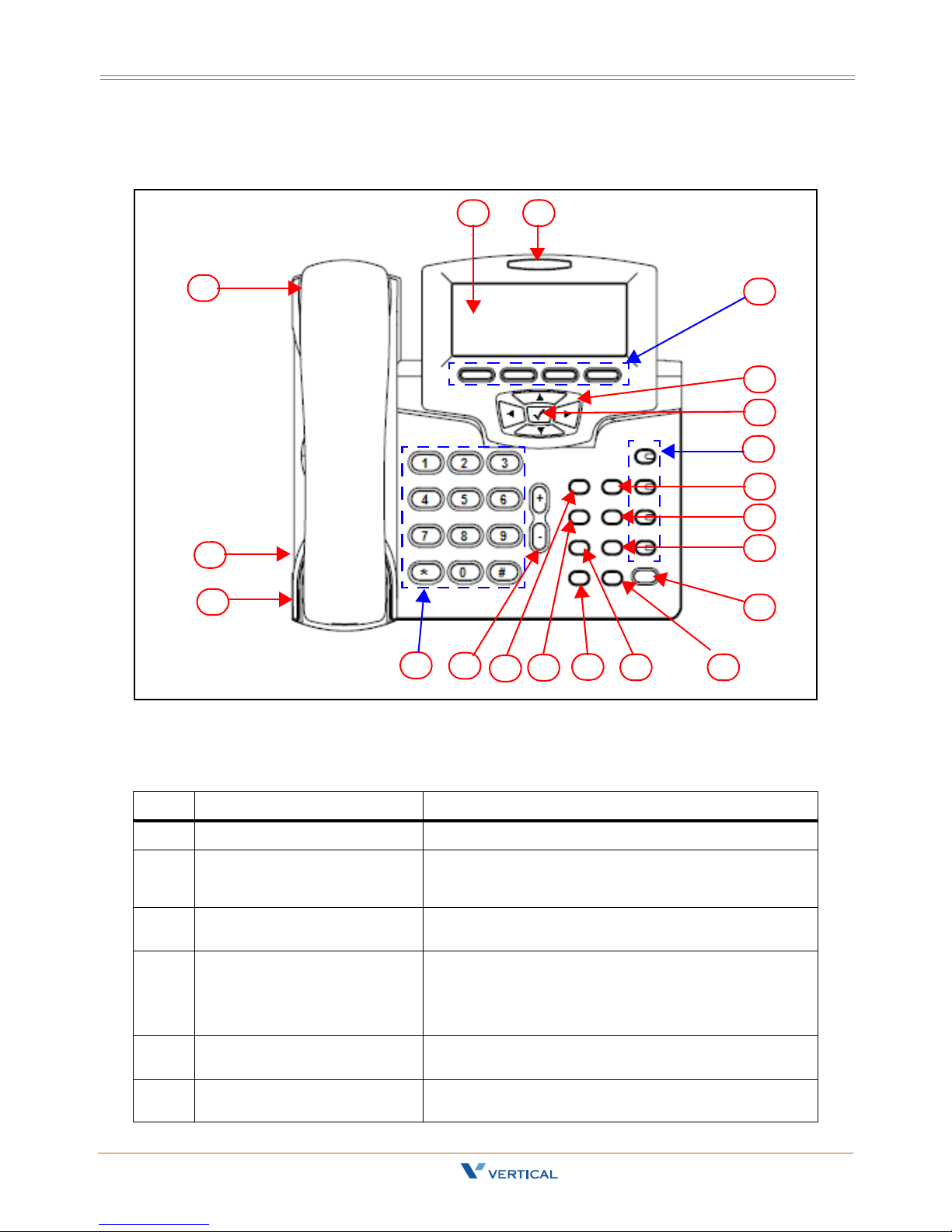
Identifying Buttons and Hardware
32
1
20
19
18
17
16
15
14
4
5
6
7
8
9
10
11
1213
IP Phone Function Keys
No. Part Name Description of Function
1 Handset Phone Handset
2 LCD The LCD shows phone features such as the time,
3 Message LED This LED illuminates red to indicate a message
4 Soft Keys These four keys are used for item selection or control
5 Navigator Control Keys Four arrows on the Navigator Control are used to
6Navigator [
Xcelerator IP User Guide March 2007
4] OK Key This key is normally used to confirm a configuration
date, your phone number, caller ID, line/call status,
and soft key tabs.
waiting status.
on the LCD screen. Each key function depends on its
corresponding content displayed on the LCD at that
time. (Example: Press soft key 1 to enter the
configuration menu).
scroll through items on the LCD screen.
setting or phone number dial.
Page 9

IP2007 Product Description 1-5
Chapter 1 - Introduction
No. Part Name Description of Function
7 Number Keys (1,2,3,4) These four keys can be used for line selection or
programmable features. A green LED is associated
with each key to indicate its line/call status.
8 T r ansfer K ey This key is used to transfer a call to another IP phone.
9 Redial Key This key is used to redial the last dialed number
automatically.
10 Hold Key The Hold key is used to place the current call on hold
and allows you to then answer another new call.
Pressing the key again will release the hold function.
11 Speaker Key This key is used to activate/de-activate the Handsfree
dial or talk. A green LED is associated to indicate its
status.
12 Mute Key This MUTE key is used to activate/de-activate the
voice transmit from this IP phone. A red LED is
associated to indicate its status.
13 Phone Book Key This key is used to enter the Phone Book to place a
call or to edit. The LCD screen will provide Phone
Book prompts once this key is pressed.
14 Headset Key This key is used to activate/de-activate the headset.
A green LED is associated to indicate its status.
15 Conference Key This key is used to drop the current multiple-
connected phones into a conference. It is a phonebridged function.
16 Message Key This key is used to get access to the voice mail
system for message retrieval.
17 Volume Control Key This key is used for volume control:
When the phone is idle, the ringer volume is adjusted.
When talking on an active call, the Handset/Speaker/
Headset output volume is adjusted.
18 Numeric Keypad (0-9,*,#) This is the numeric keypad for dialing numbers.
19 Headset Wire Port RJ-9 jack by the left bottom side of IP phone
20 Headset Cord Port RJ-9 jack by the left bottom side of IP phone
Xcelerator IP User Guide March 2007
Page 10

1-6 IP2007 Product Description
Chapter 1 - Introduction
LED Status Indicators
No. Key/Indicator Color Static OFF Static ON
8 Message
indicator
13 Number keys
14 Speaker key
15 Mute key Red Mute is off. Mute is on. N/A
16 Headset key
Red No new
messages
Green Default Mode Headset:
Green Default;
Handset or
Headset
modes.
Green Default;
Handset
N/A Slow blinking for
During call
Mode Handset:
During call only
if hands-free is
active.
When SPKR is
on for on-hook
dialing or
hands-free
talking.
Headset &
Handset are off.
When Headset
is on for onhook dialing or
hands-free
talking.
Handset &
Speaker are off.
Blinking ON/
OFF
new voice
message
indication
Headset/Handset
Mode: Ringing
cadence on
incoming call;
Group listening in
active cadence
When an
incoming call is
ringing (in
Handset mode)
When an
incoming call is
ringing (in
Headset mode).
[The rings take
place in speaker
and headset]
8, 13,
14, 15,
& 16
Xcelerator IP User Guide March 2007
All LEDs for
system status
Green Ready Boot:
During system
booting
Boot:
When system
booting failure or
fault occurs.
Page 11

IP2007 Product Description 1-7
Chapter 1 - Introduction
IP Phone Rear & Side Views
The following illustrates the rear and side views of the IP phone. Refer to the callout
numbers, and associated simple description of the part in the following table.
No. Part Name Description of Function
1 LCD screen cover The back of the LCD screen
2 Wall-Mount Hole For mounting the phone on the wall
3 Hinge of Stand A leg is installed here to support the IP phone at different
4 Service door The Service Door is only for engineering use. Inside, there
5 Input/Output ports For installation, connect the cables here (refer to the next
6 Hinge of Chassis The small frame is fixed here. You do not need to
7 The back of Cradle This is the back cover of the handset cradle.
8 Product label This shows product production information, including
9 Handset cord port RJ-9 jack on the side of IP phone.
10 Handset wire port RJ-9 jack on the side of IP phone.
angles. For wall-mounting, remove the leg.
is a console port. Users should not open this door.
[Note: To use this port, you need a special converter cable
(RJ-45 to DB-9)]
figure and associated table for the details).
disassemble this frame for wall-mounting.
product model, serial number, and MAC address.
Xcelerator IP User Guide March 2007
Page 12
1-8 IP2007 Product Description
Chapter 1 - Introduction
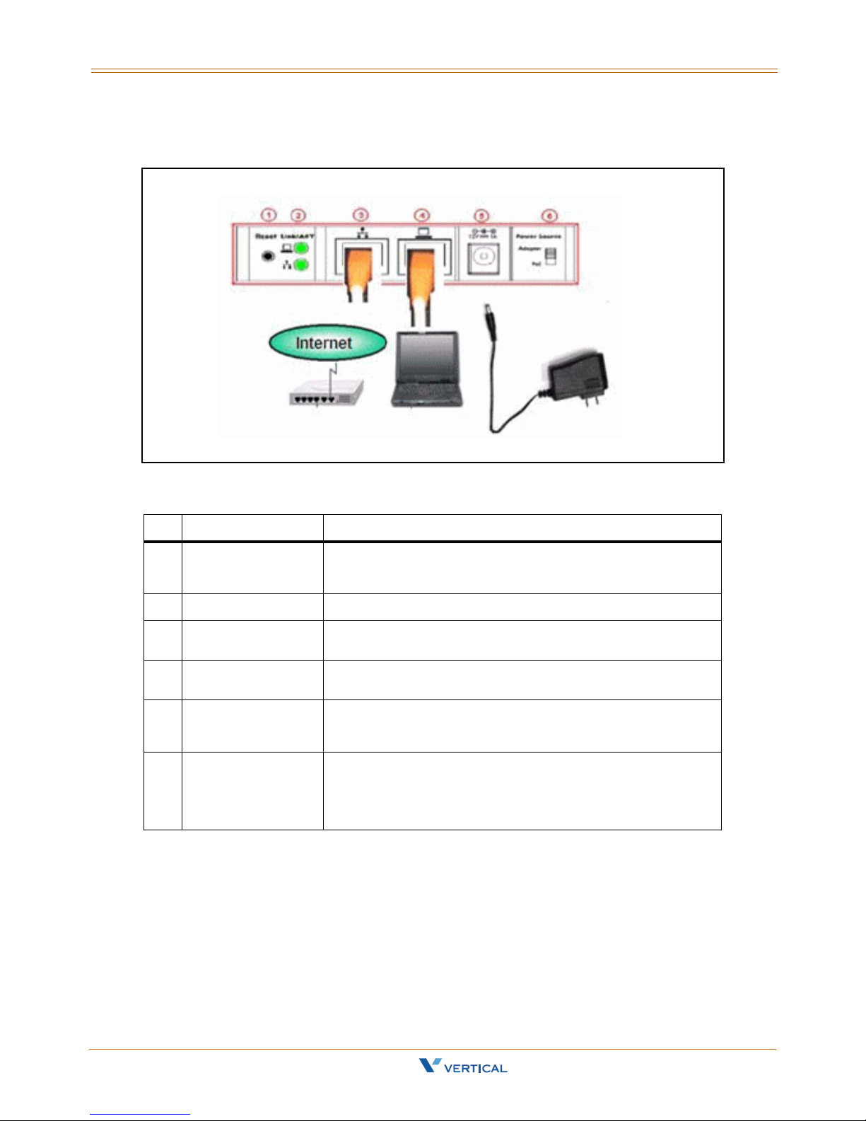
IP Phone In/Out Ports
No. Part Name Description of Function
1 Reset Button The Reset Button is for system engineering use (The
2 Link/Activity LEDs The LEDs indicate the link status of the WAN and LAN ports.
3 WAN Port RJ-45 Jack 100/10Mbps Ethernet port for connecting to IP
4 LAN Port RJ-45 Jack 100/10Mbps Ethernet port for connecting to PC
5 Power Jack If a power source from adaptor is required, use the
6 Power Source There are two available sources for power: from Power
configuration will be reset to factory settings when
pressed).
network
or Notebook
standard power adaptor supplied in the package (12V/
1000mA).
Adaptor or PoE (Power over Ethernet). The default is
Adaptor. Please set to the appropriate option before
installation. Default setting is Power Adaptor.
Only the Ethernet WAN port supports PoE.
Xcelerator IP User Guide March 2007
Page 13

Install & Connect the
2
Phone
Read the Install & Connect the Phone chapter to perform the following functions:
set up the IP2007 Phone, the phone stand, and the power source switch
connect the handset and the cables
mount the IP2007 Phone on the wall
Xcelerator IP User Guide March 2007
Page 14

Page 15
Assembling the IP Phone 2-3
Chapter 2 - Install & Connect the Phone
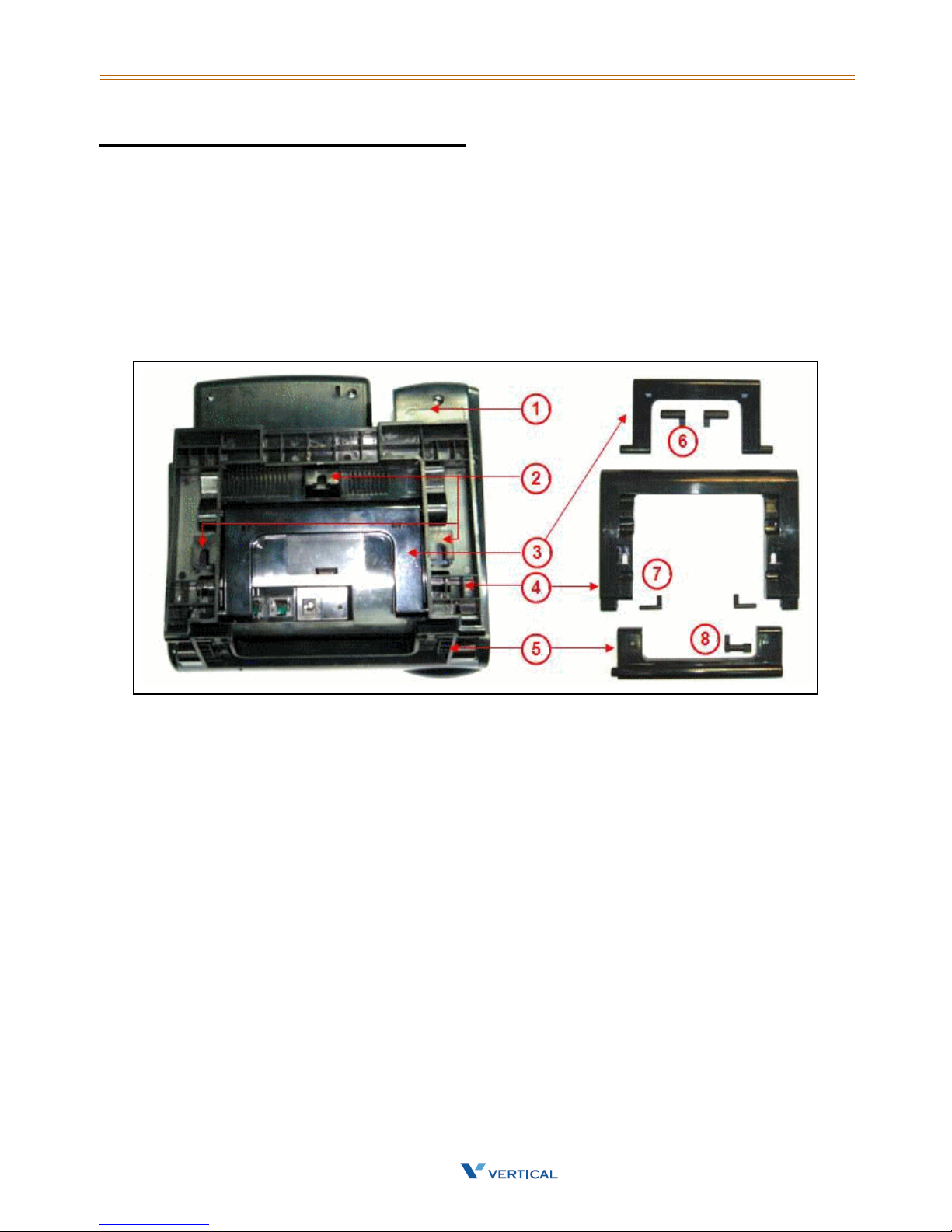
Assembling the IP Phone
After removing the IP phone from the package, you will see the back of IP phone as
shown in the following illustration. The phone (1) is already assembled with three frames.
The U-type leg (3) is used with the big U-type frame (4) that has three step cavities for
three angle positions. Another small U-type frame (5) is fastened to the big U-typ e frame
(4) and the main body of phone (1). You may find these frames are locked together with
different latches (6), (7), and (8) respect iv ely. Do not touch latches (7) and (8). The
latch (6) will be removed if you are do a wall-mount.
Xcelerator IP User Guide March 2007
Page 16

2-4 Assembling the IP Phone
Chapter 2 - Install & Connect the Phone
Setting Up the Stand
Refer to the following steps and the associated illustration to setup the stand of the IP
phone.
Step A Move the big U-type frame (4) downward.
Step B Move the big U-type frame (4) downward to the flat level. The small U-
type frame (5) will get flat concurrently.
Step C Move the U-type leg (3) upward.
Step D Seat the U-type leg (3) onto the big U-type frame (4) at about a 30º
angle position.
-or-
Step E Pull-in the U-type leg (3) and seat it at about a 45º angle position in the
big U-type frame (4).
-or-
Step F Pull-in the U-type leg (3) and seat it at about 60º angle position in the big
U-type frame (4).
Xcelerator IP User Guide March 2007
Page 17
Assembling the IP Phone 2-5
Chapter 2 - Install & Connect the Phone
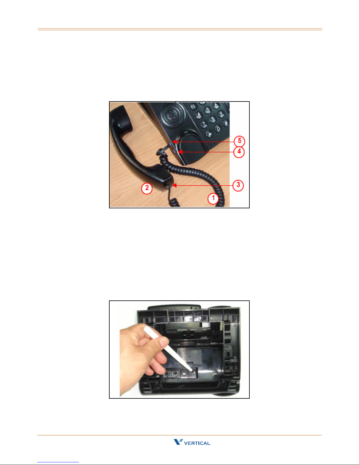
Connecting the Handset
Use the curled cord (1) to connect to the phone jack (3) at the bottom of the handset (2),
as shown in the following illustration. Plug the other end of curled cord to the Handset
jack (5) on the side of IP phone. The other RJ-9 jack (4) is for a headset. This completes
the assembly of the IP phone.
Setting the PoE or PA Power Source Switch
Before connecting the cables, set the power source switch to the correct position. It is
located to the right of the I/O ports on the back, as shown in the following illustration.
Use a pen to set it to one of the following:
Adaptor position - Use this position if you are using an external standard power
adaptor.
PoE position - Use this position if you can offer Power over Ethernet (PoE,
IEEE802.3af compliant) to the phone.
The Power source switch default setting is "Adaptor".
Xcelerator IP User Guide March 2007
Page 18
2-6 Assembling the IP Phone
Chapter 2 - Install & Connect the Phone
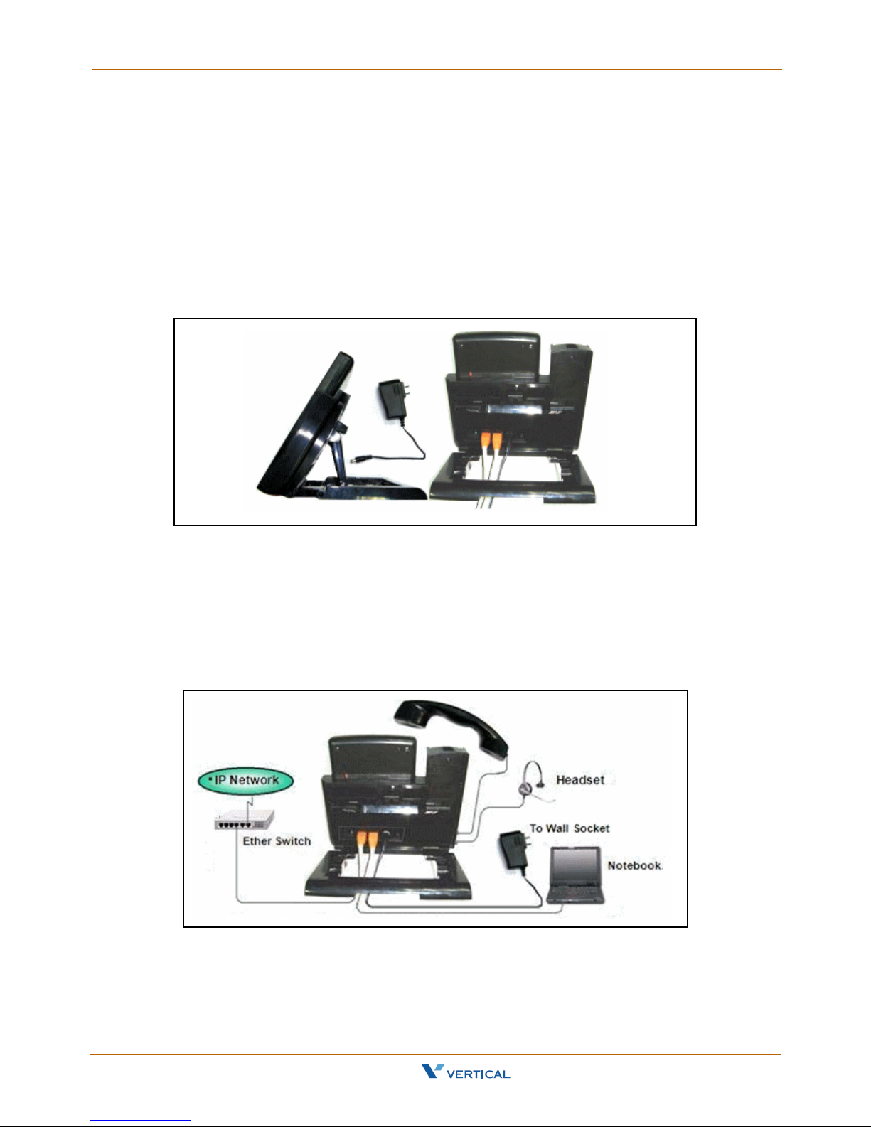
Connecting the Cables
To avoid any problems caused by power-on, the power source will be applied to the
phone last. Do not plug the adaptor head to the wall so cket if you are using Power
adaptor. Do not plug the Ethernet cable to the uplink switch if you are using PoE.
Prepare the Ethernet cable(s), attached in the package, and power adaptor (no need for
PoE user). Plug the cable(s) to their corresponding port s on the back of the IP phone. It is
recommended that you set the stand angle at a 60º angle so that room is sufficient for
easy access to connect the cables. Arrange the cables to go under the big U-type frame
as shown in the illustration.
Full Connection Example
The following illustration is an example of a full connection.
(1) To Handset thru curled cord, (2) to IP Network thru Ethernet cable, (3) to PC/
Notebook thru Ethernet cable, (4) to wall socket thru Power adaptor, and (to use
Headset, plug the headset with R-J9 plug to the Headset jack on the left bottom of the IP
phone) (5) to headset thru headset cable.
Xcelerator IP User Guide March 2007
Page 19

Assembling the IP Phone 2-7
Chapter 2 - Install & Connect the Phone
Mounting the Phone On the Wall
The IP phone can be used on the desktop or mounted on a wall.
Print the screw alignment template (on the next page) and tape it on the wall to
position the 3 screws provided at the right place for the mount-holes on the phone.
Before mounting the IP phone to the wall, detach the handset and curled cord from
the IP phone, then perform the following steps:
Step A On the back of the phone, find the latch (3) on the U-type leg
and remove it.
Step B Remove the other latch (4).
Step C Remove the U-type leg (1). R etain the leg (1) and latches (2) for
possible reuse in a desktop mode.
Step D Seat the big U-type frame onto the back of IP phone.
Step E Re-check that the power source switch is in the correct position.
Connect all cables to the jacks on the phone, then mount the
phone's holes (5 top, 6 left and 7 right) to the screws on the
wall.
Step F Under the hook switch, find and press the cradle latch (8) to let
it down. Then hang up the handset and re-attach the curled
cord.
Xcelerator IP User Guide March 2007
Page 20

2-8 Assembling the IP Phone
Chapter 2 - Install & Connect the Phone
Screw Alignment Template
Resetting the Phone to Factory Defaults
If you want to reset the configuration to the factory default settings, locate the Reset
switch on the back of the phone and complete the following steps:
Step A Remove the power source (adaptor or Ethernet cable) at the remote
end.
Step B Use a pen to press and hold the Reset switch.
Step C To turn on the power again press and hold the Reset switch for over 3
seconds.
Step D Release the Reset switch. The phone will automatically reset the
configuration and the old settings will be gone.
Xcelerator IP User Guide March 2007
Page 21

3
IP2007 Phone Features
Read the IP2007 Phone Features chapter to discover the many features of the IP2007
telephone, and to operate its basic user functions.
Xcelerator IP User Guide March 2007
Page 22

Page 23

Answer a Call 3-3
Chapter 3 - IP2007 Phone Features
Answer a Call
There are various ways to answer an incoming call:
Lift the handset to answer the call.
Press to answer the call in handsfree mode.
Press to answer the call in headset mode.
Auto Answer
You can use the Auto Answer function to automatically answer all incoming calls when
you are busy. You can enable or disable this function through the LCD menus or via the
Web. The default value is disabled.
Phone & Web Access
» Phone Menu = Left soft key to CONFIG > key > arrow to 8. Auto Answer > for
options
» Web Menu = Login > Phone tab > Phone Parameters
Basic Call
To make an intercom call … dial a Station number (IP Terminal, SLT) or a Voice Mail
number.
To make an outgoing call … dial a phone number. The system chooses a PSTN line or IP
trunk via the Call Routing Table to dial out. If it includes * in the phone number, and the
call is dialed through PSTN Trunk, the * will be interpreted as a one second pause.
-orDial a PSTN, an IP Trunk or a Trunk Group number first. After hearing a dial tone, dial the
phone number.
; Enable Auto Answer
Xcelerator IP User Guide March 2007
Page 24

3-4 Call Forward
Chapter 3 - IP2007 Phone Features
Call Forward
You can use Call Forward to redirect your incoming calls from your IP Phone to another
number. You can set three different types of call forward as described in the following
sections.
Always Forward
If you enable Always Forward, all your incoming calls will redirect to another destination.
Busy Forward
If you enable Busy Forward, your incoming calls will redirect to another number when
your phone is connected to a call and you do not wish to receive a second call
simultaneously.
No Answer Forward
If you enable No Answer Forward, your incoming call will redirect to another number after
this call is not answered by you for a specific amount of seconds.
Phone & Web Access
» Phone Menu = Left soft key to CONFIG > key > arrow to 7. Call Forward …
» Web Menu = Login > Personal tab > Call Forward Settings
Call Log
The IP2007 phone can store a call log for your reference. To access your call log, use the
LCD menus. There are three types of Call Logs - Missed Calls, Received Calls, or Dialed
Calls. To dial from a listing, press the soft keys corresponding to the LCD menus display.
Call Waiting
If Call Waiting is enabled for a specific IP2007 station, an alert (muted ring) will be played
on the called party IP2007 when a second call is received and the IP2007 is in use.
To enable Call Waiting … dial *99
If Call Waiting is disabled for a specific IP2007 station, the IP2007 will return a busy tone
to any calling party while the IP2007 is in use.
To disable Call Waiting … dial **99
Xcelerator IP User Guide March 2007
Page 25

Caller Blocking 3-5
Chapter 3 - IP2007 Phone Features
Caller Blocking
You can block up to 10 phone numbers from reaching your phone when a caller attempts
to call you from one of these numbers.
Phone & Web Access
» Phone Menu = Left soft key to CONFIG > key > arrow to 15. Blocking List
» Web Menu = Login + Personal tab + phone number + Save Settings
Caller ID
The Xcelerator-IP, by default, accepts Calling Party Name and Calling Party Number ID.
Calling Party Name is only displayed if the Calling Party Name and Calling Party Number
are entered in the IP2007 Phone Book. The Calling Party Number will be displayed if
delivered from the serving CO.
Phone & Web Access
» Phone Menu = Left soft key to CONFIG > key > arrow to 12. Phone Book
» Web Menu = Login > Phone Book tab > enter a party’s name and number in order for
caller ID to display on incoming calls
Conference
Conference calling allows three parties to simultaneously participate in a call.
To establish a Conference call:
1. Place an internal or external call.
2. Press the HOLD key to place the 1st party on hold.
3. Press the NAV key down arrow to place a second call on this line.
4. Dial the phone number of the 2nd party of this conference.
5. Press to start the conference.
Distinctive Ringing
Distinctive ring cadences can be selected allowing adjacent users to discern which
extension is ringing. It also provides different ring tones for intercom and trunk calls. You
can enable or disable this function through the LCD menus or via the Web.
Phone & Web Access
» Phone Menu = Left soft key to CONFIG > key + arrow to 2. Ring
» Web Menu = Login > Phone tab > Tones Used
Xcelerator IP User Guide March 2007
Page 26

3-6 Do Not Disturb
Chapter 3 - IP2007 Phone Features
Do Not Disturb
You can enable the Do Not Disturb (DND) function, if you do not want any incoming calls
to interrupt your work. All incoming calls will receive a busy tone when they call your
phone number. You can enable or disable this function through the LCD menus or via the
Web.
Phone & Web Access
» Phone Menu = Left soft key to CONFIG > key > arrow to 6. DND
» Web Menu = Login > Phone tab > Phone Parameters
; Enable DND
Drop a Call
There are various ways to drop an existing call:
Place the handset on hook if talking in handset.
Press to drop a handsfree call.
Press to drop a headset call.
Feature Key Programming
Feature Keys can be programmed by phone users. A feature key can be programmed for
line appearance.
To program a Feature Key … dial *70 + (Feature Key number: 1 - 4) + (PSTN, IP Trunk
or Trunk Group number)
Hold/Resume/Navigation in Calls
Only one call can be active at any given time; another call must be placed on hold.
Hold a Call
After you have a connected call, you can use to hold a call.
Resume a Held Call
You can resume a held call by using the soft key under the "Resume" label on the LCD.
The call will return to the connected status.
Navigation in Calls
You can jump between two calls by using . Press the or arrow of the
navigator control key to toggle between the two calls.
Xcelerator IP User Guide March 2007
Page 27

Lines and Calls 3-7
Chapter 3 - IP2007 Phone Features
Lines and Calls
Lines
The term "Line" in this manual represents how many phone numbers are supported on
one phone. A phone can have more than one phone number so that the user can
subscribe to different VOIP service providers.
Calls
The term "Call" in this manual repres ent s how many simultaneous connections can be
made to a single phone number. Each line has two calls capabil ity, so that you can hold
one call and talk to another person in another call.
Mute
To mute the microphone during a call, press the button. The button will illuminate to
indicate that the microphone has been muted.
Press the MUTE button again to re-enable the microphone.
Page Allow/Deny
You can block one-way pages (internal, group, and all page) over the IP phone speaker
by dialing the Page Deny code.
Feature Code Access
To enable Paging … dial *99
To disable Paging … dial **99
Phone Lock/Unlock
The IP2007 Lock feature is used to prevent unauthorized trunk calls from being made
from a specific extension. A locked extension will continue to receive incoming trunk calls,
and a user can continue to place and receive intercom calls; however, outgoing tru nk
calls are blocked. You can access this feature via the Phone or the Web.
Feature Code Access
To lock the phone … dial *97 + (VM password)
To unlock the phone … dial **97 + (VM password)
Phone & Web Access
» Phone Menu = Left soft key to CONFIG > key > arrow to 9. Phone Lock
» Web Menu = Login > Phone tab > Phone Parameters
Xcelerator IP User Guide March 2007
; Phone Lock
Page 28

3-8 Phone Book
Chapter 3 - IP2007 Phone Features
Phone Book
The Xcelerator-IP provides users with a Phone Book, with each entry containing a user
programmed Phone Number and User Name. The phone number can be an extension
number, phone number, or IP address. Up to 400 entries per station user is supported.
Phone & Web Access
» Phone Menu = Left soft key to CONFIG > key > arrow to 12. Phone Book
» Web Menu = Login > Phone Book tab > enter a caller’s name and number for caller ID
to display on incoming calls
Place a Call
There are various ways to place a call:
Lift the handset and dial the number pad as a regular phone.
Press to perform handsfree dialing.
Press to perform headset dialing.
Press to pickup a specific line.
Dial directly , the phone will automatically pickup in handsfree mode and perform
Redial
The Redial feature automatically dials the last number dialed from the phone.
Press to dial the last number automatic a lly. If the phone is on hook, it will pickup in
handsfree mode automatically and perform handsfree dialing.
handsfree dialing.
You can use the pound [#] key or the [OK] key to complete the number. This will speed up the
calling process.
Xcelerator IP User Guide March 2007
Page 29

Register to a Server 3-9
Chapter 3 - IP2007 Phone Features
Register to a Server
The phone should be configured before it can perform some basic functions. Although the
phone can make a peer to peer VOIP call (the user must remember the IP address of the
called party), it is desirable to have a centralized server to provide the directory service.
This server can be a soft-switch, an IP-PBX, or a simple proxy.
The server has two basic functions:
1) The first is to track active phones and their IP address.
2) The second is passing signaling messages between communication parties.
To make your phone reachable in this VOIP network, your phone has to register to the
server so that when someone dials your phone number the server knows where you are
and informs your IP phone that someone is calling.
Phone & Web Access
» Phone Menu = Left soft key to CONFIG > key > arrow to 16. Admin > SIP
» Web Menu = Login + SIP tab (refer to “SIP Page” on page 5-10)
Speakerphone/Headset/Handset
There are 3 major input/output devices on this phone. To switch between these devices,
follow the audio path transitions described below:
Handset to Handsfree -- You are using the handset and want to switch to handsfree
talking. Press and place the handset on hook. NOTE: The voice will not switch to
speakerphone until you place the handset on hook.
Handset to Headset -- You are using the handset and want to switch to the headset.
Press and place the handset on hook. NOTE: The voice will not switch to headset until
you place the handset on hook.
Handsfree to Handset -- You are using handsfree talking and want to switch to the
handset. Lift the handset off hook and the voice will switch to handset immediately.
Handsfree to Headset -- You are using handsfree talking and want to switch to the
headset. Press and the voice will switch to headset immediately.
Headset to Handset -- You are using the headset and want to switch to handset. Lift
the handset off hook and the voice will switch to handset immediately.
Headset to Handsfree -- You are using the headset and want to switch to handsfree
talking. Press and the voice will switch to speakerphone immediately.
Xcelerator IP User Guide March 2007
Page 30

3-10 Speed Dial
Chapter 3 - IP2007 Phone Features
Speed Dial
You can preset 10 speed dial numbers for fast dialing. Use the following steps to use
speed dial:
1. Lift the handset.
2. You will see "SPD" on the LCD menus. Press the soft key corresponding to the LCD
menus display.
3. You will see "SpeedDial:_" on the LCD display. Enter a valid speed dial bin number
(0-9) and the IP phone will dial out with the number that is preset in the IP phone.
Phone & Web Access
» Phone Menu = Left soft key to CONFIG > key > arrow to 13. Speed Dial
» Web Menu = Login > Personal tab > Speed Dial Entry Settings
Transfer
Transfer redirects a connected call. You can use a Blind or Supervised transfer method to
transfer the call to an extension or an outside phone number.
Blind Transfer
While on a call:
1. Press the TRANSFER key to transfer the call.
2. Dial the desired phone number and the call will transfer automatically.
3. Hang up to release the line.
Supervised Transfer
While on a call:
1. Press the HOLD key to hold this call.
2. Press the down arrow of the navigation control key to start a 2nd call on this line.
3. Dial the desired phone number. You will hear a ring back tone.
4. When the called party answers, advise them of the call being transferred.
5. Press the TRANSFER key and hang up. The Supervised Transfer is complete.
Xcelerator IP User Guide March 2007
Page 31

Voice Mail Access 3-11
Chapter 3 - IP2007 Phone Features
Voice Mail Access
Ask your system administrator for the Voice Mail access number in order to access your
voice mailbox. You will find the "MSG number" field blank; enter an appropriate number.
If you have voice mail in your voice mailbox, you will see a voice mail icon on the left
top corner of the LCD. Press the message icon to access your voice mail.
The Total Recording Message Time for one extension depends on how many extensions are
connected to the Xcelerator IP. (See current members in the Phone Extension Table.) The current
Xcelerator IP configuration allows 240 minutes of recording time.
Recording Time Per Extension = (240 minutes) divided by (Total Members)
Volume Adjustment
Use the VOLUME CONTROL button to adjust the volume.
When using the handset … use this button to adjust the handset output volume.
When using handsfree talking … use this button to adjust speaker output.
When using a headset … use this button to adjust the headset output volume.
When the phone is ringing … use this button to adjust the ringing volume.
Xcelerator IP User Guide March 2007
Page 32

Page 33

4
Read the Configuration Via Menus chapter to learn how to navigate in the menus of your
IP2007 telephone.
Configuration Via Menus
Xcelerator IP User Guide March 2007
Page 34

Page 35

Menu 4-3
Chapter 4 - Configuration Via Menus
Menu
Startup
You can use LCD menus to configure most settings of your IP phone.
Press the LEFT soft key to start menu selection process.
Xcelerator IP User Guide March 2007
Page 36

4-4 Menu
Chapter 4 - Configuration Via Menus
Menu Tree
- Menu Selection
- 1. Volume
+ Ring Volume
+ Handset Speaker
+ Handset Mic
+ Handsfree Speaker
+ Handsfree Mic
+ Headset Speaker
+ Headset Mic
+ 2. Ring
+ 3. Tone
+ 4. Time
+ 5. Info
+ 6. DND
- 7. Call Forward
- Always Forward
+ Toggle
+ Forward Number
- On Busy Forward
+ Toggle
+ Forward Number
- No Answer Forward
+ Toggle
+ Forward Number
+ No Answer Time
+ 8. Auto Answer
+ 9. Phone Lock
- 10. Call Record
+ Dialed
+ Missed
+ Received
+ 11. Ping
+ 12. Phone Book
+ 13. Speed Dial
- 14. Network
- Network Type
+ Static IP
+ DHCP
+ PPPoE
+Netmask
+ Default Gateway
- DNS
+ Primary DNS
+ Secondary DNS
+ Third DNS
+ SNTP
+ 15. Blocking List
- 16. Admin
+ Phone Number
- Account
- Admin
+ Name
+ Password
- User
+ Name
+ Password
- NAT
+ NAT Type
- STUN
+ STUN Server IP
+ STUN Port
+ SIP PING
- Port Mapping
+ Extern Router IP
+ Signal Port
+ Extern RTP Port 1
+ Extern RTP Port 2
- SIP
- SIP Server
+ SIP Proxy
+ Outbound Proxy
+ Registrar Server
+ Registrar Outbound
+ Port
- Authentication
+ Authorized ID
+ Authorized Password
+ DTMF
- Codec
+ G.711 u-law
+ G.711 a-law
+ G.723.1
+ G.729
+ Packet Time
+ Caller ID
+ User Name
+ VLAN
- Download
+ TFTP Server
+ Firmware Upgrade
+ Profile Download
+ Reset
+ Boot
+ 17. Quit
The menu tree begins at the top of the left column. After "Blocking List" at
the bottom of that column, the menu tree continues at the top of the right
column.
Xcelerator IP User Guide March 2007
Page 37

Menu 4-5
Chapter 4 - Configuration Via Menus
This is the first display shown when you press the left soft key.
Navigate in the Menu
Use the Navigator Control key to scroll to a desired item.
Press to enter the sub-tree for the selected item.
Press to confirm and save the setting of a specific item. Thereafter, the menu will
roll back to the upper level of the menu tree. You can also press the left arrow of the
Navigator Control key to roll back to the upper level of the menu tree without causing the
system to resave.
Xcelerator IP User Guide March 2007
Page 38

4-6 Menu
Chapter 4 - Configuration Via Menus
Enable or Disable Settings
You can enable or disable certain item settings. Use the up or down arrow to
toggle an item option. Example:
Xcelerator IP User Guide March 2007
Page 39

Menu 4-7
Chapter 4 - Configuration Via Menus
Numeric and Alpha Characters
You can input numeric or alphabetic characters in certain menus, such as in the Phone
Book. When you are on a menu that accepts characters, you will see "ABC" above the left
soft key. Press the left soft key to cycle through the options of ABC, 123, and abc. These
options represent characters in upper case, numeric digits, and characters in lower case.
You can switch between the three options during one entry to use upper and lower case
characters as well as numbers.
To enter alphabetic characters, select ABC or abc with the left soft key, then repeatedly
press the dial pad button that has the character you want until the desired character
appears. The display will cycle through all of the characters associated with the button.
Saving the Configuration
Some changes are saved immediately as you change settings. All settings will be saved
when you leave the Menus. You will see "Saving change … Please wait" on the LCD.
Xcelerator IP User Guide March 2007
Page 40

Page 41

5
Configuration Via Web
Read the Configuration Via Web chapter to learn how to use your IP2007 telephone by
using the web interface.
Xcelerator IP User Guide March 2007
Page 42

Page 43
Web 5-3
Chapter 5 - Configuration Via Web
Web
Access
To access the phone configuration, enter the IP address in the Address field of your web
browser, http://192.168.1.10.
To confirm IP address -- If you are unsure about the IP address, you can verify the
current IP address on your IP phone by pressing the Left soft key to access the CONFIG
menu and using the down arrow to select the 5. Info menu.
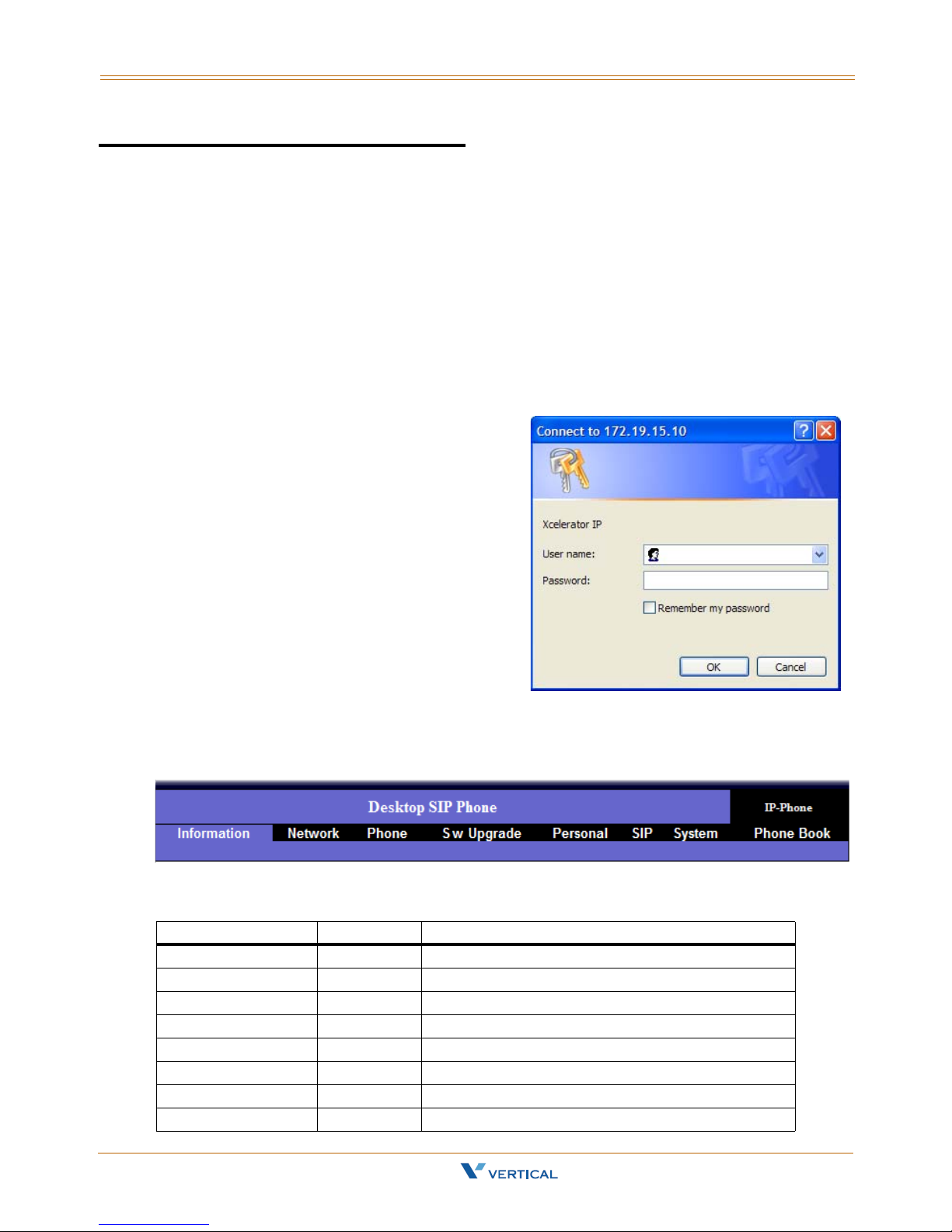
Login
The following dialog box will pop up and
prompt you to provide the user name and
password in order to prevent unauthorized
users from accessing your phone.
The default names and passwords for the
Web are as follows:
User Name = user
User Password = 1111
(Administrator) User Name = admin
(Administrator) Password = 1234
Web Page Menus
When accessing the web pages for the
IP2007 Phone, you can make configuration
changes in each category. Click on a menu to access a specific group of settings.
Information | Network | Phone | SwUpgrade | Personal | SIP | System | Phone Book
Web Page Buttons
Button Web Page Description
Cancel All Discard all changes entered on this page
Download Settings SW Upgrade Download files to upgrade phone firmware
Logout All Exit and close browser window
Next/Previous Phone Book View next or previous page of Phone Book entries
Reboot Information Update phone to capture changes made to s/w
Save Settings All Save changes entered on this page to the IP Phone
Set All to Default System Change ALL parameters to factory default settings
Update SW Upgrade Locate new file provided (s/w, profile, logo, font)
Xcelerator IP User Guide March 2007
Page 44

5-4 Information Page
Chapter 5 - Configuration Via Web
Information Page
The Information Page displays when you log into the phone's web page. This "view only"
page shows general information regarding your IP2007 Phone.
Network Information
IP T ype | Current IP | Subnet Mask | Defaul t Gateway | Primary DNS | Second ary DNS
Product Information
Product Name | Software Version | MAC Address | Hardware Version
Profile Status
Phone Number | Registration State | SIP Proxy Server
Network Settings
The Network Settings page allows you to access the following network categories:
Internet Connection Items | Optional Network Items | QoS Items
Xcelerator IP User Guide March 2007
Page 45

Network Settings 5-5
Chapter 5 - Configuration Via Web
Network Parameters
Internet Connection Items
IP T ype Select how this phone receives IP address - DHCP or Static IP; Default = DHCP
IP Address Static IP address; Default = 0’s
Subnet Mask Static Subnet Mask
Default Gateway Static Default Gateway
Optional Network Items
Primary DNS Static Primary DNS
Secondary DNS Static Secondary DNS
Third DNS Static Third DNS
Time Server Static Time Server
QoS Items
DIFFSERV for RTP Options:
Best Effort
AF Class 1 (DROP: Low/Medium/High)
AF Class 2 (DROP: Low/Medium/High) |
AF Class 3 (DROP: Low/Medium/High)
AF Class 4 (DROP: Low/Medium/High)
Expedited Forwarding
Default = Best Effort
DIFFSERV for Signal Options:
Best Effort
AF Class 1 (DROP: Low/Medium/High)
AF Class 2 (DROP: Low/Medium/High)
AF Class 3 (DROP: Low/Medium/High)
AF Class 4 (DROP: Low/Medium/High)
Expedited Forwarding
Default = Best Effort
VLAN Mode Options: None | Automatic | Static; Default = None
Voice VLAN ID Voice VLAN ID; Default = 2
VLAN Option ID VLAN option ID; Default = 176
Xcelerator IP User Guide March 2007
Page 46

5-6 Phone Settings
Chapter 5 - Configuration Via Web
Phone Settings
The Phone Settings page allows you to access the following phone categories:
Volume Control
Tones Used
Phone Parameters
Prefix Entry Settings
Dial Plan
Xcelerator IP User Guide March 2007
Page 47

Phone Settings 5-7
Chapter 5 - Configuration Via Web
IP Phone Parameters
Volume Control
Handset Mic Set input level of handset microphone: 1-10. Default = 6
Handset Speaker Set output level of handset speaker: 1-10. Default = 6
Speaker Mic Set input level of hand-free microphone: 1-10. Default = 6
Speakerphone Set output level of hand-free speaker: 1-10. Default = 6
Headset Mic Set input level of headset microphone: 1-10. Default = 6
Headset Speaker Set output level of headset speaker: 1-10. Default = 6
Ring Tone Volume Set output level of ring tone: 1-10. Default = 6
Side Tone Set sound level between mouthpiece and earpiece: 1-10. Default = 5
Tones Used
Tone Type Select tone type for your country; Default = U.S.
Ring Type Select ring type for your country; Default = U.S.
DTMF Relay Select way to send DTMF through in-band or out band mechanism:
RFC2833 PayLoad SIP DTMF detection; Default = 101
RFC2833 DTMF Tone Duration Options: 560ms | 640ms | 800ms | 960ms | 1120ms | 1280ms;
Hold Remind Time Call on hold reminder tone (10-120 seconds, increments of 10 secs);
Enable Auto Answer Turn on auto answer function; Default = Disabled
Enable DND Turn on DND function; Default = Disabled
Enable Echo Canceller Remove echo to improve voice quality; Default = Enabled
Enable VAD+CNG Voice Activity Detection + Comfort Noise Generator; Default = Disabled
Enable Phone Lock Lock user’s phone; Default = Disabled
Prefix Entry Type (0-9) Options: Disabled | Add | Replace; Default = Disabled
Prefix Entry Pattern (0-9) Digit to dial out
None | To ne (In-Band) | RFC2833 | SIP-INFO. Default = RFC2833
Default = 800
Phone Parameters
Default = 60
Prefix Entry Settings
Prefix Entry Replace Replaces digit to dial out
Dial Plan Determines how to route calls
Xcelerator IP User Guide March 2007
Page 48

5-8 Software Upgrade
Chapter 5 - Configuration Via Web
Software Upgrade
The Software Upgrade page allows you to access the following s/w upgrade categories:
Server Items
Firmware Files
S/W Upgrade Parameters
Server Items
Server Type TFTP | FTP; Default = TFTP
Server IP Address FTP server address; Default = 192.168.1.100
Files Directory FTP directory where the firmware and profile is located
Server User Name User name of the account on the FTP server; Default = root
User Password Password of the account on the FTP server
Firmware Files
Software app.bin.gz
Profile IP2007.cfg
Logo logo.tcbmp
Font local.font
WEB Logo WebLogo.jpg
Xcelerator IP User Guide March 2007
Page 49

Personal Settings 5-9
Chapter 5 - Configuration Via Web
Personal Settings
The Personal Settings page allows you to access the following call categories:
Call Forward Settings | Caller Blocking Settings | Speed Dial Entry Settings
Personal Parameters
Enable Always Forward &
Forward to user@[host]
Enable On Busy Forward &
Forward to user@[host]
Enable No Answer Forward &
Forward to user@[host]
No Answer Timeout (sec) Sets the timeout for the No Answer Forward function. Default=20
Enable Block Anonymous call Default = disabled (unchecked)
Caller Blocking Entry (0-9) 10 caller blocking settings. You can set up 10 numbers to prevent
Speed Dial Entry (0-9) 22 speed dial entries 1-22 (equals speed bins 0-21)
Xcelerator IP User Guide March 2007
Call Forward Settings
Turns on unconditional forward, all calls will automatically forward to
the number entered; Default = disabled (unchecked)
Turns on the On Busy Forward function. When extension is busy, calls
will forward to the number entered; Default = disabled (unchecked)
Turns on the No Answer Forward function; Default = enabled
(checked) - sends calls to Voice Mail
Caller Blocking Settings
them from ring you if a caller calls you from one of these numbers.
Speed Dial Entry Settings
Page 50

5-10 SIP Page
Chapter 5 - Configuration Via Web
SIP Page
ADMIN Function -- In order to access the SIP parameters, you must log in as a System
Administrator. (Logging in as a station user will prevent this page from loading.)
The SIP page allows an administrator to set up the following SIP parameters:
SIP Proxy Server
SIP Registrar Server
Subscriber Information
Optional SIP Header
RTP Parameters
Voice Mail Items
Codec Settings
Xcelerator IP User Guide March 2007
Page 51

SIP Page 5-11
Chapter 5 - Configuration Via Web
SIP Parameters
SIP Proxy Server
SIP Proxy Server SIP proxy server address
Outbound Proxy Server Outbound proxy server address
Server Port Proxy server port; Default = 5060
SIP Secondary Proxy Server Redundant proxy server
SIP Surviving Proxy Server Creates a SIP proxy loop to find available SIP proxy server
SIP Registrar Server
Registrar Server Registrar server address
Registrar Outbound Server Registrar outbound server address
Registrar Server Port Registrar server port; Default = 5060
Registrar Expire Time (sec) Expiration time for REGISTER request; Default = 180
Subscriber Information
User Name User name to appear in phone LCD display
Phone Number Phone number assigned to phone
Authorized ID Authentication user name
Authorized Password Authentication password
Enable Caller ID Enables sending Display Name
Display Name Name to appear in phone LCD display to remote users
Locating SIP Server Default = disabled (unchecked)
SIP Domain Use SIP Domain name instead of IP address
End dial on # Allows entering # sign for speed dialing after dialing number
Dial Timeout (sec) Default = 2
Optional SIP Header
Optional Header 1 Optional SIP header in message
Optional Header 2 Optional SIP header in message
RTP Parameters
RTP Port 1 RTP Port for channel 1; Default = 10002
RTP Port 2 RTP Port for channel 2; Default = 10004
Enable Statistic Default = disabled (unchecked)
Statistic Server Default = 10004
Statistic Port Default = 10000
Xcelerator IP User Guide March 2007
Page 52

5-12 SIP Page
Chapter 5 - Configuration Via Web
Voice Mail Items
Subscribe MWI Subscribe to voice mail server
Voice Mail Server Voice mail server address
MSG Number Default = voicemail
Codec Settings
Codec G.711u-law Set G.711u-law protocol preference: None | First | Second | Third |
Fourth; Default = First
G.711u Packet Time Options: 10-80(ms) Default = 30(ms)
Codec G.711a-law Set G.711a-law protocol preference: None | First | Second | Third |
Fourth; Default = Second
G.711a Packet Time Options: 10-80(ms) Default = 30(ms)
Codec G.729 Set G.729 protocol preference: None | First | Second | Third |
Fourth; Default = Fourth
G.729 Packet Time Options: 10-80(ms) Default = 30(ms)
Codec G.723.1 Set G.723.1 protocol preference: None | First | Second | Third |
Fourth; Default = Third
G.723 Packet Time Options: 10-80(ms) Default = 30(ms)
G.723.1 Bit Rate Set the bit rate for G.723.1 protocol: 5.3kb/s | 6.3kb/s
Default = 5.3kb/s.
NAT Items
NAT Type Options: None | STUN | SIP PING | Port Mapping | UDP Heartbeat
Default = None
SIP PING Interval Time (ms) SIP PING frequency; Default = 6
STUN Server IP STUN server IP address
STUN Server Port STUN server port; Default = 3478
Extern Router IP External router address for port mapping
Extern Signal Port External SIP signaling port for port mapping; Default = 5060
Extern RTP Port 1 External RTP port for port mapping; Default = 10002
Extern RTP Port 2 External RTP port for port mapping; Default = 10004
Xcelerator IP User Guide March 2007
Page 53

System Settings 5-13
Chapter 5 - Configuration Via Web
System Settings
The System Settings page allows you to access the following system categories:
Administer Settings
Time Settings
Xcelerator IP Feature Items
Feature Key Settings
Xcelerator IP User Guide March 2007
Page 54

5-14 System Settings
Chapter 5 - Configuration Via Web
System Parameters
Administer Settings
Administrator Name The name of the administrator; Default = admin
Administrator Password The password for the administrator; Default = 1234
User Name The name of the station user; Default = user
User Password The password for the user; Default = 1111
User System Log Server Default = disabled (unchecked)
Log level Options: Emergency | Alert | Critical | Error | Warning | Notice |
System Log Address The IP address of the System Server
System Log Port System Log port number (standard)
System Language System Language supported is English; Default = English
Auto DST Automatic daylight saving time flag
Daylight save time Options: -1 | 0 | +1; Default = 0
Starts on Options: Month | Day | Time; Defaults = JAN | 1 | 00:30
Ends on Options: Month | Day | Time; Defaults = JAN | 1 | 00:30
Time Format TIME_24_HOUR | TIME_12_HOUR Default = TIME_24_HOUR
Time Zone Default = GMT+12:00 (Auckland, Wellington, …)
Informational | Debug; Default = Emergency
Time Settings Items
(respectively)
(respectively)
Xcelerator IP Feature Items
Xcelerator IP flag Using Xcelerator IP gateway flag; Default = enabled (checked)
Xcelerator IP Key 1 Type (1-4) Options: None | Line | Feature Key; Default = Line
Feature Key 1 String (1-4) Options: 700 | 701 | 702 | 710 (respectively)
Key Input This field is for Engineering input only (do not use)
Xcelerator IP User Guide March 2007
Feature Key Settings
Page 55
Phone Book 5-15
Chapter 5 - Configuration Via Web
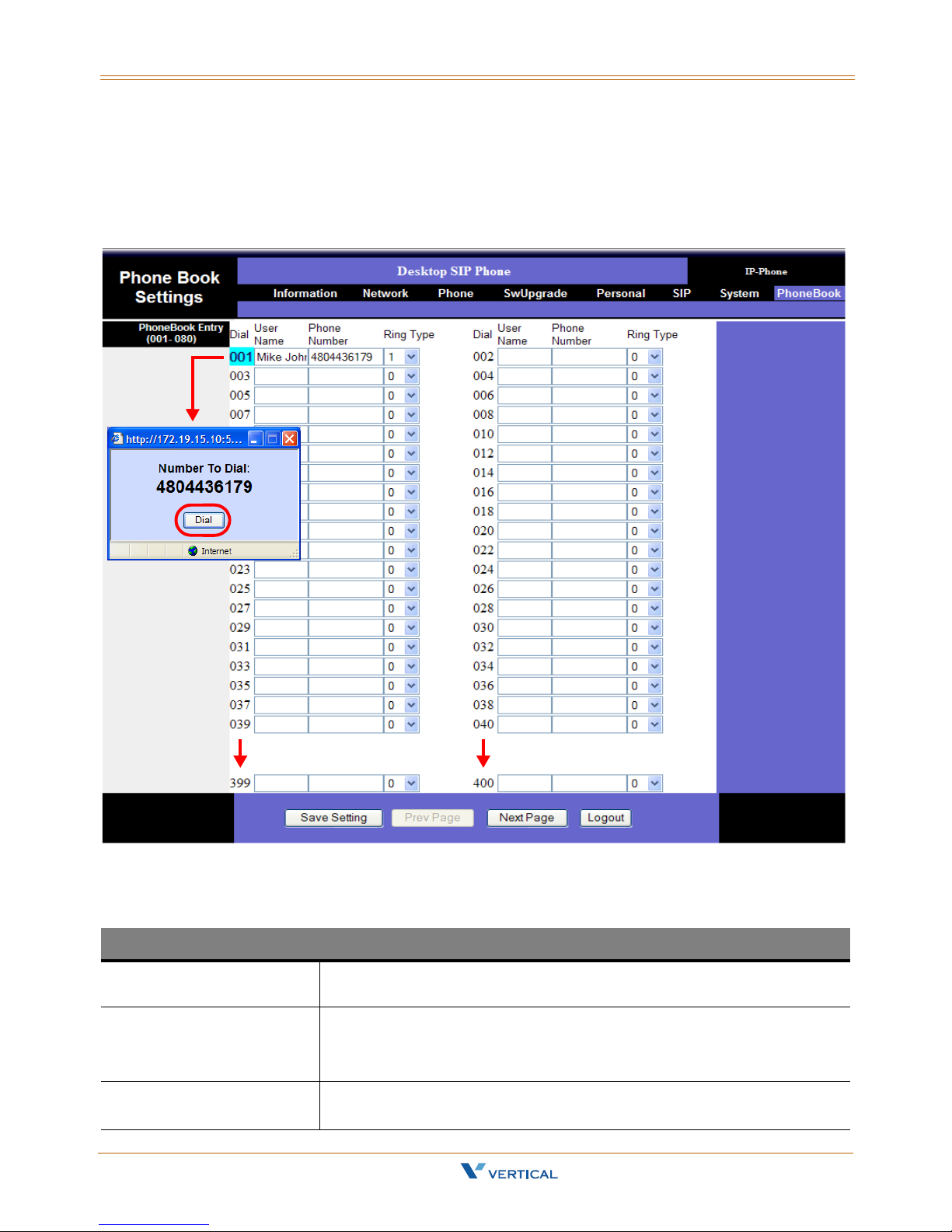
Phone Book
The Xcelerator IP allows each user to store up to 400 name/phone number entries in their
individual Phone Book. Once completed, you will be able to place a call to the desired
person by clicking the Phone Book entry number next to the person’s name/number.
Phone Book Parameters
User Name The user name entered is used to identify the entry while in the Phone
Phone Number The number entered is used to place a call to the person associated with
Ring Type You can assign a unique ring type (1-10) to help distinguish between
Xcelerator IP User Guide March 2007
Phone Book Entry (001-400)
Book. Name is used for caller ID when available.
that phone number.
NOTE -- Enter number only (no dashes or spaces).
types of callers (ex: Executives, Sales Dept., family members, etc.).
Page 56

Page 57

6
Read the Software Upgrade chapter to learn how to update your IP 2007 telephone with
the latest software configuration.
Software Upgrade
Xcelerator IP User Guide March 2007
Page 58

Page 59
Required Components 6-3
Chapter 6 - Software Upgrade
Required Components
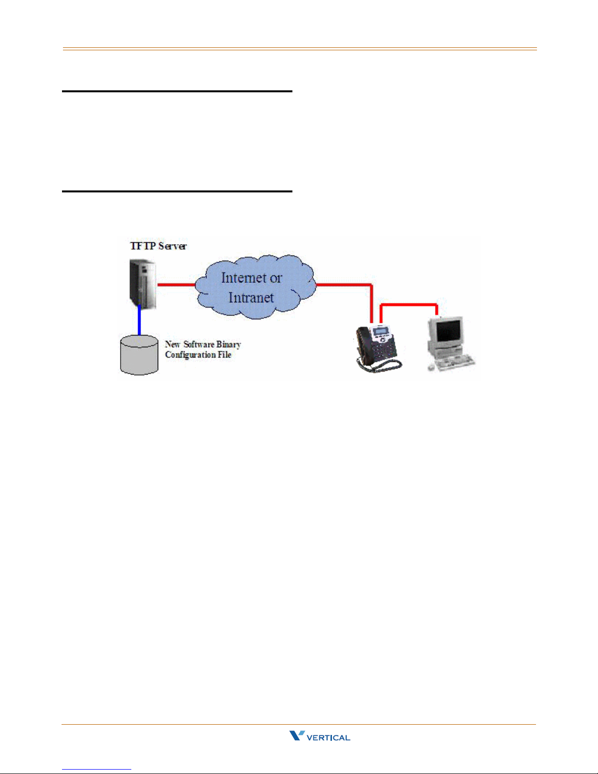
A working IP network that is established and configured for IP phone.
A TFTP server that is configured on your network (example: TFTP32 server)
Latest software image or configuration file.
Environment Setup
Prepare TFTP Server
Make sure the TFTP server has been properly installed in the server.
Put the software file in the TFTP root directory.
Configure Phone for TFTP Access
Configure the correct TFTP server address.
Configure the file name to be downloaded.
Xcelerator IP User Guide March 2007
Page 60

6-4 Software Upgrade Procedure
Chapter 6 - Software Upgrade
Software Upgrade Procedure
To upgrade the phone software via the Web:
1. On the Server computer, create a TFTP or FTP folder on the c: drive "root" directory.
2. Make sure the same Server IP address appears in both areas:
IP2007 SIP Phone web page
-andTFTP/FTP software program
3. Copy the updated file provided into the newly created TFTP/FTP directory.
4. If necessary, change the name of the software file on the web or in the TFTP/FTP
program, so that the filename matches in both places.
2
4
2
3
4
5. Click the "Save Settings" button to capture the new settings.
During the upgrade process, the phone LCD will display the following messages:
"Erasing Flash", "Writing Flash", and "Write Complete".
When the software download is complete, the phone will automatically reboot.
6. To verify a successful download, you can use the web interface or the IP2007 phone:
via Web -- click on the "Information" tab to view th e Software Version, OR
via Phone -- press the Left soft key, go to "5. Info" and scroll to "Firmware Version".
Xcelerator IP User Guide March 2007
Page 61

Software Upgrade Procedure 6-5
Chapter 6 - Software Upgrade
Upgrade Troubleshooting
If the phone download image fails, it can be caused by any of the following reasons:
The TFTP server is not working. (You can Ping the server from your computer. You
can also login to the server from your computer to verify this.)
The account information is incorrect (Incorrect user name or password).
The TFTP server address is incorrect.
The network configuration of the phone is incorrect (You can issue a Ping from IP
Phone to verify this).
The file is not located where you expected it to be. You can use your TFTP client
login to the TFTP server (using the same account) to verify this.
The file is in position, but the folder setting on the phone is incorrect.
The file is in position and the folder is correct, but the filename is incorrect.
TFTP Software - Free Download
If you do not already have an TFTP program, you can go to the link provided and
download an application for free … http://www.solarwinds.net/downloads
Vertical Communications does not provide support for this TFTP product.
For technical assistance, contact Solar Winds.
Xcelerator IP User Guide March 2007
Page 62

Page 63

Index i
Index
A
Always Forward [3-4]
Answer a Call
Auto Answer
[3-3]
[3-3]
B
Basic Call [3-3]
Busy Forward
Buttons and Hardware, identifying
[3-4]
C
Cables, connecting [2-6]
Call Forward
Always Forward
Busy Forward
No Answer Forward
Call Log
Call Waiting
Caller ID
Calls - Placing
Conference
Configuration Via Web
Access
Information Page
Login
Personal Settings
SIP Page
Software Upgrade
System Settings
[3-4]
[3-4]
[3-4]
[3-4]
[3-4]
[3-4]
[3-5]
[3-8]
[3-5]
[5-3]
[5-4]
[5-3]
[5-9]
[5-10]
[5-8]
[5-13]
D
Distinctive Ringing [3-5]
Do Not Disturb
Drop a Call
[3-6]
[3-6]
[1-4]
Hold a Call
Hold/Resume/Navigation in Calls
[3-6]
I
IP Phone
assembling
Function Keys
In/Out Ports
Rear & Side Views
setting up the stand
wall mounting
[2-3]
[1-4]
[1-8]
[1-7]
[2-4]
[2-7]
L
LED Status Indicators [1-6]
Lines and Calls
[3-7]
M
Menu Tree [4-4]
Menu, navigating
Mute
[3-7]
[4-5]
N
Navigation in Calls [3-6]
No Answer Forward
Numeric and Alpha Characters
[3-4]
[4-7]
P
Package Contents [1-3]
Page Allow/Deny
Phone Book
Phone Lock/Unlock
Place a Call
PoE or PA Power Source Switch
Product Description
[3-7]
[3-8]
[3-7]
[3-8]
[1-3]
[3-6]
[2-5]
E
Enable or Disable Settings [4-6]
F
Factory Default Settings, resetting [2-8]
Feature Key Programming
Full Connection, example
[3-6]
[2-6]
H
Handset,connecting [2-5]
Xcelerator IP User Guide March 2007
R
Redial [3-8]
Register to a Server
Resume a Held Call
[3-9]
[3-6]
Page 64

ii Index
S
Saving the Configuration [4-7]
Screw Alignment Template
Software Upgrade
Configuring Phone for TFTP Access
Environment Setup
Prepare TFTP server
Procedure
Required Components
Speakerphone/Headset/Handset
Speed Dial
[6-4]
[3-10]
[2-8]
[6-3]
[6-3]
[6-3]
[6-3]
[3-9]
T
Transfer [3-10]
Blind Transfer
Supervised Transfer
[3-10]
[3-10]
V
Voice Mail Access [3-11]
Volume Adjustment
[3-11]
Xcelerator IP User Guide March 2007
 Loading...