

Page 1

Release 1.0 - Build 7 10.0.20070817.0.0 (0823)
For Review Only - Draft Document 09/07/07
COMPANY CONFIDENTIAL - DO NOT Distribute
9CXG+2
+PUVCNNCVKQP)WKFG
Last Updated 9/07/07
Page 2

Wave IP 2500 Installation Guide
For Review Only - Draft Document 09/07/07
COMPANY CONFIDENTIAL - DO NOT Distribute
Vertical Communications, Inc. reserves the right to revise this publication and to make changes
in content without notice.
© 2007 by Vertical Communications, Inc. All rights reserved.
This publication contains proprietary and confidential information of Vertical C ommunications,
Inc. The contents of this document may not be disclosed, copied or translated by third parties,
in any form, or by any means known, or not now known or conceived, without prior explicit
written permission from Vertical Communications, Inc.
LIMIT OF LIABILITY/DISCLAIMER OF WARRANTY
Vertical Communications, Inc. makes no representation or warranties with respect to the
accuracy or completeness of the content of this publication and specifically disclaims any
implied warranty of merchantability or fitness for any particular purpose, and shall not be liable
for any loss of profit or any other commercial damage, including but not limited to, special,
incidental, or consequential.
TRADEMARKS
Vertical Communications and the Vertical Communications logo and combinations thereof,
DiscoveryCT, Infinite, Nomad IP, PathFinder IP, XTS IP, XTSc, Telenium IP, Triad, and
Xcelerator IP are trademarks and Artisoft, Comdial, InstantOffice, StarPlus, TeleVantage,
Vertical Networks and Vodavi are registered trademarks of Vertical Communications, Inc. All
other brand and product names that ap pear in this publication are used for identif ication only
and are the property of their respective holders.
ii
Page 3

%QPVGPVU
For Review Only - Draft Document 09/07/07
COMPANY CONFIDENTIAL - DO NOT Distribute
%JCRVGT #DQWV6JKU)WKFG
Getting the most out of this guide - - - - - - - - - - - - - - - - - - - - - 1-1
Using the Help system - - - - - - - - - - - - - - - - - - - - - - - - - - - - 1-3
Conventions used in this guide - - - - - - - - - - - - - - - - - - - - - - 1-3
Special messages - - - - - - - - - - - - - - - - - - - - - - - - - - - - - - - - - - - - - - - 1-3
Terms used - - - - - - - - - - - - - - - - - - - - - - - - - - - - - - - - - - - - - - - - - - - 1-3
Type conventions - - - - - - - - - - - - - - - - - - - - - - - - - - - - - - - - - - - - - - 1-4
Related reading - - - - - - - - - - - - - - - - - - - - - - - - - - - - - - - - - 1-5
Manuals - - - - - - - - - - - - - - - - - - - - - - - - - - - - - - - - - - - - - - - - - - - - - 1-5
Quick Reference Guides - - - - - - - - - - - - - - - - - - - - - - - - - - - - - - - - - - 1-5
%JCRVGT $GHQTG;QW$GIKP
Support services - - - - - - - - - - - - - - - - - - - - - - - - - - - - - - - - 1-6
Corporate Web site - - - - - - - - - - - - - - - - - - - - - - - - - - - - - - 1-6
System security - - - - - - - - - - - - - - - - - - - - - - - - - - - - - - - - - 1-6
Compliance statements - - - - - - - - - - - - - - - - - - - - - - - - - - - - 1-7
Federal Communication Commission (FCC) statement - - - - - - - - - - - - - 1-7
Underwriter’s Laboratory - - - - - - - - - - - - - - - - - - - - - - - - - - - - - - - - - 1-9
Industry Canada - - - - - - - - - - - - - - - - - - - - - - - - - - - - - - - - - - - - - - - 1-9
Site Preparation - - - - - - - - - - - - - - - - - - - - - - - - - - - - - - - - - 2-1
KKK
Page 4

Wave IP 2500 Installation Guide
For Review Only - Draft Document 09/07/07
COMPANY CONFIDENTIAL - DO NOT Distribute
Safety Requirements - - - - - - - - - - - - - - - - - - - - - - - - - - - - - - 2-3
Unpacking the Wave IP 2500 - - - - - - - - - - - - - - - - - - - - - - - - 2-4
%JCRVGT 5GVVKPI7RVJG8GTVKECN9CXG+2
About the Wave IP 2500 - - - - - - - - - - - - - - - - - - - - - - - - - - - 3-1
Mounting the Wave IP 2500 - - - - - - - - - - - - - - - - - - - - - - - - - 3-4
Environmental Requirements - - - - - - - - - - - - - - - - - - - - - - - - - - - - - - - 2-2
Required Tools - - - - - - - - - - - - - - - - - - - - - - - - - - - - - - - - - - - - - - - - 2-2
Protective Grounding - - - - - - - - - - - - - - - - - - - - - - - - - - - - - - - - - - - - 2-3
Electrical Safety - - - - - - - - - - - - - - - - - - - - - - - - - - - - - - - - - - - - - - - 2-3
Proper Lifting - - - - - - - - - - - - - - - - - - - - - - - - - - - - - - - - - - - - - - - - - 2-4
The Wave IP 2500 base unit - - - - - - - - - - - - - - - - - - - - - - - - - - - - - - - 3-2
Expansion options - - - - - - - - - - - - - - - - - - - - - - - - - - - - - - - - - - - - - - 3-3
Rack mounting the Wave IP 2500 - - - - - - - - - - - - - - - - - - - - - - - - - - - 3-4
Wall mounting the Wave IP 2500 - - - - - - - - - - - - - - - - - - - - - - - - - - - - 3-5
Table mounting the Wave IP 2500 - - - - - - - - - - - - - - - - - - - - - - - - - - - 3-8
Grounding the Wave IP 2500 - - - - - - - - - - - - - - - - - - - - - - - - 3-8
Connecting the Wave IP 2500 to your LAN - - - - - - - - - - - - - - 3-9
Connecting the Wave IP 2500 to power and powering on - - - - 3-10
Connecting to trunk and station ports on the ISC1 - - - - - - - - - 3-11
Installing expansion components - - - - - - - - - - - - - - - - - - - - - 3-12
KX
About the Ethernet ports on the Wave IP 2500 - - - - - - - - - - - - - - - - - - - 3-9
Power failover support - - - - - - - - - - - - - - - - - - - - - - - - - - - - - - - - - - 3-12
Installing EXUs on a Wave IP 2500 - - - - - - - - - - - - - - - - - - - - - - - - - 3-12
Installing a Media Resource Module - - - - - - - - - - - - - - - - - - - - - - - - - 3-14
Page 5

Installing expansion modules and cards - - - - - - - - - - - - - - - - - - - - - - - 3-15
For Review Only - Draft Document 09/07/07
COMPANY CONFIDENTIAL - DO NOT Distribute
Connecting modules and cards - - - - - - - - - - - - - - - - - - - - - - 3-16
Connecting the analog trunk module - - - - - - - - - - - - - - - - - - - - - - - - - 3-17
Connecting the analog universal module - - - - - - - - - - - - - - - - - - - - - - 3-18
Connecting the digital station module - - - - - - - - - - - - - - - - - - - - - - - - 3-18
Connecting the T1 module with drop-and-insert V.35 serial interface - - 3-19
Connecting the analog station card - - - - - - - - - - - - - - - - - - - - - - - - - - 3-19
Connecting the digital station card - - - - - - - - - - - - - - - - - - - - - - - - - - 3-20
Connecting a music-on-hold (MOH) system - - - - - - - - - - - - 3-20
Connecting a paging system - - - - - - - - - - - - - - - - - - - - - - - 3-21
%JCRVGT +PKVKCN%QPHKIWTCVKQP
Obtaining all required HotFixes - - - - - - - - - - - - - - - - - - - - - - 4-2
Wave IP 2500 Installation Guide
Configuring the administrator PC - - - - - - - - - - - - - - - - - - - - - 4-2
Administrator PC requirements - - - - - - - - - - - - - - - - - - - - - - - - - - - - - 4-2
Configuring TCP/IP on the administrator PC - - - - - - - - - - - - - - - - - - - - 4-2
Connecting to the Vertical Wave IP 2500 - - - - - - - - - - - - - - - 4-4
Connecting to the Wave IP 2500 via your network - - - - - - - - - - - - - - - - 4-4
Connecting to the Wave IP 2500 via a modem - - - - - - - - - - - - - - - - - - - 4-7
Applying all required HotFixes - - - - - - - - - - - - - - - - - - - - - - 4-9
Issues that can prevent or affect an upgrade - - - - - - - - - - - - - - - - - - - - 4-10
Adding the Wave IP 2500 to your LAN - - - - - - - - - - - - - - - 4-11
Adding and configuring the Wave IP 2500 on your LAN - - - - - - - - - - - 4-12
Power-cycling the Wave IP 2500 - - - - - - - - - - - - - - - - - - - - 4-15
Resetting the Wave IP 2500 IP addresses to the factory defaults 4-16
X
Page 6

Wave IP 2500 Installation Guide
For Review Only - Draft Document 09/07/07
COMPANY CONFIDENTIAL - DO NOT Distribute
Using the Service Account Utility - - - - - - - - - - - - - - - - - - - - 4-17
%JCRVGT 'PVGTKPICPF#EVKXCVKPI9CXG.KEGPUGU
About Wave licenses - - - - - - - - - - - - - - - - - - - - - - - - - - - - - - 5-2
Entering Wave licenses - - - - - - - - - - - - - - - - - - - - - - - - - - - - 5-4
Activating Wave licenses - - - - - - - - - - - - - - - - - - - - - - - - - - - 5-6
Full vs. trial licenses - - - - - - - - - - - - - - - - - - - - - - - - - - - - - - - - - - - - - 5-2
Obtaining Wave licenses - - - - - - - - - - - - - - - - - - - - - - - - - - - - - - - - - - 5-2
Wave license requirements - - - - - - - - - - - - - - - - - - - - - - - - - - - - - - - - 5-3
Entering Wave licenses by importing a license file - - - - - - - - - - - - - - - - 5-4
Entering Wave licenses by entering license keys manually - - - - - - - - - - - 5-5
Before your licenses are activated - - - - - - - - - - - - - - - - - - - - - - - - - - - 5-6
The activation process - - - - - - - - - - - - - - - - - - - - - - - - - - - - - - - - - - - 5-8
Activating your Wave licenses using one-click activation - - - - - - - - - - - 5-8
Viewing the status of licenses on your system - - - - - - - - - - - - 5-10
%JCRVGT +PUVCNNKPI9CXG9QTMUVCVKQP#RRNKECVKQPU
Introduction - - - - - - - - - - - - - - - - - - - - - - - - - - - - - - - - - - - - 6-1
Requirements - - - - - - - - - - - - - - - - - - - - - - - - - - - - - - - - - - - 6-1
Installing the Wave workstation applications - - - - - - - - - - - - - - 6-4
Using the Wave Workstation Setup - - - - - - - - - - - - - - - - - - - - 6-5
Configuring the Wave workstation applications - - - - - - - - - - - - 6-7
XK
ViewPoint PC requirements - - - - - - - - - - - - - - - - - - - - - - - - - - - - - - - 6-2
TAPI SP and Contact Manager Assistant PC requirements - - - - - - - - - - - 6-3
Terminal server support - - - - - - - - - - - - - - - - - - - - - - - - - - - - - - - - - - 6-4
Page 7

Wave IP 2500 Installation Guide
For Review Only - Draft Document 09/07/07
COMPANY CONFIDENTIAL - DO NOT Distribute
Configuring ViewPoint - - - - - - - - - - - - - - - - - - - - - - - - - - - - - - - - - - 6-7
Configuring the TAPI Service Provider - - - - - - - - - - - - - - - - - - - - - - - - 6-8
Configuring the Wave Contact Manager Assistant - - - - - - - - - - - - - - - - 6-9
Synchronizing system clocks - - - - - - - - - - - - - - - - - - - - - - - - 6-9
#RRGPFKZ% 7UKPI9CXG9QTMUVCVKQP#RRNKECVKQPUYKVJ/KETQUQHV
6GTOKPCN5GTXKEGUQT%KVTKZ/GVC(TCOG
Installing Wave workstation applications on an application server - -
C-1
Installing workstation applications on a Windows 2003 server - - - - - - - C-2
#RRGPFKZ# 6TWPMCPF5VCVKQP2QTVUCPF2KPQWVU
Integrated Services Card (ISC1) - - - - - - - - - - - - - - - - - - - - - - A-1
RJ-21X interface port descriptions and pinouts - - - - - - - - - - - - - - - - - - A-1
Analog Universal Module port descriptions and pinouts - - - - - A-2
RJ-21X interface port descriptions and pinouts - - - - - - - - - - - - - - - - - - A-2
Analog Trunk Module port descriptions and pinouts - - - - - - - - A-3
RJ-21X interface port descriptions and pinouts - - - - - - - - - - - - - - - - - - A-3
Analog Station Card port descriptions and pinouts - - - - - - - - - A-3
RJ-21X interface port descriptions and pinouts - - - - - - - - - - - - - - - - - - A-3
Digital Station Card port descriptions and pinouts - - - - - - - - - - A-5
RJ-21X interface port descriptions and pinouts - - - - - - - - - - - - - - - - - - A-5
Digital Station Module port descriptions and pinouts - - - - - - - A-6
RJ-21X interface port descriptions and pinouts - - - - - - - - - - - - - - - - - - A-6
XKK
Page 8

Wave IP 2500 Installation Guide
For Review Only - Draft Document 09/07/07
COMPANY CONFIDENTIAL - DO NOT Distribute
#RRGPFKZ$ 9CXG+25VCVWU.'&U
Normal firmware boot sequence - - - - - - - - - - - - - - - - - - - - - B-1
Boot failure indicators - - - - - - - - - - - - - - - - - - - - - - - - - - - - B-2
Shutdown sequence - - - - - - - - - - - - - - - - - - - - - - - - - - - - - - B-3
VAM module detection indicators - - - - - - - - - - - - - - - - - - - - B-4
Resetting factory default IP address indicators - - - - - - - - - - - - B-4
#RRGPFKZ& 2GTHQTOKPI7PCVVGPFGF9QTMUVCVKQP+PUVCNNCVKQPU
Performing a typical unattended installation - - - - - - - - - - - - - D-1
Performing a custom unattended installation - - - - - - - - - - - - - D-2
Custom unattended installation examples - - - - - - - - - - - - - - - - - - - - - D-2
XKKK
Workstation Setup command parameters - - - - - - - - - - - - - - - D-3
Verifying that an unattended installation was successful - - - - - D-6
#RRGPFKZ' %QPHKIWTKPI9CXGHQTVJG9KPFQYU(KTGYCNN
Overview - - - - - - - - - - - - - - - - - - - - - - - - - - - - - - - - - - - - - E-1
Adjusting Windows Firewall exceptions - - - - - - - - - - - - - - - - - E-2
When updated Windows Firewall exceptions are applied - - - - - - - - - - - E-3
Windows Firewall exceptions added for Wave - - - - - - - - - - - - E-3
#RRGPFKZ( 7RITCFKPI4GFDQQV
Before you begin - - - - - - - - - - - - - - - - - - - - - - - - - - - - - - - - F-1
Page 9

Upgrading Redboot - - - - - - - - - - - - - - - - - - - - - - - - - - - - - - F-2
For Review Only - Draft Document 09/07/07
COMPANY CONFIDENTIAL - DO NOT Distribute
#RRGPFKZ) 5QHVYCTG.KEGPUG#ITGGOGPV
PuTTY Executables & Source Code - - - - - - - - - - - - - - - - - - - G-7
WinSCP - - - - - - - - - - - - - - - - - - - - - - - - - - - - - - - - - - - - - - G-7
+PFGZ
Wave IP 2500 Installation Guide
KZ
Page 10

Wave IP 2500 Installation Guide
For Review Only - Draft Document 09/07/07
COMPANY CONFIDENTIAL - DO NOT Distribute
Z
Page 11

Chapter 1
For Review Only - Draft Document 09/07/07
COMPANY CONFIDENTIAL - DO NOT Distribute
#DQWV6JKU)WKFG
Welcome to the W ave IP 2500 Installation Guide. This guide provides detailed instructions for
physically installing a Vertical Wave system and performing initial system configuration.
The Vertical Wave system delivers comprehensive communication support—PBX voice
capability, multiprotocol router capabilities, full LAN/WAN connectivity, and a suite of
communication applications—in a unified platform designed for scalability, reliability, and ease
of use. Review the following sections for general information pertaining to this guide:
• Getting the most out of this guide
• Using the Help system
• Conventions used in this guide
• Related reading
• Support services
• Corporate Web site
• System security
• Compliance statements
)GVVKPIVJGOQUVQWVQHVJKUIWKFG
This installation guide is intended for technicians responsible for installing the V ertical W ave IP
2500 chassis. It contains the following information:
• Chapter 2, Before You Begin, contains guidelines for setting up the installation si te
before installing the system, including information about site p repar ation, safety
requirements, and identifying the Wave IP 2500 components.
• Chapter 3, Setting Up the Vertical Wave IP 2500, describes the physical installation
procedures for the Wave IP 2500, including mounting and grounding the chassis,
connecting the Wave IP 2500 to your service provider’s voice or data trunks, and
connecting digital and analog phones.
Page 12

Wave IP 2500 Installation Guide
For Review Only - Draft Document 09/07/07
COMPANY CONFIDENTIAL - DO NOT Distribute
• Chapter 4, Initial Configuration, explains the tasks required to set up the Vertical Wave IP
2500 system for initial configuration, including information about Ethernet port, modem,
and serial port connections.
• Chapter 5, Entering and Activating Wave Licenses explains how to enter and activate
your Wave licenses to enable full system func tionality.
• Chapter 6, Installing Wave Workstation Applications explains how to install the Wave
workstation applications: ViewPoint, the TAPI Service Provider, the Contact Manager
Assistant, and the Wave Archived Recording Browser.
• Appendix A, Trunk and Station Ports and P inouts, li sts the por t numbers, des cription, and
pinout pairs for RJ-21X interfaces on the ISC1, cards, and modules that provide trunk and
station resources on the Wave IP 2500.
• Appendix B, Wave IP 2500 Status LEDs, presents the potential settings of the System
Status LEDs located on the front of the ISC1.
• Appendix C, Using Wave Workstation Appl icat ions w ith Micros oft Terminal Ser vices or
Citrix MetaFrame, explains how to use Microsoft Terminal Services or Citrix®
MetaFrame with Wave.
• Appendix D, Performing Unattended Workstation Installations, explains how to install
the Wave workstation applications unattended (silently), so that you r organization can
perform automatic software updates or use a network maintenance system that performs
remote installations.
• Appendix E, Configuring Wave for the Windows Firewall, contains important
information about Windows firewall exceptions and Wave.
• Appendix F, Upgrading Redboot, explains how to upgrade the Redboot boot loader for
the Integrated Services Card (ISC1).
• Appendix G, Troubleshooting, contains information that may be helpful when you are
troubleshooting problems that occur during installation or initial configuration of your
Wave system.
• Appendi x G contains a copy of th e Vertical End User Software License Agreement.
Page 13

7UKPIVJG*GNRU[UVGO
For Review Only - Draft Document 09/07/07
COMPANY CONFIDENTIAL - DO NOT Distribute
The V ertical W ave Help system provides both online and context-sensitive Help. T o access each
type of Help, use the following methods:
• Online Help—From the Wave Global Administrator Management Console, press F1 or
the Help icon located in the top right corner of the screen, then select a topic from either
the Contents tab or the Index tab.
• Context-sensitive Help—From each Global Administrator Management Console applet
or dialog box, click the Help button to directly access the relevant Help topic.
%QPXGPVKQPUWUGFKPVJKUIWKFG
In the course of describing product features and functions, this guide uses the conventions
described in this section.
5RGEKCNOGUUCIGU
Note: A note expands on information in the text.
Wave IP 2500 Installation Guide
Hint: A hint suggests a way to work smarter or helps you perform a task.
Important: An Important note relays information that is of special interest.
Caution: A caution highlights in for mat ion that helps you pr event damag e to the equi pmen t
or to data, and tells you how to avoid the problem.
Warning: A warning alerts you to a situation that could cause you physical harm.
6GTOUWUGF
6GTO *QYVQ+PVGTCEV
Click Click the left mouse button.
Right-click Click the right mouse button.
Page 14

Wave IP 2500 Installation Guide
For Review Only - Draft Document 09/07/07
COMPANY CONFIDENTIAL - DO NOT Distribute
6GTO *QYVQ+PVGTCEV
Shift-click Hold down the Shift key, and simultaneously click the left mouse
Ctrl-click Hold down the Ctrl key, and simultaneously click the left mouse
button.
button.
Ctrl+another key Hold down the Ctrl key, and simultaneously
Enter Press the Enter key, or click OK.
Type Type the indicated text, but do not press the Enter key or cli ck OK
Press Press the indicated key or keys.
Check Place a check mark in the check box.
Select Choose an option from a menu, drop-down list, or list of radio
6[RGEQPXGPVKQPU
6[RG%QPXGPVKQP 7UGFVQ+PFKECVG
italics Book titles, variables, and word emphasis
courier font
Initial Caps Menu titles, window names, button names, file names, and
press one or more
additional keys, for example Ctrl+Q
.
until you are diected to do so.
buttons.
Screen text and user-typed command line entries
directories
Page 15

4GNCVGFTGCFKPI
For Review Only - Draft Document 09/07/07
COMPANY CONFIDENTIAL - DO NOT Distribute
For information about t his version of Ve rtical Wave, including new features, k nown issues , and
other late-breaking information, see the Release Notes included on the Documentation CD.
The following documents are included with the Wave IP 2500 in Acrobat format, and can be
found on the Vertical Wave Documentation CD.
/CPWCNU
Wave IP 2500 Installation Guide (this manual). Pro vides detailed instructions for physically
installing a Vertical Wave system and performing ini tial system configuration.
Wave IP 2500 System Recovery Guide. Describes how to use the Vertical Wave System
Recovery Disk or System Recovery USB Thumbdrive to restore your Wave IP 2500 to its
original factory settings for emergency recovery.
Wave Global Administrator Guide. Provides task-based instructi ons on how t o use all aspects
of the Wave Global Administrator Management Co nsole.
Wave ViewPoint User Guide. Provides task-based instructions on how to use Vertical Wave,
including working from remote locations, participating in a contact center, and so forth.
Wave IP 2500 Installation Guide
Wave Phone User Guide. Describes how to use Vertical Wave SIP phones, digital phones,
analog phones, and SIP softphones with Wave.
3WKEM4GHGTGPEG)WKFGU
W ave Analog Phone Quick Reference Guide. Provides instructions for using analog telephones
with Vertical Wave.
Edge Digital Phone Quick Reference Guide. Provides instructions for using Vertical Edge
digital telephones.
Wave SIP Phone Quick Reference Guide. Provides instructions for using Vertical Wave SIP
telephones.
W ave Voice Mail Quick Reference Guide. Provides instructions for using Vertical Wav e Voice
Mail features.
Page 16

Wave IP 2500 Installation Guide
For Review Only - Draft Document 09/07/07
COMPANY CONFIDENTIAL - DO NOT Distribute
5WRRQTVUGTXKEGU
Vert ical Communications, Inc. has worked diligently to produce the highest quality
communications system possible. In the course of ins talling or customizing a system, however,
customers may require personal attention.
For technical support, contact your reseller. For more information about Vertical
Communications, Inc. and its products, contact your Vertical Wave provider.
%QTRQTCVG9GDUKVG
The Vertical Communications, Inc. Web site provides information about Vertical
Communications, Inc. and the Vertical Wave product line.
http://www.vertical.com
5[UVGOUGEWTKV[
You are responsible for the security of your Vertical Wave system. Unauthorized use of the
Vertical Wave system could result in toll fraud. You must read all system administration
documentation to understand which configuration options can introdu ce the risk of toll fraud,
and which configuration options can be activated or deactivated to prevent fraud.
For more information, see Appendix A, “Protecting your Phone Syst em Agai nst Toll Fraud” in
the Wave Global Administrator Guide.
Note: Vertical Communications, Inc. does not warrant that the configuration software is
immune from or will prevent unauthorized use of common-carrier telecommunications facilities
and services accessed through or connected to the Vertical Wave chassis. Vertical
Communications, Inc. is not responsible for any charges that could result from unauthorized
use.
Page 17

%QORNKCPEGUVCVGOGPVU
For Review Only - Draft Document 09/07/07
COMPANY CONFIDENTIAL - DO NOT Distribute
(GFGTCN%QOOWPKECVKQP%QOOKUUKQP(%%UVCVGOGPV
The following statements are provided in accordance with the Federal Communications
Commission (FCC) regulations. Please read these statements carefully before installing your
system.
(%%2CTV
This device complies with Part 15 of the FCC rules. Operation is subject to the following two
conditions: (1) This device may not cause harmful interference, and (2) this device must accept
any interference received, including interference that may cause undesired operation.
Changes or modifica tions not expressly ap proved by Vertical Communications, Inc. could void
your authority to operate the equipment.
Note: This equipment has been test ed and found to co mply with the limits for a Class A digital
device, pursuant to Part 15 of the FCC rules. These limits are designed to provide reasonable
protection against harmful interference when the equipment is operated in a commercial
environment. This equipment generates, uses, and can radiate radio frequency energy and, if not
installed and used in accordance with the instruction manual, may cause harmful inter ference to
radio communications. Operation of this equipment in a residential area is likely to cause
harmful interference in which case the user will be required to correct the inter ference at his own
expense.
Wave IP 2500 Installation Guide
(%%2CTV
This equipment complies with Part 68 of the FCC rules. Located on the equipment is a label that
contains, among other information, the FCC registration number and Ringer Equivalence
Number (REN). If requested, this information must be provided to the telephone company.
The REN is used to det ermine the quan tity of devices which may be connected to the telephon e
line. Excessive RENs on the telephone line may result in the devices not ringing in response to
an incoming call. In most but not all areas, the sum of the RENs should not exceed five (5.0).
To be certain of the number of devices that may be connected to the line, as determined by the
total RENs, contact the telephone company to determine the maximum REN for the calling area.
This equipment cannot be used on the te lephone company-provided coin service. Connection to
Party Line Service is subject to State tariffs.
Page 18

Wave IP 2500 Installation Guide
For Review Only - Draft Document 09/07/07
COMPANY CONFIDENTIAL - DO NOT Distribute
If this equipment causes harm to the telephone network, the telephone company will notify you
in advance that temporary discontinuance of service may be required. If advance notice isn’t
practical, the telephone company will notify the customer as soon as possible. Also, you will be
advised of your right to file a complaint with the FCC if you believe it is necessary.
The telephone company may make cha nges in its facilities, equ ipment, operations or proced ures
that could affect the operation of the equipment. If this happens, the telephone company will
provide advance notice in order for you to make the necessary modifications in order to
maintain uninterrupted service.
If problems are experienced with this equipment, please contact your reseller.
If the problem is causing harm to the telephone network, the telephone company may require
you to remove the equipment from the network until the problem is reso lved.
It is recommended that the customer in stall an AC surg e arrester in the AC outlet to which this
device is connected. This is to avoid damaging the equipment caused by local lightening strikes
and other electrical surges.
This equipment is Hearing-Aid Compatible (HAC).
This equipment uses the following Uniform Service Order Code (USOC) jacks and codes:
/QFGN0COG (CEKNKV[+PVGTHCEG
%QFG
VW-8AT-M 02LS2 0.2B RJ-21X
VW-8AT-M 02GS2 0.2B RJ-21X
VW-IS1-C 02LS2 0.2B RJ-21X
VW-1T1S-M 04DU9-BN 6.0Y RJ-48C
VW-1T1S-M 04DU9-DN 6.0Y RJ-48C
VW-1T1S-M 04DU9-1KN 6.0Y RJ-48C
VW-1T1S-M 04DU9-1SN 6.0Y RJ-48C
VW-1T1S-M 04DU9-1SN (PRI) 6.0Y RJ-48C
VW-8x8AU-M 02LS2 0.2B RJ-21X
VW-8x8AU-M 02GS2 0.2B RJ-21X
VW-8x8AU-M 02RV2-T AS.2 RJ-21X
4'0QT
5GTXKEG1TFGT%QFG
,CEM6[RG
Page 19

Wave IP 2500 Installation Guide
For Review Only - Draft Document 09/07/07
COMPANY CONFIDENTIAL - DO NOT Distribute
&KTGEV+PYCTF&KCNKPI&+&KPVGTHCEGU
Allowing this equipment to be operated in such a manner as to not provide for proper answer
supervision is a violation of Part 68 of the FCC rules.
Proper answer supervision is when:
• The equipment returns answer supervision to the Public Switched Telephone Network
(PSTN) when Direct Inward Dialing (DID) calls are:
• Answered by the called station
• Answered by the attendant
• Routed to a recorded announcement that can be administered by the Customer
Premise Equipment (CPE) user
• The equipment returns answer supervision on all DID calls forwarded to the PSTN.
Permissible exceptions are:
• A call is unanswered
• A busy tone is received
• A reorder tone is received
7PFGTYTKVGT U.CDQTCVQT[
7PFGTYTKVGT U.CDQTCVQT[7.%CPCFKCP7PFGTYTKVGT U.CDQTCVQT[%7.
This equipment complies with the UL 60950-1 and CSA C22.2 No. 60950-1 standards.
To reduce the risk of fire: use 26 AWG line cords that have been evaluated as Communication
Circuit Accessories, UL 1863, for all telephone connections. Th is statement applies to all cards
and modules that connect to telephones or the Public Switched Telephone Network (PSTN).
+PFWUVT[%CPCFC
This section describes the requirements for end users in accordance with CS-03.
The Industry Canada label identifies certified equipment. This certification means that the
equipment meets certain telecommunications network protective, operational and safety
requirements as prescribed in the appropriate Terminal Equipment Technical Requirements
documents. The Department does not guarantee the equipment will operate to the user’s
satisfaction.
Page 20

Wave IP 2500 Installation Guide
For Review Only - Draft Document 09/07/07
COMPANY CONFIDENTIAL - DO NOT Distribute
Before installing this equipment, users should ensure that it is permissible to be connected to the
facilities of the local telecommunications company. The equipment must also be installed using
an acceptable method of connection. The customer should be aware that compliance with the
above conditions may not prevent degradation of service in certain situations
Repairs to certified equipment should be coordinated by a representative designated by the
supplier. Any repairs or alterations made by the user to this equipment, or equipment
malfunctions, may give the telecommunications company cause to request the user disconnect
the equipment.
Users should ensure for their own protection that the electrical ground connections of the power
utility, telephone lines, and internal metallic water pipe system, if present, are connected
together. This precaution may be particularly important in rural areas.
Users should not attempt to make such connections themselves, but should contact the
appropriate electric inspection authority, or electrician, as appropriate.
The Ringer Equivalence Number (REN) for each device (card or module) is listed in the
appropriate chapter.
The standard connecting arrangement (telepho ne jack type) for each card or mo dule is listed in
the appropriate chapter .
Page 21

Chapter 2
For Review Only - Draft Document 09/07/07
COMPANY CONFIDENTIAL - DO NOT Distribute
$GHQTG;QW$GIKP
It is important to set up your site properly before installing the Vertical Wave IP 2500. Follow
the guidelines in this chapter to ensure that all required services and tools are available. Review
the following sections before installing the Wave IP 2500:
• Site Preparation
• Safety Requirements
• Unpacking the Wave IP 2500
5KVG2TGRCTCVKQP
Before removing the Wave IP 2500 from the packing material do the following:
• Determine the Wave IP 2500 chassis location. The Wave IP 2500 requires a dust-free
location with heating, air conditioning, and ventilation. See “En vironmental
Requirements” on page 2-2.
• Install all punchdown blocks and patch panels.
• Purchase and install an EIA- or IEC-compliant, 19-inch equipment rack, if you plan to
rack mount the Wave IP 2500.
• Install TIA/EIA-568A standard cabl ing (for ex ample, Categor y 3 for vo ice, or Cat egory 5
for voice and data).
• Verify line connectivity.
Caution: An Uninterruptible Power Supply (UPS) is strongly recommended in case of a site
power failure.
Page 22

Wave IP 2500 Installation Guide
For Review Only - Draft Document 09/07/07
COMPANY CONFIDENTIAL - DO NOT Distribute
'PXKTQPOGPVCN4GSWKTGOGPVU
For the Wave IP 2500 to operate properly, the environmental specifications in the following
table must be met.
+VGO 8CNWG
Temperature, operating 32° to 104° F (0° to 40° C)
Temperature, storage -4° to 140° F (-20° to 60° C)
Relative humidity, operating 5-80%, non condensing
Relative humidi ty, storage Maximum 85%, non co nd e ns i n g
Operating altitude Maximum 10,000 ft (3050 m)
Clearance for servicing Minimum 24 in (61 cm) front and back
Clearance for cooling Minimum 4 in (10 cm) on all sides
AC power source 15-amp circuit required
Heat emitted Maximum 2830 BTU/hour main chassis, 1910 BTU/hour EXU
chassis
Power consumption Maximum 830W main chassis, 560W EXU chassis
Internal power supply Input voltage: 10 0-120 VAC, 50/60 Hz
4GSWKTGF6QQNU
You need the following tools to install the Wave IP 2500:
• #1 and #2 Phillips screwdriver
• Flat-head screwdriver
• Antistatic mat to protect electronic components from static electricity damage
• Antistatic wrist strap attached to a grounded, antistatic leash
Input current: maximum 9A main chassis, 6A EXU chassis
Page 23

5CHGV[4GSWKTGOGPVU
For Review Only - Draft Document 09/07/07
COMPANY CONFIDENTIAL - DO NOT Distribute
Refer to the following cautionary pro cedures to help ensure your safet y and avoid damaging the
Wave IP 2500:
• Protective Grounding
• Electrical Safety
•Proper Lifting
2TQVGEVKXG)TQWPFKPI
Wave IP 2500 Installation Guide
Caution:
do the following.
• Ground the Wave IP 2500 chassis according to the instructions in “Grounding the Wave
IP 2500” on page 3-8.
• To prevent electrostatic discharge:
• Always work at a static-safe area that includes an anti-static mat and an antistatic
• Keep electronic components inside static-safe packaging until you are ready to use
• Unpack electronic components in a static-free area.
• Store spare parts in the original static-safe packaging or in static-safe containers.
'NGEVTKECN5CHGV[
• Power off the Wave IP 2500 and disconnect the power cable whenever you remove,
replace, or install hardware components.
• Never touch bare conductors or wires on telephony ports or other interfaces.
For your safety and t o avo id damagi ng se nsitiv e electron ic compon ents , be su re to
wrist strap that has been adhered it to a grounded surface, such as a mounting rack
or the Wave IP 2500 face plate.
them.
Page 24

Wave IP 2500 Installation Guide
For Review Only - Draft Document 09/07/07
COMPANY CONFIDENTIAL - DO NOT Distribute
2TQRGT.KHVKPI
The Wave IP 2500 chassis weighs 26 pounds (11.8 kg) and each EXU weighs 19 pounds (8.6
kg).
Caution: Lift the Wave IP 2500 with assistance whenever possible to prevent possible injury
to yourself or damage to the system.
The following steps are guidelines for properly lifting heavy objects from the ground.
6QOQXGVJG9CXG+2
1. Position you r feet at shoulde r width.
2. Keep your back straight.
3. Bend at your hips and knees.
4. Grasp the Wave IP 2500 by opposite corners, and position your body so the weight is
centered over your feet.
5. Lift the chassis slowly with your leg muscles.
6. Avoid twisting motions.
7. Bend at your hips and knees to put the chassis down.
7PRCEMKPIVJG9CXG+2
When you receive the Wave IP 2500, locate the packing slip on the outside of the box. The
packing slip lists the various Wave IP 2500 components that you ordered.
Each Wave IP 2500 includes the following items:
• Wave IP 2500 base unit.
• Additional modules and cards that you ordered.
• Vertical Wave Documentation CD. Inclu des Vertical Wa ve manuals and Quick R eference
Guides in Acrobat format.
• Vertical Wave System Recovery Disk. Provides a backup of your Vertical Wave system
as it was shipped. You only need to use the Recovery Disk in the unlikely event of a
system failure. For more information, see the Wave IP 2500 System Recovery Guide,
included on the Wave Documentation CD.
• Power cord.
Page 25

Chapter 3
For Review Only - Draft Document 09/07/07
COMPANY CONFIDENTIAL - DO NOT Distribute
5GVVKPI7RVJG8GTVKECN9CXG+2
Setting up the W ave IP 2500 includes the following tasks. Each step is described in detail later
in this chapter.
• Mounting the Wave IP 2500 (see page 3-4).
• Grounding the Wave IP 2500 (see page 3-8).
• Connecting the Wave IP 2500 to your LAN (see page 3-9).
• Connecting the Wave IP 2500 to power and powering on (see page 3-10).
• Connecting to trunk and station ports on the ISC1 (see page 3-11).
• Installing expansion components, including Expansion Units (EXUs ), Media Resource
Modules (MRMs), and all other expansion cards and modules. See page 3-12.
• Connecting modules and cards (see page 3-16).
• Connecting a music-on-hold (MOH) system (see page 3-20).
• Connecting a paging system (see page 3-21).
9JGTGVQIQPGZV
After you complete the tasks described in this chapter, go to Chapter 4, “Initial Configuration.”
#DQWVVJG9CXG+2
The Wave IP 2500 consists of the following components. Each is described in the following
sections.
• Wave IP 2500 base unit.
• Expansion options, including:
• EXUs
•MRMs
• Expansion cards and modules
Page 26

Wave IP 2500 Installation Guide
For Review Only - Draft Document 09/07/07
COMPANY CONFIDENTIAL - DO NOT Distribute
6JG9CXG+2DCUGWPKV
The Wave IP 2500 base unit consists of the following:
• A 19-inch rack-mountable chassis that includes room for expansion.
• The W ave Integrated Services Card (ISC1), an embedded pr ocessor that provides primary
system control including voice processing and packet switching elements.
#DQWVVJG+5%
The ISC1 includes the following:
• 6 SIP Gateway ports
• 4 analog FXO trunk ports
• 4 analog FXS station ports
• 2 10/100 Mbps Ethernet ports (see “About the Ethernet ports on the Wave IP 2500” on
page 3-9 for important information about using these ports.)
• 2 partial-width slots that can accommodate 2 expansion modules
• 2 full-width universal slots that can accommodate 2 expansion cards or modules
• 1 USB device port
•1 USB host port
• RJ-21X connector (with embedded FXS and FXO ports)
• Audio port for an external music-on-hold source
• 1 port for an external paging system
• V.34 Fax modem
Page 27
'ZRCPUKQPQRVKQPU
For Review Only - Draft Document 09/07/07
COMPANY CONFIDENTIAL - DO NOT Distribute
The ISC1 is the minimum requirement for a Wave IP 2500 system. There are several ways to
expand the Wave IP 2500 base unit to support a w ide variety of t runk and statio n configuration s:
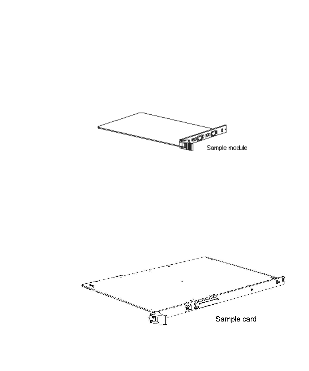
• Expansion cards and mo dules. The Wave IP 2500 supports two kinds of expansion
boards, cards and modules:
• Modules are partial-width boards that can be installed in module slots or universal
slots in the base unit or in Expansion Units (EXUs), described on page 3-4.
The following modules are available:
• Analog trunk module. Supports 8 analog FXO loop start or ground start
• Analog universal module. Supports 8 analog FXS station ports and 8 analog
Wave IP 2500 Installation Guide
trunk ports.
FXO loop start or ground start trunk ports.
• Cards are full-width boards that support higher port densities than modules. Cards
• Digital station module. Supports 12 digital station ports.
• T1 module with drop-and-insert (DNI) V.35 serial interface. Supports a
single T1 PRI digital trunk. It features an integrated CSU/DSU, and allows
shared data and voice services over a single T1 circuit.
can be installed in the universal slots in the base unit or in EXUs.
Page 28

Wave IP 2500 Installation Guide
For Review Only - Draft Document 09/07/07
COMPANY CONFIDENTIAL - DO NOT Distribute
The following cards are available:
• Analog station card. Supports 24 analog FXS station ports.
• Digital station card. Supports 24 digital station ports
• Expansion Units (EXU s). An EXU provides 2 universal slots that can each support one
module or card.Up to 4 modular EXUs can be mounted on top of the Wave IP 2500 base
unit. A fully expanded system with 4 EXUs provides 8 additional universal slots.
• Media Resource Modules (MRM) . Each Wave IP 2500 is pre-configured to support a
specific number of users and concurrent voice applications. To expand the system’s core
telephony, voice processing, and VoIP capabilities, you can install one of 3 available
MRM models that provide up to 128, 256, or 384 additional voice processing channels.
Only one MRM at a time can be installed on the ISC1.
/QWPVKPIVJG9CXG+2
The W av e IP 2500 can be rack moun ted, wall mou nted, or table mounte d. See “Environmen tal
Requirements” on page 2-2 for specific requirements on how to site the Wave IP 2500.
Caution: Due to the weight of the W ave IP 2500, moun t it with assistance whenever possible.
Review “Proper Lifting” on page 2-4 before rack mounting.
Important: Note the following:
• Do not place anything on or against the chassis that prevents proper ventilation. Be sure
to allow a minimum cooling clearance of 4 inches on all sides of the Wave IP 2500.
• To prevent the fans from pulling dust into the chassis, mount the Wave IP 2500 at least 2
feet (0.5 meters) above the floor. Do not operate the Wave IP 2500 at floor level.
4CEMOQWPVKPIVJG9CXG+2
The Wave IP 2500 is shipped r eady to be rack mounted . The Wave IP 2500 requires an EIA- or
IEC-compliant, 19-inch rack for proper mounting.
6QTCEMOQWPVVJG9CXG+2
1. Insert a rack mounting screw loosely into each side of the rack.
2. Slide the Wave IP 2500 chassis into the rack and hang it onto the scr e ws using either the
keyhole or slot on each mounting bracket. (This free s you from having to hold the chassi s
in place as you continue.)
Page 29
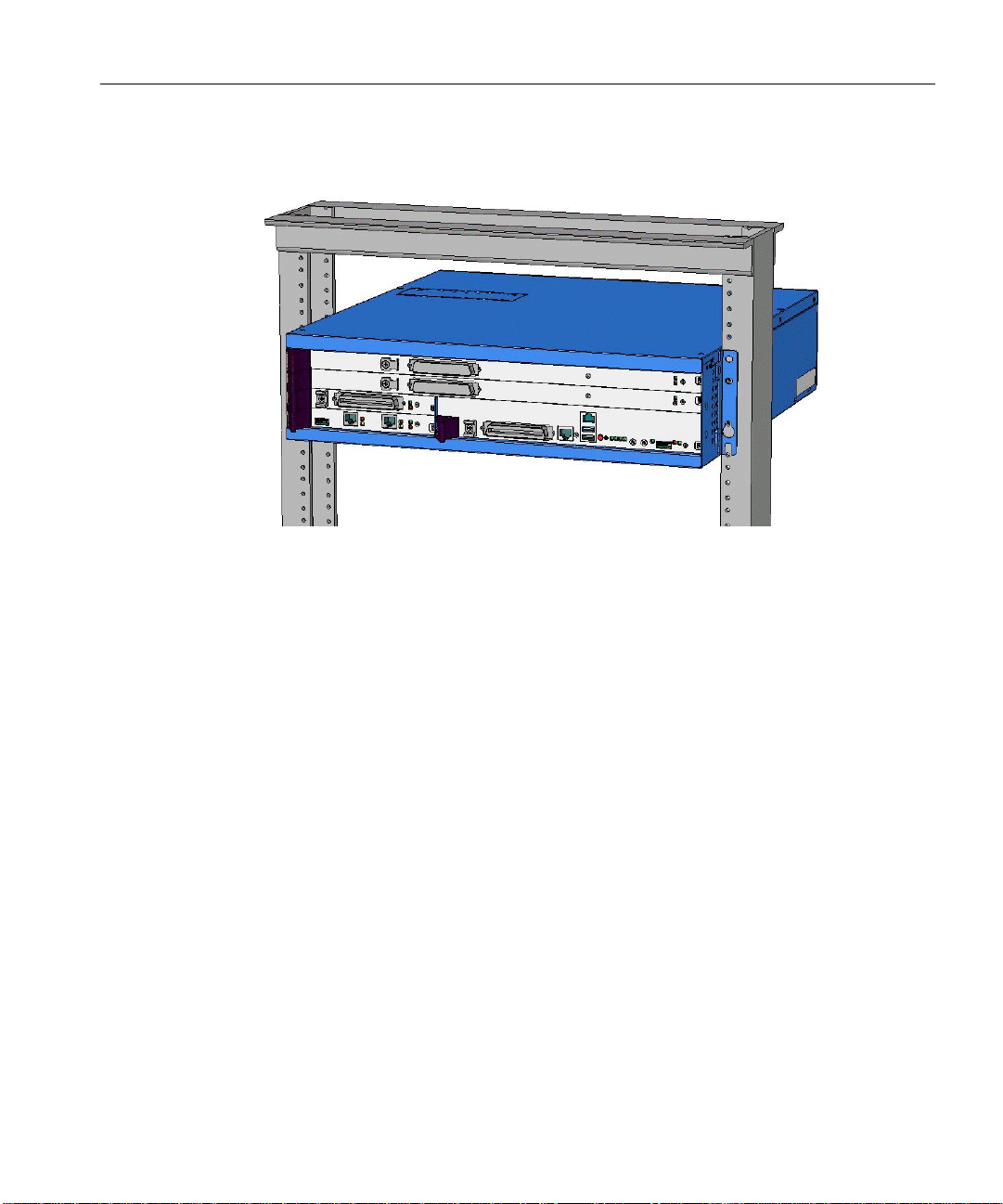
3. Tighten the screws, and then insert and tighten a second rack mounting screw in each
For Review Only - Draft Document 09/07/07
COMPANY CONFIDENTIAL - DO NOT Distribute
bracket. When successfully rack-mounted, the Wave IP 2500 chassis looks like this:
9CNNOQWPVKPIVJG9CXG+2
Wave IP 2500 Installation Guide
You can mount the Wave IP 2500 chassis onto a wall by first attaching a piece of prepared
plywood to studs in the wall, then attaching the chassis to the plywood.
Note: You can only wall mount the Wave IP 2500 chassis itself —wall mounting is not an
option if you are using one or more EXUs.
Caution: Note the following:
• Do not attach the chassis directly to a wall without using the plywood as a support—the
plywood must be firmly attached to wall studs in order to suppo rt the weight of the
chassis.
• Do not wall mount the chassis with the cards in a horizontal position. Only wall mount
the chassis with the cards in a vertical position, as in the picture on page 3-7.
Page 30
Wave IP 2500 Installation Guide
For Review Only - Draft Document 09/07/07
COMPANY CONFIDENTIAL - DO NOT Distribute
6QYCNNOQWPVVJG9CXG+2EJCUUKU
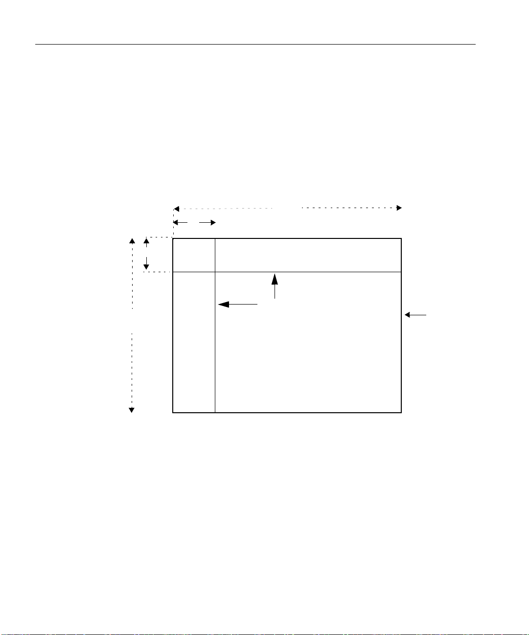
1. Prepare a piece of plywood that meets the following minimum dimensions for proper
ventilation and service access:
Thickness—0.75 inches (2 cm)
Height—24 inches (61 cm)
Width— 34 inches (86.4 cm)
2. Draw a vertical line on the plywood 4 inches (10.2 cm) from the left edge, and a
horizontal line 3-1/4 inches (8.3 cm) from the top edge:
3 1/4"
(8.3 cm)
34 “
4”
(10.2 cm)
(6.4 cm)
Two lines
24"
(61 cm)
Plywood
3. Locate supporting studs in your wall, and firmly attach the prepared piece of plywood to
the studs using the appropriate sc rews .
4. If the mounting brack ets are cu rrently installed on the front of the Wave IP 2500, remove
them.
Page 31

Wave IP 2500 Installation Guide
For Review Only - Draft Document 09/07/07
COMPANY CONFIDENTIAL - DO NOT Distribute
5. Position the mounting brackets at the bottom of each of the chassis side panels. Use a #2
Phillips screwdriver to fasten each mounting bracket to the chassis with the screws
provided.
6. With another person’s assistance, lift the Wave IP 2500 chassis and place it against the
wall-mounted plywood so that the side of the chassis with the fans faces to the left. Line
up the left side of the chassis with the vertical line that you drew on the plywood, and line
up the top of the chassis with the horizontal line that you drew.
7. Insert and tighten two self-threading #10 screws through each mounting bracket to
securely attach the chassis to the plywood. When successfully wall-mounted, the Wave
IP 2500 chassis looks like this:
Page 32

Wave IP 2500 Installation Guide
For Review Only - Draft Document 09/07/07
COMPANY CONFIDENTIAL - DO NOT Distribute
6CDNGOQWPVKPIVJG9CXG+2
T able mounting is a convenient solution for temporary or mobile operation requirements of the
Wave IP 2500. Do not place the Wave IP 2500 on the floor.
Caution: Ensure that the table supports a minimum weight load of 26 pounds (11.8 kg) for
the Wave IP 2500 chassis, as well as 19 pounds (8.6 kg) additional weight for each EXU that
you are using.
)TQWPFKPIVJG9CXG+2
Warning: The protective ground lug (earth contact) on the Wave IP 2500 chassis must be
permanently connected to earth.
Warning: The National Electrical Code requires that the telephone and electrical services
have a common ground. If separate grounds are used for telephone and electrical services, a
voltage di ffe rential coul d develop between the two services. This could expose you to an
electrical shock and damage the equipment.
6QITQWPFVJG9CXG+2
1. Locate the ground lug on the back of the Wave IP 2500.
2. Loosen the slotted scre w on the ground lug with a flat-head screwdriver.
3. Insert a 10- or 12-gauge stranded grounding wire into the ground lug opening.
4. Tighten the slotted screw.
Page 33

5. Connect the other end of the grounding wire to one of the following ground types:
For Review Only - Draft Document 09/07/07
COMPANY CONFIDENTIAL - DO NOT Distribute
• Power service ground
• Building steel ground
• Metallic cold water pipe that is bonded to a power ground (if permitted by local
building codes)
• Ground rod that is 5 feet l ong an d 5/8 i nch in diameter. (Use this option only if none
of the other options are available.)
%QPPGEVKPIVJG9CXG+2VQ[QWT.#0
This section describes h ow to connect the Wave IP 2500 to your LAN using a standard Eth ernet
cable. You can also connect the Wave IP 25 00 to your n etwork usi ng a network hu b, switch , or
router.
Note: The cabling for your LAN should be inst all ed by a net work cabl ing professional before
the arrival of the Wave IP 2500.
Wave IP 2500 Installation Guide
#DQWVVJG'VJGTPGVRQTVUQPVJG9CXG+2
There are 2 Ethernet ports located on the front of the ISC1, labeled ENET 1 and ENET 2.
Important: ENET 1 and ENET 2 are connected to an embedded switch in the ISC1 which
does not currently support the Spanning T ree algorith m. Cons equen tly, ENET 1 and ENET 2
must not bo th be simul taneously connected to another switch on your network. Connecting
both Ethernet ports to a switc h on your netw ork creates a loop that makes the embedd ed switch
inoperable, and the Wave IP 2500 will be cut off from your network.
• ENET 1 is the Wave IP 2500’s primary interface and under normal conditions it is the
only interface that should be connected to your network. You use ENET 1 to connect the
Wave IP 2500 to your network to provide Wave system functionality, for example access
to the Global Administrator Management Console, ViewPoint, VoIP station and trunk
resources, and so forth.
• ENET 2 should only be used in the following special circumstances:
• To directly connect the administrator PC to the Wave IP 2500 for system
configuration and administration, as described on page 4-4. (You can also connect
to the Wave IP 2500 from the administrator PC via a local or remote modem
connection, as described on page 4-7.)
Page 34

Wave IP 2500 Installation Guide
For Review Only - Draft Document 09/07/07
COMPANY CONFIDENTIAL - DO NOT Distribute
• As a backup in case ENET 1 is not functional. You can use ENET 2 to connect the
Wave IP 2500 to your network to provide Wave system functionality, as long as
ENET 1 is not used for the same purpose.
• For troubleshooting or diagnostic purposes, for example internal packet sniffing.
All packets exchanged between the Vertical Application Module (VAM) and the
embedded processor are copied to ENET 2 for diagnostic purposes. (Note that
packet copying does not significantly add to network traffic.)
6QEQPPGEVVJG9CXG+2VQ[QWT.#0
1. Locate the 8-pin modular RJ-45 Ethernet port labeled ENET 1 on the ISC1.
2. Connect one end of a standard, straight-through Ethernet cable to the ENET 1 port.
3. Connect the other end of the cable to your LAN.
%QPPGEVKPIVJG9CXG+2VQRQYGTCPFRQYGTKPIQP
Connect the Wave IP 2500 to a dedicated circuit using the supplied power cord. Do not use any
other power cord.
Page 35

Wave IP 2500 Installation Guide
For Review Only - Draft Document 09/07/07
COMPANY CONFIDENTIAL - DO NOT Distribute
6QEQPPGEVVJG9CXG+2VQRQYGTCPFRQYGTQP
1. Locate the power outlet and power toggle switch on the back of the Wave IP 2500.
2. Set the base unit po wer su pply r ocker swit ch and any EX U power sw itch ro cker switch es
located on the back of the Wave IP 2500 to the off position.
3. Connect the power cables from the main chassis and any EXUs to dedicated circuits.
4. Set each EXU’s rocker switch to the On position. (The EXU will not actually power on
until the main chassis is powered on.)
5. Power on the base unit by toggling the rocker switch.
6. Observe the status LEDs on the front of the Wave IP 2500 to ensure that the system
initialization completes successfully and that there are no component failures
For complete details of the information provided by the status LEDs, see Appendix B,
“Wave IP 2500 Status LEDs.”
%QPPGEVKPIVQVTWPMCPFUVCVKQPRQTVUQPVJG+5%
The RJ-12X port on the ISC1 provides the following:
• 4 analog FXO trunk ports that support loop start trunks only.
• 4 analog FXS station ports.
See Appendix A, ”Trun k and S tation Port s and Pinouts” fo r RJ-21X interf ace port des criptions
and pinout pairs for the ISC1.
6QEQPPGEVVQCPCNQIVTWPMCPFUVCVKQPRQTVUQPVJG+5%
1. Locate the RJ-21X port (labeled J1) on the ISC1.
2. Connect the analog station/trunk cable to the RJ-21X port.
Page 36

Wave IP 2500 Installation Guide
For Review Only - Draft Document 09/07/07
COMPANY CONFIDENTIAL - DO NOT Distribute
2QYGTHCKNQXGTUWRRQTV
The Wave IP 2500 provides for failover telephone service in the event of a power failure.
If the power fails, the analog phone connected to station port 1 on the ISC1 automatically
connects to the analog trunk plugged into t runk port 1, enabli ng the analog phone to make call s
even if the Wave IP 2500 is not functioning.
Hint: When setting up stations, connect station 1 to a ph one lo cated in an access ible area, suc h
as the lobby or front desk.
+PUVCNNKPIGZRCPUKQPEQORQPGPVU
This section describes how to install the following components to expand the Wave IP 2500
base unit:
• Expansion Unit (EXU). See the next section.
• Media Resource Module (MRM). See page 3-14.
• Expansion cards and modules. See page 3-15.
+PUVCNNKPI':7UQPC9CXG+2
You can install up to 4 EXUs on a Wave IP 2500.
6QKPUVCNNCP':7
1. Unplug the Wave IP 2500’s power cord, but do not disconnect the grounding wire.
2. Remove the connector hatch retention screws on the top of the Wave IP 2500 base unit,
and then remove the connector hatch.
3. Remove the backplane terminator from the base unit using both hands to pull it s tr a ight
up and out.
Caution: Make a note of the direction that the backplane terminator is facing when you
remove so that you can replace it the same way . A reversed b ackplane terminator can cause
malfunctions and damage equipment.
4. Open the side and rear latches on the EXU.
Page 37

Wave IP 2500 Installation Guide
For Review Only - Draft Document 09/07/07
COMPANY CONFIDENTIAL - DO NOT Distribute
5. Stack the EXU on top of the base unit or another EXU, aligning pins and electrical
connectors on the bottom of the EXU with the pins on the lower unit.
6. Press down gently to engage the backplane connector.
7. Engage the side and rear latches to secure the EXU.
8. If the Wave IP 2500 is rack-mounted, attach the EXU using 2 rack screws per side. If this
is the top-most EXU, go to step 10.
9. To install another EXU, remove the connector hatch from the top of the EXU that you
just installed. Repeat steps 4-8 to stack up to 4 EXUs.
10. Secure the backplane terminator to the topmost EXU.
Caution: Be sure to replace the backplane terminator facing the same direction it was
when you removed it. Also, p ay careful attention to pin ali gnment. Connector pin A 1 must
align with slot pin A1. DO NOT power on the Wave IP 2500 until you are certain that the
backplane terminator is installed correctly.
11. Replace the connector hatch on the topmost EXU and secure it with the retention screws.
12. Connect each EXU to power and ground it.
13. Reconnect the Wave IP 2500 to power.
Page 38

Wave IP 2500 Installation Guide
For Review Only - Draft Document 09/07/07
COMPANY CONFIDENTIAL - DO NOT Distribute
A Wave IP 2500 base unit with 1 EXU is shown below.
+PUVCNNKPIC/GFKC4GUQWTEG/QFWNG
Only one MRM can be installed on the ISC1.
1. Unplug the Wave IP 2500’s power cord, but do not disconnect the grounding wire.
2. Remove the I S C1 from the Wave IP 2500 base un i t. To do so:
• Label or note the position of any cables connected to the ISC1 faceplate.
• Disconnect all cables from the faceplate.
• Loosen the retention screws.
• Open the insertion lever at the left si de of th e faceplate, then pull firmly on the lever
to disengage the ISC1 from its slot.
3. Place the ISC1 on a static-safe work area.
4. Install the MRM standoffs on the ISC1 with the screws provided.
5. Align the MRM over the standoffs, and then fasten the retention screws in the corner
holes.
6. Plug the MRM ribbon connector into connector P4 (the light-blue 40-pin socket) on the
ISC1.
7. Re-install the ISC1 in the Wave IP 2500 base unit. To do so:
• Slide the ISC1 back into its slot.
• Engage the insertion lever .
• Fasten the retention screws.
• Reconnect cables to the faceplate.
Page 39

8. Reconnect the Wave IP 2500 to power.
For Review Only - Draft Document 09/07/07
COMPANY CONFIDENTIAL - DO NOT Distribute
+PUVCNNKPIGZRCPUKQPOQFWNGUCPFECTFU
This section provides guidelines for installing all modules and cards. See “Connecting modules
and cards” on page 3-16 for information on connecting trunks, stations, and other devices to
specific modules and cards after you have installed them.
Caution: The Wave IP 2500’s analog station interface is not designed to withstand surges
commonly associated with wires that are exposed to the external environment. Do not route the
wires connecting analog station cards or modules to stations outside the building where the
Wave IP 2500 is located.
Note: To install a Media Resource Module, see the instructions starting on page 3-14.
6QKPUVCNNOQFWNGUCPFECTFU
1. Unplug the Wave IP 2500’s power cord and the power cords of all EXUs, but do not
disconnect the grounding wires.
2. Remove the blank module or universal slot faceplate.
Wave IP 2500 Installation Guide
3. Insert modules and cards carefully.
• Note the position of the circuit board installation guides—there are 2 guides per
slot:
• Modules align with the bottom guide.
• Cards align with the top guide.
• Note the position of slot connectors:
• The ISC1 slot and module slots have a single slot connector.
• Universal slots have 2 slot connectors:
• Modules connector to the bottom slot connector.
• Cards connect to the top slot connector
4. Seat the module or card properly for good electrical connection. Engage the black
insertion lever, and tighten all faceplate mounting screws.
5. To install a partial-width module in a full-width universal slot, use a Wave IP 2500
module converter. First, screw the module into the converter, and then insert the
converter into the universal slot.
Page 40

Wave IP 2500 Installation Guide
For Review Only - Draft Document 09/07/07
COMPANY CONFIDENTIAL - DO NOT Distribute
6. Install blank faceplates on all unused slots.
7. Reconnect the Wave IP 2500 and all EXUs to power.
/QFWNGCPFECTFUVCVWU.'&U
Each module and card has a pair of LEDs that indicate the item’s status:
4GCF[
ITGGP
ON OFF Normal state—module or card is fully operations.
OFF ON Initial state when Wave IP 2500 is powered on; module or
ON ON Software is initializing.
OFF OFF No power to the module or card, or a fatal error has
Note: The T1 module with drop-and-insert V.35 serial interface has an additional set of status
'TTQT
TGF
lights for the T1 and serial ports that are located to the left of the module status LEDs.
%QPPGEVKPIOQFWNGUCPFECTFU
This section provides i nstruction s for connecti ng trunks, s tations, and other devices t o modul es
and cards.
Important: Before performing the steps in the following sections, ensure that the following
tasks have been completed, depending on your configuration:
• The punchdown block or multiport adapter has been properly wired by a
telecommunications professional.
5VCVWU
card has not yet initialized.
If module or card remains in this state after the Wave IP
2500 is fully operational, modu le or c ard initialization has
failed.
occurred.
Page 41

• Analog and T1 trunks have been installed by your service provider.
For Review Only - Draft Document 09/07/07
COMPANY CONFIDENTIAL - DO NOT Distribute
• Incoming analog DID trunks have been tested to ensure no voltage is present, as well as
to verify that they are DID trunks.
See the following sections for information about connecting each of the supported modules and
cards:
• Analog trunk module. See page 3-17.
• Analog universal module. See page 3-18.
• Digital station module. See page 3-18.
• T1 module with drop-and-insert V.35 serial interface. See page 3-19.
• Analog station card. See page 3-19.
• Digital station card. See page 3-20.
Caution: Ensure that only analog phones are connected to analog station ports and only
digital phones to digital station ports. This will prevent damage to the analog circuitry.
%QPPGEVKPIVJGCPCNQIVTWPMOQFWNG
Wave IP 2500 Installation Guide
The analog trunk module provides 8 analog FXO loop start or ground start trunk ports. It is a
partial-width module that can be installed in any module slot or in any universal slot via a
module carrier .
See Appendix A, ”Trun k and S tation Port s and Pinouts” fo r RJ-21X interf ace port des criptions
and pinout pairs for the analog trunk module.
6QEQPPGEVVJGCPCNQIVTWPMOQFWNG
1. Locate the RJ-21X port on the module.
2. Connect the analog trunk or station cable to the RJ-21X port.
Page 42

Wave IP 2500 Installation Guide
For Review Only - Draft Document 09/07/07
COMPANY CONFIDENTIAL - DO NOT Distribute
%QPPGEVKPIVJGCPCNQIWPKXGTUCNOQFWNG
The analog universal module provides the following:
• 8 analog FXO trunk ports, supporting loop start, ground start, and analog DID trunks
(analog DID trunks support inbound calling only).
• 8 analog FXS station ports.
The analog universal module is a partial-width module that can be installed in any module slot
or in any universal slot via a module carrier.
See Appendix A, ”Trunk and S tation Ports an d Pinouts” fo r RJ-21X interf ace port descriptions
and pinout pairs for the analog universal module.
6QEQPPGEVVJGCPCNQIWPKXGTUCNOQFWNG
1. Locate the RJ-21X port on the module.
2. Connect the analog station/trunk cable to the RJ-21X port.
%QPPGEVKPIVJGFKIKVCNUVCVKQPOQFWNG
The digital station module provides 12 digital station ports. It is a partial-width module that can
be installed in any module slot or in any universal slot via a module carrier.
See Appendix A, ”Trunk and S tation Ports an d Pinouts” fo r RJ-21X interf ace port descriptions
and pinout pairs for the digital station module.
6QEQPPGEVVJGFKIKVCNUVCVKQPOQFWNG
1. Locate the RJ-21X port on the module.
2. Connect the RJ-21X cable from your punchdown block or multiport adapter to the port.
Page 43

Wave IP 2500 Installation Guide
For Review Only - Draft Document 09/07/07
COMPANY CONFIDENTIAL - DO NOT Distribute
%QPPGEVKPIVJG6OQFWNGYKVJFTQRCPFKPUGTV8UGTKCNKPVGTHCEG
The T1 module with drop-and-insert (DNI) V.35 serial interface supports one T1 o r ISDN PRI
digital trunk with an integrated CSU/DSU to provide shared data and voice services over a
single T1 circuit. There are 2 connectors on the T1 module:
• The RJ-48C port is used to connect to the T1 or ISDN PRI network interface.
• The DB-60 port provides V.35 serial comm unications for data connections, for example
to connect to the DB-60 cable from an external router.
The T1 module is a partial-width module that can be installed in any module slot or in any
universal slot via a module carrier.
6QEQPPGEVVJG6OQFWNG
1. Locate the RJ-48C port and DB-60 connector on the module.
2. Connect the T1 cable to the RJ-48C port.
3. Connect the serial cable from your external router to the DB-60 port.
The serial cable may be either a DB-60 male to DB-60 male cable, or a DB-60 male to
V.35 female DCE cable. In either case the DB-60 male connector goes to the DB-60
female port on the ISC1.
Caution: Use care when connecting or disconnecting the serial cable. Because of the
connector’s small size and high pin count, pins on the cable connector can be easily bent
and the DB-60 port may be damaged.
%QPPGEVKPIVJGCPCNQIUVCVKQPECTF
The analog station card provides 24 analog FXS station ports. It is a full-width card that can be
installed in any universal slot.
See Appendix A, ”Trun k and S tation Port s and Pinouts” fo r RJ-21X interf ace port des criptions
and pinout pairs for the analog station card.
6QEQPPGEVVJGCPCNQIUVCVKQPECTF
1. Locate the RJ-21X port on the card.
2. Connect the RJ-21X cable from your punchdown block or multiport adapter to the port
on the Wave IP 2500 using a male RJ-21X connector.
Page 44

Wave IP 2500 Installation Guide
For Review Only - Draft Document 09/07/07
COMPANY CONFIDENTIAL - DO NOT Distribute
%QPPGEVKPIVJGFKIKVCNUVCVKQPECTF
The digital station card provides 24 digital station ports. It is full-width card that can be installed
in any universal slot.
See Appendix A, ”Trunk and S tation Ports an d Pinouts” fo r RJ-21X interf ace port descriptions
and pinout pairs for the digital station card.
6QEQPPGEVVJGRQTVFKIKVCNUVCVKQPECTF
1. Locate the RJ-21X port on the card.
2. Connect the RJ-21X cable from your punchdown block or multiport adapter to the port.
%QPPGEVKPICOWUKEQPJQNF/1*U[UVGO
A music-on-hold device plays prerecorded mus ic or messages to callers—either fro m a tape or
CD—when they are placed on hold or while being transferred.
The Wave IP 2500 is compatible with most standard music-on-hold devices that connect via a
3.5 mm stereo plug. If a cable is not provided, you must purchase one separately.
Note: Although a stereo cable is required, music on hold only plays in mono.
Caution: Always follow t he instructions supp lied by the manufacturer of your music-on-hold
device when installing and connecting the dev ice to avoid po ssible injury to yourself or damage
to the equipment.
6QEQPPGEVCOWUKEQPJQNFFGXKEG
1. Locate the audio input port (labeled Audio In) on the ISC1.
Page 45

2. Connect the cable from your music-on-hold device to the port.
For Review Only - Draft Document 09/07/07
COMPANY CONFIDENTIAL - DO NOT Distribute
3. Enable music on hold in the General Settings applet of the Global Administrator
Management Console. See the Wave Global Administrator Guide for more information.
%QPPGEVKPICRCIKPIU[UVGO
A paging system allows Wave users to make public announcements over a loudspeaker.
The W ave IP 2500 is compatible with most standard paging systems that connect via a 3.5 mm
stereo plug. If a cable is not provided, you must purchase one separately.
Note: Although a stereo cable is required, only one channel is used for paging.
Caution: Always follow t he instructions supp lied by the manufactu rer of your pagi ng system
when installing and connecting the system to avoid possible injury to yourself or damage to the
equipment.
1. Locate the audio output port (labeled PA Out) on the front of the ISC1.
Wave IP 2500 Installation Guide
2. Connect the cable from your paging system to the port.
3. Enable paging in the General Settings applet of the Global Administrator Management
Console. See the Wave Global Administrator Guide for more information.
Page 46

For Review Only - Draft Document 09/07/07
COMPANY CONFIDENTIAL - DO NOT Distribute
Page 47

Wave IP 2500 Installation Guide
For Review Only - Draft Document 09/07/07
COMPANY CONFIDENTIAL - DO NOT Distribute
Chapter 4
+PKVKCN%QPHKIWTCVKQP
The Vertical Wave IP 2500 is delivered with all hardware and software components installed.
This chapter describes the following tasks that you must perform to initially con figure the
Vertical Wave IP 2500:
1. Obtaining all required HotFixes. See page 4-2.
2. Configuring the administrator PC. See page 4-2.
3. Connecting to the Vertical Wave IP 2500 via your LAN or a modem. See page 4-4.
4. Applying all required HotFixes. See page 4-9.
5. Adding the Wave IP 2500 to your LAN. See page 4-11.
This chapter also explains how to perform the following tasks:
• Power-cycling the Wave IP 2500. See page page 4-15.
• Resetting the Wave IP 2500 IP addresses to the factory defaults. See page 4-16.
• Using the Service Account Utility any time that you change the default Wave
domain name, account name, or account password. See page 4-17.
9JGTGVQIQPGZV
After you complete the tasks described in this chapter, go to Chapter 5, “Entering and
Activating Wave Licenses.”
Page 48

Wave IP 2500 Installation Guide
For Review Only - Draft Document 09/07/07
COMPANY CONFIDENTIAL - DO NOT Distribute
1DVCKPKPICNNTGSWKTGF*QV(KZGU
Before you begin initial configuration of your Wave IP 2500, contact your Vertical
representative to obtain any required HotFixes and other critical information. Once you have
obtained the HotFix CAB files from your Vertical representative, place them on the hard drive
of the PC that you will use to administer the Wave IP 2500.
Important: Be sure to move the HotFix CAB files to the administrator PC before performing
the steps in the next section, where you will change the IP address of the administrator PC. Once
you change the IP address of the administrator PC, that PC will be dedicated to the Wave IP
2500 and you will no longer be able to access your network or go out on the Internet from it.
%QPHKIWTKPIVJGCFOKPKUVTCVQT2%
Before you can connect to the Wave IP 2500 for initial configuration, you must configure
TCP/IP on the administrator PC that you will use to connect with.
#FOKPKUVTCVQT2%TGSWKTGOGPVU
The administrator PC must meet the following minimum requirements:
• A Pentium 233 MHz PC running Microsoft Windows 2000 or Windows XP
•64 MB RAM
• LAN or WAN connectivity through an Ethernet card or modem
• Microsoft Internet Explorer 6.0 SP1. Be sure that Internet Explorer is configured to
connect directly to the Internet—do not connect using a defined proxy server.
Note: You may require your Microsoft operating system disks in order to install components
necessary for connecting to the Wave IP 2500.
%QPHKIWTKPI6%2+2QPVJGCFOKPKUVTCVQT2%
1. Click Start > Control Panel > Network Connections.
2. Right-click Local Area Connection and then click Properties. The Local Area Connection
Properties dialog box opens.
Page 49

Wave IP 2500 Installation Guide
For Review Only - Draft Document 09/07/07
COMPANY CONFIDENTIAL - DO NOT Distribute
3. Select the entry for Internet Protocol (TCP/IP), and then click Properties. The Internet
Protocol (TCP/IP) Propert ies dialog box opens.
4. On the General tab, click Use the following IP address, and enter the following
information:
IP address: 192.168 .205.x . “x” can be an y num ber bet ween 2 and 2 54, excep t f or 10
(192.168.205.10 is reserved for the IP address of the Integrated Services Card
(ISC1) on the Wave IP 2500).
Subnet mask: 255.255.255.0
5. Click OK to save your changes, and again to exit the Local Area Connection Properties
dialog box.
6. If you are prompted to restart the your computer, do so.
Page 50

Wave IP 2500 Installation Guide
For Review Only - Draft Document 09/07/07
COMPANY CONFIDENTIAL - DO NOT Distribute
%QPPGEVKPIVQVJG8GTVKECN9CXG+2
After configuring the TCP /IP proto col on the admini strato r PC, you are ready t o conne ct to the
Wave IP 2500 for initial configuration.
You can connect to the Wave IP 2500 in any of the following ways:
• Network connection. See the next section.
• Local or remote modem connection. See page 4-7.
%QPPGEVKPIVQVJG9CXG+2XKC[QWTPGVYQTM
This section describes how to connect to the Wave IP 2500 from the administrator PC using a
standard Ethernet cable. You can also connect to the W ave IP 2500 using a network hub, switch,
or router.
1. Connect one end of a st andar d, s trai gh t-t hrou gh Ethernet cable to the network card in the
administrator PC. Connect the other end of the cable to the RJ-45 Ethernet port labeled
ENET 1 on the front of the ISC1.
Important: ENET 1 is the Wave IP 2500’s primary interface and under normal
conditions it is the only interface that should be conn ect ed to your L AN . The port labeled
ENET 2 is only used in special circumstances, as described in “About the Ethernet ports
on the Wave IP 2500” on page 3-9.
2. Launch Microsoft Internet Explorer. If the administrator PC is running Windows XP
Service Pack (SP) 2, go to step 3. Else, go to step 4.
3.
Warning: In Microsoft Windows XP SP 2, Microsoft enhanced the default
browser security in Internet Explorer. These security defaults affect the
functionality of Global Admin i st rator Management Console (for example, by
disabling or hiding some appl ets ). To ensure that you do not encounter any
problems when using the Global Administrator Management Console, perform the
following steps:
• On the administrator PC, in Internet Explorer, click Tools > Internet Options.
• Click the Privacy tab.
• In the Pop-up Blocker section, click Settings.
Page 51

Wave IP 2500 Installation Guide
For Review Only - Draft Document 09/07/07
COMPANY CONFIDENTIAL - DO NOT Distribute
• In the Address of Web site to allow text box, type one of the followin g:
• http://192.168.205.1, the default IP address of the Vertical Application Module
(VAM) in the Wave IP 2500
• http://yourIP2500servername
• Click Close and then OK to save your changes.
If you entered the VAM’s IP address (the default is http://192.168.205.1), perform
the following additional steps. If you entered your server name, go to step 4.
• In Internet Explorer, click Tools > Internet Options.
• On the Security tab, select Trusted Sites, and then click Sites.
• Uncheck Require server verification (https:) for all sites in this zone.
• In the Add this Web site to the zone text box, type the VAM’s IP address (the default
is http://192.168.205.1), and then click Add to add it to the Web Sites list.
• Click OK twice to save your changes.
4. On the administrator PC, browse to the following location to open the Global
Administrator Management Console:
http://192.168.205.1/ioadmin
Important: If this is the first time that you are logging on to the Wave IP 2500 from this
administrator PC and you are prompted to install a specific version of the Java Runtime
Environment, do so. Failure to install the correct version may prevent some Global
Administrator Management Console features from working correctly.
5. The Log On screen opens in your browser:
Page 52

Wave IP 2500 Installation Guide
For Review Only - Draft Document 09/07/07
COMPANY CONFIDENTIAL - DO NOT Distribute
6. Enter the following defaults, and then click Log On. (Note that Password is
case-sensitive.)
User Name: GlobalAdministrator
Password: Vertical4Vo IP !
Note: If any other users are logged on to the Wave IP 2500, a list of logged-on users is
displayed (this will not be the case when you ini tially configure your W ave IP 2500). Clic k
OK to close the dialog box and continue.
7. The Global Administrator Management Console opens. You are now successfully
connected to the Wave IP 2500.
Go to “Applying all required HotFixes” on page 4-9.
Page 53

%QPPGEVKPIVQVJG9CXG+2XKCCOQFGO
For Review Only - Draft Document 09/07/07
COMPANY CONFIDENTIAL - DO NOT Distribute
You can use a local or remote modem connection to connect to the Wave IP 2500 from the
administrator PC for system configuration.
The following terms are used throughout this section:
• Wave modem: The answering modem, included with the Wave IP 2500 base unit and
located on the ISC1. The Wave modem can be reached through any trunk port or any
analog station port on the Wave IP 2500. The IP address of the Wave modem is always
192.168.210.1.
• Client modem: The calling modem, installed on the administrator PC. The following
client modems have been certified for use with the Wave IP 2500. Other modems may
also work, but only these models have been tested so far by Vertical. The IP address of
the client modem is in the range of 192.168.210.2 to 192.168.210.10.
• USRobotics USB Mini Faxmodem Model 5635
• USRobotics Internal 56K Faxmodem PCI Model 5699B
• USRobotics Serial V.90 56K Sportseter Model 0701
• Zoom V.90/V.92 Faxmodem Series 0269
• Remote connection: A modem connection made through a trunk port on the Wave IP
2500. By default, the Wave modem is configured to answer on the third analog trun k port
of the ISC1. You can use the Hunt Groups and Trunk Groups applets in the Global
Manager Administrative Console to configure the Wave modem to answer on any other
digital or analog trunk. (Modem throughput will often be much better on a digital trunk.)
• Local connection: A modem connection made through an analog station port on the
W av e IP 250 0. Altho ugh less useful than a remote connection, a l ocal modem connect ion
can be made through any analog station port on the Wave IP 2500. The default Wave
modem extension is 570.
Wave IP 2500 Installation Guide
Page 54

Wave IP 2500 Installation Guide
For Review Only - Draft Document 09/07/07
COMPANY CONFIDENTIAL - DO NOT Distribute
%QPPGEVKPIVQVJG9CXG+2XKCCOQFGOEQPPGEVKQP
Important: Before proceeding, install the modem on the administrator PC according to the
manufacturer’s documentation.
Note: The following procedures desc rib e the steps t o per form on an administrator PC run ni ng
Windows XP. The steps may be different on a PC running another Windows operating system.
6QEQPHKIWTGVJGENKGPVOQFGOQPVJGCFOKPKUVTCVQT2%
1. On the administrator PC, select Start > Control Panel > Network Connections > Create a
new connection. When the New Connection Wizard starts, click Next to continue.
2. In the Network Connection Type screen, select Connect to the network at my workplace,
and then click Next.
3. In the Network Connection screen, select Dial-up connection and then click Next.
4. In the Connection Name screen, enter a name for the connection, for example, Wave
Modem Connection. Click Next to continue.
5. If you have another devi ce (besi des th e client mode m) connected to the administrator PC,
in the Select a Device screen, select the checkbox for the modem that you added. Click
Next to continue.
6. In the Phone Number to Dial screen, enter the Phone number:
• For a remote connection, enter the 7 or 10 digit phone number that will ring the
desired trunk.
• For a local connection, enter the extension number for the Wave modem (the default
is 570).
Click Next to continue.
7. In the Connection Availability screen, specify whether this connection will be available
to all users or just to yourself. Choose Anyone's use or My use only, depending on your
security requirements. Click Next to continue.
8. In the final screen, click Finish. The Connect dialog box opens automatically after a few
moments. Go to the next section.
Page 55

Wave IP 2500 Installation Guide
For Review Only - Draft Document 09/07/07
COMPANY CONFIDENTIAL - DO NOT Distribute
6QEQPPGEVVQVJG9CXG+2XKCCNQECNOQFGOEQPPGEVKQP
1. Select Start > Settings > Network Connections and then click the new connection (for
example, Wave Modem Connection).
2. In the Connect dialog box, enter the following information, and then click Connect.
• User name: GlobalAdministrator
• Password: Vertical4VoIP!
Note: Password is case-sensitive.
3. Once you have established the connection, you can do the following:
• To start the Global Administrator Management Console on the Wave IP 2500 via
the modem connection, point your browser to 192.168.210.1, the IP address of the
Wave mo dem.
Important: You can perform all Management Console tasks via the modem
connection, but be aware that HotFix upgrades will be very slow, typically taking
several hours to complete, and software upgrades will take even longer. HotFix or
software upgrades will run much faster if you connect to the Wave IP 2500 via your
network, as desribed on page 4-4.
• To establish a Remote Desktop session on the Wave IP 2500 via the modem
connection, start Remote Desktop and then enter 192.168.210.1 (the IP address of
the Wave modem) in the Computer field.
Go to the next section.
#RRN[KPICNNTGSWKTGF*QV(KZGU
This section describes how to use the Software Upgrade applet to apply one or more HotFixes
to upgrade the Wave IP 2500. The Software Upgrade automatically restarts the Wave IP 2500
as required by the HotFixes that you apply.
Important: You must apply all required HotFixes before performing any subsequent
configuration steps described in this chapter.
Page 56

Wave IP 2500 Installation Guide
For Review Only - Draft Document 09/07/07
COMPANY CONFIDENTIAL - DO NOT Distribute
+UUWGUVJCVECPRTGXGPVQTCHHGEVCPWRITCFG
Before the upgrade process begins, the Software Upgrade applet runs several checks to verify
that the Wave IP 2500 is ready to be upgraded.
• If the company name entered in the General Settings applet in the Global Administrator
Management Console includes quotation marks (“”), the upgrade of Call Detail Report
data cannot proceed. Be sure you don't use quotation marks in the Company Name field.
• If there are any problems with the har d drive on which y ou are appl ying th e upgrade, you
will receive a message indicating that you must restart the Wave IP 2500 before you can
upgrade. Note that the restart will take noticeably longer than normal, because the hard
drive problems are being repaired.
• If the Software Upgrade applet encounters problems with the database or detects certain
critical errors in the event log, the upgrade will not proceed. If the upgrade process fails
to proceed as expected, contact your Vertical representative for assistance.
To apply one or more HotFixes
1. From the administrator PC, log on to the Global Administrator Management Console
according to steps 4-5 on page 4-5.
2. Click Software Upgrade in the General Administration section. The Software Upgrade
applet starts, and the Upgrade button is automatically active.
3. Click Browse and navigate to the directory containing the HotFix CAB file(s).
4. Select the CAB file to apply and click Open. The CAB file is displayed in the Filename
field.
5. Do one of the following:
• To apply a single HotFix, click Add and Start Upgrade. The HotFix is uploaded to
the Wave IP 2500, and the upgrade process begins.
• To apply multiple HotFixes in the same upgrade, click Add. Repeat step 5 for each
HotFix to be loaded.
The HotFixes will be installed in the order listed. To re-order the list, select a
HotFix and then click UP or DOWN. When you are satisfied with the list of
HotFixes, click the Start button below the Upgrade List to initiate the upgrade.
Note: Follow the instructions included with each HotFix, Unless otherwise
specified, best practice is to load HotFixes in numerical order.
Page 57

Wave IP 2500 Installation Guide
For Review Only - Draft Document 09/07/07
COMPANY CONFIDENTIAL - DO NOT Distribute
6. Once the upgrade process starts, you will be alerted on the progress of the upgrade via the
SNMP Alarms applet. Minimize the SNMP Alarms window so that you can see the next
message.
7. When you see the following message, click Done to close the Software Upgrade applet
and return to the Global Administrator Management Console.
“Upgrade Status Upgrade request successful. InstantOffice System upgrade will
start momentarily.”
8. Restore the SNMP Alarms window and monitor it until the “Rebooting InstantOffice”
entry appears. The Wave IP 2500 restarts one or more times, depending on the number of
restarts required by the HotFixes that you installed. This process may take 10 minutes or
more.
Note: HotFix installation is complete when the blink pattern of the red LED at the far right
of the ISC1 changes from a fast double blink to a steady single blink.
9. Once the Wave IP 2500 restarts for the final time, log on again t o the Wave IP 2500 again
using your Wave user name and password.
10. To verify that the HotFixes were applied successfully, click Software Versions in the
General Administration section of the Global Administrator Management Console. The
top entry shows the latest release. HotFix entries are listed in the order that they were
applied, using the following format:
[Day] [Date] [Year] [Time]= [HotFix information]
#FFKPIVJG9CXG+2VQ[QWT.#0
Before performing the following tasks according to the steps in this section, be sure that you
have successfully connected the Wave IP 2500 to your LAN according to the steps on page 3-9.
• Changing the IP network settings of the following components on the Wave IP 2500:
• Integrated Services Card (ISC1)
• Vertical Application Module (VAM)
• Media Resource Module (MRM), if one is installed
• Configuring the Wave IP 2500 for one-click license activation. In order to activate
your Wave licenses using one-click activation, the Wave IP 2500 must be able to connect
to the Internet and communicate with the Vertical Activation Server. Make sure that the
settings in the IP Network Settings dialog box are correctly set so that gateway and DNS
servers have external access. (For more about license activation, see page 5-6.)
Page 58

Wave IP 2500 Installation Guide
For Review Only - Draft Document 09/07/07
COMPANY CONFIDENTIAL - DO NOT Distribute
• Adding the Wave IP 2500 t o your Win dows do main. You should add the Wave IP 2500
to your domain if you are using one, so that users can install or upgrade the ViewPoint
workstation application without needing to enter network credentials, a very error-prone
task. (For more about installing workstation applications, see page 6-4.)
Caution: Adding the Wave IP 2500 to your company’s Windows domain makes it
subject to the policies and domain settings established b y your IT d epartment. For
example, the Wave IP 2500 may start to download Microsoft updates automatically. Be
aware that these policies and settings may affect, interfere, or hinder system operation.
• Changing the default name of the Wave IP 2500. By default, each Wave IP 2500 is
named “default”. If more than one Wave IP 2500 is on the same network segment, each
should have a unique name to avoid problems.
#FFKPICPFEQPHKIWTKPIVJG9CXG+2QP[QWT.#0
1. From the administrator PC, log on to the Global Administrator Management Console on
the Wave IP 2500 using your Wave user name and password.
6QEJCPIGVJG+2PGVYQTMUGVVKPIUQPVJG9CXG+2
Caution: Be sure to make all IP network setting changes outside of business hours to
avoid momentary interruptions to digital signaling (for example, key presses or LCD
updates to digital phones) while the new settings are applied.
You should make all IP network setting changes for the ISC1, VAM, and MRM at the
same time.
2. Select IP Network Settings in the Data Administration section.
Page 59

Wave IP 2500 Installation Guide
For Review Only - Draft Document 09/07/07
COMPANY CONFIDENTIAL - DO NOT Distribute
3. In the IP Network Settings dialog box, select the Integrated Services Card from the
Network Interfaces dropdown list.
4. On the IP Address tab, accept the factory defaults for the following settings, or assign
different ones.
• IP Address: IP address of the ISC1. The default is 192.168.205.10.
• Subnet Mask: The network subnet mask for the ISC1. The default is 255.255.0.0.
• Default Gateway: The default gateway for the ISC1. The default is 0.0.0.0.
Important: The ISC1, VAM, and MRM (if one is installed) IP addresse s all need to be
on the same subnetwork. The Subnet Mask and Default Gateway settings should be the
same for all components.
5. Set the VAM IP network information by selecting the Vertical Wave Application Module
from the Network Interfaces drop-down list, and then perform steps 3-4.
6. If an MRM is installed on your Wave IP 2500, select Media Resource Module from the
list and perform steps 3-4.
Note: Depending on the model, an MRM will have 1, 2, or 3 IP addresses.
7. If you have no further chamges to make, go to step 15.
Page 60

Wave IP 2500 Installation Guide
For Review Only - Draft Document 09/07/07
COMPANY CONFIDENTIAL - DO NOT Distribute
6QEQPHKIWTGVJG9CXG+2HQTQPGENKEMNKEGPUGCEVKXCVKQP
8. Verify that that the gateway and DNS servers have external access so that they can
connect to the Internet and communicate with the Vertical Activation Server.
9. Click the DNS tab.
10. Enter the DNS server’s IP address in the DNS Service Search Order text box, and then
click Add.
11. If you have no further changes to make, go to step 15.
6QCFFVJG9CXG+2VQ[QWT9KPFQYUFQOCKP
12. On any tab, click Join Domain. To remove the Wave IP 2500 from your Windows
domain, cl ick Remov e.
13. If you have no further changes to make, go to step 15.
Page 61

6QEJCPIGVJGPCOGQHVJG9CXG+2
For Review Only - Draft Document 09/07/07
COMPANY CONFIDENTIAL - DO NOT Distribute
14. On any tab, type the new name in the Host Name text box.
15. Click Apply and then click Done to save all of your changes. Note the following:
• If you changed IP network settings or configured the Wave IP 2500 for one-click
license activation, your changes take effect immediately. You do not need to restart
the Wave IP 2500.
• If you changed the Wave IP 2500’s Host Name, your change will not take effect
until the next time that the Wave IP 2500 is restarted.
2QYGTE[ENKPIVJG9CXG+2
This section describes various shutdown and restart procedures.
6QTGUVCTVVJG9CXG+2YKVJQWVRQYGTKPIQHH
1. In the Global Admi n istrat or Management Console, choose Restart System in the General
Administration section.
2. In the Restart system dialog box, specify how many seconds should elapse before the
system restarts.
3. Click Restar t .
Wave IP 2500 Installation Guide
4. Click Yes at the confirmation screen, and then click OK to restart the Wave IP 2500.
6QUJWVFQYPCPFRQYGTQHHVJG9CXG+2
1. Press and hold the red button on the ISC1.
2. When you observe the fo llo wing p atter n on the ISC 1 sys tem status LEDs, releas e the r e d
button:
5VCVWU .'& .'& .'& .'&
Shutdown butto n press detec ted. System
shutdown initiated.
System shutdown begins, and when complete, the Wave IP 2500 powers itself off.
Green Blinking red /
solid green
Blinking green
/ blinking red
Blinking green
Page 62

Wave IP 2500 Installation Guide
For Review Only - Draft Document 09/07/07
COMPANY CONFIDENTIAL - DO NOT Distribute
6QTGUVCTVVJG9CXG+2CHVGTRQYGTKPIQHH
1. Turn the power switch on the back of the Wave IP 2500 off, wait 30 seconds, and then
turn the power switch on.
2. When you observe the following pattern on the ISC1 system status LEDs, the Wave IP
2500 is fully operational:
5VCVWU .'& .'& .'& .'&
Normal firmware operation. Green Blinking red /
solid green
Note: For a detailed description of the system status LED s equence during normal sys tem
Blinking green Blinking green
startup, see “Normal firmware boot sequence” on page B-1.
4GUGVVKPIVJG9CXG+2+2CFFTGUUGUVQVJGHCEVQT[FGHCWNVU
If you lose or forget the current ISC1 or VAM IP address setti ngs, you can reset them to the
factory default settings.
1. Shut down the Wave IP 2500, and turn off the power supply switch on the back of the
chassis.
2. Press and hold the red button on the front of the ISC1.
3. While continuing to press the red button, turn the power supply switch back on. Wait for
a few seconds until you observe the following status indicator LED sequence, and then
release the red button.
5VCVWU .'& .'& .'& .'&
Red button press dete cted at power on.
Programming factory default IP
settings.
Red off off Red
Redboot started. Factory default IP
address settings have been applied.
Red off off Green
Page 63

7UKPIVJG5GTXKEG#EEQWPV7VKNKV[
For Review Only - Draft Document 09/07/07
COMPANY CONFIDENTIAL - DO NOT Distribute
If at any time you chang e the default dom ain name (io-default), account (GlobalAdministrator),
or account password (Vertical4V oIP!), yo u must run the Service Account utility according to the
following steps:
1. From the administrator PC, log on to the Global Administrator Management Console on
the Wave IP 2500 using your Wave user name and password.
2. Click the Sy stem Desktop icon at the to p right of the G lobal Admi ni strator Management
Console.
3. Click OK to clear the warning message.
4. In the Logon to Windows dialog box, enter your Wave user name and password, and then
click OK.
5. Choose Start > All Programs > TVAccUtl.
6. Enter the Domain name, Account name, and Password for the domain.
7. Click OK to save you r changes. C lick OK to acknowledge th e message indicatin g that the
service account information has been updated successfully.
Wave IP 2500 Installation Guide
Page 64

For Review Only - Draft Document 09/07/07
COMPANY CONFIDENTIAL - DO NOT Distribute
Page 65

Wave IP 2500 Installation Guide
For Review Only - Draft Document 09/07/07
COMPANY CONFIDENTIAL - DO NOT Distribute
Chapter 5
'PVGTKPICPF#EVKXCVKPI9CXG.KEGPUGU
This chapter explains how to do the following:
• Enter Wave licenses via the Global Administrator Management Console.
• Activate your Wave licenses to enable full functionality on your Wave system.
• View the status of your Wave licenses.
Caution: It is strongly recommended that you enter all of your Wave licenses and activate
them immediately after installing your Wave IP 2500 as described in this manual. Doing so
avoids the disruptions described in “Before your licenses are activated” on page 5-6.
Important: Be sure to use the version of Java that came with your Wave IP 2500—do not
upgrade to a newer version that you obt ain elsewhere. Failure to us e the correct version of Java
may result in the inability to import and/or activate licenses and other errors .
9JGTGVQIQPGZV
After you complete the tasks des cri bed i n this chapt er, your Wave IP 2500 is fu lly oper atio nal .
Y ou are now read y to configure your pho ne system by performing the following tasks. F or more
information, see the Wave Global Adm inistrator Guide.
• Connect and configure trunks and stations.
• Add and configure users, auto attendants, inbound and outbound call routing, your dial
plan, voice mail, and so forth.
Optionally, install V iewPoint and other W ave workstation applications on PCs in your network
as described in Chapter 6 in this manual.
Page 66

Wave IP 2500 Installation Guide
For Review Only - Draft Document 09/07/07
COMPANY CONFIDENTIAL - DO NOT Distribute
#DQWV9CXGNKEGPUGU
Wave licenses form the basis of your ability to install and use Wave. Keep your license
information in a safe location and do not share it with others.
Wave licenses do the following:
• Control the ability to configure Wave system resources, for example VoIP resources, SIP
phones, and so forth.
• Enable Wave add-on applications such as Global Manager, Call Navigator, and so forth.
(WNNXUVTKCNNKEGPUGU
Wave licenses are available as full or trial licenses.
• A full license can be used for a period of time before it must be activated. If the grace
period elapses and you do not activate the license, you will no longer be able to configure
the type of system resource controlled by the license or use the add-on, as described in
the table on page 5-3.
• A trial license lets you evaluate a feature or add-on for a period of time. Trial licenses
cannot be activated—after the trial period expires, you must purchase a full license to
continue using the feature or add-on.
Obtaining Wave licenses
Contact your Wave provider for the licenses required for your specific configuration. You may
want to purchase additional licenses to allow for expected system growth so that you do not
have to wait for a license the next time you want to expand your system.
Wave licenses are supplied by your Vertical provider in the following formats:
• W ave license files: License files can be import ed directly onto the Wave IP 2500. License
files are named LICxxxxxxx.lic, where x = the sales order number.
• Acrobat file: Each license file is accompanied by an Acrobat file that lists the included
licenses. If the license file itself is lost or unreadable, you can enter the license keys in the
associated Acrobat file manually.
• Printed copy: When you initially receive your Wave IP 2500, a printed copy of your
license information is included in the box.
Page 67

Important: Before proceeding, ensure that you received the correct licenses by reviewing
For Review Only - Draft Document 09/07/07
COMPANY CONFIDENTIAL - DO NOT Distribute
the Acrobat file that came with your license file or the printed copy that came with your Wave
IP 2500. If you have any ques tions, contact your Vertical provider before entering and activat ing
the licenses.
9CXGNKEGPUGTGSWKTGOGPVU
If you do not have the correct number of Wave licenses entered, your ability to configure your
Wave system will be affected in the following ways:
Without this license type
Wave ISM You cannot add or modify users via the User/Workgroup
W ave IP Gateway You cannot configure V oIP r esources via the R esource Mana gement
Wave IP User You cannot configure SIP phones with MAC addresses via the
Wave IP 2500 Installation Guide
Configuration applet.
applet.
User/Workgroup Configuration applet .
Wave SIP Trunk You cannot confi gure signaling control points (SCPs) via the IP
Telephony applet.
Wave ViewPoint Only the number of Viewpoint users for which there are licenses can
concurrently access the Wave system.
Wave Contact Center Reporter Allows ViewPoint users to produce Call Log reports using the
Contact Center Reporter.
Wave Add-on Varies depending on the add-on. See the documentation for the
Add-on for details.
Page 68

Wave IP 2500 Installation Guide
For Review Only - Draft Document 09/07/07
COMPANY CONFIDENTIAL - DO NOT Distribute
'PVGTKPI9CXGNKEGPUGU
You can add Wave licenses to the Wave IP 2500 in either of the following ways:
• Upload a license file, as described in the next section.
• Manually enter the license key for each license, as described on page 5-5.
'PVGTKPI9CXGNKEGPUGUD[KORQTVKPICNKEGPUGHKNG
1. On the Administration tab of the Global Manager Administration Console, select
Software Licenses. The Software Licenses applet starts:
2. Click Import. In the Import Licenses File dialog box, click Browse to go to the license
text file that you want to import.
Page 69

Wave IP 2500 Installation Guide
For Review Only - Draft Document 09/07/07
COMPANY CONFIDENTIAL - DO NOT Distribute
3. Click Open to return to the Import Licenses File dialog box, and then click Upload
Import File.
4. A list of all of the licenses in the file is displayed. Scroll to the bottom of the list and click
Done.
5. After the import finishes, the Import Licenses File dialog box opens. Cancel to return to
the Software Licenses applet. Go to “Activating Wave licenses” on page 5-6.
'PVGTKPIWave licenses by entering license keys manually
1. On the Administration tab of the Global Manager Administration Console, select
Software Licenses. The Software Licenses applet starts:
Page 70

Wave IP 2500 Installation Guide
For Review Only - Draft Document 09/07/07
COMPANY CONFIDENTIAL - DO NOT Distribute
2. Click Add. The Software License dialog box opens:
3. Enter the following information:
• Select the Product for which you want to enter licenses from the drop-down list.
• Select the Version number for that product.
• Enter the full 24-character License Key.
4. Click OK. The license you added is now displayed.
5. To add additional licenses, repeat steps 3- 4. W hen yo u ar e do ne, click Cancel to return to
the Software Licenses applet. Go to the next section to activate the new licenses.
#EVKXCVKPIWave licenses
When you have entered your licenses, you are ready to activate them.
$GHQTG[QWTNKEGPUGUCTGCEVKXCVGF
You can use non-trial Wave licenses for a period of time without activating them (the specific
period of time can vary by license type.) The grace period starts on the day that you enter the
license via the Software Licenses applet. You can activate your licenses at any time during the
grace period or after the grace period elapses.
Page 71

Wave IP 2500 Installation Guide
For Review Only - Draft Document 09/07/07
COMPANY CONFIDENTIAL - DO NOT Distribute
Until you activate your licenses, the following will occur:
• Every time you launch the Global Administrator Management Console, you will be
reminded that licenses need to be activated. The dates when license grace periods are due
to elapse are displayed in the Expiration column
• If the grace period expires before a license is activated, whenever any user accesses their
voice messages, the user hears a message stating that there is an expired license on the
system and to contact the system administrator.
Activating your licenses eliminates these behaviors, and prevents any interruption to your
system’s operation if the grace period expires.
Important: Whenever you activate licenses (either during initial system installation or to
expand your system at a later time), be sure to back up your Wave system according to the
instructions in “Backing up your system configuration” in Chapter 14 in the Wave Global
Administrator Guide so that you do not have to repeat the activation p rocess if you ever need to
restore your system.
Page 72

Wave IP 2500 Installation Guide
For Review Only - Draft Document 09/07/07
COMPANY CONFIDENTIAL - DO NOT Distribute
6JGCEVKXCVKQPRTQEGUU
Activation consists of the following steps:
1. You submit your license information to Vertical.
2. Vertical verifies the information.
Note: When you activate your licenses, the registration information that you submit to
Vertical is verified and saved for future troubleshooting purposes. You have the
opportunity to review the details of Vertical’s privacy statement during the activation
process detailed later in this chapter.
3. Activated licenses are returned to you and applied to your system.
You use one-click activation to activate your Wave licenses. One-click activation requires that
the Wave IP 2500 has Internet access and is able to reach the Vertical Activation Server. If you
encounter problems with one-click activation, contact your Vertical provider.
#EVKXCVKPI[QWTWave licenses using one-click activation
1. In the Software Licenses applet, click one license to activate it or CTRL+click to select
multiple licenses.
Note: Only those licenses that are in the statuses of Not Activated, Activation Pending,
and Activation Failed can be selected for Activation.
2. Click Activate. To continue, accept the Vertical Communications Privacy Statement and
then click OK.
Page 73

Wave IP 2500 Installation Guide
For Review Only - Draft Document 09/07/07
COMPANY CONFIDENTIAL - DO NOT Distribute
3. The Activate Licenses dialog box opens. Select This system can access the Activation
Server. Activate Online, and then click Next.
4. In the next screen, enter registration information about your organization:
5. Click OK to submit the selected licenses for activation. During activation, the Activate
License(s) dialog box (with the registration information cleared) is displayed.
• If activation is successful, activated licenses are returned and automatically added to
your system. You are returned to the screen that displays all of you r licenses. (Note
that the Status column will not update until you exit and restart the Software
Licenses applet.) Go to the next step.
Page 74

Wave IP 2500 Installation Guide
For Review Only - Draft Document 09/07/07
COMPANY CONFIDENTIAL - DO NOT Distribute
• If activation was not successful, the reason is displayed. The most common status
resulting from an unsuccessful one-click activation, “Activation Pending”, indicates
a bad Internet connection, or that the Vertical Activation Server is down; the system
will retry activation automatically. If you continue to experience problems, contact
your Vertical representative.
6. Click Done to return to the Global Manager Management Console.
8KGYKPIVJGUVCVWUQHNKEGPUGUQP[QWTU[UVGO
To view the status of licenses on your system at any time:
1. On the Administration tab of the Global Manager Administration Console, select
Software Licenses.
2. The Software Licenses applet starts and displays the status of all of the licenses on your
system:
3. To view license activity by date, click View Activity.
Page 75

Wave IP 2500 Installation Guide
For Review Only - Draft Document 09/07/07
COMPANY CONFIDENTIAL - DO NOT Distribute
4. In the next screen, click All Available to display all licensing activities, or enter Starting
On and Ending On dates to view licensing activities for a specific time period.
Click OK to continue.
5. The Activity log opens showing the following information:
6. Click OK to close the Activity Log.
Page 76

For Review Only - Draft Document 09/07/07
COMPANY CONFIDENTIAL - DO NOT Distribute
Page 77

+PVTQFWEVKQP
For Review Only - Draft Document 09/07/07
COMPANY CONFIDENTIAL - DO NOT Distribute
Chapter 6
+PUVCNNKPI9CXG9QTMUVCVKQP#RRNKECVKQPU
The Wave workstation applications are a set of optional programs that help users take full
advantage of how Wave integrates the PC and the phone. The following W ave compo nents are
the workstation applications:
• Wave ViewPoint
• The Wave TAPI Service Provider
• The Wave Contact Manager Assistant
• The Wave Archived Recording Browser
2GTHQTOKPIWPCVVGPFGFKPUVCNNU
4GSWKTGOGPVU
For information on installing the Wave workstation applications without user input, see
Appendix D, “Performing Unattended Workstation Installations.”
Y ou can install the W a ve workstation applications on any W indows PC on the network that meet
the requirements in this section. While it is possible to install the Wave IP 2500 on the Wave IP
2500 itself, best practice is to use the Wave IP 2500 as a dedicated server.
Page 78

Wave IP 2500 Installation Guide
For Review Only - Draft Document 09/07/07
COMPANY CONFIDENTIAL - DO NOT Distribute
8KGY2QKPV2%TGSWKTGOGPVU
PCs running ViewPoint must meet the following requirements:
• Operating system: The following operating systems can be used:
• Windows Server 2003, base release as well as SP1 and R2
• Windows XP SP2
• Windows Vista
Important: If your V iewPoint PCs currently run or will run Windows XP Professional
SP2 or Windows Server 2003 SP1 or R2 with the Windows firewall enabled, review the
important information about Windows Firewalls in Appendix E, “Configuring Wave for
the Windows Firewall.”
• Processor: Minimum Pentium III.
• Memory: Minimum 512 MB RAM for W indows 2003 Se rver or W indows XP. Minimum
2 GB RAM for Windows Vista.
This is the minimum memory required to support ViewPoint. More memory may be
required if other applications are running on the same PC. To manage thousands of voice
messages or call recordings, consider using the Wave Archived Recording Browser
instead of ViewPoint.
• Disk space: 20 MB free disk space.
• Software: The following are required:
• TCP/IP with Microsoft Network Client.
• Internet Explorer 5 or later.
• .NET 2.0 (installed automatically if not detected on the workstation application
PC.)
• Hardware: Sound card and speakers to listen to voice messages and call recordings and
to hear call announcements without using a phone.
• Network connection: TCP/IP connection to the Wave IP 2500, as well as access to the
Wave IP 2500’s file shares (\Netsetup, \Reports, and \Buffer).
• Excel 2003: In order to run any of the ViewPoint Call Log reports (available from the
Tools menu), you must install Excel 2003 on the ViewPoint PC—no other version of
Excel is supported.
Page 79

Wave IP 2500 Installation Guide
For Review Only - Draft Document 09/07/07
COMPANY CONFIDENTIAL - DO NOT Distribute
8KGY2QKPVNKEGPUGTGSWKTGOGPVU
You must purchase, enter, and activate the following licenses on the Wave IP 2500:
• One ViewPoint license for each user who needs to
concurrently access the Wave system.
• One Contact Center Reporter license in order for all users to be able to run Call Log
reports in ViewPoint.
See Chapter 5, “Entering and Activating W ave Licenses” for more about entering and activating
Wave licenses.
6#2+52CPF%QPVCEV/CPCIGT#UUKUVCPV2%TGSWKTGOGPVU
The PC on which you want to install the Wave TAPI Service Provider or the Wave Contact
Manager Assistant workstation applications must meet the following minimum requirements:
• Operating system: The following operating systems can be used:
• Windows Server 2003, base release as well as SP1 or R2
• Windows XP Professional or Windows XP Home, base release as well as SP1-SP2
If your TAPI Service Provider or Contact Manager Assistant PCs currently run or will
run Windows XP P rofes s io nal SP 2 o r Windows 2003 Server 2003 SP1 or R2, review the
important information about Windows Firewalls in Appendix E, “Configuring Wave for
the Windows Firewall.”
• Software: The Contact Manager Assistant requires the TAPI Service Provider. Neither
the Contact Manager Assistant or the TAPI Service Provider require the presence of
ViewPoint on the same PC.
The following contact managers are also supported:
• Act! 3.0, 4.0, 2000, and 6.0
• GoldMine 4.0, 5.0, 6.5, and 6.7, and GoldMine Business Contact Manager
• GoldMine FrontOffice 2000
• Microsoft Outlook 98, 2000, XP, and 2003
• Network connection: TCP/IP connection to the Wave IP 2500. See “Supported
integrated trunk and station board” in Chapter 4 in Installing Intel Telephony
Components.
Page 80

Wave IP 2500 Installation Guide
For Review Only - Draft Document 09/07/07
COMPANY CONFIDENTIAL - DO NOT Distribute
6GTOKPCNUGTXGTUWRRQTV
You can install the workstation applications on a terminal server running Citrix MetaFrame or
Windows Terminal Services. For instructions, see Appendix C, “Using Wave Workstation
Applications with Microsoft Terminal Services or Citrix MetaFrame.”
+PUVCNNKPIVJG9CXGYQTMUVCVKQPCRRNKECVKQPU
In order to install any of the Wave workstation applications, you must be logged on as a user
with Administrator rights.
#DQWVKPUVCNNKPI8KGY2QKPV
ViewPoint is the most efficient way to use Wave, and some Wave features are available only
through V iewPoint. However, ViewPoint is not required in order to make an d receive calls, and
most W ave features can be accessed without it by using the telephone commands. See the Wave
ViewPoint User Guide for a list of ViewPoint-only features.
You can install ViewPoint on any Windows PC on the network that meets the requirements
described on page 6-2.
Note: The Wave Contact Center Reporter is installed automatically along with ViewPoint.
Users will be able to run Call Log reports from the ViewPoint Tools menu if a Wave Contact
Center license is present o n the Wave IP 2500. For more about the Call Log repor ts, cli ck Help
on the Contact Center Reporter toolbar.
#DQWVKPUVCNNKPIVJG6#2+5GTXKEG2TQXKFGT
In addition to the PC requirements described on page 6-3, a user must have the following to
install and use the TAPI SP:
• A Wave user name and station ID. You cannot use station ID 0.
• A Windows telephony location that allows the user to place calls. Typically, you need to
configure your area code and external dialing prefix, for example “9”.
Page 81

7UKPIVJG9CXG9QTMUVCVKQP5GVWR
For Review Only - Draft Document 09/07/07
COMPANY CONFIDENTIAL - DO NOT Distribute
You use the Wave Workstation Setup to install any or all of the workstation applications.
If an older version of ViewPoint is detected when a user starts ViewPoint on a workstation PC,
a message is displayed saying that a new version need to be installed. When the user confirms
the upgrade, Workstation Setup starts and all work station aplications that are detected on the
workstation PC are upgraded.
Important: This mes sage does not appear and the u pgrade does not take place if the user only
has TAPI Service Provider or Contact Manager Assistant (and no t ViewPoint) installed. If you
are upgrading and have users who only use the TAPI Service Provider or Contact Manager
Assistant, you or they need to install the new versions according to the following steps.
If you encounter problems installing the Wave workstation applications, or running them after
installation, contact your Vertical representative.
6QKPUVCNNVJG9CXGYQTMUVCVKQPCRRNKECVKQPU
1. Log on to the PC on which the workstation applications will be installed as a user with
administrator privileges.
2. Close all open Windows applications.
Wave IP 2500 Installation Guide
3. Start the Wave Workstatio n Setup by ru nnin g setup.exe , located in the Nets etup dir ectory
on the Wave IP 2500. The default location is:
\\<Wave IP 2500 name>\Netsetup\setup.exe
4. When Workstation Setup starts, follow the on-scr een instr uctions.
5. Review the License Agreement. Click I accept the terms in this license agreement, and
then click Next to continue.
6. In the Customer In formation dialog b ox, enter the User Name associated with this PC and
Organization. If you want only this user to be able to run the workstation applications
from this PC, select Only for me. Click Next to continue.
7. In the Wave Server Information dialog box, enter the Wave IP 2500 name and the
Telephone Station ID of the phone that will be used by the person at this PC.
The station ID corresponds to the port number on the station board to which the phone is
connected. To hear your station ID, pick up the phone and dial *00.
Page 82

Wave IP 2500 Installation Guide
For Review Only - Draft Document 09/07/07
COMPANY CONFIDENTIAL - DO NOT Distribute
Important: If there is not a Wave phone near this PC, enter a station ID of 0. Without
a phone, the user at this PC will be able to perform all functions with the exception of
managing calls and recording voice p rompts. If you enter a station ID of 0, when you click
Next the No Telephone Station ID Specified dialog box opens to make sure that you
understand this limitation, and gives you the opportunity to go back and enter a valid
station ID.
Click Next to continue.
8. In the Setup Type dialog box, select one of the following:
• Select Typical to install the listed workstation applications in the default
location.When installing Wave for the first time, only ViewPoint is installed. When
upgrading from a previous version of Wave, Workstation Setup detects the
workstation applications that are installed, and upgrades those applications to the
current version.
Click Next to continue. Go to step 10.
• Select Custom to choose which workstation applications to install, including the
TAPI Service Provider, Contact Manager Assistant, and Archived Recording
Browser, or to change the installation drive or folder.
Click Next to continue.
9. In the Custom Setup screen, you can do any of the following:
• Click a workstation application to see a description of it as well as the amount of
disk space it requires.
• Click Space to check the available space on each hard drive on the PC.
• Click Change to change the destination drive or folder where the selected
workstation application will be installed. You can specify a different location for
each workstation application.
• If you do not want to install one of the listed workstation applications on this PC,
click the drop-down list for the application and then select This feature will not be
available.
• To install another listed workstation application, click the drop-down list for the
application and then select This feature will be installed on local hard drive.
Click Next to continue.
10. In the Ready to Install screen, click Install. Installation may take several minutes .
Page 83

Wave IP 2500 Installation Guide
For Review Only - Draft Document 09/07/07
COMPANY CONFIDENTIAL - DO NOT Distribute
11. When Workstation Setup finishes copying files, if you are installing the TAPI Service
Provider, the TAPI Service Provider Configuration Wizard opens.
12. Enter the name of the Wave IP 2500 and the Station ID of the phone that will be used by
the person at this PC.
The station ID corresponds to the port number on the station board to which the phone is
connected. To hear the station ID, pick up the phone and dial *00. If there is not a Wave
phone near this PC, enter a station ID of 0. Click Next to continue.
13. In the next screen, select the User Name of the per son assigned to this station ID fr om the
drop-down list, and enter the user’s Password.
If the person at this PC will be using GoldMine contact management software, deselect
the Application can hang up calls checkbox.
Click Finish to continue.
14. If you are installing the TAPI Service Provider for the first time, Work station Setup
prompts you to define a Windows telephony dialing location for your PC, which is
required to place outbound calls. If you see this prompt, click OK.
• In the Location Information dialog box, select your country from the drop-down
list, enter your area code, and enter the number you must dial to get an outside line,
for example “9”. Click OK.
• In the Phone and Modem Options dialog box, select the location from which you
are dialing, and click OK.
15. In the Install Completed screen, select the Show What’s New checkbox to see a complete
listing of the new features available in this version of Wave. Click Finish to complete the
installation.
%QPHKIWTKPIVJG9CXGYQTMUVCVKQPCRRNKECVKQPU
%QPHKIWTKPI8KGY2QKPV
For information about customizing and using ViewPoint, see the Wave ViewPoint User Guide.
Page 84

Wave IP 2500 Installation Guide
For Review Only - Draft Document 09/07/07
COMPANY CONFIDENTIAL - DO NOT Distribute
%QPHKIWTKPIVJG6#2+5GTXKEG2TQXKFGT
Workstation Setup runs the TAPI Service Provider Configuration wizard automatically when
you install the TAPI Service Provider for the first time on a PC. You can run the Configuration
Wizard later, for example to change your station ID. To do so:
1. Click Start > Programs > Vertical Wave > Wav e TAPI Service Provider Configuration
Wizard.
2. Follow the on-screen instructions. Click Help for more information.
%QPHKIWTKPI[QWTEQPVCEVOCPCIGTHQTWUGYKVJVJG6#2+5GTXKEG2TQXKFGT
Before making calls from the contact manager, you must configure it to recognize the TAPI
Service Provider. Use one or more of the following procedures as needed.
6QEQPHKIWTG1WVNQQM
1. Open the Contacts view in Outlook.
2. Choose Actions > Call Contact > New Call.
3. In the New Call dialog box, click Dialing Options.
4. In the Dialing Options dialog box, verify that Connect Using Line is set to “Wave Line
1.” This option is available after the TAPI Service Provider is installed.
5. Click OK.
6QEQPHKIWTG)QNF/KPG)QNF/KPG(TQPV1HHKEGQT)QNF/KPG$WUKPGUU%QPVCEV
/CPCIGT
Use the following procedure after you refer to the documentation that came with the product:
1. Choose Edit > Preferences.
2. Click the Modem tab.
3. Under Modem Settings, verify that TAPI Line is set to “Wave Line 1.” This option is
available after the TAPI Service Provider is installed.
4. Click OK.
6QEQPHKIWTG#EV
1. In Act!, Choose Edit > Preferences.
2. Click the Dialer tab.
3. Select the Use Dialer checkbox.
Page 85

4. Under Modem or Line, verify that “Wave Line 1” is selected. This option is available
For Review Only - Draft Document 09/07/07
COMPANY CONFIDENTIAL - DO NOT Distribute
after the TAPI Service Provider is installed.
5. To receive screen pops with contact information when a contact calls, select the Lookup
contact using caller ID checkbox. Deselect the checkbox if you do not want to receive
screen pops.
6. Click OK.
%CNNKPIHTQOCPQVJGTCRRNKECVKQP
After installing the TAPI Service Provider, users can call contacts by using the instructions
provided with their contact managers. Calls app ear in their Call Logs as if they had dialed them
from ViewPoint or the phone.
%QPHKIWTKPIVJG9CXG%QPVCEV/CPCIGT#UUKUVCPV
1. If the Contac t Manager Assi st ant is not runni ng, start it by clicking
Start > Programs > Vertical Wave > Wave Contact Manager Assistant.
2. If only the Contact Manager Assistant splash screen appears, right-click the Outlook,
GoldMine, GoldMine FrontOffice, or GoldMine Business Contact Manager icon on the
system tray at the lower right of your screen. Select Setup.
3. Click Help for detailed instructions.
Wave IP 2500 Installation Guide
5[PEJTQPK\KPIU[UVGOENQEMU
It is recommended that you make sure that the system clocks on the Wave IP 2500 and user PCs
are synchronized. This ensur es that m e ssage time s tamps , wh ich ar e s et b y the Wave IP 2500’s
clock, agree with the time displayed on the user PCs.
In Microsoft domain-based networks, y ou can synchronize the works tation clock with the W av e
IP 2500’s clock by including th e fol lowing stat ement in the logon script that executes when the
workstation connects to the domain controller:
net time \\<Wave IP 2500 Name> /set /yes
Page 86

For Review Only - Draft Document 09/07/07
COMPANY CONFIDENTIAL - DO NOT Distribute
Page 87

Appendix C
For Review Only - Draft Document 09/07/07
COMPANY CONFIDENTIAL - DO NOT Distribute
7UKPI9CXG9QTMUVCVKQP#RRNKECVKQPUYKVJ
/KETQUQHV6GTOKPCN5GTXKEGUQT%KVTKZ/GVC(TCOG
Using Microsoft Terminal Services or Citrix® MetaFrame with Wave enables you to do the
following:
• Run ViewPoint on a PC that does not meet the minimum requirements described in
“ViewPoint PC requirements” on page 6-2.
• Centrally manage the installation and maintenance of ViewPoint by installing it on an
application server, instead of on individual users’ PCs.
Note: The W ave TAPI Service Provider workstation application cannot be used with Microsoft
Terminal Services or Citrix Metaframe.
Microsoft Terminal Services or Citrix MetaFrame can be used in Application Server mode. In
Application Server mode, remote PCs can be used as terminals for programs running in a multi
session environment on an application server. For example, several users on remote PCs can
start terminal sessions to run ViewPoint. Each session starts a new instance of ViewPoint, and
all instances of ViewPoint run simultaneously on the application server. No Wave software is
required on the remote PCs.
ViewPoint is compatible with the multi session environment provided by Microsoft Terminal
Services and Citrix MetaFrame. See “Installing Wave workstation applications on an
application server” on page C-1 for details on how to set up an application server for use with
Wave.
+PUVCNNKPI9CXGYQTMUVCVKQPCRRNKECVKQPUQPCPCRRNKECVKQPUGTXGT
Bear the following considerations in mind when you set up an application server for Wave:
• The application server should not be the same PC as your Wave IP 2500 server.
• Applications should not be installed in the same partition as the Windows operating
system. In most cases, Windows will be installed on your C drive and applications will be
installed on a D drive. The D drive can either be a separate hard disk or another partition
on the same disk as the C drive.
%
Page 88

Wave IP 2500 Installation Guide
For Review Only - Draft Document 09/07/07
COMPANY CONFIDENTIAL - DO NOT Distribute
• Always use Add/Remove Programs (located on the Windows Control Panel) to install
programs. This ensures that the programs are set up properly for multi session use.
Important: The server must be in remote administration mode to remotely install any
Wave workstation applications. See “Installing workstation applications on a Windows
2003 server” on page C-2.
+PUVCNNKPIYQTMUVCVKQPCRRNKECVKQPUQPC9KPFQYUUGTXGT
To install the Wave workstation applications on a Microsoft Windows 2003 Terminal Server,
see the documentation that came with Terminal Services.
%
Page 89

Appendix A
For Review Only - Draft Document 09/07/07
COMPANY CONFIDENTIAL - DO NOT Distribute
6TWPMCPF5VCVKQP2QTVUCPF2KPQWVU
This appendix lists the port numbers, description, and pinout pa irs for RJ-21X in terfaces on the
ISC1, cards, and modules that provide trunk and station resources on the Wave IP 2500.
+PVGITCVGF5GTXKEGU%CTF+5%
4,:KPVGTHCEGRQTVFGUETKRVKQPUCPFRKPQWVU
2KP (WPEVKQP 2KP (WPEVKQP &GUETKRVKQP
1 Ring 26 Tip Analog FXS station port 1 (failover)
2 Ring 27 Tip Analog FXS station port 2
3 Ring 28 Tip Analog FXS station port 3
4 Ring 29 Tip Analog FXS station port 4
... ... Not used
17 C 42 NC Alarm relay (reserved for future use)
18 C 43 NO Alarm relay (reserved for future use)
... ... Not used
21 Ri ng 46 Tip Analog FXO trunk port 1 (failover)
22 Ring 47 Tip Analog FXO trunk port 2
23 Ring 48 Tip Analog FXO trunk port 3
24 Ring 49 Tip Analog FXO trunk port 4
25 Ground 50 Ground Chas si s gr ound
#
Page 90

Wave IP 2500 Installation Guide
For Review Only - Draft Document 09/07/07
COMPANY CONFIDENTIAL - DO NOT Distribute
#PCNQI7PKXGTUCN/QFWNGRQTVFGUETKRVKQPUCPFRKPQWVU
4,:KPVGTHCEGRQTVFGUETKRVKQPUCPFRKPQWVU
2KP (WPEVKQP 2KP (WPEVKQP &GUETKRVKQP
1 Ring 26 Tip Analog FXO trunk po r t 1
2 Ring 27 Tip Analog FXO trunk po r t 2
3 Ring 28 Tip Analog FXO trunk po r t 3
4 Ring 29 Tip Analog FXO trunk po r t 4
5 Ring 30 Tip Analog FXO trunk po r t 5
6 Ring 31 Tip Analog FXO trunk po r t 6
7 Ring 32 Tip Analog FXO trunk po r t 7
8 Ring 33 Tip Analog FXO trunk po r t 8
#
... ... Not used
17 Ri ng 42 Tip Analog FX S station/DID Trunk port 1
18 Ri ng 43 Tip Analog FX S station/DID Trunk port 2
19 Ri ng 44 Tip Analog FX S station/DID Trunk port 3
20 Ri ng 45 Tip Analog FX S station/DID Trunk port 4
21 Ri ng 46 Tip Analog FX S station/DID Trunk port 5
22 Ri ng 47 Tip Analog FX S station/DID Trunk port 6
23 Ri ng 48 Tip Analog FX S station/DID Trunk port 7
24 Ri ng 49 Tip Analog FX S station/DID Trunk port 8
25 Ground 50 Ground Chas si s gr ound
Page 91

#PCNQI6TWPM/QFWNGRQTVFGUETKRVKQPUCPFRKPQWVU
For Review Only - Draft Document 09/07/07
COMPANY CONFIDENTIAL - DO NOT Distribute
4,:KPVGTHCEGRQTVFGUETKRVKQPUCPFRKPQWVU
2KP (WPEVKQP 2KP (WPEVKQP &GUETKRVKQP
1 Ring 26 Tip Analog FXO trunk po r t 1
2 Ring 27 Tip Analog FXO trunk po r t 2
3 Ring 28 Tip Analog FXO trunk po r t 3
4 Ring 29 Tip Analog FXO trunk po r t 4
5 Ring 30 Tip Analog FXO trunk po r t 5
6 Ring 31 Tip Analog FXO trunk po r t 6
7 Ring 32 Tip Analog FXO trunk po r t 7
8 Ring 33 Tip Analog FXO trunk po r t 8
Wave IP 2500 Installation Guide
... ... Not used
25 Ground 50 Ground Chas si s gr ound
#PCNQI5VCVKQP%CTFRQTVFGUETKRVKQPUCPFRKPQWVU
4,:KPVGTHCEGRQTVFGUETKRVKQPUCPFRKPQWVU
2KP (WPEVKQP 2KP (WPEVKQP &GUETKRVKQP
1 Ring 26 Tip Analog FXS station port 1
2 Ring 27 Tip Analog FXS station port 2
3 Ring 28 Tip Analog FXS station port 3
4 Ring 29 Tip Analog FXS station port 4
5 Ring 30 Tip Analog FXS station port 5
#
Page 92

Wave IP 2500 Installation Guide
For Review Only - Draft Document 09/07/07
COMPANY CONFIDENTIAL - DO NOT Distribute
2KP (WPEVKQP 2KP (WPEVKQP &GUETKRVKQP
6 Ring 31 Tip Analog FXS station port 6
7 Ring 32 Tip Analog FXS station port 7
8 Ring 33 Tip Analog FXS station port 8
9 Ring 34 Tip Analog FXS station port 9
10 Ring 35 Tip Analog FXS station port 10
11 Ring 36 Tip Analog FXS station port 11
12 Ring 37 Tip Analog FXS station port 12
13 Ring 38 Tip Analog FXS station port 13
14 Ring 39 Tip Analog FXS station port 14
15 Ring 40 Tip Analog FXS station port 15
16 Ring 41 Tip Analog FXS station port 16
#
17 Ring 42 Tip Analog FXS station port 17
18 Ring 43 Tip Analog FXS station port 18
19 Ring 44 Tip Analog FXS station port 19
20 Ring 45 Tip Analog FXS station port 20
21 Ring 46 Tip Analog FXS station port 21
22 Ring 47 Tip Analog FXS station port 22
23 Ring 48 Tip Analog FXS station port 23
24 Ring 49 Tip Analog FXS station port 24
25 Ground 50 Ground Chas si s gr ound
Page 93

&KIKVCN5VCVKQP%CTFRQTVFGUETKRVKQPUCPFRKPQWVU
For Review Only - Draft Document 09/07/07
COMPANY CONFIDENTIAL - DO NOT Distribute
4,:KPVGTHCEGRQTVFGUETKRVKQPUCPFRKPQWVU
2KP (WPEVKQP 2KP (WPEVKQP &GUETKRVKQP
1 Ring 26 Tip Digital station port 1
2 Ring 27 Tip Digital station port 2
3 Ring 28 Tip Digital station port 3
4 Ring 29 Tip Digital station port 4
5 Ring 30 Tip Digital station port 5
6 Ring 31 Tip Digital station port 6
7 Ring 32 Tip Digital station port 7
8 Ring 33 Tip Digital station port 8
Wave IP 2500 Installation Guide
9 Ring 34 Tip Digital station port 9
10 Ring 35 Tip Digital station port 10
11 Ring 36 Tip Digital station port 11
12 Ring 37 Tip Digital station port 12
13 Ring 38 Tip Digital station port 13
14 Ring 39 Tip Digital station port 14
15 Ring 40 Tip Digital station port 15
16 Ring 41 Tip Digital station port 16
17 Ring 42 Tip Digital station port 17
18 Ring 43 Tip Digital station port 18
19 Ring 44 Tip Digital station port 19
20 Ring 45 Tip Digital station port 20
21 Ring 46 Tip Digital station port 21
#
Page 94

Wave IP 2500 Installation Guide
For Review Only - Draft Document 09/07/07
COMPANY CONFIDENTIAL - DO NOT Distribute
2KP (WPEVKQP 2KP (WPEVKQP &GUETKRVKQP
22 Ring 47 Tip Digital station port 22
23 Ring 48 Tip Digital station port 23
24 Ring 49 Tip Digital station port 24
25 Ground 50 Ground Chas si s gr ound
&KIKVCN5VCVKQP/QFWNGRQTVFGUETKRVKQPUCPFRKPQWVU
4,:KPVGTHCEGRQTVFGUETKRVKQPUCPFRKPQWVU
2KP (WPEVKQP 2KP (WPEVKQP &GUETKRVKQP
1 Ring 26 Tip Digital station port 1
#
2 Ring 27 Tip Digital station port 2
3 Ring 28 Tip Digital station port 3
4 Ring 29 Tip Digital station port 4
5 Ring 30 Tip Digital station port 5
6 Ring 31 Tip Digital station port 6
7 Ring 32 Tip Digital station port 7
8 Ring 33 Tip Digital station port 8
9 Ring 34 Tip Digital station port 9
10 Ring 35 Tip Digital station port 10
11 Ring 36 Tip Digital station port 11
12 Ring 37 Tip Digital station port 12
... ... Not used
25 Ground 50 Ground Chas si s gr ound
Page 95

Appendix B
For Review Only - Draft Document 09/07/07
COMPANY CONFIDENTIAL - DO NOT Distribute
9CXG+25VCVWU.'&U
System Status LED settings are a valuable troublesho oting tool. When you contact your Vertical
technical support represen tative, you may be asked to describe the System S tatus LEDs that you
are observing. You can view the System Status LEDs by physically examining the front of the
ISC1 directly , or via the C hassis V iew applet in the Global Admi nistrator Management Cons ole.
This appendix lists the potential System Status LED settings for the following scenarios:
• Normal firmware boot sequence
• Boot fail ure indicators
• Shutdown sequence
• VAM module detection sequence
• Factory default IP address setting reset indicators
0QTOCNHKTOYCTGDQQVUGSWGPEG
You will observe the following status LED setting sequence during a normal firmware boot
sequence after the Wave IP 2500 is powered on.
5VCVWU .'& .'& .'& .'&
Early boot complete. S tarting Redboot. off Green Green Green
Redboot started. Red off off off
Redboot loading Linux. Red Green Green off
Redboot transferred control to Linux.
Linux decompressing.
Linux bootin g. Green Blinking red /
Red Green Green Green
off off
blinking green
$
Page 96

Wave IP 2500 Installation Guide
For Review Only - Draft Document 09/07/07
COMPANY CONFIDENTIAL - DO NOT Distribute
5VCVWU .'& .'& .'& .'&
Firmware waiting for iCom connection. Green Blinking red /
blinking green
Initial connection established. Waiting
for iCom heartbeat handshake.
Normal firmware operation. Green Blinking red /
Green Blinking red /
blinking green
solid green
Blinking red Blinking red
Blinking green Red
Blinking green Blinking green
$QQVHCKNWTGKPFKECVQTU
The following status LED settings indicate possible boot failures. Contact your technical
support representative for more information.
5VCVWU .'& .'& .'& .'&
Early boot failure likely due to some
kind of hardware failure, except for the
following color combination which
indicates that early boot completed
successfully:
off-Green-Gr een-Gr een
Invalid Flash conf igu r a tio n de tecte d. Red Red Green Red
off Any color Any color Any color
Flash checksum failure while waiting
for PLD Programmer.
PLD Programming failure. Red off Red Red
Bad Flash image configured. Red off Green Red
Too many failed Flash attempts. Red off Red Green
User connected to Redboot and aborted
booting to Linux for maintenan ce.
$
Red off Red off
Red Red Green off
Page 97

Wave IP 2500 Installation Guide
For Review Only - Draft Document 09/07/07
COMPANY CONFIDENTIAL - DO NOT Distribute
5VCVWU .'& .'& .'& .'&
If this pattern stays on for longer than 2
seconds, transfer of control to Linux did
not occur.
If this pattern stays on for longer than 5
seconds, Linux failed to decompress
itself.
First time MAC/Serial Number
programming.
Invalid MAC/Serial Number found. Red Green off Red
Red Green Green off
Red Green Green Green
Red Green off Green
5JWVFQYPUGSWGPEG
While in normal firmware operation mode, you will observe the following status LED settings
after initiating a system shutdown/power off by pressing and holding the red button on the front
of the ISC1 for 2-3 seconds.
5VCVWU .'& .'& .'& .'&
Normal firmware operation. Green Blinking red /
solid green
Shutdown butto n press detec ted. System
shutdown initiated.
Green Blinking red /
solid green
Blinking green Blinking green
Blinking green
/ blinking red
Blinking green
$
Page 98

Wave IP 2500 Installation Guide
For Review Only - Draft Document 09/07/07
COMPANY CONFIDENTIAL - DO NOT Distribute
8#/OQFWNGFGVGEVKQPKPFKECVQTU
After powering on the W ave IP 2500, while bootup is still in Redboot mode (indicated by a red
ISC1 Status LED1), the following settings indicate whether or not a Vertical Application
Module (VAM) was detected. on the ISC1.
5VCVWU 5[UVGO
5VCVWU.'&
VAM detected. Red Any color Red off
VAM not detected. Red Any color Red Green
5[UVGO
5VCVWU.'&U
+5%4GF
.'&
+5%)TGGP
.'&
4GUGVVKPIHCEVQT[FGHCWNV+2CFFTGUUKPFKECVQTU
After resetting the ISC1 and VAM IP address settings to the factory defaults as described on
page 4-16, the following status indicator LED sequence indicates that the procedure was
successful.
5VCVWU .'& .'& .'& .'&
Red button press dete cted at power on.
Programming factory default IP
settings.
Redboot started. Factory default IP
address settings have been applied.
Red off off Red
Red off off Green
$
Page 99

Appendix D
For Review Only - Draft Document 09/07/07
COMPANY CONFIDENTIAL - DO NOT Distribute
2GTHQTOKPI7PCVVGPFGF9QTMUVCVKQP+PUVCNNCVKQPU
You can install the Wave workstation applications unattended (silently), so that your
organization can perform automatic software updates or use a network mai ntenance system that
performs remote installations. When running Workstation Setup unattended, you can perform
either of the following types of installation:
• Typical installation: In a typical installation, the following occur. You cannot change
any of these options.
• When installing Wave on a PC for the first time, only ViewPoint is installed.
• When upgrading from a previous version of Wave, Workstation Setup detects the
workstation applications that are installed, and upgrades those applications to the
current version.
• The workstation applications are installed in the default location.
• Custom installation: In a custom installation, you can specify which workstation
applications to install, change the installation drive or folder, uninstall workstation
applications, and specify other options.
Note: Because the PC where the workstation applications are installed must be restarted to
complete the installation, you should perform unattended installations wh en users will not be
interrupted while they are working.
2GTHQTOKPICV[RKECNWPCVVGPFGFKPUVCNNCVKQP
To perform a typical unattended workstatio n appl ication installation, run the following
command on the PC where the workstation applications will be installed:
\\<Wave Servername>\Netsetup\setup.exe /s /v"/qn INSTALLLEVEL=200 /l*v
%TEMP%\wssetup.log"
&
Page 100

Wave IP 2500 Installation Guide
For Review Only - Draft Document 09/07/07
COMPANY CONFIDENTIAL - DO NOT Distribute
2GTHQTOKPICEWUVQOWPCVVGPFGFKPUVCNNCVKQP
To perform a custom unattended workstation application installation, run the following
command on the PC where the workstation applications will be installed, including any of the
parameters described in the table on page D-3.
\\<Wave Servername>\Netsetup\setu p.exe /s /v"/qn CUSTOM_INSTALL=1
INSTALLLEVEL=200 /l*v %TEMP%\wssetup.log"
This example only shows the parameters required for any custom unattended installation. For
other examples of custom installation commands, see the next section.
Note that any string value that contains a space must be delimited with the characters
and after the string value, as in the following example:
TVCMAFOLDER=/"C:\Program Files\CMA/"
%WUVQOWPCVVGPFGFKPUVCNNCVKQPGZCORNGU
The following examples demonstrate dif ferent unattended installations. See “Workstation Setup
command parameters” on page D-3 for details on the command parameters you can use.
The following command installs ViewPoint in the default location:
setup.exe /s /v"/qn CUSTOM_INSTALL=1 INSTALLLEVEL=200
ADDLOCAL=Client"
The following command installs all of the workstation applications in the default location:
setup.exe /s /v"/qn CUSTOM_INSTALL=1 INSTALLLEVEL=200
ADDLOCAL=ALL"
The following command does the following:
• Installs the single-line TAPI Service Provider in the default location.
• Installs the Contact Manager Assistant in the specified location.
• Configures the single-line TAPI Service Provider.
• Launches the Contact Manager Assistant when the installation completes, if a
restart is not required.
setup.exe /s /v"/qn CUSTOM_INSTALL=1 INSTALLLEVEL=200
ADDLOCAL=TSP,CMA TVSER VER =TeleVantage TVSTATI ON=1
TVUSER=Operator TVPASSWORD=0 TVTSPAPPHANGUP=1 TVTSPTRACE=1
TVCMAFOLDER=/"C:\Program Files\CMA/" TVLAUNCHCMA=1 /l*v
%TEMP%\wssetup.log"
/"
before
&
 Loading...