

Vertical Vertical Wave - - (donated by Ray from - Vertical) Vertical Wave Server - IP2500 Installation Guide 2.0 SP1

Wave IP 2.0 SP1
Release 2.0 Service Pack 1
April 2011
Wave Server
Installation Guide
Wave Server Installation Guide

© 2011 by Vertical Communications, Inc. All rights reserved.
Release 2.0 Service Pack 1
April 2011
Vertical Communications and the Vertical Communications logo and combinations thereof an d
Vertical ViewPoint, Wave Contact Center, Wave Global Administrator, Wave IP 2500, and
Wave IP 500 are trademarks and TeleVantage is a registered trademarks of Vertical
Communications, Inc. All other brand and product names are used for identification only and
are the property of their respective holders.
LIMIT OF LIABILITY/DISCLAIMER OF WARRANTY
Vertical Communications, Inc. makes no representation or warranties with respect to the
accuracy or completeness of the content of this publication and specifically disclaims any
implied warranty of merchantability or fitness for any particular purpose, and shall not be liable
for any loss of profit or any other commercial damage, including but not limited to, special,
incidental, or consequential.
COPYRIGHT STATEMENT
This publication contains proprietary and confidential information of Vertical Communications,
Inc. The contents of this document may not be disclosed, copied or translated by third parties,
in any form, or by any means known, or not now known or conceived, without prior explicit
written permission from Vertical Communicatio ns, Inc.
Vertical Communications, Inc. reserves the right to revise this publication and to make changes
in content without notice.
Wave Server Installation Guide

n i
Release 2.0 Service Pack 1
April 2011
Revision History
Release Date Documentation Changes Page No.
2.0 SP1 04/11 SERVICE PACK RELEASE
In Chapter 4, “Setting Up the Wave IP 2500 Server”, updated section
“Power supply” and added sections “Minimum configuration”,
“Redundancy”, and “Fault monitoring”.
Renamed Chapter 9 to “Installing ViewPoint and Other Wave
Workstation Applications” to emphasize ViewPoint installation process.
Added important note:
Updated Troubleshooting chap ter with symptoms/solutions for the
Do not install ViewPoint on the Wa ve Server. 9-2
following issues:
• On a digital phone, password re-entry may fail when forwarding
calls to an external number, because the incorrect password is
not cleared first.
• Firewall problems may prevent ViewPoint from starting.
starting on
page 4-4
9-1
G-6
G-8
Wave Server Installation Guide

Revision History
Release 2.0 Service Pack 1
April 2011
Release Date Documentation Changes Page No.
2.0 09/10 GENERAL RELEASE
Updated Uniform Service Order Code (USOC) table to include new
VWU-8AT-W and VWU-1T1S-M modules.
All Wave IP 500 Servers now ship with dual (redundant) SATA hard disk
configured from the factory which will further increase overall
drives
reliability.
This new configuration (VW5-IP500-STD2) replaces the single hard
disk drive configuration (VW5-IP500-STD2) which has been
discontinued.
DSS Console devices, associated with a user’s digital phone, provide
“switchboard” capability by expanding the number of extension buttons
available to a digital phone user. See the following sections for more
information:
• “Connecting a DSS Console” on a Wave IP 500 Server
• “Connecting a DSS Console” on a Wave IP 2500 Server
For information about configuring a DSS Console for a user, see section
“Phone dialog \ DSS Consoles tab” in Chapter 4 in the Wave Global
Administrator Guide.
New licenses are required in Wave ISM 2.0.
Wave ISM 2.0 supports
scalability and edition-based licensing.
The table of supported Wave license types has been updated with the
new license titles introduced in Wave ISM 2.0.
You can now view the status of the licenses on your Wave system by
running the
License Status report (in addition to using the Software
Licenses applet). This report reports on all Wave installed licenses by
product name and version, and lists the license key, quantity, type,
status, activation date (blank for a trial license), and expiration date (if
applicable) for each license. For more about using the Report Generator
to run this report, see Chapter 29 in the Wave Global Administrator
Guide.
1-8
3-6
3-25
4-32
8-2
8-3
8-4
---
Wave Server Installation Guide

Revision History
Release 2.0 Service Pack 1
April 2011
Release Date Documentation Changes Page No.
Updated link to Microsoft Download Center to obtain SQL Server 2005
Express Edition SP2 as part of the Wave Recording Archive Service
installation.
Updated Troubleshooting chap ter with symptoms/solutions for the
following issues:
• Pressing a Call Appearance button to answer a call on a 5-series
Aastra SIP phone may not route audio to the phone’s speaker.
• Firewall problems may prevent ViewPoint from starting.
• Long distance prefix added incorrectly on a system with a locale
of “Spanish (Spain)”.
Removed Appendix H, “Wave Software License Agreement”. This
information is now covered in Appendix B in the Wave Global
Administrator Guide.
1.5 SP3 08/09 SERVICE PACK RELEASE
Added information on the
• “Expansion cards and modules”
• “Connecting the Quad BRI module”
• “About cable connections” (table)
Updated list of Wave licen se t ypes to reflect support for WaveNet and
Call Classifier.
1.5 SP2 05/09 SERVICE PACK RELEASE
Updated table in section “Federal Communication Commission (FCC)
statement” to include the new 1-Port T1/PRI Module (VW5-T1-M).
Added information on the new
chapters on installing the Wave IP 500 Server and Wave IP 2500
Server.
Added Important note to the procedure documented in section
“Resetting the Wave Server IP addresses to the factory defaults” in the
Troubleshooting Appendix.
Quad BRI module. See the following sections:
1-Port T1/PRI Module (VW5-T1-M) in the
10-5
G-5
G-9
G-9
---
3-7, 4-5
3-23, 4-28
3-15, 4-22
8-3
1-8
3-1, 4-1
G-1
Wave Server Installation Guide

Revision History
Release 2.0 Service Pack 1
April 2011
Release Date Documentation Changes Page No.
1.5 SP1 02/09 SERVICE PACK RELEASE
The title page and footers have been modified to reflect support for the
current software version. No manual content has changed.
1.5 01/09 GENERAL RELEASE - IP 500
Wave IP 500 Server is now supported. Installation instructions for
The
the Wave IP 500 and Wave IP 2500 are described in separate chapters.
---
3-1, 4-1
Wave Server Installation Guide

Revision History
Release 2.0 Service Pack 1
April 2011
Release Date Documentation Changes Page No.
1.5 11/08 GENERAL RELEASE
Added note to the FCC Part 68 compliance statement regarding if a
facility has specially-wired alarm equipment connected to the telephone
line.
Added section “Physical specifications” listing Wave Server dimensions
and weight.
Added section “About cable connections”, including instructions on
how to connect the 2 types of RJ-21X cables. See Chapter 3 or
Chapter 4, depending on your Wave Server model.
Updated PC requirements sections to include all supported Windows
operating systems.
Clarified how an IP address is assigned to the client modem in section
“Connecting to the Wave ISM via a modem.”
Added a new chapter that explains how to use the Installation Wizard
when setting up a new Wave ISM system.
Added section “Performing a composite upgrade vs. individual
upgrades.”
E1 EuroISDN expansion module is now supported. It provides a single
E1 ISDN digital trunk, features an integrated CSU/DSU, and allows
shared data and voice services over a single E1 circuit.
Expanded section “Adding the Wave Server to your Windows domain”. 7-5
Updated “Digital Station Card port descriptions and pinouts” table to
cover both the 12-port and 24-port models.
Updated Status LED information. C-1
Added Expected time column to the System LED tables. starting on
Terminology change: “Redboot boot loader” is now referred to as the
“ISC1 boot loader”.
Added section “Troubleshooting Management Console problems”. G-7
Added section “Troubleshooting ViewPoint problems”. G-8
Added section “Troubleshooting workstation application problems”. G-10
1-6
2-4
3-15, 4-22
5-2, 9-3,
10-2
5-8
6-1
7-2
4-27
B-10
page C-3
F-1
Wave Server Installation Guide

Revision History
Release 2.0 Service Pack 1
April 2011
Release Date Documentation Changes Page No.
1.0 SP2 2/08 SERVICE PACK RELEASE
Removed list of supported modems from “Administrator PC
requirements” section. The latest list of client modems certified for use
with Wave Server is available from Wave providers.
Added note to close and restart browsers on other PCs that had been
running the Global Administrator after restarting the Wave Server.
Added instructions on how to change the default Locale for non-North
American systems as part of setting basic system information.
Added section about entering station IDs when installing Wave
workstation applications.
1.0 SP1 12/07 SERVICE PACK RELEASE
License activation proxy server section added. 8-16
Software Licenses applet: Updated screenshots and procedures to
reflect changes to the Import and Activate processes.
1.0 10/07 GENERAL RELEASE
Initial Release ---
5-2
7-10
7-13
9-5
8-5, 8-10,
8-12
Wave Server Installation Guide

Release 2.0 Service Pack 1
April 2011

Release 2.0 Service Pack 1
April 2011
Wave Server Installation Guide

Contents
Release 2.0 Service Pack 1
April 2011
Contents
Chapter 1 About This Guide
About Wave ISM - - - - - - - - - - - - - - - - - - - - - - - - - - - - - - - 1-1
Getting the most out of this guide - - - - - - - - - - - - - - - - - - - - - 1-2
Using the Help system - - - - - - - - - - - - - - - - - - - - - - - - - - - - 1-2
Conventions used in this guide - - - - - - - - - - - - - - - - - - - - - - 1-2
Special messages - - - - - - - - - - - - - - - - - - - - - - - - - - - - - - - - - - - - - - - 1-2
Terms used - - - - - - - - - - - - - - - - - - - - - - - - - - - - - - - - - - - - - - - - - - - 1-3
Type conventions - - - - - - - - - - - - - - - - - - - - - - - - - - - - - - - - - - - - - - 1-3
Related reading - - - - - - - - - - - - - - - - - - - - - - - - - - - - - - - - - 1-4
Manuals - - - - - - - - - - - - - - - - - - - - - - - - - - - - - - - - - - - - - - - - - - - - - 1-4
Quick Reference Guides - - - - - - - - - - - - - - - - - - - - - - - - - - - - - - - - - - 1-4
Support services - - - - - - - - - - - - - - - - - - - - - - - - - - - - - - - - 1-5
Corporate Web site - - - - - - - - - - - - - - - - - - - - - - - - - - - - - - 1-5
System security - - - - - - - - - - - - - - - - - - - - - - - - - - - - - - - - - 1-5
Compliance statements - - - - - - - - - - - - - - - - - - - - - - - - - - - - 1-6
Federal Communication Commission (FCC) statement - - - - - - - - - - - - - 1-6
Underwriter’s Laboratory - - - - - - - - - - - - - - - - - - - - - - - - - - - - - - - - - 1-9
Industry Canada - - - - - - - - - - - - - - - - - - - - - - - - - - - - - - - - - - - - - - - 1-9
Wave Server Installation Guide

Chapter 2 Before You Begin
Release 2.0 Service Pack 1
April 2011
Installation roadmap - - - - - - - - - - - - - - - - - - - - - - - - - - - - - - 2-1
Site preparation - - - - - - - - - - - - - - - - - - - - - - - - - - - - - - - - - 2-3
Physical specifications - - - - - - - - - - - - - - - - - - - - - - - - - - - - - - - - - - - 2-4
Environmental requirements - - - - - - - - - - - - - - - - - - - - - - - - - - - - - - - 2-4
Required tools - - - - - - - - - - - - - - - - - - - - - - - - - - - - - - - - - - - - - - - - - 2-5
Safety requirements - - - - - - - - - - - - - - - - - - - - - - - - - - - - - - 2-6
Protective grounding - - - - - - - - - - - - - - - - - - - - - - - - - - - - - - - - - - - - 2-6
Electrical safety - - - - - - - - - - - - - - - - - - - - - - - - - - - - - - - - - - - - - - - - 2-6
Proper lifting - - - - - - - - - - - - - - - - - - - - - - - - - - - - - - - - - - - - - - - - - - 2-7
Chapter 3 Setting Up the Wave IP 500 Server
About the Wave IP 500 Server - - - - - - - - - - - - - - - - - - - - - - - 3-2
About the Wave IP 500 - - - - - - - - - - - - - - - - - - - - - - - - - - - - - - - - - - - 3-3
Power supply - - - - - - - - - - - - - - - - - - - - - - - - - - - - - - - - - - - - - - - - - 3-5
About the dual SATA hard drives - - - - - - - - - - - - - - - - - - - - - - - - - - - - 3-6
Wave IP 500 expansion options - - - - - - - - - - - - - - - - - - - - - - - - - - - - - 3-6
TOC-2
Contents
Mounting the Wave Server - - - - - - - - - - - - - - - - - - - - - - - - - - 3-8
Rack mounting the Wave Server - - - - - - - - - - - - - - - - - - - - - - - - - - - - 3-8
Table mounting the Wave Server - - - - - - - - - - - - - - - - - - - - - - - - - - - - 3-8
Grounding the Wave Server - - - - - - - - - - - - - - - - - - - - - - - - - 3-9
Connecting the Wave Server to power and powering on - - - - - 3-10
Connecting the Wave Server to your LAN - - - - - - - - - - - - - - 3-11
Connecting to trunk and station ports on the ISC2 - - - - - - - - - 3-12
Power failover support - - - - - - - - - - - - - - - - - - - - - - - - - - - - - - - - - - 3-12
Wave Server Installation Guide

TOC-3
Release 2.0 Service Pack 1
April 2011
Contents
Installing expansion components - - - - - - - - - - - - - - - - - - - - 3-13
Installing a Media Resource Module - - - - - - - - - - - - - - - - - - - - - - - - - 3-13
Installing expansion modules - - - - - - - - - - - - - - - - - - - - - - - - - - - - - - 3-13
About connecting modules - - - - - - - - - - - - - - - - - - - - - - - - 3-15
About cable connections - - - - - - - - - - - - - - - - - - - - - - - - - - - - - - - - - 3-15
Connecting an RJ-21X cable - - - - - - - - - - - - - - - - - - - - - - - - - - - - - - 3-16
About connecting specific modules - - - - - - - - - - - - - - - - - - - - - - - - - 3-17
Connecting the analog trunk module - - - - - - - - - - - - - - - - - - 3-18
Connecting the analog universal module - - - - - - - - - - - - - - - 3-18
Connecting the digital station module - - - - - - - - - - - - - - - - - 3-19
Connecting the external power supply for digital phones - - - - - - - - - - - 3-19
Connecting the T1 module with serial interface - - - - - - - - - - 3-20
Connecting the T1 module (without serial interface) - - - - - - - 3-21
Connecting the E1 EuroISDN module with serial interface - - 3-22
Connecting the Quad BRI module - - - - - - - - - - - - - - - - - - - 3-23
Connecting a music-on-hold (MOH) system - - - - - - - - - - - - 3-23
Connecting a paging system - - - - - - - - - - - - - - - - - - - - - - - 3-24
Connecting a DSS Console - - - - - - - - - - - - - - - - - - - - - - - - 3-25
Chapter 4 Setting Up the Wave IP 2500 Server
About the Wave IP 2500 Server - - - - - - - - - - - - - - - - - - - - - - 4-2
About the Wave IP 2500 base unit - - - - - - - - - - - - - - - - - - - - - - - - - - - 4-2
Power supply - - - - - - - - - - - - - - - - - - - - - - - - - - - - - - - - - - - - - - - - - 4-4
Wave Server Installation Guide

TOC-4
Release 2.0 Service Pack 1
April 2011
Contents
Minimum configuration - - - - - - - - - - - - - - - - - - - - - - - - - - - - - - - - - - 4-4
Redundancy - - - - - - - - - - - - - - - - - - - - - - - - - - - - - - - - - - - - - - - - - - 4-4
Fault monitoring - - - - - - - - - - - - - - - - - - - - - - - - - - - - - - - - - - - - - - - 4-4
Wave IP 2500 expansion options - - - - - - - - - - - - - - - - - - - - - - - - - - - - 4-5
Mounting the Wave Server - - - - - - - - - - - - - - - - - - - - - - - - - - 4-7
Rack mounting the Wave Server - - - - - - - - - - - - - - - - - - - - - - - - - - - - 4-7
Wall mounting the Wave Server - - - - - - - - - - - - - - - - - - - - - - - - - - - - - 4-8
Table mounting the Wave Server - - - - - - - - - - - - - - - - - - - - - - - - - - - 4-11
Grounding the Wave Server - - - - - - - - - - - - - - - - - - - - - - - - 4-12
Connecting the Wave Server to power and powering on - - - - - 4-13
Connecting the Wave Server to your LAN - - - - - - - - - - - - - - 4-14
About the Ethernet ports on the Wave Server - - - - - - - - - - - - - - - - - - - 4-14
Connecting to trunk and station ports on the ISC1 - - - - - - - - - 4-15
Power failover support - - - - - - - - - - - - - - - - - - - - - - - - - - - - - - - - - - 4-16
Installing expansion components - - - - - - - - - - - - - - - - - - - - - 4-16
Installing EXUs on a Wave Server - - - - - - - - - - - - - - - - - - - - - - - - - - 4-17
Installing a Media Resource Module - - - - - - - - - - - - - - - - - - - - - - - - - 4-18
Installing expansion modules and cards - - - - - - - - - - - - - - - - - - - - - - - 4-20
About connecting modules and cards - - - - - - - - - - - - - - - - - - 4-21
About cable connections - - - - - - - - - - - - - - - - - - - - - - - - - - - - - - - - - 4-22
Connecting an RJ-21X cable - - - - - - - - - - - - - - - - - - - - - - - - - - - - - - 4-22
About connecting specific modules and cards - - - - - - - - - - - - - - - - - - - 4-24
Connecting the analog trunk module - - - - - - - - - - - - - - - - - - 4-24
Connecting the analog universal module - - - - - - - - - - - - - - - 4-25
Connecting the digital station module - - - - - - - - - - - - - - - - - 4-25
Wave Server Installation Guide

Contents
Release 2.0 Service Pack 1
April 2011
Connecting the T1 module with serial interface - - - - - - - - - - 4-26
Connecting the T1 module (without serial interface) - - - - - - - 4-27
Connecting the E1 EuroISDN module with serial interface - - 4-27
Connecting the Quad BRI module - - - - - - - - - - - - - - - - - - - 4-28
Connecting the analog station card - - - - - - - - - - - - - - - - - - - 4-29
Connecting the digital station card - - - - - - - - - - - - - - - - - - - 4-29
Connecting a music-on-hold (MOH) system - - - - - - - - - - - - 4-30
Connecting a paging system - - - - - - - - - - - - - - - - - - - - - - - 4-31
Connecting a DSS Console - - - - - - - - - - - - - - - - - - - - - - - - 4-32
Chapter 5 Connecting to the Wave ISM from the administrator PC
TOC-5
Chapter 6 Using the Wave Installation Wizard
Obtaining all required HotFixes - - - - - - - - - - - - - - - - - - - - - - 5-1
Administrator PC requirements - - - - - - - - - - - - - - - - - - - - - - 5-2
Configuring the administrator PC - - - - - - - - - - - - - - - - - - - - - 5-3
Connecting to the Wave ISM - - - - - - - - - - - - - - - - - - - - - - - - 5-4
Connecting to the Wave ISM via your network - - - - - - - - - - - - - - - - - - 5-5
Connecting to the Wave ISM via a modem - - - - - - - - - - - - - - - - - - - - - 5-8
About the Wave Installation Wizard - - - - - - - - - - - - - - - - - - - 6-1
Running the Wave Installation Wizard - - - - - - - - - - - - - - - - - 6-2
Configuring the Wave ISM using the Installation Wizard - - - - - 6-2
Wave Server Installation Guide

Chapter 7 Initial Configuration
Release 2.0 Service Pack 1
April 2011
Applying HotFixes - - - - - - - - - - - - - - - - - - - - - - - - - - - - - - - 7-1
Issues that can prevent or affect an upgrade - - - - - - - - - - - - - - - - - - - - - 7-2
Performing a composite upgrade vs. individual upgrades - - - - - - - - - - - - 7-2
Identifying the Wave Server on your LAN - - - - - - - - - - - - - - - 7-4
Changing the default IP network settings on the Wave Server - - - - - - - - - 7-4
Configuring the Wave Server for one-click license activation - - - - - - - - - 7-5
Adding the Wave Server to your Windows domain - - - - - - - - - - - - - - - - 7-5
Changing the default host name of the Wave Server - - - - - - - - - - - - - - - 7-6
Power-cycling the Wave Server - - - - - - - - - - - - - - - - - - - - - 7-10
Setting the dial-in default IP address pool - - - - - - - - - - - - - - - 7-11
Performing basic system configuration tasks - - - - - - - - - - - - - 7-13
Entering basic system information - - - - - - - - - - - - - - - - - - - - - - - - - - 7-13
Setting the system date and time - - - - - - - - - - - - - - - - - - - - - - - - - - - 7-17
Configuring the time service used by Wave ISM - - - - - - - - - - - - - - - - 7-18
TOC-6
Contents
Adding Wave ISM user and administrator accounts - - - - - - - - 7-19
Adding Wave ISM user accounts and passwords - - - - - - - - - - - - - - - - 7-19
Creating Wave ISM administrator accounts on the primary domain controller
7-21
Using accounts from a trusted domain - - - - - - - - - - - - - - - - - - - - - - - - 7-23
Installing client caching to improve Global Administrator
performance - - - - - - - - - - - - - - - - - - - - - - - - - - - - - - - - - - - 7-25
Verifying installed hardware components - - - - - - - - - - - - - - - 7-25
Wave Server Installation Guide

Chapter 8 Entering and Activating Wave Licenses
Release 2.0 Service Pack 1
April 2011
About Wave licenses - - - - - - - - - - - - - - - - - - - - - - - - - - - - - 8-1
New licenses are required in Wave ISM 2.0. - - - - - - - - - - - - - - - - - - - 8-2
Full vs. trial licenses - - - - - - - - - - - - - - - - - - - - - - - - - - - - - - - - - - - - 8-2
Obtaining Wave licenses - - - - - - - - - - - - - - - - - - - - - - - - - - - - - - - - - 8-2
Wave license requirements - - - - - - - - - - - - - - - - - - - - - - - - - - - - - - - - 8-3
Entering Wave licenses - - - - - - - - - - - - - - - - - - - - - - - - - - - 8-5
Entering Wave licenses by importing a license file - - - - - - - - - - - - - - - - 8-5
Entering Wave license keys for each license - - - - - - - - - - - - - - - - - - - - 8-7
Activating Wave licenses - - - - - - - - - - - - - - - - - - - - - - - - - - 8-8
Before your licenses are activated - - - - - - - - - - - - - - - - - - - - - - - - - - - 8-8
The activation process - - - - - - - - - - - - - - - - - - - - - - - - - - - - - - - - - - - 8-9
Activating your Wave licenses using one-click activation - - - - - - - - - - 8-10
Activating your licenses using offline activation - - - - - - - - - - - - - - - - - 8-12
Configuring the Wave ISM to save rather than open License files - - - - - 8-16
TOC-7
Contents
Chapter 9 Installing ViewPoint and Other Wave Workstation
Setting up a proxy server for license activation - - - - - - - - - - - 8-16
Viewing the status of licenses on your system - - - - - - - - - - - 8-18
Applications
About the Wave workstation applications - - - - - - - - - - - - - - - 9-1
Attended vs. unattended installs - - - - - - - - - - - - - - - - - - - - - - - - - - - - - 9-2
About auto-upgrading - - - - - - - - - - - - - - - - - - - - - - - - - - - - - - - - - - - 9-2
Requirements - - - - - - - - - - - - - - - - - - - - - - - - - - - - - - - - - - 9-2
Where to install the Wave workstation applications - - - - - - - - - - - - - - - 9-2
Do not install ViewPoint on the Wave Server! - - - - - - - - - - - - - - - - - - - 9-2
Wave Server Installation Guide

ViewPoint requirements - - - - - - - - - - - - - - - - - - - - - - - - - - - - - - - - - - 9-3
Release 2.0 Service Pack 1
April 2011
TAPI Service Provider and Contact Manager Assistant requirements - - - - 9-4
Archived Recording Browser requirements - - - - - - - - - - - - - - - - - - - - - 9-5
Using the Wave Workstation Applications Setup - - - - - - - - - - - 9-5
Entering station IDs - - - - - - - - - - - - - - - - - - - - - - - - - - - - - - - - - - - - - 9-5
Configuring the Wave workstation applications - - - - - - - - - - - - 9-9
Configuring ViewPoint - - - - - - - - - - - - - - - - - - - - - - - - - - - - - - - - - - - 9-9
Configuring the TAPI Service Provider - - - - - - - - - - - - - - - - - - - - - - - - 9-9
Configuring the Wave Contact Manager Assistant - - - - - - - - - - - - - - - 9-10
Configuring the Archived Recording Browser - - - - - - - - - - - - - - - - - - 9-10
Synchronizing system clocks - - - - - - - - - - - - - - - - - - - - - - - 9-11
Chapter 10 Installing the Wave Recording Archive Service
TOC-8
Contents
About archiving mailbox recordings - - - - - - - - - - - - - - - - - - 10-1
Requirements - - - - - - - - - - - - - - - - - - - - - - - - - - - - - - - - - - 10-2
Archive server PC requirements - - - - - - - - - - - - - - - - - - - - - - - - - - - - 10-2
Archive folder requirements - - - - - - - - - - - - - - - - - - - - - - - - - - - - - - 10-3
Installation steps - - - - - - - - - - - - - - - - - - - - - - - - - - - - - - - - 10-4
Appendix A Using Wave Workstation Applications with Microsoft
Terminal Services or Citrix MetaFrame
Overview - - - - - - - - - - - - - - - - - - - - - - - - - - - - - - - - - - - - A-1
Installing workstation applications on an application server - - - A-2
Installing workstation applications on a Windows 2003 server - - - - - - - A-2
Wave Server Installation Guide

Appendix B Trunk and Station Ports and Pinouts
Release 2.0 Service Pack 1
April 2011
Integrated Services Card (ISC1) port descriptions and pinouts - B-1
RJ-21X interface port descriptions and pinouts - - - - - - - - - - - - - - - - - - B-1
Integrated Services Card (ISC2) port descriptions and pinouts - B-2
RJ-11 interface port descriptions and pinouts - - - - - - - - - - - - - - - - - - - B-2
Analog Universal Module port descriptions and pinouts - - - - - B-4
RJ-21X interface port descriptions and pinouts - - - - - - - - - - - - - - - - - - B-4
Analog Trunk Module port descriptions and pinouts - - - - - - - - B-5
RJ-21X interface port descriptions and pinouts - - - - - - - - - - - - - - - - - - B-5
T1 Module with serial interface pinouts - - - - - - - - - - - - - - - - B-5
RJ-48X interface pinouts - - - - - - - - - - - - - - - - - - - - - - - - - - - - - - - - B-5
DB-60 interface pinouts - - - - - - - - - - - - - - - - - - - - - - - - - - - - - - - - - B-6
TOC-9
Contents
T1 Module (without serial interface) pinouts - - - - - - - - - - - - - B-7
RJ-48X interface pinouts - - - - - - - - - - - - - - - - - - - - - - - - - - - - - - - - B-7
E1 Module with serial interface port descriptions and pinouts - - B-7
Analog Station Card port descriptions and pinouts - - - - - - - - - B-9
RJ-21X interface port descriptions and pinouts - - - - - - - - - - - - - - - - - - B-9
Digital Station Card port descriptions and pinouts - - - - - - - - - B-10
RJ-21X interface port descriptions and pinouts - - - - - - - - - - - - - - - - - - B-10
Digital Station Module port descriptions and pinouts - - - - - - B-12
RJ-21X interface port descriptions and pinouts - - - - - - - - - - - - - - - - - - B-12
Appendix C Integrated Services Card Status LEDs
Overview - - - - - - - - - - - - - - - - - - - - - - - - - - - - - - - - - - - - - C-1
Wave Server Installation Guide

About Card LEDs - - - - - - - - - - - - - - - - - - - - - - - - - - - - - - - - - - - - - C-1
Release 2.0 Service Pack 1
April 2011
About System Status LEDs - - - - - - - - - - - - - - - - - - - - - - - - - - - - - - - C-2
Acronyms and definitions of selected terms - - - - - - - - - - - - - - - - - - - - C-2
System LED indicators - - - - - - - - - - - - - - - - - - - - - - - - - - - C-3
Normal boot sequence indicators - - - - - - - - - - - - - - - - - - - - - - - - - - - C-3
System shutdown sequence indicators - - - - - - - - - - - - - - - - - - - - - - - - C-6
Error condition indicators - - - - - - - - - - - - - - - - - - - - - - - - - - - - - - - - C-6
Appendix D Performing Unattended Workstation Installations
Overview - - - - - - - - - - - - - - - - - - - - - - - - - - - - - - - - - - - - D-1
Performing a typical unattended installation - - - - - - - - - - - - - D-2
Performing a custom unattended installation - - - - - - - - - - - - - D-2
Custom unattended installation examples - - - - - - - - - - - - - - - - - - - - - D-2
TOC-10
Contents
Workstation Setup command parameters - - - - - - - - - - - - - - - D-3
Verifying that an unattended installation was successful - - - - - D-7
Appendix E Configuring Wave ISM for the Windows Firewall
Overview - - - - - - - - - - - - - - - - - - - - - - - - - - - - - - - - - - - - - E-1
About Wave ISM and the Windows Firewall - - - - - - - - - - - - - E-1
Adjusting Windows Firewall exceptions - - - - - - - - - - - - - - - - - E-2
How updated Windows Firewall exceptions are applied - - - - - - - - - - - - E-3
Windows Firewall exceptions added for Wave - - - - - - - - - - - - E-4
Wave Server Installation Guide

Appendix F Upgrading the ISC1/ISC2 boot loader
Release 2.0 Service Pack 1
April 2011
Overview - - - - - - - - - - - - - - - - - - - - - - - - - - - - - - - - - - - - - F-1
Before you begin - - - - - - - - - - - - - - - - - - - - - - - - - - - - - - - - F-2
Upgrading the ISC1/ISC2 boot loader - - - - - - - - - - - - - - - - - - F-2
Appendix G Troubleshooting
General troubleshooting steps - - - - - - - - - - - - - - - - - - - - - - - G-1
Troubleshooting modem problems - - - - - - - - - - - - - - - - - - - - G-3
Troubleshooting IP telephony problems - - - - - - - - - - - - - - - - G-5
Troubleshooting phone problems - - - - - - - - - - - - - - - - - - - - - G-5
Troubleshooting SIP phone problems - - - - - - - - - - - - - - - - - - - - - - - - G-5
Troubleshooting digital phone problems - - - - - - - - - - - - - - - - - - - - - - G-6
TOC-11
Contents
Troubleshooting Management Console problems - - - - - - - - - - G-7
Troubleshooting ViewPoint problems - - - - - - - - - - - - - - - - - - G-8
Troubleshooting workstation application problems - - - - - - - - G-10
Index
Wave Server Installation Guide

Release 2.0 Service Pack 1
April 2011

Chapter 1
Release 2.0 Service Pack 1
April 2011
About This Guide
CHAPTER CONTENTS
About Wave ISM . . . . . . . . . . . . . . . . . . . . . . . . . . . . . . . . . . . . . . . . . . . . . . . . 1-1
Getting the most out of this guide . . . . . . . . . . . . . . . . . . . . . . . . . . . . . . . . . . . 1-2
Using the Help system . . . . . . . . . . . . . . . . . . . . . . . . . . . . . . . . . . . . . . . . . . . . 1-2
Conventions used in this guide . . . . . . . . . . . . . . . . . . . . . . . . . . . . . . . . . . . . . 1-2
Related reading . . . . . . . . . . . . . . . . . . . . . . . . . . . . . . . . . . . . . . . . . . . . . . . . . 1-4
Support services . . . . . . . . . . . . . . . . . . . . . . . . . . . . . . . . . . . . . . . . . . . . . . . . 1-5
Corporate Web site . . . . . . . . . . . . . . . . . . . . . . . . . . . . . . . . . . . . . . . . . . . . . . 1-5
System security . . . . . . . . . . . . . . . . . . . . . . . . . . . . . . . . . . . . . . . . . . . . . . . . . 1-5
Compliance statements . . . . . . . . . . . . . . . . . . . . . . . . . . . . . . . . . . . . . . . . . . . 1-6
About Wave ISM
W elcome to Wave ISM—a unified platform designed for scalability, reliability , and ease of use
that delivers comprehensive communication support, including PBX voice capability,
multiprotocol router capabilities, full LAN/WAN connectivity, and a suite of communication
applications.
Wave Server Installation Guide

Getting the most out of this guide 1-2
Release 2.0 Service Pack 1
April 2011
Chapter 1: About This Guide
Getting the most out of this guide
This guide provides detailed instructions for installing the Wave Server and Wave ISM and
performing initial system configuration. See “Installation roadmap” on page 2-1 for details on
the required and optional installation steps.
Note how the following terms are used in this guide:
• “Wave ISM” refers to the Wave software infrastructure, Wave Integrated Services
Manager.
• “Wave Server” refers to the physical server PC on which Wave ISM runs. Most of the
information in this guide applies to all Wave Server models. When information applies to
a specific Wave Server model, the model is identified, for example “Wave IP 2500” or
“Wave IP 500”.
• For more about the Wave IP 500, see Chapter 3.
• For more about the Wave IP 2500, see Chapter 4.
• “The Wave ISM” refers to your Wave phone system as a whole.
Using the Help system
The Wave ISM Help system provides both online and context-sensitive Help. To access each
type of Help, use the following methods:
• Online Help—From the Wave Global Administrator Management Console, press the
Help icon located in the top right corner of the screen, then select a topic from either the
Contents tab or the Index tab.
• Context-sensitive Help—From each Global Administrator Management Console applet
or dialog where you see a Help button, click it to directly access the relevant Help topic.
Conventions used in this guide
In the course of describing product features and functions, this guide uses the conventions
described in this section.
Special messages
Note: A note expands on information in the text.
Hint: A hint suggests a way to work smarter or helps you perform a task.
Wave Server Installation Guide

Conventions used in this guide 1-3
Release 2.0 Service Pack 1
April 2011
Chapter 1: About This Guide
Important: An Important note relays information that is of special interest.
Caution: A caution highlights information that helps you prevent damage to the equipment or
to data, and tells you how to avoid the problem.
Warning: A warning alerts you to a situation that could cause you physical harm.
Terms used
Term How to Interact
Click Click the left mouse button.
Right-click Click the right mouse button.
Shift-click Hold down the Shift key, and simultaneously click the left mouse
button.
Ctrl-click Hold down the Ctrl key, and simultaneously click the left mouse
button.
Ctrl+another key Hold down the Ctrl key, and simultaneously press one or more
additional keys, for example Ctrl+Q
.
Enter Press the Enter key, or click OK.
Type Type the indicated text, but do no t press the Enter key or click OK
Press Press the indicated key or keys.
Check Place a check mark in the check box .
Select Choose an option from a menu, drop-down list, or list of radio
Type conventions
Type Convention Used to Indicate
italics Book titles, variables, and word emphasis
courier font
Initial Caps
until you are directed to do so.
buttons.
Screen text and user-typed command line entries
Menu titles, window names, button names, file name s, and
directories
Wave Server Installation Guide

Related reading 1-4
Release 2.0 Service Pack 1
April 2011
Chapter 1: About This Guide
Related reading
For information about this version of Wave ISM, including new features, known issues, and
other late-breaking information, see the Release Notes included on the Documentation CD.
The following additional documents are included with the Wave Server in Acrobat format, and
can be found on the Documentation CD.
Manuals
Wave ISM System Recovery Guide—Describes how to use the Wave ISM System Recovery
Disk or System Recovery USB Thu mbd ri ve t o resto re yo ur Wave Server to its ori g inal factor y
settings for emergency recovery.
Wave Global Administrator Guide—Task-based instructions on how to use all aspects of the
Wave Global Administrator Management Console.
W ave V iewPoint User Guide—T ask-based instructions on how to use ViewPoint, including call
control, working from remote locations, participating in a contact center, and so forth.
Wave Phone User Guide—Describes how to use SIP phones, digital phones, analog phones,
and SIP softphones with Wave.
Wave Server Hardware Reference Guide—Detailed technical information about the Wave
Server hardware components.
Quick Reference Guides
Wave Analog Phone Quick Reference Guide—Instructions for using analog phones with
Wave.
W ave Digital Phone Quick Reference Guide—Instructi ons for using d igital phones wit h Wave.
Wave SIP Phone Quick Reference Guide—Instructions for using SIP phones with Wave.
Wave Voice Mail Quick Reference Guide—Instructions for using Wave ISM Voice Mail
features.
Wave Server Installation Guide

Support services 1-5
Release 2.0 Service Pack 1
April 2011
Chapter 1: About This Guide
Support services
Vertical Communications , Inc. has worked diligently to produce the high est quality
communications system possible. In the course of ins talling or customizing a system, however,
customers may require personal attention.
For technical support, contact your Vertical Wave provider.
Corporate Web site
For more information about Vertical Communications, Inc. and the Vertical W a ve prod uct line,
contact your Vertical Wav e provider, call 1-877-VER TICAL, or v isit the Vertical corporate W eb
site:
http://www.vertical.com
System security
You are responsible for the security of your Vertical Wave system. Unauthorized use of the
Vertical Wave system could result in toll fraud. You must read all system administration
documentation to understand which configuration options can introduce the risk of toll fraud,
and which configuration options can be activated or deactivated to prevent fraud.
For more information, see Appendix A, “Protecting your Phone Sys tem Ag ainst Toll Fraud” in
the Wave Global Administrator Guide.
Note: Vertical Communications, Inc. does not warrant that the configuration software is
immune from or will prevent unauthorized use of common-carrier telecommunications facilities
and services accessed through or connected to the Wave Server. V ertical Communications, I nc.
is not responsible for any charges that could result from unauthorized use.
Wave Server Installation Guide

Complianc e statements 1-6
Release 2.0 Service Pack 1
April 2011
Chapter 1: About This Guide
Compliance statements
Federal Communication Commission (FCC) st atement
The following statements are provided in accordance with the Federal Communications
Commission (FCC) regulations. Please read these statements carefully before installing your
system.
FCC Part 15
This device complies with Part 15 of the FCC rules. Operation is subject to the following two
conditions: (1) This device may not cause harmful interference, and (2) this device must accept
any interference received, including interference that may cause undesired operation.
Changes or modific ations not expressly ap proved by Vertical Communications, Inc. could vo id
your authority to operate the equipment.
Note: This equipment has been tested and found to comply with the limits for a Class A digital
device, pursuant to Part 15 of the FCC rules. These limits are designed to provide reasonable
protection against harmful interference when the equipment is operated in a commercial
environment. This equipment generates, uses, and can radiate radio frequency energy and, if not
installed and used in accordance with the instruction manual, m ay cause harmful inter ference to
radio communications. Operation of this equipment in a residential area is likely to cause
harmful interference in which case the user will be required to correct the interference at his own
expense.
FCC Part 68
This equipment complies with Part 68 of the FCC rules. Located on the equipment is a label that
contains, among other information, the FCC registration number and Ringer Equivalence
Number (REN). If requested, this information must be provided to the telephone company.
The REN is used to det ermine the quantity of devices which may be connected to the telephone
line. Excessive RENs on the telephone line may result in the devices not ringing in response to
an incoming call. In most but not all areas, the sum of the RENs should not exceed five (5.0).
To be certain of the number of devices that may be connected to the line, as determined by the
total RENs, contact the telephone company to determine the maximum R EN for the calling area.
This equipment cannot be used on the te lephone company-provided coin service. Connection to
Party Line Service is subject to State tariffs.
Wave Server Installation Guide

Complianc e statements 1-7
Release 2.0 Service Pack 1
April 2011
Chapter 1: About This Guide
If this equipment causes harm to the telephone network, the telephone company will notify you
in advance that temporary discontinuance of service may be required. If advance notice isn’t
practical, the telephone company will notify the customer as soon as possible. Also, you will be
advised of your right to file a complaint with the FCC if you believe it is necessary.
The telephone company may make chan ges in its facilities, equ ipment, operations or proced ures
that could affect the operation of the equipment. If this happens, the telephone company will
provide advance notice in order for you to make the necessary modifications in order to
maintain uninterrupted service.
If problems are experienced with this equipment, please contact your reseller.
If the problem is causing harm to the telephone network, the telephone company may require
you to remove the equipment from the network until the problem is resolved.
It is recommended that the customer in stall an AC sur ge arrester in the AC outlet to which this
device is connected. This is to avoid damaging the equipment caused by local lig htening strikes
and other electrical surges.
If your facility has specially wired alarm equipm ent connected to the telephone line, ensure the
installation of Vertical equipment does not di sable your alar m equipment. If yo u have questions
about what will disable alarm equipment, consult your telephone company or a qualified
installer.
This equipment is Hearing-Aid Compatible (HAC).
Wave Server models
The following table lists the FCC registration number and REN for each supported Wave Server
model.
Wave Server FCC registration number REN
Wave IP 2500 6F-USA-33307-PF-E 0.9
Wave IP 500 6F-JUSA-33307-PF-E 0.9
Wave Server Installation Guide

Complianc e statements 1-8
Release 2.0 Service Pack 1
April 2011
Chapter 1: About This Guide
Embedded processors, expansion cards, and modules
This equipment uses the following Uniform Service Order Code (USOC) jacks and codes:
Model Name Facility Interface
Code
VWU-8AT-M 02LS2 0.2B RJ-21X
VWU-8AT-M 02GS2 0.2B RJ-21X
VW-IS1-C 02LS2 0.2B RJ-21X
VW5-IS2-C 02LS2 0.2B RJ-11
VWU-1T1S-M,
VW5-T1-M
VWU-1T1S-M,
VW5-T1-M
VWU-1T1S-M,
VW5-T1-M
VWU-1T1S-M,
VW5-T1-M
VWU-1T1S-M,
VW5-T1-M
VWU-8x8AU-M 02LS2 0.2B RJ-21X
VWU-8x8AU-M 02GS2 0.2B RJ-21X
04DU9-BN 6.0Y RJ-48C
04DU9-DN 6.0Y RJ-48C
04DU9-1KN 6.0Y RJ-48C
04DU9-1SN 6.0Y RJ-48C
04DU9-1SN (PRI) 6.0Y RJ-48C
REN or
Service Order Code
Jack Type
VWU-8x8AU-M 02RV2-T AS.2 RJ-21X
Direct Inward Dialing (DID) interfaces
Allowing this equipment to be operated in such a manner as to not provide for proper answer
supervision i s a violation of Part 68 of the FCC rules.
Proper answer supervision is when:
• T he equi pmen t returns answer supervision to the Public Switched Telephone Network
(PSTN) when Direct Inward Dialing (DID) calls are:
• Answered by the called station
• Answered by the attendant
Wave Server Installation Guide

Complianc e statements 1-9
Release 2.0 Service Pack 1
April 2011
Chapter 1: About This Guide
• Routed to a recorded announcement that can be administered by the Customer
Premise Equipment (CPE) user
• The equipment returns answer supervision on all DID calls forwarded to the PSTN.
Permissible exceptions are:
• A call is unanswered
• A busy tone is received
• A reorder tone is received
Underwriter’s Laboratory
Underwriter’s Laboratory (UL) & Canadian Underwriter’s Laboratory (CUL)
This equipment is Safety Listed by MET Laboratories, Baltimore, Maryland and complies with
Underwriters Laboratories Standard UL 60950-1 (USA) and CSA C22.2 No. 60950-1. MET
Laboratories may be contacted at 800-638-6057 or www.metlabs.com
To reduce the risk of fire: use 26 AWG line cords that have been evaluated as Communication
Circuit Accessories, UL 1863, for all telephone connections. Th is statement applies to all cards
and modules that connect to telephones or the Public Switched Telephone Network (PSTN).
.
Industry Canada
This section describes the requirements for end users in accordance with CS-03.
The Industry Canada label identifies certified equipment. This certification means that the
equipment meets certain telecommunications network protective, operational and safety
requirements as prescribed in the appropriate Terminal Equipment Technical Requirements
documents. The Department does not guarantee the equipment will operate to the user’s
satisfaction.
Before installing this equipment, users should ensure that it is permissible to be connected to the
facilities of the local telecommunications company. The equipment must also be installed using
an acceptable method of connection. The customer should be aware that compliance with the
above conditions may not prevent degradation of service in certain situations
Repairs to certified equipment should be coordinated by a representative designated by the
supplier. Any repairs or alterations made by the user to this equipment, or equipment
malfunctions, may give the telecommunications company cause to request the user disconnect
the equipment.
Wave Server Installation Guide

Complianc e statements 1-10
Release 2.0 Service Pack 1
April 2011
Chapter 1: About This Guide
Users should ensure for their own protection that the electrical ground connections of the power
utility, telephone lines, and internal metallic water pipe system, if present, are connected
together. This precaution may be particularly important in rural areas.
Users should not attempt to make such connections themselves, but should contact the
appropriate electric inspection authority, or electrician, as appropriate.
The Ringer Equivalence Number (REN) for each device (card or module) is listed in the
appropriate chapter.
The standard connecting arrangement (telepho ne jack type) for each card or mo dule is listed in
the appropriate chapter .
Wave Server Installation Guide

Chapter 2
Release 2.0 Service Pack 1
April 2011
Before You Begin
CHAPTER CONTENTS
Installation roadmap. . . . . . . . . . . . . . . . . . . . . . . . . . . . . . . . . . . . . . . . . . . . . . 2-1
Site preparation . . . . . . . . . . . . . . . . . . . . . . . . . . . . . . . . . . . . . . . . . . . . . . . . . 2-3
Safety requirements. . . . . . . . . . . . . . . . . . . . . . . . . . . . . . . . . . . . . . . . . . . . . . 2-6
Installation roadmap
You must perform the tasks listed in the following table in the order specified. This list is only
an overview of the tasks you must perform. Detailed instructions for each task are presented in
the indicated chapters.
Important: All steps are required unless otherwise noted.
Step Description See
1
Read the Release Note s for important late-breaking information
about this version of Wave ISM, including installation tips, known
issues and workarounds.
Prepare the site where the Wave Server will be installed. This chapter
2
Install the Wave Serv er. Tasks include mounting and grounding
3
procedures; connecting the Wave Server to power and to your
LAN; connecting to your service provider’s voice or data trunks;
connecting digital and analog phones; installing and connecting
expansion components if you are using them; and connecting a
Documentation
CD included
with Wave ISM
Chapter 3
(Wave IP 500)
or
Chapter 4
(Wave IP 2500)
music-on-hold (MOH) system and/or paging system.
Wave Server Installation Guide

Installation roadmap 2-2
Release 2.0 Service Pack 1
April 2011
Chapter 2: Before You Begin
Step Description See
4 Configure and connect the administrator PC. Tasks include
configuring TCP/IP on the PC that you will use to administer
Wave ISM, connecting to the Wave ISM via your LAN or a
modem, installing client caching to improve performance, and
verifying installed hardware components.
5 For new Wave ISM systems only:
Installation Wizard
. If you are upgrading an existing system, you
Configure your system via the
cannot use the Installation Wizard
Set up the Wave Server for initial configuration. Tasks include
6
obtaining and applying all required HotFixes; identifying the
Wave Server on your LAN; power-cycling the Wave Server;
setting the dial-in default IP address pool; performing basic system
configuration tasks, including entering information about your
system, setting the system date and time, and configuring the time
service used by Wave ISM; and adding Wave ISM user and
administrator accounts.
Enter and activate yo ur W ave licenses to enable full system
7
functionality.
Optionally, install ViewPoint and other Wave workstation
8
applications
on the PCs of users who need to ru n them: V iewPoint,
T API Service Provider , Con tact Manager Assistant, and Archived
Recording Browser. (See Appendix A if you plan to install the
workstation applications on an applications server run ning on
Microsoft Terminal Services or Citrix® MetaFrame.)
Chapter 5
Chapter 6
Chapter 7
Chapter 8
Chapter 9
Optionally, install the Wave Recording Archive Service to allow
9
users to search for and manage archived recordings using the
Wave Archived Recording Browser.
Optionally, configure the Windows firewall for the Wave
10
workstation applications. If you installed the Wave workstation
applications or Wave Recording Archive service, this appendix a pplies to
you.
Optionally, upgrade the ISC boot loader if necessary. Note that
11
you do not need to upgrad e the ISC boot loader if you ar e installing
Wave ISM on a new Wave Server for the first time.
Wave Server Installation Guide
Chapter 10
Appendix E
Appendix F

Site preparation 2-3
Release 2.0 Service Pack 1
April 2011
Chapter 2: Before You Begin
Where to go next
After you complete the tasks described in this manual, your Wave ISM is fully operational. You
are now ready to configure and customize your phone system, for example:
• Set system-wide Wave ISM options, such as business hours and holidays, voice mail
options, password security to prevent toll fraud, and so forth.
• Connect and configure analog and digital trunks and stations.
• Set up IP telephony.
• Configure your dial plan, inbound and outbound call routing, hunt groups, and so forth.
• Add and configure users, roles, and workgroups.
• Set up auto attendants.
Note: If you used the Installation Wizard as described in Chapter 6, you may already have
performed some or all of these tasks.
For more information on these topics an d more, see the Wave Global Administrator Guide. The
W ave Glo bal Administra tor Guide includes information for readers at a variety of levels. T o get
the most out of the documentation, start by reading the parts that are most relevant to your level
of experience. See “Where to start” in Chapter 1 for more information.
Site preparation
It is important to set up your site properly before installing the Wave Server. Before removing
the Wave Server from the packing material do the following:
• Determ ine the locatio n where the Wave Server will reside. The Wave Server requires a
dust-free location with heating, air conditioning, and ventilation. See “Environmental
requirements” on page 2-4.
• Install all punchdown blocks and patch panels.
• Purchase and install an EIA- or IEC-compliant, 19-inch equipment rack, if you plan to
rack mount the Wave Server.
• Install TIA/EIA-568A standard cabling (for ex ample, Categor y 3 for vo ice, or Cat egory 5
for voice and data.)
Caution: An Uninterruptible Power Supply (UPS) is strongly recommended in case of a site
power fail ure. See Appendix C in the Wave Server Hardware Reference Guide for
specifications.
Wave Server Installation Guide

Site preparation 2-4
Release 2.0 Service Pack 1
April 2011
Chapter 2: Before You Begin
Physical specifications
Wave IP 500
Dimensions
Weight
Wave IP 2500
Dimensions
Weight
Environmental requirements
For the W ave Server to operate properly , the environmental specifications in the following table
must be met
All models.
Requirement Value or range
Operating temperature
2.6 inches hi gh x 1 7.6 wide x 13.8 inches d eep (6 .4 x 44. 7 x 34.9 cm), 1. 5U
rack height)
14 pounds (6.4 kg)
Base unit: 4.4 inches hi gh x 17 .6 wide x 1 7.9 deep (11.1 x 44.7 x 45.5 cm),
2.5U rack height
EXU: 2.6 inches high x 17.6 wide x 17.9 deep (6.4 x 44.7 x 45.5 cm),
1.5U rack height
Base unit: 26 pounds (11.8 kg)
EXU: 19 pounds (8.6 kg)
32° to 104° F (0° to 40° C)
Operating humidity
Operating altitude
Storage temperature
Storage humidity
Clearance for servicing
Clearance for coolin g
AC power requirements,
E1 internal power supply
80% maximum relative humidity, noncondensing
Up to 10,000 ft (3050 m)
-4° to 140° F (-20° to 60° C)
85% maximum relative humidity, noncondensing
Minimum 24 in (61 cm) front and back
Minimum 4 in (10 cm) on all sides
Base unit: 100-240 VAC, 50/60 Hz, 9A
EXU: 6A
Wave Server Installation Guide

Site preparation 2-5
Release 2.0 Service Pack 1
April 2011
Chapter 2: Before You Begin
Wave IP 500-speci fic.
Requirement Value or range
Heat emitted
Power consumption
AC power source
AC power requirements,
T1 internal power supply
AC power requirements,
180W external digital phone
power supply
Maximum 1980 BTU/hour
Maximum 580W
Dedicated 15-amp circuit
100-240 VAC, 50/60 Hz, 9A
100-240VAC, 50/60Hz, 2.4-1.2A
Wave IP 2500-spec ific.
Requirement Value or range
Heat emitted
Base unit: Maximum 2830 BTU/hour
Each EXU: 910 BTU/hour
Power consumption
Base unit: Maximum 830W
Each EXU: 560W
AC power source
Base unit: Dedicated 15-amp circuit
Each EXU: 10-amp dedicated circuit
AC power requirements,
T1 internal power supply
Base unit: 100-120 VAC, 50/60 Hz, 9A
EXU: 6A
Required tools
You need the following too ls to ins tall th e Wave Server:
• #1 and #2 Phillips screwdriver
• Flat-head screwdriver
• Antistat ic mat to protect electronic components from static electricity damage
• Antistatic wrist strap attached to a grounded, antistatic leash
Wave Server Installation Guide

Safety requirements 2-6
Release 2.0 Service Pack 1
April 2011
Chapter 2: Before You Begin
Safety requirements
Refer to the following cautionary pro cedures to help ensure your safety and avoid damaging the
Wave Serve r:
• Protective grounding
• E lectrical safety
• Proper lifting
Protective grounding
Caution: For your safety and to avoid damaging sensitive electronic components, be sure to
do the following.
• Ground the Wave Server according to the instructions in Chapter 3 or Chapter 4
(depending on your Wave Server model).
• To prevent electrostatic discharge:
• Always work at a static-safe area that includes an anti-static mat and an antistatic
wrist strap that has been adhered it to a grounded surface, such as a mounting rack
or the Wave Server face plate.
• Keep electronic components inside static-safe packaging until you are ready to use
• Unpack electronic components in a static-free area.
• Store spare parts in the original static-safe packaging or in static-safe containers.
Electrical safety
• Power off the Wave Server and disconnect the power cable whenever you remove,
replace, or install hardware components.
• Never touch bare conductors or wires on telephony ports or other interfaces.
them.
Wave Server Installation Guide

Safety requirements 2-7
Release 2.0 Service Pack 1
April 2011
Chapter 2: Before You Begin
Proper lifting
Caution: Lift the Wave Server (and any EXUs, if you are using a Wave IP 2500) with
assistance whenever possible to prevent possible injury to yourself or damage to the system. See
“Physical specifications” on page 2-4 for weight specifications.
To safely lift the Wave Server from the ground:
1. Position you r feet at shoulder width.
2. Keep your back straight.
3. Bend at your hips and knees.
4. Grasp the Wave Server by opposite corners, and position your body so the weight is
centered over your feet.
5. Lift the chassis slowly with your leg muscles.
6. Avoid twisting motions.
7. Bend at your hips and knees to put the chassis down.
Wave Server Installation Guide

Release 2.0 Service Pack 1
April 2011

Chapter 3
Release 2.0 Service Pack 1
April 2011
Setting Up the Wave IP 500 Server
CHAPTER CONTENTS
About the Wave IP 500 Server. . . . . . . . . . . . . . . . . . . . . . . . . . . . . . . . . . . . . . 3-2
Mounting the Wave Server. . . . . . . . . . . . . . . . . . . . . . . . . . . . . . . . . . . . . . . . . 3-8
Grounding the Wave Server. . . . . . . . . . . . . . . . . . . . . . . . . . . . . . . . . . . . . . . . 3-9
Connecting the Wave Server to power and powering on. . . . . . . . . . . . . . . . . 3-10
Connecting the Wave Server to your LAN . . . . . . . . . . . . . . . . . . . . . . . . . . . . 3-11
Connecting to trunk and station ports on the ISC2. . . . . . . . . . . . . . . . . . . . . . 3-12
Installing expansion components. . . . . . . . . . . . . . . . . . . . . . . . . . . . . . . . . . . 3-13
About connecting modules. . . . . . . . . . . . . . . . . . . . . . . . . . . . . . . . . . . . . . . . 3-15
Connecting the analog trunk module . . . . . . . . . . . . . . . . . . . . . . . . . . . . . . . . 3-18
Connecting the analog universal module. . . . . . . . . . . . . . . . . . . . . . . . . . . . . 3-18
Connecting the digital station module . . . . . . . . . . . . . . . . . . . . . . . . . . . . . . . 3-19
Connecting the T1 module with serial interface. . . . . . . . . . . . . . . . . . . . . . . . 3-20
Connecting the T1 module (without serial interface) . . . . . . . . . . . . . . . . . . . . 3-21
Connecting the E1 EuroISDN module with serial interface . . . . . . . . . . . . . . . 3-22
Connecting the Quad BRI module . . . . . . . . . . . . . . . . . . . . . . . . . . . . . . . . . . 3-23
Connecting a music-on-hold (MOH) system . . . . . . . . . . . . . . . . . . . . . . . . . . 3-23
Connecting a paging system . . . . . . . . . . . . . . . . . . . . . . . . . . . . . . . . . . . . . . 3-24
Connecting a DSS Console . . . . . . . . . . . . . . . . . . . . . . . . . . . . . . . . . . . . . . . 3-25
Important: This chapter applies to you if you are installing a Wave IP 500 Server. If you are
installing a Wave IP 2500 Server, go to Chapter 4.
Wave Server Installation Guide

About the Wave IP 500 Server 3-2
Release 2.0 Service Pack 1
April 2011
Chapter 3: Setting Up the Wave IP 500 Server
About the Wave IP 500 Server
The Wave IP 500 Server consists of the following components. Each is described in the
following sections.
• Wave Server chassis components. See the next section.
• Power supply. See page 3-5.
• Expansion options, including expansion modules and the Media Resource Module
(MRM). See page 3-6.
Important: Note that a monitor, keyboard, and mouse are not included with and are not
supported on the Wave Server. You use the administrator PC, described in Chapter 5, to
configure and manage the Wave ISM.
Maximum phone capacity
The Wave IP 500 Server supports the following:
• A maximum of 50 analog, digital, and SIP phones in a mixed configuration.
• A maximum of 50 SIP phones in a SIP-only configuration (with no digital or analog
phones)
• A maximum of up to 48 digital phones in a digital-only configuration (with no SIP
endpoints or analog phones)
Wave Server Installation Guide

About the Wave IP 500 Server 3-3
Release 2.0 Service Pack 1
April 2011
Chapter 3: Setting Up the Wave IP 500 Server
About the Wave IP 500
The Wave IP 500 Server consists of the following:
• 19-inch rack-mountable chassis that includes room for expansion.
• VAM (1GHz Celeron, 1GB memory)
• Power supply
• Integrated Services Card 2 (ISC2), an embedded processor that provides primary system
control including voice processing and packet switching elements.
• Dual serial ATA (SATA) hard disk drives
About the ISC2
The ISC2 includes the following:
• Embedded Intel IXP processor
• Fault Monitor Module
• Digital Signal Processor (DSP)
• Media Resource Module (MRM) connector for an optional MRMA module for expanded
DSP functionality
Wave Server Installation Guide

About the Wave IP 500 Server 3-4
Release 2.0 Service Pack 1
April 2011
Chapter 3: Setting Up the Wave IP 500 Server
• 2 analog station ports (RJ-11 connectors)
• 2 analog trunk ports, loop-start only (RJ-11 connectors)
• 1 external Ethernet switched port, 10/100 base-T.
• 2 USB host ports for communication to the VAM (type A connectors)
• 1 USB device port for service console connection to the embedded processor (type
mini-B connector)
• 1 audio input port for an external music-on-hold source
• 1 audio output port for an external paging system
• 4 system status LEDs and 2 module status LEDs, described in detail in Appendix C
• Power on/off button
• Reset button
• Internal 56K soft modem
• 1 statio n to trunk power fail connection relay
• 1 alarm relay
Wave Server Installation Guide

About the Wave IP 500 Server 3-5
Release 2.0 Service Pack 1
April 2011
Chapter 3: Setting Up the Wave IP 500 Server
The following diagram illustrates the system ports, LEDs, and buttons on the ISC2:
Power supply
The Wave IP 500 Server is equipped with one power supply.
If a power failure occurs, an optional Uninterruptable Power Supply (UPS) can provide several
minutes of system power, allowing a technician to properly shut down the Wave Server. Wave
can also integrate with 3rd-party UPS software to provide graceful shutdown of the s ys tem v ia
network or U S B signalling.
A UPS is not provided by Vertical, but can be purchased from a third-party source. For
information about recommended UPS specifications, refer to Appendix C in the Wave
Hardware Reference Guide.
Wave Server Installation Guide

About the Wave IP 500 Server 3-6
Release 2.0 Service Pack 1
April 2011
Chapter 3: Setting Up the Wave IP 500 Server
External power supply for digital phones
An external power supply is required on the Wave IP 500 Server to power digital phones,
because the Wave IP 500 does not provide power to digital phones directly.
The 180W 36V external power supply supports up to 48 Comdial or LGN digital phones (all
currently-supported models.)
Important: Note the following:
• You must use the external power supply supplied by Vertical—do not substitute a power
supply obtained elsewhere.
• The external power supply should only be connected and disconnected from the Wave
Server when the Server is powered off. Also, be sure to connect the AC cord before
powering the Wave Server on.
For more information about the external power supply for the Wave IP 500, see the Wave
Hardware Reference Guide.
About the dual SATA hard drives
The Wave IP 500 Server chassis has been designed to support redundant hard drives. Dual
SATA hard drives are stacked in the mounting bracket.
Wave IP 500 expansion options
• Disk 0 is physically mounted on top of Disk 1 in the bracket.
• The disks are labeled as follows:
• Disk 0 SATA cable is labeled “HD0-TOP”.
• Disk 1 SATA cable is labeled “HD1-BOTTOM”.
The ISC2 is the minimum requirement for a Wave IP 500 system.
There are several ways to expand the Wave Server to handle additional users and increased
traffic, and support a wide variety of trunk and station configurations:
• Expansion modules
• Media Resource Module (MRM)
For technical specifications for these ex pansion components, see the Wave Hardware Refer ence
Guide.
Wave Server Installation Guide

About the Wave IP 500 Server 3-7
Release 2.0 Service Pack 1
April 2011
Chapter 3: Setting Up the Wave IP 500 Server
Expansion modules
Up to 3 modules can be installed in the Wave IP 500 chassis.
The following modules are available:
•
Analog trunk module. Supports 8 analog FXO loop start or ground start trunk ports. See
page 3-18.
Analog universal module. Supports 8 analog FXS station ports and 8 analog FXO loop
•
start or ground start trunk ports. See page 3-18.
Digital station module. Depending on the specific model, supports 12 or 24 digital station
•
ports. See page 3-19.
T1 module with serial interface. Supports a sing l e T1 ISDN PRI digital trunk. It features
•
an integrated CSU/DSU, and allows shared data and voice services over a single T1
circuit. See page 3-20.
T1 module (without serial interface). Supports a single T1 ISDN PRI digital trunk. See
•
page 3-21.
E1 EuroISDN module with serial interface. Supports a single E1 ISDN digital trunk. It
•
features an integrated CSU/DSU, and allows shared d ata and vo ice s ervices ov er a single
E1 circuit. See page 3-22.
Quad BRI module. Supports 4 ISDN Basic Rate Interface (BRI) digital trunks and up to 8
•
simultaneous voice calls, and provides connectivity between the W ave Server and Central
Office (CO) equipment supporting Euro-ISDN BRI communication protocols. See page
3-23.
For installation instructions, see page 3-13.
Media Resource Module (MRM)
Each W a ve ISM system is p re-configured to supp ort a specific number of users and co ncurrent
voice applications. To expand the system’s core telephony, voice processing, and VoIP
capabilities you can add a Media Resource Module. The MRM is a mezzanine-style daughter
board that is installed on the Integrated Services Card (ISC2).
You can install one MRM on the Wave IP 500. The MRM model (MRMA) supported on the
Wave IP 500 provides up to 128 additional voice processing channels.
Note: An MRM is required if you plan to use Quality of Service (QoS) settings with IP
resources for VoIP calls. Contact your Wave provider for more information.
For installation instructions, see page 3-13.
Wave Server Installation Guide

Mounting th e Wave Server 3-8
Release 2.0 Service Pack 1
April 2011
Chapter 3: Setting Up the Wave IP 500 Server
Mounting the Wave Server
The W ave Server can be r ack mounted or table mounted. See “Environm ental requirements” on
page 2-4 for specific requirements on how to prepare site the where the Wave Server will reside.
Caution: Due to the weight of the Wave Server, moun t it with assistance whenever po ssible.
Review “Proper lifting” on page 2-7 before rack mounting.
Important: Note the following:
• Do not place anything on or against the chassis that prevents proper ventilation. Be sure
to allow a minimum cooling clearance of 4 inches on all sides of the Wave Server.
• To prevent the fans from pulling dust into the chassis, mount the Wave Server at least 2
feet (0.5 meters) above the floor. Do not operate the Wave Server at floor level.
Rack mounting the Wave Server
The Wave Server is shipped ready to be rack mounted. The Wave Server requires an EIA- or
IEC-compliant, 19-inch ra ck for proper mounting . See “Physical specifications ” on page 2-4 for
the dimensions of the Wave Server, including rack height.
To rack mount the Wave Server:
1. Insert a rack mounting screw loosely into each side of the rack.
2. Slide the Wave Server into the rack and hang it onto the screws using either the keyhole
or slot on each mounting bracket. ( This fr ees you from h aving to hold the chassi s in pl ace
as you continue.)
Table mounting the Wave Server
3. Tighten the screws, and then insert and tighten a second rack mounting screw in each
bracket.
T able mounting is a convenient solution for temporary or mobile operation requirements of the
Wave Server. Do not place the Wave Server on the floor.
Caution: Ensure that the table supports the weight of your Wave Server. See “Proper lifting”
on page 2-7 for system weight specifications.
Wave Server Installation Guide

Grounding the Wave Server 3-9
Release 2.0 Service Pack 1
April 2011
Chapter 3: Setting Up the Wave IP 500 Server
Grounding the Wave Server
Warning: The protective ground lug (earth contact) on the Wave Server must be
permanently connected to earth.
Warning: The National Electrical Code requires that the telephone and electrical
services have a common ground. If separate gro unds are used for tele phone and electrical
services, a voltage differential could develop between the two services. This could expose
you to an electrical shock and damage the equipment.
To ground the Wave Server:
1. Locate the ground lug on the back of the Wave Server.
2. Loosen the slotted screw on the ground lug with a flat-head screwdriver.
3. Insert a 10- or 12-gauge stranded grounding wire into the ground lug opening.
4. Tighten the slotted screw.
5. Connect the other end of the grounding wire to one of the following ground types:
• Power service ground
• Bu ilding steel ground
• Metallic cold water pipe that is bonded to a power ground (if permitted by local
building codes)
• Ground rod that is 5 feet long and 5/8 inch in di ameter. (Use this option only if none
of the other options are available.)
Wave Server Installation Guide
Connecting the Wave Server to power and powering on 3-10
Release 2.0 Service Pack 1
April 2011
Chapter 3: Setting Up the Wave IP 500 Server
Connecting the Wave Server to power and powering on
Connect the Wave Server to a dedicated circuit using the supplied power cord. Do not use any
other power cord.
Note: There are 2 power cord models, one for use in the US and one for International (EU) use.
See Appendix D in the W ave Hardware Reference Guide for voltage and current specifications.
If you are using digital phones on the Wave IP 500, you must also connect the external power
supply used to power the phones. The external power supply does not require a dedicated
circuit. Be sure you are using the correct external power supply for your digital phone
configuration. See “External power supply for digital phones” on page 3-6 for more
information.
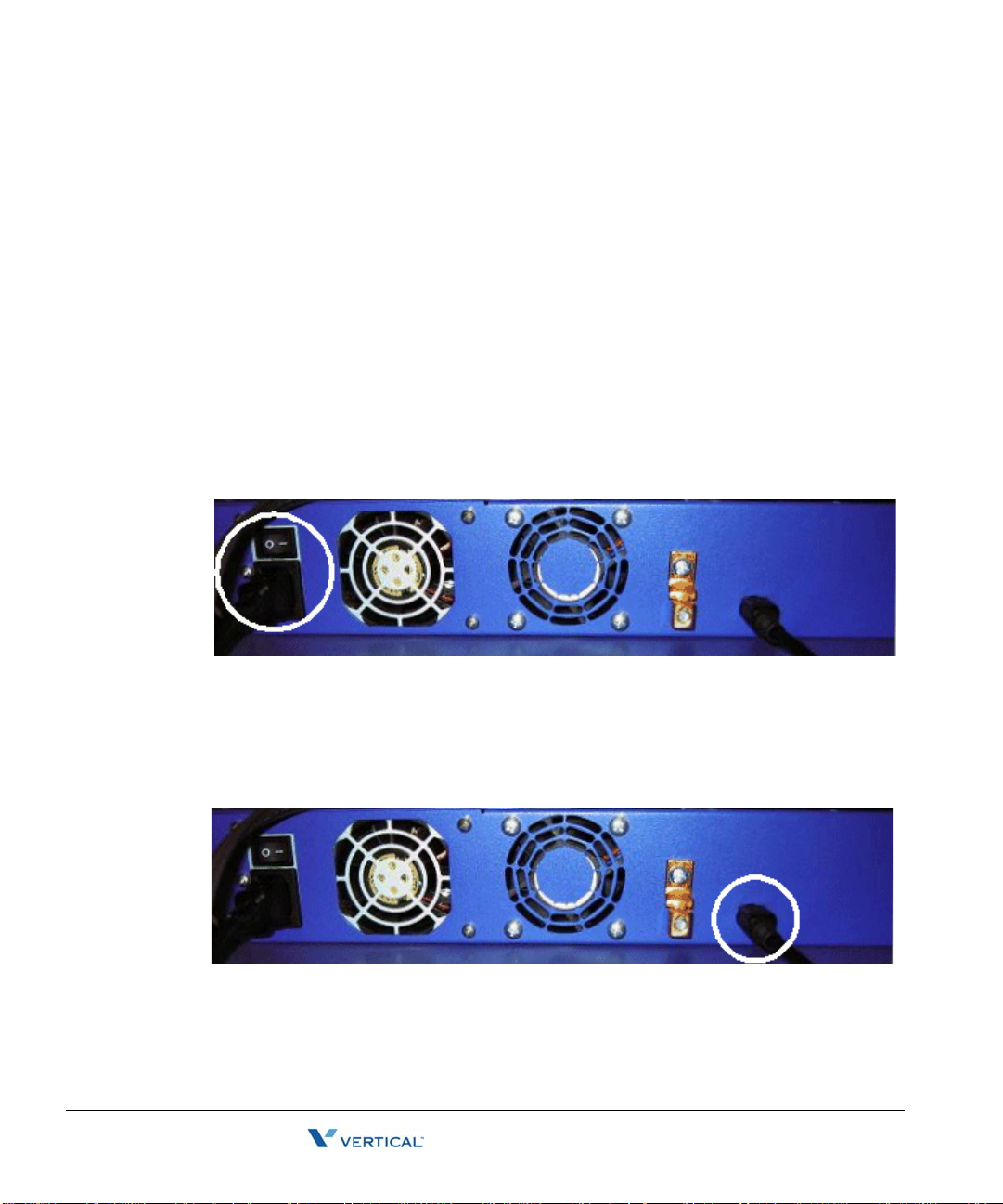
To connect the Wave Server to power and power on:
1. Locate the power outlet and power toggle switch on the back of the Wave Server.
2. Set the power supply rocker switch to the off position.
3. Connect the power cable to a dedicated circuit.
4. If you are using an external power supply to support digital phones, locate the connector
to the right of the ground lug.
Wave Server Installation Guide

Connecting the Wave Server to your LAN 3-11
Release 2.0 Service Pack 1
April 2011
Chapter 3: Setting Up the Wave IP 500 Server
5. Connect the external power supply cable to the connector, and then connect the cable to
power.
6. Power on the Wave Server by toggling the rocker switch, and then press the red button on
the front of the W ave Ser ver.
7. Observe the status LEDs on the fron t of the Wave Server chassis to ensure that the system
initialization completes successfully and that there are no component failures.
For complete details of the information provided by the status LEDs, see Appendix C,
“Integrated Services Card Status LEDs.”
Connecting the Wave Server to your LAN
This section describes how to connect the Wave Server to your LAN using a standard Ethernet
cable.
Note: The cabling for your LAN should be installed by a network cabli ng pro fession al before
the arrival of the Wave Server.
To connect the Wave Server to your LAN:
1. Locate the 8-pin modular RJ-45 Ethernet port labeled ENET on the front of the ISC2.
2. Connect one end of a standard, straight-through Ethernet cable to the ENET port.
3. Connect the other end of the cable to your LAN’s hub or data switch.
Wave Server Installation Guide

Connecting to trunk and station ports on the ISC2 3-12
Release 2.0 Service Pack 1
April 2011
Chapter 3: Setting Up the Wave IP 500 Server
Connecting to trunk and station ports on the ISC2
The RJ-11 ports on the ISC2 provide the following:
• 2 analog FXO trunk ports that support loop start trunks only.
• 2 analog FX S station ports.
See Appendix B, ”Trunk and Station Ports and Pinouts” for RJ-11 interface port descriptions
and pinout pairs for the ISC2.
To connect to analog trunk and station ports on the ISC2:
1. Locate the RJ-11 ports (labeled Trunk 1-2 and SLT 1-2) on the ISC2.
Power failover support
2. Using standard phone cables, connect station and trunk ports directly to phone or wall
jacks or a patch panel.
W ave provides failover telephone s ervice (power failure lifeline) in the event o f a power failure.
If the power fails, the analog phone connected to the SLT 1 port on the ISC2 automatically
connects to the analog trunk plugged into the T run k 1 p ort, enabling th at analog p hone to make
calls even if the Wave Server is not functioning.
When using that analog phone during a power fa ilure, you do not need to d ial an outside access
digit (for example 9) to place an outside call.
Hint: When setting up your telephones, locate the analog telephone connected to the SLT 1 port
in a convenient area, such as the lobby or front des k, so that it is easily accessible du ring a power
failure.
Wave Server Installation Guide

Installing expansion components 3-13
Release 2.0 Service Pack 1
April 2011
Chapter 3: Setting Up the Wave IP 500 Server
Installing expansion components
This section describes how to install the following components to expand the Wave IP 500:
• Media Resource Module (MRM). See the next section.
• Expansion modules. See page 3-13.
For technical specifications for these ex pansion components, see the Wave Hardware Refer ence
Guide.
Installing a Media Resource Module
Only one MRM (an MRMA) can be installed on the ISC2.
Important: Your W ave Server may come with an MRM, or you can order an d install an MRM
at a later time. If you do add an MRM at a later time, be sur e to review the n ote on page 7-5 for
important information about updating default IP network settings for the new MRM.
To install an MRM:
1. Unplug the Wave Server’s power cord, but do not disconnect the grounding wire.
2. Remove the t op cover.
3. Align the MRM over the standoffs, and then fast en the 4 retenti on screws in the corner
holes.
4. Plug the MRM ribbon connector into connector P2 (the light-blue 40-pin socket) on the
ISC2.
5. Replace the top cover and reattach it with the original screws.
6. Reconnect the Wave Server to power.
Installing expansion modules
This section provides guidel ines for installing all modu les. See “About connecting mod ules” on
page 3-15 for information on connectin g trunks, station s, and oth er devi ces to spe cific mod ules
after you have installed them.
Caution: The Wave Server’s analog station interface is not designed to withstand surges
commonly associated with wires that are exposed to the external environment. Do not route the
wires connecting analog station modules to stations outside the building where the W ave Server
is located.
Note: Because the required steps are different, installing a Media Resource Module is covered
separately on page 3-13.
Wave Server Installation Guide

Installing expansion components 3-14
Release 2.0 Service Pack 1
April 2011
Chapter 3: Setting Up the Wave IP 500 Server
To install modules:
1. Unplug the Wave Server’s power cord, but do not disconnect the grounding wire.
2. Remove the plastic bezel that covers the front of the Wave IP 500. To do so, grasp the
tabs of the bezel on both sides and pull forward.
3. Remove the blank module faceplate.
4. Insert modules and cards carefully.
5. Seat the module properly for good electrical connection. Engage the module by pressing
gently on it—be sure to press on the faceplate, not a connector or component on the
module.
6. Install blank faceplates on all unused slots.
7. Reconnect the Wave Server to power.
Module status LEDs
Each module has a pair of LEDs that indicate the component’s status:
Status Red LED Green LED
System is in an early boot phase. off off
System boot is in progress, or a firmware flash
update is in progress.
System is operational with no errors. off Blinking green
System shutdown is in progress. Blinking red Blinking green
Error condition exists on the syst em. Red off
System upgrade is in progress. Blinking red Green
Hard drive imaging in progress (via th e Wave
System Recovery Disk.)
T1/E1 module alarm indicators
Blinking red off
Red Green
The T1 module with serial interface and E1 EuroISDN module with serial interface have
additional alarm indicators, one set for the T1/E1 port and one set for the serial port, located to
the left of the module status LEDs. See “Alarm indicators ” in Chapter 15 in the W ave Hardware
Reference Guide for more information.
Wave Server Installation Guide

About connecting modules 3-15
Release 2.0 Service Pack 1
April 2011
Chapter 3: Setting Up the Wave IP 500 Server
About connecting modules
This section provides general information about connecting trunks, stations, and other devices
to modules. Instructions for connecting specific modules are described in subsequent sections.
Important: Before conne cting modules, ensu re that the f ollowing tasks have been completed,
depending on your configuration:
• The punchdown block or patch panel has been properly wired.
• Analog and T1 trunks have been installed by your service provider.
• I ncom ing an alog DID trunks have been tested to ensure no voltage is pr esent, as well as
to verify that they are DID trunks.
About cable connections
Modules and cards use standard cable connectors and jacks, as listed in the following table:
Module RJ-11 RJ-21X RJ-45 RJ-48C 3.5 mm
audio
Integrated Services
Card (ISC2)
Analog trunk module
Analog universal
module
Digital station module
T1 module with serial
interface
T1 module (without
serial interface)
E1 EuroISDN module
with serial inte rface
Quad BRI module
41 23
1
1
1
1
1
1
4
USB
Note: Some modular connectors look alike. Verify that your cables use the stan dard connectors
specified for a particular module.
Wave Server Installation Guide

About connecting modules 3-16
Release 2.0 Service Pack 1
April 2011
Chapter 3: Setting Up the Wave IP 500 Server
Connecting an RJ-21X cable
Important: In order to ensure a secure fit when connecting an RJ-21X (25-pair amphenol)
cable to a station or trunk module, you should use 3/4-inch 4-40 captive (partially threaded) pan
head screws. Be aware that some RJ-21X cables may come with screws that are too short, and
you should replace them with 3/4-inch screws.
To connect an RJ-21X cable to a module:
1. Connect the cable(s) to the connector(s). There are 2 kinds of RJ-21X cables:
180° cable—The cable comes straight out the back of the connector.
•
You can connect a 180° cable using the bale clips on the module to connect to a slot
on the cable housing, or using screws.
Wave Server Installation Guide

About connecting modules 3-17
Release 2.0 Service Pack 1
April 2011
Chapter 3: Setting Up the Wave IP 500 Server
• 90° cable—The cable comes out of the side of the connector and then makes a 90°
turn.
You can connect a 90° cable on only one side using a screw . On the other s ide, use a
tie down on the module or card to secure the cable to the board with a tie wrap.
2. Make sure that the cables are securely connected. The tabs on modular connectors click
in when the cables are secure. Secure the cable to an RJ-21X connector with the cable
strap.
About connecting specific modules
See the following sections for information about connecting each of the supported modules:
• Analog trunk module. See page 3-18.
• Analog universal module. See page 3-18.
• D igital station module. See page 3-19.
• T1 module with serial interface. See page 3-20.
• E1 module with serial interface. See page page 3-22.
• Quad BRI module. See page 3-23.
Caution: Ensure that only analog phones are connected to analog station ports and only digital
phones to digital station ports. This will prevent damage to the analog circuitry.
Wave Server Installation Guide

Connecting the analog trunk mo dul e 3-18
Release 2.0 Service Pack 1
April 2011
Chapter 3: Setting Up the Wave IP 500 Server
Connecting the analog trunk module
The analog trunk module provides 8 analog FXO loop start or ground start trunk ports. It is a
partial-width module that can be installed in any module slot.
See Appendix B, ”Trunk and S tation Ports and Pinou ts” for RJ-21X interf ace port descriptions
and pinout pairs for the analog trunk module.
To connect the analog trunk module:
1. Locate the RJ-21X port on the module.
2. Connect the RJ-21X (25-pair amphenol) cable to the port. (See “Connecting an RJ-21X
cable” on page 3-16.)
3. The cable can then be punched down, most commonly to a patch panel port, but it can
also be punched down to a punchdown block where it is then cross-connected to the
station cabling or analog circuits.
Connecting the analog universal module
The analog universal module provides the following:
• 8 analog FXO trunk ports, supporting loop start, ground start, and analog DID trunks
(analog DID trunks support inbound calling only).
• 8 analog FXS station ports.
The analog universal module is a partial-width module that can be installed in any module slot.
See Appendix B, ”Trunk and S tation Ports and Pinou ts” for RJ-21X interf ace port descriptions
and pinout pairs for the analog universal module.
To connect the analog universal module:
1. Locate the RJ-21X port on the module.
2. Connect the RJ-21X (25-pair amphenol) cable to the port. (See “Connecting an RJ-21X
cable” on page 3-16.)
3. The cable can then be punched down, most commonly to a patch panel port, but it can
also be punched down to a punchdown block where it is then cross-connected to the
station cabling or analog circuits.
Wave Server Installation Guide

Connecting the digital stati on module 3-19
Release 2.0 Service Pack 1
April 2011
Chapter 3: Setting Up the Wave IP 500 Server
Connecting the digital station module
Depending on the specific model, the digital station module provides 12 or 24 digital station
ports (see the W ave Har dwar e Refer ence Guide for details.) It is a partial-width module that can
be installed in any module slot.
See Appendix B for RJ-21X interface port descriptions and pinout pairs for the digital station
module.
To connect the digital station module:
1. Locate the RJ-21X port on the module.
2. Connect the RJ-21X cable from your punchdown block or patch panel to the port. (See
“Connecting an RJ-21X cable” on page 3-16.)
Connecting the external power supply for digital phones
Y ou must u se an external power supply to provide power to digi tal phones. See “External power
supply for digital phones” on page 3-6 for details.
To connect the external power supply:
1. Locate the power outlet on the back of the Wave IP 500.
2. Connect the power cord on the external power supply to the outlet.
Wave Server Installation Guide

Connecting the T1 module with serial interface 3-20
Release 2.0 Service Pack 1
April 2011
Chapter 3: Setting Up the Wave IP 500 Server
Connecting the T1 module with serial interface
Note: This section describes how to connect the T1 module with serial interface. For
information about installing the 1-port T1 module, see page 3-21.
The T1 module with serial interface and built-in CSU/DSU supports one T1 or ISDN PRI digital
trunk to provide shared data and voice services over a single T1 circuit.
There are 3 connectors on the T1 module:
• The RJ-48C port is used to connect to the T1 or ISDN PRI network interface.
• The DB-60 port provides V.35 serial communications for data connections, for example
to connect to the DB-60 cable from an external router.
• The bantam jack located to the right of the RJ-48C port accepts a 3-conductor Bantam
cable. It is provided for diagnostic purposes and is to be used only by an authorized
technician.
The T1 module is a partial-width module that can be installed in any module slot.
See the note on page 3-14 for information about alarm indicators specific to this module.
To connect the T1 module with serial interface:
1. Locate the RJ-48C port and DB-60 connector on the module.
2. Connect the T1 cable to the RJ-48C port.
3. Connect the serial cable from your external router to the DB-60 port.
The serial cable may be either a DB-60 male to DB-60 male cable, or a DB-60 male to
V.35 female DCE cable. In either case the DB-60 male connector goes to the DB-60
female port on the ISC2.
Caution: Use care when connecting or disconnecting the serial cable. Because of the
connector’s small size and high pin count, pins on the cable connector can be easily bent
and the DB-60 port may be damaged.
Wave Server Installation Guide

Connecting the T1 module (without serial interface) 3-21
Release 2.0 Service Pack 1
April 2011
Chapter 3: Setting Up the Wave IP 500 Server
Connecting the T1 module (without serial interface)
Note: This section describes how to connect the 1-port T1/PRI modu le without serial interface.
For information about installing the 1-port T1 module with serial interface, see page 3-20.
The T1 module supports one T1 or ISDN PRI digital trunk.
There are 2 connectors on the T1 module:
• The RJ-48C port is used to connect to the T1 or ISDN PRI network interface.
• The bantam jack located to the right of the RJ-48C port accepts a 3-conductor Bantam
cable. It is provided for diagnostic purposes and is to be used only by an authorized
technician.
The T1 module is a partial-width module that can be installe d in any module slot . This modu le
has one alarm indicator for the T1 port. See “Alarm indicators” in Chapter 15 in the Wave
Hardware Reference Guide for more information.
To connect the T1 module:
1. Locate the RJ-48C port on the module.
2. Connect the T1 cable to the RJ-48C port.
Wave Server Installation Guide

Connecting the E1 EuroISDN module with serial interface 3-22
Release 2.0 Service Pack 1
April 2011
Chapter 3: Setting Up the Wave IP 500 Server
Connecting the E1 EuroISDN module with serial interface
The E1 EuroISDN module with serial interface and built-in CSU/DSU supports one E1 ISDN
digital trunk to provide shared data and voice services over a single E1 circuit.
There are 3 connectors on the E1 EuroISDN module:
• The RJ-48C port is used to connect to the E1 ISDN network interface.
• The DB-60 port provides V.35 serial communications for data connections, for example
to connect to the DB-60 cable from an external router.
• The bantam jack located to the right of the RJ-48C port accepts a 3-conductor Bantam
cable. It is provided for diagnostic purposes and is to be used only by an authorized
technician.
The E1 EuroISDN module is a partial-width module that can be installed in any module slot.
See the note on page 3-14 for information about alarm indicators specific to this module.
To connect the E1 EuroISDN module:
1. Locate the RJ-48C port and DB-60 connector on the module.
2. Connect the E1 cable to the RJ-48C port.
3. Connect the serial cable from your external router to the DB-60 port.
The serial cable may be either a DB-60 male to DB-60 male cable, or a DB-60 male to
V.35 female DCE cable. In either case the DB-60 male connector goes to the DB-60
female port on the ISC1ISC2.
Caution: Use care when connecting or disconnecting the serial cable. Because of the
connector’s small size and high pin count, pins on the cable connector can be easily bent
and the DB-60 port may be damaged.
Wave Server Installation Guide

Connecting the Quad BRI module 3-23
Release 2.0 Service Pack 1
April 2011
Chapter 3: Setting Up the Wave IP 500 Server
Connecting the Quad BRI module
The Quad BRI Module supports ISDN Basic Rate Interface (BRI) digital trunks, and provides
connectivity between the Wave Server and Central Office (CO) equipment supporting
Euro-ISDN BRI com municatio n prot ocols. The Quad BRI Mod ule sup ports 4 Eu ro-ISD N BRI
trunks and up to 8 simultaneous voice calls.
There are 4 RJ-45 connectors on the Quad BRI module.
The Quad BRI module is a partial-width module that can be installed in any module slot or in
any universal slot via a module converter.
To connect the Quad BRI module:
1. Locate the RJ-45 ports on the module.
2. Connect each port to a Euro-ISDN BRI trunk cable.
Connecting a music-on-hold (MOH) system
A music-on-hold device plays prerecorded mus ic or messages to callers—either fro m a tape or
CD—when they are placed on hold or while being transferred.
The W ave Server is compatible with most standard music-on- hold devices that connect via a 3.5
mm stereo plug. If a cable is not provided, you must purchase one separately.
Note: Although a stereo cable is required, music on hold only plays in mono.
Caution: Always follow the instructions supplied by the manufacturer of your music-on-hold
device when installing and connecting the dev ice to avoid po ssible injury to yourself or damage
to the equipment.
Wave Server Installation Guide

Connecting a paging system 3-24
Release 2.0 Service Pack 1
April 2011
Chapter 3: Setting Up the Wave IP 500 Server
To connect a music-on-hold device:
1. Locate the audio input port (labeled Audio In) on the ISC2.
2. Connect the cable from your music-on-hold device to the port.
3. Enable music on hold in the General Settings applet of the Global Administrator
Management Console. See the Wave Global Administrator Guide for more information.
Connecting a paging system
A paging system allows Wave users to make public announcements over a loudspeaker.
The Wave Server is compatible with most standard paging systems that connect via a 3.5 mm
stereo plug. If a cable is not provided, you must purchase one separately.
Note: Although a stereo cable is required, only one channel is used for paging.
Caution: Always follow the instructi ons supplied by the manufactu rer of your paging system
when installing and connecting the system to avoid possible injury to yourself or damage to the
equipment.
Wave Server Installation Guide

Connecting a DSS Console 3-25
Release 2.0 Service Pack 1
April 2011
Chapter 3: Setting Up the Wave IP 500 Server
To connect a paging system:
1. Locate the audio output port (labeled Audio Out) on the front of the ISC2.
2. Connect the cable from your paging system to the port.
3. Enable paging in the General Settings applet of the Global Administrator Management
Console. See the Wave Global Administrator Guide for more information.
Connecting a DSS Console
The Edge 700 Direct Station Selection (DSS) 48-Button Console expands a receptionist’s
digital phone with 48 additional flexible buttons with LEDs to connect to system endpoints such
as user extensions. Up to 5 DSS Consoles can be associated with a single digital phone,
providing up to 240 additional buttons.
Wave Server Installation Guide

Connecting a DSS Console 3-26
Release 2.0 Service Pack 1
April 2011
Chapter 3: Setting Up the Wave IP 500 Server
The DSS Console co nnects to a digita l station port on any of the f ollowing modules on the W av e
IP 500:
• 12-Port Digital Station Module (VW5-12DS2-M)
• 24- Port Digital Station Module (VWU-24DS2-M)
For instructions on how to configure a DSS Console for a user, see “The Phone \ DSS Consoles
tab” in Chapter 10 in the Wave Global Administrator Guide.
To connect a DSS Console:
1. Locate an unused port on the digital station module.
2. Connect the DSS Console to the digital station port using an RJ-11 cable. The maximum
cable length between the Wave Server and the DSS Console is 1968 feet (600 m).
Note: There is no physical connection between the DSS Console and the user’s digital
phone.
Wave Server Installation Guide

Chapter 4
Release 2.0 Service Pack 1
April 2011
Setting Up the Wave IP 2500 Server
CHAPTER CONTENTS
About the Wave IP 2500 Server. . . . . . . . . . . . . . . . . . . . . . . . . . . . . . . . . . . . . 4-2
Mounting the Wave Server. . . . . . . . . . . . . . . . . . . . . . . . . . . . . . . . . . . . . . . . . 4-7
Grounding the Wave Server. . . . . . . . . . . . . . . . . . . . . . . . . . . . . . . . . . . . . . . 4-12
Connecting the Wave Server to power and powering on. . . . . . . . . . . . . . . . . 4-13
Connecting the Wave Server to your LAN . . . . . . . . . . . . . . . . . . . . . . . . . . . . 4-14
Connecting to trunk and station ports on the ISC1. . . . . . . . . . . . . . . . . . . . . . 4-15
Installing expansion components. . . . . . . . . . . . . . . . . . . . . . . . . . . . . . . . . . . 4-16
About connecting modules and cards . . . . . . . . . . . . . . . . . . . . . . . . . . . . . . . 4-21
Connecting the analog trunk module . . . . . . . . . . . . . . . . . . . . . . . . . . . . . . . . 4-24
Connecting the analog universal module. . . . . . . . . . . . . . . . . . . . . . . . . . . . . 4-25
Connecting the digital station module . . . . . . . . . . . . . . . . . . . . . . . . . . . . . . . 4-25
Connecting the T1 module with serial interface. . . . . . . . . . . . . . . . . . . . . . . . 4-26
Connecting the T1 module (without serial interface) . . . . . . . . . . . . . . . . . . . . 4-27
Connecting the E1 EuroISDN module with serial interface . . . . . . . . . . . . . . . 4-27
Connecting the Quad BRI module . . . . . . . . . . . . . . . . . . . . . . . . . . . . . . . . . . 4-28
Connecting the digital station card. . . . . . . . . . . . . . . . . . . . . . . . . . . . . . . . . . 4-29
Connecting a music-on-hold (MOH) system . . . . . . . . . . . . . . . . . . . . . . . . . . 4-30
Connecting a paging system . . . . . . . . . . . . . . . . . . . . . . . . . . . . . . . . . . . . . . 4-31
Connecting a DSS Console . . . . . . . . . . . . . . . . . . . . . . . . . . . . . . . . . . . . . . . 4-32
Important: This chapter app lies to you if you are installing a Wave IP 2500 Server. If you are
installing a Wave IP 500 Server, go to Chapter 3.
Wave Server Installation Guide

About the Wave IP 2500 Server 4-2
Release 2.0 Service Pack 1
April 2011
Chapter 4: Setting Up the Wave IP 2500 Server
About the Wave IP 2500 Server
The Wave IP 2500 Server consists of the following components.
• Wave Server base unit. See the next section.
• Power supply. See page 4-4.
• Expansion options, including expansion cards and modules, Expansion Units (EXUs),
and the Media Resource Modules (MRMs). See page 4-5.
Important: Note that a monitor, keyboard, and mouse are not included with and are not
supported on the Wave Server. You use the administrator PC, described in Chapter 5, to
configure and manage the Wave ISM.
About the Wave IP 2500 base unit
The Wave IP 2500 base unit consists of the following:
• A 19-inch rack-mountable chassis that includes room for expansion.
• The Wave Integrated Services Card (ISC1), an embedded processor that provides primary
system control including voice processing and packet switching elements.
About the ISC1
The ISC1 includes the following:
• 6 SIP Gateway ports
• 4 analog FXO trunk ports (first four pairs on a shared RJ-21X connector)
• 4 analog FXS station ports (last four pairs on a shared RJ-21X connector)
Wave Server Installation Guide

About the Wave IP 2500 Server 4-3
Release 2.0 Service Pack 1
April 2011
Chapter 4: Setting Up the Wave IP 2500 Server
• 2 10/100 Mbps Ethernet ports (ports are mirro red and are n ot separatel y addressabl e). See
“About the Ethernet ports on the Wave Server” on page 4-14 for important information
about using these ports.
• 2 partial-width slots that can accommodate 2 expansion modules
• 2 full-width universal slots that can accommodate 2 expansion cards or modules
• 1 USB device port
•1 USB host port
• RJ-21X connector (with embedded FXS and FXO ports)
• Audio port for an external music-on-hold source
• 1 port for an external paging system
• V.34 Fax modem
• Status LEDs (described in detail in Ap pendi x C)
The following diagram illustrates the system ports, LEDs, and buttons on the front of the ISC1:2
Wave Server Installation Guide

About the Wave IP 2500 Server 4-4
Release 2.0 Service Pack 1
April 2011
Chapter 4: Setting Up the Wave IP 2500 Server
Power supply
The Wave IP 2500 Server is equipped with one power supply.
If a power failure occurs, an optional Uninterruptable Power Supply (UPS) can provide several
minutes of system power, allowing a technician to properly shut down the Wave Server. Wave
can also integrate with 3rd-party UPS software to provide graceful shutdown of the s ys tem v ia
network or U S B signalling.
A UPS is not provided by Vertical, but can be purchased from a third-party source. For
information about recommended UPS specifications, refer to Appendix C in the Wave Server
Hardware Reference Guide.
Minimum configuration
The ISC1 is the minimum requirement for a Wave IP 2500 system. Expansion modules and
cards are available to expand the Wave IP 2500 Server base unit to support a wide variety of
trunk and station configuration s.
Redundancy
The W ave IP 2500 Server chassi s has been designed to support redundant hard drives. All Wave
IP 2500 Servers ship with redundant hard drives as part of the standard configuration.
In case of a primary (master) har d drive failure, yo u can use th e redund ant (slave) har d drive to
run the Wave IP 2500 Server chassis.
Fault monitoring
A proprietary Fault Monitor Module is an integral part of the embedded firmware running on
the ISC1, and receives system error-trace messages and stor es them in memory. As soon as the
Wave Server is powered on, the Fault Monitor Module starts monitoring the status of the
Microsoft Windows Server operating system, the power supply status, the ISC1temperature,
and the Power-on/Shut down button. You can configure the Fault Monitor Modu le to dial a pager
number that notifies the system administrator of system errors.
For more information, see Appendix A, “Fault Monitor Module and Trace Log” in the Wave
Server Hardware Reference Guide.
To configure the Fault Monitor Module, see the Wave Global Administrator Guide.
Wave Server Installation Guide

About the Wave IP 2500 Server 4-5
Release 2.0 Service Pack 1
April 2011
Chapter 4: Setting Up the Wave IP 2500 Server
Wave IP 2500 expansion options
The ISC1 is the minimum requirement for a Wave IP 2500 system.
There are several ways to expand the Wave Server base unit to handle additional users and
increased traffic, and support a wide variety of trunk and station configurations:
• Expansion cards and modules
• E xpan sion Units (EXUs)
• Media Resource Modules (MRMs)
For technical specifications for these expansion components, see the Wave Server Hardware
Reference Guide.
Expansion cards and modules
The Wave Server supports two kinds of expansion boards—modules and cards.
Modules are partial-width boards that can be installed in module slots in the base unit or
•
in Expansion Units (EXUs, described on page 4-6).
Modules can also be instal led in univ ersal card slot s in th e base unit or in EXU s usi ng the
IP 2500 Module Conversion Kit (VW-IP2500-CONV), a mechanical assembly which
attaches to a module.
The following modules are available:
Analog tru n k mo dul e . Supp ort s 8 anal og F X O l oop s t art or ground start trunk ports.
•
See page 4-24.
Analog universal module. Supports 8 analog FXS station ports and 8 analog FXO
•
loop start or ground start trunk ports. See page 4-25.
Digital station module. Depending on the specific model, supports 12 or 24 digital
•
station ports. See page 4-25.
T1 module with serial interface. Sup ports a singl e T1 (PRI or CAS signali ng) digital
•
trunk. It features an integrated CSU/DSU, and allows shared data and voice services
over a single T1 circuit. See page 4-26.
T1 module (without serial interface). Supports a single T1 (PRI or CAS signaling)
•
digital trunk. See page 4-27.
Wave Server Installation Guide

About the Wave IP 2500 Server 4-6
Release 2.0 Service Pack 1
April 2011
Chapter 4: Setting Up the Wave IP 2500 Server
• E1 EuroISDN module with serial inte rface. Supports a single E1 ISDN digita l trunk.
It features an integrated CSU/DSU, and allows shared data and voice services over
a single E1 circuit. See page 4-27.
Quad BRI module. Supports 4 Basic Rate Interface (BRI) digital trunks and up to 8
•
simultaneous voice calls, and provides connectivity between the Wave Server and
Central Office (CO) equipment supporting Euro-ISDN BRI communication
protocols. See page 4-28.
Cards are full-width boards that support more ports than modules do. Cards can be
•
installed in the universal card slots in the base unit or in EXUs.
The following cards are available:
•
Analog station card. Supports 24 analog FXS station ports. See page 4-29.
Digital stat ion c ard . Depend ing on the mod el, su pports 12 or 2 4 digital station ports.
•
See page 4-29.
For installation instructions, see page 4-20.
Expansion Units (EXUs)
An EXU provides 2 universal slots that can each suppo rt one module or card. Up to 4 modular
EXUs can be mounted on to p of t he Wave IP 2500 Server base unit. A fully ex panded Wave IP
2500 Server with 4 EXUs provides 8 additional universal slots.
For installation instructions, see page 4-17.
Media Resource Modules (MRMs)
Each W a ve ISM system is p re-configured to supp ort a specific number of users and co ncurrent
voice applications. To expand the system’s core telephony, voice processing, and VoIP
capabilities you can add a Media Resource Module. The MRM is a mezzanine-style daughter
board that is installed on the Integrated Services Card (ISC1).
You can install one MRM on the Wave IP 2500 Server.There are 3 available MRM models
(MRMA, MRMB, and MRMC) that pro vide up to 128 , 256, or 3 84 additional v oice processi ng
channels.
Note: At least one MRM is required if you plan to use Quality of Service (QoS) settings with
IP resources for VoIP calls. Contact your Wave provider for more information.
For installation instructions, see page 4-18.
Wave Server Installation Guide

Mounting th e Wave Server 4-7
Release 2.0 Service Pack 1
April 2011
Chapter 4: Setting Up the Wave IP 2500 Server
Mounting the Wave Server
The Wave IP 2500 Server can be rack mounted, wall mounted, or table mounted. See
“Environmental requirements” on page 2-4 for specific requirements on how to prepare site the
where the Wave Server will reside.
Caution: Due to the weight of the Wave Server, moun t it with assistance whenever po ssible.
Review “Proper lifting” on page 2-7 before rack mounting.
Important: Note the following:
• Do not place anything on or against the base unit that prevents proper ventilation. Be sure
to allow a minimum cooling clearance of 4 inches on all sides of the Wave Server.
• To prevent the fans from p ulling dus t in to the bas e u nit, mount the Wave Server at least 2
feet (0.5 meters) above the floor. Do not operate the Wave Server at floor level.
Rack mounting the Wave Server
The Wave IP 2500 Server is shipped ready to be rack mounted. The Wave Server requires an
EIA- or IEC-compliant, 19-inch rack for proper mounting. See “Physical specifications” on
page 2-4 for the dimensions of the Wave Server, including rack height.
To rack mount the Wave Server:
1. Insert a rack mounting screw loosely into each side of the rack.
2. Slide the Wave Server base unit into the rack and hang it onto the screws using either the
keyhole or slot on each mounting bracket. (This frees you from having to hold the base
unit in place as you continue.)
Wave Server Installation Guide

Mounting th e Wave Server 4-8
Release 2.0 Service Pack 1
April 2011
Chapter 4: Setting Up the Wave IP 2500 Server
3. Tighten the screws, and then insert and tighten a second rack mounting screw in each
bracket.
When successfully rack-mounted, the Wave Server base unit looks like this:
Wall mounting the Wave Server
You can mount the Wave IP 2500 Server base unit onto a wall by first attaching a piece of
prepared plywood to studs in the wall, then attaching the base unit to the plywood.
Note: You can only wall mount the Wave Server base unit itself —wall mounting is not an
option if you are using one or more EXUs.
Caution: Note the following:
• Do not attach the base unit directly to a wall without using the plywood as a support—the
plywood must be firmly attached to wall studs in order to support the weight of the base
unit.
• Do not wall mount the base unit so that the cards appear in a horizontal position. Only
wall mount the base unit so that the cards are in a vertical position, as shown in the
illustration on page 4-11.
Wave Server Installation Guide

Mounting th e Wave Server 4-9
Plywood
24"
34 “
(10.2 cm)
3 1/4"
(8.3 cm)
4”
Two lines
(61 cm)
(6.4 cm)
Release 2.0 Service Pack 1
April 2011
Chapter 4: Setting Up the Wave IP 2500 Server
To wall mount the Wave Server base unit:
1. Prepare a piece of plywood that meets the following minimum dimensions for proper
ventilation and service access:
Thickness—0.75 inches (2 cm)
Height—24 inches (61 cm)
Width— 34 inches (86.4 cm)
2. Draw a vertical line on the plywood 4 inches (10.2 cm) from the left edge, and a
horizontal line 3-1/4 in ches (8.3 cm) from the top edge:
3. Locate supporting studs in your wall, and firmly attach the prepared piece of plywood to
the studs using the appropriate screw s .
4. If the mounting brackets are currently installed on the front of the Wave Server, remove
them.
Wave Server Installation Guide
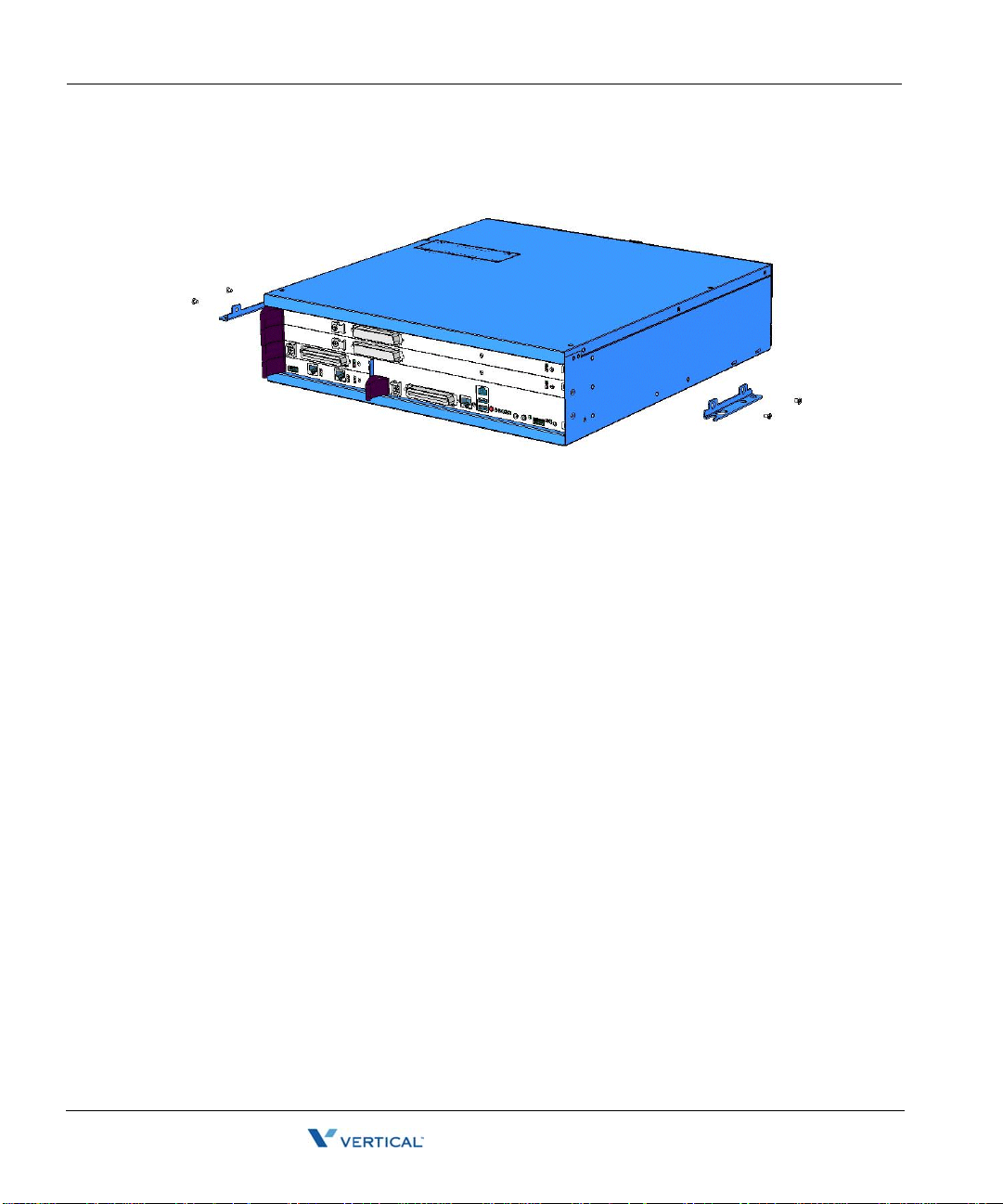
Mounting th e Wave Server 4-10
Release 2.0 Service Pack 1
April 2011
Chapter 4: Setting Up the Wave IP 2500 Server
5. Position the mounting brackets at the bottom of each of the base unit side panels. Use a
#2 Phillips screwdriver to fasten each mounting bracket to the base unit with the screws
provided.
6. With another person’s assistance, lift the Wave Server base unit and place it against the
wall-mounted plywood. Line up the left side of the base unit with the vertical line that
you drew on the plywood, and line up the top of the base unit with the horizontal line that
you drew.
Important: According to the directions in this step, the face plate will be facing to the
right (see the following illustration.) Y ou can rotate the base unit before attaching it to the
wall-mounted plywood so that the face plate faces to the left, in order to avoid power
outlets or other obstructions. However, the face plate cannot face up or down once the
base unit is mounted to the wall.
Wave Server Installation Guide
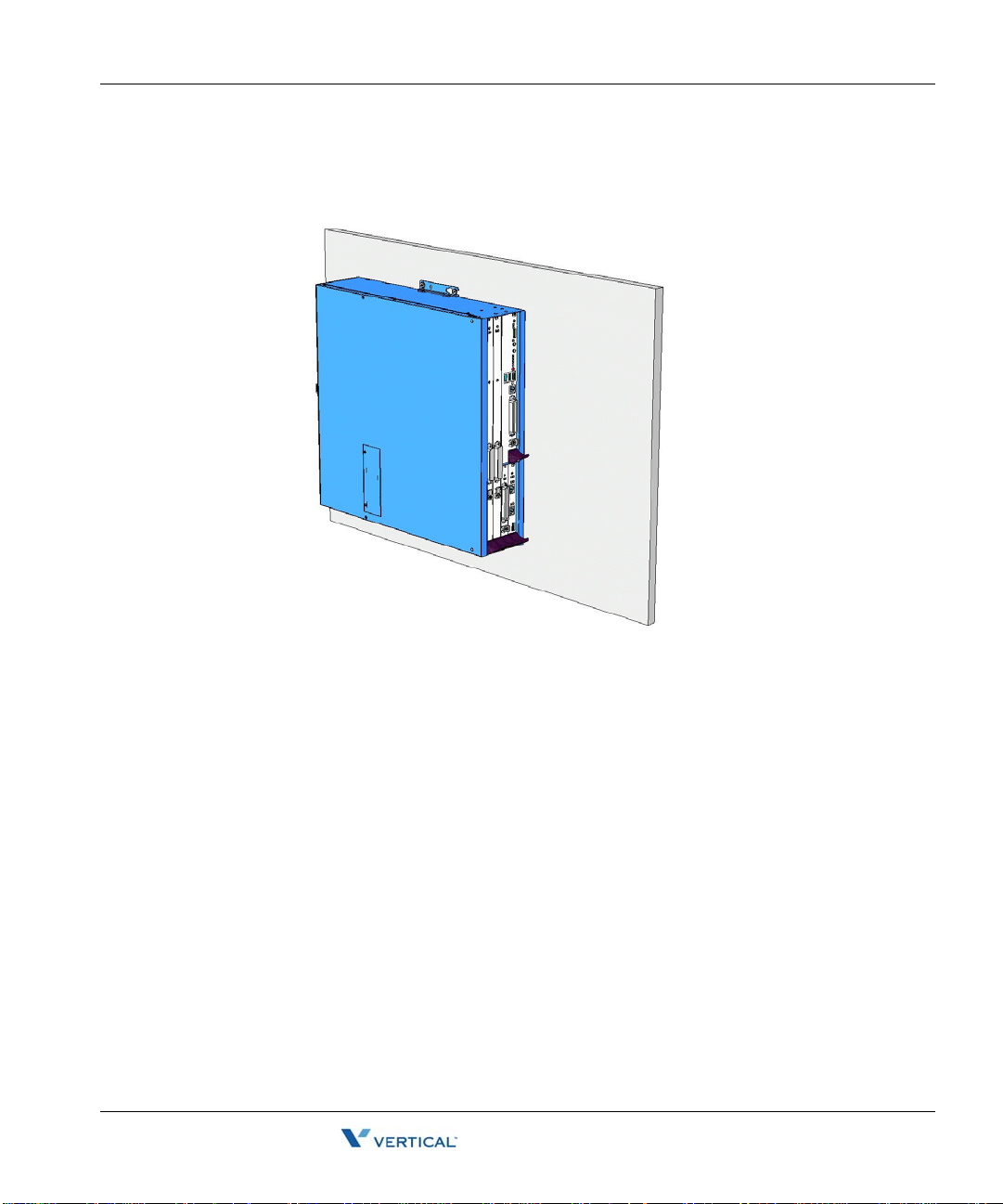
Mounting th e Wave Server 4-11
Release 2.0 Service Pack 1
April 2011
Chapter 4: Setting Up the Wave IP 2500 Server
7. Insert and tighten two self-threading #10 screws through each mounting bracket to
securely attach the base unit to the plywood. When s uccessfully wall-mo unted, the Wave
Server base unit looks like this:
Table mounting the Wave Server
T able mounting i s a convenient solution for tem porary or mobile operat ion requirements of the
Wave Server. Do not place the Wave Server on the floor.
Caution: Ensure that the table supports the w eight of your Wave Server including any EXUs.
See “Proper lifting” on page2-7 for system weight specifications.
Wave Server Installation Guide

Grounding the Wave Server 4-12
Release 2.0 Service Pack 1
April 2011
Chapter 4: Setting Up the Wave IP 2500 Server
Grounding the Wave Server
Warning: The pr otective ground lug (eart h contact) on the W ave Server base unit must
be permanently connected to earth.
Warning: The National Electrical Code requires that the telephone and electrical
services have a common ground. If separate gro unds are used for telephone a nd electrical
services, a voltage differential could develop between the two services. This could expose
you to an electrical shock and damage the equipment.
To ground the Wave Server:
1. Locate the ground lug on the back of the Wave Server base unit.
2. Loosen the slotted screw on the ground lug with a flat-head screwdriver.
3. Insert a 10- or 12-gauge stranded grounding wire into the ground lug opening.
4. Tighten the slotted screw.
5. Connect the other end of the grounding wire to one of the following ground types:
• Power service ground
• Bu ilding steel ground
• Metallic cold water pipe that is bonded to a power ground (if permitted by local
building codes)
• Ground rod that is 5 feet long and 5/8 inch in di ameter. (Use this option only if none
of the other options are available.)
Wave Server Installation Guide

Connecting the Wave Server to power and powering on 4-13
Release 2.0 Service Pack 1
April 2011
Chapter 4: Setting Up the Wave IP 2500 Server
Connecting the Wave Server to power and powering on
Connect the Wave IP 2500 Server to a dedicated circuit using the supplied power cord. Do not
use any othe r power cord.
Note: There are 2 power cord models, one for use in the US and one for International (EU) use.
See Appendix D in the Wave Server Hardware Reference Guide for voltage and current
specifications.
To connect the Wave Server to power and power on:
1. Locate the power outlet and power toggle switch on the back of the Wave Server base
unit.
2. Set the base unit po wer su pply rocker switc h and any EXU pow er swi tch rocker s witches
located on the back of the Wave Server base unit to the off position.
3. Connect the power cables from the base unit and any EXUs to dedicated circuits.
4. Set each EXU's rocker switch to the On position. (The EXU will not actually power on
until the base unit is powered on.)
5. Power on the base unit by toggling the rocker switch.
6. Observe the status LEDs on the front of the Wave Server base unit to ensure that the
system initialization completes successfully and that there are no component failures.
For complete details of the information provided by the status LEDs, see Appendix C,
“Integrated Services Card Status LEDs.”
Wave Server Installation Guide

Connecting the Wave Server to your LAN 4-14
Release 2.0 Service Pack 1
April 2011
Chapter 4: Setting Up the Wave IP 2500 Server
Connecting the Wave Server to your LAN
This section describes how to connect the Wave IP 2500 Server to your LAN using a standard
Ethernet cable.
Note: The cabling for your LAN should be installed by a network cabli ng pro fession al before
the arrival of the Wave Server.
About the Ethernet ports on the Wave Server
There are 2 Ethernet ports located on the front of the ISC1, labeled ENET 1 and ENET 2.
Important: ENET 1 and ENET 2 are con nected to an embedded switch in the ISC1 which does
not currently support the Spanning Tree algorithm. Consequently, ENET 1 a nd E NET 2 mu st
not both be simultaneously connected to another switch on your network. Connecting both
Ethernet ports to a switch on your network creates a loop that makes the embedded switch
inoperable, and the Wave Server will be cut off from your network.
• ENET 1 is the Wave Server’s primary interface and under nor mal conditions it is the only
interface that should be connected to your netwo rk. You use ENET 1 to connect the W a ve
Server to your network to make Wave ISM functionality available to a system
administrator on the network, for example access to the Global Administrator
Management Console, ViewPoint, VoIP station and trunk resources, and so forth.
• ENET 2 should only be used in the following special circumstances:
• To directly connect the administrator PC to the Wave Server, as described on
page 5-5. (You can also conn ect to the Wave Server from the administrator PC via a
local or remote modem connection, as described on page 5-8.)
• As a backup in case ENET 1 is not functional. You can use ENET 2 to connect the
Wave Server to your network, as long as ENET 1 is not used for the same purpose.
• For troubleshooting or diagnostic purposes, for example internal packet sniffing.
All packets exchanged between the Vertical Application Module (VAM) and the
embedded processor are copied to ENET 2 for diagnostic purposes. (Note that
packet copying does not significantly add to network traffic.)
Wave Server Installation Guide

Connecting to trunk and station ports on the ISC1 4-15
Release 2.0 Service Pack 1
April 2011
Chapter 4: Setting Up the Wave IP 2500 Server
To connect the Wave Server to your LAN:
1. Locate the 8-pin modular RJ-45 Ethernet port labeled ENET 1 on the ISC1.
2. Connect one end of a standard, straight-through Ethernet cable to the ENET 1 port.
3. Connect the other end of the cable to your LAN’s hub or data switch.
Connecting to trunk and station ports on the ISC1
The RJ-21X port on the ISC1 provides the following:
• 4 analog FXO trunk ports that support loop start trunks only.
• 4 analog FX S station ports.
See Appendix B, ”Trunk and S tation Ports and Pinou ts” for RJ-21X interf ace port descriptions
and pinout pairs for the ISC1.
To connect to analog trunk and station ports on the ISC1:
1. Locate the RJ-21X port (labeled J1) on the ISC1.
Wave Server Installation Guide

Installing expansion components 4-16
Release 2.0 Service Pack 1
April 2011
Chapter 4: Setting Up the Wave IP 2500 Server
2. Connect the 25-pair male amphenol cable to the RJ-21X port. The amphenol cable is then
punched down, most co mmo nl y t o a pat ch panel port, but it can al so be punched down to
a punchdown block where it is then cross-connected to the station cabling or analog
circuits.
Power failover support
W ave provides failover telephone s ervice (power failure lifeline) in the event o f a power failure.
If the power fails, the analog phone connected to Station Port 1 on the ISC1 automatically
connects to the analog trunk plugged into Trunk Port 1, enab ling that analog phone to make calls
even if the Wave Server is not functioning.
When using that analog phone during a power fa ilure, you do not need to d ial an outside access
digit (for example 9) to place an outside call.
Hint: When setting up your telephones, locate the analog telephone connected to Station Port
1 in a convenient area, such as the lobby or front desk, so that it is easily accessible during a
power failure.
Installing expansion components
This section describes how to install the following components to expand the Wave IP 2500
base unit:
• Expansion Unit (EXU). See the next section.
• Media Resource Module (MRM). See page 4-18.
• Expansion cards and modules. See page 4-20.
For technical specifications for these expansion components, see the Wave Server Hardware
Reference Guide.
Wave Server Installation Guide

Installing expansion components 4-17
Release 2.0 Service Pack 1
April 2011
Chapter 4: Setting Up the Wave IP 2500 Server
Installing EXUs on a Wave Server
You can install up to 4 EXUs on a Wave Server. EXU’s cannot be wall-mounted.
To install an EXU:
1. Unplug the Wave Server’s power cord, but do not disconnect the grounding wire.
2. Remove the connector hatch retention screws on the top of the Wave Server base unit,
and then remove the connector hatch.
3. Remove the backplane terminator from the base unit using both hands to pull it straight
up and out.
Caution: Make a note of the direction that th e ba ckplane termin ator is facing when y ou
remove so that you can replace it the same way . A reversed b ackplane terminator can cause
malfunctions and damage equipment.
4. Open the side and rear latches on the EXU.
5. Stack the EXU on top of the base unit or another EXU, aligning pins and electrical
connectors on the bottom of the EXU with the pins on the lower unit.
6. Press down gently to engage the backplane connector.
7. Engage the side and rear latches to secure the EXU.
Wave Server Installation Guide

Installing expansion components 4-18
Release 2.0 Service Pack 1
April 2011
Chapter 4: Setting Up the Wave IP 2500 Server
8. If the Wave Server base unit is rack-mounted, attach the EXU using 2 rack screws per
side. If this is the top-most EXU, go to step 10.
9. To install another EXU, remove the connector hatch from the top of the EXU that you
just installed. Repeat steps 4-8 to stack up to 4 EXUs.
10. Secure the backplane terminator to the topmost EXU.
Caution: Be sure to replace the backplane terminator facing the same direction it was
when you removed it. Also, p ay careful attention to pi n alignment. Connecto r pin A1 must
align with slot pin A1. DO NOT power on the Wave Server until you are certain that the
backplane terminator is installed correctly.
11. Replace the connector hatch on the topmost EXU and secure it with the retention screws.
12. Connect each EXU to power and ground it.
13. Reconnect the Wave Server to power.
A Wave Server base unit with 1 EXU is shown below.
Installing a Media Resource Module
Only one MRM can be installed on the ISC1.
Important: Your W ave Server may come with an MRM, or you can order an d install an MRM
(or upgrade to a different MRM model) at a later time. If you do add or upgrade an MRM at a
later time, be sure to review the note on page 7-5 for important information about updating
default IP network settings for the new MRM.
Wave Server Installation Guide

Installing expansion components 4-19
Release 2.0 Service Pack 1
April 2011
Chapter 4: Setting Up the Wave IP 2500 Server
To install an MRM:
1. Unplug the Wave Server base unit’s power cord, but do not disconnect the grounding
wire.
2. Remove the ISC1 from the Wave Server base unit. To do so:
• Label or note the position of any cables connected to the ISC1 faceplate.
• Disconnect all cables from the faceplate.
• Loosen the retention screws.
• Open the insertion lever at the left side of the faceplate, then pull firmly on the lever
to disengage the ISC1 from its slot.
3. Place the ISC1 on a static-safe work area.
4. Install the MRM standoffs on the ISC with the screws provided.
5. Align the MRM over the standoffs, and then fast en the 4 retenti on screws in the corner
holes.
6. Plug the MRM ribbon connector into connector P4 (the light-blue 40-pin socket) on the
ISC1.
7. Re-install the ISC1 in the Wave Server base unit. To do so:
• Slid e the ISC1 back into its slot.
• Engage the insertion lever.
• Fasten the retention screws.
• Reconnect cables to the faceplate.
8. Reconnect the Wave Server to power.
Wave Server Installation Guide

Installing expansion components 4-20
Release 2.0 Service Pack 1
April 2011
Chapter 4: Setting Up the Wave IP 2500 Server
Installing expansion modules and cards
This section provides guidelines for installing all modules and cards. See “About connecting
modules and cards” on page 4-21 for information on connecting trunks, stations, and other
devices to specific modules and cards after you have installed them.
Caution: The Wave Server’s analog station interface is not designed to withstand surges
commonly associated with wires that are exposed to the external environment. Do not route the
wires connecting analog station cards or modules to stations outside the building where the
Wave Server is located.
Note: Because the required steps are different, installing a Media Resource Module is covered
separately on page 4-18.
To install modules and cards:
1. Unplug the Wave Server base unit’ s po we r cord and th e power cord s of al l EXUs, but do
not disconnect the grounding wires.
2. Remove the blank module or universal slot faceplate.
3. Insert modules and cards carefully.
• Note the position of the circuit board installation guides—there are 2 guides per
slot:
• Modules align with the bottom guide.
• Cards align with the top guide.
• Note the position of slot connectors:
• The ISC1 slot and module slots have a single slot connector.
• Universal slots have 2 slot connectors.
• Modules connect to the bottom slot connector.
• Cards connect to the top slot connector
4. Seat the module or card properly for good electrical connection. Engage the black
insertion lever, and tighten all faceplate mounting screws.
5. To install a partial-width module in a full-width universal slot, use a Wave IP 2500
module converter. First, screw the module into the converter, and then insert the
converter into the universal slot.
6. Install blank faceplates on all unused slots.
7. Reconnect the Wave Server base unit and all EXUs to power.
Wave Server Installation Guide

About connecting modules and cards 4-21
Release 2.0 Service Pack 1
April 2011
Chapter 4: Setting Up the Wave IP 2500 Server
Module and card status LEDs
Each module and card has a pair of LEDs that indicate the component’s status:
Status Red LED Green LED
System is in an early boot phase. off off
System boot is in progress, or a firmware flash
update is in progress.
System is operational with no errors. off Blinking green
System shutdown is in progress. Blinking red Blinking green
Error condition exists on the system. Red off
System upgrade is in progress. Blinking red Green
Hard drive imaging in progress (via th e Wave
System Recovery Disk.)
T1/E1 module alarm indicators
The T1 module with serial interface and E1 EuroISDN module with serial interface have
additional alarm indicators, one set for the T1/E1 port and one set for the serial port, located to
the left of the module status LEDs. See “Alarm indicators” in Chapter 15 in the Wave Server
Hardware Reference Guide for more information.
About connecting modules and cards
This section provides general information about connecting trunks, stations, and other devices
to modules and cards. Instructions for connecting specific modules and cards are described in
subsequent sections.
Blinking red off
Red Green
Important: Before connecting modules and cards, ensure that the following tasks have been
completed, depending on your configurat ion:
• The punchdown block or patch panel has been properly wired.
• Analog and T1 trunks have been installed by your service provider.
• I ncom ing an alog DID trunks have been tested to ensure no voltage is pr esent, as well as
to verify that they are DID trunks.
Wave Server Installation Guide

About connecting modules and cards 4-22
Release 2.0 Service Pack 1
April 2011
Chapter 4: Setting Up the Wave IP 2500 Server
About cable connections
Modules and cards use standard cable connectors and jacks, as listed in the following table:
Module or card RJ-11 RJ-21X RJ-45 RJ-48C 3.5 mm
USB
audio
Integrated Services
Card (ISC1)
Analog trunk module
Analog universal
module
Digital station module
T1 module with serial
interface
T1 module (without
serial interf ace)
E1 EuroISDN module
with serial inte rface
Quad BRI module
Analog station card
Digital station card
11 22
1
1
1
1
1
1
4
1
1
Note: Some modular connectors look alike. Verify that your cables use the stan dard connectors
specified for a particular card or module.
Connecting an RJ-21X cable
Important: In order to ensure a secure fit when connecting an RJ-21X (25-pair amphenol)
cable to a station or trunk module or card, you should use 3/4-inch 4-40 captive (partially
threaded) pan head screws. Be aware that some RJ-21X cables may come with screws that are
too short, and you should replace them with 3/4-inch screws.
Wave Server Installation Guide

About connecting modules and cards 4-23
Release 2.0 Service Pack 1
April 2011
Chapter 4: Setting Up the Wave IP 2500 Server
To connect an RJ-21X cable to a module or card:
1. Connect the cable(s) to the connector(s). There are 2 kinds of RJ-21X cables:
180° cable—The cable comes straight out the back of the connector.
•
You can connect a 180° cable using the bale clips on the module or card to connect
to a slot on the cable housing, or using screws.
90° cable—The cable comes out of the side of the connector and then makes a 90°
•
turn.
You can connect a 90° cable on only one side using a screw . On the other s ide, use a
tie down on the module or card to secure the cable to the board with a tie wrap.
2. Make sure that the cables are securely connected. The tabs on modular connectors click
in when the cables are secure. Secure the cable to an RJ-21X connector with the cable
strap.
Wave Server Installation Guide

Connecting the analog trunk mo dul e 4-24
Release 2.0 Service Pack 1
April 2011
Chapter 4: Setting Up the Wave IP 2500 Server
About connecting specific modules and cards
See the following sections for information about connecting each of the supported modules and
cards:
• Analog trunk module. See page 4-24.
• Analog universal module. See page 4-25.
• D igital station module. See page 4-25.
• T1 module with serial interface. See page 4-26.
• E1 module with serial interface. See page page 4-27.
• Quad BRI module. See page 4-28.
• Analog station card. See page 4-27.
• Digital station card. See page 4- 29.
Caution: Ensure that only analog phones are connected to analog station ports and only digital
phones to digital station ports. This will prevent damage to the analog circuitry.
Connecting the analog trunk module
The analog trunk module provides 8 analog FXO loop start or ground start trunk ports. It is a
partial-width module that can be installed in any module slot or in any universal slot via a
module converter.
See Appendix B, ”Trunk and S tation Ports and Pinou ts” for RJ-21X interf ace port descriptions
and pinout pairs for the analog trunk module.
To connect the analog trunk module:
1. Locate the RJ-21X port on the module.
2. Connect the RJ-21X (25-pair amphenol) cable to the port. (See “Connecting an RJ-21X
cable” on page 4-22.)
3. The cable can then be punched down, most commonly to a patch panel port, but it can
also be punched down to a punchdown block where it is then cross-connected to the
station cabling or analog circuits.
Wave Server Installation Guide

Connecting the analog univ ers al mod ul e 4-25
Release 2.0 Service Pack 1
April 2011
Chapter 4: Setting Up the Wave IP 2500 Server
Connecting the analog universal module
The analog universal module provides the following:
• 8 analog FXO trunk ports, supporting loop start, ground start, and analog DID trunks
(analog DID trunks support inbound calling only).
• 8 analog FXS station ports.
The analog universal module is a partial-width module that can be installed in any module slot
or in any universal slot via a module converter.
See Appendix B, ”Trunk and S tation Ports and Pinou ts” for RJ-21X interf ace port descriptions
and pinout pairs for the analog universal module.
To connect the analog universal module:
1. Locate the RJ-21X port on the module.
2. Connect the RJ-21X (25-pair amphenol) cable to the port. (See “Connecting an RJ-21X
cable” on page 4-22.)
3. The cable can then be punched down, most commonly to a patch panel port, but it can
also be punched down to a punchdown block where it is then cross-connected to the
station cabling or analog circuits.
Connecting the digital station module
Depending on the specific model, the digital station module provides 12 or 24 digital station
ports (see the Wave Server Hardware Reference Guide for details.) It is a partial-width module
that can be installed in any module slot or in any universal slot via a module converter.
See Appendix B for RJ-21X interface port descriptions and pinout pairs for the digital station
module.
To connect the digital station module:
1. Locate the RJ-21X port on the module.
2. Connect the RJ-21X cable from your punchdown block or patch panel to the port. (See
“Connecting an RJ-21X cable” on page 4-22.)
Wave Server Installation Guide

Connecting the T1 module with serial interface 4-26
Release 2.0 Service Pack 1
April 2011
Chapter 4: Setting Up the Wave IP 2500 Server
Connecting the T1 module with serial interface
The T1 module with serial interface and built-in CSU/DSU supports one T1 or ISDN PRI digital
trunk to provide shared data and voice services over a single T1 circuit.
There are 3 connectors on the T1 module:
• The RJ-48C port is used to connect to the T1 or ISDN PRI network interface.
• The DB-60 port provides V.35 serial communications for data connections, for example
to connect to the DB-60 cable from an external router.
• The bantam jack located to the right of the RJ-48C port accepts a 3-conductor Bantam
cable. It is provided for diagnostic purposes and is to be used only by an authorized
technician.
The T1 module is a partial-width module that can be installed in any module slot or in any
universal slot via a module converter.
See the note on page 4-21 for information about alarm indicators specific to this module.
To connect the T1 module:
1. Locate the RJ-48C port and DB-60 connector on the module.
2. Connect the T1 cable to the RJ-48C port.
3. Connect the serial cable from your external router to the DB-60 port.
The serial cable may be either a DB-60 male to DB-60 male cable, or a DB-60 male to
V.35 female DCE cable. In either case the DB-60 male connector goes to the DB-60
female port on the ISC1.
Caution: Use care when connecting or disconnecting the serial cable. Because of the
connector’s small size and high pin count, pins on the cable connector can be easily bent
and the DB-60 port may be damaged.
Wave Server Installation Guide

Connecting the T1 module (without serial interface) 4-27
Release 2.0 Service Pack 1
April 2011
Chapter 4: Setting Up the Wave IP 2500 Server
Connecting the T1 module (without serial interface)
Note: This section describes how to connect the 1-port T1/PRI modu le without serial interface.
For information about installing the 1-port T1 module with serial interface, see page 4-26.
The T1 module supports one T1 or ISDN PRI digital trunk.
There are 2 connectors on the T1 module:
• The RJ-48C port is used to connect to the T1 or ISDN PRI network interface.
• The bantam jack located to the right of the RJ-48C port accepts a 3-conductor Bantam
cable. It is provided for diagnostic purposes and is to be used only by an authorized
technician.
The T1 module is a partial-width module that can be installe d in any module slot . This modu le
has one alarm indicator for the T1 port. See “Alarm indicators ” in Chapter 15 in the W ave Server
Hardware Reference Guide for more information.
To connect the T1 module:
1. Locate the RJ-48C port on the module.
2. Connect the T1 cable to the RJ-48C port.
Connecting the E1 EuroISDN module with serial interface
The E1 EuroISDN module with serial interface and built-in CSU/DSU supports one E1 ISDN
digital trunk to provide shared data and voice services over a single E1 circuit.
There are 3 connectors on the E1 EuroISDN module:
• The RJ-48C port is used to connect to the E1 ISDN network interface.
• The DB-60 port provides V.35 serial communications for data connections, for example
to connect to the DB-60 cable from an external router.
• The bantam jack located to the right of the RJ-48C port accepts a 3-conductor Bantam
cable. It is provided for diagnostic purposes and is to be used only by an authorized
technician.
The E1 EuroISDN module is a partial-width module that can be installed in any module slot or
in any universal slot via a module converter.
See the note on page 4-21 for information about alarm indicators specific to this module.
Wave Server Installation Guide

Connecting the Quad BRI module 4-28
Release 2.0 Service Pack 1
April 2011
Chapter 4: Setting Up the Wave IP 2500 Server
To connect the E1 EuroISDN module:
1. Locate the RJ-48C port and DB-60 connector on the module.
2. Connect the E1 cable to the RJ-48C port.
3. Connect the serial cable from your external router to the DB-60 port.
The serial cable may be either a DB-60 male to DB-60 male cable, or a DB-60 male to
V.35 female DCE cable. In either case the DB-60 male connector goes to the DB-60
female port on the ISC1ISC2.
Caution: Use care when connecting or disconnecting the serial cable. Because of the
connector’s small size and high pin count, pins on the cable connector can be easily bent
and the DB-60 port may be damaged.
Connecting the Quad BRI module
The Quad BRI Module supports ISDN Basic Rate Interface (BRI) digital trunks, and provides
connectivity between the Wave Server and Central Office (CO) equipment supporting
Euro-ISDN BRI communication protocols. The Quad BRI Module supports 4 Euro-ISDN BRI
trunks and up to 8 simultaneous voice calls.
There are 4 RJ-45 connectors on the Quad BRI module.
The Quad BRI module is a partial-width module that can be installed in any module slot or in
any universal slot via a module converter.
To connect the Quad BRI module:
1. Locate the RJ-45 ports on the module.
2. Connect each port to a Euro-ISDN BRI trunk cable.
Wave Server Installation Guide

Connecting the analog stati on card 4-29
Release 2.0 Service Pack 1
April 2011
Chapter 4: Setting Up the Wave IP 2500 Server
Connecting the analog station card
The analog station card provides 24 analog FXS station ports. It is a fu ll-width card that can be
installed in any universal slot.
See Appendix B, ”Trunk and S tation Ports and Pinou ts” for RJ-21X interf ace port descriptions
and pinout pairs for the analog station card.
To connect the analog station card:
1. Locate the RJ-21X port on the card.
2. Connect the RJ-21X cable from your punchdown block or multiport adapter to the port
on the Wave Server base unit using a male RJ-21X connector. See “Connecting an
RJ-21X cable” on page 4-22.
Connecting the digital station card
The digital station card provides 24 digital station ports. It is full-width card that can be installed
in any universal slot.
See Appendix B, ”Trunk and S tation Ports and Pinou ts” for RJ-21X interf ace port descriptions
and pinout pairs for the digital station card.
To connect the 24-port digital station card:
1. Locate the RJ-21X port on the card.
2. Connect the RJ-21X cable from your punchdown block or multiport adapter to the port.
See “Connecting an RJ-21X cable” on page 4-22.
Wave Server Installation Guide

Connecting a music-on-hold (MOH) system 4-30
Release 2.0 Service Pack 1
April 2011
Chapter 4: Setting Up the Wave IP 2500 Server
Connecting a music-on-hold (MOH) system
A music-on-hold device plays prerecorded mus ic or messages to callers—either fro m a tape or
CD—when they are placed on hold or while being transferred.
The W ave Server is compatible with most standard music-on- hold devices that connect via a 3.5
mm stereo plug. If a cable is not provided, you must purchase one separately.
Note: Although a stereo cable is required, music on hold only plays in mono.
Caution: Always follow the instructions supplied by the manufacturer of your music-on-hold
device when installing and connecting the dev ice to avoid po ssible injury to yourself or damage
to the equipment.
To connect a music-on-hold device:
1. Locate the audio input port (labeled Audio In) on the ISC1.
2. Connect the cable from your music-on-hold device to the port.
3. Enable music on hold in the General Settings applet of the Global Administrator
Management Console. See the Wave Global Administrator Guide for more information.
Wave Server Installation Guide
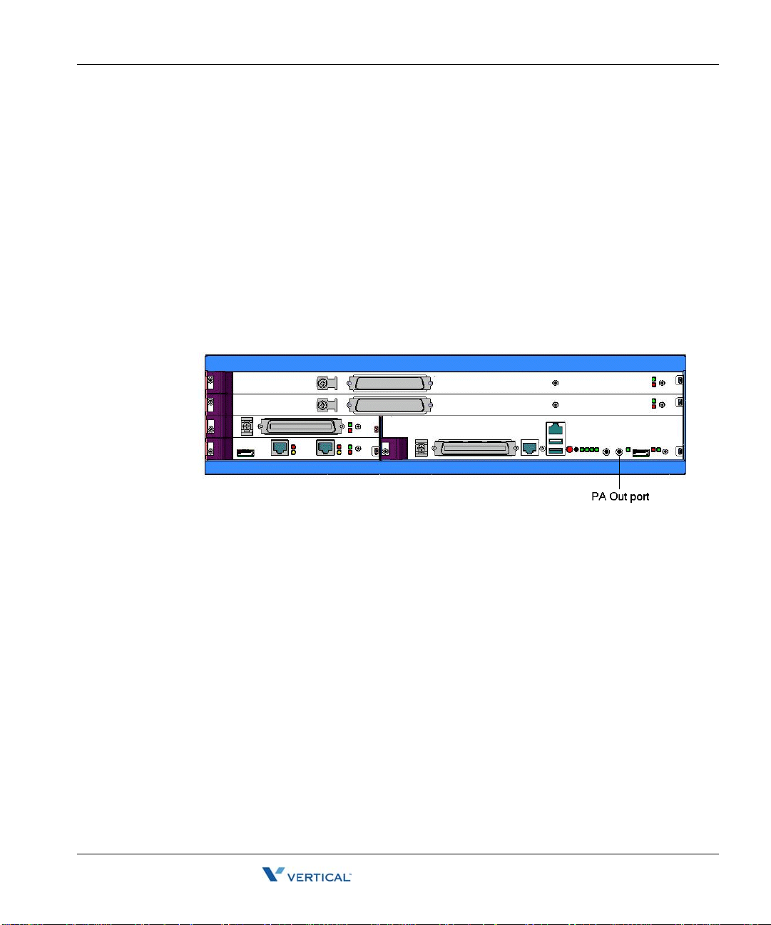
Connecting a paging system 4-31
Release 2.0 Service Pack 1
April 2011
Chapter 4: Setting Up the Wave IP 2500 Server
Connecting a paging system
A paging system allows Wave users to make public announcements over a loudspeaker.
The Wave Server is compatible with most standard paging systems that connect via a 3.5 mm
stereo plug. If a cable is not provided, you must purchase one separately.
Note: Although a stereo cable is required, only one channel is used for paging.
Caution: Always follow the instructi ons supplied by the manufactu rer of your paging system
when installing and connecting the system to avoid possible injury to yourself or damage to the
equipment.
To connect a paging system:
1. Locate the audio output port (labeled PA Ou t) on the front of the ISC1.
2. Connect the cable from your paging system to the port.
3. Enable paging in the General Settings applet of the Global Administrator Management
Console. See the Wave Global Administrator Guide for more information.
Wave Server Installation Guide

Connecting a DSS Console 4-32
Release 2.0 Service Pack 1
April 2011
Chapter 4: Setting Up the Wave IP 2500 Server
Connecting a DSS Console
The Edge 700 Direct Station Selection (DSS) 48-Button Console expands a receptionist’s
digital phone with 48 additional flexible buttons with LEDs to connect to system endpoints such
as user extensions. Up to 5 DSS Consoles can be associated with a single digital phone,
providing up to 240 additional buttons.
The DSS Console connects t o a digital st ation port on any of the fol lowing modu les or card s on
the Wave IP 2500:
• 12- Port Digital Station Module (VW-12DS2-M)
• 24- Port Digital Station Module (VWU-24DS2-M)
• 48-Port Digital Station Card (VW-48DS2-C) for Edge 700/Vodavi Phone support
For instructions on how to configure a DSS Console for a user, see “The Phone \ DSS Consoles
tab” in Chapter 10 in the Wave Global Administrator Guide.
To connect a DSS Console:
1. Locate an unused port on the digital station module or card.
2. Connect the DSS Console to the digital station port using an RJ-11 cable. The maximum
cable length between the Wave Server and the DSS Console is 1968 feet (600 m).
Note: There is no physical connection between the DSS Console and the user’s digital
phone.
Wave Server Installation Guide

Chapter 5
Release 2.0 Service Pack 1
April 2011
Connecting to the Wave ISM from the
administrator PC
CHAPTER CONTENTS
Obtaining all required HotFixes . . . . . . . . . . . . . . . . . . . . . . . . . . . . . . . . . . . . . 5-1
Administrator PC requirements . . . . . . . . . . . . . . . . . . . . . . . . . . . . . . . . . . . . . 5-2
Configuring the administrator PC. . . . . . . . . . . . . . . . . . . . . . . . . . . . . . . . . . . . 5-3
Connecting to the Wave ISM . . . . . . . . . . . . . . . . . . . . . . . . . . . . . . . . . . . . . . . 5-4
Obtaining all required HotFixes
Note the following important information:
• Although you will not apply HotFixes until the next chapter, contact your Vertical
representative at this point to obtain any required HotFixes and other critical information.
Once you have obtained the HotFix CAB files from your Vertical representative, place
them on the hard drive of the administrator PC that you will use to administer the Wave
ISM.
• Be s ure to move the HotFix CAB files to the administrator PC before performing the
steps in “Configuring the administrator PC” on page5-3, where you will change the IP
address of the administrator PC. Once you change th e IP address o f the administ rator PC,
that PC will be dedicated to communicating with the Wave ISM and you will no longer
be able to access your network or go out on the Internet from it to retrieve the HotFix
CAB files.
Wave Server Installation Guide

Administrator PC requirements 5-2
Release 2.0 Service Pack 1
April 2011
Chapter 5: Connecting to the Wave ISM from the administrator PC
Administrator PC requ ir em e nts
The administrator PC must meet the following requirements:
Operating system: The following operating systems can be used:
•
• Microsoft Windows 2000
• Windows Server 2003, base release or higher
• Windows XP SP2 or higher
• Windows Vista, base release or higher
Note: You should have y our Mi cros oft operating system disks on hand i n cas e yo u n eed
to install any Windows components required to connect to the Wave Server.
Processor: Minimum Pentium 233 MHz PC.
•
Memory: Minimum 64 MB RAM.
•
Network connection: TCP/IP connection to the Wave Server via an Ethernet card or
•
modem.
Software:
•
Microsoft Internet Explo rer 6. 0 SP1 or 7.0: Be sure that Internet Explorer is
•
configured to connect directly to the Intern et—do not con nect using a defi ned prox y
server.
Browser pop-up blocker software: Some of the Wave Global Administrator
•
Management Console applets display dialogs and warnings automatically. If you
have installed browser pop-up blocker software on the administrator PC, or popup
blocker software is enabled by default in your browser, these pop-ups may not be
displayed. You can usually configure pop-up blocker software to allow pop-ups
from specific domains or IP addresses.
Java Runtime Environ m ent : Be su re to use the versio n of Java Runtim e
•
Environment (JRE) that came with your Wave Server—do not upgrade to a newer
version that you obtain elsewhere. Failure to use the correct version of JRE may
result in the inability to import and/or activate licenses and other problems.
Wave Server Installation Guide
 Loading...