

Page 1

Hardware & Installation Guide
Release 1.0
November 2010
Page 2

THIS PAGE INTENTIONALLY LEFT BLANK.
Page 3

Vertical Communications, Inc. reserves the right to revise this publication and to make
Release 1.0
November 2010
changes in content without notice.
© 2010 by Vertical Communications, Inc. All rights reserved.
This publication contains propr ietary and confidential information of Vertical Communications, Inc. The contents of this document may not be disclosed, copied or translated by third
parties, in any form, or by any means known, or not now known or concei ved, wi thout prior
explicit written permission from Vertical Communications, Inc.
LIMIT OF LIABILITY/DISCLAIMER OF WARRANTY
Vertical Communications, Inc. makes no representation or warranties with respect to the
accuracy or completeness of the content of this publication and specifically disclaims any
implied warranty of merchantability or fitness for any particular purpose, and shall not be
liable for any loss of profit or any other commercial damage, including but not limited to,
special, incidental, or consequential.
TRADEMARKS
Vertical Communications and the Vertical Communications logo and combinations thereof
are trademarks of Vertical Communications, Inc. All other brand and product names are
used for identification only and are the property of their respective hold ers.
RESTRICTED RIGHTS LEGEND
Use, duplication, or disclosure of the technical dat a contained in this docum ent by the Gov-
ernment is subject to restrictions as set forth in subdivision (c) (1) (ii) of the Rights in Technical Data and Computer Software clause at DFARS 52.227-7013 and/or in similar or
successor clauses in the FAR, or in the DOD or NASA FAR Supplement. Unpublished
rights reserved under the Copyright Laws of the United States. Contractor/manufacturer is
Vertical Communications, Inc., 10 Canal Park, Suite 602, Cambridge, MA 02141-2249.
Page 4

REVISION HISTORY
Release 1.0
November 2010
Release Date Documentation Changes Page No.
1.0 07-10 Initial Release --
Page 5

Contents
Release 1.0
November 2010
Chapter 1 Introduction
Important Safety Instructions - - - - - - - - - - - - - - - - - - - - - - - - - 1-1
Safety Requirements - - - - - - - - - - - - - - - - - - - - - - - - - - - - 1-1
Precaution - - - - - - - - - - - - - - - - - - - - - - - - - - - - - - - - - - - 1-2
Disposal of Old Appliance - - - - - - - - - - - - - - - - - - - - - - - - 1-3
Manual Usage - - - - - - - - - - - - - - - - - - - - - - - - - - - - - - - - 1-4
Chapter 2 System Overview
MBX IP System Highlights - - - - - - - - - - - - - - - - - - - - - - - - - - 2-1
System Connection Diagram - - - - - - - - - - - - - - - - - - - - - - 2-2
System Components - - - - - - - - - - - - - - - - - - - - - - - - - - - - - - 2-3
Specifications - - - - - - - - - - - - - - - - - - - - - - - - - - - - - - - - - - - 2-4
General Parameters - - - - - - - - - - - - - - - - - - - - - - - - - - - - 2-4
Chapter 3 KSU Installation
Pre-Installation - - - - - - - - - - - - - - - - - - - - - - - - - - - - - - - - - - - 3-1
Safety Installation Instructions - - - - - - - - - - - - - - - - - - - - - 3-1
Installation Precautions - - - - - - - - - - - - - - - - - - - - - - - - - - 3-1
Wiring Precautions - - - - - - - - - - - - - - - - - - - - - - - - - - - - - 3-2
Basic Key Service Unit (BKSU) Unpacking - - - - - - - - - - - - 3-3
Expansion Key Service Unit (EKSU) Unpacking - - - - - - - - - 3-4
KSU Diagram, Exterior and Dimension - - - - - - - - - - - - - - - 3-5
Motherboard (MB) & Motherboard Expansion (MBE) Diagrams -
3-6
Power Supply Unit Installation - - - - - - - - - - - - - - - - - - - - - 3-8
Frame Ground Connection - - - - - - - - - - - - - - - - - - - - - - - 3-10
External Backup Battery Installation - - - - - - - - - - - - - - - - 3-11
Types of Connectors - - - - - - - - - - - - - - - - - - - - - - - - - - - 3-12
KSU Mounting - - - - - - - - - - - - - - - - - - - - - - - - - - - - - - - 3-13
Expansion KSU Installation - - - - - - - - - - - - - - - - - - - - - - - - - 3-16
Using Expansion Cable - - - - - - - - - - - - - - - - - - - - - - - - - 3-16
Mounting - - - - - - - - - - - - - - - - - - - - - - - - - - - - - - - - - - - 3-17
Chapter 4 Board Installation
Installing the Boards - - - - - - - - - - - - - - - - - - - - - - - - - - - - - - - 4-1
MBX IP Hardware & Installation Guide
Page 6

Main Processing Board - - - - - - - - - - - - - - - - - - - - - - - - - - - - - 4-2
Release 1.0
November 2010
MPB 100/300 - - - - - - - - - - - - - - - - - - - - - - - - - - - - - - - - - - 4-2
CO Line Boards - - - - - - - - - - - - - - - - - - - - - - - - - - - - - - - - - - 4-14
LCOB4/8/12 (Loop Start CO Line Interface Board) - - - - - - 4-14
PRIB (Primary Rate Interface Board) - - - - - - - - - - - - - - - - 4-21
Extension Boards - - - - - - - - - - - - - - - - - - - - - - - - - - - - - - - - 4-25
SLIB12/24C (with RJ21 connector) - - - - - - - - - - - - - - - - - 4-25
DTIB12C/24C (with RJ21 connector) - - - - - - - - - - - - - - - - 4-30
Function Boards - - - - - - - - - - - - - - - - - - - - - - - - - - - - - - - - - 4-35
VMIB (Voice Mail Interface Board) - - - - - - - - - - - - - - - - - - 4-35
VOIB8/24 (Voice over Internet Protocol Board 8ch./24ch.) - 4-40
Serial to Audio Jack Cable Specification - - - - - - - - - - - - - - 4-44
Chapter 5 Terminal Connection and Wiring Method
Terminal and Door Phone Models - - - - - - - - - - - - - - - - - - - - - - 5-1
Terminal Cabling Distance - - - - - - - - - - - - - - - - - - - - - - - - 5-2
Basic Terminal Connection - - - - - - - - - - - - - - - - - - - - - - - - 5-3
IP 8000 DSS Installation - - - - - - - - - - - - - - - - - - - - - - - - - - 5-9
Connecting Additional Terminals - - - - - - - - - - - - - - - - - - - 5-10
Cable Wiring - - - - - - - - - - - - - - - - - - - - - - - - - - - - - - - - - - - - 5-11
Wall Mount Wiring - - - - - - - - - - - - - - - - - - - - - - - - - - - - - 5-11
Rack Mount Wiring - - - - - - - - - - - - - - - - - - - - - - - - - - - - - 5-12
TOC-2
:
Chapter 6 DECT Installation
Introduction - - - - - - - - - - - - - - - - - - - - - - - - - - - - - - - - - - - - - - 6-1
DECT Installation - - - - - - - - - - - - - - - - - - - - - - - - - - - - - - - - - - 6-3
Board Installation - - - - - - - - - - - - - - - - - - - - - - - - - - - - - - - 6-3
Ferrite Core Installation and Wiring - - - - - - - - - - - - - - - - - - - - 6-11
s
i
h
T
User Subscription/Unsubscription - - - - - - - - - - - - - - - - - - - - - 6-13
tu
a
e
f
e
r
o
n
s
i
t
a
v
a
Chapter 7 Starting the MBX IP System
Initializing Databases - - - - - - - - - - - - - - - - - - - - - - - - - - - - - - - 7-1
Basic Preprogramming - - - - - - - - - - - - - - - - - - - - - - - - - - - - - - 7-1
Before Admin. Programming - - - - - - - - - - - - - - - - - - - - - - - 7-2
Button Explanation - - - - - - - - - - - - - - - - - - - - - - - - - - - - - - 7-2
MBX IP Hardware & Installation Guide
.
.
.
e
m
ti
s
i
th
t
a
e
l
b
a
l
i
Page 7

How to Enter Programming Mode - - - - - - - - - - - - - - - - - - - 7-3
Release 1.0
November 2010
Permanent Update Procedure - - - - - - - - - - - - - - - - - - - - - 7-3
How to Reset the System - - - - - - - - - - - - - - - - - - - - - - - - 7-3
Pre-programming - - - - - - - - - - - - - - - - - - - - - - - - - - - - - - 7-4
Chapter 8 Troubleshooting
Symptons & Solutions - - - - - - - - - - - - - - - - - - - - - - - - - - - - - - 8-1
Index
TOC-3
:
MBX IP Hardware & Installation Guide
Page 8

THIS PAGE INTENTIONALLY LEFT BLANK.
Page 9

Important Safety Instructions 1-1
Release 1.0
November 2010
Chapter 1: Introduction
Chapter 1
Introduction
Important Safety Instructions
Safety Requirements
When using your telephone equipment, basic safety precautions should always be followed to
reduce the risk of fire, electric shock and other personal injury, including the following:
• Please read and understand all instructions.
• Follow all warnings and instructions marked on the product.
• Unplug this product from the wall outlet before cleaning; a damp cloth should be used for
cleaning, do not use liquid or aerosol cleaners.
• Do not use this product near water, such as in a bathtub, washbowl, kitchen sink, or
laundry tub, in a wet basement, or near a swimming pool.
• Do not place this product on an unstable table, stand, or card table; the product may fall,
causing serious damage to the product or serious injury to those nearby.
• Slots and openings in the KSU and the back or bottom are provided for ventilation, to
protect it from overheating, these openings must not be blocked or cove red. The openings
should never be blocked by placing the product on a bed, sofa, or other similar surface.
This product should never be placed ne ar or over a radiator or other heat source. This
product should not be placed in a built-in installation without proper ventilation.
• This product should be operated only from the type of power source indicated on the
product label. If you are not sure of the type of power supply to your location, consul t your
dealer or local power company.
• Do not allow anything to rest on the power cord. Do not locate th is product where th e cord
could be abused by people walking on it.
• Do not overload wall outlets and extension cords as this can result in the risk of fire or
electric shock.
• Never push objects of any kind into this product through KSU slots or connectors as they
may touch dangerous voltage points or short out parts that could result in a risk of fire or
electric shock. Never spill liquid of any kind on the product.
MBX IP Hardware & Installation Guide
Page 10

Important Safety Instructions 1-2
Release 1.0
November 2010
Chapter 1: Introduction
• To reduce the risk of electric shock, do not disassemble this product. Instead, take it to a
qualified person when service or repair work is required. Opening or removing covers may
expose you to dangerous voltages or other risk. Incorrect reassemble can cause electric
shock when the appliance is subsequently used.
• Unplug this product from the wall outlet and refer servicing to qualified service personnel
under the following conditions:
• When the power supply cord or plug is damaged or frayed.
• If liquid has been spilled into the product.
• If the product has been exposed to rain or water.
• If the product does not operate normally by following the operating instructions.
Adjust only those controls that are covered by the operating instructions because
improper adjustment of other controls may result in damage and will often require
extensive work by a qualified technician to rest or e the pr od u ct to no rm a l opera tio n .
• If the product has been dropped or the KSU has been damaged.
• If the product exhibits a distinct change in performance.
• Avoid using a telephone during an electrical storm; there may be a remote risk of electric
shock from lightning.
• In the event of a gas leak, do not use the telephone near the leak.
Precaution
• Keep the system away from heating appliances and electrical noise generating devices
such as florescent lamps, motors and televisions. These noise sources can interfere with
the performance of the MBX IP System.
• This system should be kept free of dust, moisture, high temperature (more than 40
degrees) and vibration, and should not be exposed to direct sunlight.
• Never attempt to insert wires, pins, etc. into the system. If the system does not operate
properly, the equipment should be repaired by an authorized LG-Nortel service center.
• Do not use benzene, paint thinner, or an abrasive powder to clean the KSU. Wipe it with a
soft cloth only.
MBX IP Hardware & Installation Guide
Page 11
Important Safety Instructions 1-3
Release 1.0
November 2010
Chapter 1: Introduction
Caution
• This system should only be installed and serviced by qua lifie d se rvic e pe rs on ne l.
• When a failure occurs which exposes any internal p art s, disconnect the power supply cord
immediately and return this system to your dealer.
• To prevent the risk of fire, electric shock or energy hazard, do not expose this product to
rain or any type of moisture.
• To protect PCB from static electricity, discharge body static before touching connectors
and/or components by touching ground or wearing a ground strap.
Warning: -Danger of explosion if battery is not correctly replaced.
-Replace only with the same or equivalent type recommended by the
manufacturer.
-Dispose of used batteries according to the manufacturer's instructions.
Disposal of Old Appliance
When the displayed symbol (crossed-out wheeled bin) is adhered to a product, it designates
the product is covered by the European Directive 2002/96/EC.
• All electric and electronic products should be only be disposed of in
special collection facilities appointed by government or local/municipal
authorities.
• The correct disposal of your old appliance will help prevent
potential negative consequences for the environment and human
health.
• For more detailed information about disposal of your old
appliances, please contact your city office, waste disposal service or
the place of product purchase.
MBX IP Hardware & Installation Guide
Page 12

Important Safety Instructions 1-4
Release 1.0
November 2010
Chapter 1: Introduction
Manual Usage
This document provides general information covering the hardware description and installation
of the MBX IP System. While every effort has been taken to ensure the accuracy of this
information Vertical makes no warranty of accuracy or interpretations thereof.
Chapter 2 - System Overview
Provides general information on the MBX IP System, including system specifications and
capacity.
Chapter 3 - KSU Installation
Describes detailed instructions for planning the installation site and procedures to install
the MBX IP System.
Chapter 4 - Board Installation
Describes detailed instructions for installing components of the MBX IP Board.
Chapter 5 - Terminal Connection and Wiring Method
Describes the kinds of terminals, maximum distance, and other device connections for the
terminal.
Chapter 6 - DECT Installation
Describes procedures to install the DECT.
Chapter 7 - Starting the MBX IP System
Describes procedures to program MBX IP System.
Chapter 8 - Troubleshooting
Provides information on the MBX IP System and explains common troubleshooting
issues.
MBX IP Hardware & Installation Guide
Page 13

MBX IP System Highlights 2-1
Release 1.0
November 2010
Chapter 2: System Overview
Chapter 2
System Overview
MBX IP System Highlights
Features of the MBX IP System include:
• Flexible System Capacity and architecture
• Minimum daughter board
• Powerful PC application, Remote maintenance via LAN/Modem/RS-232C, Web Admin
• Stable & Enhanced voice features
• Simple installation & efficient system management
• Value-Added features
- Distinctive and Enhanced Voice Mail Function and Multi Language
- Basic CID Function for CO & SLT
- Basic 4 AA Function(default) or 4 VoIP channel and 6 DKT + 6 SLT ports on MPB
- Built in PLL Circuit for ISDN Clock Synchronization, No need cabling
- 8 Poly internal MOH (13 Music resources)
- PSTN/SLT Line Monitoring function for maintenance
- Green Product (DKT/SLT Power save mode by program, Low EMI, PB-Free product)
MBX IP Hardware & Installation Guide
Page 14
MBX IP System Highlights 2-2
Release 1.0
November 2010
Chapter 2: System Overview
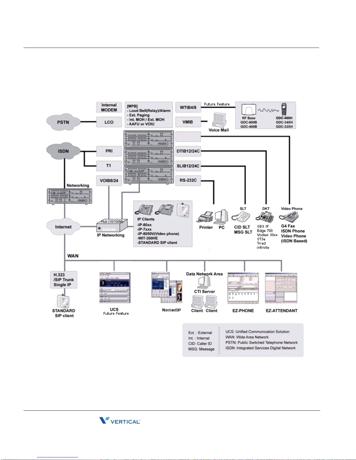
System Connection Diagram
The following Figure shows the components that make up the MBX IP System:
MBX IP Hardware & Installation Guide
Page 15
System Components 2-3
Release 1.0
November 2010
Chapter 2: System Overview
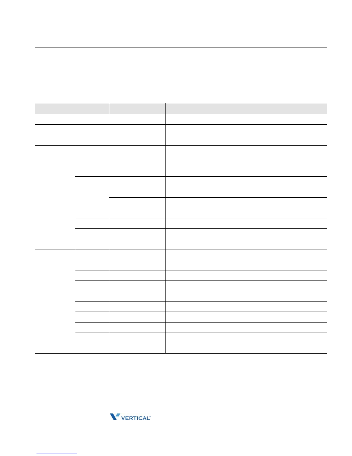
System Components
ITEM OPTION BOARD DESCRIPTION
BKSU - Basic KSU
EKSU - Expansion KSU
PSU - Power Supply Unit (350W)
Main Board MPB100 - Main Processor Board 100
DSIU Digital and Single Line Interface Unit (Default; 6 DKT, 6 SLT)
MODU Modem Unit (Optional; 33Kbps)
MPB300 - Main Processor Board 300
DSIU Digital and Single Line Interface Unit (Default; 6 DKT, 6 SLT)
MODU Modem Unit (Optional; 33Kbps)
Trunk
Boards
Extension
Boards
Function
Boards
ETC WMK - Wall Mount Bracket
LCOB4 - 4 LCO Interface Board
LCOB8 - 8 LCO Interface Board
LCOB12 - 12 LCO Interface Board
PRIB - DCO Interface Board (1 PRI, 30chs)
SLIB12C - 12 SLT Interface Board (RJ21)
SLIB24C - 24 SLT Interface Board (RJ21)
DTIB12C - 12 DKT Interface Board (RJ21)
DTIB24C - 24 DKT Interface Board (RJ21)
WTIB4 - 4 Base Wireless Terminal Interface Board
WTIB8 - 8 Base Wireless Terminal Interface Board
VMIB - Voice Mail Interface Board (8 channels, 100hrs)
VOIB8 - 8 VoIP Interface Board
VOIB24 - 24 VoIP Interface Board
MBX IP Hardware & Installation Guide
Page 16
Specifications 2-4
Release 1.0
November 2010
Chapter 2: System Overview
Specifications
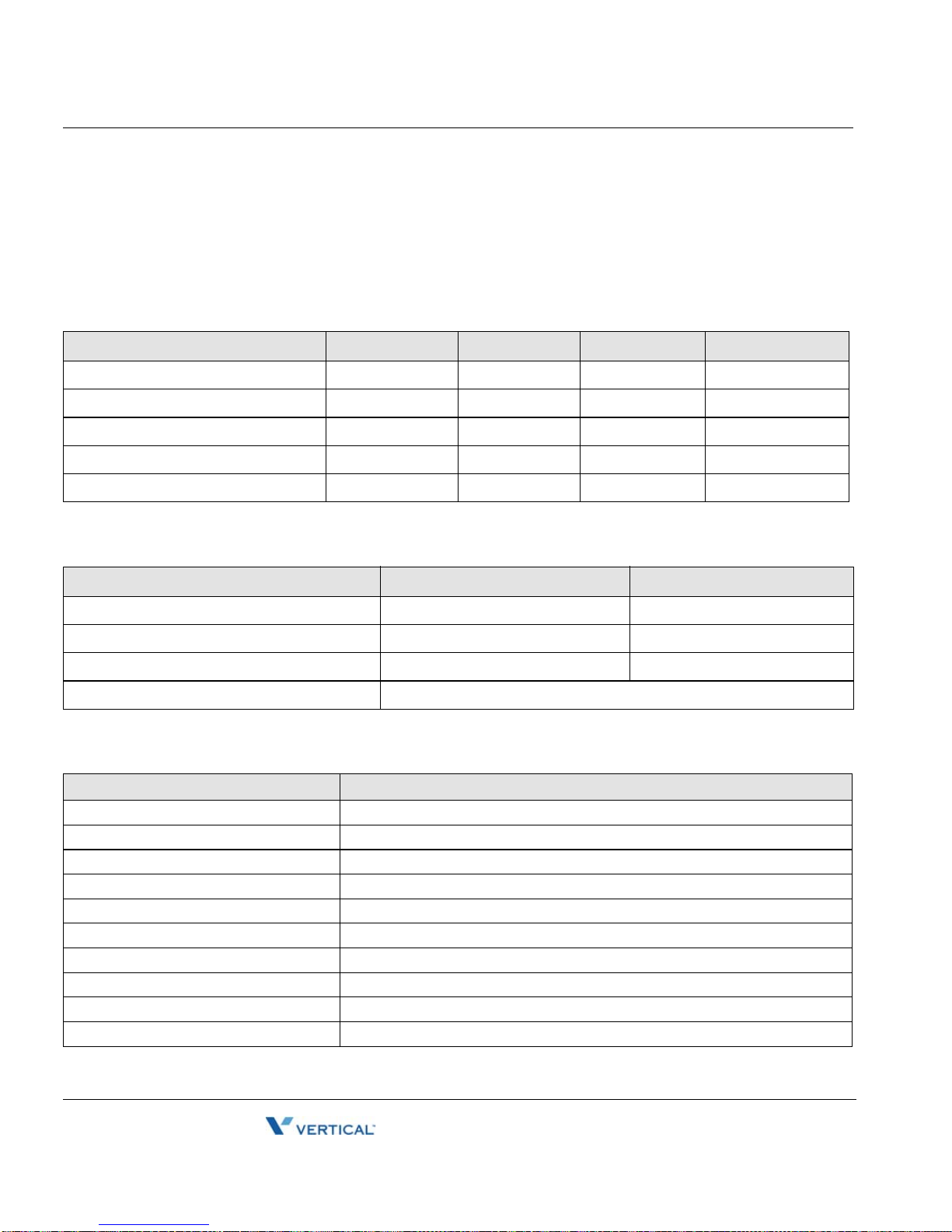
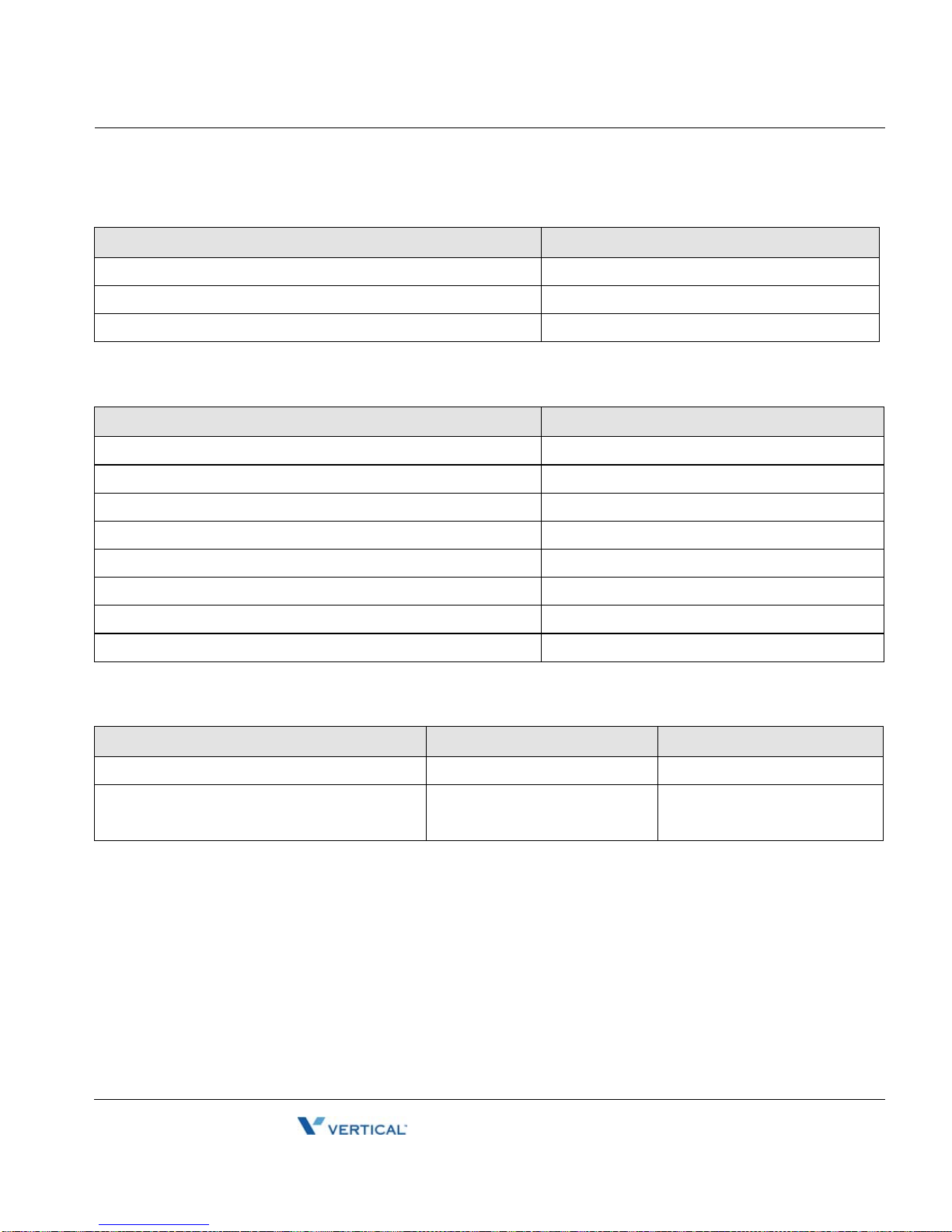
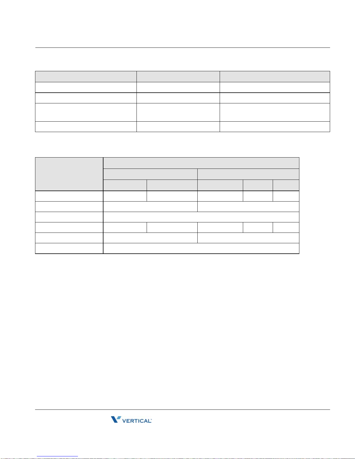
General Parameters
DIMENSION AND WEIGHT
ITEM HEIGHT (in.) WIDTH (in.) DEPTH (in.) WEIGHT(lbs)
BKSU 6.7006 17.3224 12.8107 13.6686
EKSU 6.7006 17.3224 12.8107 13.7788
Digital Keyset .41537 7.9919 4.8817 1.9841
Digital DSS/DLS Console 6.0628 6.8895 4.3699 .8815
Digital ICM/Door Box 1.2598 5.1967 3.8975 1.1023
ENVIRONMENT
ITEM DEGREES ( °C) DEGREES ( °F)
Operation Temperature 0-40 32-104
Optimum Operation Temperature 20-26 68-78
Storage Temperature 10-70 32-158
Relative Humidity 0-80% non-condensing
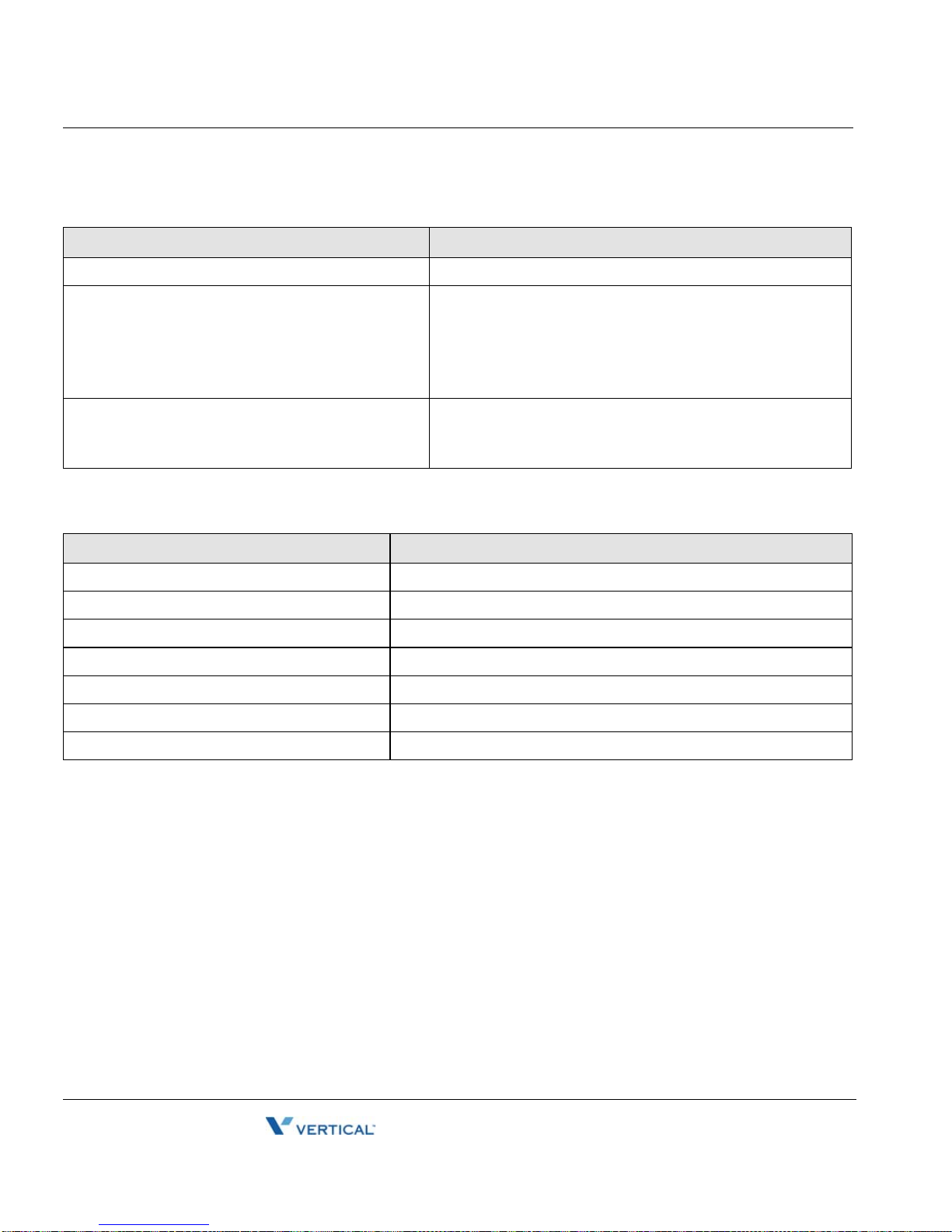
SYSTEM ELECTRICAL
ITEM SPECIFICATION (PSU)
1. Power Supply -
- AC Voltage Input 100 - 240 Volt AC @47-63Hz
- AC Power 350W
- AC Input Fuse 6.3A @ 250Volt AC
- DC Output Voltage + 5, + 30Volt DC
- Efficiency Above 80%
2. Battery Backup -
- PSU Input Voltage 24Volt DC
- PSU Battery Fuse 15.0A @250Volt AC
- Charging Current Max. 1A
MBX IP Hardware & Installation Guide
Page 17
Specifications 2-5
Release 1.0
November 2010
Chapter 2: System Overview
PSU FAN
ITEM SPECIFICATION
Maker / part number POWERLOGIC / PLA07015B05H
Dimensions 70 X 70 X 15 (mm)
Rated voltage +5V
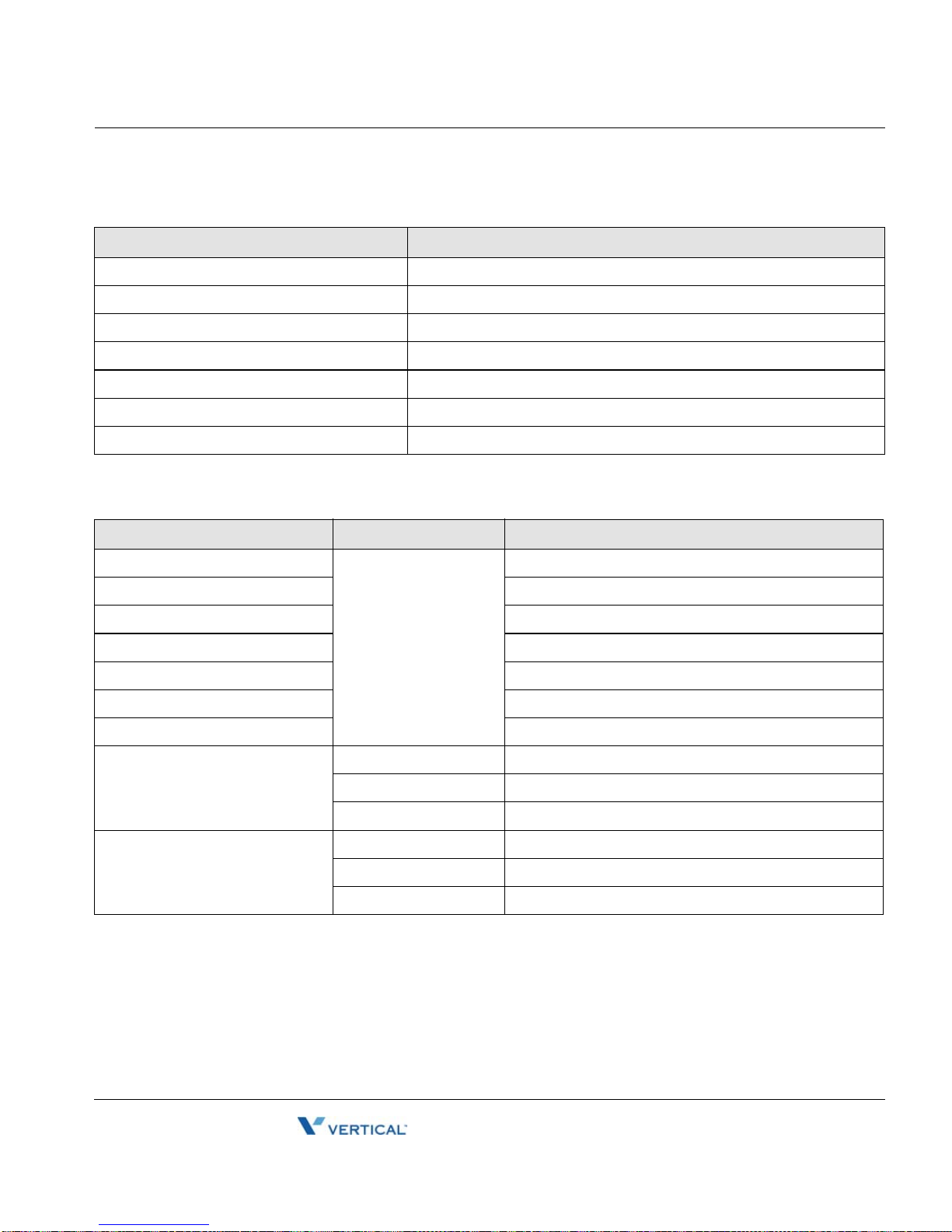
DECT BASE STATION
.
..
ITEM SPECIFICATION
t
a
ble
a
Power feeding +30V DC
is
e
r
u
is
f
at
e
Transmission Max Power 250mW
Th
Access Method/Duplex TDMA/TDD
Frequency Band 1,880 - 1,900MHz
n
o
t
a
l
ai
v
t
is
h
t
i
m
e
Channel Spacing 1.728MHz
im
Modulation GFSK
abl
l
i
a
Data rate 1.152Mbps
at
e
f
s
i
Max. Base Station distance from the WTIB 600m (twisted 2-pair cable)
Th
STATION DISTANCE FROM THE SYSTEM
Digital Keyset 1641 1082
Single Line Telephone DSIU
SLIB12C/SLIB24C -- --
u
s
i
e
r
av
t
o
n
ITEM AWG 22 (ft) AWG 24 (ft)
t
a
e
t
h
is
t
..
.
e
MBX IP Hardware & Installation Guide
Page 18
Specifications 2-6
Release 1.0
November 2010
Chapter 2: System Overview
CO LOOP
ITEM SPECIFICATION
Ring Detect Sensitivity 30Vrms @20-50Hz
DTMF Dialing
Frequency Deviation
Signal Rise Time
Tone Duration, on time
Inter-digit Time
Less than +/- 1.8 %
Max. 5ms
Min. 50ms
Min. 30ms
Pulse Dialing
Pulse Rate
Break/Make Ratio
10 pps 60/40% or 66/33%
MPB VOIP
ITEM SPECIFICATION
LAN Interface 10 / 100 Base-T Ethernet (IEEE 802.3)
Speed 10 Mbps or 100 Mbps (Auto-Negotiation)
Duplex Half Duplex or Full Duplex (Auto-Negotiation)
VoIP Protocol H.323 Revision 2
Voice Compression G.711/G.729A/G.723.1
Voice/Fax Switching T.38
Echo cancellation G.168
MBX IP Hardware & Installation Guide
Page 19
Specifications 2-7
Release 1.0
November 2010
Chapter 2: System Overview
VOIB8/VOIB24
ITEM SPECIFICATION
LAN Interface 10 / 100 Base-T Ethernet (IEEE 802.3)
Speed 10 Mbps or 100 Mbps (Auto-Negotiation)
Duplex Half Duplex or Full Duplex (Auto-Negotiation)
VoIP Protocol H.323 Revision 2
Voice Compression G.711/G.729/G.723.1
Voice/Fax Switching T.38
Echo Cancellation G.165
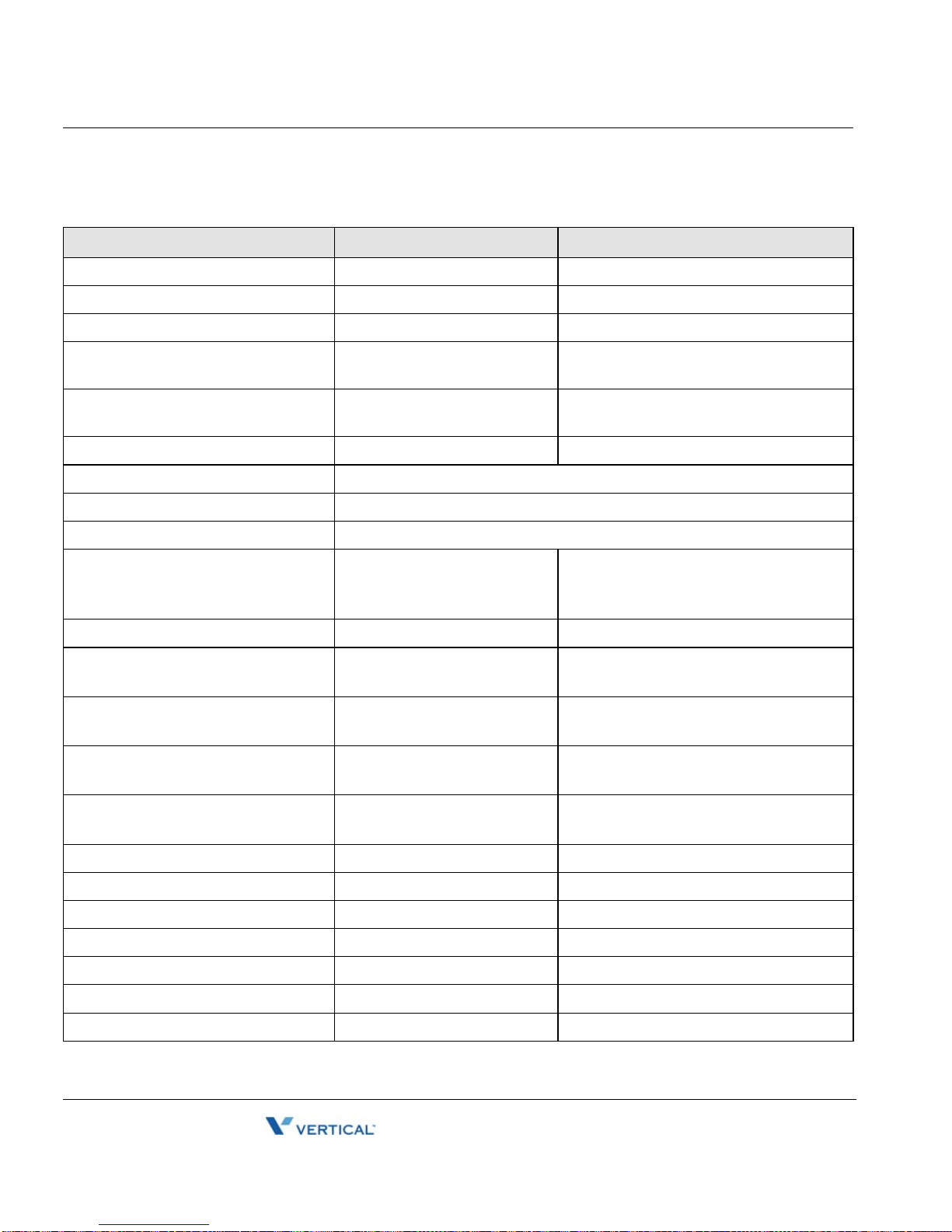
OTHER SYSTEM SPECIFICATIONS
ITEM DESCRIPTION SPECIFICATION
CPU - M82805G, ARM9 Dual core (32bit, 375MHz)
Switching Device ACT2, Custom Mixed-Signal ASIC Device
Memory Back-up Duration 7years
Ring Signal 70Vrms, 25Hz
External Relay Contact 1A @30Volt DC
External Music Port 0dBm @600ohm
External Paging Port 0dBm @600ohm
MODU Analog Modem Bell, ITU-T, V.34 V.32BIS, V.90
Speed 300bps up to 33Kbps speed rate
Connection Automatic rate negotiation
USB Version USB 1.1 compliant
Speed Max. 12Mbps
Mode Host Mode (Memory stick) only
MBX IP Hardware & Installation Guide
Page 20
Specifications 2-8
Release 1.0
November 2010
Chapter 2: System Overview
SYSTEM CAPACITY
DESCRIPTION CAPACITY/BOARD TOTAL
Time Slots - 144 per KSU, Total Max 432
Max Ports - 200 (MPB100), 414 (MPB300)
CO Line Ports - 80 (MPB100) , 240 (MPB300)
Max Direct Station (DKT, SL T, DSS,
- 120 (MPB100), 324 (MPB300)
So) Connections
LAN Port 1/MPB, 1/VOIB8,VOIB24
1
1/VMIB
MODEM Channel 1/MODU 1
Attendant Positions 5/Tenant Tenant Group 5 (MPB100), 9 (MPB300) Intercom Links Non-Blocking Paging
- All Call
- Internal
- 1 zone
15 zones (MPB100),
30 zones (MPB300)
Station Speed Dial 50 (32 digits) / Station System Speed Dial - 1000 (32 digits) (MPB100)
2000 (32 digits) (MPB300)
Call Log
(Outgoing/Incoming/Missed Call)
- 100 (32 digits)
(Not Protected)
CO Line Group - 24 (MPB100)
72 (MPB300)
Station Group - 20 (50 members/group, MPB100)
Conference 3-13 Party All ports are available
Multi-Conference 3-13 Party Max. 3 groups / 13 party
Internal MOH(13 Music Resources) 1/MPB 1
External MOH 1/MPB 1
External Paging port 1/MPB 1
External Relay Contact 1/MPB 1
Alarm Input 1/MPB 1
50 (50 members/group, MPB300)
MBX IP Hardware & Installation Guide
Page 21
Specifications 2-9
Release 1.0
November 2010
Chapter 2: System Overview
DESCRIPTION CAPACITY/BOARD TOTAL
RS-232C Port 1/MPB, 1/IPP Board 1
USB Port 1/MPB, 1/VMIB 1 Host mode(Memory stick) only
CPT/CID/ CO DTMF Detection
channels
32 channels (MPB100), 64
channels (MPB300)
32 channels (MPB100),
64 channels (MPB300)
PFT Circuit 1/LCOB4, LCOB8, LCOB12 -
SYSTEM MAX. CALL CAPACITY
MAXIMUM PORT
MBX IP, MPB100
EXTENSION TRUNK
DKTU SLT PRI CO IP
1st KSU 102* 102 80 60 80
Total 108 80
138
1st KSU + 2nd KSU 120 120 80 80 80
Total 120 80
200
* DSIU DKT 6 + DTIB24, 4ea
- Max. IP Phone registration : 120
- Max. VMIB : 2ea
MBX IP Hardware & Installation Guide
Page 22

Specifications 2-10
Release 1.0
November 2010
Chapter 2: System Overview
MAXIMUM PORT
MBX IP, MPB300
EXTENSION TRUNK
DKTU SLT PRI CO IP
1st KSU 102 102** 120 60 120
108† 120
Total
1st KSU + 2nd KSU 198 198 180 132 180
216 180
Total
1st + 2nd + 3rd KSU 294 294 240 204 240
324 240
Total
** DSIU SLT 6 + SLIB24, 4ea
† DSIU DKT 6 + DSIU SLT 6 + SLIB24, 4ea (or DTIB24, 4ea)
- Max. IP Phone registration : 324
- Max. VMIB : 3ea
- WTIB4/WTIB8 should be installed on the same KSU when installing more than one WTIB4/8.
- Installed ports are over the capacity, there is an alarm indication at attendant keyset.
SIMPLIFIED MAX. NO OF PORT
Boards Max. Extension Max. Trunk TOTAL
Total IP / TDM
MPB100 120 120 80 200
MPB300 324 324 240 414
MBX IP Hardware & Installation Guide
Page 23

Pre-Installation 3-1
Release 1.0
November 2010
Chapter 3: KSU Installation
Chapter 3
KSU Installation
Pre-Installation
Please read the following guidelines concerning inst allation and connection before installing the
MBX IP System. Be sure to comply with applicable local regulations.
Safety Installation Instructions
When installing the telephone wiring, basic safety precautions should always be followed to
reduce the risk of fire, electric shock and personal injury, including the following:
• Never install the telephone wiring during a lightning storm.
• Never install the telephone jack in wet locations unless the jack is specifically designed for
wet locations.
• Never touch un-insulated telephone wires or term inals unle ss the teleph one line h as been
disconnected at the network interf ace .
• Use caution when installing or modifying telephone lines.
• Anti-static precautions should be taken during installation.
Installation Precautions
The MBX IP System is designed for wall mounting or a free-standing rack. Avoid installing in
the following places:
• In direct sunlight and extremely hot, cold, or humid places (optimal temper ature rang e = 0
to 40oC).
• Places where shocks or vibrations are frequent or strong.
• Dusty places, or places where water or oil may come into contact with the System.
• Near high-frequency generating devices such as sewing machines or electric welding
machines.
• On or near computers, fax machines, or other office equipment, as well as microwave
ovens or air conditioners.
• Do not obstruct the openings on the top of the MBX IP System.
• Do not stack up the Optional Service Boards.
MBX IP Hardware & Installation Guide
Page 24

Pre-Installation 3-2
Release 1.0
November 2010
Chapter 3: KSU Installation
Wiring Precautions
Be sure to follow these precautions when wiring:
• Do not wire the telephone cable in p ar allel with an AC powe r so urce , su ch as a computer,
fax machine, etc. If the cables are run near those wires, shield the cables with metal tubing
or use shielded cables and ground the shields.
• If the cables are run on the floor, use protectors to prevent the wires from being stepped
on. Avoid wiring under carpets.
• Do not use the same power supply outlet for computers, fax machine, and other office
equipment to avoid induction noise interruption when using the MBX IP.
• The power and battery switches must be OFF during wiring. Af ter wiring is completed, the
power switch may be turned ON.
• Incorrect wiring may cause the MBX IP System to operate improperly.
• If an extension does not operate properly, disconnect the telephone from the extension
line and then re-connect, or turn the System power OFF and then ON again.
• Use twisted pair cable for connecting CO lines.
MBX IP Hardware & Installation Guide
Page 25
Pre-Installation 3-3
Release 1.0
November 2010
Chapter 3: KSU Installation
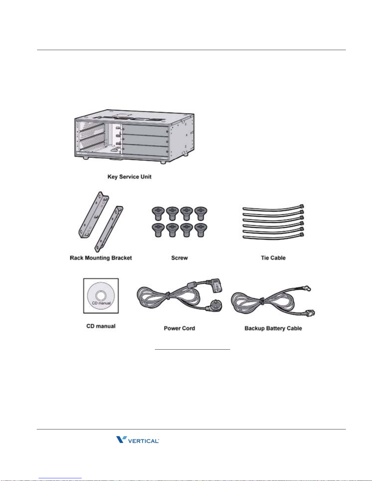
Basic Key Service Unit (BKSU) Unpacking
Open the box and verify the items shown in the Figure below are included:
BKSU Carton Contents
MBX IP Hardware & Installation Guide
Page 26

Pre-Installation 3-4
Release 1.0
November 2010
Chapter 3: KSU Installation
Expansion Key Service Unit (EKSU) Unpacking
Open the box and verify the items shown in the Figure below are included.
EKSU Carton Contents
MBX IP Hardware & Installation Guide
Page 27

Pre-Installation 3-5
Release 1.0
November 2010
Chapter 3: KSU Installation
KSU Diagram, Exterior and Dimension
The Figure below shows the exterior and dimensions of the KSU.
KSU Exterior and Dimension
MBX IP Hardware & Installation Guide
Page 28
Pre-Installation 3-6
Release 1.0
November 2010
Chapter 3: KSU Installation
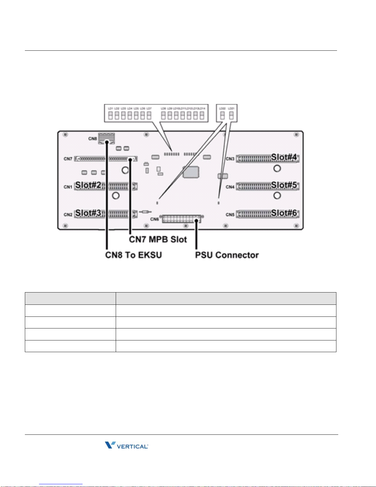
Motherboard (MB) & Motherboard Expansion (MBE) Diagrams
LED Indications
LED DESCRIPTION
LD1 (Blue) MPB Slot Link/Act - ON, Link/Act is established; OFF, Idle
LD2 - LD6 (Blue) Slot #2 - 6 Link/Act - ON, Link/Act is established; OFF, Idle
LD7(Blue) 2nd KSU Link/Act - ON, Link/Act is established; OFF, Idle
LD21, LD22 (Blue) AC Power Indication - ON, AC Powered ON: OFF, AC Powered OFF
MBX IP Hardware & Installation Guide
Page 29
Pre-Installation 3-7
Release 1.0
November 2010
Chapter 3: KSU Installation
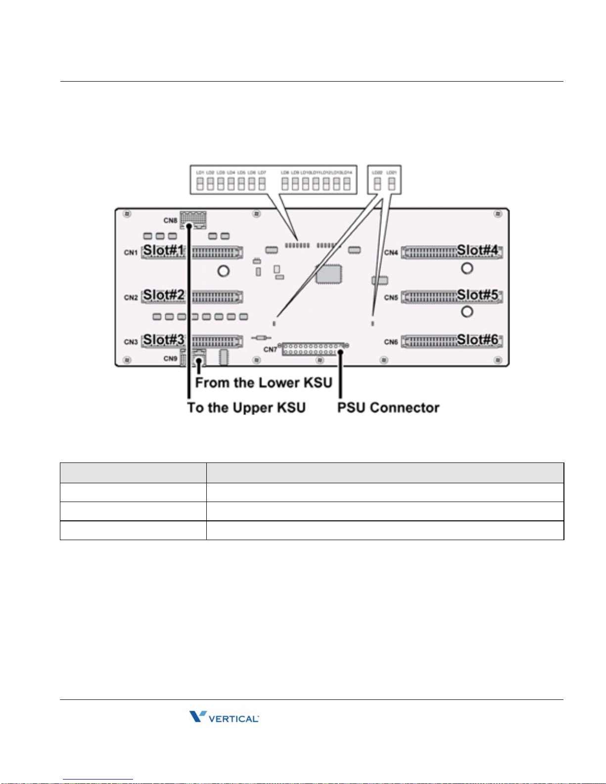
MotherBoard (MB) & Motherboard Expansion (MBE) Diagrams (cont’d)
LED Indications
LED DESCRIPTION
LD1 - LD6 (Blue) Slot #1 - 6 Link/Act - ON, Link/Act is established; OFF, Idle
LD7 (Blue) Upper KSU Link/Act - ON, Link/Act is established; OFF, Idle
LD21, LD22 (Blue) AC Power Indication - ON, AC Powered ON: OFF, AC Powered OFF
MBX IP Hardware & Installation Guide
Page 30
Pre-Installation 3-8
Release 1.0
November 2010
Chapter 3: KSU Installation
Power Supply Unit Installation
The Power Supply Unit (PSU) can be installed in the BKSU and the EKSU by the installer . Make
sure that the KSU is not plugged into an outlet. The PSU is located a t the rear side of the KSU
and is capable of providing three kinds of power sources to the MB an d MBE through the 20-pin
connector, CN6/CN7 (refer to the following Table).
AC Input Voltage and Fuse Rating
INPUT VOLTAGE CONNECTION FUSE RATINGS
100V AC – 240V AC CN6/CN7 on the MB/MBE 6.3A @ 250V
PSU Capacity
PSU TYPE +5V DC +27V DC +30V DC
PSU (SMPS) 10.0A 1A (Battery charge) 10A
1. Insert the PSU along the guide rails on the rear side of the MBX IP system.
2. Slide and press PSU to the CN6 (PSU Connector) on MB and the CN7 (PSU
Connector) on MBE.
3. To affix securely, turn the 4 screws clockwise (as shown in illustration #2 below).
MBX IP Hardware & Installation Guide
Page 31

Pre-Installation 3-9
Release 1.0
November 2010
Chapter 3: KSU Installation
PSU Installation
NOTE:
1. When turning-Off the PSU of 1st KSU, the 2nd and 3rd PSUs first should be
turned-Off, or the MBX IP will automatically shut them off.
2. The 1st and 2nd KSUs will work independent of the 3rd KSU (power shut-Off).
3. The 1st KSU will work independent of the 2nd KSU (powered-Off), however, the 3rd
KSU cannot work without the 2nd KSU powered-On.
4. The MPB (100/300) will be recommended to reset if the 2nd and 3rd KSUs are
turned-On/Off.
5. The PSU Fan may need to b e r ep laced so metime s during lifecycle use of the MBX IP
(refer to Fan Specification on page 2-5).
MBX IP Hardware & Installation Guide
Page 32

Pre-Installation 3-10
Release 1.0
November 2010
Chapter 3: KSU Installation
Frame Ground Connection
It is very important that the frame of the MBX IP System is grounded:
1. Turn the grounding screw counter clockwise to loosen, as shown in the figure below.
2. Insert the grounding wire and tighten the screw.
3. Then connect the grounding wire to an appropriate ground source (refer to Caution).
C
AUTION:
• The equipment should be connected to a socket-outlet with a protective ground
connection.
• For ground wire, green-and-yellow insulation is required and the cross-sectional
area of the conductor must be more than UL 1015 AWG#18 (1.0mm). It is
recommended that the ground wire is shorter than 1m (3.28ft).
• Proper grounding is very important to protect the MBX IP system from external
noise or to reduce the risk of electrocution in the event of lightning strike.
• Be sure to comply with applicable local regulations.
MBX IP Hardware & Installation Guide
Page 33

Pre-Installation 3-11
Release 1.0
November 2010
Chapter 3: KSU Installation
External Backup Battery Installation
In case of power failure, the external backup batteries automatically maintain uninterrupted
power for the MBX IP System. The external batteries must provide 24V DC; this is generally
accomplished by connecting two 12V batteries in a series arrangement as shown:
1. Connect the backup battery cable with 2 identical batteries (12V DC X 2).
2. Connect the external back up battery cable to the battery connector of the PSU.
3. After connecting the external backup battery cable, turn on the battery switch.
NOTE: The cable used to connect the battery is supplied with the KSU from the manufacturer.
Battery operation is controlled by the PSU. The PSU will provide charging current to the
batteries during normal AC power operation at a maximum of about 1A (PSU). PSU battery
operation will be halted if the AC power is reconnected or if the battery voltage is too low to
maintain full-system operation.
The external batteries can maintain System operation as needed depending on several
elements such as battery charge status, condition and capacity of the batteries, and System
configuration (number of Station ports).
The length of time that the system will operate on the batteries is dependent on several
elements including, battery charging state, condition of the batteries, capacity of the batteries,
and the size of the system (number of station ports). The chart below gives the approximate
back-up time for several system sizes and different battery capacities in ampere-hours.
MBX IP Hardware & Installation Guide
Page 34

Pre-Installation 3-12
Release 1.0
November 2010
Chapter 3: KSU Installation
Battery Capacities
BATTERY CAPACITY DKT 24 PORTS DKT 72 PORTS DKT 120 PORTS
20AH 6 hours 3 hours 1.5 Hours
40AH 12 hours 6 hours 3 hours
AUTION:
C
• It is recommended to use an external backup battery fuse between the battery
and the System.
• Recommended battery capacity is more than 24V/20AH MF
• Carefully check the battery polarity with cable colors (Red and Blue) when
connecting the battery to the System.
• Make sure that you do not short out the external batteries and cables.
• There is a danger of explosion if external batteries are incorrectly replaced.
Replace only with the same or equivalent type recommended by the
manufacturer. Dispose of used batteries according to the manufacturer's
instructions.
Types of Connectors
CONNECTOR TYPE PIN NUMBER BOARD REMARK
RJ21 (Male)
RS-232C MPB Serial Port
Serial to Audio Jack VOIB8, VOIB24, VMIB, PRIB,
(Female)
MPB, VOIB8, VOIB24, VMIB,
PRIB, DSIU, LCOB4, LCOB8,
LCOB12, DTIB12C, DTIB24C,
SLIB12C, SLIB24C
WTIB4, WTIB8
DKT Ports
SLT Ports
Serial Port
MBX IP Hardware & Installation Guide
Page 35

Pre-Installation 3-13
Release 1.0
November 2010
Chapter 3: KSU Installation
CONNECTOR TYPE PIN NUMBER BOARD REMARK
Audio Jack MPB EXT MOH Port EXT
PAGE Port
KSU Mounting
Wall Mounting
1. Attach the mounting template for accurate placement to the wall and drill the hole.
2. Install 12 anchor plugs into the wall using the mounting template shown below .
3. Insert 12 included screws into the 12 anchor plugs.
4. Hook Wall Bracket onto installed screws.
5. Attach Wall Shelf to the bottom of KSU and affix 2 shelves to the KSU using the 8
screws provided.
6. Hook the Wall Shelf onto the Wall Bracket, make sure the System slides down seurely.
7. Affix the Wall Shelf to the Wall Bracket using the 8 screws provided.
MBX IP Hardware & Installation Guide
Page 36

Pre-Installation 3-14
Release 1.0
November 2010
Chapter 3: KSU Installation
KSU Wall Mounting
MBX IP Hardware & Installation Guide
Page 37

Pre-Installation 3-15
Release 1.0
November 2010
Chapter 3: KSU Installation
Rack Mounting
Attach System to the rack securely by tightening the screws clockwise. These screws are
supplied with the rack.
KSU Rack Mounting
MBX IP Hardware & Installation Guide
Page 38

Expansion KSU Installation 3-16
Release 1.0
November 2010
Chapter 3: KSU Installation
Expansion KSU Installation
Using Expansion Cable
1. Turn the screw counter-clockwise to loosen and then remove the Dummy Cap. Also, the
Dummy Cap of the 2nd KSU should be opened in the same m anner at three KSU system.
2. To operate the System, each KSU should be connected using the Expansion cable as
shown below. Make sure that the Expansion cable is connected correctly, and not facing
the wrong direction.
3. Connect Fasteners with screws to affix the MBX IP system.
NOTE: Be careful not to bend the pins of connectors.
- When the Expansion Cable is inserted in an uneven manner, the connector pins
(male) on MB/MBE may be bent. So, be careful when making connections.
- Before connection of Expansion Cable, remove Dummy Caps and Dummy Plates.
Expansion KSU Installation
MBX IP Hardware & Installation Guide
Page 39

Expansion KSU Installation 3-17
Release 1.0
November 2010
Chapter 3: KSU Installation
Mounting
Wall Mounting
1. Attach the mounting template included for accurate placement to the wall and make the
hole.
2. Install 12 anchor plugs into the wall and insert 12 included screws to the anchor plugs.
3. Hook Wall Bracket to the installed screws (as shown below).
4. Attach Wall Shelf to the bottom of the KSU and affix using the 8 screws provided.
5. Hook the Wall Shelf onto the Wall Bracket, making sure that the System slides down
securely.
6. Affix the Wall Shelf to the Wall Bracket using the 8 screws provided.
7. Install the 2nd and 3rd KSU and then affix them by using the fasteners.
MBX IP Hardware & Installation Guide
Page 40

Expansion KSU Installation 3-18
Before Board Installation,
Dummy cap on top of KSU
should be open, and Dummy
plates in front should be removed
in order to connect Expansion
NOTE --
Cable as shown on page 3-17.
Release 1.0
November 2010
Chapter 3: KSU Installation
Expansion KSU Wall Mounting
MBX IP Hardware & Installation Guide
Page 41

Expansion KSU Installation 3-19
Before Board Installation,
Dummy cap on top of KSU
should be open, and Dummy
plates in front should be removed
in order to connect Expansion
NOTE --
Cable as shown on page 3-17.
Release 1.0
November 2010
Chapter 3: KSU Installation
Rack Mounting
Attach System to the rack securely by tightening the screws clockwise.
KSU Rack Mounting
MBX IP Hardware & Installation Guide
Page 42

THIS PAGE INTENTIONALLY LEFT BLANK.
Page 43

Installing the Boards 4-1
Release 1.0
November 2010
Chapter 4: Board Installation
Chapter 4
Board Installation
Installing the Boards
Prior to installing the Boards, the following should be considered:
CAUTION: - First, check that electrical Power is turned OFF before installation of board.
- To protect the System from static electricity, do not directly touch the boards; to discharge
static, touch a grounded object, or wear a grounding strap.
To install the Board, perform the following steps:
1. Slide the board along the guide rails and hold the board as shown in second figure,
carefully insert the Board in the direction of the arrow so that the Board securely
inserts with the connector on the Mother Board.
2. Press the screw to turn it clockwise and affix it securely.
Board Installation
MBX IP Hardware & Installation Guide
Page 44

Main Processing Board 4-2
Release 1.0
November 2010
Chapter 4: Board Installation
Main Processing Board
MPB 100/300
The Main Processor Board controls communication between the p eripheral Board, sup ervises
all resources in the system, controls the gain adjustment of the PCM signal, generates the
System tones, and manages System call processing. The MPB100/MPB300 shown on the next
two pages incorporates the main control of the System, and is composed of the microprocessor
and memory, the PCM management and miscellaneous functional circuits.
>>> MPB100/MPB300 must
be installed in the MPB slot of the Basic KSU (BKSU).
MBX IP Hardware & Installation Guide
Page 45

Main Processing Board 4-3
Release 1.0
November 2010
Chapter 4: Board Installation
MPB 100/300 (cont’d)
Main Processing Board
The following devices and functions are included on the MPB100/MPB300:
• Main Processor: MINDSPEED ARM9 Dual Core, M82805G, 375MHz
• PCM Voice Processing circuit (ACT2) -PCM voice switching, System Tone/Gain Control
• Tone (DTMF/CPT) Detection/CID Signal (FSK/DTMF/RCID) Detection/CID Generation
• Real Time Clock for System Time/Date
• System Memory [SDRAM / SRAM / Flash ROM / NAND Flash] for Operation
• PLL Circuit for External ISDN Line Clock Synchronization
• 1 Internal MOH - 13 Music resources
• 4 VoIP channel (default)
• MODU (Option) Interface
• Basic DSIU Included 6 DKTs and 6 SLTs
• 4 Status Indication LEDs
• 1 RS-232C monitoring port
MBX IP Hardware & Installation Guide
Page 46

Main Processing Board 4-4
Release 1.0
November 2010
Chapter 4: Board Installation
• 1 Reset Button
• 1 Switch for Admin Database back up
• 1 External MOH port and 1 External Paging port
• 1 Alarm Detection port and 1 Relay Contact for general purpose
• 1 USB port for DB upload and Download, SW upgrade with Memory stick
• 1 Ethernet port - System maintenance, MP/PP SW upgrade / Basic 4 channel VoIP
Differences between MPB100 and MPB300
ITEM MPB100 MPB300 REMARK
SRAM 2 ea (4MB) 4 ea (8 MB) User Database back up
ACT2 1 ea (32 DSP chs) 2 ea (64 DSP chs) DTMF,CPT,CID Detection channels at the same time
MAX Ports 200 414 Available MAX.(Trunk + Extension) Ports
Pin Assignment
MJ4,USB
CONNECTOR PIN NUMBER NO SIGNAL NAME
USB Type A
1 GND
2 D+
3 D4 VBUS (+5V)
MBX IP Hardware & Installation Guide
Page 47

Main Processing Board 4-5
Release 1.0
November 2010
Chapter 4: Board Installation
CN6, MPB
CONNECTOR PIN NUMBER NO SIGNAL NAME FUNCTION
RS-232C
1 Reserved
2 TD Transmitted Data
3 RD Received Data
4 DSR Data Set Ready
5 SG Signal Ground
6 DTR Data Terminal Ready
7 CTS Clear to Send
8 RTS Request to Send
9 Reserved
CN6, PC
CONNECTOR PIN NUMBER NO SIGNAL NAME FU NCTION
RS-232C 1 Reserved
2 RD Received Data
3 TD Transmitted Data
4 DTR Data Terminal Ready
5 SG Signal Ground
6 DSR Data Set Ready
7 RTS Request to Send
8 CTS Clear to Send
9 Reserved
MBX IP Hardware & Installation Guide
Page 48

Main Processing Board 4-6
Release 1.0
November 2010
Chapter 4: Board Installation
Connector, Switch and LED Functions
The MPB is installed in the MPB Slot, providing various kinds of connectors and RJ21 jacks
(refer to the following table).
Connector, Modular Jack and Switch Functions
SWITCH/CONNECTOR, MJ FUNCTIONS REMARK
CN1 MPB100 or MPB300 Installation to the MB 120Pins
CN2, CN3 DSIU installation 20Pins
CN4, CN5 MODU Installation 20Pins, 6Pins
CN6 RS-232C Port Connection 9Pins
CN7 USB Connection (USB Memory Stick only) Host Mode Only
CN10 Emulator Debug port For R&D Test
CN1 1, CN12 CPLD Download for U11(for CN11), U37(for CN12) For R&D/Factory set
SW1 Admin Database Protection SW2 Watch-dog (OFF ; Enable, ON : Disable) Not Assembled at MP
SW3 System Reset Button RV1 Internal 32.768MHz “0” PPM Control For Factory set
PJ1 (Red) External MOH Connection PJ2 (Blue) External PAGE Connection MJ1 LAN Port MJ3 Alarm Sensor and External Relay Contact -
SW1 Functions
SWITCH FUNCTION OFF (DEFAULT) ON
1-1 Database Default at Power ON Enable Disable
1-2 Lithium Battery Back up ON/OFF for Memory and RTC Back up OFF Back up ON
NOTE: Default is all OFF while delivering the board.
After all the boards are installed, and before programming the System, switch 1-1 should be
OFF and then power cycle OFF and ON to initialize the default System database. Once the
database has been initialized, switch 1-1 should be placed in the ON position to protect the User
database and to protect the features being programmed in Admin programming after the
System power up and initialization. Switch 1-2 should be placed in the ON position to feed
physically the Lithium Battery Voltage to SRAM/R TC to protect the User Database and System
Time/Date information, etc.
MBX IP Hardware & Installation Guide
Page 49

Main Processing Board 4-7
Release 1.0
November 2010
Chapter 4: Board Installation
NOTE: As needed, replace the batteries with the same or equ ivalent type recommended by the
manufacturer; the System will not function normally if the battery is replaced incorrectly. Be sure
to dispose of used batteries according to manufacturer instructions and/or local gov’t regulations.
LED Indications
LED DESCRIPTION
LD1 (Blue), TMR Timer, Period ic Toggle — ON, 100msec; OFF, 100msec.
LD2 (Blue), CALL Call Task Status — ON, Call task activated; OFF, Call Task idle
LD3 (Blue), SYNC External ISDN Board Clock synchronization ON: PLL circuit activation by External Clock
from ISDN Board; MBX IP will be operated on the basis of external ISDN clock (refer to
“NOTE”). OFF: PLL activation by Internal Clock;
internal clock.
LD4 (Blue), PWR System DC Power ON Indication – ON, Power ON; OF F, Power OFF
NOTE: When several ISDN boards are installed, Default automatic clock priority of Slots and KSUs will
be as follows unless modified by the Admin. (PGM301):
MBX IP will be operated on the basis of
•Boards - PRIB>Internal Clock
• KSUs
•Slot
- 1st KSU>2nd KSU>3rd KSU
- Slot 1>Slot 2>…>Slot 18
LED Indication (MJ1)
LED DESCRIPTION
1 (Green) Li nk Status LED – ON: Link OK, OFF: No Link
2 (Orange) Speed Status LED – ON: 100Mbps, OFF: 10Mbps
MBX IP Hardware & Installation Guide
Page 50

Main Processing Board 4-8
Release 1.0
November 2010
Chapter 4: Board Installation
DSIU (Digital and Single Line Interface Unit)
The DSIU is included by default on the MPB100/300, and provides 6 Digital Terminal (DKT)
ports and 6 Single Line analog (SLT) ports with FSK (ITU-T V.23 or Bell 202) or DTMF (ITU-T
Q.23) Caller ID function. The 6 SLT ports support the Message W ait Ind ication, DTMF or Pulse
Dial receive, Polarity reversal, sinusoidal ringing generator, -48V DC feeding voltage, 20mA
Current Limitation and GR-909 Line Testing. The connection between the DSIU and ter minal is
connected through RJ21 Modular Jacks.
NOTE:
• Caller ID signal can be either DTMF or FSK based on th e country code enter ed in
the system database.
• Dialing Type (DTMF or DP) and Message Wait Indication (MWI) function is
determined by the selected admin value.
Pin Assignment, MJ1 (DKT Only)
CONNECTOR PIN
NUMBER
RJ21 1
RJ21
PIN
26
2
27
3
28
4
29
5
30
6
31
7
32
8
33
9
34
10
35
11
36
DTIB12/24C
CONNECTOR
DTIB12/24C
DESIGNATION
PAIR PIN
1 1
26
2 227VT-2
3 3
28
4 4
29
5 5
30
6 6 31VT-6
7732VT-7
8833VT-8
9934VT-9
10 10
35
11 11
36
VT-1
VR-1
VR-2
VT-3
VR-3
VT-4
VR-4
VT-5
VR-5
VR-6
VR-7
VR-8
VR-9
VT-10
VR-10
VT-11
VR-11
PORT NOREMARK
1 BL:BLUE
BK:BLACK
2
3
4
5
6
7
8
9
10
11
BN:BROWN
OR:ORANGE
WH:WHITE
GN:GREEN
SL: SILVER
VI:VIOLET
RD:RED
YL:YELLOW
MBX IP Hardware & Installation Guide
Page 51

Main Processing Board 4-9
Release 1.0
November 2010
Chapter 4: Board Installation
CONNECTOR PIN
RJ21
NUMBER
RJ21 12
37
13
38
14
39
15
40
16
41
17
42
18
43
19
44
20
45
21
46
22
47
23
48
24
49
PIN
DTIB12/24C
CONNECTOR
PAIR PIN
12 12
37
13 13
38
14 14
39
15 15
40
16 16
41
17 17
42
18 18
43
19 19
44
20 20
45
21 21
46
22 22
47
23 23
48
24 24
49
DTIB12/24C
DESIGNATION
VT-12
VR-12
VT-13
VR-13
VT-14
VR-14
VT-15
VR-15
VT-16
VR-16
VT-17
VR-17
VT-18
VR-18
VT-19
VR-19
VT-20
VR-20
VT-21
VR-21
VT-22
VR-22
VT-23
VR-23
VT-24
VR-24
PORT NOREMARK
12
13
14
15
16
17
18 -
19
20
21
22
23
24
Pin Assignment, MJ2 (SLT Only)
MBX IP Hardware & Installation Guide
Page 52

Main Processing Board 4-10
Release 1.0
November 2010
Chapter 4: Board Installation
Pin Assignment, Terminal DKT
CONNECTOR PIN
NUMBER
RJ21 1
RJ21
PIN
26
2
27
3
28
4
29
5
30
6
31
7
32
8
33
9
34
10
35
11
36
12
37
13
38
14
39
15
40
16
41
17
42
DKT
CONNECTOR
DESIGNATION
PAIR PIN
1 1
26
2 227VT-2
3 3
28
4 4
29
5 5
30
6 6 31VT-6
7732VT-7
8833VT-8
9934VT-9
10 10
35
11 11
36
12 12
37
13 13
38
14 14
39
15 15
40
16 16
41
17 17
42
VT-1
VR-1
VR-2
VT-3
VR-3
VT-4
VR-4
VT-5
VR-5
VR-6
VR-7
VR-8
VR-9
VT-10
VR-10
VT-11
VR-11
VT-12
VR-12
VT-13
VR-13
VT-14
VR-14
-15
VT
VR-15
VT-16
VR-16
VT-17
VR-17
DKT
PORT NOREMARK
1 BL:BLUE
BK:BLACK
2
3
4
5
6
7
8
9
10
11
12
13
14
15
16
17
BN:BROWN
OR:ORANGE
WH:WHITE
GN:GREEN
SL: SILVER
VI:VIOLET
RD:RED
YL:YELLOW
MBX IP Hardware & Installation Guide
Page 53

Main Processing Board 4-11
Release 1.0
November 2010
Chapter 4: Board Installation
CONNECTOR PIN
RJ21
NUMBER
RJ21 18
43
19
44
20
45
21
46
22
47
23
48
24
49
PIN
DKT
CONNECTOR
PAIR PIN
18 18
43
19 19
44
20 20
45
21 21
46
22 22
47
23 23
48
24 24
49
DKT
DESIGNATION
VT-18
VR-18
VT-19
VR-19
VT-20
VR-20
VT-21
VR-21
VT-22
VR-22
VT-23
VR-23
VT-24
VR-24
PORT NOREMARK
18 -
19
20
21
22
23
24
MBX IP Hardware & Installation Guide
Page 54

Main Processing Board 4-12
Release 1.0
November 2010
Chapter 4: Board Installation
Pin Assignment, Terminal SLT
CONNECTOR PIN
NUMBER
RJ21 1
RJ21
PIN
26
2
27
3
28
4
29
5
30
6
31
7
32
8
33
9
34
10
35
11
36
12
37
13
38
14
39
15
40
16
41
17
42
DTIB12/24C
CONNECTOR
DTIB12/24C
DESIGNATION
PAIR PIN
1 1
26
2 227VT-2
3 3
28
4 4
29
5 5
30
6 6 31VT-6
7732VT-7
8833VT-8
9934VT-9
10 10
35
11 11
36
12 12
37
13 13
38
14 14
39
15 15
40
16 16
41
17 17
42
VT-1
VR-1
VR-2
VT-3
VR-3
VT-4
VR-4
VT-5
VR-5
VR-6
VR-7
VR-8
VR-9
VT-10
VR-10
VT-11
VR-11
VT-12
VR-12
VT-13
VR-13
VT-14
VR-14
-15
VT
VR-15
VT-16
VR-16
VT-17
VR-17
PORT NOREMARK
1 BL:BLUE
BK:BLACK
2
3
4
5
6
7
8
9
10
11
12
13
14
15
16
17
BN:BROWN
OR:ORANGE
WH:WHITE
GN:GREEN
SL: SILVER
VI:VIOLET
RD:RED
YL:YELLOW
MBX IP Hardware & Installation Guide
Page 55

Main Processing Board 4-13
Release 1.0
November 2010
Chapter 4: Board Installation
CONNECTOR PIN
RJ21
NUMBER
RJ21 18
43
19
44
20
45
21
46
22
47
23
48
24
49
MODU (Modem Interface Unit)
The optional MODU should be installed on the MODU connectors (CN4, CN5) of the
MPB100/MPB300, and provides an analog modem connection. It supports Bell, ITU-T, V.34,
V .32BIS, V.90 Protocol at a speed rate of 300bp s up to 33Kbps, and automatic rate negotiation.
PIN
DTIB12/24C
CONNECTOR
PAIR PIN
18 18
43
19 19
44
20 20
45
21 21
46
22 22
47
23 23
48
24 24
49
DTIB12/24C
DESIGNATION
VT-18
VR-18
VT-19
VR-19
VT-20
VR-20
VT-21
VR-21
VT-22
VR-22
VT-23
VR-23
VT-24
VR-24
PORT NOREMARK
18 -
19
20
21
22
23
24
MBX IP Hardware & Installation Guide
Page 56

CO Line Boards 4-14
Release 1.0
November 2010
Chapter 4: Board Installation
CO Line Boards
LCOB4/8/12 (Loop Start CO Line Interface Board)
The MBX IP LCOB (Loop Start CO Interface Board) is a board for PSTN interface on MBX IP
system. There are three kinds of LCOB. The LCOB4 is for 4 po rts PSTN Interface. The LCOB8
is for 8 ports PSTN Interface. The LCOB12 is for 12 po rts PSTN Interface. The LCOB basically
supports Caller Identification (CID) detection, Polarity Reversal (PR) detection, Call Progress
Tone (CPT) detection. And the LCOB has one Power Failure T ransfer (PFT) circu it for 1st port.
>>> The LCOB4/LCOB8/LCOB12 board can be installed on any universal slot.
LCOB4
MBX IP Hardware & Installation Guide
Page 57

CO Line Boards 4-15
Release 1.0
November 2010
Chapter 4: Board Installation
LCOB4/LCOB8/LCOB12 (cont’d)
LCOB8
MBX IP Hardware & Installation Guide
Page 58

CO Line Boards 4-16
Release 1.0
November 2010
Chapter 4: Board Installation
LCOB4/LCOB8/LCOB12 (cont’d)
LCOB12
MBX IP Hardware & Installation Guide
Page 59

CO Line Boards 4-17
Release 1.0
November 2010
Chapter 4: Board Installation
Pin Assignment
LCOB 1st Port (supports PFT function)
CONNECTOR PIN
NUMBER
RJ21 1
RJ21
PIN
26
2
27
3
28
4
29
5
30
6
31
7
32
8
33
9
34
10
35
11
36
12
37
13
38
14
39
15
40
16
41
17
42
LCOB
CONNECTOR
DESIGNATION
PAIR PIN
1 1
26
2 227VT-2
3 3
28
4 4
29
5 5
30
6 6 31VT-6
7732VT-7
8833VT-8
9934VT-9
10 10
35
11 11
36
12 12
37
13 13
38
14 14
39
15 15
40
16 16
41
17 17
42
VT-1
VR-1
VR-2
VT-3
VR-3
VT-4
VR-4
VT-5
VR-5
VR-6
VR-7
VR-8
VR-9
VT-10
VR-10
VT-11
VR-11
VT-12
VR-12
VT-13
VR-13
VT-14
VR-14
-15
VT
VR-15
VT-16
VR-16
VT-17
VR-17
LCOB
PORT NOREMARK
1 BL:BLUE
BK:BLACK
2
3
4
5
6
7
8
9
10
11
12
13
14
15
16
17
BN:BROWN
OR:ORANGE
WH:WHITE
GN:GREEN
SL: SILVER
VI:VIOLET
RD:RED
YL:YELLOW
MBX IP Hardware & Installation Guide
Page 60

CO Line Boards 4-18
Release 1.0
November 2010
Chapter 4: Board Installation
CONNECTOR PIN
RJ21
NUMBER
RJ21 18
43
19
44
20
45
21
46
22
47
23
48
24
49
PIN
LCOB
CONNECTOR
PAIR PIN
18 18
43
19 19
44
20 20
45
21 21
46
22 22
47
23 23
48
24 24
49
LCOB
DESIGNATION
VT-18
VR-18
VT-19
VR-19
VT-20
VR-20
VT-21
VR-21
VT-22
VR-22
VT-23
VR-23
VT-24
VR-24
PORT NOREMARK
18 -
19
20
21
22
23
24
MBX IP Hardware & Installation Guide
Page 61

CO Line Boards 4-19
Release 1.0
November 2010
Chapter 4: Board Installation
LCOB Ports except 1st port
CONNECTOR PIN
NUMBER
RJ21 1
RJ21
PIN
26
2
27
3
28
4
29
5
30
6
31
7
32
8
33
9
34
10
35
11
36
12
37
13
38
14
39
15
40
16
41
17
42
DTIB12/24C
CONNECTOR
DTIB12/24C
DESIGNATION
PAIR PIN
1 1
26
2 227VT-2
3 3
28
4 4
29
5 5
30
6 6 31VT-6
7732VT-7
8833VT-8
9934VT-9
10 10
35
11 11
36
12 12
37
13 13
38
14 14
39
15 15
40
16 16
41
17 17
42
VT-1
VR-1
VR-2
VT-3
VR-3
VT-4
VR-4
VT-5
VR-5
VR-6
VR-7
VR-8
VR-9
VT-10
VR-10
VT-11
VR-11
VT-12
VR-12
VT-13
VR-13
VT-14
VR-14
-15
VT
VR-15
VT-16
VR-16
VT-17
VR-17
PORT NOREMARK
1 BL:BLUE
BK:BLACK
2
3
4
5
6
7
8
9
10
11
12
13
14
15
16
17
BN:BROWN
OR:ORANGE
WH:WHITE
GN:GREEN
SL: SILVER
VI:VIOLET
RD:RED
YL:YELLOW
MBX IP Hardware & Installation Guide
Page 62

CO Line Boards 4-20
Release 1.0
November 2010
Chapter 4: Board Installation
CONNECTOR PIN
RJ21
NUMBER
RJ21 18
43
19
44
20
45
21
46
22
47
23
48
24
49
LED DESCRIPTION
PIN
DTIB12/24C
CONNECTOR
PAIR PIN
18 18
43
19 19
44
20 20
45
21 21
46
22 22
47
23 23
48
24 24
49
LED Indications
DTIB12/24C
DESIGNATION
VT-18
VR-18
VT-19
VR-19
VT-20
VR-20
VT-21
VR-21
VT-22
VR-22
VT-23
VR-23
VT-24
VR-24
PORT NOREMARK
18 -
19
20
21
22
23
24
LD1 (BLUE) The status of 1st port - ON, In use ; OFF, Idle
LD2 (BLUE) The status of 2nd port - ON, In use ; OFF, Idle
LD3 (BLUE) The status of 3rd port - ON, In use ; OFF, Idle
LD4 (BLUE) The status of 4th port - ON, In use ; OFF, Idle
LD5 (BLUE) The status of 5th port - ON, In use ; OFF, Idle
LD6 (BLUE) The status of 6th port - ON, In use ; OFF, Idle
LD7 (BLUE) The status of 7th port - ON, In use ; OFF, Idle
LD8 (BLUE) The status of 8th port - ON, In use ; OFF, Idle
LD9 (BLUE) The status of 9th port - ON, In use ; OFF, Idle
LD10 (BLUE) The status of 10th port - ON, In use ; OFF, Idle
LD11 (BLUE) The status of 11th port - ON, In use ; OFF, Idle
LD12 (BLUE) The status of 12th port - ON, In use ; OFF, Idle
MBX IP Hardware & Installation Guide
Page 63

CO Line Boards 4-21
Release 1.0
November 2010
Chapter 4: Board Installation
PRIB (Primary Rate Interface Board)
The Primary Rate Interface Board (PRIB) provides one (1 ) PRI interface; this interface supports
23 PCM bearer and 1 signaling channels. The PRIB support s pulse dialing, DTMF dialin g, and
MFC-R2 register signaling.
>>> PRIB can be installed on the unive rsal slot No. 1-6 of any KSU excep t the s lot No. 1
of 1st KSU.
CAUTION: For QSIG operation, check the mode setting method and the contact assignments of RJ21
type connector according to the mode of line, TE or NT.
MBX IP Hardware & Installation Guide
Page 64

CO Line Boards 4-22
Release 1.0
November 2010
Chapter 4: Board Installation
NOTE: MBX IP does not support daisy chained clock cable. The ISDN clock priority and
synchronization is controlled by the MPB software (refer to PGM 301). The default clock priority
for Slots and KSUs is as follows unless modified by the Admin.:
- Board - PRIB>Internal Clock
- KSU - 1st KSU> 2nd KSU> 3rd KSU
- Slot - Slot 1>Slot 2>…>Slot 18
Pin Assignment
PRI Port
CONNECTOR PIN
NUMBER
RJ21 1
RJ21
PIN
26
2
27
3
28
4
29
5
30
6
31
7
32
8
33
9
34
10
35
11
36
12
37
13
38
PRI
CONNECTOR
DESIGNATION
PAIR PIN
1 1
26
2 227VT-2
3 3
28
4 4
29
5 5
30
6 6 31VT-6
7732VT-7
8833VT-8
9934VT-9
10 10
35
11 11
36
12 12
37
13 13
38
VT-1
VR-1
VR-2
VT-3
VR-3
VT-4
VR-4
VT-5
VR-5
VR-6
VR-7
VR-8
VR-9
VT-10
VR-10
VT-11
VR-11
VT-12
VR-12
VT-13
VR-13
PRI
PORT NOREMARK
1 BL:BLUE
BK:BLACK
2
3
4
5
6
7
8
9
10
11
12
13
BN:BROWN
OR:ORANGE
WH:WHITE
GN:GREEN
SL: SILVER
VI:VIOLET
RD:RED
YL:YELLOW
MBX IP Hardware & Installation Guide
Page 65

CO Line Boards 4-23
Release 1.0
November 2010
Chapter 4: Board Installation
CONNECTOR PIN
RJ21
NUMBER
RJ21 14
39
15
40
16
41
17
42
18
43
19
44
20
45
21
46
22
47
23
48
24
49
PIN
PRI
CONNECTOR
PAIR PIN
14 14
39
15 15
40
16 16
41
17 17
42
18 18
43
19 19
44
20 20
45
21 21
46
22 22
47
23 23
48
24 24
49
PRI
DESIGNATION
VT-14
VR-14
VT-15
VR-15
VT-16
VR-16
VT-17
VR-17
VT-18
VR-18
VT-19
VR-19
VT-20
VR-20
VT-21
VR-21
VT-22
VR-22
VT-23
VR-23
VT-24
VR-24
PORT NOREMARK
14
15
16
17
18 -
19
20
21
22
23
24
Serial Port
CONNECTOR PIN NUMBER NO SIGNAL HERE
Serial to Audio Jack 1 Signal Ground
2 Receive Data
3 Transmit Data
4 Signal Ground
MBX IP Hardware & Installation Guide
Page 66

CO Line Boards 4-24
Release 1.0
November 2010
Chapter 4: Board Installation
Connectors, Switch, and LED Functions
Connectors and Switch Functions
CONNECTOR/SWITCH FUNCTION REMARK
SW1 Initialization mode (OFF – PRI) Default: PRI mode
SW2 Not used SW3 Reset switch SW4 Depends on S/W function PRI mode: not used
CN1 JTGA port for CPU emulator CN2 JTAG port for DSP emulator CN3 JTAG port for CPLD -
LED Indication
LED PRI MODE REMARK
LD1 PLL Synchronization RED Col or
(ON: Error, OFF: Normal)
LD2 Loss of Signal from the Line LD3 Alarm Indication Signal LD4 Remote Alarm Indication LD5 Multi Frame Error LD6 CRC Error LD7 Normal operation indication
(Activity Indication)
LD8 Indication of channel use Blue Color
Blue (Blink)
(ON: Ch. Use, OFF: All ch. Idle)
PRI Line Connector Configuration
MBX IP Hardware & Installation Guide
Page 67

Extension Boards 4-25
Release 1.0
November 2010
Chapter 4: Board Installation
Extension Boards
SLIB12/24C (with RJ21 connector)
The SLIB12/24C provides 12 (24) single line analog ports with FSK (ITU-T V.23 or Bell 202) or
DTMF (ITU-T Q.23) Caller ID function. The SLIB support s the Message W a it Indication, DTMF
or DP receive, Polarity reversal, sinusoida l ringing g enerator, -48V DC feeding voltage, 20mA
Current Limitation and GR-909 Line Testing. The connection between the SLIB12/24C and
Single Line Telephone is connected using RJ21 cable.
>>> SLIB12/24C can be installed in the universa l slot in any KSU except MPB slot of 1st KSU.
MBX IP Hardware & Installation Guide
Page 68

Extension Boards 4-26
Release 1.0
November 2010
Chapter 4: Board Installation
NOTE:
- Caller ID generation of either DTMF or FSK based on the country code is available.
- Dialing Type (DTMF or DP) and MWI function is supported by the selected admin
value.
- Max. 4 SLIB24Cs can be installed in each KSU.
Pin Assignment
RJ21
CONNECTOR PIN
NUMBER
RJ21 1
RJ21
PIN
26
2
27
3
28
4
29
5
30
6
31
7
32
8
33
9
34
10
35
11
36
12
37
13
38
14
39
SLIB12/24C
CONNECTOR
SLIB12/24C
DESIGNATION
PAIR PIN
1 1
26
2 227VT-2
3 3
28
4 4
29
5 5
30
6 6 31VT-6
7732VT-7
8833VT-8
9934VT-9
10 10
35
11 11
36
12 12
37
13 13
38
14 14
39
VT-1
VR-1
VR-2
VT-3
VR-3
VT-4
VR-4
VT-5
VR-5
VR-6
VR-7
VR-8
VR-9
VT-10
VR-10
VT-11
VR-11
VT-12
VR-12
VT-13
VR-13
VT-14
VR-14
PORT NOREMARK
1 BL:BLUE
BK:BLACK
2
3
4
5
6
7
8
9
10
11
12
13
14
BN:BROWN
OR:ORANGE
WH:WHITE
GN:GREEN
SL: SILVER
VI:VIOLET
RD:RED
YL:YELLOW
MBX IP Hardware & Installation Guide
Page 69

Extension Boards 4-27
Release 1.0
November 2010
Chapter 4: Board Installation
PIN
CONNECTOR
RJ21 15
NUMBER
RJ21
40
16
41
17
42
18
43
19
44
20
45
21
46
22
47
23
48
24
49
PIN
SLIB12/24C
CONNECTOR
PAIR PIN
15 15
40
16 16
41
17 17
42
18 18
43
19 19
44
20 20
45
21 21
46
22 22
47
23 23
48
24 24
49
SLIB12/24C
DESIGNATION
VT-15
VR-15
VT-16
VR-16
VT-17
VR-17
VT-18
VR-18
VT-19
VR-19
VT-20
VR-20
VT-21
VR-21
VT-22
VR-22
VT-23
VR-23
VT-24
VR-24
PORT
NO
15 -
16
17
18
19
20
21
22
23
24
REMARK
Connectors, Switch and LED Functions
Connector and Switch Functions
CONNECTOR/SWITCH FUNCTION REMARK
CN1 JTGA port for CPU emulator For R&D
CN2 JTAG port for FPGA For R&D
CN3 Serial Port 1PIN: Transmit Data
2PIN: Receive Data
3PIN: +5V
4PIN: Ground
MBX IP Hardware & Installation Guide
Page 70

Extension Boards 4-28
Release 1.0
November 2010
Chapter 4: Board Installation
LED Indications
LED FUNCTION REMARK
LD1 The status of 1st port or 13th port ON (Blue) : 1st port Use
ON (Yellow Green) : 13
ON (Blush white) : 1
OFF: Idle
th port Use
st and 13th port Use
LD2 The status of 2
nd port or 14th port ON (Blue) : 2nd port Use
ON (Yellow Green) : 14
ON (Blush white) : 2
nd and 14th port Use
OFF: Idle
LD3 The status of 3
rd port or 15th port ON (Blue) : 3rd port Use
ON (Yellow Green) : 15
ON (Blush white) : 3
rd and 15th port Use
OFF: Idle
LD4 The status of 4th port or 16th port ON (Blue) : 4th port Use
ON (Yellow Green) : 16
ON (Blush white) : 4
th and 16th port Use
OFF: Idle
LD5 The status of 5
th port or 17th port ON (Blue) : 5th port Use
ON (Yellow Green) : 17
ON (Blush white) : 5
th and 17th port Use
OFF: Idle
LD6 The status of 6
th port or 18th port ON (Blue) : 6th port Use
ON (Yellow Green) : 18
ON (Blush white) : 6
th and 18th port Use
OFF: Idle
th port Use
th port Use
th port Use
th port Use
th port Use
LD7 The status of 7th port or 19th port ON (Blue) : 7th port Use
LD8 The status of 8
th port or 20th port ON (Blue) : 8th port Use
ON (Yellow Green) : 19
ON (Blush white) : 7
th and 19th port Use
OFF: Idle
ON (Yellow Green) : 20
ON (Blush white) : 8
th and 20th port Use
OFF: Idle
MBX IP Hardware & Installation Guide
th port Use
th port Use
Page 71

Extension Boards 4-29
Release 1.0
November 2010
Chapter 4: Board Installation
LED FUNCTION REMARK
LD9 The status of 9th port or 21st port ON (Blue) : 9th port Use
ON (Yellow Green) : 21
ON (Blush white) : 9
OFF: Idle
st port Use
th and 21st port Use
LD10 The status of 10
th port or 22nd port ON (Blue) : 10th port Use
ON (Yellow Green) : 22
ON (Blush white) : 10
nd port Use
th and 22nd port Use
OFF: Idle
LD11 The status of 11
th port or 23rd port ON (Blue) : 11th port Use
ON (Yellow Green) : 23
ON (Blush white) : 11
th and 23rd port Use
rd port Use
OFF: Idle
LD12 The status of 12th port or 24th port ON (Blue) : 12th port Use
ON (Yellow Green) : 24
ON (Blush white) : 12
th port Use
th and 24th port Use
OFF: Idle
LD13 ACT, Activation or Normal Operating Blink (Blue Color)
LD14 IN USE ON: Ch. Use
OFF: All channels Idle
MBX IP Hardware & Installation Guide
Page 72

Extension Boards 4-30
Release 1.0
November 2010
Chapter 4: Board Installation
DTIB12C/24C (with RJ21 connector)
The connection between the DTIB12C/24C's modular block and DKT is provided using
RJ21cable. Refer to illustration below.
• DTIB 12C: provides 12 ports.
• DTIB 24C: provides 24 ports.
>>> DTIB can be installed on the universal slot in any KSU except the MPB slot of the 1st KSU.
MBX IP Hardware & Installation Guide
Page 73

Extension Boards 4-31
Release 1.0
November 2010
Chapter 4: Board Installation
DTIB12C/24C with RJ21 connector (cont’d)
NOTE: 4 DTIB24Cs can be installed in each KSU.
MBX IP Hardware & Installation Guide
Page 74

Extension Boards 4-32
Release 1.0
November 2010
Chapter 4: Board Installation
Pin Assignment
DTIB12/24C
CONNECTOR PIN
NUMBER
RJ21 1
RJ21
PIN
26
2
27
3
28
4
29
5
30
6
31
7
32
8
33
9
34
10
35
11
36
12
37
13
38
14
39
15
40
16
41
17
42
DTIB12/24C
CONNECTOR
DTIB12/24C
DESIGNATION
PAIR PIN
1 1
26
2 227VT-2
3 3
28
4 4
29
5 5
30
6 6 31VT-6
7732VT-7
8833VT-8
9934VT-9
10 10
35
11 11
36
12 12
37
13 13
38
14 14
39
15 15
40
16 16
41
17 17
42
VT-1
VR-1
VR-2
VT-3
VR-3
VT-4
VR-4
VT-5
VR-5
VR-6
VR-7
VR-8
VR-9
VT-10
VR-10
VT-11
VR-11
VT-12
VR-12
VT-13
VR-13
VT-14
VR-14
-15
VT
VR-15
VT-16
VR-16
VT-17
VR-17
PORT NOREMARK
1 BL:BLUE
BK:BLACK
2
3
4
5
6
7
8
9
10
11
12
13
14
15
16
17
BN:BROWN
OR:ORANGE
WH:WHITE
GN:GREEN
SL: SILVER
VI:VIOLET
RD:RED
YL:YELLOW
MBX IP Hardware & Installation Guide
Page 75

Extension Boards 4-33
Release 1.0
November 2010
Chapter 4: Board Installation
CONNECTOR PIN
RJ21
NUMBER
RJ21 18
43
19
44
20
45
21
46
22
47
23
48
24
49
Connectors, Switch and LED Functions
PIN
DTIB12/24C
CONNECTOR
DTIB12/24C
DESIGNATION
PAIR PIN
18 18
43
19 19
44
20 20
45
21 21
46
22 22
47
23 23
48
24 24
49
VT-18
VR-18
VT-19
VR-19
VT-20
VR-20
VT-21
VR-21
VT-22
VR-22
VT-23
VR-23
VT-24
VR-24
Connector and Switch Functions
PORT NOREMARK
18 -
19
20
21
22
23
24
CONNECTOR/SWITCH FUNCTION REMARK
CN1 JTAG port for CPLD For R&D only
LED Indications
LED FUNCTION REMARK
LD1 The status of 1st port or 13th port ON (Blue) : 1st port Use
LD2 The status of 2
LD3 The status of 3
ON (Yellow Green) : 13
ON (Blush white) : 1
OFF: Idle
nd port or 14th port ON (Blue) : 2nd port Use
ON (Yellow Green) : 14
ON (Blush white) : 2
OFF: Idle
rd port or 15th port ON (Blue) : 3rd port Use
ON (Yellow Green) : 15
ON (Blush white) : 3
OFF: Idle
th port Use
st and 13th port Use
th port Use
nd and 14th port Use
th port Use
rd and 15th port Use
MBX IP Hardware & Installation Guide
Page 76

Extension Boards 4-34
Release 1.0
November 2010
Chapter 4: Board Installation
LED Indications (cont’d)
LED FUNCTION REMARK
LD4 The status of 4th port or 16th port ON (Blue) : 4th port Use
ON (Yellow Green) : 16
ON (Blush white) : 4
OFF: Idle
LD5 The status of 5
th port or 17th port ON (Blue) : 5th port Use
ON (Yellow Green) : 17
ON (Blush white) : 5
OFF: Idle
LD6 The status of 6
th port or 18th port ON (Blue) : 6th port Use
ON (Yellow Green) : 18
ON (Blush white) : 6
OFF: Idle
LD7 The status of 7
th port or 19th port ON (Blue) : 7th port Use
ON (Yellow Green) : 19
ON (Blush white) : 7
OFF: Idle
LD8 The status of 8
th port or 20th port ON (Blue) : 8th port Use
ON (Yellow Green) : 20
ON (Blush white) : 8
OFF: Idle
LD9 The status of 9
th port or 21st port ON (Blue) : 9th po rt U s e
ON (Yellow Green) : 21
ON (Blush white) : 9
OFF: Idle
LD10 The status of 10
th port or 22nd port ON (Bl ue) : 10th port Use
ON (Yellow Green) : 22
ON (Blush white) : 10
OFF: Idle
LD11 The status of 11
th port or 23rd port ON (Blue) : 11th port Use
ON (Yellow Green) : 23
ON (Blush white) : 11
OFF: Idle
LD12 The status of 12
th port or 24th port ON (Blue) : 12th port Use
ON (Yellow Green) : 24
ON (Blush white) : 12
OFF: Idle
LD13 ACT, Activation or Normal Operating Blink (Blue Color)
LD14 IN USE ON: Ch. Use
OFF: All channels Idle
th port Use
th and 16th port Use
th port Use
th and 17th port Use
th port Use
th and 18th port Use
th port Use
th and 19th port Use
th port Use
th and 20th port Use
st port Use
th and 21st port Use
nd port Use
th and 22nd port Use
rd port Use
th and 23rd port Use
th port Use
th and 24th port Use
MBX IP Hardware & Installation Guide
Page 77

Function Boards 4-35
Release 1.0
November 2010
Chapter 4: Board Installation
Function Boards
VMIB (Voice Mail Interface Board)
The VMIB provides system announcement, ACD/UCD announcement, and User Greeting,
along with a processor and DSP circuitry to support 8 simultaneous channels.
To provide additional channels and/or storage capacity, up to three (3) VMIB may be installed
in the MBX IP system with MPB300 for a maximum capacity of 24 channels.
On an MBX IP system with MPB100, a maximum of two (2) VMIB can be supported for a
maximum capacity of 16 channels.
ITEM CHANNEL SYSTEM GREETING/USER GREETING
VMIB 8 System Greeting (0.5hrs.), User Message (100 Hours)
The VMIB can be installed in the universal slot No. 1-6 of an y KSU exce pt th e MPB slot of 1st
KSU. The maximum 3 VMIB can be installed with MPB300 (MPB100: Max. 2 VMIBs)
MBX IP Hardware & Installation Guide
Page 78

Function Boards 4-36
Release 1.0
November 2010
Chapter 4: Board Installation
NOTE:
- If the VMIB is installed on a System, voice prompt (Default=1-English,
2-3-Blank) should be uploaded for each country.
- MP Software stores voice prompts on U8, Nand Flash of MPB100/MPB300
for each stored language (Korean, English, Italian, Russian, German,
Danish, Hebrew, Spanish, Turkey and Swedish).
- Voice prompt can be changed using the Web Admin, VMIB upgrade
function.
LAN Specification
ITEM SPECIFICATION
LAN Interface 100 Base-T Ethernet (IEEE 802.3)
Speed 100 Mbps (Auto-Negotiation)
Duplex Half Duplex or Full Duplex (Auto-Negotiation)
MBX IP Hardware & Installation Guide
Page 79

Function Boards 4-37
Release 1.0
November 2010
Chapter 4: Board Installation
RJ21, LAN Port
CONNECTOR PIN
NUMBER
RJ21 1
RJ21
PIN
26
2
27
3
28
4
29
5
30
6
31
7
32
8
33
9
34
10
35
11
36
12
37
13
38
14
39
15
40
16
41
17
42
LAN
CONNECTOR
DESIGNATION
PAIR PIN
1 1
26
2 227VT-2
3 3
28
4 4
29
5 5
30
6 6 31VT-6
7732VT-7
8833VT-8
9934VT-9
10 10
35
11 11
36
12 12
37
13 13
38
14 14
39
15 15
40
16 16
41
17 17
42
VT-1
VR-1
VR-2
VT-3
VR-3
VT-4
VR-4
VT-5
VR-5
VR-6
VR-7
VR-8
VR-9
VT-10
VR-10
VT-11
VR-11
VT-12
VR-12
VT-13
VR-13
VT-14
VR-14
-15
VT
VR-15
VT-16
VR-16
VT-17
VR-17
LAN
PORT NOREMARK
1 BL:BLUE
BK:BLACK
2
3
4
5
6
7
8
9
10
11
12
13
14
15
16
17
BN:BROWN
OR:ORANGE
WH:WHITE
GN:GREEN
SL: SILVER
VI:VIOLET
RD:RED
YL:YELLOW
MBX IP Hardware & Installation Guide
Page 80

Function Boards 4-38
Release 1.0
November 2010
Chapter 4: Board Installation
CONNECTOR PIN
NUMBER
RJ21
PIN
LAN
CONNECTOR
LAN
DESIGNATION
PORT NOREMARK
PAIR PIN
RJ21 18
43
19
44
20
45
21
46
22
47
23
48
24
49
18 18
43
19 19
44
20 20
45
21 21
46
22 22
47
23 23
48
24 24
49
VT-18
VR-18
VT-19
VR-19
VT-20
VR-20
VT-21
VR-21
VT-22
VR-22
VT-23
VR-23
VT-24
VR-24
18 -
19
20
21
22
23
24
Serial Port
CONNECTOR PIN NUMBER NO SIGNAL HERE
Serial to Audio Jack 1 Signal Ground
2 Receive Data
3 Transmit Data
4 Signal Ground
MBX IP Hardware & Installation Guide
Page 81

Function Boards 4-39
Release 1.0
November 2010
Chapter 4: Board Installation
USB
CONNECTOR PIN NUMBER NO SIGNAL NAME
USB Type A
1 GND
2 D+
3 D4 VBUS (+5V)
Connectors, Switch, and LED Functions
CONNECTOR/SWITCH FUNCTION REMARK
SW1 4-POLE Dip Switch (Function : not defined) Default: Off
SW2 Battery back-up switch Not Assembled at MP
SW3 Reset switch SW4 Watch-dog Enable/ Disable (OF F:Enab le, ON:Disable) Not Assembled at MP
CN3 JTGA port for CPU emulator For R&D Test
CN4 JTAG port for FPGA For R&D only
LED Indication
LED FUNCTION REMARK
LD1 Normal operation indication (Activity Indication) Blink (blue Color)
LD2 Memory Full (ON – Full, OFF – Usable) LD3 Record (ON – Active, OFF – Idle) LD4 Play (ON – Active, OFF – Idle) MJ1-LD1 (Green/Orange) ON – Link, Blink – Data Transfer MJ1-LD2 (Yellow) ON - 100Mbps, OFF – 10Mbps -
MBX IP Hardware & Installation Guide
Page 82

Function Boards 4-40
Release 1.0
November 2010
Chapter 4: Board Installation
VOIB8/24 (Voice over Internet Protocol Board 8ch./24ch.)
The VOIB8/VOIB24 provides the Ethernet interface for S/W applications and VoIP features.
The VOIB8/24 is used to provide packet relay for remote devices to communicate with the host
and translate between the MBX IP proprietary protocols and other standard protocols (H323,
SIP).
ITEM CHANNEL REMARK
VOIB8 8 VOIB24 24 -
VOIB8/VOIB24 can be installed on universal slot No. 1-6 of any KSU except slot No. 1 of 1st
KSU.
MBX IP Hardware & Installation Guide
Page 83

Function Boards 4-41
Release 1.0
November 2010
Chapter 4: Board Installation
VOIB8/24 (Voice over Internet Protocol Board 8ch./24ch.) con’d
LAN, VoIP Specification
ITEM SPECIFICATION
LAN Interface 100 Base-T Ethernet (IEEE 802.3)
Speed 100 Mbps (Auto-Negotiation)
Duplex Half Duplex or Full Duplex (Auto-Negotiation)
VoIP Protocol H.323 Revision 4, SIP Revision 4
Voice Compression G.711/G.726/G729/G.723.1
Voice/Fax Switching T.38
Echo cancellation G.165
MBX IP Hardware & Installation Guide
Page 84

Function Boards 4-42
Release 1.0
November 2010
Chapter 4: Board Installation
VOIB Port
CONNECTOR PIN
NUMBER
RJ21 1
RJ21
PIN
26
2
27
3
28
4
29
5
30
6
31
7
32
8
33
9
34
10
35
11
36
12
37
13
38
14
39
15
40
16
41
17
42
VOIB
CONNECTOR
DESIGNATION
PAIR PIN
1 1
26
2 227VT-2
3 3
28
4 4
29
5 5
30
6 6 31VT-6
7732VT-7
8833VT-8
9934VT-9
10 10
35
11 11
36
12 12
37
13 13
38
14 14
39
15 15
40
16 16
41
17 17
42
VT-1
VR-1
VR-2
VT-3
VR-3
VT-4
VR-4
VT-5
VR-5
VR-6
VR-7
VR-8
VR-9
VT-10
VR-10
VT-11
VR-11
VT-12
VR-12
VT-13
VR-13
VT-14
VR-14
-15
VT
VR-15
VT-16
VR-16
VT-17
VR-17
VOIB
PORT NOREMARK
1 BL:BLUE
BK:BLACK
2
3
4
5
6
7
8
9
10
11
12
13
14
15
16
17
BN:BROWN
OR:ORANGE
WH:WHITE
GN:GREEN
SL: SILVER
VI:VIOLET
RD:RED
YL:YELLOW
MBX IP Hardware & Installation Guide
Page 85

Function Boards 4-43
Release 1.0
November 2010
Chapter 4: Board Installation
CONNECTOR PIN
NUMBER
RJ21
PIN
VOIB
CONNECTOR
VOIB
DESIGNATION
PORT NOREMARK
PAIR PIN
RJ21 18
43
19
44
20
45
21
46
22
47
23
48
24
49
18 18
43
19 19
44
20 20
45
21 21
46
22 22
47
23 23
48
24 24
49
VT-18
VR-18
VT-19
VR-19
VT-20
VR-20
VT-21
VR-21
VT-22
VR-22
VT-23
VR-23
VT-24
VR-24
18 -
19
20
21
22
23
24
Serial Port
CONNECTOR PIN NUMBER NO SIGNAL HERE
Serial to Audio Jack 1 Signal Ground
2 Receive Data
3 Transmit Data
4 Signal Ground
Connectors, Switch, and LED Functions
CONNECTOR/SWITCH FUNCTION REMARK
SW1 4-POLE Dip Switch (Function : not defined) Default: Off
SW2 Battery back-up switch Not Assembled at MP
SW3 Reset switch -SW4 Watch-dog Enable/ Disable (OF F:Enab le, ON:Disable) Not Assembled at MP
CN3 JTGA port for CPU emulator For R&D Test
CN4 JTAG port for FPGA For R&D only
MBX IP Hardware & Installation Guide
Page 86

Function Boards 4-44
Release 1.0
November 2010
Chapter 4: Board Installation
LED Indication
LED FUNCTION REMARK
LD1 VOIB Task Active (CMD/Event Processing) Blink (blue Color)
LD2 Trace Task Active (Line Monitor) -LD3 Transcoding is used ON: TRANSCODEC
LD4 VOIP call is active (Channel in use) ON: Channel use.
OFF: All Channel Idle
MJ1-LD1 (Green/Orange) ON – Link, Blink – Data Transfer -MJ1-LD2 (Yellow) ON - 100Mbps, OFF – 10Mbps --
Serial to Audio Jack Cable Specification
Related Boards include: PRIB, VMIB, VOIB8/VOIB24, WTIB4/WTIB8.
MBX IP Hardware & Installation Guide
Page 87

Function Boards 4-45
Release 1.0
November 2010
Chapter 4: Board Installation
Pin Assignment
• DB9 Pin #2 to tip Receive Data on computer end. (Pin #2 - Tip)
• DB9 Pin #3 to middle Transmit Data on computer end. (Pin #3 - Middle)
• DB9 Pin #5 to base Signal ground on computer end. (Pin #5 - Base)
MBX IP Hardware & Installation Guide
Page 88

THIS PAGE INTENTIONALLY LEFT BLANK.
Page 89

Terminal and Door Phone Models 5-1
IP 8012 IP 8024
Release 1.0
November 2010
Chapter 5: Termi nal Connection and Wiring Method
Chapter 5
Terminal Connection and Wiring Method
Terminal and Door Phone Models
Various types of digital terminals and IP Terminals can be used with the MBX IP
DSIU/DTIB12C//DTIB24C and with VOIB8/VOIB24 as listed in the Table and shown below:
MODEL DESCRIPTION
Edge 8000 - IP Phone 12 and 24 Flexible Button Display
Edge 700 - Digital Phone 8 and 24 Flexible Button Display
SBX - Digital Phone 8 and 24 Flexible Button Display
STSe - Digital Phone 24 Flexible Button Display
Vodavi/Uniphone - Digital Phone 8 and 30 Flexible Button Display
Triad - Digital Phone 8, 12, and 24 Flexible Button Display & Non-display
infinite - Digital Phone 8, 12, and 24 Flexible Button Display & Non-display
MBX IP Hardware & Installation Guide
Page 90

Terminal and Door Phone Models 5-2
Release 1.0
November 2010
Chapter 5: Termina l Connection and Wiring Method
Terminal Cabling Distance
MBX IP Hardware & Installation Guide
Page 91

Terminal and Door Phone Models 5-3
MPB/DTIB12C/DTIB24C
DKT Connection
Release 1.0
November 2010
Chapter 5: Termi nal Connection and Wiring Method
Basic Terminal Connection
DKT
The following illustrates how to connect the DKT to your System:
Terminal DKT Pin Assignment
CONNECTOR PIN
NUMBER
RJ21 1
RJ21
PIN
26
2
27
3
28
4
29
5
30
6
31
7
32
8
33
9
34
10
35
11
36
12
37
DKT
CONNECTOR
DESIGNATION
PAIR PIN
1 1
26
2 227VT-2
3 3
28
4 4
29
5 5
30
6 6 31VT-6
7732VT-7
8833VT-8
9934VT-9
10 10
35
11 11
36
12 12
37
VT-1
VR-1
VR-2
VT-3
VR-3
VT-4
VR-4
VT-5
VR-5
VR-6
VR-7
VR-8
VR-9
VT-10
VR-10
VT-11
VR-11
VT-12
VR-12
DKT
PORT NOREMARK
1 BL:BLUE
BK:BLACK
2
3
4
5
6
7
8
9
10
11
12
BN:BROWN
OR:ORANGE
WH:WHITE
GN:GREEN
SL: SILVER
VI:VIOLET
RD:RED
YL:YELLOW
MBX IP Hardware & Installation Guide
Page 92

Terminal and Door Phone Models 5-4
Release 1.0
November 2010
Chapter 5: Termina l Connection and Wiring Method
CONNECTOR PIN
RJ21
NUMBER
RJ21 13
38
14
39
15
40
16
41
17
42
18
43
19
44
20
45
21
46
22
47
23
48
24
49
PIN
DKT
CONNECTOR
PAIR PIN
13 13
38
14 14
39
15 15
40
16 16
41
17 17
42
18 18
43
19 19
44
20 20
45
21 21
46
22 22
47
23 23
48
24 24
49
DKT
DESIGNATION
VT-13
VR-13
VT-14
VR-14
VT-15
VR-15
VT-16
VR-16
VT-17
VR-17
VT-18
VR-18
VT-19
VR-19
VT-20
VR-20
VT-21
VR-21
VT-22
VR-22
VT-23
VR-23
VT-24
VR-24
PORT NOREMARK
13
14
15
16
17
18 -
19 -
20 -
21 -
22 -
23 -
24 -
MBX IP Hardware & Installation Guide
Page 93

Terminal and Door Phone Models 5-5
MPB/SLIB12C/SLIB24C
SLT Connection
Release 1.0
November 2010
Chapter 5: Termi nal Connection and Wiring Method
SLT
The following illustrates how to connect the SLT to your System:
SLT Pin Assignment
CONNECTOR PIN
NUMBER
RJ21 1
RJ21
PIN
26
2
27
3
28
4
29
5
30
6
31
7
32
8
33
9
34
10
35
11
36
12
37
13
38
SLT
CONNECTOR
DESIGNATION
PAIR PIN
1 1
26
2 227VT-2
3 3
28
4 4
29
5 5
30
6 6 31VT-6
7732VT-7
8833VT-8
9934VT-9
10 10
35
11 11
36
12 12
37
13 13
38
VT-1
VR-1
VR-2
VT-3
VR-3
VT-4
VR-4
VT-5
VR-5
VR-6
VR-7
VR-8
VR-9
VT-10
VR-10
VT-11
VR-11
VT-12
VR-12
VT-13
VR-13
SLT
PORT NOREMARK
1 BL:BLUE
BK:BLACK
2
3
4
5
6
7
8
9
10
11
12
13
BN:BROWN
OR:ORANGE
WH:WHITE
GN:GREEN
SL: SILVER
VI:VIOLET
RD:RED
YL:YELLOW
MBX IP Hardware & Installation Guide
Page 94

Terminal and Door Phone Models 5-6
Release 1.0
November 2010
Chapter 5: Termina l Connection and Wiring Method
CONNECTOR PIN
RJ21
NUMBER
RJ21 14
39
15
40
16
41
17
42
18
43
19
44
20
45
21
46
22
47
23
48
24
49
PIN
SLT
CONNECTOR
PAIR PIN
14 14
39
15 15
40
16 16
41
17 17
42
18 18
43
19 19
44
20 20
45
21 21
46
22 22
47
23 23
48
24 24
49
SLT
DESIGNATION
VT-14
VR-14
VT-15
VR-15
VT-16
VR-16
VT-17
VR-17
VT-18
VR-18
VT-19
VR-19
VT-20
VR-20
VT-21
VR-21
VT-22
VR-22
VT-23
VR-23
VT-24
VR-24
PORT NOREMARK
14
15
16
17
18 -
19
20
21
22
23
24
MBX IP Hardware & Installation Guide
Page 95

VOIB8/VOIB24
IP Phone Connection
Release 1.0
November 2010
Terminal and Door Phone Models 5-7
Chapter 5: Termina l Connection and Wiring Method
IP 8000 Series Keyset
IP Phone Pin Assignmet
CONNECTOR PIN
NUMBER
RJ21 1
RJ21
PIN
26
2
27
3
28
4
29
5
30
6
31
7
32
8
33
9
34
10
35
11
36
12
37
13
38
IP Phone
CONNECTOR
DESIGNATION
PAIR PIN
1 1
26
2 227VT-2
3 3
28
4 4
29
5 5
30
6 6 31VT-6
7732VT-7
8833VT-8
9934VT-9
10 10
35
11 11
36
12 12
37
13 13
38
VT-1
VR-1
VR-2
VT-3
VR-3
VT-4
VR-4
VT-5
VR-5
VR-6
VR-7
VR-8
VR-9
VT-10
VR-10
VT-11
VR-11
VT-12
VR-12
VT-13
VR-13
IP Phone
PORT NOREMARK
1 BL:BLUE
BK:BLACK
2
3
4
5
6
7
8
9
10
11
12
13
BN:BROWN
OR:ORANGE
WH:WHITE
GN:GREEN
SL: SILVER
VI:VIOLET
RD:RED
YL:YELLOW
MBX IP Hardware & Installation Guide
Page 96

Terminal and Door Phone Models 5-8
Chapter 5: Termi nal Connection and Wiring Method
CONNECTOR PIN
RJ21
NUMBER
RJ21 14
39
15
40
16
41
17
42
18
43
19
44
THIS PAGE INTENTIONALLY LEFT BLANK.
20
45
21
46
22
47
23
48
24
49
PIN
IP Phone
CONNECTOR
PAIR PIN
14 14
39
15 15
40
16 16
41
17 17
42
18 18
43
19 19
44
20 20
45
21 21
46
22 22
47
23 23
48
24 24
49
IP Phone
DESIGNATION
VT-14
VR-14
VT-15
VR-15
VT-16
VR-16
VT-17
VR-17
VT-18
VR-18
VT-19
VR-19
VT-20
VR-20
VT-21
VR-21
VT-22
VR-22
VT-23
VR-23
VT-24
VR-24
PORT NOREMARK
14
15
16
17
18 -
19
20
21
22
23
24
Release 1.0 November 2010
MBX IP Hardware & Installation Guide
Page 97

Terminal and Door Phone Models 5-9
Chapter 5: Termi nal Connection and Wiring Method
IP 8000 DSS Installation
Page 98

Terminal and Door Phone Models 5-10
Release 1.0
November 2010
Chapter 5: Termina l Connection and Wiring Method
Connecting Additional Terminals
The MPB100/MPB300 provides connections for one external music source, one external page
port, one relay contact, and an alarm detection input monitor through the PJ1 (RED, External
MOH) and PJ2 (BLUE, External Page) audio jack and a MJ3 (RJ21 Modular Jack).
External Music Source Wiring
The MPB100/MPB300 supports 1 external music port through a PJ1 (RED) audio jack.
External Paging Port wiring
The MPB100/MPB300 supports 1 external paging port through a PJ2 (BLUE) audio jack.
Alarm Detection Wiring
The MPB provides an external alarm detection input, which can be used to transmit
notification to extensions when the external switch is closed or opened (programmable
through Admin Programming). This alarm detection input is provided through Pin No. 2-3
of MJ3.
Relay Contacts
The MPB100/MPB300 provides 1 relay contact that is used for loud bell or general
purpose through pin No. 4-5 of MJ3.
MBX IP Hardware & Installation Guide
Page 99

Cable Wiring 5-11
Release 1.0
November 2010
Chapter 5: Termi nal Connection and Wiring Method
Cable Wiring
Wall Mount Wiring
To install wall mount wiring, perform the following steps:
1. Ensure the BKSU and EKSU have been installed correctly.
2. Connect cables to the CO/STA port and the MOH/LAN/RS-232C ports as shown in the
Figure below.
3. Connect the Power cord and the Battery cable.
4. Tie all the cables and the Power cord (if desired) through holes at the left rack mount
bracket using 6 tie cables provided.
MBX IP Hardware & Installation Guide
Page 100

Cable Wiring 5-12
Release 1.0
November 2010
Chapter 5: Termina l Connection and Wiring Method
Rack Mount Wiring
1. Ensure the BKSU
and EKSU have
been installed
correctly.
2. Connect cables to
the CO/STA port
and the
MOH/LAN/RS-232
C ports as shown
in the Figure
below.
3. Connect the Power
cord and the
Battery cable.
4. Tie all the cables
and the Power
cord (if desired)
through the holes
at both sides of the
rack mount bracket
using 6 tie cables
provided.
5. Finally tie all
cables to the Rack.
MBX IP Hardware & Installation Guide
 Loading...