

Vertex Standard VX-820ATEX Operating Manual
VX-820ATEX
S
ERIES
OPERATING MANUAL
A321
B654
C987
D0
16-Key Version 4-Key Version Non-LCD Version
ABCD
Vertex Standard LMR, Inc.
4-8-8 Nakameguro, Meguro-Ku, Tokyo 153-8644, Japan

CONTENTS
Warning!: ATEX Intrinsically Safe Radio .................. 1
Warning! RF Exposure Requirements ........................ 2
Controls & Connectors (16-Key Version) ................... 4
Controls & Connectors (4-Key Version) ..................... 5
Controls & Connectors (Non-LCD Version) ............... 6
LCD Icons & Indicators (16- & 4-Key Versions) ....... 7
Before You Begin ........................................................... 8
Battery Pack Installation and Removal ................................ 8
Low Battery Indication ......................................................... 8
Battery Charging ................................................................... 9
Operation ..................................................................... 10
P
reliminary Steps ..................................................... 10
Operation Quick Start .............................................. 10
Congratulations!
You now have at your fingertips a valuable communications tool-a VERTEX STANDARD two-way radio! Rugged,
reliable and easy to use, your VERTEX STANDARD radio will keep you in constant touch with your colleagues for
years to come, with negligible maintenance down-time. Please take a few minutes to read this manual carefully. The
information presented here will allow you to derive maximum performance from your radio, in case questions arise later
on.
We’re glad you joined the VERTEX STANDARD team. Call on us anytime, because communications is our business. Let us help you get your message across.
Notice!: There are no owner-serviceable parts inside the radio. All service jobs must be referred to an authorized
VERTEX STANDARD Service Representative. Consult your Authorized VERTEX STANDARD Dealer for instal-
lation of optional accessories.
Advanced Operation ................................................... 14
Programmable Key Functions
Descriptipon of Operating Functions
ARTS (Auto Range Transpond System) ................... 24
DTMF Paging System ................................................. 24
LOCK ........................................................................... 24
User Set Mode .............................................................. 25
Optional Accessories.................................................... 26
Disposal of your Electronic and
Electric Equipment ................................................ 28
...................................... 14
............................ 16

WARNING!: ATEX INTRINSICALLY SAFE RADIO
The VX-820ATEX is approved for use in potentially explosive atmospheres according to the ATEX EC
Directive 94/9/EC.
The Intrinsically safe protection rating for the VX-820ATEX is
Zone 1, Equipment Group II, Gas Group C Temperature Class T4).
The ATEX protection rating for these models is only maintained provided:
The equipment shall not be directly installed or used in any process where its enclosure might be electro-
statically charged by the rapid flow of a non-conductive media.
Use ONLY FNB-V100LIEX Battery Pack. Use of other batteries will invalidate the ATEX Approval.
Battery charging must occur ONLY in non - potentially explosive atmospheres.
Use ONLY ATEX approved accessories in the potentially explosive atmospheres. Connect and disconnect
these accessories only outside the potentially explosive atmospheres.
Ensure that there is no external damage to the radio, antenna or battery before entering the potentially
explosive atmospheres, as it might compromise the safety of the unit. eg an antenna with a damaged end or
insulation must be replaced before use in any potentially explosive atmospheres.
Servicing of ATEX radios can only be carried out Vertex Standard IS authorized personnel, who are aware of
the special parts required and the proceedures necessary to maintain the ATEX protection rating for these
products. Consult your authorized Vertex Standard Dealer for details.
Check the ATEX classification of each accessory listed on page 27 before using. Use of an ATEX accessory
with a lower rating than that of the radio itself will reduce the radio ATEX rating to that of the lower level.
Ambient temp range for the radio is –10 °C to +55 °C.
ll 2G Ex ib llC T4 Gb (Approved for
VX-820ATEX SERIES OPERATING MANUAL
1
WARNING!: RF EXPOSURE REQUIREMENTS
This Radio has been tested and complies with the 1999/519/EC RF exposure limits. In addition, it complies with
the following Standards and Guidelines:
ANSI/IEEE C95.1-1992, IEEE Standard for Safety Levels with Respect to Human Exposure to Radio Fre-
quency Electromagnetic Fields, 3 kHz to 300 GHz.
ANSI/IEEE C95.3-1992, IEEE Recommended Practice for the Measurement of Potentially Hazardous Elec-
tromagnetic Fields - RF and Microwave.
WARNING:
This radio generates RF electromagnetic energy during transmit mode. This radio is designed for and
classified as Occupational Use Only, meaning it must be used only during the course of employment by
individuals aware of the hazards, and the ways to minimize such hazards. This radio is not intended for
use by the General Population in an uncontrolled environment.
This radio is NOT approved for use by the general population in an uncontrolled exposure environ-
ment. This radio is restricted to occupational use, work related operations only where the radio operator must have the knowledge to control his or her RF exposure conditions.
When transmitting, hold the radio in a vertical position with its microphone 5 cm away from your
mouth and keep the antenna at least 5 cm away from your head and body.
The radio must be used with a maximum operating duty cycle not exceeding 50%, in typical Push-to-
Talk configurations.
DO NOT transmit for more than 50% of total radio use time (50% duty cycle). Transmitting more
than 50% of the time can cause RF exposure compliance requirements to be exceeded.
The radio is transmitting when the red LED on the top of the radio is illuminated. You can cause the
radio to transmit by pressing the PTT button.
2
VX-820ATEX SERIES OPERATING MANUAL
WARNING!: RF EXPOSURE REQUIREMENTS
SAR compliance for body-worn use was only demonstrated for the specific belt-clip (CLIP-820). Other
body-worn accessories or configurations may NOT comply with the RF exposure requirements and
should be avoided.
DO NOT use the radio in Body Worn configurations with the following accessories unless the associ-
ated conditions are met:
CLIP-820 Belt Clip: (1) During transmission there must be at least a 4cm distance between the radio
and the body. (2) for monitoring purposes using the speaker or Vertex Standard authorized speaker
mic accessories only; (3) for carrying purposes.
Always use Vertex Standard authorized accessories.
The information listed above provides the user with the information needed to make him or her aware
of RF exposure, and what to do to assure themselves that the unit is operated within the RF Exposure
limits of this radio.
Electromagnetic Interference/Compatibility
During transmissions, this radio generates RF energy that can possibly cause interference with
other devices or systems. To avoid such interference, turn off the radio in areas where signs are
posted to do so.
Do not operate the transmitter in areas that are sensitive to electromagnetic radiation such as hospitals, health care facilities, aircraft, and blasting sites.
VX-820ATEX SERIES OPERATING MANUAL
3
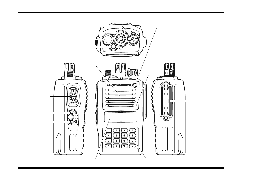
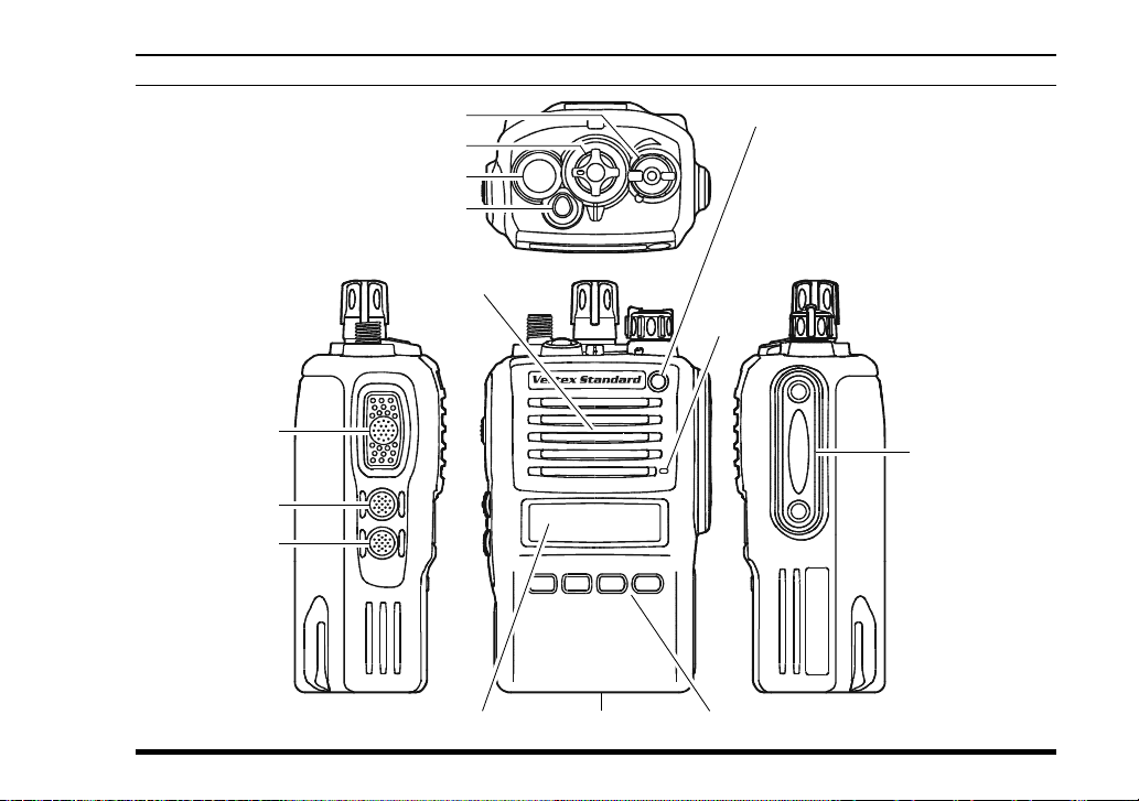
CONTROLS & CONNECTORS (16-KEY VERSION
)
PTT Switch
MONITOR Button
LAMP Button
4
VOL/PWR Knob
CH (Channel) Selector
Antenna Jack
TOP SEL Key
Speaker
LED Indicator
Steady Red:
Transmitting in progress
Blinking Green:
Busy Channel
Steady Green:
Tone Squelch in defeated condition
Dealer Programmed Color
Emergency, 5-Tone Decoded, or
2-Tone Decoded
: one of “Flashing in white,”
“Continuation changes in
Microphone
)
Battery Pack LatchLCD (Liquid Crystal Display
16-Button DTMF Keypad
sequential colors,” or “toggling the two colors.”
:
MIC/SP Jack
(
External MIC/SP
)
VX-820ATEX SERIES OPERATING MANUAL
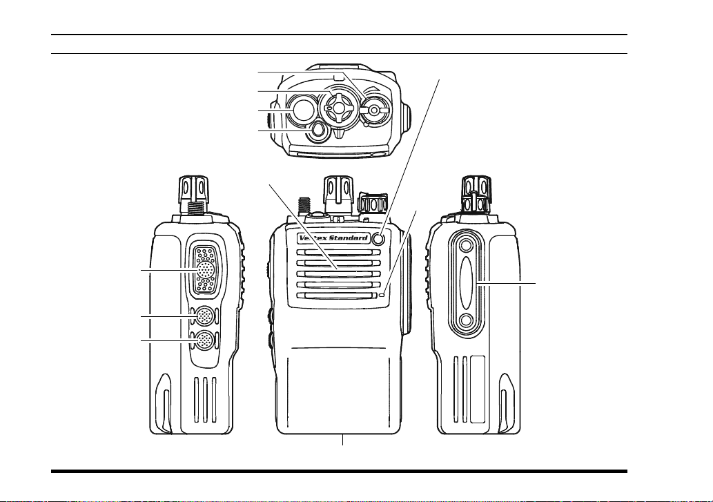
CONTROLS & CONNECTORS (4-KEY VERSION
)
VOL/PWR Knob
CH (Channel) Selector
Antenna Jack
TOP SEL Key
Speaker
PTT Switch
MONITOR Button
LAMP Button
)
VX-820ATEX SERIES OPERATING MANUAL
ABCD
Battery Pack LatchLCD (Liquid Crystal Display
LED Indicator
Steady Red:
Transmitting in progress
Blinking Green:
Busy Channel
Steady Green:
Tone Squelch in defeated condition
Dealer Programmed Color
Emergency, 5-Tone Decoded, or
2-Tone Decoded
: one of “Flashing in white,”
“Continuation changes in
Microphone
4-Button Programmable Key
sequential colors,” or “toggling the two colors.”
:
MIC/SP Jack
(
External MIC/SP
)
5
CONTROLS & CONNECTORS (NON-LCD VERSION
)
PTT Switch
MONITOR Button
LAMP Button
6
VOL/PWR Knob
CH (Channel) Selector
Antenna Jack
TOP SEL Key
Speaker
Battery Pack Latch
LED Indicator
Steady Red:
Transmitting in progress
Blinking Green:
Busy Channel
Steady Green:
Microphone
Tone Squelch in defeated condition
Dealer Programmed Color
Emergency, 5-Tone Decoded, or
2-Tone Decoded
: one of “Flashing in white,”
“Continuation changes in
sequential colors,” or “toggling the two colors.”
:
MIC/SP Jack
(
External MIC/SP
VX-820ATEX SERIES OPERATING MANUAL
)
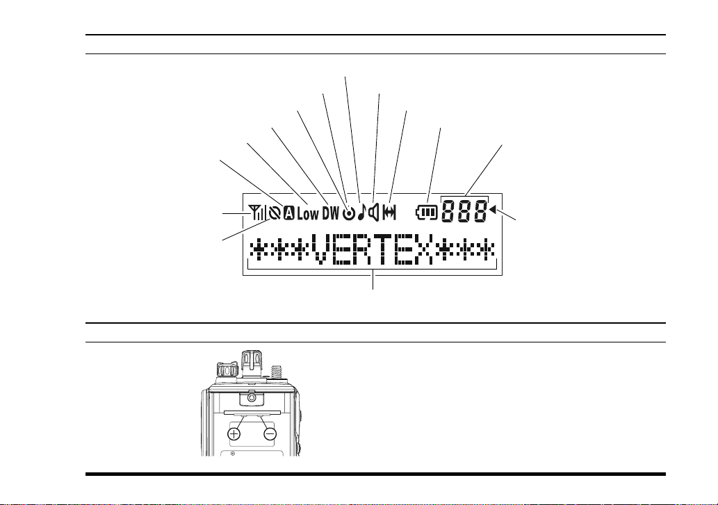
LCD ICONS & INDICATORS (16-KEY & 4-KEY VERSIONS
This channel on “SCAN” List
Priority Scan is activated
“DUAL WATCH” is activated
Low Transmit Power Mode On
Option SW (Key Function)
is activated
RSSI Indicator (four steps)
Encryption is activated
)
“CALL” Indicator
Receiver Monitor
“Talk-Around” is enabled
Battery Indicator
SUB-LCD
888: Channel Group Number
-P-: Priority Channel
-H-: Home Channel
In: ARTS “In Range”
Out: ARTS “Out of Range”
“Group Scan” is enabled
12 Character Alpha-numeric Display
BATTERY TERMINALS
Maximum Input Voltage: 8.4 V DC
Maximum Input Current:1 A
Maximum Input Power:8.4 W
Maximum Internal Capacitance: 31.4 µF
VX-820ATEX SERIES OPERATING MANUAL
7
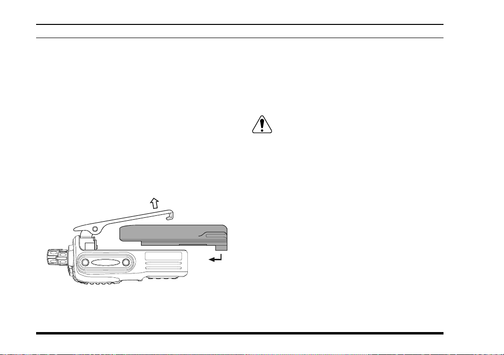
BEFORE YOU BEGIN
Battery Pack Installation and Removal
To install the battery, hold the transceiver with
your left hand, so your palm is over the speaker
and your thumb is on the top of the belt clip. Carefully mate the battery’s four insertion slots with
their corresponding alignment tabs on the transceiver case, while tilting the Belt Clip outward.
Proper alignment occurs with the battery pack
offset about 1 cm from the top edge of the battery
compartment.
Guide the pack on to the tabs with a slight inward
pressure, then slide the battery pack upward, until it locks in place with a “Click.”
Tilt the Belt Clip
Insert the Battery Pack
To remove the battery, turn the radio off and re-
move any protective cases. Slide the Battery Pack
Latch on the bottom of the radio toward the front
panel while sliding the battery down about 1 cm.
Then lift the battery out from the radio while unfolding the Belt Clip.
1) Do not remove/install the Battery Pack
in a potentially explosive atmospheres.
2) Do not attempt to open any of the rechargeable
Lithium-Ion packs, as they could explode if accidentally short-circuited.
Low Battery Indication
As the battery discharges during use, the voltage
gradually becomes lower. When the battery voltage
becomes to low, substitute a freshly charged battery
and recharge the depleted pack. The LED indicator
on the top of the radio will blink red when the battery voltage is low.
8
VX-820ATEX SERIES OPERATING MANUAL
 Loading...