

Vertex Standard VX-6000L Service Manual
VHF Low-Band FM Transceiver
VX-6000L
Service Manual
©2003 VERTEX STANDARD CO., LTD. Printed in Japan.
POWER
VERTEX STANDARD CO., LTD.
4-8-8 Nakameguro, Meguro-Ku, Tokyo 153-8644, Japan
VERTEX STANDARD
US Headquarters
10900 Walker Street, Cypress, CA 90630, U.S.A.
International Division
8350 N.W. 52nd Terrace, Suite 201, Miami, FL 33166, U.S.A.
YAESU EUROPE B.V.
P.O. Box 75525, 1118 ZN Schiphol, The Netherlands
YAESU UK LTD.
Unit 12, Sun Valley Business Park, Winnall Close
Winchester, Hampshire, SO23 0LB, U.K.
VERTEX STANDARD HK LTD.
Unit 5, 20/F., Seaview Centre, 139-141 Hoi Bun Road,
Kwun Tong, Kowloon, Hong Kong
Introduction
This manual provides technical information necessary for servicing the VX-6000L FM Transceiver.
Servicing this equipment requires expertise in handling surface-mount chip components. Attempts by non-qualified
persons to service this equipment may result in permanent damage not covered by the warranty, and may be illegal in
some countries.
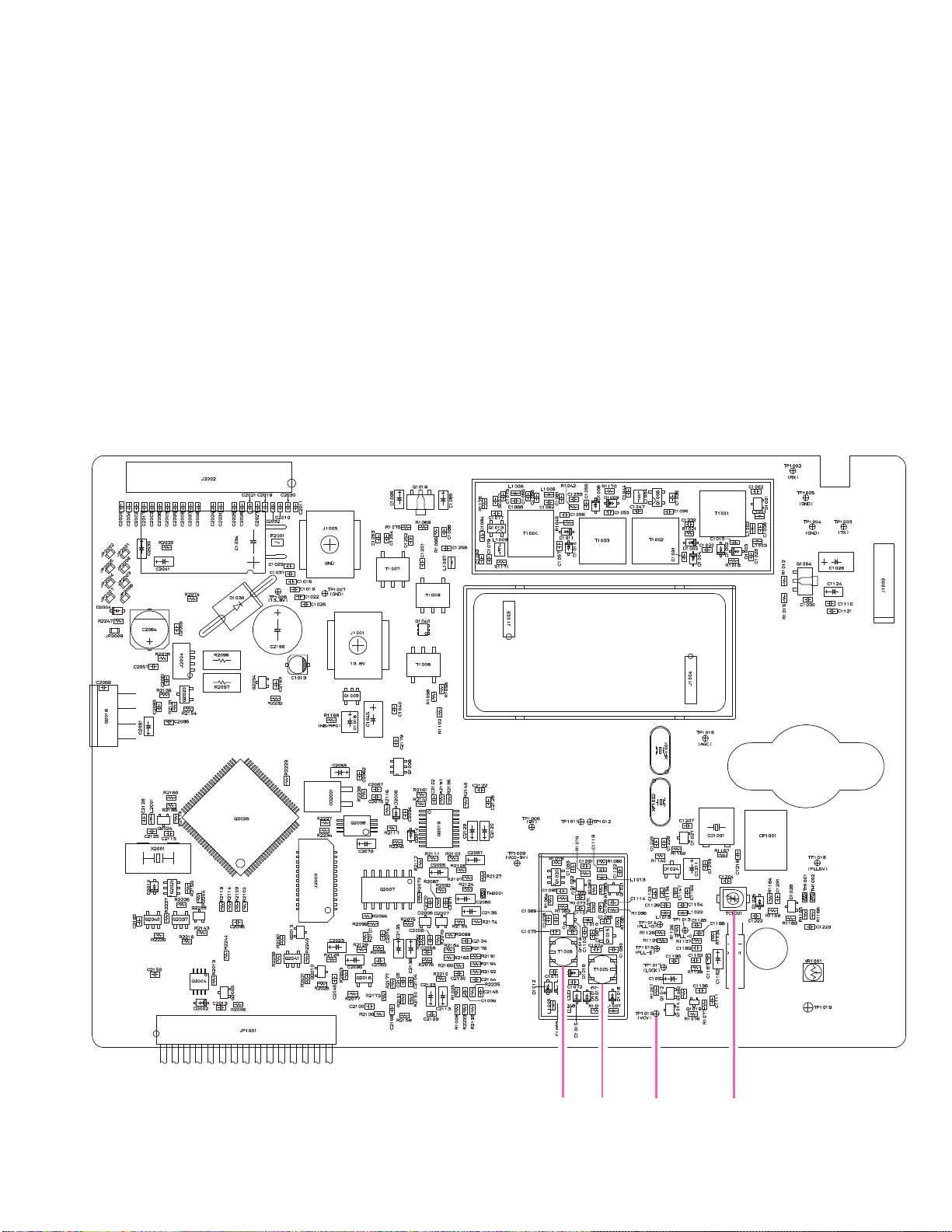
Two PCB layout diagrams are provided for each double-sided circuit board in the Transceiver. Each side of is referred
to by the type of the majority of components installed on that side (“leaded” or “chip-only”). In most cases one side has
only chip components, and the other has either a mixture of both chip and leaded components (trimmers, coils, electrolytic capacitors, ICs, etc.), or leaded components only.
While we believe the technical information in this manual to be correct, VERTEX STANDARD assumes no liability
for damage that may occur as a result of typographical or other errors that may be present. Your cooperation in pointing
out any inconsistencies in the technical information would be appreciated.
Contents
Operating Manual Reprint ........................ 1-1
Cloning ....................................................................
2-1
Specifications................................................2-2
Exploded View & Miscellaneous Parts ...3-1
Block Diagram .............................................. 3-2
Interconnection Diagram ...........................3-4
Circuit Description ..................................... 4-1
Alignment......................................................5-1
Board Unit (
MAIN Unit ........................................................... 6A-1
DISPLAY Unit ..................................................... 6B-1
KEY Unit .............................................................. 6C-1
VR Unit ................................................................. 6D-1
MIC CONN Unit ................................................. 6D-2
PA Unit ................................................................. 6E-1
NB Unit..................................................................6F-1
Optional Board Unit (
F2D-8 2-Tone Decode Unit ................................ 7A-1
VTP-50 VX-Trunk Unit ....................................... 7B-1
FVP-25 Encryption / DTMF Pager Unit ........... 7C-1
F5D-14 5-Tone Unit.............................................7D-1
FIF-7 Connection Unit ........................................ 7E-1
Schematics, Layouts & Parts
Schematics, Layouts & Parts
)
)
1
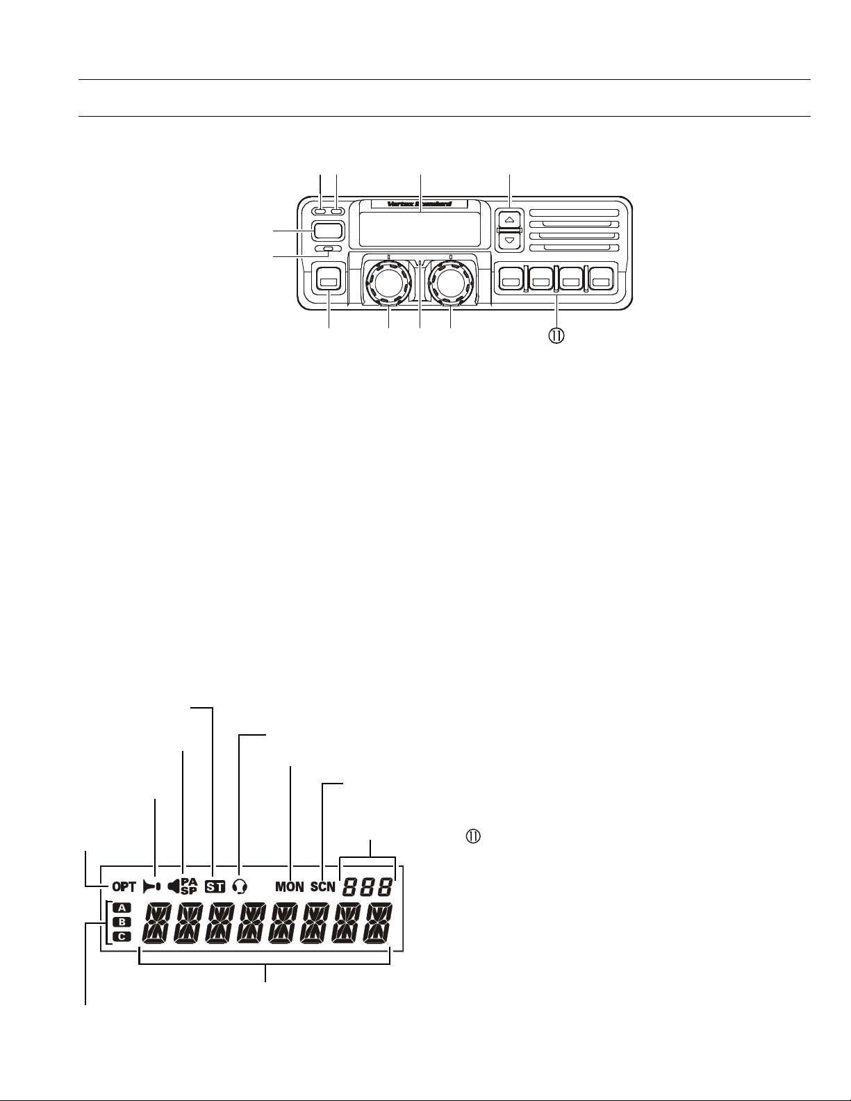
Front Panel
ƒ‚„
…
‡
ˆ‰Š
Operating Manual Reprint
CONTROLS & CONNECTORS
•
POWER
†
POWER Button
À
Press the button to turn the transceiver ON and
OFF.
TX Indicator
Á
This lamp glows red when the radio is transmit-
ting.
BUSY Indicator
Â
This lamp glows green when the channel is busy.
Liquid Crystal Display
Ã
The display include an 8-character alpha-numeric
section showing channel and group names, sta-
tus and identity information, and error messages.
Additional indicators on the display show prior-
ity channel assignments and scan include / ex-
clude selection.
This channel on
“SELECTABLE TONE” List
This channel on “PUBLIC
ADDRESS” or “SPEAKER”
List
This channel on
“HORN ALERT” List
This channel
on “OPTION”
List
This channel on “INTERCOM” List
Receiver Monitor
This channel on
“SCAN” List
Channel Group
Number
Ä p/q Button
Pressing these buttons changes the current group
(and displayed group number or name). Holding this button for more than 1/2 second causes
the function to repeat.
SQC Indicator
Å
This lamp glows orange when incorrect position
at the setting of CE49.
Programmable Function Button (PF button)
Æ
This button can be set up for special applications,
such as high/low power selection, monitor, dimmer, talk-around, and call alert function, as determined by your network requirements and programmed by your VERTEX STANDARD dealer.
VOLUME Knob
Ç
This knob sets the volume of the receiver.
EMERGENCY Microphone
È
The emergency microphone is located behind this
small slit. When the emergency feature is activated, this Microphone is enabled.
CHANNEL Selector Knob
É
This knob select the operating channel.
Programmable Function Button (PF button)
This button can be set up for special applications,
such as high/low power selection, monitor, dimmer, talk-around, and call alert function, as determined by your network requirements and programmed by your VERTEX STANDARD dealer.
8 Character Alpha-numeric Display
This channel on “AUX A/B/C” List
1-1
Operating Manual Reprint
ƒ‚•
„
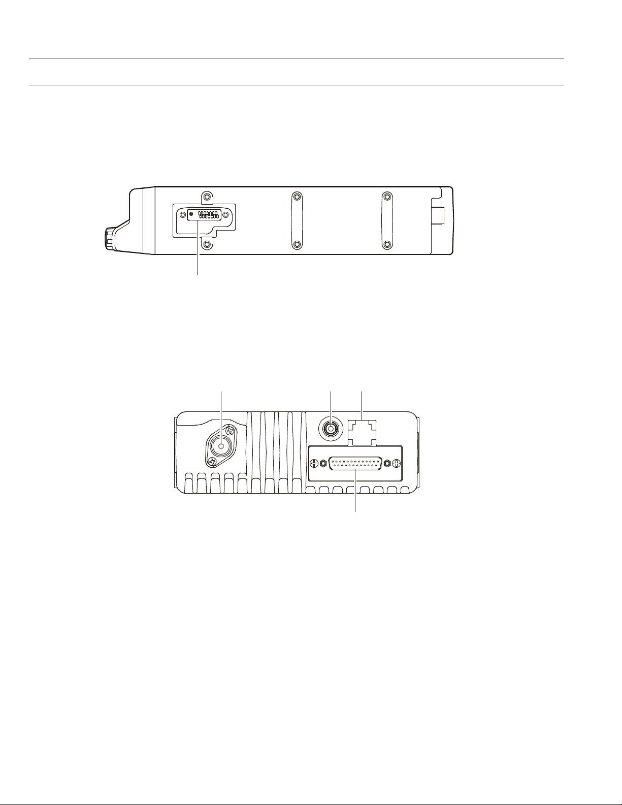
CONTROLS & CONNECTORS
Side Panel
Microphone Jack (It is on both sides.)
Connect the microphone plug to this jack.
Microphone Jack
REAR (Heatsink)
Antenna Socket
À
The 50-ohm coaxial feedline to the antenna must
be connected here, using a type-M (PL-259) plug.
External Speaker Jack
Á
An external loudspeaker may be connected to this
2-contact, 3.5-mm mini-phone jack.
Caution: Do not connect this line to ground, and be
certain that the speaker has adequate capability to handle the audio output from the
VX-6000.
13.4-V DC Power Connector
Â
The supplied DC power cable must be connected
to this 4-pin connector. Use only the supplied
fused cable, extended if necessary, for power connection.
DSUB 25-Pin Accessory Connector
Ã
External TX audio line input, PTT (Push To Talk),
Squelch, and external RX audio line output signal may be obtained from this connector for use
with accessories such as data transmission/reception modems, ets.
1-2

Operating Manual Reprint
BASIC OPERATION OF THE TRANSCEIVER
Important! - Before turning on the radio the first time,
confirm that the power connections have been made correctly and that a proper antenna is connected to the antenna jack.
Switching Power ON/OFF
Push the POWER switch turn on the radio. The
display will become illuminated. The radio will
start up on the last channel used prior to shut-
down during the previous operating session.
Turn the CHANNEL selector knob to choose the
desired operating channel. A channel name will
appear on the display. If you want to select the
operating channel from a different Memory
Channel Group, press the UP (p) or DOWN (q)
button to select the Memory Channel Group you
want before selecting the operating channel.
Setting the Volume
Turn the VOLUME knob clockwise to increase the
volume, and counterclockwise to decrease it. If
no signal is present, press and hold in the MON
button more than 1/2 seconds; background noise
will now be heard, and you may use this to set
the VOLUME knob for the desired audio level.
Press and hold the MON button more than 1/2
seconds to quiet the noise and resume normal
(quiet) monitoring.
Transmitting
To transmit, wait until the “BUSY” indicator is
off (the channel is not in use), and press the PTT
(Push-To-Talk) switch on the side of the micro-
phone (the “TX” indicator will appear or the “TX”
indicator will glow red). While holding in the PTT
switch, speak across the face of the microphone
in a clear, normal voice level, and then release
the PTT switch to receive.
Selecting Groups and Channels
m Press the UP (p) or DOWN (q) button (re-
peatedly, if necessary) to select a different
group of channels.
m Turn the CHANNEL selector knob to select a
different channel within the current group.
Automatic Time-Out Timer
If the selected channel has been programmed for
automatic time-out, you must limit the length of
each transmission. While transmitting, a beep will
sound five seconds before time-out. Another beep
will sound just before the deadline; the “TX” in-
dicator will disappear and transmission will cease
soon thereafter. To resume transmitting, you must
release the PTT and wait for the “penalty timer”
to expire (if you press the PTT before this timer
expires, the timer restarts, and you will have to
wait another “penalty” period.)
1-3
Operating Manual Reprint
ADVANCED OPERATION
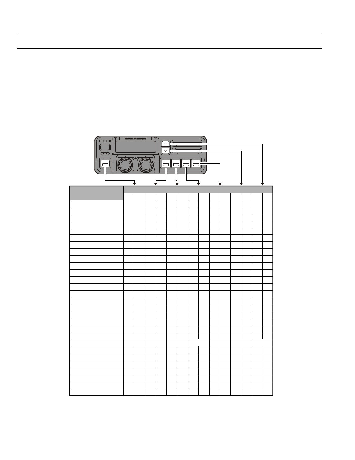
Programmable Function Button (PF button)
The VX-6000 includes the seven Programmable
Function Buttons (PF button). The PF button
functions can be customized, via programming
by your VERTEX STANDARD dealer, to meet
your communications/network requirements.
Some features may require the purchase and installation of optional internal accessories. The
possible PF button programming features are il-
POWER
Functions
None
SCAN (SCN)
Dual Watch
Call/Reset
Talk-Around (TA)
Noise Blanker* (NB)
Alpha Numeric (A/N)
DIMMER (DIM)
Emergency (EMG)
Horn Alert (HA)
Home Channel (HOM)
Intercom (IC)
Low Power (LOW)
GRP UP
GRP DWN
CH UP
CH DWN
AUX A
AUX B
AUX C
Public Address (PA)
Monitor (MON)
RCL
Selectable Tone (ST)
SP**
Squelch Level (SQL)
Compander
Encryption*** (OPT)
* for VX-6000L ** requires RMK-4000 *** requires Encryption Unit
<1.5 sec >1.5 sec <1.5 sec >1.5 sec <1.5 sec >1.5 sec <1.5 sec >1.5 sec <1.5 sec >1.5 sec <1.5 sec >1.5 sec <1.5 sec >1.5 sec
Programmable Function Button (PF button)
lustrated at the below, and their functions are
explained on next page.
For further details, contact your VERTEX STANDARD dealer. For future reference, check the box
next to each function that has been assigned to
the PF button on your particular radio, and keep
it handy.
1-4

Operating Manual Reprint
ADVANCED OPERATION
Channel Scan
The Scanning feature is used to monitor multiple
signals programmed into the transceiver. While
scanning, the transceiver will check each chan-
nel for the presence of a signal, and will stop on a
channel if a signal is present.
To activate scanning:
m Press the assigned PF button of the “Scan” mo-
mentarily to activate scanning.
m The scanner will search the channels, looking
for active ones; it will pause each time it finds
a channel on which someone is speaking.
To stop scanning
m Press the assigned PF button of the “Scan”.
m Operation will revert to the channel to which
the CHANNEL selector knob is set.
Note:Your dealer may have programmed your
radio to stay on one of the following chan-
nels if you press the PTT switch during
scanning pause:
Current channel (“Talk Back”)
r
“Last Busy” channel
r
“Priority” channel
r
“Home” channel
r
Scan Start” channel
r
Dual Watch
The Dual Watch feature is similar to the Scan fea-
ture, except that only two channels are monitored:
r The current operating channel; and
r The “Priority” channel.
To activate Dual Watch:
m Press the assigned PF button of the “Dual
Watch”.
m The scanner will search the two channels; it
will pause each time it finds a channel on
which someone is speaking.
To stop Dual Watch:
m Press the assigned PF button of the “Dual
Watch”.
m Operation will revert to the channel to which
the CHANNEL selector knob is set.
ARTS (Auto Range Transpond System)
This system is designed to inform you when you
and another ARTS-equipped station are within
communication range.
During ARTS operation, your radio automatically
transmits for about 1 second every 25 (or 55) seconds (the interval is programmed by Dealer) in
an attempt to Shake hands with the other station.
If you move out of range for more than one minutes, your radio senses that no signal has been
received, a ringing beeper will sound. If you subsequently move back into range, as soon as the
other station transmits, your beeper will sound.
The PF Button Function
The PF (Programmable Function) button can be
programmed by the dealer to provide two of the
other functions described below.
To activate the primary Accessory function, press
the PF button momentarily. To access the second-
ary Accessory function (which may include the
Alarm), press and hold the PF button for 1.5 sec-
onds or longer.
Call/Reset
When this feature is programmed and a selective call has been received, momentarily press the
assigned PF button of the “Call/Reset” to reset
the flashing indicator and mute the receiver, oth-
erwise press the assigned PF button of the “Call/
Reset” to sent your radio’s identification code
(ANI) to the dispatcher.
Talk-Around
The feature causes the assigned PF button of the
“Talk-Around” to select simplex operation on
semi-duplex channels: the transmit frequency
becomes the same as the receive frequency (regardless of any programmed offset for the channel).
Note:This feature has no effect on simplex channels.
After pressing the button, “-TAKARD-” is displayed
on the LCD.
Noise Blanker (for VX-6000L)
Because local noise can be particularly troublesome in the VHF Low-Band frequency spectrum,
the Low-Band version of the VX-6000 includes a
Noise Blanker feature, which may be toggled on
and off by pressing the assigned PF button of the
“Noise Blanker” for the appropriate length of
time.
1-5

Operating Manual Reprint
ADVANCED OPERATION
Alpha Numeric
Press the assigned PF button of the “Alpha Nu-
meric” to switch the display between the Group/
Channel number, and the Group/Channel name
(alphanumeric). A tone will sound each time you
switch between numerical and alphanumerical
display.
DIM
Press the assigned PF button of the “DIM” to ad-
just the brightness of the display and key
backright.
EMG (Emergency)
Press the assigned PF button of the “EMG” to
initiate an emergency call (requires ANI board).
When an emergency call is made, not tone is
emitted and the display does not change. To end
the emergency call, turn the transceiver power
OFF.
HA (Horn Alert)
Press the assigned PF button of the “HA” to turn
the Horn Alert function ON or OFF. If you receive a call from the base station with 2Tone or
DTMF signaling, horn alert will activate.
When you turn Horn Alert ON, a tone will sound
and “ ” appears on the display..
Home (Home Channel)
Press the assigned PF button of the “Home” to
select the pre-programmed Home Channel. Press
it again to return to the previous channel. If used
while scanning, pressing this key a second time
will change to the revert channel.
IC (Intercom)
This feature requires dual head configuration.
Press the assigned PF button of the “IC” to turn
the intercom feature ON or OFF. While ON, you
can press the PTT switch to communicate to another control head operator without transmitting
over the air. When you press this key, a tone
sounds and “ ” appears on the display. The intercom can be used even while scanning and receiving a call.
GRP UP/DWN
Press the assigned PF button of the “GRP UP”
or “GRP DWN” to select a different group of
channels.
CH UP/DWN
Press the assigned PF button of the “CH UP” or
“CH DWN” to select a different channel within
the current group.
AUX A/B/C
Press the assigned PF button of the “AUX A”,
“AUX B”, or “AUX C” to turn the output port (respectively).
PA (Public Address)
Press the assigned PF button of the “PA” to use
the transceiver as a PA amplifier. When you enable this function, a tone sounds and “ ” appears on the display. The public address can be
used even while scanning and receiving a call.
MONI (Monitor)
Press the assigned PF button of the “MONI” mo-
mentarily to cancel CTCSS and DCS signaling
squelch; the “MON” icon appears on the display.
Press and hold this key for 1/2 seconds to hear
background noise (unmute the audio); the MON
icon blinks on the display.
RCL (Channel Recall)
During scan, you can press the assigned PF but-
ton of the “RCL” to select the last called channel.
ST (Selectable Tone)
Press the assigned PF button of the “Selectable
Tone”, then rotate the CHANNEL selector knob
to select a 2-Tone.
SP
Press the assigned PF button of the “SP” to switch
“Front panel”, “Front panel & Body” and “Body”
speaker. When “Body” is selected, a tone sounds
and the “ ” icon appears on the display. You
can use this function while scanning and receiving a call. However, all audio will be emitted from
the PA speaker.
Low Power
Press the assigned PF button of the “Low Power”
to set the radio's transmitter to the “Low Power”
mode.
Press this key again to return to “High Power”
operation when in difficult terrain.
1-6

ADVANCED OPERATION
SQL (Squelch Level)
You can manually adjust the squelch level using
this function:
1. Press the assigned PF button of the “SQL”. A
tone sounds and SQL appears on the display
with the current squelch level.
2. Rotate the CHANNEL selector knob to select
the desired level.
3. Press the this key. A tone sounds and the display returns to the normal channel.
COMP (Compander)
Press the PF button assigned to the “COMP”
function to turn the “Compander” IC ON or OFF.
This IC contains two variable gain circuits configured for compressing and expanding the dynamic range of the radio's transmitted audio signal.
When you enable this function, the signal-to-noise
radio can be improved by reducing the transmitted audio dynamic range.
Encryption (Option)
When the Voice Scrambler feature is enabled,
pressing the assigned PF button of the “Encryp-
tion” toggles the Scrambler on and off.
1-7

Operating Manual Reprint
OPTIONAL ACCESSORIES
MH-25
MH-53
MH-53
MH-53
CE49 Programming Software
CT-70 Radio Programming Cable (Requires VPL-1)
CT-71 Radio to PC Programming Cable
CT-72 Radio to Radio Programming Cable
CT-81 Cable for RMK-4000 (6 m)
CT-82 Cable for RMK-4000 (2.5 m)
CT-83 Cable for RMK-4000 (0.6 m)
CNT-6000 Control Head
RF DECK RF Deck w/MMB-79 (for Dual Band Installations)
RMK-4000SH Remote Kit (for Single Transceiver)
RMK-4000DH Remote Kit (for Dual-Head Installations)
RMK-4000DB Remote Kit (for Dual Band Installations)
RMK-4000DBH Remote Kit (for Dual Band plus Dual Head Installations)
F2D-8 2-Tone Decode Unit (Requires FIF-7)
F5D-14 5-Tone ENC-DEC Unit (Requires FIF-7)
VTP-50 VX-Trunk Unit (Requires FIF-7)
FVP-25 Band inversion scrambler/DTMF paging Unit (Requires FIF-7)
FVP-35 Encryption Unit (Rolling code voice scrambler; Requires FIF-7)
MDC1200 Digital ANI encoder Unit (Requires FIF-7)
FP-1023 External 23A Power Supply
MLS-100 Mobile Loud speaker (12 W Peak Power)
MMB-79 Mobile Mounting Bracket
MMB-77 Locking Mobile Mounting Bracket
FIF-7 Inter face Board (for F2D-8, F5D-14, VTP-50, FVP-25)
CN-6 Inter face Board (for Accessories)
B7A
C7A
A7A
B7A
Microphone
Heavy Duty Microphone
Heavy Duty Microphone w/Noise Canceler
Heavy Duty DTMF Microphone w/Noise Canceler
1-8
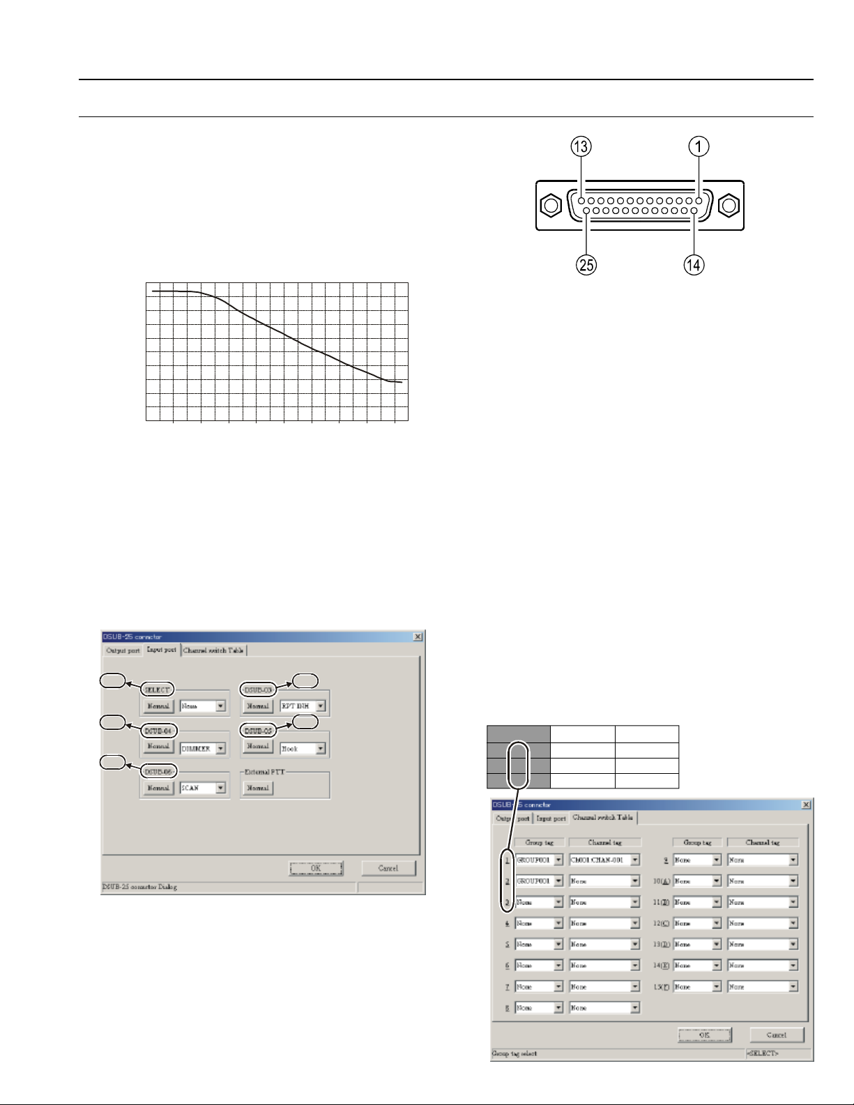
DSUB 25-PIN ACCESSORY CONNECTOR
DSUB25 output level (V)
5.0
4.5
4.0
3.5
3.0
2.5
2.0
1.5
1.0
0.5
0.125
Pin 1: RSSI [Analog Output]
A DC voltage proportional to the strength of the
signal currently being received (Receiver Signal
Strength Indicator) is provided on this pin. This
low impedance output is generated by the receiver IF sub-system and buffered by an internal
op-amp. Typical voltages are graphed as follows:
0
1259 398 125 398 12.5 4 1.25 0.4
SSG Input Level (uV)
Pin 2, 3, 4, 5 & 6: SELECT, DSUB 03, DSUB 04,
DSUB 05 & DSUB 06
[Digital Input Port]
These input port features can be programmed via
the CE49 programmer. The same item can not be
chosen twice.
To select the “Input port” page, (Common à
DSUB-25 à Input port).
Pin 2
Pin 4
Pin 6
Pin 3
Pin 5
0.04
Operating Manual Reprint
DSUB 25-Pin Numbering
None
MON This feature is the same as pressing
and holding in the Monitor key.
DIMMERLCD illumination dimmer “on.”
Hook Activates the Hook1 feature.
SCAN Activates the scanner.
G-SCAN Activates the Group scanner.
RPT INH Disables the repeater feature during
Multi Deck operation.
EMG Activates the Emergency feature.
Home Switches to the Home Channel.
CH SW0 Memory channel recall
(Channel Switch Table bit 0)
CH SW1 Memory channel recall
(Channel Switch Table bit 1)
CH SW2 Memory channel recall
(Channel Switch Table bit 2)
CH SW3 Memory channel recall
(Channel Switch Table bit 3)
Example
If you assign “CH SW0” and “CH SW1” to the
Universal Input Port, you can recall Channels 1~3
as shown below.
Channel CH SW0 CH SW1
1 1 0
2 0 1
3 1 1
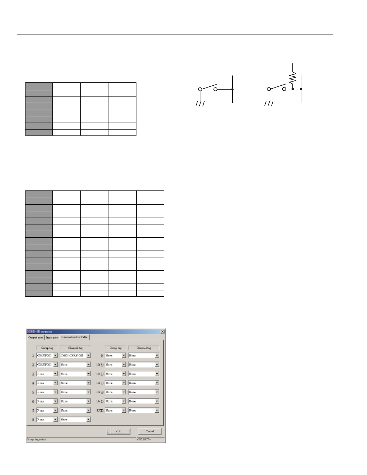
LOGIC level (+5V / 0V) input (Low active).
High Impedance input.
1-9
Operating Manual Reprint
DSUB 25-Pin
5V
DSUB 25-PIN ACCESSORY CONNECTOR
Similarly, if you assign “CH SW0,” “CH SW1,”
and “CH SW2” to the Universal Input Port, you
can recall Channels 1~7 as shown below:
Channel CH SW0 CH SW1 CH SW2
1 1 0 0
2 0 1 0
3 1 1 0
4 0 0 1
5 1 0 1
6 0 1 1
7 1 1 1
If you need to recall all memory channels (15 CH)
from the External Controller via the Uni-versal
Input Port, you should assign the “All Channel
Recall” Command (CH SW 0 ~ CH SW 3) to the
Universal Input Port.
In this case:
Channel CH SW0 CH SW1 CH SW2 CH SW3
1 1 0 0 0
2 0 1 0 0
3 1 1 0 0
4 0 0 1 0
5 1 0 1 0
6 0 1 1 0
7 1 1 1 0
8 0 0 0 1
9 1 0 0 1
10 0 1 0 1
11 1 1 0 1
12 0 0 1 1
13 1 0 1 1
14 0 1 1 1
15 1 1 1 1
The Memory Channel is determined via the CE49
Programmer. (Common à DSUB-25pin connector à Channel switch Table).
47k
W
DSUB 25-Pin
PINS 2, 3, 4, 6
PIN 5 (Pull Up)
Sample Circuit
Pin 7: E [GND]
Ground for all logic levels and power supply return.
Pin 8: A KEY OUT [Universal Output Port]
Open collector output. Output voltage 0 ~ 5 V,
Max. sink current 30 mA.
The possible programming features (use CE49)
are illustrated below.
A PORT/B PORT/C PORT/D PORT/E PORT/
None
Refer to the “Pins 20, 21, & 22” section for details.
Pin 9: TXD [Digital Output for Alignment software]
Connect to the RS232C cable (requires FIF-8 and
CT-88)
Pin 10: RXD [Digital Input for Alignment software]
Connect to the RS232C cable (requires FIF-8 and
CT-88)
Pin 11: EXT PTT
Shorting this port to ground causes the transceiver to be placed in the Transmit mode, while
opening the connection to this port returns the
transceiver to the Receive mode.
1-10
Pin 12: MIC MUTE
MIC mute on: Level High (5V)
MIC mute off: Open
LOGIC level (+5V / 0V) output.
When the PTT/EXT PTT switch is pressed, this
pin switches to “open.”

Operating Manual Reprint
DSUB 25-Pin
DSUB 25-PIN ACCESSORY CONNECTOR
Pin 13: TXDI [Digital Input for DATA Communications]
m TX Hi-speed Data Input Type (jumper JP2005).
Input level 800 mV/600 Ohms, Max.input 1.2V
m Tx Low-speed Data input Type (Jumper
JP2006). Input level 40 mV/600-Ohms
If the Jumper setting is “Low-speed Data” (JP2006
jumpered), this port is usable in the AUDIO
(300~3000 Hz) range.
If the jumper setting is “HI-speed Data” (JP2005
jumpered), this port is usable for 9600 bps DATA
communications, because the filter and limiter are
not engaged in the Audio line.
Pin 14: DC OUT [13.4 V/5 V DC Output]
m Switched 13.8V output for supplying power
to an accessory (jumper JP2008).
m Switched and regulated DC 5.0V output for
supplying power to an accessory (jumper
JP2007).
Maximum output current is 200 mA
Pin 15: IGN [Ignition Sense feature]
The VX-6000 may automatically be switched to
the STAND-BY mode when the vehicle's igni-tion
key is turned on.
Maximum current is 20 mA.
This feature is only enabled on transceivers configured for Dual Deck operation.
Pin 17: RX DO [Digital Output for DATA Communica-
tions]
m RX Hi-speed Data Output Type (jumper
JP2003). output level 600 mV/10k Ohms
m RX Low-speed Data Output Type (jumper
JP2004). output level 200 mV/600 Ohms
If the Jumper setting is “Low-speed Data” (JP2004
jumpered), this port is usable in the AUDIO
(300~3000 Hz) range.
If the jumper setting is “HI-speed Data” (JP2003
jumpered), this port is usable for 9600 bps DATA
communications, because the filter and limiter are
not engaged in the Audio line.
Pin 18: E [GND]
Ground for all logic levels and power supply return.
Pins 19, 20, 21, & 22: DSUB 19, DSUB 20, DSUB 21
and DSUB 22
[Universal Output Port]
LOGIC level (+5V / 0V) output.
The logic output appears at these pins when the
front panel's PF key is turned on.
The possible programming features (use CE49)
are illustrated below.
If the HA feature is assigned to these ports, a current amplifier must be connected between the
Horn circuit and the port.
Ignition 13.8V
Pin 16: NC [NO connection]
None/A PORT/B PORT/C PORT/D PORT/E
PORT/HA PORT
Pin 23: EXT SQL [Squelch Signal Output]
Open collector output. Max. sink current 10 mA.
A Signal is present (Squelch is open): Level High
No Signal is present (Squelch is closed): Open
When you connect the solder jumper on J2002,
this port changes to PULL UP (5 V) output.
This status can be changed by CE49 programmer.
Pin 24: SP MUTE [Speaker Mute Output]
Open collector output.
External Speaker mute on: Level High
External Speaker mute off: Open
Pin 25: E [GND]
Chassis ground.
1-11

Operating Manual Reprint
Note:
1-12
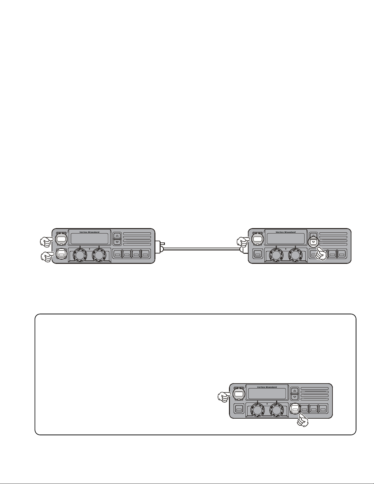
Cloning
The VX-6000 includes a convenient “Clone” feature,
which allows the programming data from one trans-
ceiver to be transferred to another VX-6000. Here is
the procedure for Cloning one radio’s data to another.
Note: When a cloning isn't made, you correct the following part using "CE49."
When a "Radio to Radio Clone" which is in the
"Miscellaneous" menu is "Disabled," change this
menu to "Enabled."
1. Turn both transceivers off.
2. Remove the plastic cap and its two mounting
screws from the MIC/SP jack on the transceiv-
er. Do this for both transceivers.
3. Connect the optional CT-72 cloning cable between the MIC/SP jacks of the two transceivers.
4. On the Destination transceiver, press and hold
the PF Button (just below the POWER Button)
while turning the transceiver on.
5. Now, on the source transceiver, press and hold
the q Button while turning the transceiver
on.Data will now be transferred to the Destina-
tion transceiver from the source transceiver.
6. If there is a problem during the cloning process,
sound an error beep from source the transceiver.
Check your cable connections and battery voltage, and try again.
7. If cloning is a successful, turn the Destination
transceiver off. Now turn the source transceiver off.
8. Disconnect the CT-72. Replace the plastic cap
and its two mounting screws.
9. You can then turn the transceivers back on, and
begin normal operation.
Optional Cloning Cable
CT-72
POWERPOWER
Destination source
DealerProgramming of VTP-50 and F5D-14
These procedures are designed to be used by the installing technician after the VTP-50 and F5D-14 has
been installed in the transceiver. To program a VX-6000's VTP-50 and F5D-14 board, you will need the
CT-71 programming interface cable, the CE-26 Programming diskette, and an IBM PC/AT or PS/2-
compatible type computer.
To enter the Programming mode, use the following procedure:
1. Turn the transceiver off.
2. Turn on the transceiver while holding in the
PF Button (just below the q Button).
POWER
2-1

Specifications
GENERAL
Number of Channels: 250 channels
Frequency Range: 37.0 - 50 MHz
Channel Spacing: 5 / 10 / 12.5 / 15 / 20 / 25 / 50 kHz
Power Supply Voltage: 13.4 VDC
Current Consumption: Standby: 500 mA
Receive: 2.5 A
Transmit: 22 A
Ambient Temperature Range: –22°F to +140°F (–30°C to +60°C)
Frequency Stability: Better than ±5.0 ppm
RF Input-Output Impedance: 50 Ohms
Audio Output Impedance: 4 Ohms
Dimensions: 7" (w) x 2.4" (H)x 11.9" (D) (178 x 60 x 301 mm)
Weight: 15.4 lbs. (7.0 kg)
RECEIVER (Measurements made per EIA standard TIA/EIA-603)
Circuit Type: Double-conversion Super-heterodyne
Sensitivity(EIA 12 dB SINAD): 0.25 µV
Adjacent Channel Selectivity: 85 dB
Intermodulation: 80 dB
Spurious and Image Rejection: 85 dB
Audio Response: +3 / –8 dB from the 6 dB / oct. re-emphasis curve
Audio Output: 5 W @ 4 Ohms, 10 % THD
10 W @ 4 Ohms w/<10 % THD (Option)
TRANSMITTER (Measurements made per EIA standard TIA/EIA-603)
Power Output: 120 / 50 W
Modulation: 16K0F3E, 11K0F3E
Max Deviation: 5.0 kHz
Conducted Spurious Emissions: 70 dB Below Carrier
FM Hum & Noise: 45 dB (25 kHz)
Audio Response: +1 / –3 dB from the 6 dB / oct-8
Audio Distortion (@ 1 kHz): < 5 %
Measurements per EIA standards unless noted above.
Specifications subject to change without notice or obligation.
2-2
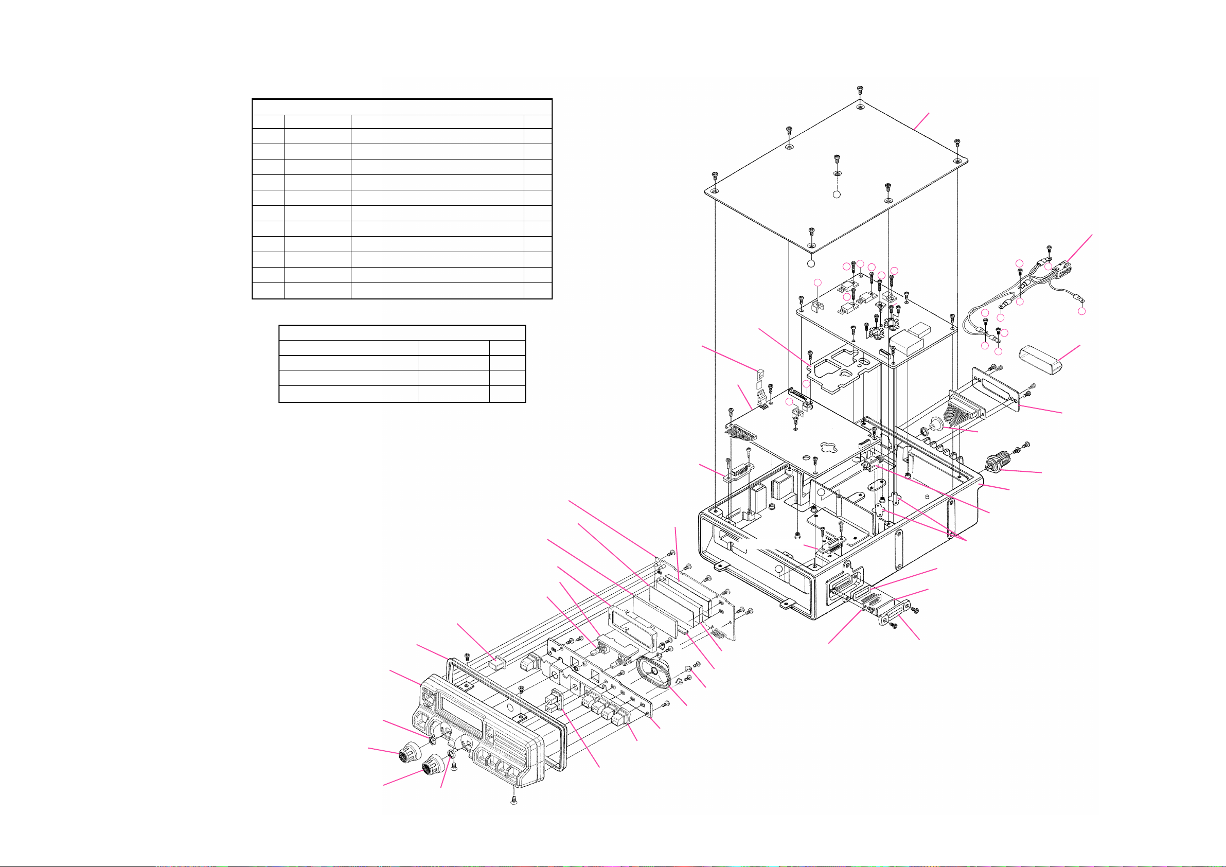
Exploded View & Miscellaneous Parts
À
Screw List
REF. VXSTD P/N Description Qty.
1 U20306007 BINDING HEAD SCREW M3x6B 7
2 U20306002 BINDING HEAD SCREW M3x6NI 6
3 U24308002 TAPTITE SCREW M3x8NI 17
4 U23206001 TAPTITE SCREW M2.6x6 14
5 U20305007 BINDING HEAD SCREW M3x5B 2
6 U32450007 FLAT HEAD SCREW M2.6x5B 2
7 U31306007 OVAL HEAD SCREW M3x6B 2
8 U02308002 SEMS SCREW SM3x8NI 4
9 S5000182 SCREW JFS-4S-B1MW 2
10 U04306002 SEMS SCREW HSM3x6NI 3
11 U20312002 BINDING HEAD SCREW M3x12NI 5
Accessories
Description VXSTD P/N Qty.
DC CABLE 04P 40AX2 T9023140 1
KNOB CAP RA0254100 5
NAME PLATE RA0254700 1
DISPLAY Unit
RA0252800
DIFFUSER SHEET
G6090140
LCD
RA0253000
LCD HOLDER
VR Unit
VR3601*
RA0254000
RUBBER KNOB (PWR)
RA0254200
RUBBER PACKING
RA0378900
PANEL ASSY
Á
Á
Supplide is VR3601*
RA02543A0
KNOB
Æ
RA0254300
KNOB
R6054387B
SPECIAL NUT
Æ
RA0252700
REFLECTOR SHEET
Ã
Ã
Ã
RA0275500
RUBBER KNOB ASSY
R0134490
HOLDER
MIC CONN Unit
Ã
Ã
Ã
Ã
Ã
Ã
Ã
Ã
M4090133
SPEAKER
KEY Unit
RA0253900
RUBBER KNOB (CH)
À
RA0445900
HEATSINK PLATE
MAIN Unit
Â
Â
Â
Â
MIC CONN Unit
Ã
Ã
Ã
RA0252300
LIGHT GUIDE
RA0252900
RUBBER CONNECTOR
R0145680
FITTING (x4 pcs)
À
À
A
À
B
Â
11
D
11
Ç
Â
Â
E
F
Â
Â
A
Â
Â
B
RA025480A
CONTACT ASSY (Both Side)
Non-designated parts are available only as part of a
designated assembly.
C
Â
Å
Ç
Â
RA0332800
CASE
À
À
T9206926
WIRE ASSY
Â
10
11
11
11
C
Â
D
D
10
E
C
S6000395
COVER P-25P(23)
È
Â
Ç
Ç
Â
10
F
Á
È
Á
RA0262300
S6000396
*A
RA020830A
DOUBLE FACE (Both Side)
RA0215400
SHEET
RUBBER GROMMET TM-96-17
P1090654
CONNECTOR
(W/ *A)
RA0446000
HEATSINK PLATE
Á
Á
RA0445800
CHASSIS
HOLDER PLATE
P1090984
CONNECTOR
Ä
Ä
RA0215000
EXT CAP
3-1
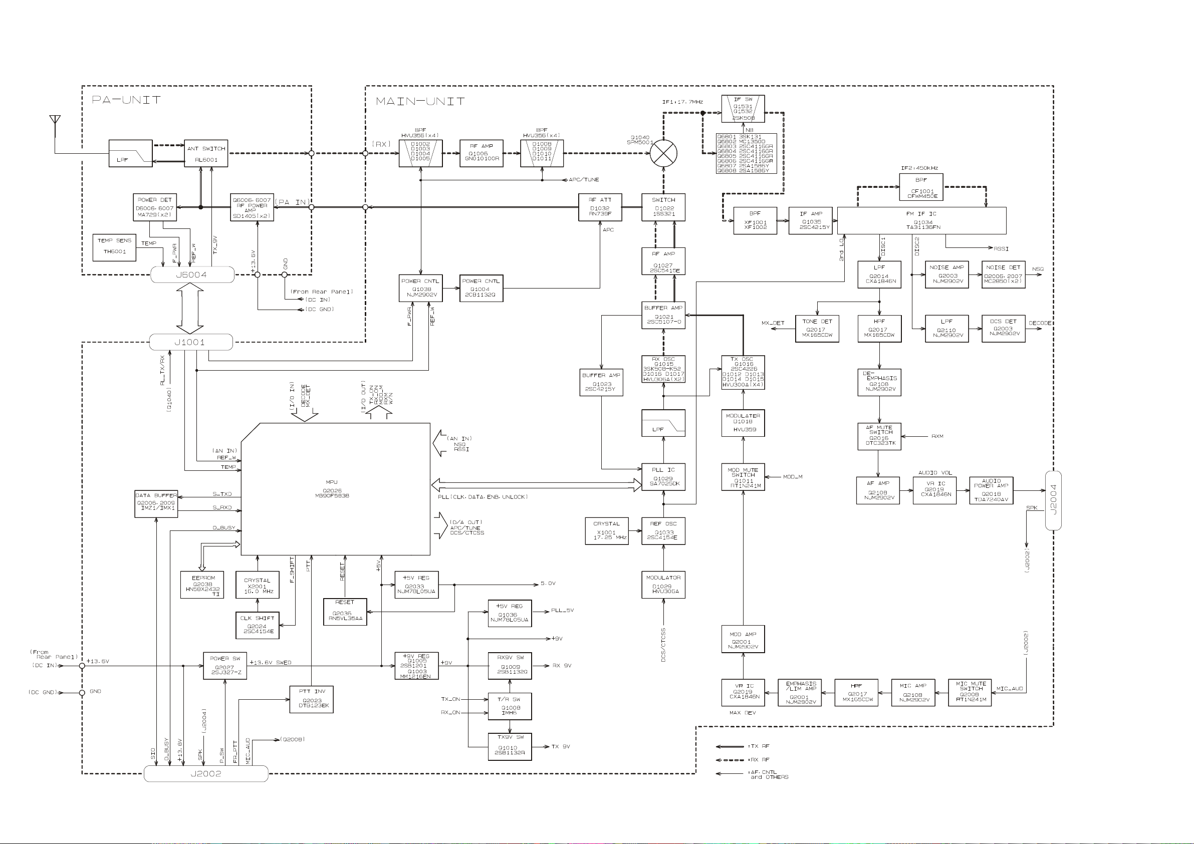
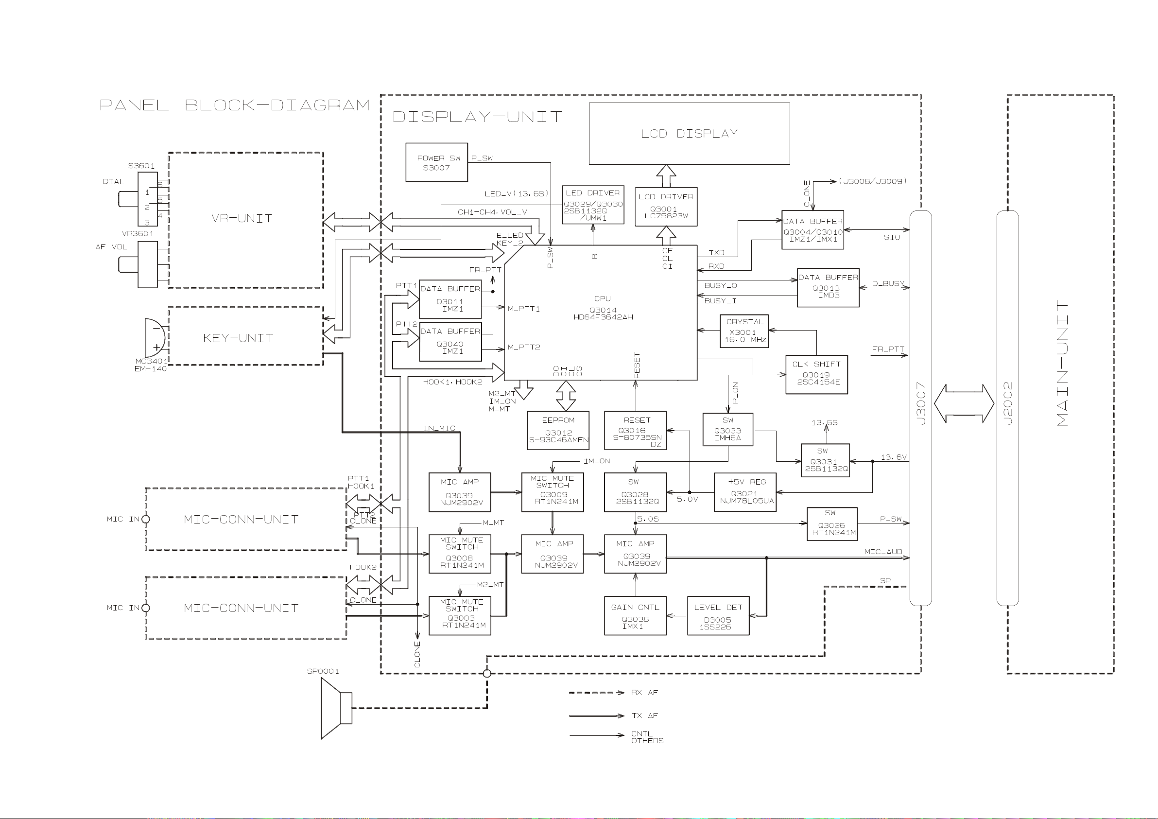
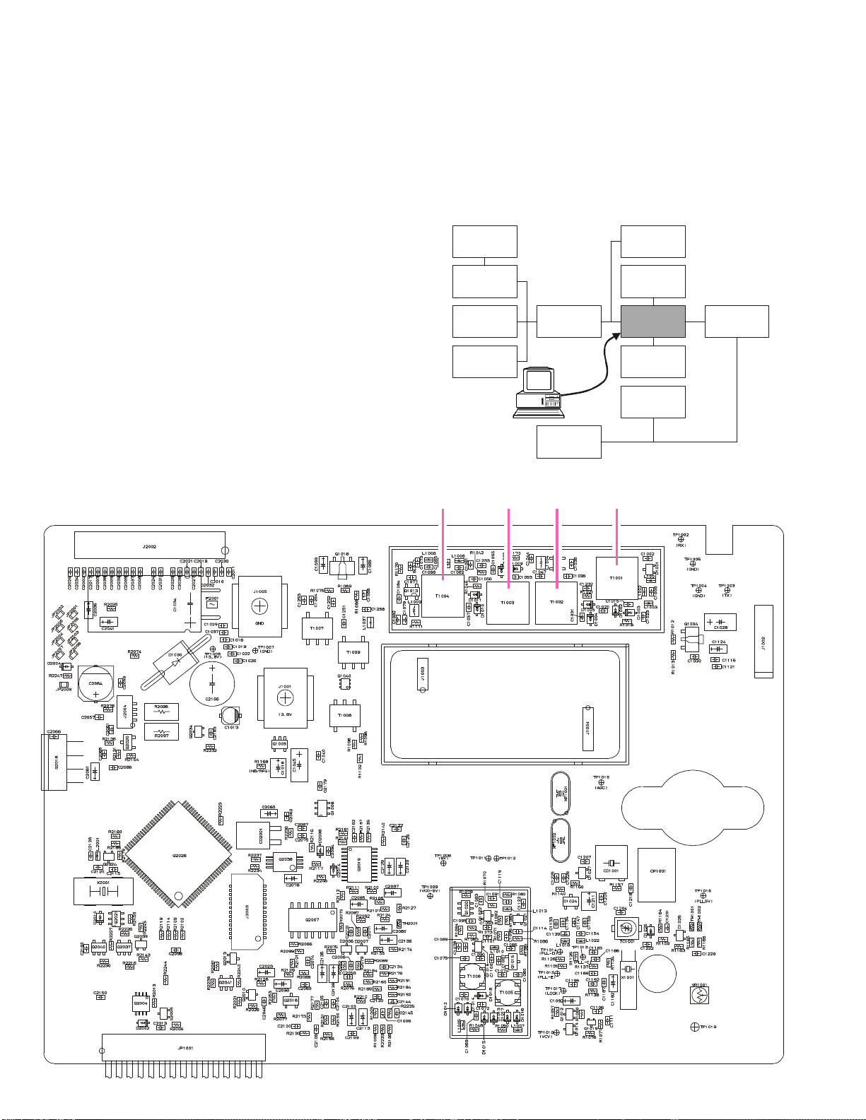
Block Diagram
3-2
Block Diagram
3-3
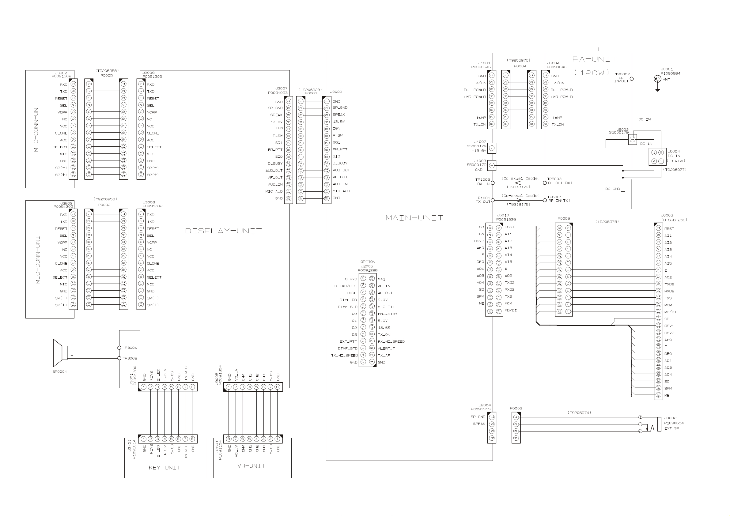
Interconnection Diagram
3-4

Circuit Description
Transceiver functions, such as PLL synthesizer
settings and channel programming, are controlled
via the microprocessor unit (MPU). Reception and
transmission are switched by "RX" and "TX" lines,
also controlled from the MPU.
Signal Path Overview
The receiver uses double-conversion superheterodyne circuitry, with a 17.7 MHz 1st IF and 450
kHz 2nd IF. The 1st LO, produced by a PLL synthesizer, yields the 17.7 MHz 1st IF. The 2nd LO uses a
17.25 MHz (17.7 MHz - 450 kHz) signal generated
by a crystal oscillator. The 2nd mixer and other circuits use a custom IC to convert and amplify the 2nd
IF, and detect FM to obtain demodulated signals.
During transmit, the PLL synthesizer oscillates at
the desired frequency directly, for amplification to
obtain RF power output. During transmit, voice
modulation and CTCSS (or DCS) modulation are
applied to this synthesizer. Transceiver functions,
such as TX/RX control, PLL synthesizer settings, and
channel programming, are controlled using the
MPU.
Receiver
Incoming RF signals from the antenna connector
are delivered to the PA Unit, and pass through a
low-pass filter (LPF) network consisting of coils
L6011, L6010, and L6009, capacitors C6047, C6045,
C6044, C6075, C6043, C6042 and C6074, and antenna switching relay RL6001 for delivery to the receiver
front end in the MAIN Unit.
Signals within the frequency range of the transceiver are then passed through a varactor-tuned
band-pass filter consisting of T1001/T1002/T1003 and
T1004 before RF amplification by Q1006
(GN010100R).
The amplified RF is then band-pass filtered again
by varactor-tuned resonators T1001, T1002, T1003
and T1004 to ensure pure in-band input to the 1st
mixer 1040 (SPM5001).
Buffered output from the VCO Unit is amplified
by Q1021 (2SC5107) and low-pass filtered by L1030,
L1020 and C1161, C1152, C1143 to provide a pure
1st local signal between 54.7 and 67.7 MHz for input
to the 1st mixer.
The 17.7 MHz 1st mixer product then passes
through dual monolithic crystal filters XF1001 and
XF1002 (12 kHz BW), and is amplified by Q1035
(2SC4215) and delivered to the input of the FM IF
subsystem IC Q1034 (TA31136FN). This IC contains
the 2nd mixer, 2nd local oscillator, limiter amplifier, FM detector, noise amplifier, and squelch gate.
The 2nd LO in the IF-IC is produced from crystal
X1001 (17.25 MHz), and the 1st IF is converted to
450 kHz by the 2nd mixer and stripped of unwanted components by ceramic filter CF1001. After passing through a limiter amplifier, the signal is demodulated by the FM detector.
Demodulated receive audio from the IF-IC is
amplified by Q2019 (CXA1846N). After volume ad-
justment by the AF power amplifier Q2018
(TDA7240AV), the audio signal is passed to the
speaker jack or the internal 4-Ohm loudspeaker.
PLL Synthesizer
The 1st LO, a PLL synthesizer, maintains stabili-
ty using a 17.25 MHz reference signal from crystal
X1001. PLL synthesizer IC Q1029 (SA7025DK) con-
sists of a prescaler, reference counter, swallow
counter, programmable counter, a serial data input
port to set these counters based on the external data,
a phase comparator, and charge pump. The PLL-IC
divides the 17.25 MHz reference signal by 1725 using the reference counter (10.0 kHz comparison frequency). The phase detector comparison frequency
is designed to be two times the channel spacing (5
kHz). The VCO output is divided by the prescaler,
swallow counter and programmable counter. These
two signals are compared by the phase comparator
and sent to the charge pump. A voltage proportional to their phase difference is delivered to the lowpass filter circuit, then fed back to the VCO as a voltage with phase error, controlling and stabilizing the
oscillating frequency. This synthesizer also operates
as a modulator during transmit.
The RX-VCO is composed of Q1015 (2SK508) and
D1016/D1017 (HVU306AX2), and oscillates be-tween
54.7 MHz and 67.7 MHz according to the programmed receiving frequency. And the TX-VCO is
comprised of Q1016 (2SC4226) and D1012, D1013,
D1014, D1015 (HVU300AX4), and oscillates between
37.0 MHz and 50.0 MHz according to the programmed transmit frequency. The VCO output pass-
es through buffer amplifier Q1021 (2SC5107), and
a portion is fed to the buffer amplifier Q1023
(2SC4215) of the PLL IC, and at the same time amplified by Q1027 (2SC5415) to obtain stable output.
The VCO DC supply is regulated by Q1007
(2SC4154E). Synthesizer output is fed to the 1st mixer by diode switch D1022 (1SS321) during receive,
and for transmit. The reference oscillator feeds the
PLL synthesizer, and is composed of crystal X1001
(17.25 MHz), the temperature compensation circuit
which includes D1028 (MC2850) ,D1026(HVU306A)
and thermostats TH1001 and TH1002, and transmit
(DCS) modulation circuit D1025, D1029(HVU306A
X2).
4-1

Circuit Description
Transmitter
Voice audio from the microphone is delivered via
the Mic (Jack) Unit to the MAIN Unit, after passing
through amplifier Q3039/Q2108 (NJM2902V), pre-
emphasis, limiter (IDC instantaneous deviation con-
trol), and LPF Q2001 (NJM2902V); the signal is ad-
justed for optimum deviation level and delivered to
the next stage.
Voice inputs from the microphone and CTCSS are
frequency-modulated to the VCO of the synthesizer, while DCS audio is modulated by the reference
frequency oscillator of the synthesizer.
Synthesizer output, after passing through diode
switch D1022 (1SS321), to obtain the required RF
drive prior to delivery to the PA Unit. There the RF
signal is amplified by parallel junction transistors
Q6006/Q6007 (SD1405X2) and passes through an-
tenna switching relay RL6001 and a low-pass filter
circuit, and ultimately to the antenna connector.
RF output power from the final amplifier is sampled by a CM coupler and is rectified by D6006/
D6007 (MA729X2). The resulting DC is fed through
Automatic Power Controller Q1038 (NJM2902V),
Q1001 (2SC4154E), Q1004 (2SB1132Q) to control
the gain of the transmitter RF amplifier and thus regulate the power output.
Generation of spurious products by the transmitter is minimized by the fundamental carrier frequency being equal to the final transmitting frequency,
modulated directly in the transmit VCO. Additional harmonic suppression is provided by a low-pass
filter consisting of L6009/L6010/L6011 and C6042/
C6043/C6044/C6047/C6074/C6075 and C6045, resulting in more than 65 dB of harmonic suppression prior to delivery of the RF energy to the antenna.
DCS Demodulator
DCS signals are demodulated on the MAIN-
UNIT, and are applied to low-pass filter Q2110
(NJM2902V), as well as the limiter comparator
Q2110 (NJM2902V).
CTCSS Encoder/Decoder
The CTCSS code is generated and encoded by
MPU IC Q2019 (MB90F583B). Demodulation and
detection of the CTCSS tones are carried out by IC
Q2013 (MX165C).
MPU
Operation is controlled by 16-bit MPU IC Q2026
(MB90F583B). The system clock uses a 16.000 MHz
crystal for a time base. IC Q2036 (RN5VL35AA) re-
sets the MPU when the power is on, and monitors
the voltage of the regulated 5V power supply line.
EEPROM
The EEPROM retains Tx and Rx data for all memory channels, as well as CTCSS data, DCS data, prescaler dividing, and REF oscillator data (internal/external).
4-2

Alignment
The VX-6000 has been carefully aligned at the
factory for the specified performance across the frequency range specified for each version.
Realignment should therefore not be necessary
except in the event of a component failure, or when
altering the transceiver version. If a sudden problem occurs during normal operation, it is likely due
to component failure; realignment should not be
done until after the faulty component has been replaced. All component replacement and service
should be performed only by an authorized
VERTEX STANDARD representative, or the warran-
ty policy may be voided. Therefore, if a fault is suspected, contact the dealer from whom the transceiver
was purchased for instructions regarding repair.
Authorized VERTEX STANDARD service tech-
nicians realign all circuits and make complete performance checks to ensure compliance with factory
specifications after replacing any faulty components.
Those who do undertake any of the following alignments are cautioned to proceed at their own risk.
Problems caused by unauthorized attempts at realignment are not covered by the warranty policy.
Also, VERTEX STANDARD must reserve the right
to change circuits and alignment procedures in the
interest of improved performance, without notifying owners.
Under no circumstances should any alignment
be attempted unless the normal function and operation of the transceiver are clearly understood, the
cause of the malfunction has been clearly pinpointed and any faulty components replaced, and the
need for realignment determined to be absolutely
necessary.
Required Test Equipment
The following test equipment (and thorough familiarity with its correct use) is necessary for complete realignment. Correction of problems caused
by misalignment resulting from use of improper test
equipment is not covered under the warranty policy.
While most steps do not require all of the equipment listed, the interactions of some adjustments
may require that more complex adjustments be performed afterwards. Do not attempt to perform only
a single step unless it is clearly isolated electrically
from all other steps. Have all test equipment ready
before beginning, and follow all of the steps in a section in the order presented.
r RF signal generator: calibrated output level at
1000 MHz
r Deviation Meter (linear detector)
r AF Millivoltmeter
r SINAD Meter
r Inline Wattmeter with 5% accuracy at 1000 MHz
r Regulated DC Power Supply: adjustable from 10
to 17 VDC, 35A
r 50-ohm non-reactive Dummy Load: 200 W at 1000
MHz
r Frequency Counter: <0.1 ppm accuracy at 1000
MHz
r AF Signal Generator
r DC Voltmeter: high impedance
r RF Sampling Coupler (attenuation pad)
r AF Dummy Load: 4 ohms, 20W
r Oscilloscope
r Spectrum Analyzer
r IBM PC-compatible computer w/VERTEX
STADARD CT-71 programming cable and CE49
channel programming editor.
Alignment Preparation & Precautions
A dummy load and inline wattmeter must be connected to the main antenna jack in all procedures
that call for transmission, except where specified
otherwise. Correct alignment is not possible with
an antenna. After completing one step, read the following step to determine whether the same test
equipment will be required. If not, remove the test
equipment (except dummy load and wattmeter, if
connected) before proceeding.
Correct alignment requires that the ambient temperature be the same as that of the transceiver and
test equipment, and that this temperature be held
constant between 68° and 86°F (20° ~ 30°C). When
the transceiver is brought into the shop from hot or
cold air it should be allowed some time for thermal
equalization with the environment before alignment.
If possible, alignments should be made with oscillator shields and circuit boards firmly affixed in place.
Also, the test equipment must be thoroughly
warmed up before beginning.
5-1
2-ohm
Attenuated
Test Output(1/2)
Alignment
Before beginning, connect the transceiver and PC
using the CT-71 programming cable, and download
the EEPROM data from the transceiver to the computer.
Store this data in a disk file so that it can be saved
and retrieved later. Using the table below, program
the channel, CTCSS, and DCS alignment settings for
your transceiver version. Upload this file to the
transceiver.
Note:Signal levels in dB referred to in this proce-
dure are based on 0 dBµ = 0.5 µV (closed circuit).
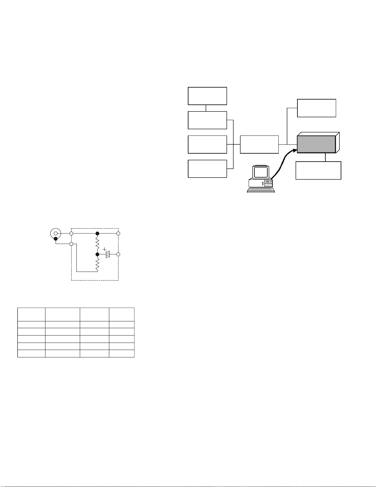
Caution:Do not connect the audio output line to
ground, and be certain that the speaker has
adequate capability to handle the audio
output from the radio.
Because of the bridge audio amplifier circuit used in the radio, it is necessary to construct and use a simple audio load test
adapter as shown in the schematic diagram
below, when conducting receiver alignment steps.
3.5 PLUG
10W
GND
2-ohm
10W
(4-ohm Dummy Load)
470uF
Alignment Channel Frequencies
Channel
CH1 37.0 MHz None None
CH2 43.5 MHz None None
CH3 50.0 MHz None None
CH4 43.5 MHz 151.4 Hz None
CH5 43.5 MHz None 023
Frequency CTCSS DCS
(simplex) Encode Encode
PLL & Transmitter
Set up the test equipment as shown for transmit-
ter alignment.
Maintain the supply voltage at 13.4 V DC for all
steps.
50-Ohm
Dummy Load
RF Signal
Generator
Inline Wattmeter
Deviation Meter
Frequency
Counter
RF Sampling
Coupler
CT-71 connection
Cable
PC
COM port
Transceiver
Power Supply
13.4V DC
PLL VCV
r Connect the positive lead of the DC voltmeter to
test point TP1010 (VCV) on the Main Unit, as in-
dicated in the figure, and connect the negative
lead to chassis ground.
r Set the transceiver to the low band edge fre-
quency channel (CH1), then adjust T1005 on the
Main Unit for 7.0 ± 0.1 V on the voltmeter.
r Key the transmitter, and adjust T1006 on the Main
Unit for 7.0 ± 0.1 V on the voltmeter.
r Next select to the low edge frequency channel
(CH1) and confirm the VCV is 1.6 ± 0.3 V on the
voltmeter.
r Key the transmitter, and confirm the VCV is 1.7 ±
0.3 V on the voltmeter.
PLL Reference Frequency
With the wattmeter, dummy load and frequency
counter connected to the antenna jack, select the
band center frequency channel (CH2) and select the
“low” power output level.
Key the transmitter, and adjust TC1001 on the
Main Unit, if necessary, so the counter frequency is
within 100 Hz of the channel center frequency for
the transceiver version.
5-2
Alignment
Transmitter Output Power
The following transmitter parameters can be adjusted from the computer by utilizing the Alignment
Software. Refer to the onboard help of the Alignment Software Manual for details.
r Select the band center frequency channel (CH2),
and select the “high” power output level.
Key the transmitter and adjust “TX PWR Hi“ for a
power output of 120 Watts (± 3.0 W) as indicated
on the wattmeter.
r Stay on the band center frequency channel (CH2),
and select the “low” power output level.
Key the transmitter and adjust “TX PWR L3“ for
a power level of 50 Watts (± 2.0 W) as indicated
on the wattmeter.
Transmitter Deviation
The following modulation parameters can be adjusted from the computer by utilizing the Alignment
Software. Refer to the onboard help of the Alignment Software Manual for details.
Microphone Audio Modulation Level
r Select the band center frequency channel (CH2),
and select the “low” power output level.
r Adjust the AF generator for 50mV (–30dBm) out-
put at 1 kHz, as applied to the microphone jack.
r Key the transmitter and adjust “MAX Dev (wide)“
for maxi-mum deviation of ±4.2 kHz ± 0.2 kHz as
indicated on the deviation meter.
TP1010T1005T1006 TC1001
5-3
Alignment
Power Supply
CTCSS Modulation Level
r Select the “low” power output level.
r Select the band center frequency channel (CH4),
with 151.4 Hz CTCSS encode, and reduce the AF
generator injection to zero.
r Key the transmitter and adjust “CTCSS Dev (wide)“
for CTCSS deviation of ±0.75 kHz (± 0.1 kHz) as
indicated on the deviation meter.
DCS Modulation Level
r Select the “low” power output level.
r Select the band center frequency channel (CH5),
with 023 DCS code, and reduce the AF generator
injection to zero.
r Key the transmitter and adjust “DCS Dev (wide)“
for DCS deviation of ±0.75 kHz (± 0.1 kHz) as indicated on the deviation meter.
Receiver
The sensitivity parameters can be adjusted from
the computer by utilizing the Alignment Software.
Refer to the onboard help of the Alignment Software
Manual for details.
r Set up the test equipment as shown for receiver
alignment, and install the audio test adapter.
50-Ohm
Dummy Load
Inline
Wattmeter
Deviation
Meter
Frequency
Counter
RF Sampling
Coupler
CT-71
Connection
Cable
AC Volt
Meter
RF Signal
Generator
13.8V DC
13.4
Transceiver
AF Generator
SINAD
Meter
AF Test
Adapter
T1002T1003T1004 T1001
5-4

r With the transceiver set to the band center fre-
quency channel (CH2), and with the RF signal
generator tuned to the same frequency, set the
generator for ±3.0 kHz deviation with 1 kHz tone
modulation, and set the output level for –6.0 dBµ
at the antenna jack.
r Adjust T1001, T1001, T1001 and T1004 the re-
ceiver front-end tuning for optimum SINAD, reducing signal generator output level as necessary
for proper meter deflection.
r After the previous step, the final signal genera-
tor level should be less than –6 dBµ for 12dB
SINAD.
r With the transceiver set to the band high fre-
quency channel (CH3), and with the RF signal
generator tuned to the same frequency, set the
generator for ±3.0 kHz deviation with 1 kHz tone
modulation, and set the output level for –6.0 dBµ
at the antenna jack.
r After the previous step, and confirm the final sig-
nal generator level should be less than –6 dBµ
for 12dB SINAD.
r With the transceiver set to the band low frequency
channel (CH1), and with the RF signal generator
tuned to the same frequency, set the generator
for ±3.0 kHz deviation with 1 kHz tone modulation, and set the output level for –5.0 dBµ at the
antenna jack.
r After the previous step, and confirm the final sig-
nal generator level should be less than –5 dBµ
for 12dB SINAD.
Squelch Threshold
The squelch parameters can also be adjusted from
the computer by utilizing the Alignment Software.
Refer to the onboard help of the Alignment Software
Manual for details.
Tight SQL RSSI LEVEL
r Select the band center frequency channel (CH2),
and with the RF signal generator turned to the
same frequency, set the generator for ±3.0 kHz
deviation with 1 kHz tone modulation, and set
the output level for 12.0 dBµ at the antenna jack.
Threshold NSQ LEVEL
r Select the band center frequency channel (CH2),
and with the RF signal generator turned to the
same frequency, set the generator for ±3.0 kHz
deviation with 1 kHz tone modulation, and set
the output level for –6.0 dBµ at the antenna jack.
Tight SQL NSQ LEVEL
r Select the band center frequency channel (CH2),
and with the RF signal generator turned to the
same frequency, set the generator for ±3.0 kHz
deviation with 1 kHz tone modulation, and set
the output level for 6.0 dBµ at the antenna jack.
5-5
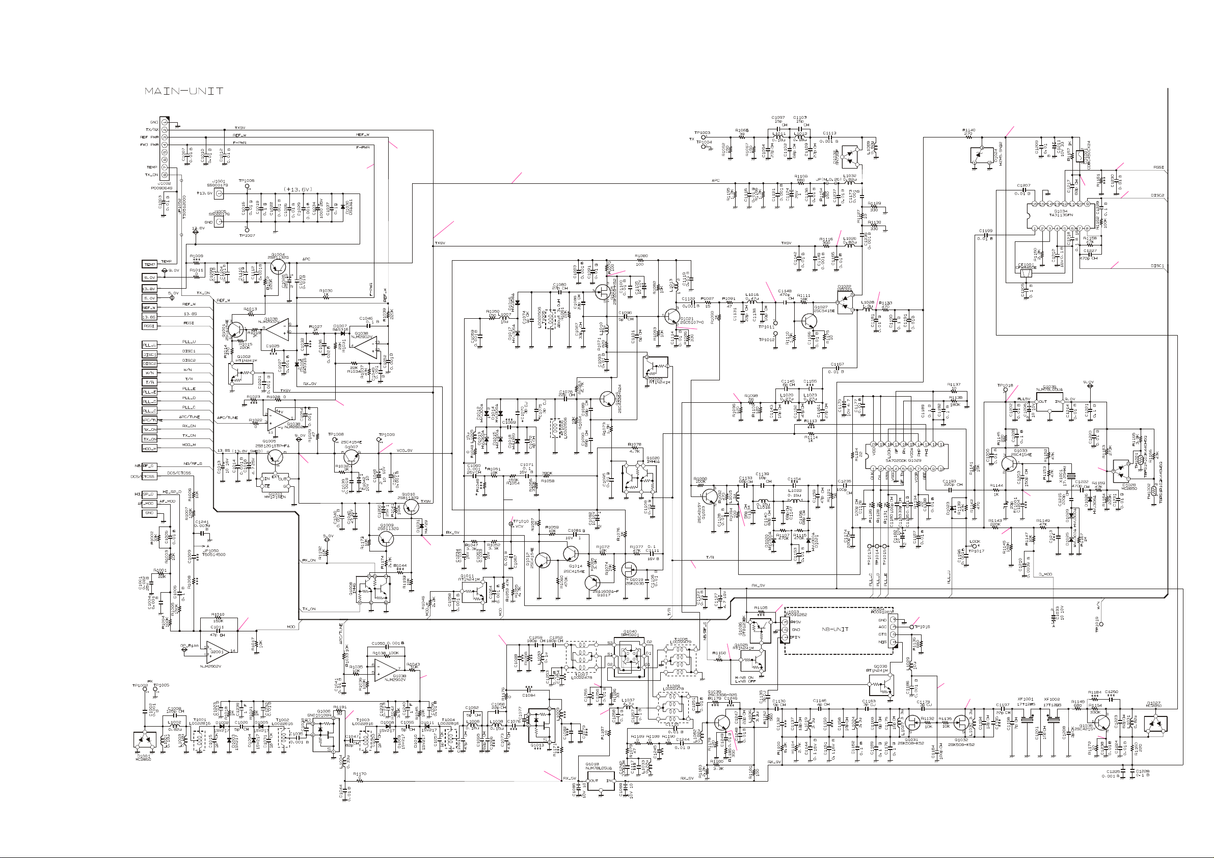
Circuit Diagram
MAIN Unit
MAIN Unit
2.3V
2.75V
(2.45V)
0.4V
0V (8.8V)
5 ~ 7V
7.7V (7.9V)
-2 dBm
2.5V
(2.5V)
+8 dBm (+12 dBm)
(0 dBm)
3.4V
(1.6V)
0V (5.6V)
5V (5V)
(5.6V)
(2.06V)
(1.0V)
(0.64V)
-119 dBm
2.0V (2.0V)
8.9V
(8.9V)
0V (3.5V)
8V (8V)
0V
(8.8V)
3.5V (4.95V)
-116 dBm
4.0V (3.7V)
0V (0.9V)
0V (4.7V)
0V (5V)
NB on:(5V)
NB off:(0V)
4.5V
(4.5V)
(3.9V)
(1.7V)
2V (2V)
LOCK:4.9V
0V (8.7V)
0V (4.3V)
(0V)
(2.2V)
(0.03V)
0V (5V)
(2V)
XX : TX 43.5 MHz, MIC Input Level 1 kHz 3.0mVrms (STD Dev), High Power
(XX) : RX 43.5 MHz, RF Input Level 40dbµ emf (MOD=1.0 kHz, Dev=3.0 kHz), EXT SP OUT 10% Distn 14.0W
[XX] : Noise Blanker ON
6A-1
 Loading...