

Vertex Standard VX-510 Operating Manual

VX-510
VHF/UHF Hand-Held Portable
Land Mobile Transceiver
OPERATING MANUAL
MANUAL DE OPERACIÓN
Vertex Standard LMR, Inc.
4-8-8 Nakameguro, Meguro-Ku, Tokyo 153-8644, Japan


English
VX-510 OPERATING MANUAL
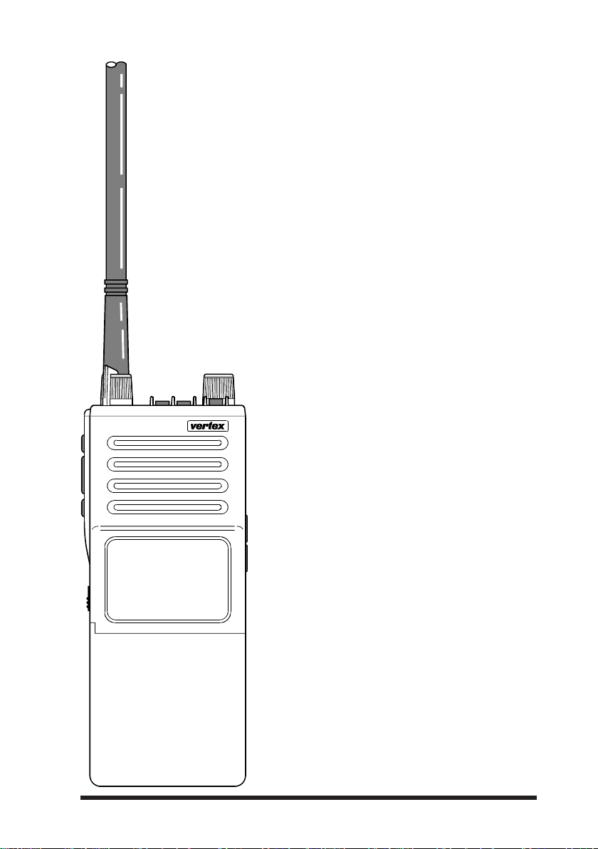
VX-510 Series
VHF/UHF Hand-Held Portable
Land Mobile Transceiver
The VX-510 is a frequency-synthesized, microprocessor-controlled FM hand-held portable transceiver providing up to five watts
of power output on up to 32 channels in the
VHF or UHF Land Mobile Bands. Designed
specifically for commercial and professional
applications, the VX-510 is housed in highstrength die-cast aluminum alloy, sealed to
MIL-810 C, D & E intrinsically safe (I/S)
and weather-tight specifications*.
User selectable features include a four-mode
display with channel name or number, upright or inverted for easy viewing when on
your belt; selective channel scanning, adjustable-pause priority scanning, and variable transmitter power output.
Other user-selectable features include pushbutton display illumination, 2-tone decoder
enable/disable (with optional F2D-5 Unit
installed), and manual squelch override. The
VX-510 is easily programmed by your
dealer using a Yaesu Service Kit with an
IBM PC-compatible computer.
Please read this manual carefully to become
familiar with the features of the VX-510.
*approval pending
1

VX-510 OPERATING MANUAL
SPECIFICATIONS
General VHF (Low Band) VHF (High Band) UHF
Frequency range (MHz): 29.8 – 38 MHz (vers.A) 146 – 174 MHz 450 – 488 MHz
Channels: Up to 32 Up to 32 Up to 32
Maximum Channel Spread: 8.3 MHz (vers. A) 28 MHz 20 MHz
Minimum Channel Spacing: 20 kHz
Programming Channel Step: 5/6.25 kHz 5/6.25 kHz 10/12.5 kHz
Emission Type: 16K0F3E
Supply Voltage : 7.2 V DC 10% 7.2 V DC 10% 7.2 V DC 10%
Current Consumption: 50 mA (stby, saver off) 50 mA (stby, saver off) 50 mA (stby, saver off)
Case Size (WxHxD): 59x149x39mm 59x149x39mm 59x149x39mm
Weight (approx.): 570 grams 570 grams 570 grams
Receiver
Receiver Circuit Type: Double-conversion Double-conversion Double-conversion
Intermediate Frequencies: 21.6 MHz (ver. A) 21.6 MHz & 455 kHz 47.9 MHz & 455 kHz
12-dB SINAD Sensitivity: better than 0.20μV better than 0.25μV better than 0.25μV
20-dB Noise Quieting: better than 0.30μV better than 0.35μV better than 0.35μV
Squelch Threshould: better than 0.18μV better than 0.20μV better than 0.20μV
Adjacent Channel Selectivity: 75 dB 65/75 dB 65/75 dB
Image Rejection: 80 dB 75 dB 75 dB
Intermodulation Response: 70 dB 72 dB 72 dB
Hum & Noise: 50 dB 44/50 dB 40/45 dB
Audio Response:
AF output (for 5% THD): 0.5 watts @16 0.5 watts @16 0.5 watts @16
38 – 50 MHz (vers.B)
(simplex or semi-duplex) (simplex or semi-duplex) (simplex or semi-duplex)
12 MHz (vers. B)
(12.5 kHz optional)
(11K0F3E optional)
19 mA (stby, saver on) 19 mA (stby, saver on) 19 mA (stby, saver on)
200 mA (receive) 200 mA (receive) 200 mA (receive)
2000 mA (transmit) 2000 mA (transmit) 2000 mA (transmit)
Superheterodyne Superheterodyne Superheterodyne
16.9 MHz (vers.B)
& 455 kHz
+3/–8 dB from the 6 dB/oct. +3/–8 dB from the 6 dB/oct. +3/–8 dB from the 6 dB/oct.
De-emphasis curve De-emphasis curve De-emphasis curve
15/30 kHz 12.5/25 kHz
11K0F3E/16K0F3E 11K0F3E/16K0F3E
Transmitter
Power Output: 5W/1W 5W/1W 5W/1W
Frequency Stability: ±10 ppm ±2.5 ppm ±2.5 ppm
Modulation System: variable reactance variable reactance variable reactance
Maximum Deviation: ±5 kHz
Audio Response: TIA/EIA-603 3.2.6 TIA/EIA-603 3.2.6 TIA/EIA-603 3.2.6
FM Hum and Noise: better than
Spurious Emissions: 60 dB below carrier 60 dB below carrier 60 dB below carrier
AF Distortion (@ 1 kHz): < 5% @60 % modulation < 5% @60 % modulation < 5% @60 % modulation
Microphone Type: 2-k condenser 2-k condenser 2-k condenser
(±2.5 kHz optional)
–
50 dB better than –45/50 dB better than –45/50 dB
Specifications may be subject to change without notice or obligation.
±2.5/±5 kHz ±2.5/±5 kHz
2

VX-510 OPERATING MANUAL
ACCESSORIES & OPTIONS
MH- 30
FNB-29A 7.2 V/1700 mAh Ni-Cd Battery Pack
CD-8 Desktop Battery Rapid-Charger (used w/PA-14B/C)
PA-14B 120 V AC Mains Adapter
PA-14C 230 – 240 V AC Mains Adapter
CS-500 Overnight Desktop Charger
ATL-1A VHF Low Band Helical Flex Antenna (30 – 36 MHz)
ATL-1B VHF Low Band Helical Flex Antenna (36 – 42 MHz)
ATL-1C VHF Low Band Helical Flex Antenna (42 – 50 MHz)
A TV-3B VHF Helical Flex Antenna (148 – 155 MHz)
A TV-3C VHF Helical Flex Antenna (150 – 162 MHz)
A TV-3D VHF Helical Flex Antenna (155 – 164 MHz)
A TV-3E VHF Helical Flex Antenna (162 – 174 MHz)
ATU-5D UHF Helical Flex Antenna (450 – 470 MHz)
ATU-5F UHF Helical Flex Antenna (470 – 512 MHz)
FVP-22 Encryption Unit
F2D-5A/B Two-Tone Sequential Decoder
FTT-7 DTMF Keypad Tone Generator (16 keys)
FTT-7D DTMF Keypad Tone Generator w/Decoder
FTE-19 ANI (Auto Numbering Identification) Unit
CE-21 Programming Software
VPL-1 Programming Cable
VTP-20 VX-Trunk II VX-Trunking Portable Logic Board
CLIP-4 Belt Clip
SBC-1 Swivel Belt Adaptor (Requires LCS-2)
A2B
Speaker/Microphone
3
VX-510 OPERATING MANUAL
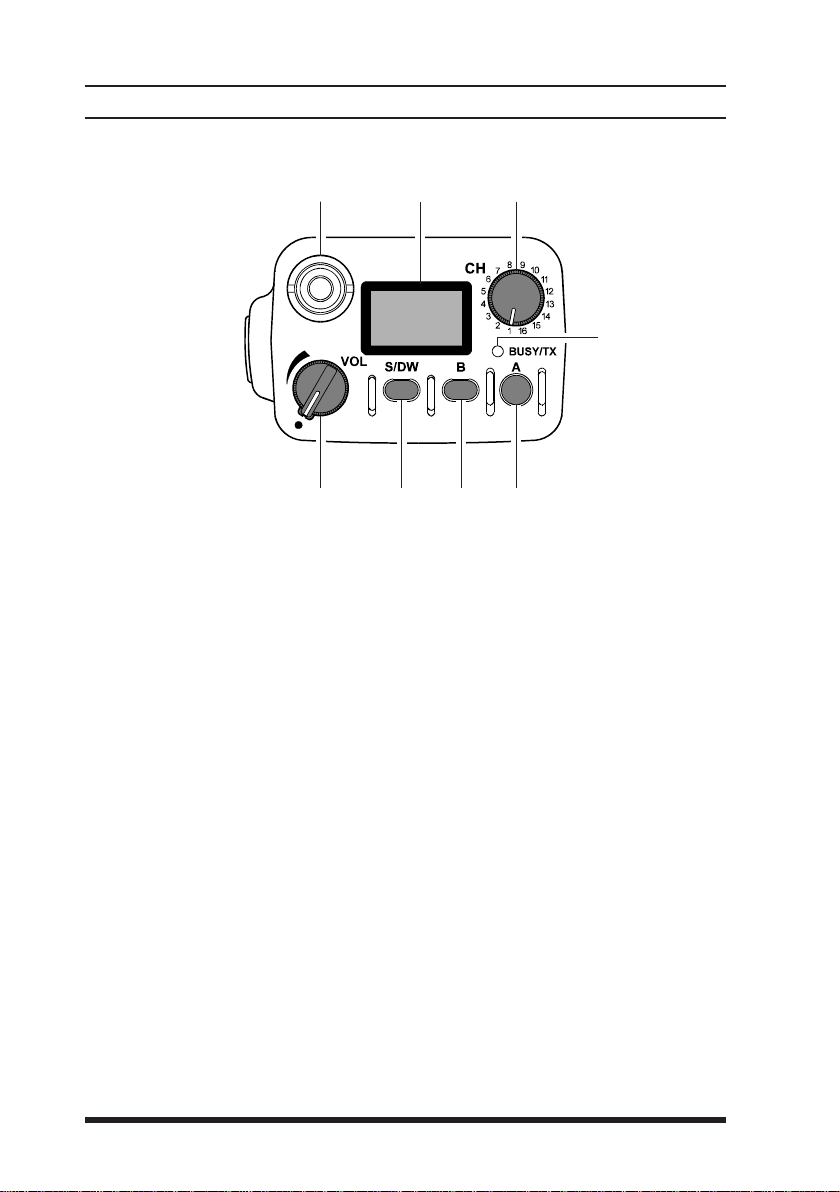
CONTROLS & CONNECTORS
Top panel
⑥⑦⑧
⑤
① ②
(1)
VOL Control
This control adjusts the volume of the receiver, and turns the radio off
when rotated fully counterclockwise to the click-stop
(2)
S/DW Button (Scan/Dual Watch)
Momentarily (< 1sec.) pressing this button turns the channel scanner on
and off. Pressing and holding (> 1 sec.) this button activates the Dual Watch
feature (explained later).
(3)
B Button
Pressing and holding this button more than 2 seconds (but less than 4
seconds) activates functions as programmed by your dealer and determined
by your system requirements (See “P
13). Pressing and holding this button more than 4 seconds inverts the
LCD display to either frontward or backward facing readout (the backward display is convenient for viewing when wearing the transceiver on
your belt).
③④
RE-PROGRAMMED FUNCTIONS”, page
4
VX-510 OPERATING MANUAL
CONTROLS & CONNECTORS
(4)
A Button
Pressing and holding this button more than 2 seconds (but less than 4
seconds) also activates an assigned function (programmed by your dealer).
Pressing and holding this button more than 4 seconds causes the selected
channel to be assigned as the Priority Channel for use with Priority Scanning and Dual Watch functions (explained later).
(5)
BUSY/TX Indicator
This lamp blinks green when a signal is being received (or the squelch is
opened by pressing the MON RES button) and red when transmitting. To
avoid interference, do not transmit if the lamp is glowing green. When the
battery almost depleted, this lamp blinks red, indicating that the battery
needs recharging or replacement very soon.
(6)
CH Rotary Selector
This rotary switch selects the operating channel. If a channel is selected
------
that is not available for operation, “
rapid warning beeper (2 beeps/sec.).
--
---
-” is displayed, accompanied by a
------
--
(7)
Antenna Jack
This threaded-type jack accepts the supplied flexible antenna. Any other
antenna types used here must be designed for the programmed operating
frequencies.
(8)
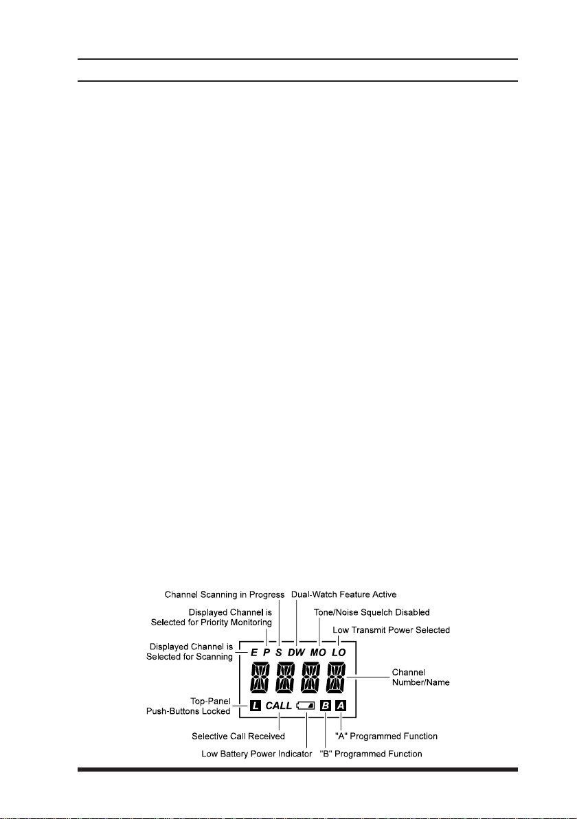
Liquid Crystal Display
In addition the channel number name, the display includes some operating
status symbols, indicated in the diagram below.
5
VX-510 OPERATING MANUAL
CONTROLS & CONNECTORS
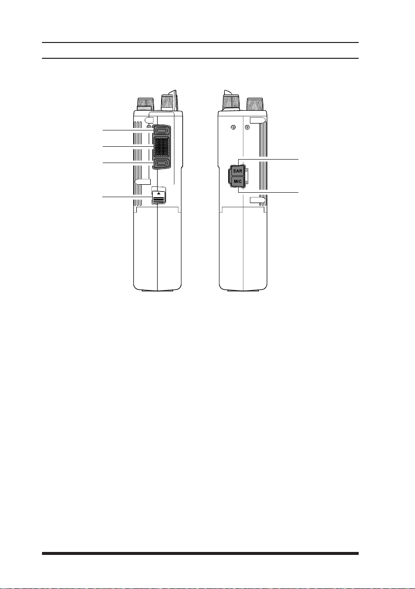
Side Panel Buttons
①
②
③
⑤
④
(1)
MON RES (Monitor/Reset) Button
Pressing and holding this button more than 2 seconds (but less than 4
seconds) disables the tone squelch, and permits monitoring of stations transmitting on the selected channel while still keeping your receiver quiet from
noise (“MO” will appear at the top right of the LCD). Press it again to only
hear calls within your network.
Pressing and holding this button more than 4 seconds toggles the tone and
noise squelch override, allowing all stations (and noise) on the channel to
be heard. This may be used to hear weak stations whose signals would not
normally open the squelch. Do this to pre-adjust the VOLume control before receiving calls.
(With Selective Calling Option)
When the two-tone sequential decoder unit (F2D-5) is installed, and a se-
lective call has been received (“CALL ” indicator on), pressing and hold-
ing this button more than 2 seconds (but less than 4 seconds) will reset the
call function on the current channel and silence the receiver, otherwise
pressing and holding this button more than 4 seconds resets the call function on ALL channels.
⑥
6

VX-510 OPERATING MANUAL
CONTROLS & CONNECTORS
(2)
PTT (Push-To-Talk) button
Hold this button to transmit (the “BUSY/TX” indicator glows red).
(3)
LAMP/LOCK button
Press this button momentarily (<1 sec.) to illuminate the display for five
seconds. Pressing and holding (>1 sec.) this button locks top-panel push-
buttons (S/DW, B, A, and the optional DTMF keypad); this can be en-
abled to prevent radio settings from being disturbed.
(4)
Battery Release button
Slide this button in the direction of the arrow (upward) for battery removal.
(5)
EAR Jack
This provides audio output for an earphone or the optional MH-30
External Speaker/Microphone here. The internal speaker is disabled when
a plug is inserted into this jack.
(6)
MIC Jack
Connect the optional MH-30
microphone is disabled when this jack is used.
Speaker/Microphone here, the internal
A2B
A2B
7
VX-510 OPERATING MANUAL
OPERATION
Preliminaries
If the transceiver has not been used since leaving the factory, fully charge
the battery using CD-8 unit (with P A-14B or C) before using it.
Mount the battery on the transceiver as described and shown in the photo
below. Also, install the antenna on the jack on top of the transceiver by
screwing the connector into the jack until it is finger-tight.
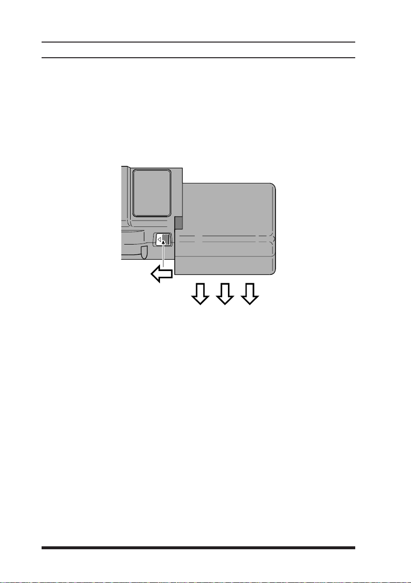
Battery Removal & Replacement
Make sure that the VOL control is set into the off click-stop, and
remove the protective soft or hard case, if used.
Grasp the transceiver with your left hand, so your palm is over the
speaker and your thumb is on the Battery Release Button.
Move the button in the direction indicated by the arrowhead, while
using your right hand to slide the battery pack toward the side with
the button. The battery pack should slide smoothly out of its track.
To replace the Ni-Cd pack, repeat the second and third steps above,
simply sliding the battery case in the other direction after aligning
the shorter side of the battery pack with the track below the Battery
Release Button.
8

VX-510 OPERATING MANUAL
OPERATION
Preliminary Steps
Before operating the transceiver for the first time:
Charge the battery pack and connect the supplied helical rubber flex
antenna to the antenna jack on the top of the transceiver. Never op-
erate the transceiver without an antenna connected.
If you have a Speaker/Mic, we suggest you do not connect it until
you are familiar with basic operation.
Before proceeding, please review the “Top & Side Panel Controls”
outline, if you have not already, to familiarize yourself with the
functions of the controls.
Basic Operation
Switch on the transceiver by rotating the VOL control clockwise
out of the click-stop (a momentary beep will sound). For now, adjust the control to about mid-position (12-o’clock), later you can
adjust the level to suit the operating environment.
Rotate the CH knob to select a channel for operation, the LCD will
------
show the currently selected channel. If “
with a rapid (2 beeps/sec.) beeping tone, the selected channel position is not available for operation.
To transmit, wait until the channel is clear (“BUSY/TX” LED off),
then press in the PTT switch on the side of the transceiver while
speaking across the face of the radio. A clear normal voice will provide the best quality transmission. For maximum battery life, select
low power output (covered later) whenever possible. During trans-
mission the “BUSY/TX” indicator glows red. Release the PTT
switch to receive.
To receive weak stations better, try positioning the radio as high and
far away from your body as possible, or disable the squelch mo-
mentarily by holding the MON RES button on the side of the radio
for > 4 sec. (until the second low/high beep sounds). With the squelch
disabled, the “BUSY/TX” indicator will blinks green and channel
noise and weak stations can be heard. To quiet the radio again, press
the MON RES button again momentarily.
When you are done operating, be certain to turn the VOL control to
the off position to conserve battery life.
--
---
-” is displayed, along
------
--
9

VX-510 OPERATING MANUAL
OPERATION
An important note about your radio !
Some of the radio/button functions discussed next will only operate in
your radio if so programmed by your dealer, or after the installation of
certain internal optional units. In this way, the radio’s operation can be
simplified and customized specifically for the user according to network requirements. If pressing a button on your radio does not result
in the same function described in this manual, or if you are uncertain
of the functions your particular radio is configured with, contact your
dealer. See “P
Scanning
Scanning allows you to sequentially check for calls on all or only those
channels you select. To start scanning, press the S/DW button momen-
tarily. A beep then sounds and the display will clear and show “
Scanning will pause when a signal is received, at which time the channel
number (or alphanumeric tag) will be displayed. A small “S” will be dis-
played above the channel, indicating the scanner is still active, but paused.
RE-PROGRAMMED FUNCTIONS” on page 13.
SCASCA
SCA
SCASCA
NN
N
NN
”.
During this pause, you can press the PTT switch and talk to the station.
Otherwise, scanning will resume a few seconds after the signal is no longer
present. While scanning, if you momentarily press the PTT switch, opera-
tion automatically shifts to a default channel. This default channel can be
set to the priority channel (both “P” and “S/DW” are displayed), lastbusy channel, or home channel, depending on how your radio was pro-
grammed.
To stop scanning, simply press S/DW momentarily again. Operation will
return to the channel that was last selected when scanning was activated.
If enabled by dealer programming, you may select only the channels you
want to scan, and have others skipped-over by performing the following
routine.
Turn the radio OFF, then depress the S/DW button while turning the radio
PROPRO
GG
PRO
G
back ON again. “
” will momentarily appear on the display, after
PROPRO
GG
which it will revert to the currently selected channel (this indicates you are
ININ
HH
IN
H
in the programming mode). If user-access is disabled “
” will appear
ININ
HH
briefly.
10

VX-510 OPERATING MANUAL
OPERATION
Use the CH knob to select a channel, then press the S/DW button to enable the channel for scanning (“E” will appear in the upper left corner of
the LCD). Repeat this process for each channel you want the scanner to
check.
To remove a channel from those to be scanned, press S/DW again, so that
“E” no longer appears in the display.
After you have enabled all the channels you want to scan, turn the radio
off, then on again to return to normal operation.
Priority Scanning
Priority scanning allows you to scan and monitor channels while the receiver periodically checks for calls on a pre-selected (“priority”) channel.
You may want to use this feature if you want to scan different channels,
but don’t want to miss a call for you on a primary dispatch, emergency or
tactical frequency. After a call has been received on the priority channel,
operation returns to the programmed default channel scheme, as mentioned
before. Only one channel at a time can be selected as the priority channel.
To set the currently displayed channel as the priority channel, just
press and hold the A button for 4 sec. A small “P” will now appear
at the top left corner of the display whenever this channel is selected, along with an accompanying “beep”.
When a priority channel has been selected, the scanner will check the priority channel regularly as you scan the other channels. If a signal appears
on the priority channel, the scanner will pause and operation will jump to
the priority channel. Otherwise, the scanner will pause on active non-priority signals as previously described.
If a call comes in on a non-priority channel that you need to respond to,
just press the PTT switch while the scanner is paused on that channel. As
long as no call comes in on the priority channel, you can send and receive
on the other channel: scanning will resume when you finish and the channel clears.
11

VX-510 OPERATING MANUAL
OPERATION
Dual Watch
If you need to operate on a non-priority channel while still checking for
calls on the priority channel, the Dual Watch feature let’s you to do this
without using the scanner. When enabled, operation on any selected nonpriority remains normal as before, however, when a signal is received on
the priority channel or when you press the PTT switch, operation immedi-
ately shifts to the priority channel. The rate at which the Dual Watch feature samples the priority channel can be set by the user.
To begin Dual Watch operation, first assign a priority channel as
described before, then select the non-priority channel you wish to
operate on.
Press and hold the S/DW button until the second beep sounds, “DW”
(but not “S”) will appear at the top of the display.
To manually shift to the priority channel, press the PTT switch. At
this time you make transmit, otherwise, if no signal is received within
2 seconds, operation will revert back to the other selected Dual Watch
channel.
To turn off the Dual Watch Feature, press and hold the S/DW button
again (“DW” will disappear in the display).
12
Low Battery Power Indication
When the rechargeable Ni-Cd battery pack voltage reaches a low level,
the “
the “BUSY/TX” indicator will blinks red. Immediately remove the Ni-
Cd pack and install a freshly char ged battery pack, or insert the radio
into the charging stand for a complete recharge cycle. If you plan to
operate your radio for extended periods of time, you may want to keep
a spare, fully-charged pack handy.
” indicator appears at the lower right corner of the LCD, and
 Loading...