

Vertex Standard VX-4500, VX-4600 Operating Manual
VX-4500
VX-4600
OPERATING MANUAL
VX-4600VX-4500
PROGRAMMABLE FUNCTIONS/FEATURES
Six Programmable Function Keys
5-tone Encode/Decode
ARTS (Auto Range Transpond System
Dimmer/Lamp
Horn Alert
Public Address
Lock
Beep OFF
Encryption
Scan
Group Scan
Dual Watch
FM-Scan (Follow-Me Scan
TA Scan
VOX
(
: VX-4600 ONLY
2-tone Encode/Decode
MDC-1200
)
REC & PLAY (Requires DVS-8
Clear Voice
AF Min Volume
Talk Around
Emergency
Lone Worker
Direct Channel Entry
Code Up/Down
Code Set
Speed Dial
)
DTMF Code Set
ID Check
TX Save Disable
®
Encode/Decode
)
)
Congratulations!
You now have at your fingertips a valuable communications tool: a Vertex Standard
two-way radio! Rugged, reliable and easy to use, your Vertex Standard radio will keep
you in constant touch with your colleagues for years to come, with negligible maintenance downtime.
Please take a few minutes to read this manual carefully. The information presented
here will allow you to derive maximum performance from your radio.
We’re glad you joined the Vertex Standard team. Call on us anytime, because communications is our business. Let us help you get your message across.
NOTICE !
There are no owner-serviceable parts inside the transceiver. All service jobs
must be referred to an authorized Vertex Standard Service Representative.
Consult your Authorized Vertex Standard dealer for installation of optional
accessories.
SAFETY/WARNING INFORMATION
WARNING - DO NOT operate the VX-4500/-4600 radio when any person(s)
(bystanders) outside the vehicle are within the distances shown in the chart at
the bottom of this section.
Safety Training information:
Antennas used for this transmitter must not exceed an antenna gain of 0 dBi.
The radio must be used in vehicle-mount configurations with a maximum
operating duty cycle not exceeding 50 %, in typical Push-to-Talk configurations.
This radio is restricted to occupational use, work related operations only
where the radio operator must have the knowledge to control the exposure
limits of passengers and bystanders by maintaining the minimum separation
distance shown below.
Failure to observe these restrictions will result in exceeding the FCC RF exposure limits.
Antenna Installation:
For rear deck trunk installation, the antenna must be located at least the following distance away from rear-seat passengers in order to comply with the
FCC RF exposure requirements.
For roof top installations, the antenna must be placed in the center of the roof.
Unsafe Radiation Distance
VHF Model
4.6 Feet (1.4 m
)
UHF Model
3.9 Feet (1.2 m
)
INTRODUCTION
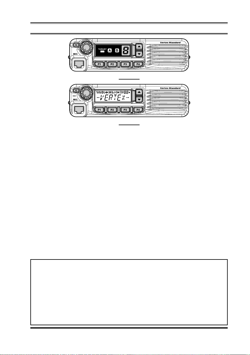
VX-4500
VX-4600
The VX-4500/-4600 Series are full-featured FM transceivers designed for flexible
mobile and base station business communications in the VHF or UHF Land Mobile
bands. These transceivers are designed for reliable business communications in a
wide variety of applications with a wide range of operating capability provided by
their leading-edge design.
The VX-4500 allows up to 8 memory channels. The VX-4600 allows up to 512
memory channels which can each be programmed with an 8-character Alpha-Numeric Tag.
Important channel frequency data is stored in EEPROM and flash memory on the
CPU, and is easily programmable by Vertex Standard dealers using a personal computer and the Vertex Standard Programming Cable and CE115 Software.
The pages which follow will detail the many advanced features provided in the VX-
4500/-4600 Series transceiver. After reading this manual, you may wish to consult
with your Network Administrator regarding precise details of the configuration of
this equipment for use in your application.
For North American Users Regarding 406 MHz Guard Band
The U.S. Coast Guard and National Oceanographic and Atmospheric Administration have requested the cooperation of the U.S. Federal Communications Commission in preserving the integrity of the protected frequency range
406.0 to 406.1 MHz, which is reserved for use by distress beacons. Do not
attempt to program this apparatus, under any circumstances, for operation in
the frequency range 406.0 - 406.1 MHz if the apparatus is to be used in or
near North America.
VX-4500/-4600 SERIES OPERATING MANUAL 1
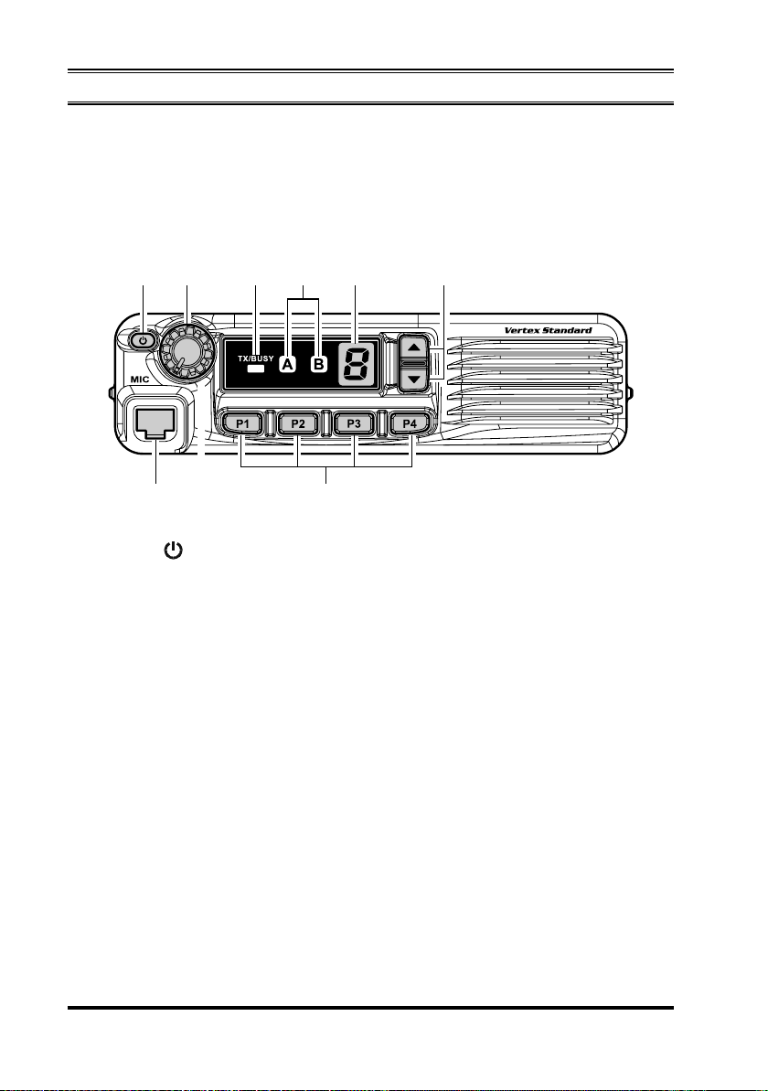
CONTROLS & CONNECTORS (VX-4500
)
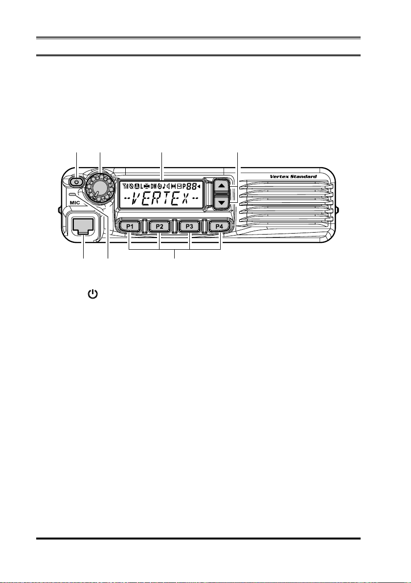
Front Panel
Important! - All buttons located on the Front Panel are Programmable Function
(PF) keys, configured according to your network requirements and programmed by
your Vertex Standard dealer. The instructions below describe a typically-configured
radio.
PWR
Press and hold in this button for 2 seconds to toggle the transceiver’s power
“on” and “off”.
VOL Knob
Turn this control clockwise to increase the volume.
Microphone Jack
Connect the microphone plug to this jack.
[P1] - [P4]
These keys can be set up for special applications, such as High/Low power
selection, Monitor, Talk-Around, etc., as determined by your network requirements and programmed by your Vertex Standard dealer.
( )
Button
Keys (Programmable Function Keys)
[]/[]
In the factory default, pressing either key changes the current channel.
Channel Number Indicator
Indicates the operating channel.
Keys (Programmable Function Keys)
VX-4500/-4600 SERIES OPERATING MANUAL2
CONTROLS & CONNECTORS (VX-4500
Transceiver Status Indicator
)
The “A” and “B” indicators show current transceiver status, which can be customized via programming by your Vertex Standard dealer to meet your communications/network requirements. The possible “A” and “B” displays are explained
below.
TX/BUSY Indicator
Indicates transceiver’s Transmit/Receive Status.
TRANSCEIVER STATUS INDICATOR
STATUS
MONI
SCAN CH
PRI-1
Low Power
TA (Talk Around
Encryption
Emergency
Horn Alert
PA
(
Public Address
Lock
ACC2
RFC
REC/PLAY
(
Required optional Unit
INDICATOR
A B
This indicator is illuminated constantly when the signaling feature is disabled. The indicator blinks while
the audio is passing normally.
Illuminates the indicator when the scan enabled
channel is recalled.
Illuminates the indicator when the Priority-1 channel is activated.
Illuminates the indicator when the radio’s transmitter is set to the “Low Power” mode.
)
)
)
Illuminates the indicator when the “Talk Around” function is activated.
Illuminates the indicator when the “Voice Scrambler”
function is enabled.
Illuminates the indicator when the “Emergency” feature is activated.
Illuminates the indicator when the “Horn Alert” feature is activated.
Illuminates the indicator when the radio is turned to
a PA amplifier.
Illuminates the indicator when the “Lock” feature is
activated.
Illuminates the indicator when the output port “2” on
the Accessory Connector is turned to “ON”.
Illuminates the indicator when the radio is in the
“Ready for Communication” condition while operating with the 2-Tone or 5-Tone signaling.
Illuminates the indicator when the incoming message is recorded or storage message is played back.
DESCRIPTION
VX-4500/-4600 SERIES OPERATING MANUAL 3
CONTROLS & CONNECTORS (VX-4600
)
Front Panel
Important! - All buttons located on the Front Panel are Programmable Function
(PF) keys, configured according to your network requirements and programmed by
your Vertex Standard dealer. The instructions below describe a typically-configured
radio.
PWR
Press and hold in this button for 2 seconds to toggle the transceiver’s power
“on” and “off”.
VOL Knob
Turn this control clockwise to increase the volume.
Microphone Jack
Connect the microphone plug to this jack.
[P1] - [P4]
These keys can be set up for special applications, such as High/Low power
selection, Monitor, Talk-Around, etc., as determined by your network requirements and programmed by your Vertex Standard dealer.
( )
Button
Keys (Programmable Function Keys)
[]/[]
In the factory default, pressing either key changes the current channel (and displayed channel number or name). Holding in either key for more than 1.5 second causes the radio to begin stepping (repeatedly) upward or downward through
the channels.
Keys (Programmable Function Keys)
VX-4500/-4600 SERIES OPERATING MANUAL4
CONTROLS & CONNECTORS (VX-4600
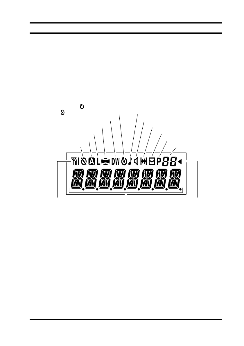
LCD (Liquid Crystal Display)
The display includes a 8-character alpha-numeric section showing Channel name
tags/identity information and error messages, and an upper icon row displaying
feature status (see below).
TX/BUSY Indicator
Indicates transceiver’s Transmit/Receive Status.
)
: “Scan” is enabled
: “Priority Scan” is activated
“Dual Watch” is activated
“Audio Compander” is activated
Low Transmit Power Mode “ON”
“AUX A” Port is activated
“Encryption” is enabled Group Number
RSSI Indicator (four steps)
8 Character Alpha-numeric Display
“Call” indicator
Receiver Monitor
“Talk-Around” is enabled
“Voice Message” is received
Priority-2 Channel
“Group Scan” is enabled
VX-4500/-4600 SERIES OPERATING MANUAL 5
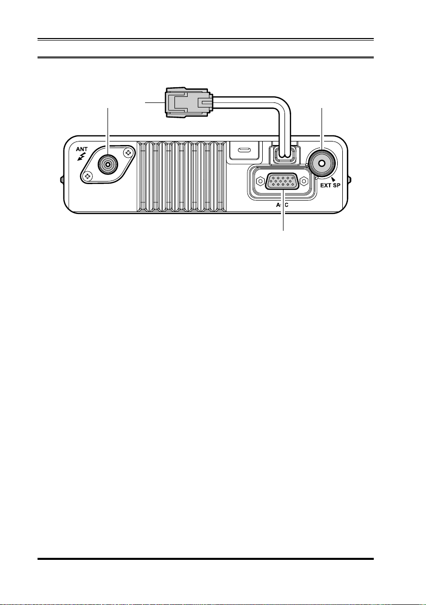
CONTROLS & CONNECTORS
Rear Panel
Antenna Jack
The 50-Ohm coaxial feedline to the antenna must be connected here, using a
mini-UHF plug.
13.6V DC Cable Pigtail with Connector
The supplied DC power cable must be connected to this 2-pin connector. Use
only the supplied fused cable, extended if necessary, for power connection.
External Speaker Jack
An external loudspeaker may be connected to this 2-contact, 3.5-mm mini-phone
jack.
Caution: Do not connect either wire of this line to ground, and be certain that
the speaker has adequate capability to handle the audio output (12 W) from the
radio.
D-Sub 15-Pin Accessory Connector
External TX audio line input, PTT (Push To Talk), Squelch, and external RX
audio line output signals may be obtained from this connector for use with accessories such as data transmission/reception modems, and external Channel
control input etc.
VX-4500/-4600 SERIES OPERATING MANUAL6

BASIC OPERATION OF THE TRANSCEIVER
Important! - Before turning on the radio the first time, confirm that the power connections have been made correctly and that a proper antenna is connected to the
antenna jack.
Switching Power ON/OFF
Press and hold in the PWR
display will become illuminated.
Press the []/[] key to choose the desired operating channel. A channel name
will appear on the display.
In the VX-4600, if you want to select an operating channel from a different
group, press the PF (Programmable Function) key which is programmed to the
Group Up/Down feature to select the group you want before selecting the operating channel. See page 8 for more information on the Programmable Function
keys.
Setting the Volume
Turn the VOL knob clockwise to increase the volume, and counterclockwise to
decrease it.
Transmitting
To transmit, monitor the channel and make sure it is clear.
THIS IS AN FCC REQUIREMENT!
Press the PF key which is programmed to the Monitor feature to listen for chan-
nel activity.
When receiving a call, transmit only after the incoming call ends. The radio
cannot receive a call and transmit simultaneously.
Press the PTT switch.
If the channel is clear, the TX/BUSY indicator will glow red. The radio is now
transmitting. While holding in the PTT switch, speak across the face of the microphone in a clear and normal voice. For best transmission, hold the microphone
about 1-1/2 to 2 inches away from your mouth. Release the PTT switch to receive.
If the Busy Channel Lockout feature has been programmed on a channel, the
radio will not transmit when a carrier is present. Instead, the radio will generate
a short beep three times and the VX-4600 indicates “CH BUSY” on the display.
Release the PTT switch and wait for the channel to be clear of activity.
If CTCSS or Digital Coded Squelch (DCS) Lockout has been programmed on a
channel, the radio can transmit only when there is no carrier being received or
when the carrier being received includes the correct CTCSS tone or DCS code.
( )
button for 2 seconds to turn the radio on. The
VX-4500/-4600 SERIES OPERATING MANUAL 7

BASIC OPERATION OF THE TRANSCEIVER
Transmit Time-Out Timer
If the selected channel has been programmed for automatic time-out, you must limit
the length of each transmission. While transmitting, a beep will sound 10 seconds
before time-out. Another beep will sound just before the deadline; the red “TX”
indicator will disappear and transmission will cease soon thereafter. On the VX-
4600, “TIME OUT” will be indicated on the display. To resume transmitting, you
must release the PTT switch and wait for the “penalty timer” to expire (if you press
the PTT switch before this timer expires, the timer restarts, and you will have to wait
another “penalty” period)
Key Lock
In order to prevent accidental operating function/feature change or inadvertent transmission, various aspects of the front panel’s keys may be locked out.
To activate the Locking feature, press and hold in the [P1] key while turning the
radio on. To disable the Locking feature, repeat this power-on procedure.
ADVANCED OPERATION
Programmable Function (PF) Keys
The VX-4500/-4600 includes six Programmable Function (PF) keys. The PF button functions can be customized, via programming by your Vertex Standard dealer,
to meet your communications/network requirements. Some features may require the
purchase and installation of optional internal accessories. The possible PF key programming features are illustrated below, and these functions are explained on the
pages to follow. For further details, contact your Vertex Standard dealer. For future
reference, check the box next to the function that has been assigned to each PF key
on your particular radio, and keep it handy.
VX-4500/-4600 SERIES OPERATING MANUAL8
 Loading...