

Vertex Standard VX-4200E Series, VX-4204E, VX-4207E Operating Manual
VX-4200E
OPERATING MANUAL
SERIES
P1
P2
P4
P3
A
VERTEX STANDARD CO., LTD.
4-8-8 Nakameguro, Meguro-Ku, Tokyo 153-8644, Japan
VERTEX STANDARD
US Headquarters
10900 Walker Street, Cypress, CA 90630, U.S.A.
YAESU UK LTD.
Unit 12, Sun Valley Business Park, Winnall Close
Winchester, Hampshire, SO23 0LB, U.K.
VERTEX STANDARD HK LTD.
Unit 5, 20/F., Seaview Centre, 139-141 Hoi Bun Road,
Kwun Tong, Kowloon, Hong Kong
VERTEX STANDARD (AUSTRALIA) PTY., LTD.
Normanby Business Park, Unit 14/45 Normanby Road
Notting Hill 3168, Victoria, Australia
Congratulations!
You now have at your fingertips a valuable communications tool: a VERTEX STANDARD
two-way radio! Rugged, reliable and easy to use, your VERTEX STANDARD radio will keep
you in constant touch with your colleagues for years to come, with negligible maintenance
downtime.
Please take a few minutes to read this manual carefully. The information presented here will
allow you to derive maximum performance from your radio, in case questions arise later on.
We’re glad you joined the VERTEX STANDARD team. Call on us anytime, because communications is our business. Let us help you get your message across.
SAFETY/WARNING INFORMATION
WARNING - DO NOT operate the VX-4200E radio when any person(s) (bystanders)
outside the vehicle are within the distances shown in the chart at the bottom of this
section.
Safety Training information:
Antennas used for this transmitter must not exceed an antenna gain of 0 dBd. The radio
must be used in vehicle-mount configurations with a maximum operating duty factor
not exceeding 50 %, in typical Push-to-Talk configurations.
This radio is restricted to occupational use, work related operations only where the
radio operator must have the knowledge to control the exposure conditions of its
passengers and bystanders by maintaining the minimum separation distance shown
below.
Antenna Installation:
For rear deck trunk installation, the antenna must be located at least the following
distance away from rear-seat passengers.
For roof top installations, the antenna must be placed in the center of the roof.
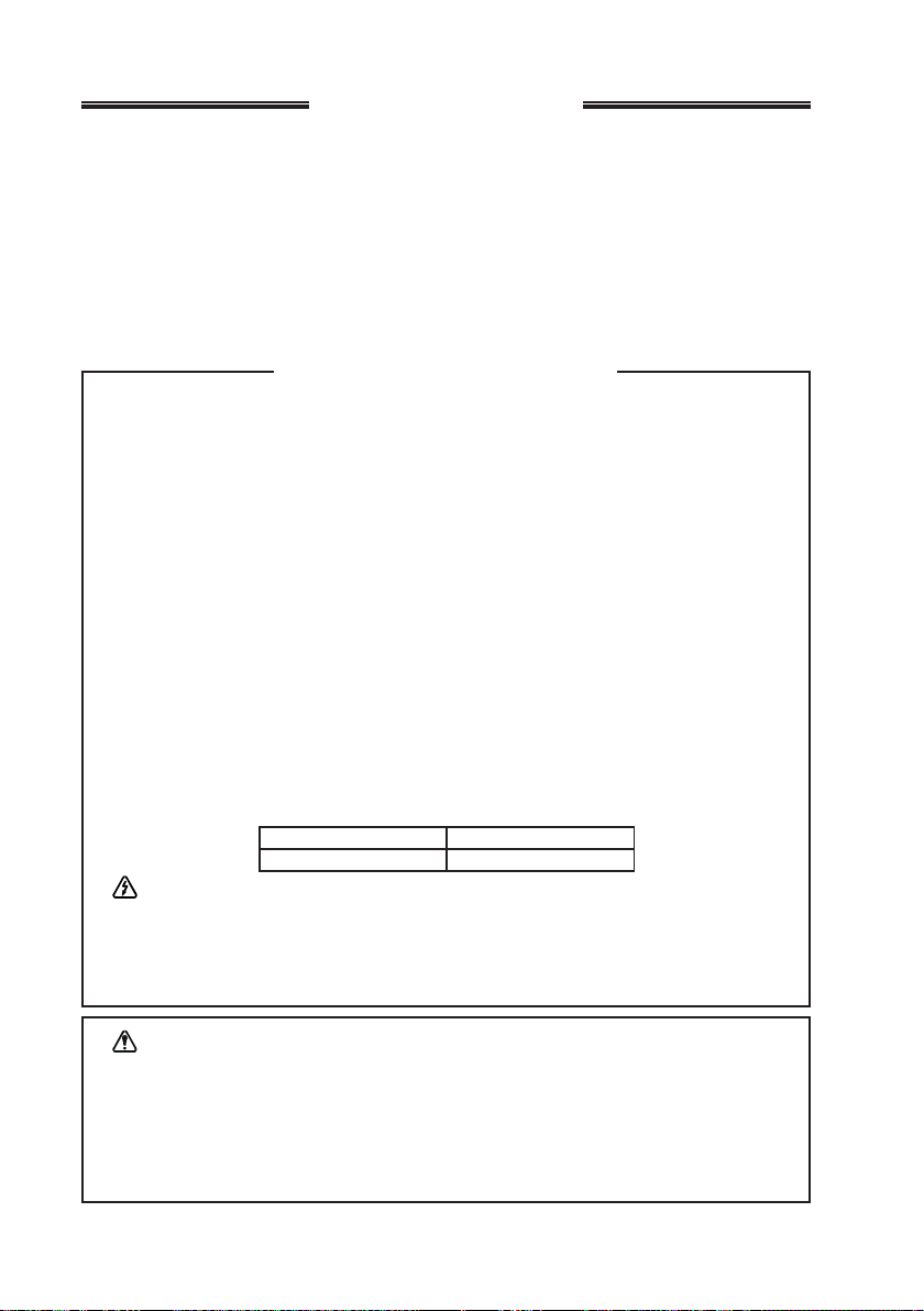
Unsafe Radiation Distance
VX-4204E VX-4207E
0.705 m 0.611 m
Warning!
The 50.0 V RF voltage (@25 W/50 Ω) is applied to the antenna terminal of the
transciver while transmitting.
Do not touch the TX RF section absolutely while transmitting.
Caution: This radio can become hot.
Use this transceiver in the place where the temperature range is less than +60 ºC.
Do not operate the radio continuously in transmission mode for longer than 7 minutes. Ensure enough standby/reception time for cool-down between transmission periods. Be sure that the TOT timer is correctly installed and properly working. Avoid
touching the rear bottom of the transceiver’s body while transmission.
INTRODUCTION
P1
P2
A
P3
P4
The VX-4200E Series are full-featured FM transceiver designed for flexible mobile
and base station business communications in the VHF or UHF Land Mobile bands.
These transceiver are designed for reliable business communications in a wide variety of applications with a wide range of operating capability provided by their leading-edge design.
The 501-channel memories can each be programmed with a 12-character channel
name. Important channel frequency data is stored in EEPROM and flash memory on
the CPU, and is easily programmable by dealers using a personal computer and the
VERTEX STANDARD VPL-1 Programming Cable and CE59 Software.
The pages which follow will detail the many advanced features provided on the VX-
4200E Series transceiver. After reading this manual, you may wish to consult with
your Network Administrator regarding precise details of the configuration of this
equipment for use in your application.
NOTICE !
There are no owner-serviceable parts inside the transceiver. All service jobs
must be referred to an authorized VERTEX STANDARD Service Representative. Consult your Authorized VERTEX STANDARD Dealer for installation of optional accessories.
ATTENTION IN CASE OF USE
This transceiver works on frequencies which
are not generally permitted.
For frequency allocation, apply for a licence at
your local spectrum management authority.
For actual usage contact your dealer or sales
shop in order to get your transceiver adjusted
to the allocated frequency range.
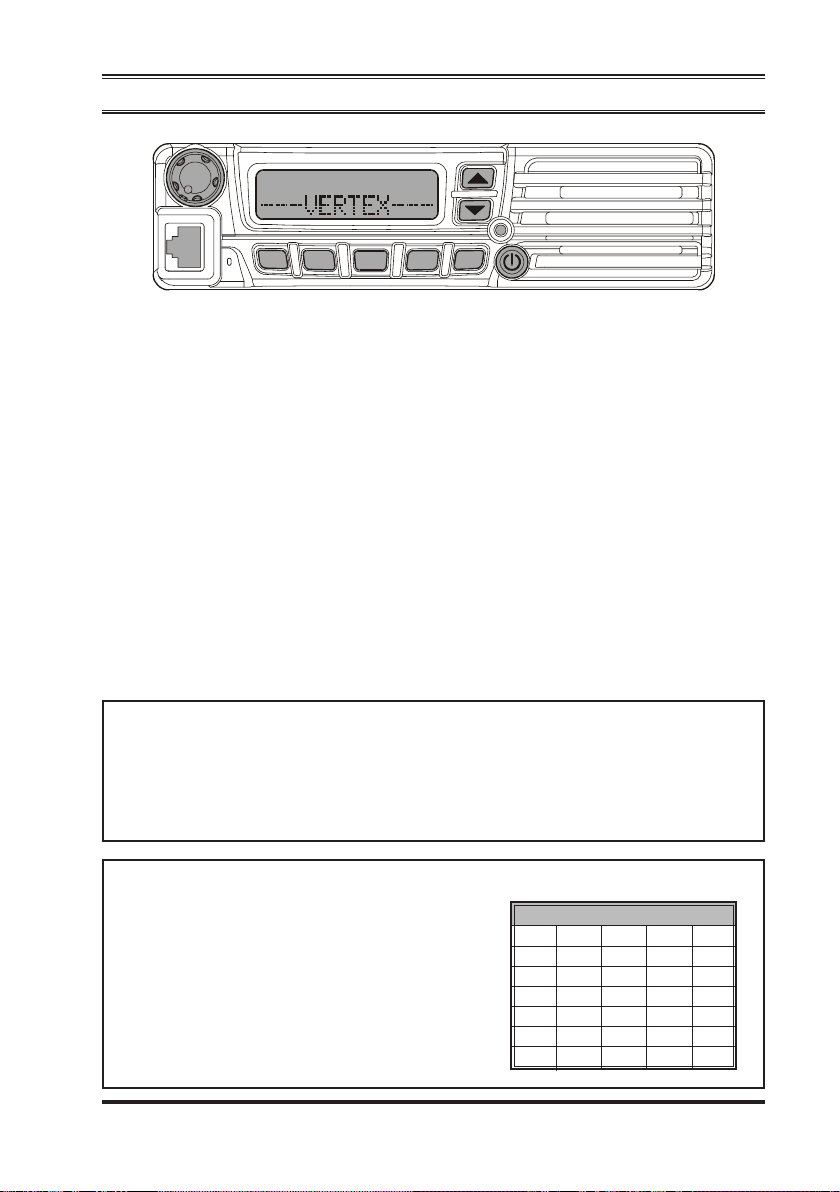
List of the practicable area
AUT BEL BGR CYP CZE
DEU DNK ESP EST FIN
FRA GBR GRC HUN IRL
ITA LTU LUX LVA MLT
NLD POL PR T R OM SVK
SV N SWE C HE ISL LIE
NOR
VX-4200E SERIES OPERATING MANUAL 1
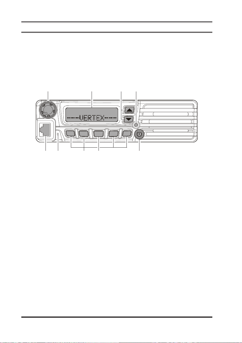
CONTROLS & CONNECTORS
Front Panel
Important! - All buttons located on the Front Panel are Programmable Function (PF)
Buttons, configured according to your network requirements and programmed by
your VERTEX STANDARD dealer. The instructions below describe a typicallyconfigured radio.
cji
P1
dfeg
VOL Knob
c
Turn this control clockwise to increase the volume.
Microphone Jack
d
Connect the microphone plug to this jack.
Emergency Microphone
e
The emergency microphone is located behind this small slit. When the emergency feature is activated, this microphone is enabled.
[P1] - [P1]
f
These buttons can be set up for special applications, such as High/Low power
selection, Monitor, Talk-Around, etc., as determined by your network requirements and programmed by your VERTEX STANDARD dealer.
Buttons (Programmable Function Buttons)
P2
k
P4
P3
A
h
[A]
g
Button (Programmable Function Button)
This button can be set up for special applications, such as High/Low power selection, Monitor, Talk-Around, etc., as determined by your network requirements
and programmed by your VERTEX STANDARD dealer.
VX-4200E SERIES OPERATING MANUAL2
CONTROLS & CONNECTORS
h
i
j
k
(POWER) Button
Press and hold in this button for 2 seconds to toggle the transceiver’s power “on”
and “off.”
BUSY/TX Indicator
Indicates transceiver’s Transmit/Receive Status
Steady Red: Transmitting in progress
Steady Green: Signaling Off
Blinking Green: Busy Channel/Squelch Off
[T]/[S]
Pressing either button changes the current channel (and displayed channel number or name). Holding in either button for more than 1.5 second causes the radio
to begin stepping (repeatedly) upward or downward through the channels.
Buttons (Programmable Function Buttons)
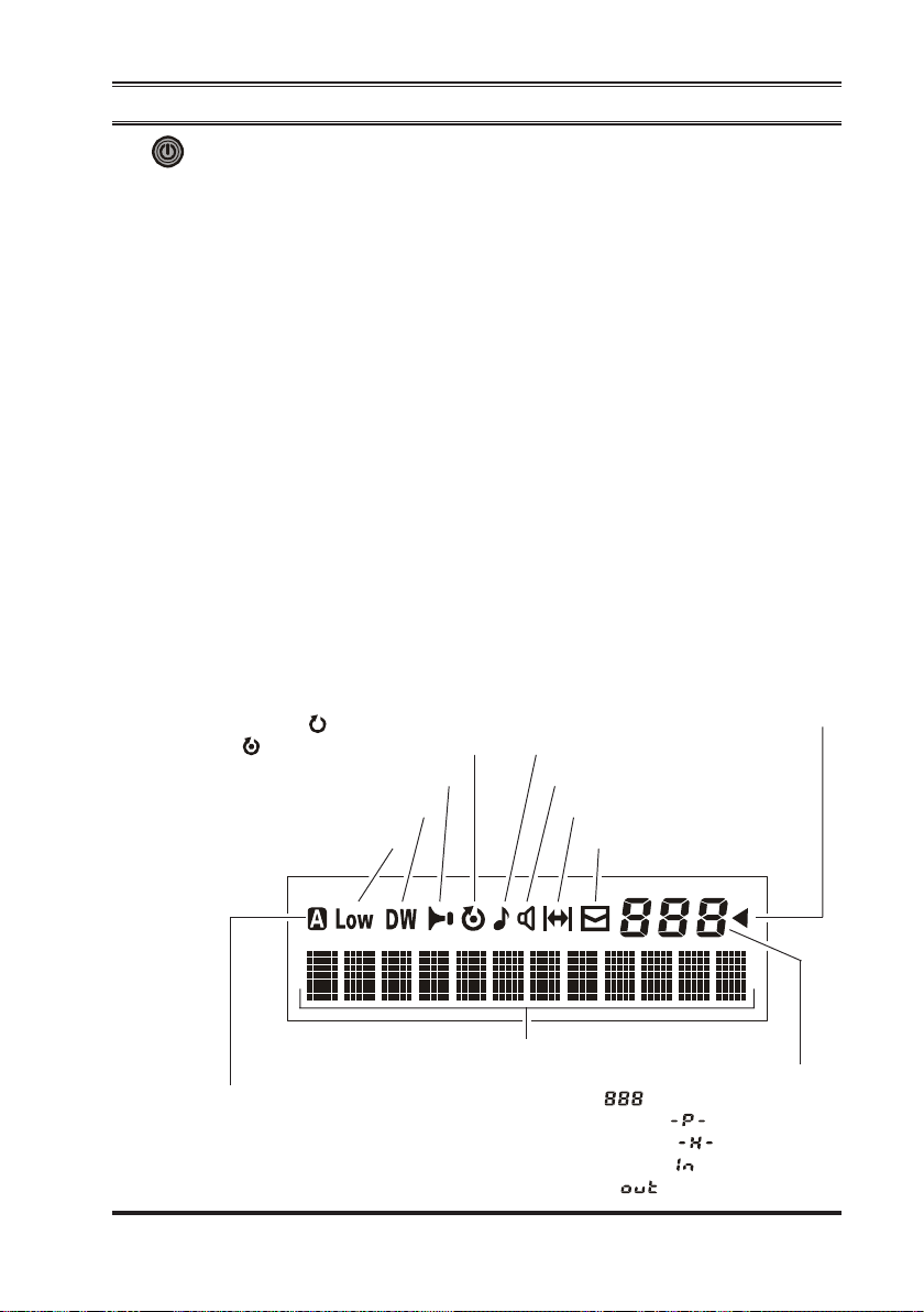
LCD (Liquid Crystal Display)
The display includes a 3-character numeric section showing Channel Group number or certain status indications (see below), a 12-character alpha-numeric section showing Channel name tags/identity information and error messages, and
an upper icon row displaying feature status.
: “Priority Scan” is activated
: “Scan” is activated
“Horn Alert” is enabled
“Dual Watch” is activated
Low Transmt Power Mode “ON”
“Call” indicator
Receiver Monitor
“Talk-Around” is enabled
“Group Scan” is enabled
“Voice Message” received
“AUX A” Port is activated
12 Character Alpha-numeric Display
: Channel Group Number
: ARTS “In Range”
: ARTS “Out of Range”
Sub-LCD
: Priority Channel
: Home Channel
VX-4200E SERIES OPERATING MANUAL 3
CONTROLS & CONNECTORS
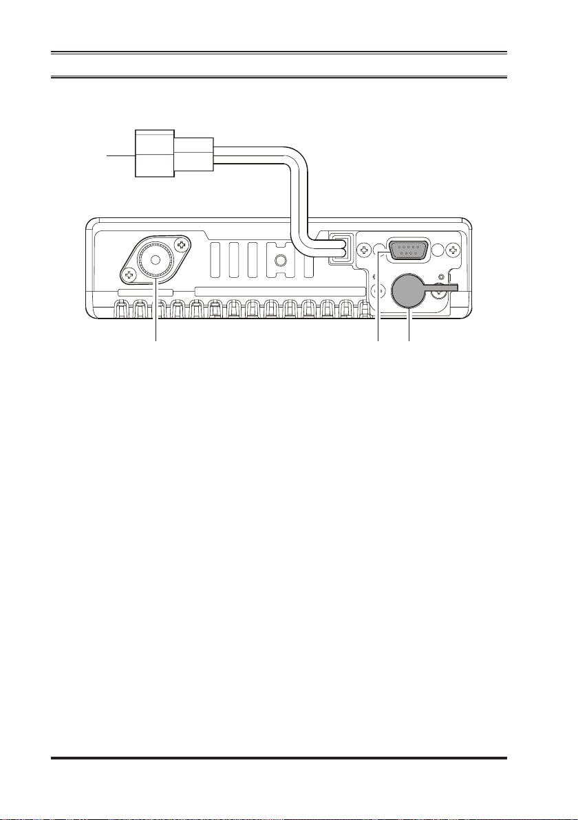
Rear Panel
c
def
13.6V DC Cable Pigtail with Connector
c
The supplied DC power cable must be connected to this 2-pin connector. Use
only the supplied fused cable, extended if necessary, for power connection.
Antenna Socket
d
The 50-Ohm coaxial feedline to the antenna must be connected here, using a
type-M (PL-259) plug.
D-Sub 15-Pin Accessory Connector
e
External TX audio line input, PTT (Push To Talk), Squelch, and external RX
audio line output signals may be obtained from this connector for use with accessories such as data transmission/reception modems, and external Channel control input etc.
External Speaker Jack
f
An external loudspeaker may be connected to this 2-contact, 3.5-mm mini-phone
jack.
Caution: Do not connect either wire of this line to ground, and be certain that the
speaker has adequate capability to handle the audio output (12 W) from the
radio.
VX-4200E SERIES OPERATING MANUAL4

BASIC OPERATION OF THE TRANSCEIVER
Important! - Before turning on the radio the first time, confirm that the power connections have been made correctly and that a proper antenna is connected to the
antenna jack.
Switching Power ON/OFF
Press and hold in the (POWER) button for 2 seconds to turn the radio on.
The display will become illuminated.
Press the [T]/[S] button to choose the desired operating channel. A channel
name will appear on the display. If you want to select an operating channel from
a different group, press the PF (Programmable Function) button which is programmed to the Group Up/Down feature to select the group you want before
selecting the operating channel. See page 7 for more information on the Programmable Function keys.
Setting the Volume
Turn the VOL knob clockwise to increase the volume, and counterclockwise to
decrease it.
Transmitting
To transmit, monitor the channel and make sure it is clear.
Press the PF button which is programmed to the Monitor feature to listen for
channel activity.
When receiving a call, transmit only after the incoming call ends. The radio
cannot receive a call and transmit simultaneously.
Press the PTT switch.
If the channel is clear, the BUSY/TX indicator will glow red. The radio is now
transmitting. While holding in the PTT switch, speak across the face of the microphone in a clear and normal voice. For best transmission, hold the microphone
about 1-1/2 to 2 inches away from your mouth. Release the PTT switch to receive.
If the Busy Channel Lockout feature has been programmed on a channel, the
radio will not transmit when a carrier is present. Instead, the radio will generate
a short beep three times and indicate “*
PTT switch and wait for the channel to be clear of activity.
If CTCSS or Digital Coded Squelch (DCS) Lockout has been programmed on a
channel, the radio can transmit only when there is no carrier being received or
when the carrier being received includes the correct CTCSS tone or DCS code.
ERRORERROR
ERROR *” on the display. Release the
ERRORERROR
VX-4200E SERIES OPERATING MANUAL 5

BASIC OPERATION OF THE TRANSCEIVER
Automatic Time-Out Timer
If the selected channel has been programmed for automatic time-out, you must limit
the length of each transmission. While transmitting, a beep will sound 10 seconds
before time-out. Another beep will sound just before the deadline; the red “TX”
indicator will disappear and transmission will cease soon thereafter. To resume transmitting, you must release the PTT switch and wait for the “penalty timer” to expire
(if you press the PTT switch before this timer expires, the timer restarts, and you will
have to wait another “penalty” period)
Key Lock
In order to prevent accidental frequency change or inadvertent transmission, various
aspects of the VX-4200E’s keys, and PTT switch, may be locked out. The precise
lockout configuration may be configured using the “User Set” (Menu) mode. See
page 16 for detail.
To activate the Locking feature, press and hold in the [P4] key while turning the
radio on. To disable the Locking feature, repeat this power-on procedure.
VX-4200E SERIES OPERATING MANUAL6
 Loading...