

VX-4100E
OPERATING MANUAL
SERIES
TX/BUSY
P2P1
1234
A
VERTEX STANDARD CO., LTD.
4-8-8 Nakameguro, Meguro-Ku, Tokyo 153-8644, Japan
VERTEX STANDARD
US Headquarters
10900 Walker Street, Cypress, CA 90630, U.S.A.
YAESU UK LTD.
Unit 12, Sun Valley Business Park, Winnall Close
Winchester, Hampshire, SO23 0LB, U.K.
VERTEX STANDARD HK LTD.
Unit 5, 20/F., Seaview Centre, 139-141 Hoi Bun Road,
Kwun Tong, Kowloon, Hong Kong
VERTEX STANDARD (AUSTRALIA) PTY., LTD.
Normanby Business Park, Unit 14/45 Normanby Road
Notting Hill 3168, Victoria, Australia
Congratulations!
You now have at your fingertips a valuable communications tool: a VERTEX STANDARD
two-way radio! Rugged, reliable and easy to use, your VERTEX STANDARD radio will keep
you in constant touch with your colleagues for years to come, with negligible maintenance
downtime.
Please take a few minutes to read this manual carefully. The information presented here will
allow you to derive maximum performance from your radio, in case questions arise later on.
We’re glad you joined the VERTEX STANDARD team. Call on us anytime, because communications is our business. Let us help you get your message across.
SAFETY/WARNING INFORMATION
WARNING - DO NOT operate the VX-4100E radio when any person(s) (bystanders)
outside the vehicle are within the distances shown in the chart at the bottom of this
section.
Safety Training information:
Antennas used for this transmitter must not exceed an antenna gain of 0 dBd. The radio
must be used in vehicle-mount configurations with a maximum operating duty factor
not exceeding 50 %, in typical Push-to-Talk configurations.
This radio is restricted to occupational use, work related operations only where the
radio operator must have the knowledge to control the exposure conditions of its
passengers and bystanders by maintaining the minimum separation distance shown
below.
Antenna Installation:
For rear deck trunk installation, the antenna must be located at least the following
distance away from rear-seat passengers.
For roof top installations, the antenna must be placed in the center of the roof.
Unsafe Radiation Distance
VX-4104E VX-4107E
0.705 m 0.611 m
Warning!
The 50.0 V RF voltage (@25 W/50 Ω) is applied to the antenna terminal of the
transciver while transmitting.
Do not touch the TX RF section absolutely while transmitting.
Caution: This radio can become hot.
Use this transceiver in the place where the temperature range is less than +60 ºC.
Do not operate the radio continuously in transmission mode for longer than 7 minutes. Ensure enough standby/reception time for cool-down between transmission periods. Be sure that the TOT timer is correctly installed and properly working. Avoid
touching the rear bottom of the transceiver’s body while transmission.
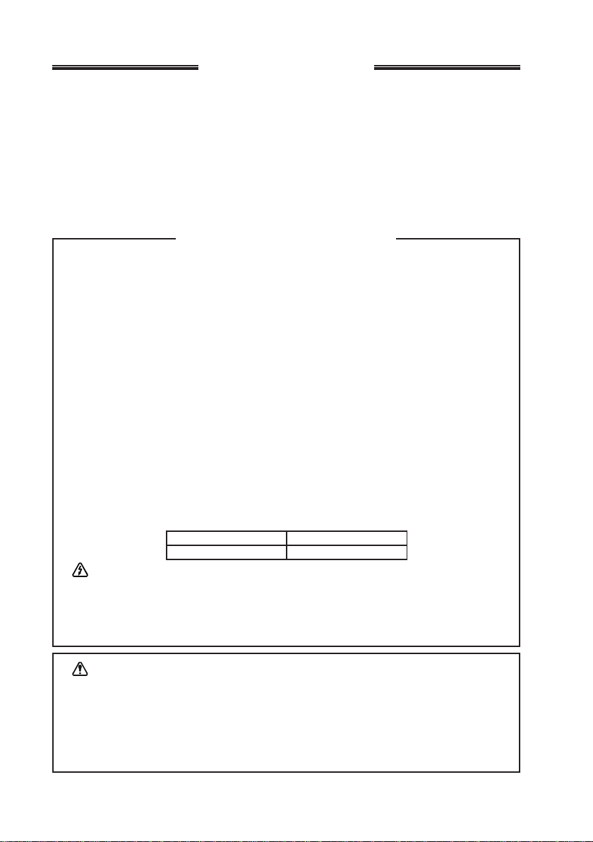
INTRODUCTION
TX/BUSY
1234
A
P2P1
The VX-4100E Series are full-featured FM transceiver designed for flexible mobile
and base station business communications in the VHF or UHF Land Mobile bands.
These transceiver are designed for reliable business communications in a wide variety of applications with a wide range of operating capability provided by their leading-edge design.
Important channel frequency data is stored in EEPROM and flash memory on the
CPU, and is easily programmable by dealers using a personal computer and the VERTEX STANDARD VPL-1 Programming Cable and CE59 Software.
The pages which follow will detail the many advanced features provided on the VX-
4100E Series transceiver. After reading this manual, you may wish to consult with
your Network Administrator regarding precise details of the configuration of this
equipment for use in your application.
NOTICE !
There are no owner-serviceable parts inside the transceiver. All service jobs
must be referred to an authorized VERTEX STANDARD Service Representative. Consult your Authorized VERTEX STANDARD Dealer for installation of optional accessories.
ATTENTION IN CASE OF USE
This transceiver works on frequencies which
are not generally permitted.
For frequency allocation, apply for a licence at
your local spectrum management authority.
For actual usage contact your dealer or sales
shop in order to get your transceiver adjusted
to the allocated frequency range.
List of the practicable area
AUT BEL BGR CYP CZE
DEU DNK ESP EST FIN
FRA GBR GRC HUN IRL
ITA LTU LUX LVA MLT
NLD POL PR T R OM SVK
SV N SWE C HE ISL LIE
NOR
VX-4100E SERIES OPERATING MANUAL 1
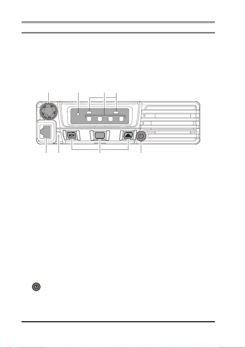
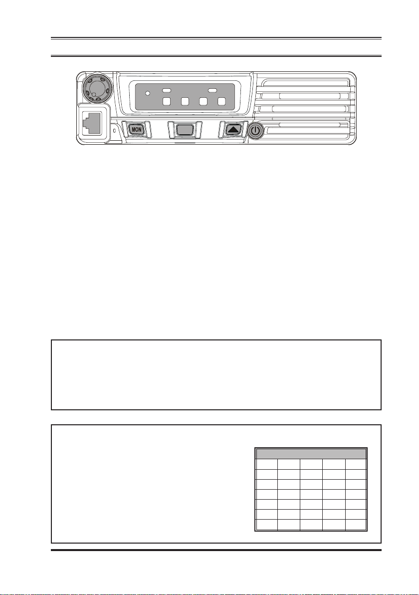
CONTROLS & CONNECTORS
Front Panel
Important! - All buttons located on the Front Panel are Programmable Function (PF)
Buttons, configured according to your network requirements and programmed by
your VERTEX STANDARD dealer. The instructions below discribe a typically-configured radio.
cjhi
TX/BUSY
1234
A
P2P1
dfeg
VOL Knob
c
Turn this control clockwise to increase the volume.
Microphone Jack
d
Connect the microphone plug to this jack.
Emergency Microphone
e
The emergency microphone is located behind this small slit. When the emergency feature is activated, this microphone is enabled.
[
MON], [A],
f
These buttons can be set up for special applications, such as High/Low power
selection, Monitor, Talk-Around, etc., as determined by your network requirements and programmed by your VERTEX STANDARD dealer.
[
SS
S] Buttons (Programmable Function Buttons)
SS
g
(POWER) Button
Press and hold in this button for 2 seconds to toggle the transceiver’s power “on”
and “off.”
VX-4100E SERIES OPERATING MANUAL2

CONTROLS & CONNECTORS
TX/BUSY Indicator
h
Indicates the transceiver’s Transmit/Receive Status.
Steady Red: Transmitting in progress
Steady Green: Signaling Off
Blinking Green: Busy Channel/Squelch Off
Channel Number Indicator
i
Indicates the operating channel.
Transceiver Status Indicator
j
The “P1” and “P2” indicators show current transceiver status, which can be
customized via programming by your VERTEX STANDARD dealer to meet
your communications/network requirements. The possible “P1” and “P2” dis-
plays are explained below.
)
INDICATOR
P1 P2
This indicator blinks when CTCSS- or DCScontrolled squelch is disabled. The indicator is
Illuminated constantly while the audio is passing normally.
Illuminates the indicator when the operating
channel is selected on the SCAN channel.
Illuminates the indicator when the radio recalls
the alternate channel list.
Illuminates the indicator when the radio’s transmitter is set to the “Low Power” mode.
Illuminates the indicator when the “Talk Around”
function is activated.
Illuminates the indicator when the “Voice
Scrambler” function is disabled temporarily.
Illuminates the indicator when the “Emergency”
feature is activated.
Illuminates the indicator when you recall the
Home group/channel.
Illuminates the indicator when the “Horn Alert”
feature is activated.
Illuminates the indicator when the radio is
turned to a PA amplifier.
Illuminates the indicator when the front panel’s
keys are locked.
Illuminates the indicator when the output port
on the Accessory Connector is turned to “ON.”
Blinks the indicator while the received audio is
recording. Illuminates the indicator when the
voice recording is completed.
STATUS DESCRIPTION
MONI
SCAN Channel
+4 CH
LOW
TA (Talk Around
Encryption Disable
(
Requires optional Unit
Emergency
HOME
Horn Alert
Public Adress
Key Lock
EXT ACC
REC/PLAY
)
VX-4100E SERIES OPERATING MANUAL 3
CONTROLS & CONNECTORS
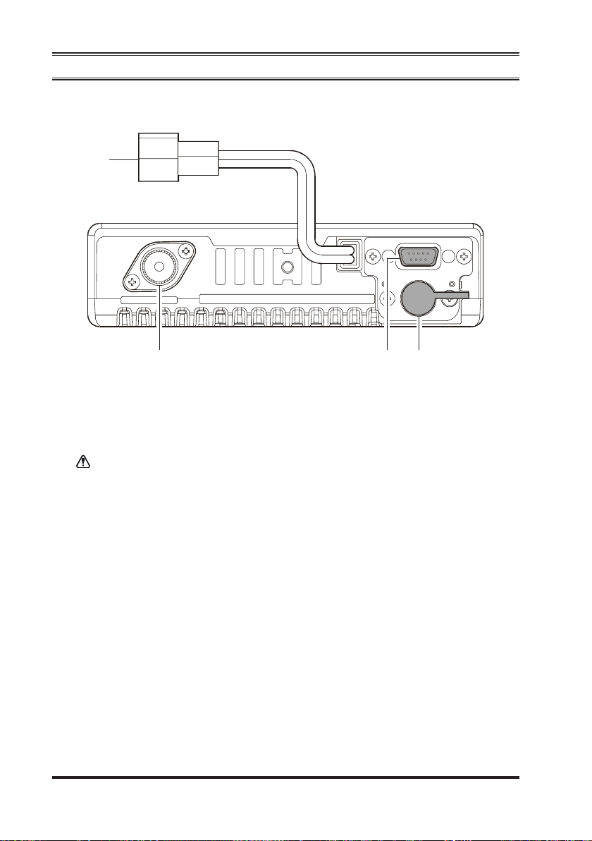
Rear Panel
c
def
13.2V DC Cable Pigtail with Connector
c
The supplied DC power cable must be connected to this 2-pin connector. Use
only the supplied fused cable, extended if necessary, for power connection.
Replace only with the same or equivalent type fuse.
Antenna Socket
d
The 50-Ohm coaxial feedline to the antenna must be connected here, using a
type-M (PL-259) plug.
D-Sub 15-Pin Accessory Connector
e
External TX audio line input, PTT (Push To Talk), Squelch, and external RX
audio line output signals may be obtained from this connector for use with accessories such as data transmission/reception modems, and external Channel control input etc.
External Speaker Jack
f
An external loudspeaker may be connected to this 2-contact, 3.5-mm mini-phone
jack.
Caution: Do not connect either wire of this line to ground, and be certain that the
speaker has adequate capability to handle the audio output (12 W) from the
radio.
VX-4100E SERIES OPERATING MANUAL4
 Loading...