

Vertex Standard VX-4000 Series Operating Manual
VX-4000
OPERATING MANUAL
MANUAL DE OPERACIÓN
POWER
VERTEX STANDARD CO., LTD.
4-8-8 Nakameguro, Meguro-Ku, Tokyo 153-8644, Japan
VERTEX STANDARD
US Headquarters
17210 Edwards Rd., Cerritos, CA 90703, U.S.A.
International Division
8350 N.W. 52nd Terrace, Suite 201, Miami, FL 33166, U.S.A.
YAESU EUROPE B.V.
P.O. Box 75525, 1118 ZN Schiphol, The Netherlands
YAESU UK LTD.
Unit 12, Sun Valley Business Park, Winnall Close
Winchester, Hampshire, SO23 0LB, U.K.
YAESU GERMANY GmbH
Am Kronberger Hang 2, D-65824 Schwalbach, Germany
VERTEX STANDARD HK LTD.
Unit 5, 20/F., Seaview Centre, 139-141 Hoi Bun Road,
Kwun Tong, Kowloon, Hong Kong

English
Congratulations!
You now have at your fingertips a valuable communications tool - a two-way
radio! Rugged, reliable and easy to use, your radio will keep you in constant
touch with your colleagues for years to come, with negligible maintenance down time.
Please take a few minutes to read this manual carefully. The information presented here
will allow you to derive maximum performance from your radio. After reading it, keep
the manual handy for quick reference, in case questions arise later on.
We’re glad you joined the team. Call on us any time, because our business is
communications. Let us help you get your message across.
NOTICE
There are no user-serviceable points inside this transceiver. All service jobs must
be referred to your Authorized Service Center or Network Administrator.
Safety / Warning Information
WARNING - DO NOT operate the VX-4000V/U radio when someone (bystand-
ers) outside the vehicle is within following range.
Safety Training information:
Antennas used for this transmitter must not exceed an antenna gain of 0 dBd. The
radio must be used in vehicle-mount configurations with a maximum operating duty
factor not exceeding 50%, in typical Push-to-Talk configurations.
This radio is restricted to occupational use, work related operations only where the
radio operator must have the knowledge to control the exposure conditions of its
passengers and bystanders by maintaining the minimum separation distance of
following range.
Failure to observe these restrictions will result in exceeding the FCC RF exposure
limits.
Antenna Installation:
For rear deck trunk installation, the antenna must be located at least following range
away from rear seat passengers in order to comply with the FCC RF exposure
requirements.
For roof top installation, the antenna must be placed in the center of the roof.
Radiated frequency and Distance
VX-4000V VX-4000U (A) VX-4000U (D) VX-4000U (F)
3.27 Feet
(0.997 m)
2.83 Feet
(0.864 m)
2.67 Feet
(0.814 m)
2.58 Feet
(0.788 m)
VX-4000 Operating Manual
POWER
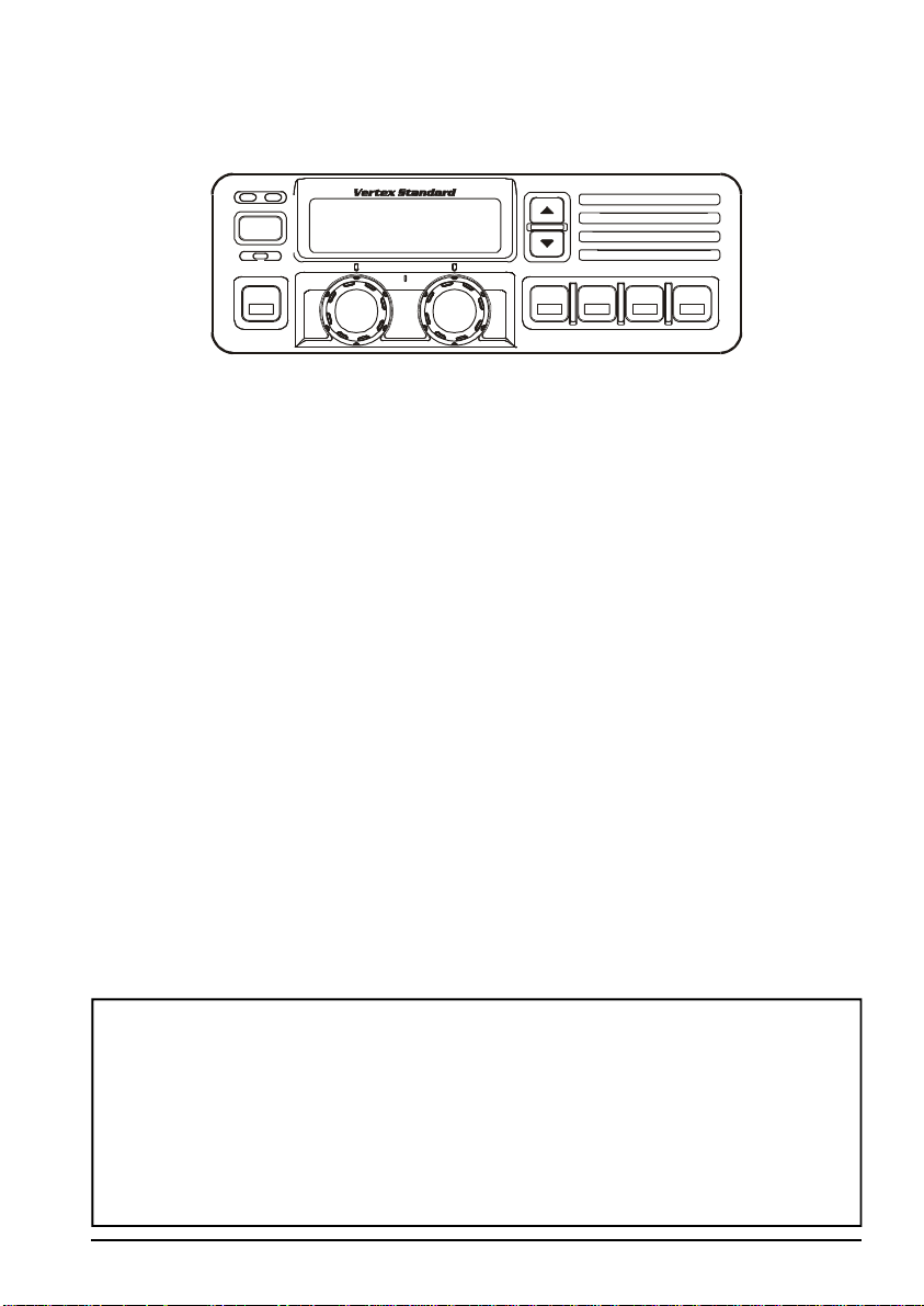
The VX-4000 Series are full-featured FM transceivers designed for flexible mobile and
base station business communications in the VHF (50/25 Watts: programmable) and UHF
(40/25 Watts: programmable) Land Mobile Bands. Each model is designed for reliable
business communications in a wide variety of applications, with a wide range of operating
capability provided by its leading-edge design.
The 250-channels memories can each be programmed with a 8-character channel name.
Important channel frequency data is stored in EEPROM and flash memory on the CPU,
and is easily programmable by dealers using a personal computer and the VERTEX STANDARD CT-71 Programming Cable and CE35 Software.
The pages which follow will detail the many advanced features provided on the VX-4000
transceiver. After reading this manual, you may wish to consult with your Network Administrator regarding precise details of the configuration of this equipment for use in your
application.
For North American Users Regarding 406 MHz Guard Band
The U.S. Coast Guard and National Oceanographic and Atmospheric Administration
have requested the cooperation of the U.S. Federal Communications Commission in
preserving the integrity of the protected frequency range 406.0 to 406.1 MHz, which is
reserved for use by distress beacons. Do not attempt to program this apparatus, under
any circumstances, for operation in the frequency range 406.0 - 406.1 MHz if the
apparatus is to be used in or near North America.
VX-4000 Operating Manual
Page 1
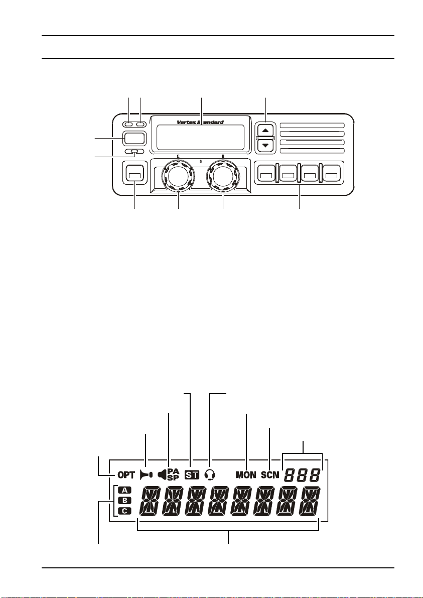
Front Panel
ƒ‚„
…
‡
ˆ‰Š
CONTROLS & CONNECTORS
•
POWER
†
A
POWER Button
•
Press the button to turn the transceiver ON and OFF.
TX Indicator
‚
This lamp glows red when the radio is transmitting.
BUSY Indicator
ƒ
This lamp glows green when the channel is busy.
Liquid Crystal Display
„
The display include an 8-character alpha-numeric section showing channel and group
names, status and identity information, and error messages. Additional indicators on
the display show priority channel assignments and scan include / exclude selection.
This channel on "INTERCOM" ListThis channel on "SELECTABLE TONE" List
"CHANNEL RECALL" List
This channel on "HORN ALERT" List
This channel on
"OPTION" List
Receiver MonitorThis channel on "PUBLIC ADDRESS" or
This channel on "SCAN" List
Channel Group Number
This channel on "AUX A/B/C" List
Page 2
8 Character Alpha-numeric Invertible Display
VX-4000 Operating Manual
CONTROLS & CONNECTORS
p/q Button
…
Pressing these buttons changes the current group (and displayed group number or
name). Holding this button for more than 1/2 second causes the function to repeat.
HOME Indicator
†
This lamp glows orange when incorrect position at the setting of CE35.
Programmable Function Button (PF button)
‡
This button can be set up for special applications, such as high/low power selection,
monitor, dimmer, talk-around, and call alert function, as determined by your network
requirements and programmed by your VERTEX STANDARD dealer.
VOLUME Knob
ˆ
This knob sets the volume of the receiver.
CHANNEL Selector Knob
‰
This knob select the operating channel.
Programmable Function Button (PF button)
Š
This button can be set up for special applications, such as high/low power selection,
monitor, dimmer, talk-around, and call alert function, as determined by your network
requirements and programmed by your VERTEX STANDARD dealer.
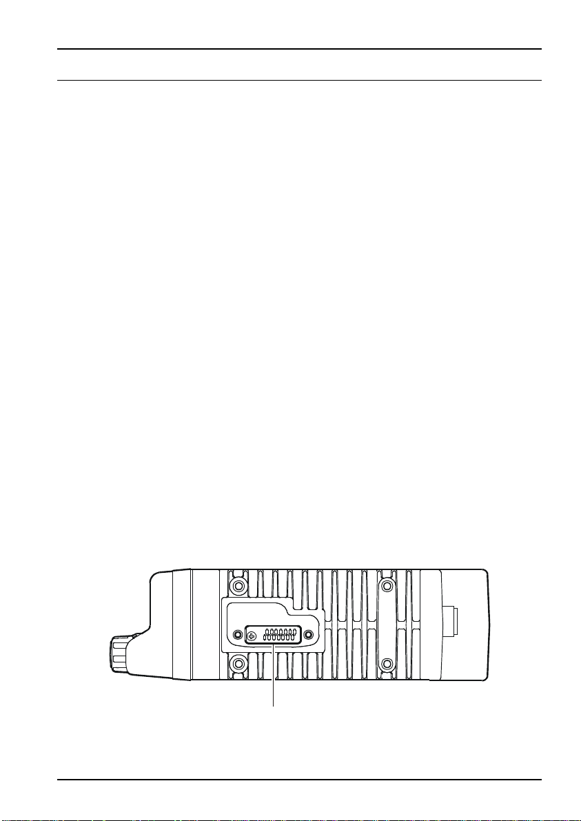
Side Panel
Microphone Jack (It is on both sides.)
Connect the microphone plug to this jack.
Microphone Jack
VX-4000 Operating Manual
Page 3
CONTROLS & CONNECTORS
ƒ‚•
„
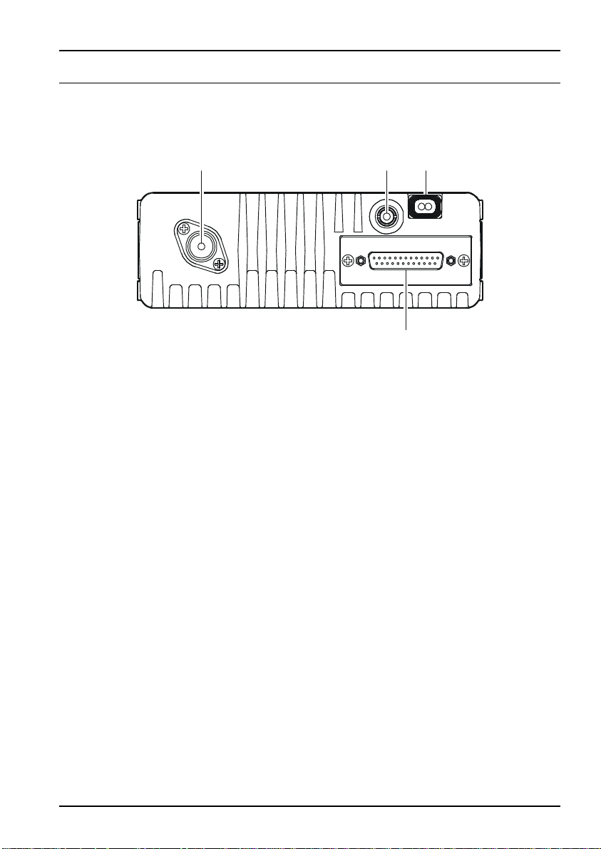
REAR (Heatsink)
Antenna Socket
À
The 50-ohm coaxial feedline to the antenna must be connected here, using a type-M
(PL-259) plug.
External Speaker Jack
Á
An external loudspeaker may be connected to this 2-contact, 3.5-mm mini-phone
jack.
Caution: Do not connect this line to ground, and be certain that the speaker has
adequate capability to handle the audio output from the VX-4000.
13.8-V DC Cable Pigtail w/Connector
Â
The supplied DC power cable must be connected to this 2-pin connector. Use only
the supplied fused cable, extended if necessary, for power connection.
DSUB 25-Pin Accessory Connector
Ã
External TX audio line input, PTT (Push To Talk), Squelch, and external RX audio
line output signal may be obtained from this connector for use with accessories such
as data transmission/reception modems, ets.
Page 4
VX-4000 Operating Manual

BASIC OPERATION OF THE TRANSCEIVER
Important! - Before turning on the radio the first time, confirm that the power connections have been made correctly and that a proper antenna is connected to the antenna jack.
Switching Power ON/OFF
Push the POWER switch turn on the radio. The display will become illuminated. The
radio will start up on the last channel used prior to shut-down during the previous
operating session.
Turn the CHANNEL selector knob to choose the desired operating channel. A channel name will appear on the display. If you want to select the operating channel from a
different Memory Channel Group, press the UP (p) or DOWN (q) button to select
the Memory Channel Group you want before selecting the operating channel.
Setting the Volume
Turn the VOLUME knob clockwise to increase the volume, and counterclockwise to
decrease it. If no signal is present, press and hold in the MON button more than 1/2
seconds; background noise will now be heard, and you may use this to set the VOL-
UME knob for the desired audio level. Press and hold the MON button more than 1/2
seconds to quiet the noise and resume normal (quiet) monitoring.
Transmitting
To transmit, wait until the “BUSY” indicator is off (the channel is not in use), and
press the PTT (Push-To-Talk) switch on the side of the microphone (the “TX” indicator will appear or the “TX” indicator will glow red). While holding in the PTT switch,
speak across the face of the microphone in a clear, normal voice level, and then release
the PTT switch to receive.
Selecting Groups and Channels
m Press the UP (p) or DOWN (q) button (repeatedly, if necessary) to select a
different group of channels.
m Turn the CHANNEL selector knob to select a different channel within the current
group.
Automatic Time-Out Timer
If the selected channel has been programmed for automatic time-out, you must limit
the length of each transmission. While transmitting, a beep will sound five seconds
before time-out. Another beep will sound just before the deadline; the “TX” indicator
will disappear and transmission will cease soon thereafter. To resume transmitting,
you must release the PTT and wait for the “penalty timer” to expire (if you press the
PTT before this timer expires, the timer restarts, and you will have to wait another
“penalty” period)
VX-4000 Operating Manual
Page 5
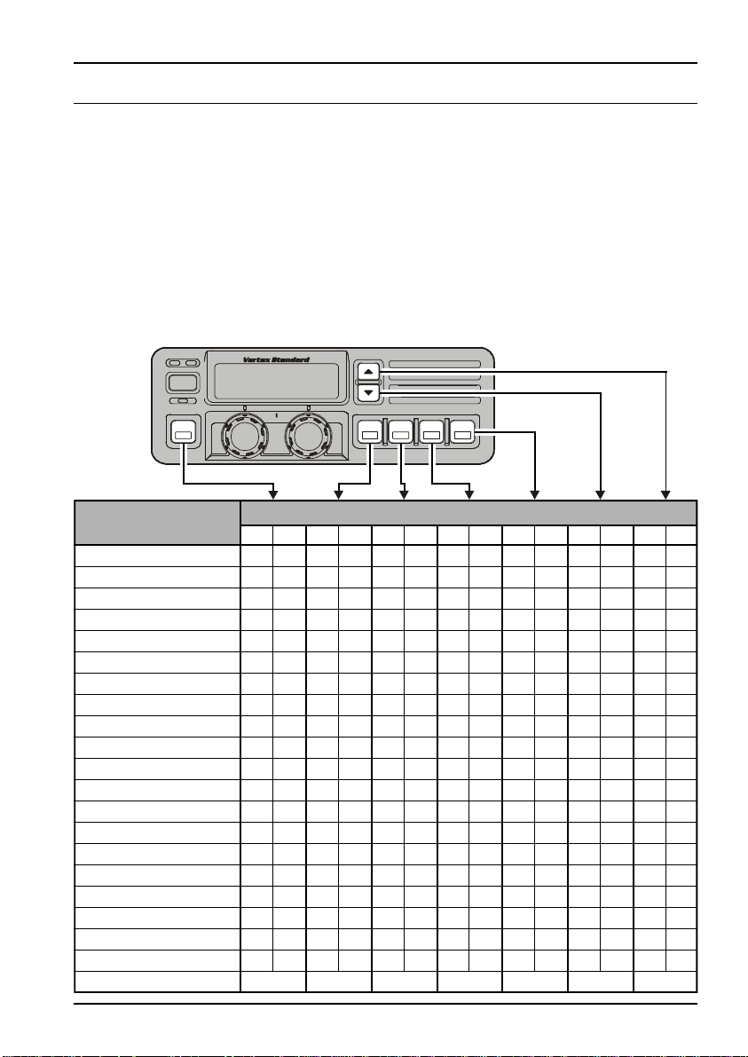
ADVANCED OPERATION
Programmable Function Button (PF button)
The VX-4000 includes the seven Programmable Function Buttons (PF button).
The PF button functions can be customized, via programming by your VERTEX STANDARD dealer, to meet your communications/network requirements. Some features may
require the purchase and installation of optional internal accessories. The possible PF
button programming features are illustrated at the below, and their functions are explained
on page 8.
For further details, contact your VERTEX STANDARD dealer. For future reference, check
the box next to each function that has been assigned to the PF button on your particular
radio, and keep it handy.
POWER
Functions
None
SCAN (SCN)
Dual Watch
Call/Reset
Talk-Around (TA)
Alpha Numeric (A/N)
DIMMER (DIM)
Emergency (EMG)
Horn Alert (HA)
Home Channel (HOM)
Intercom (IC)
Low Power (LOW)
GRP UP
GRP DWN
CH UP
CH DWN
AUX A
AUX B
AUX C
Public Address (PA)
Monitor (MON)
Page 6
<1.5 sec
>1.5 sec
Programmable Function Button (PF button)
<1.5 sec
>1.5 sec
<1.5 sec
>1.5 sec
<1.5 sec
>1.5 sec
<1.5 sec
>1.5 sec
VX-4000 Operating Manual
<1.5 sec
>1.5 sec
<1.5 sec
>1.5 sec
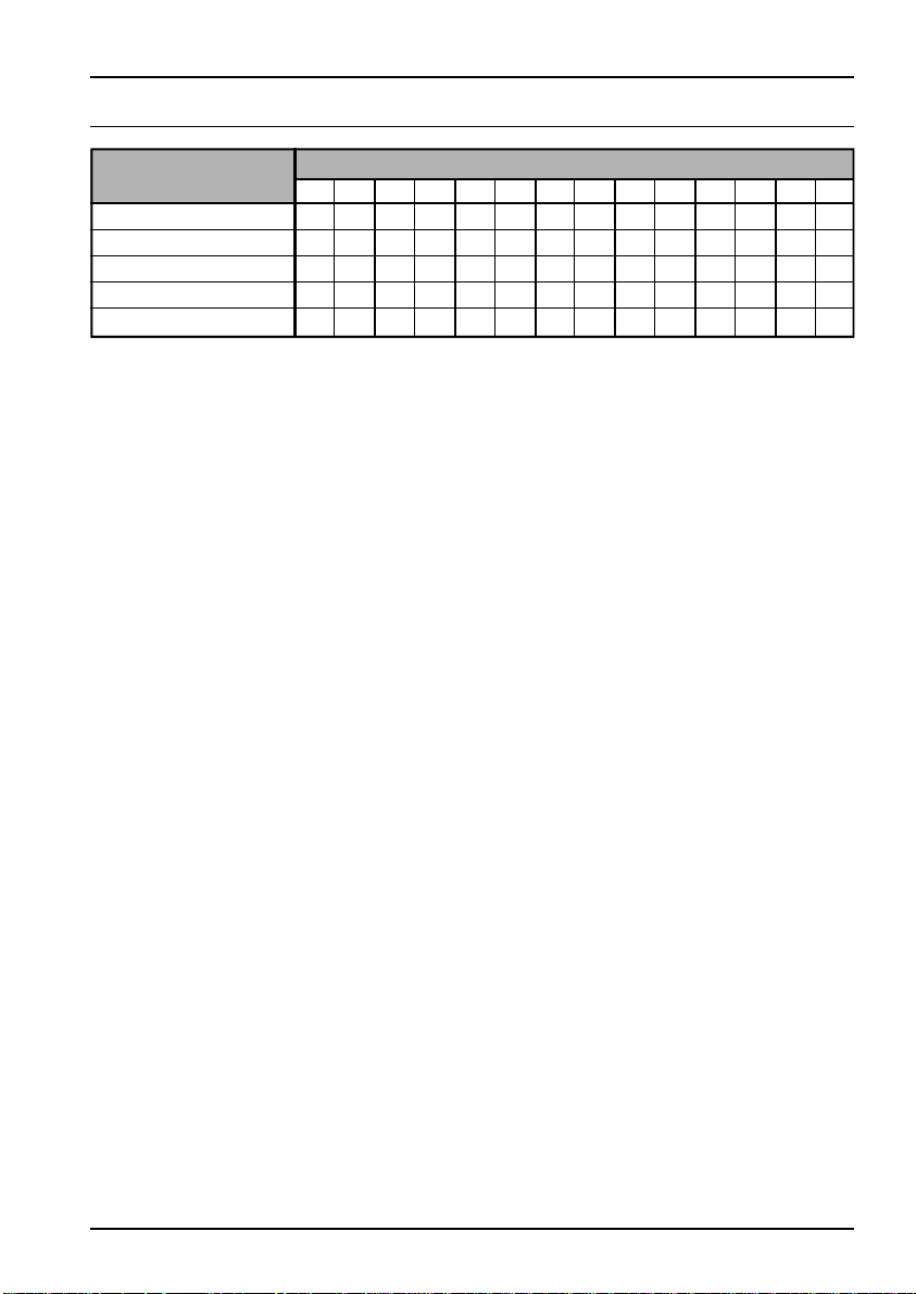
ADVANCED OPERATION
Functions
RCL
Selectable Tone (ST)
SP*
Squelch Level (SQL)
Encryption** (OPT)
* requires RMK-4000 ** requires Encryption Unit
<1.5 sec
>1.5 sec
Programmable Function Button (PF button)
<1.5 sec
>1.5 sec
<1.5 sec
>1.5 sec
<1.5 sec
>1.5 sec
<1.5 sec
>1.5 sec
<1.5 sec
>1.5 sec
Channel Scan
The Scanning feature is used to monitor multiple signals programmed into the transceiver. While scanning, the transceiver will check each channel for the presence of a
signal, and will stop on a channel if a signal is present.
To activate scanning:
m Press the assigned PF button of the “Scan” momentarily to activate scanning.
m The scanner will search the channels, looking for active ones; it will pause each
time it finds a channel on which someone is speaking.
To stop scanning
m Press the assigned PF button of the “Scan”.
m Operation will revert to the channel to which the CHANNEL selector knob is set.
Note:Your dealer may have programmed your radio to stay on one of the following
channels if you press the PTT switch during scanning pause:
Current channel (“Talk Back”)
r
“Last Busy” channel
r
“Priority” channel
r
“Home” channel
r
“Scan Start” channel
r
<1.5 sec
>1.5 sec
Dual Watch
The Dual Watch feature is similar to the Scan feature, except that only two channels
are monitored:
r The current operating channel; and
r The “Priority” channel.
To activate Dual Watch:
m Press the assigned PF button of the “Dual Watch”.
m The scanner will search the two channels; it will pause each time it finds a channel
on which someone is speaking.
To stop Dual Watch:
m Press the assigned PF button of the “Dual Watch”.
m Operation will revert to the channel to which the CHANNEL selector knob is set.
VX-4000 Operating Manual
Page 7
 Loading...