

Page 1
Condor
Platform Module.
Hardware
Reference
Manual
REV. October 2017
(VL-EPU-4460)
Intel Core* 6xxx-based
Embedded Processing Unit with
SATA, Dual Ethernet, USB,
Digital I/O, Serial, Video, Mini
PCIe Sockets, SPX, Trusted
Page 2

WWW.VERSALOGIC.COM
12100 SW Tualatin Road
Tualatin, OR 97062-7341
(503) 747-2261
Fax (971) 224-4708
Copyright © 2017 VersaLogic Corp. All righ ts reserved.
Notice:
Although every effort has been made to ensure this document is error-free, VersaLogic makes no
representations or warranties with respect to this product and specifically disclaims any implied warranties
of merchantability or fitness for any particular purpose.
VersaLogic reserves the right to revise this product and associated documentation at any time without
obligation to notify anyone of such changes.
* Other names and brands may be claimed as the property of others.
ii VL-EPU-4460 Reference Manual
Page 3

Product Revision Notes
Revision 1.0 Initial Release
Support Page
The Condor Support Page contains additional information and resources for this product
including:
Operating system information and software drivers
Data sheets and manufacturers links for chips used in this product
BIOS information and upgrades
VersaTech KnowledgeBase
The VersaTech KnowledgeBase contains useful technical information about VersaLogic
products, along with product advisories.
Customer Support
If you are unable to solve a problem after reading this manual, visiting the product support page,
or searching the KnowledgeBase, contact VersaLogic Technical Support at (503) 747-2261.
VersaLogic support engineers are also available via e-mail at [email protected].
Repair Service
If your product requires service, you must obtain a Returned Material Authorization (RMA)
number by calling 503-747-2261. Be ready to provide the following information:
Your name, the name of your company, your phone number, and e-mail address
The name of a technician or engineer that can be contacted if any questions arise
The quantity of items being returned
The model and serial number (barcode) of each item
A detailed description of the problem
Steps you have taken to resolve or recreate the problem
The return shipping address
Warranty Repair All parts and labor charges are covered, including return shipping
charges for UPS Ground delivery to United States addresses.
Non-warranty Repair All approved non-warranty repairs are subject to diagnosis and labor
charges, parts charges and return shipping fees. Specify the shipping
method you prefer and provide a purchase order number for invoicing
the repair.
Note: Mark the RMA number clearly on the outside of the box before returning.
VL-EPU-4460 Reference Manual iii
Page 4

Cautions
Electrostatic discharge (ESD) can damage circuit boards, disk drives, and other
not slide the board over any surface.
After removing the board from its protective wrapper, place the board on a grounded,
static-free surface, component side up. Use an antistatic foam pad if available.
The board should also be protected inside a closed metallic antistatic envelope during
shipment or storage.
Avoid touching the exposed circuitry with your fingers when handling the board. Though
defaults.
All mounting standoffs should be connected to earth ground (chassis ground). This
provides proper grounding for EMI purposes.
Electrostatic Discharge
Note: The exterior coating on some metallic antistatic bags is sufficiently conductive to cause excessive
battery drain if the bag comes in contact with the bottom side of the Condor.
Handling Care
CAUTION:
components.The circuit board must only be handled at an ESD workstation. If an
approved station is not available, some measure of protection can be provided by
wearing a grounded antistatic wrist strap. Keep all plastic away from the board, and do
CAUTION:
it will not damage the circuitry, it is possible that small amounts of oil or perspiration on
the skin could have enough conductivity to cause the contents of CMOS RAM to
become corrupted through careless handling, resulting in CMOS resetting to factory
Earth Ground Requirement
CAUTION:
iv VL-EPU-4460 Reference Manual
Page 5

Contents
Cautions ............................................................................................................................. iv
Electrostatic Discharge ......................................................................................... iv
Handling Care ....................................................................................................... iv
Earth Ground Requirement ................................................................................... iv
Introduction ................................................................................................................... 9
Features ............................................................................................................................. 10
Technical Specifications ................................................................................................... 10
Block Diagram .................................................................................................................. 11
Dimensions and Mounting ................................................................................................ 12
Condor Dimensions ............................................................................................. 12
Configuration and Setup ............................................................................................. 13
Initial Configuration ......................................................................................................... 13
Basic Setup ....................................................................................................................... 13
BIOS Setup Utility ............................................................................................................ 14
Default BIOS Setup Values ................................................................................. 14
Operating System Installation ........................................................................................... 14
Jumper Blocks .................................................................................................................. 15
Jumper Configuration Summary .......................................................................... 15
Board Features ............................................................................................................ 16
CPU ................................................................................................................................... 16
CPU Die Temperature ......................................................................................... 16
System RAM ..................................................................................................................... 16
Real-Time Clock (RTC) ................................................................................................... 16
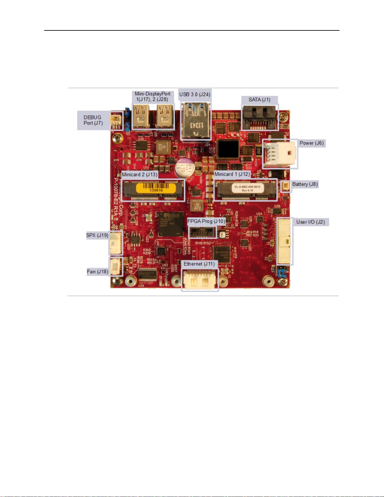
External Connectors ......................................................................................................... 17
Power Delivery ................................................................................................................. 18
Main Power Connector ........................................................................................ 18
Cabling ................................................................................................................. 19
Power Requirements ............................................................................................ 19
Power Delivery Considerations ........................................................................... 19
Power Button ....................................................................................................... 20
Supported Power States ....................................................................................... 20
Battery Power Options ......................................................................................... 21
External Speaker ............................................................................................................... 22
Push-button Reset ............................................................................................................. 22
CPU Fan Connector .......................................................................................................... 23
Cabling ................................................................................................................. 24
Mass Storage Interfaces ............................................................................................. 25
SATA Interface ................................................................................................................. 25
Multi-purpose I/O ......................................................................................................... 26
USB Interfaces .................................................................................................................. 26
Mini PCIe Sockets ............................................................................................................ 27
W_DISABLE# Signal .......................................................................................... 29
VL-EPU-4460 Reference Manual v
Page 6

Mini PCIe Card Wireless Status LEDs ................................................................ 30
SATA Activity LED ............................................................................................ 31
User I/O Connector ........................................................................................................... 32
Cabling ................................................................................................................. 33
SPX* Expansion Bus ........................................................................................................ 34
Cabling ................................................................................................................. 35
Serial I/O ...................................................................................................................... 36
Serial Ports ........................................................................................................................ 36
Serial Port Connector Pinout ............................................................................... 37
Cabling ................................................................................................................. 37
COM Port Configuration ..................................................................................... 37
Console Redirection ......................................................................................................... 37
Video Interfaces ........................................................................................................... 38
Mini DisplayPort++ Connectors ....................................................................................... 38
VGA Output......................................................................................................... 40
LVDS Interface ................................................................................................................. 41
LVDS Flat Panel Display Connectors ................................................................. 41
LVDS Backlight Connector ................................................................................. 44
Network Interfaces ...................................................................................................... 45
Ethernet Connector .............................................................................................. 45
Cabling ................................................................................................................. 46
Ethernet Status LED ............................................................................................ 47
VL-CBR-4005B Paddleboard ....................................................................................... 48
VL-CBR-4005B Connectors and Indicators ........................................................ 48
User I/O Connector .............................................................................................. 49
Cabling ................................................................................................................. 50
On-board Battery ................................................................................................. 50
Auxiliary I/O Connector ...................................................................................... 51
Dimensions and Mounting Holes ........................................................................ 52
Thermal Considerations ............................................................................................. 53
Selecting the Correct Thermal Solution for Your Application ........................................ 53
Heat Plate ............................................................................................................. 53
System-level Considerations ............................................................................... 53
CPU Thermal Trip Points .................................................................................... 54
Thermal Specifications, Restrictions, and Conditions ........................................ 55
Overall Restrictions and Conditions: ................................................................... 55
Heat Plate Only Restrictions and Conditions: ..................................................... 55
Heat Sink Only Considerations: .......................................................................... 55
Heat Sink with Fan Considerations: .................................................................... 56
EPU-4460 Thermal Characterization ............................................................................... 56
Test Results.......................................................................................................... 57
Installing VersaLogic Thermal Solutions ......................................................................... 59
Hardware Assembly ............................................................................................. 59
Installing the VL-HDW-416 Passive Heat Sink .................................................. 61
Installing the VL-HDW-415 Heat Sink Fan ........................................................ 63
vi VL-EPU-4460 Reference Manual
Page 7

Figures
Figure 1. T he Condor (V L-EPU-4460) ........................................................................................................... 9
Figure 2. Condor (VL-EPU-4460) Block Diagram ....................................................................................... 11
Figure 3. Condor Dimensions and Mounting Hole s ...................................................................................... 12
Figure 4. Jumpers As-Shipped Configuration................................................................................................ 15
Figure 5. Top Baseboard Connector Locations ............................................................................................. 17
Figure 6. Main Power Connector Pin Orientation ......................................................................................... 18
Figure 7. Location and Pin Orientation of the Battery Connector ................................................................. 21
Figure 8. VL-CBR-0203 Latching Battery Module ....................................................................................... 22
Figure 9. Location and Pin Orientation of the CPU Fan Connector .............................................................. 23
Figure 10. Location of the SATA Connector ................................................................................................ 25
Figure 11. Location of the USB Ports ........................................................................................................... 26
Figure 12. Location of Mini PCIe Sockets .................................................................................................... 27
Figure 13. Mini PCIe Wireless Status LEDs ................................................................................................. 30
Figure 14. Location of the SATA/mSATA Activity LED ............................................................................. 31
Figure 15. Location and Pin Orientation of the User I/O Connector ............................................................. 32
Figure 16. SPX Connector Location and Pin Configuration ......................................................................... 34
Figure 17. Location and Pin Orientation of the Serial I/O Connectors .......................................................... 36
Figure 18. Location of the Mini DisplayPort++ Connectors ......................................................................... 39
Figure 19. VL-CBR-2032 Mini DisplayPort to VGA Adapter ...................................................................... 40
Figure 20. Location of the LVDS Connectors ............................................................................................... 41
Figure 21. Lo cation and Pin Orientation of the Ethernet Connector ............................................................. 45
Figure 22. O nboard Ethernet Status LEDs .................................................................................................... 47
Figure 23. V L-CBR-4005B Connectors, Switches, and LEDs ...................................................................... 48
Figure 24. Location and Pin Orientation of the User I/O Connector ............................................................. 49
Figure 25. Location and Pin Orientation of Auxiliary I/O Connector ........................................................... 51
Figure 26. V L-CBR-4005B Dimensions and Mounting Holes ...................................................................... 52
Figure 27. E PU-4460-EAP Dual Core Temperature Relative to Ambient Temperature ............................... 57
Figure 28. E PU-4460-EBP Dual Core Temperature Relative to Ambient Temperature ............................... 58
Figure 29. E PU-4460-ECP Dual Core Temperature Relative to Ambient Temperature ............................... 59
Figure 30. Heat Plate Down .......................................................................................................................... 60
Figure 31. Example of Heat Plate Up with a Heat Sink ................................................................................ 61
Figure 32. Installing the Passive Heat Sink ................................................................................................... 62
Figure 33. Installing the Heat Sink Fan ......................................................................................................... 63
Tables
Table 1. Jumper Blo ck Configurations .......................................................................................................... 15
Table 2. Condor Memory Characteristics ...................................................................................................... 16
Table 3. Main Power Connector Pinout ........................................................................................................ 19
Table 4. Supported Power States ................................................................................................................... 20
Table 5. CPU Fan Connector Pinout ............................................................................................................. 23
Table 6. Mini PCIe Socket 1 / mSATA Socket Pinout .................................................................................. 28
Table 7. Mini PCIe Card Wireless Status LEDs ............................................................................................ 30
Table 8. User I/O Connector Pinout and Pin Orientation .............................................................................. 33
Table 9. SPX Connector Pinout .................................................................................................................... 35
Table 10 COM1/COM2 Connector Pinout .................................................................................................... 37
Table 11. Mini DisplayPort++ Co nnecto r Pinout .......................................................................................... 39
Table 12. LVDS Flat Panel Display Connector Pinout ................................................................................. 42
Table 13. LVDS Backlight Connector Pinout ............................................................................................... 44
VL-EPU-4460 Reference Manual vii
Page 8

Table 14. Ethernet Connector Pi nout ............................................................................................................ 46
Table 15. User I/O Connector Pinout ............................................................................................................ 49
Table 16. Auxiliary I/O Connector Pinout .................................................................................................... 51
Table 17. CPU Thermal Trip Points .............................................................................................................. 54
Table 18. Temperature Monitoring Programs ............................................................................................... 55
Table 19. Absolute Minimum and Maximum Air Temperatures ................................................................... 55
Table 20. EPU-4460 Ther mal Testing Setup................................................................................................. 56
viii VL-EPU-4460 Reference Manual
Page 9
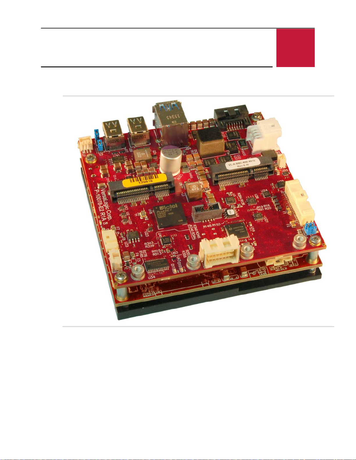
Figure 1. The Condor (VL-EPU-4460)
1
Introduction
Introduction
VL-EPU-4460 Reference Manual 9
Page 10

Introduction
Intel Core* i3-6100 (2.3 GHz, Dual
I2C support
Features
The Condor (VL-EPU-4460) is a feature-packed Embedded Processing Unit (EPU) engineered
and tested to meet the embedded industry’s evolving requirements to develop smaller, lighter,
and lower power embedded systems while adhering to stringent regulatory standards.
This embedded computer, equipped with an Intel Core
extreme temperature, impact, and vibration. Its features include:
Core), i5-6300 (2.4GHz, Dual Core),
or i7-6600 (2.6 GHz, Dual Core)
processor
Up to 32 GB DDR4 RAM
Two auto-detect 10BaseT/
100BaseTX/1000BaseT Ethernet
ports with network boot support
(Port 1 only)
Integrated Intel HD 520* Graphics
Gen 9 core supports DirectX* 12,
OpenGL 4.4, and H.264, MPEG-2
encoding/decoding. Dual Mini
DisplayPort and LVDS video
outputs. LVDS backlight control
Four USB 2.0 host ports, two
USB 3.0/2.0 port
Two RS-232/422/485 COM ports
Wide input voltage range (8 – 30V)
* 6xxx processor, is designed to withstand
Two Mini PCIe sockets
Full ACPI support
6 Gb/s SATA port support bootable
SATA hard drives
Watchdog Timer, prescaler of
approximately 1 μs to 10 minutes.
Standard heat plate with optional
thermal solutions
Field upgradeable AMI UEFI BIOS
with enhancements
RoHS compliant
Extended temperature operation
Customization available
Trusted Platform Module
Input under-voltage and over-voltage
protection
The Condor is compatible with popular operating systems including Microsoft Windows
and Linux (see the VersaLogic OS Compatibility Chart
Condor EPUs receive 100% functional testing and are backed by a limited five-year warranty.
Careful parts sourcing and US-based technical support ensure the highest possible quality,
reliability, service, and product longevity for this exceptional EPU.
).
*/WES7,
Technical Specifications
Refer to the Condor Data Sheet for complete specifications. Specifications are subject to change
without notification.
10 VL-EPU-4460 Reference Manual
Page 11
Block Diagram
USB 2.0 Port 6
SATAPort 0
LPC
InterfaceOn-Board
Key :
PCIe Port 0
CB_WDT
SLEEP#
Pwr Mgmt
(SLP_S3#, et al)
USB0
2.0
USB2
2.0
USB1
2.0
USB3
2.0
Minicard #2
(Full Size)
V12_COME (AB, CD)
V5SB
SATAConn
LPC Clock
Mag
PLED
Power Input
Power FAULT
Regulators, Power
Switches(5V, 3.3V,
1.5V)
FPGA
A3P400-FG144
(13x13FBGA)
Multifunction 3.3V GPIO (x8)
FAN_TACHIN
FAN_PWMOUT
PCIE_WAKE#
EPU-4460 (8-30V)
Wide-Range
Boost/Buck
Regulator
Clock
Fanout
(1:2)
ToTPM
Zero-delay
TPM
SPX
SPI SS0/1
XCVR
COM
CONN
FAN
CONN
On/Off/PWM
FANTACH
Dual LVDS (A,B)
(from via eDP)
PCIe Port 1
USB 2.0 Port 7
SMBus
Ethernet
USB 2.0 Port 2
USB 2.0 Port 3
USB 2.0 Port 4
USB 2.0 Port 5
USB_OC01#
USB_OC23#
USB_OC45#
USB_OC67#
SER0
BIO_DIS1#
I2C Bus
SPKR
VBATT
Debug Port
PCIe Ref Clk
Clock
Fanout
(1:3)
ToI210
ToMinic ard #1
ToMinic ard #2
Minicard #1
(Full Size)
DP++ (DP/HDMI)
mini-DP #2
1mm Hirose
USB VBUS
Power
Switches
LVDSBac klight
Pico-Clasp
Ethernet 0 GigE
MAC/PHY
Mag
2x8
Clik-Mate
Connector
E-Mux
I2043
FPGA Controls Mux
2:1 Emux
User I/O
On/Off
PB
Reset
PB
RST_BTN# PWR_BTN#
CBR-4005 Paddleboard
AUX
Connector
Batt
I2C
BATT
CONN
PCIe/SATA
PCIe
USB
SMBus
Ethernet Link/Status LEDs (x2)
USB0
USB1
USB2
USB3
PCIe Buffer
SUS_S3#
SUS_S4#
SUS_STAT#
THRMTRIP#
PWROK
PWR_BTN#
SYS_RST#
TYPE0#,TYPE1#,TYPE2# (CD)
DDI1 (CD)
DP++ (DP/HDMI)
mini-DP #1
USB 3.0 Ports 0,1 (CD)
USB 2.0 Ports 0,1
USB 3.0
DDI2 (CD)
PCIe Port 2
DDI3 (CD)
BIOS Flash
I2C-to-GPIO
I2C
Watchdog Reset
SMBus
(toFPGA also)
TVS, RF Filters,
OVP/UVP Circuit
Breaker
24Mhz
Not using TPM on COM
enables (4x)
(from FPGA)
Overcurrent Status
SATAPort 2
USB
NotAvailable on TC -170
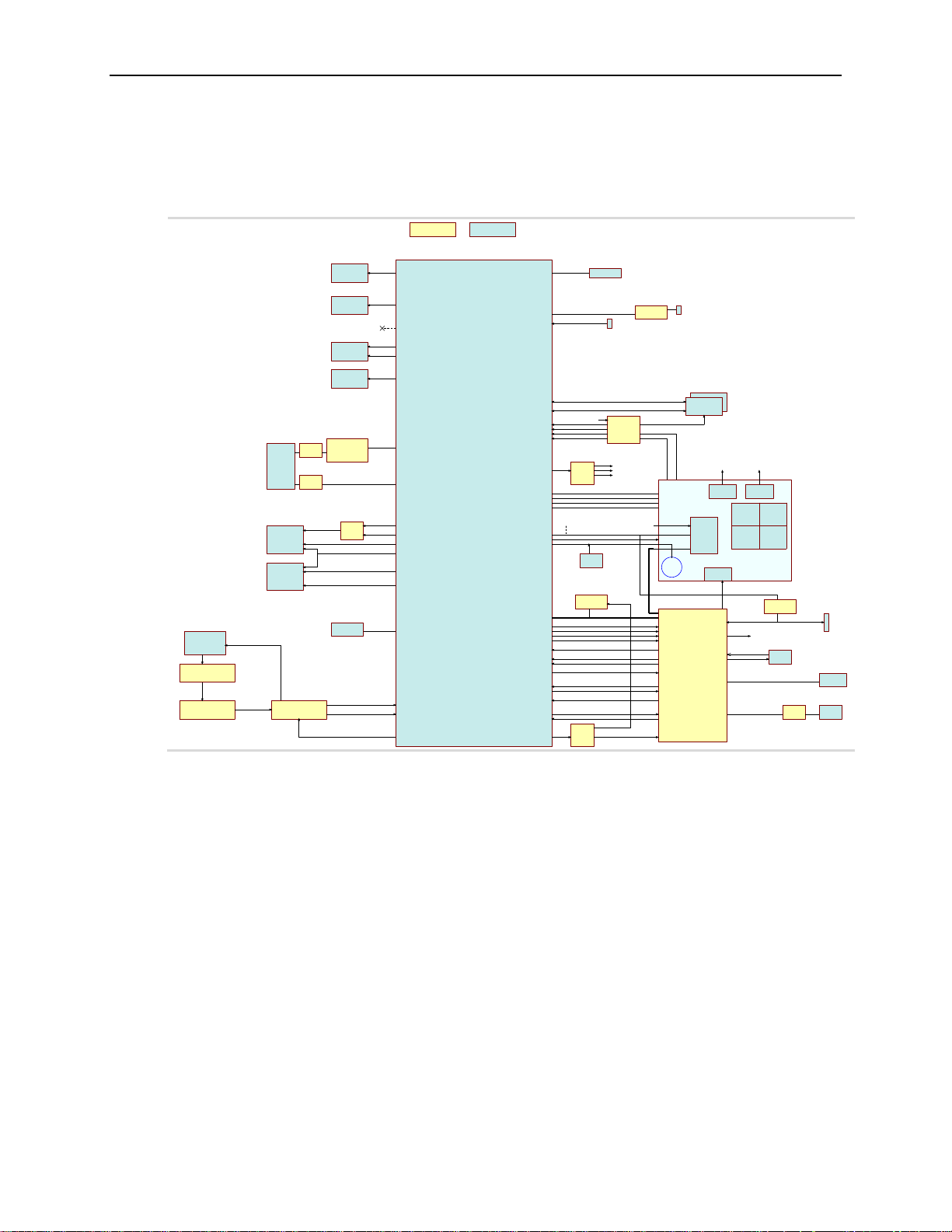
Figure 2. Condor (VL-EPU-4460) Block Diagram
Introduction
VL-EPU-4460 Reference Manual 11
Page 12
Introduction
Dimensions and Mounting
Condor Dimensions
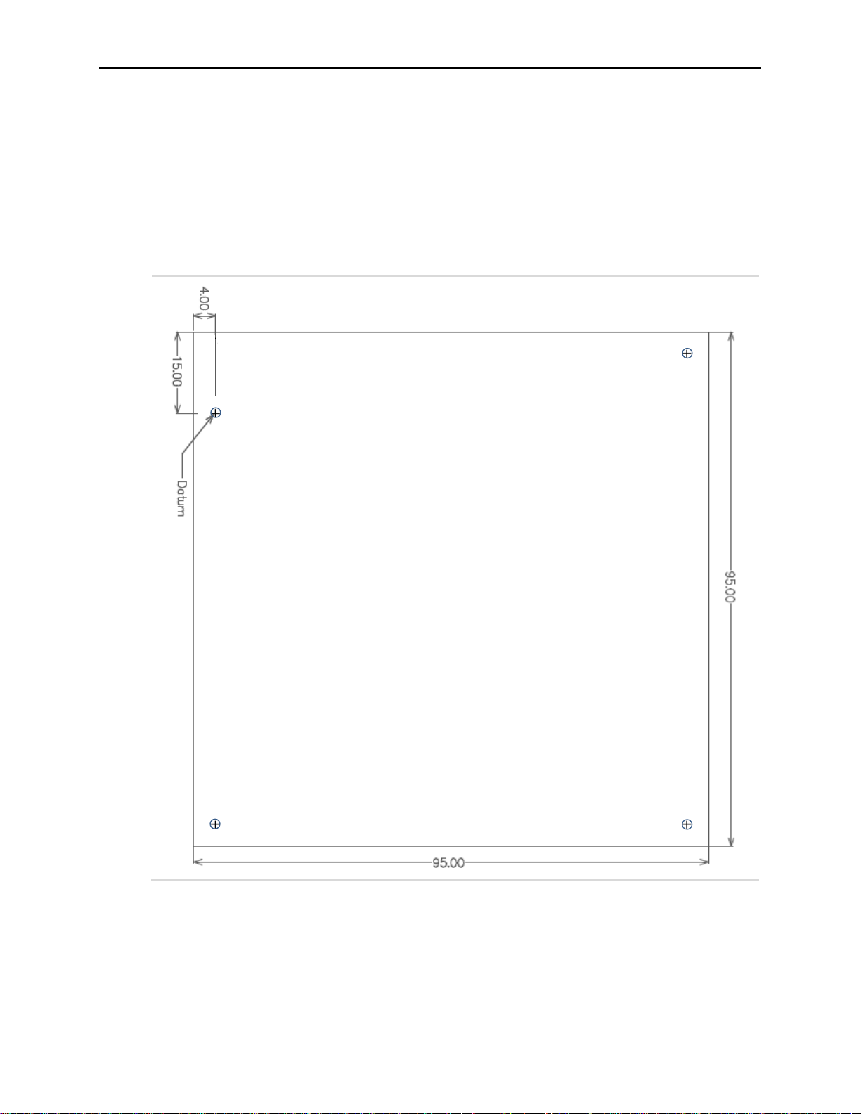
Figure 3. Condor Dimensions and Mounting Holes
(Not to scale. All dimensions in millimeters.)
12 VL-EPU-4460 Reference Manual
Page 13

Configuration and Setup
2
Initial Configuration
The following components are recommended for a typical development system with the Condor
EPU:
ATX power supply
VL-CBR-4005B paddleboard and VL-CBR-4005A cable. Refer to the chapter titled “VL-
CBR-4005B Paddleboard”, beginning on page 48 for details on the VL-CBR-4005B
paddleboard.
USB keyboard and mouse
SATA hard drive
USB CD-ROM drive
Configuration and Setup
VGA monitor and a VL-CBR-2032 Mini DisplayPort-to-VGA adapter
A thermal solution (using either VersaLogic accessories or a customer-designed solution)
You will also need an operating system (OS) installation CD-ROM.
Basic Setup
The following steps outline the procedure for setting up a typical development system. The
Condor should be handled at an ESD workstation or while wearing a grounded antistatic wrist
strap.
Before you begin, unpack the Condor and accessories. Verify that you received all the items you
ordered. Inspect the system visually for any damage that may have occurred in shipping. Contact
Gather all the peripheral devices you plan to attach to the Condor as well as their interface and
power cables. Attach standoffs to the board to stabilize it and make it easier to work with.
The next figure shows a typical setup for the Condor in the development environment.
1. Attach Cables and Peripherals
Attach a VGA monitor to the baseboard’s Mini DisplayPort++ connector using a VL-CBR-
2032.
Attach a SATA hard disk to the baseboard’s SATA connector using a VL-CBR-0702 cable.
immediately if any items are damaged or missing.
Attach a VL-CBR-4005B paddleboard to the baseboard’s User I/O connector.
Connect a USB keyboard and USB mouse to the USB Type-A connectors on the VL-CBR-
4005B paddleboard.
Attach a USB CD-ROM drive to one of the USB Type-A connectors on the VL-CBR-4005B
paddleboard.
13 VL-EPU-4460 Reference Manual
Page 14

Configuration and Setup
CAUTION: If BIOS default settings make the system unbootable and prevent the user
from entering the BIOS Setup utility, the Condor must be serviced by the factory.
2. Connect Power Source
Plug the power adapter cable VL-CBR-0809 into the main power connector on the
baseboard. Attach the motherboard connector of the ATX power supply to the adapter.
Attach an ATX power cable to any drive that is not already attached to the power supply
(hard drive or CD-ROM drive).
3. Install Thermal Solution
See the Installing Thermal Solutions section
3. Review Configuration
Before you power up the system, double-check all the connections. Make sure all cables are
oriented correctly, that adequate power is supplied to the Condor and all attached peripheral
devices.
4. Power On
Turn on the ATX power supply and the video monitor. If the system is correctly configured,
a video signal should be present.
5. Install Operating System
Install the operating system according to the instructions provided by the operating system
manufacturer.
BIOS Setup Utility
Refer to the VersaLogic System Utility Reference Manual for information on how to configure
the Condor BIOS.
The Condor permits you to store user-defined BIOS settings. This enables you to retrieve those
settings from cleared or corrupted CMOS RAM, or battery failure. All BIOS defaults can be
changed, except the time and date. BIOS defaults can be updated with the BIOS Update Utility.
Default BIOS Setup Values
After CMOS RAM clears, the system loads default BIOS parameters the next time the board
powers on. The default CMOS RAM setup values are used in order to boot the system whenever
the main CMOS RAM values are blank, or when the system battery is dead or has been removed
from the board.
Operating System Installation
The standard PC architecture used on the Condor makes the installation and use of most of the
standard x86-based operating systems very simple. The operating systems listed on the
VersaLogic Software Support
maker of the operating system. Special optimized hardware drivers for a particular operating
system, or a link to the drivers, are available on the
14 VL-EPU-4460 Reference Manual
page use the standard installation procedures provided by the
Condor Support Page.
Page 15
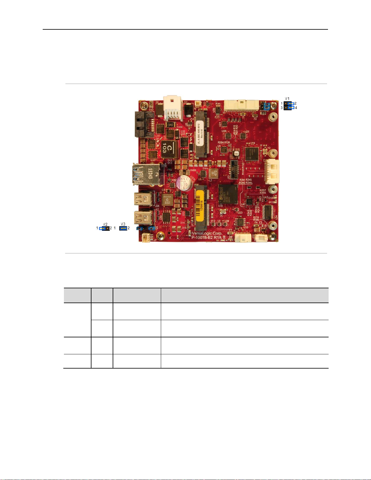
Jumper Blocks
Jumper
Jumper Out: Not terminated (RS-232) (default)
Jumper Out: Not terminated (RS-232) (default)
Jumper Out: Backup BIOS is not selected (default)
This jumper currently has no function. The jumper should be
left in the uninstalled position or removed.
Figure 4. Jumpers As-Shipped Configuration
Configuration and Setup
Jumper Configuration Summary
Table 1. Jumper Block Configurations
Block
V1
V2 1-2
V3 1-2
Pins Function Description
1-2
3-4
COM1 Endpoint
Termination
COM2 Endpoint
termination
Primary/Backup
BIOS Select
Reserved
Jumper In: Endpoint termination (for RS-485 or RS-422)
Jumper In: Endpoint termination (for RS-485 or RS-422)
Jumper In: Backup BIOS is selected
VL-EPU-4460 Reference Manual 15
Page 16
Board Features
Board Model
Memory Type
Capacity
Data Rate
3
CPU
The Intel Core 6xxx SoC features integrated 3D graphics, video encode and decode, and memory
and display controllers in one package. The following CPU configurations are available:
VL-EPU-4460-EAP: Intel Core 6100 – 2.3 GHz, Dual Core
VL-EPU-4460-EBP: Intel Core 6300 – 2.4 GHz, Dual Core
VL-EPU-4460-EDP: Intel Core 6600 – 2.6 GHz, Dual Core
CPU Die Temperature
The CPU die temperature is affected by numerous conditions, such as CPU utilization, CPU
speed, ambient air temperature, airflow, thermal effects of adjacent circuit boards, external heat
sources, and many others.
Board Features
The thermal management for the Intel 6xxx series of processors consists of a sensor located in
the core processor area. The processor contains multiple techniques to help better manage
thermal attributes of the processor. It implements thermal-based clock throttling and thermalbased speed step transitions. There is one thermal sensor on the processor that triggers Intel's
thermal monitor (the temperature at which the thermal sensor triggers the thermal monitor is set
during the fabrication of the processor). Triggering of this sensor is visible to software by means
of the thermal interrupt LVT entry in the local APIC. (See the
Datasheet for complete information.)
System RAM
The Condor has socketed SDRAM with the following characteristics:
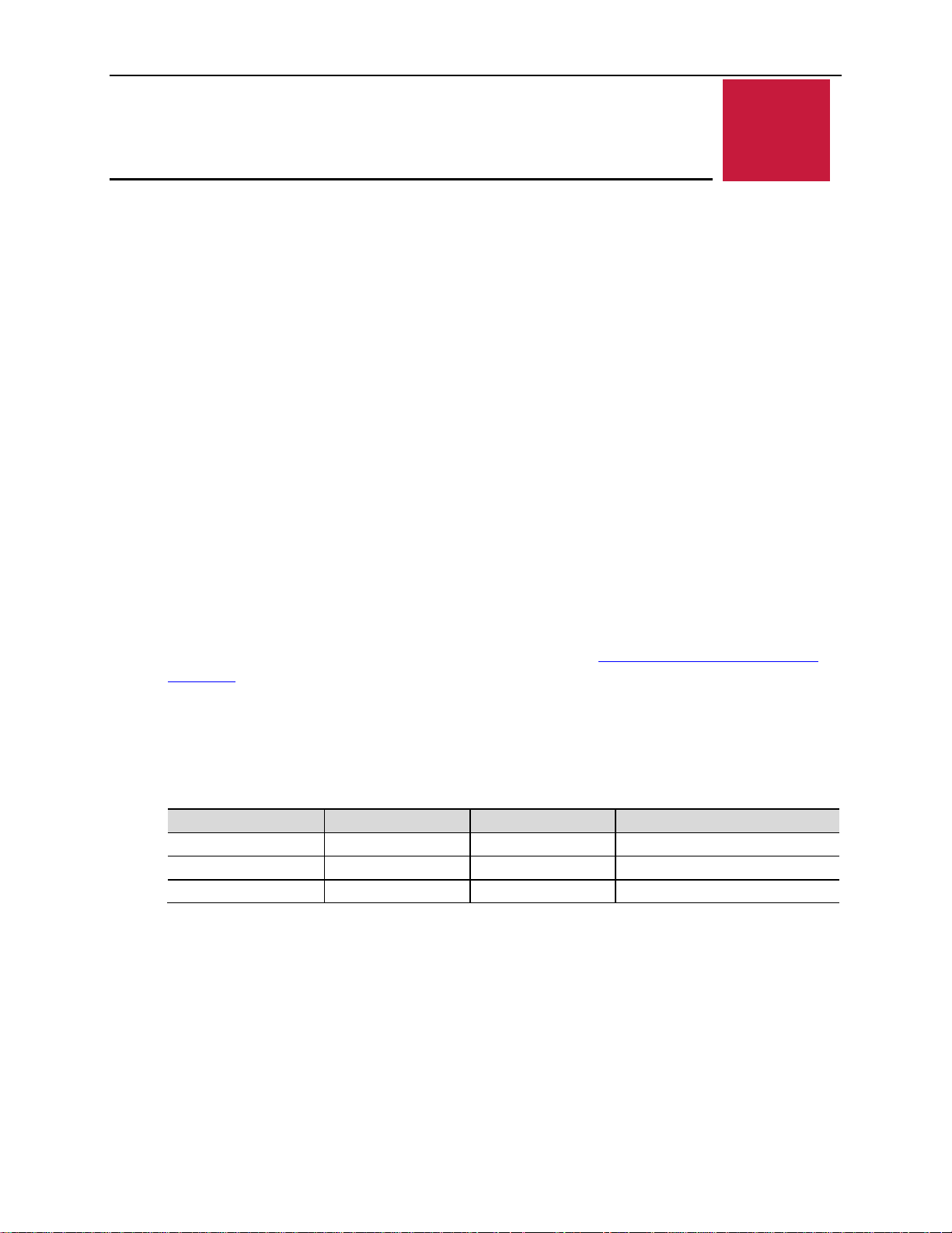
Table 2. Condor Memory Characteristics
VL-EPU-4460-EAP DDR4 8 GB 2133 MT/s – Dual Channel
VL-EPU-4460-EBP DDR4 16 GB 2133 MT/s – Dual Channel
VL-EPU-4460-ECP DDR4 16 GB 2133 MT/s – Dual Channel
Real-Time Clock (RTC)
The Condor features a real-time clock/calendar (RTC) circuit. The Condor supplies RTC voltage
in S5, S3, and S0 states, but requires an external +2.75 V to +3.3 V battery connection. Refer to
the section titled Battery Power Options on page 21 for more information. The BIOS Setup
utility sets the RTC.
Intel Core Processor U/Y Series
16 VL-EPU-4460 Reference Manual
Page 17
External Connectors
Figure 5. Top Baseboard Connector Locations
Board Features
VL-EPU-4460 Reference Manual 17
Page 18
Board Features
Power Delivery
Main Power Connector
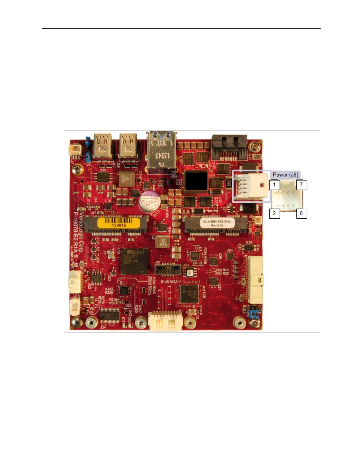
An 8-pin power connector applies the Main input power to the Condor. The next figure shows
the location and the pin orientation of the main power connector. Table 3 lists the pinout of the
main power connector.
Figure 6. Main Power Connector Pin Orientation
18 VL-EPU-4460 Reference Manual
Page 19
Table 3. Main Power Connector Pinout
Main input voltage
(+8V to +30V)
Main input voltage
(+8V to +30V)
Main input voltage
(+8V to +30V)
An open-drain signal
power fault (Note)
Note: A power fault can be due any of the following conditions:
The power input is under- or over-voltage (not in the 8 - 30V range)
Board Features
Pin Signal Description
1 PWRIN_POS
3 EARTH_GND Earth ground
5 POWER_FAULT
7 PWRIN_NEG Power return
• The input power is off
• The main input regulator has failed
•
• Low if power is OK
• Open if there is a
Pin Signal Description
2 PWRIN_POS
4 PWRIN_POS
6 PWRIN_NEG Power return
8 PWRIN_NEG Power return
Cabling
An adapter cable, part number VL-CBR-0809, is available for connecting the Condor to an ATX
power supply.
If your application requires a custom cable, the following information will be useful:
VL-EPU-4460 Board Connector Mating Connector
Molex 055959-0830 Molex 051353-0800
Power Requirements
The Condor requires a single +8 to +30 VDC supply capable of providing at least 35 W average
power that can also provide a peak power of 50 W. The input DC supply creates both the standby
and payload voltages provided to the CPU module.
The exact power requirements for the Condor depend on several factors, including CPU
configuration (the number of cores, CPU clock rate), memory configuration, peripheral
connections, and attached devices, and others. For example, driving long RS-232 lines at high
speed can increase power demand.
The VersaLogic VL-PS-ATX12-300A is a 1U size ATX power supply suitable for use with the
Condor. Use the VL-CBR-0809 adapter cable to attach the power supply to the main power
connector.
Power Delivery Considerations
Using the VersaLogic approved power supply (VL-PS-ATX12-300A) and power cable
(VL-CBR-0809) will ensure high quality power delivery to the board. Customers who design
their own power delivery methods should take into consideration the guidelines below to ensure
good power connections.
The specifications for typical operating current do not include any off-board power usage that
fed through the Condor power connector. Expansion boards and USB devices plugged into the
board will source additional power through the Condor power connector.
VL-EPU-4460 Reference Manual 19
Page 20
Board Features
All processor caches are flushed and the CPUs stop executing instructions. Power to
may be powered down.
Hibernation or Suspend-to-Disk. All content of main memory is saved to non-volatile
memory, such as a hard drive, and is powered down.
Soft Off. Almost the same as G3 Mechanical Off, except that the power supply still
A full reboot is
device.
Do not use wire smaller than 22 AWG. Use high quality UL 1007 compliant stranded wire.
The length of the wire should not exceed 18 inches.
Avoid using any additional connectors in the power delivery system.
The power and ground leads should be twisted together, or as close together as possible to
reduce lead inductance.
A separate conductor must be used for each of the power pins.
All power input pins and all ground pins must be independently connected between the
power source and the power connector.
Use a high quality power supply that can supply a stable voltage while reacting to widely
varying current draws.
Power Button
The User I/O connector (shown in Figure 15 on page 32) includes an input for a power button. A
momentary short to ground or assertion of pin 17 will cause a power button ACPI event. The
button event can be configured in Windows to enter an S3 power state (Sleep, Standby, or
Suspend-to-RAM), an S4 power state (Hibernate or Suspend-to-Disk), or an S5 power state
(Shutdown or Soft-Off). This connector uses IEC 61000-4-2-rated TVS components to help
protect against ESD damage.
A power button is provided on the VL-CBR-4005B paddleboard. Refer to the chapter titled VLCBR-4005B Paddleboard, beginning on page 48 for more information.
Supported Power States
This table lists the Condor’s supported power states.
Table 4. Supported Power States
Power state Description
S0 (G0) Working
S1 (G1-S1)
S3 (G1-S3) Commonly referred to as Standby, Sleep, or Suspend-to-RAM. RAM remains powered.
S4 (G1-S4)
S5 (G2)
G3 Mechanical off (ATX supply switch turned off).
the CPUs and RAM is maintained. Devices that do not indicate they must remain on
provides power, at a minimum, to the power button to allow return to S0.
required. No previous content is retained. Other components may remain powered so
the computer can "wake" on input from the keyboard, clock, modem, LAN, or USB
20 VL-EPU-4460 Reference Manual
Page 21
Board Features
Battery Power Options
The battery circuit on the Condor provides power for the Real-Time Clock (RTC) and power to
store BIOS Setup utility settings in non-volatile RAM.
The Condor has multiple options for providing battery power:
Use an external battery (the VL-CBR-0203, for example) connected to the board through the
battery connector.
Use the battery supplied with the CBR-4005B paddleboard
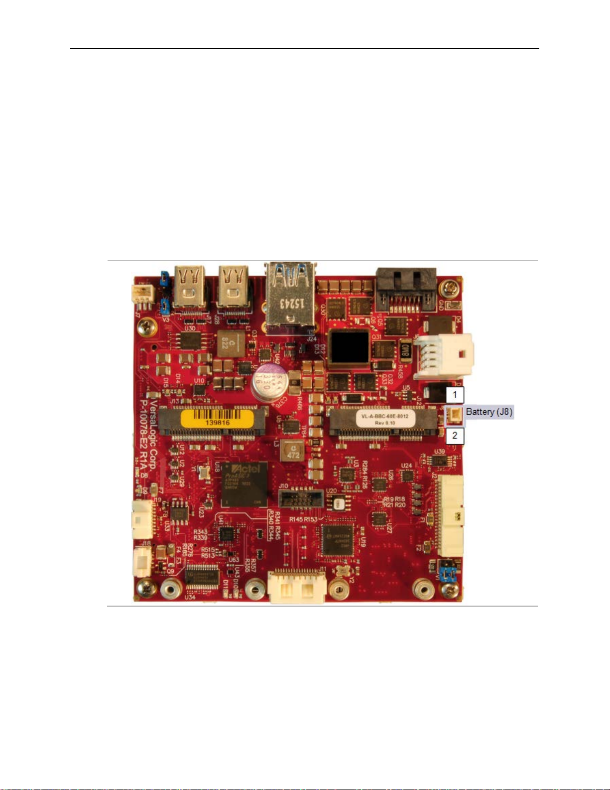
The figure below shows the location and pin orientation of the battery connector.
Figure 7. Location and Pin Orientation of the Battery Connector
VL-EPU-4460 Reference Manual 21
Page 22
Board Features
Cabling
If your application requires a custom cable, the following information will be useful:
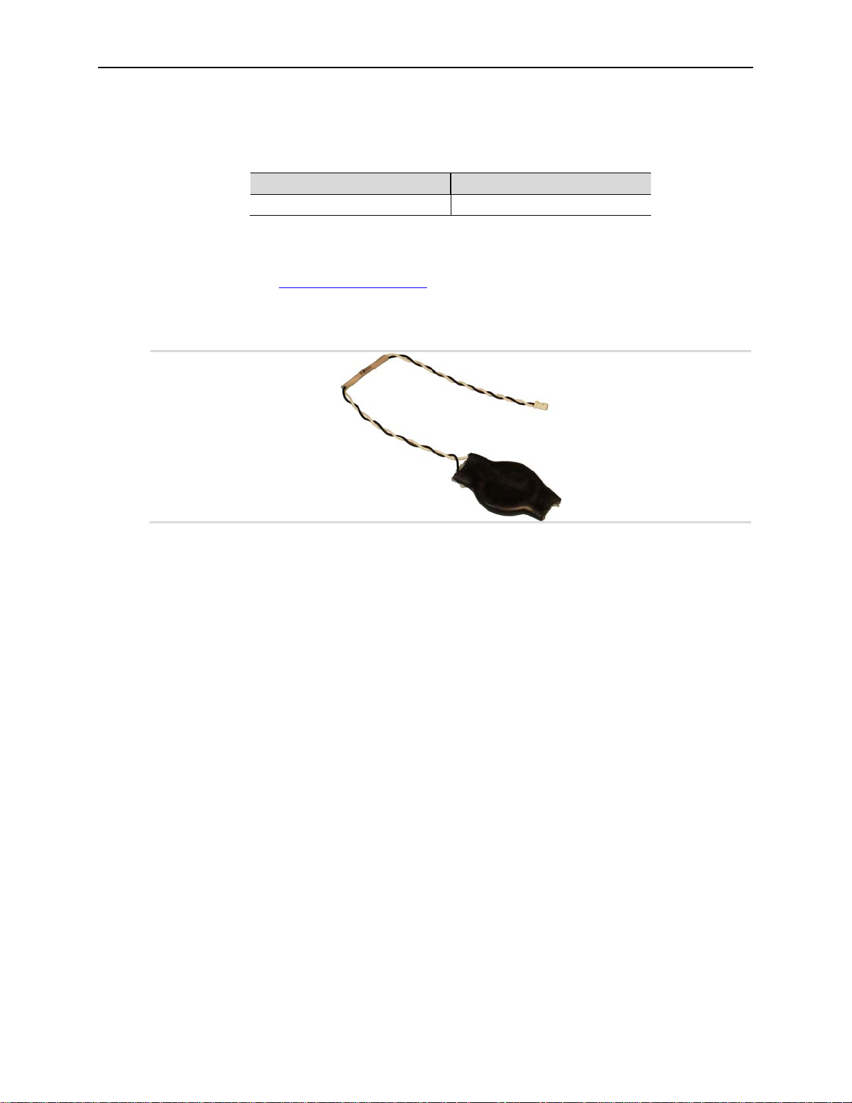
VL-CBR-0203 External Battery Module
The VL-CBR-0203 external battery module is compatible with the Condor. For more
information, contact [email protected]
Figure 8. VL-CBR-0203 Latching Battery Module
VL-EPU-4460 Board Connector Mating Connector
Molex 501331-0207 Molex 501330-0200
.
External Speaker
The User I/O connector (shown in Figure 15 on page 32) includes a speaker output signal at pin
15. The VL-CBR-4005B paddleboard provides a piezoelectric speaker. Figure 23 on page 48
shows the location of the piezoelectric speaker on the VL-CBR-4005B paddleboard.
Push-button Reset
The User I/O connector (shown in Figure 15 on page 32) includes an input for a push-button
reset switch. Shorting pin 18 to ground causes the Condor to reboot. This must be a mechanical
switch or an open-collector or open-drain active switch with less than a 0.5V low-level input
when the current is 1 mA. There must be no pull-up resistor on this signal. This connector uses
IEC 61000-4-2-rated TVS components to help protect against ESD damage.
A reset button on the VL-CBR-4005B paddleboard is provided. Refer to the chapter titled VLCBR-4005B Paddleboard, beginning on page 48 for more information.
22 VL-EPU-4460 Reference Manual
Page 23
CPU Fan Connector
Pin
Signal
1
Ground
2
+12 VDC
3
FAN_TACH
4
FAN_CONTROL
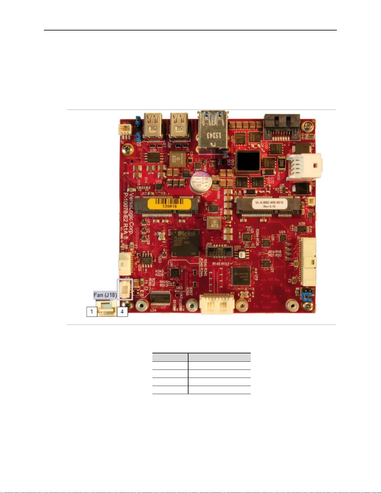
The Condor provides a four-pin CPU fan connector. The figure below shows the location and pin
orientation of the CPU fan connector.
Figure 9. Location and Pin Orientation of the CPU Fan Connector
Board Features
This table provides the pinout of the CPU fan connector.
Table 5. CPU Fan Connector Pinout
VL-EPU-4460 Reference Manual 23
Page 24

Board Features
Cabling
If your application requires a custom cable, the following information will be useful:
EPU-4460 Board Connector Mating Connector
Molex 502386-0470 Molex 502380-0400
24 VL-EPU-4460 Reference Manual
Page 25
SATA Interface
4
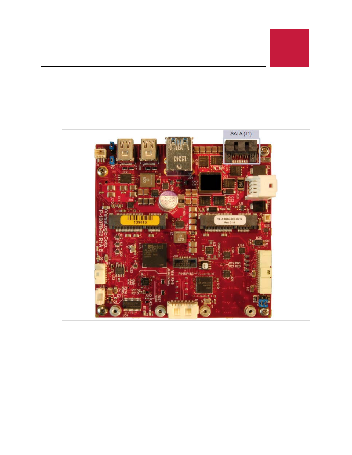
The Condor provides one serial ATA (SATA) port that communicates at a rate of up to
6.0 Gbits/s Both Standard (VL-CBR-0701) or Latching (VL-CBR-0702) cables are supported.
Figure 10. Location of the SATA Connector
Mass Storage Interfaces
Mass Storage Interfaces
VL-EPU-4460 Reference Manual 25
Page 26
Multi-purpose I/O
5
USB Interfaces
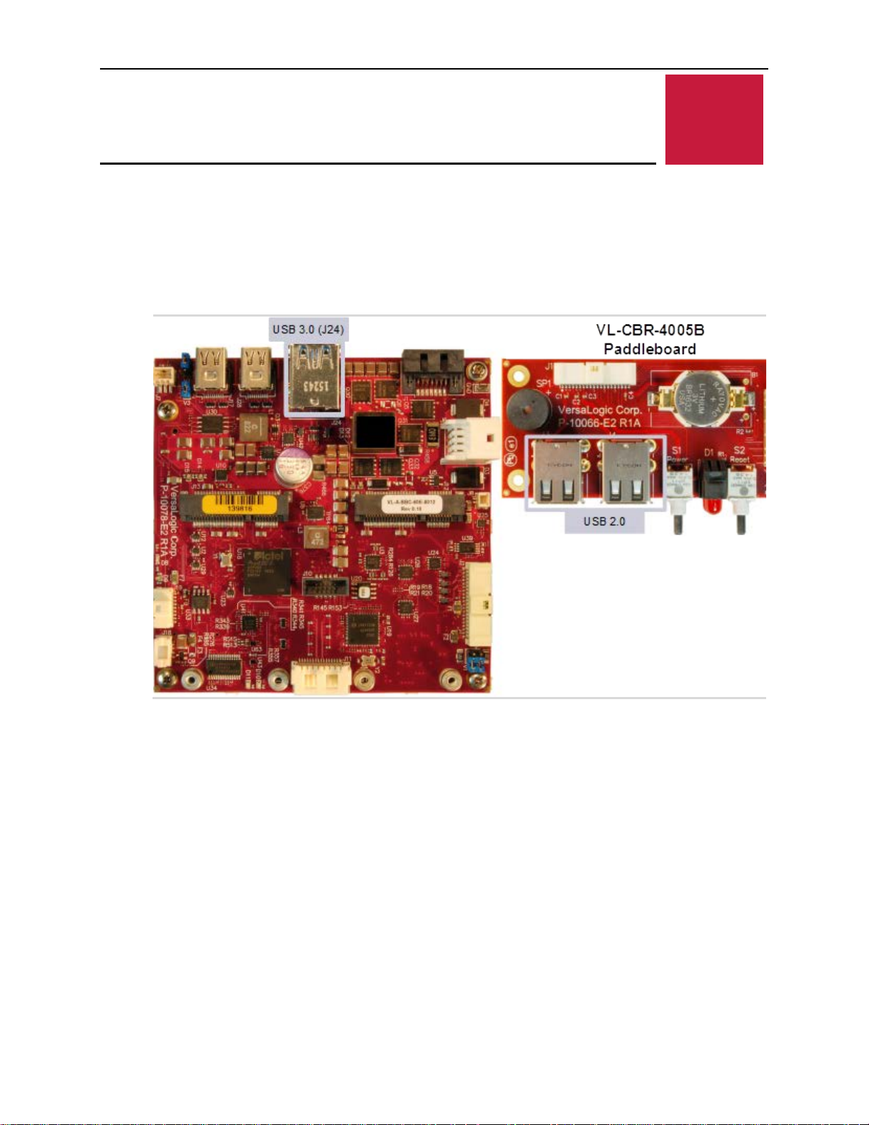
As shown below, the Condor supports four USB 2.0 Host ports and two USB 3.0 Super-Speed
ports.
Figure 11. Location of the USB Ports
Multi-purpose I/O
26 VL-EPU-4460 Reference Manual
Page 27
Mini PCIe Sockets
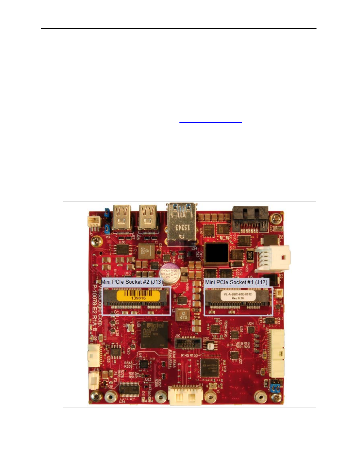
Mini PCIe Socket #1 supports the use of an mSATA card; Socket #2 does not.
The figure below shows the location of the two Mini PCIe sockets. Mini PCIe Socket #1 supports
the use of an mSATA card.
Each Mini PCIe interface includes one PCIe x1 lane, one USB 2.0 channel, and the SMBus
interface. The sockets are compatible with plug-in Wi-Fi modems, GPS receivers, MIL-STD1553, flash data storage, and other cards for added flexibility. For information on Mini PCIe
modules available from VersaLogic, contact [email protected]
The VL-MPEs-F1E series of mSATA modules provide flash storage of 4 GB, 16 GB, or 32 GB.
To secure a Mini PCIe card or mSATA module to the on-board standoffs, use two M2.5 x 6 mm
pan head Philips nylon screws. These screws are available in quantities of 10 in the VL-HDW108 hardware kit from VersaLogic.
Integrator’s Notes:
•
Multi-purpose I/O
.
Figure 12. Location of Mini PCIe Sockets
VL-EPU-4460 Reference Manual 27
Page 28
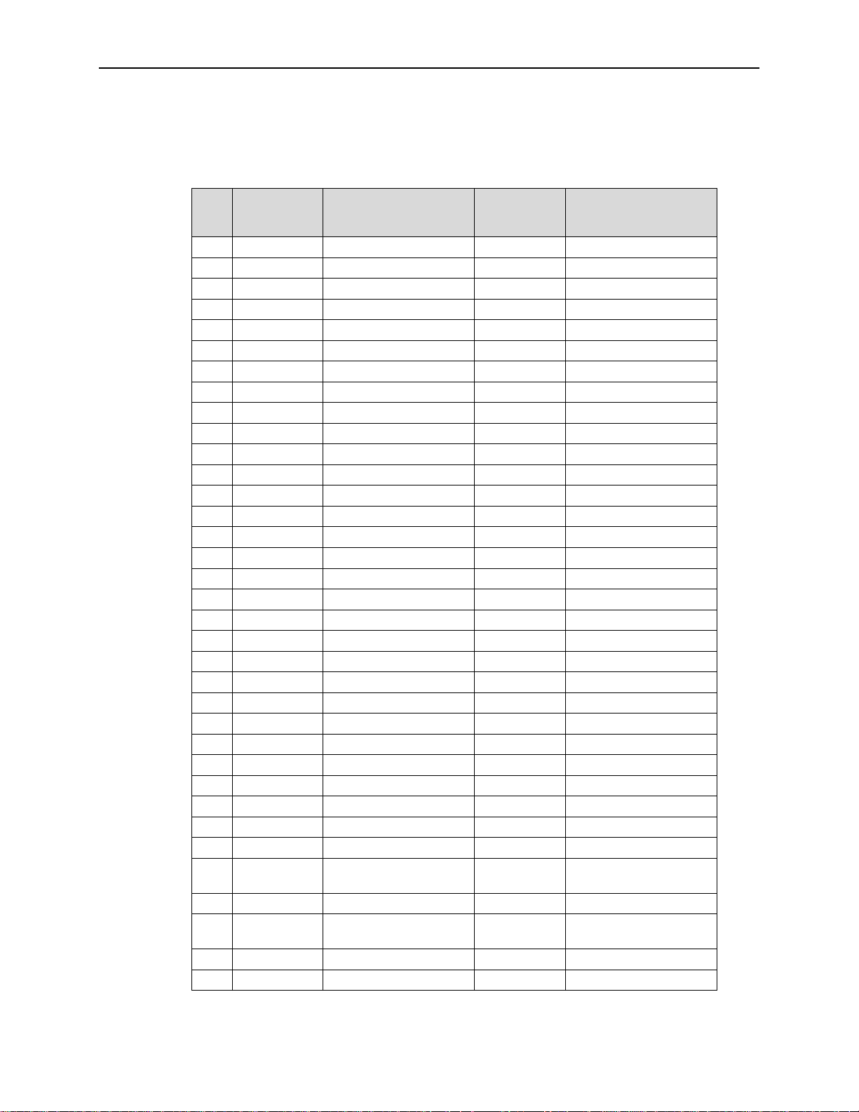
Multi-purpose I/O
mSATA
(minicard 2)
Table 6. Mini PCIe Socket 1 / mSATA Socket Pinout
Pin
10 NC Not connected Reserved Not connected
11 REFCLK- Reference clock input – Reserved Not connected
12 NC Not connected Reserved Not connected
13 REFCLK+ Reference clock input + Reserved Not connected
14 NC Not connected Reserved Not connected
15 GND Ground GND Ground
16 NC Not connected Reserved Not connected
17 NC Not connected Reserved Not connected
18 GND Ground GND Ground
19 NC Not connected Reserved Not connected
20 W_DISABLE# Wireless disable Reserved Not connected
21 GND Ground GND Ground
22 PERST# Card reset Reserved Not connected
23 PER0_N PCIe receive – SATA_RX_P Host receiver diff. pair +
24 3.3V 3.3 V +3.3V 3.3 V source
25 PER0_P PCIe receive + SATA_RX_N Host receiver diff. pair –
26 GND Ground GND Ground
27 GND Ground GND Ground
28 1.5V 1.5 V power +1.5V 1.5 V power
29 GND Ground GND Ground
30 SMB_CLK SMBus clock Two Wire I/F Two wire I/F clock
31 PET0_N PCIe transmit –
32 SMB_DATA SMBus data Two Wire I/F Two wire I/F data
33 PET0_P PCIe transmit +
34 GND Ground GND Ground
35 GND Ground GND Ground
Mini PCIe
Signal Name
1 WAKE# Wake Reserved Not connected
2 3.3V 3.3 V +3.3V 3.3 V source
3 NC Not connected Reserved Not connected
4 GND Ground GND Ground
5 NC Not connected Reserved Not connected
6 1.5V 1.5 V power +1.5V 1.5 V power
7 CLKREQ# Reference clock request Reserved Not connected
8 NC Not connected Reserved Not connected
9 GND Ground GND Ground
Mini PCIe Function
Signal Name
SATA_TX_N Host transmitter diff. pair
SATA_TX_P Host transmitter diff. pair
mSATA Function
(minicard 2)
–
+
28 VL-EPU-4460 Reference Manual
Page 29
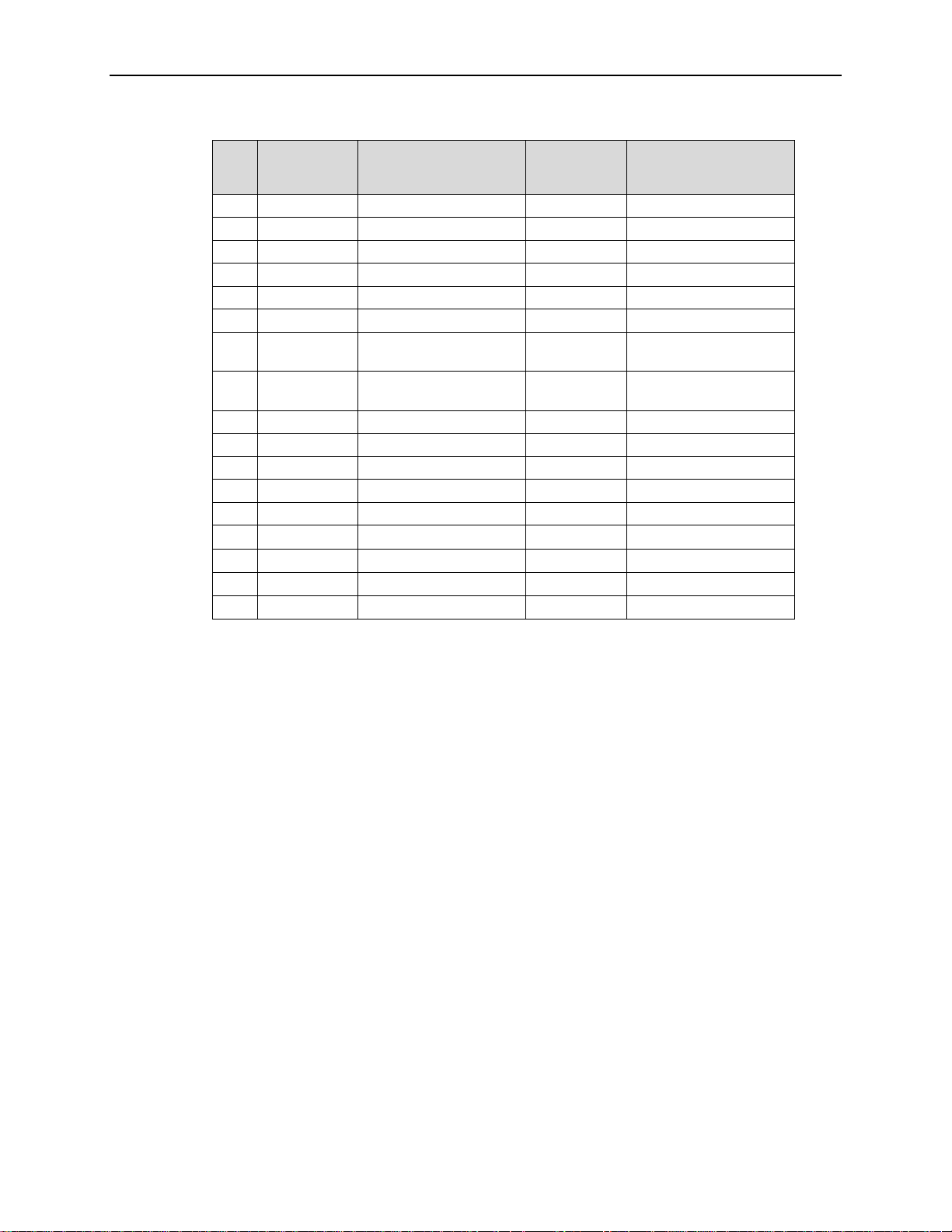
Multi-purpose I/O
mSATA
(minicard 2)
Note 2
Pin
36 USB_N USB data – Reserved Not connected
37 GND Ground GND Ground
38 USB_P USB data + Reserved Not connected
39 3.3V 3.3V +3.3V 3.3 V source
40 GND Ground GND Ground
41 3.3VAUX 3.3 V auxiliary source +3.3V 3.3 V source
42
43 GND mSATA Detec t (Note 1)
44 LED_WLAN# Wireless LAN LED Reserved Not connected
45 NC Not connected Vendor Not connected
46 LED_WPAN# Wireless PAN LED Reserved Not connected
47 NC Not connected Vendor Not connected
48 1.5V 1.5 V power +1.5V 1.5 V power
49 Reserved Reserved
50 GND Ground GND Ground
51 Reserved Reserved
52 3.3V 3.3 V +3.3V 3.3 V source
Mini PCIe
Signal Name
LED_WWAN
#
Mini PCIe Function
Wireless WAN LED
Signal Name
Reserved Not connected
GND/NC Ground/Not connected
DA/DSS
GND
mSATA Function
(minicard 2)
(
Device activity (Note 3)
Ground (Note 4)
)
Notes:
1. This pin is not grounded on the Condor on socket 1, since it can be used to detect the presence of
an mSATA module versus a Mini PCIe card.
2. This pin is not grounded on the Condor to make it available for mSATA module detection.
3. This signal drives the blue LED activity indicator shown in Figure 14. This LED lights with mSATA
disk activity (if supported by the mSATA module).
4. Some Mini PCIe cards use this signal as a second Mini PCIe card wireless disable input. On the
Condor, this signal is available for use for mSATA versus Mini PCIe card detection. There is an
option on the VersaLogic Features BIOS Setup utility screen for setting the mSATA detection
method.
W_DISABLE# Signal
The W_DISABLE# signal is for use with optional wireless Ethernet Mini PCIe cards. The signal
enables you to disable a wireless card’s radio operation in order to meet public safety regulations
or when otherwise desired. W_DISABLE# is an active low signal that when driven low (shorted
to ground) disables radio operation on the Mini PCIe card wireless device. When W_DISABLE#
is not asserted, or in a high impedance state, the radio may transmit if not disabled by other
means such as software. The W_DISABLE# signals for each of the two Minicards are controlled
by registers in the FPGA.
VL-EPU-4460 Reference Manual 29
Page 30
Multi-purpose I/O
Mini PCIe Card Wireless Status LEDs
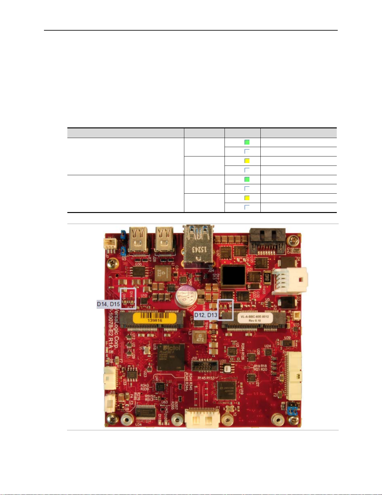
Dual-colored (green and yellow) LEDs provide status for modules installed in the Mini PCIe
sockets. These LEDs light when the associated device is installed and capable of transmitting.
The table below lists the states of the LEDs. The figure below shows the locations on the
Condor.
Table 7. Mini PCIe Card Wireless Status LEDs
D12 (minicard 1) and D14 (minicard 2)
D13 (minicard 1) and D15 (minicard 2)
LED Color State Description
Green
Yellow
Green
Yellow
On Wireless WAN active
Off Wireless WAN inactive
On
Wireless LAN active
Off Wireless LAN inactive
On Wireless PAN active
Off Wireless PAN inactive
On
Minicard power is ON
Off Minicard power is OFF
Figure 13. Mini PCIe Wireless Status LEDs
30 VL-EPU-4460 Reference Manual
Page 31
Multi-purpose I/O
SATA Activity LED
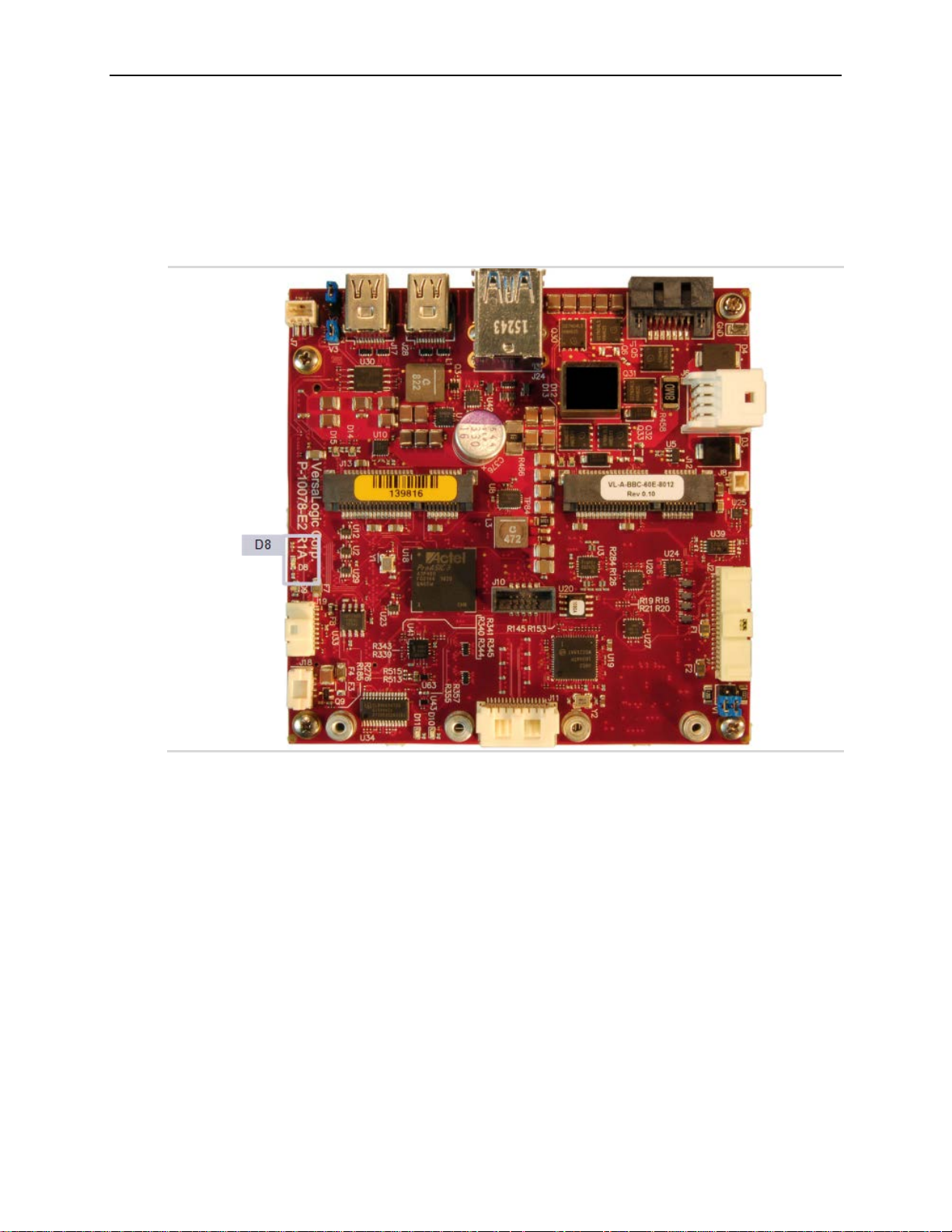
The figure below shows the location of the SATA/mSATA activity blue LED. This LED
indicates activity on either the SATA or the mSATA interface. Not all mSATA drives provide
this disk activity signal.
Figure 14. Location of the SATA/mSATA Activity LED
VL-EPU-4460 Reference Manual 31
Page 32
Multi-purpose I/O
User I/O Connector
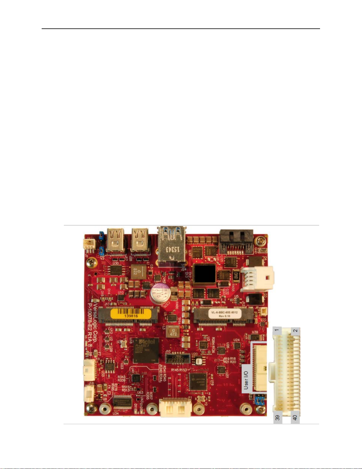
The 40-pin user I/O connector incorporates the signals for the following:
Four USB ports
Eight GPIO lines (these are functionally muxed with six timer I/O signals per FPGA
registers). There are eight timer signals and they share digital I/Os 16-9. The eight GPIO
lines on the paddleboard each have an alternate mode, accessible using the FPGA’s
AUXMOD1 register. Refer to the EPU-4460 Programmer’s Reference Manual for more
information on FPGA registers.
Three LEDs (two Ethernet link/status LEDs and a programmable LED)
Two I
Push-button power switch
Push-button reset switch
Speaker output
2
C signals (clock and data)
This connector uses IEC 61000-4-2-rated TVS components to help protect against ESD damage.
The figure below shows the location and pin orientation of the user I/O connector.
Figure 15. Location and Pin Orientation of the User I/O Connector
32 VL-EPU-4460 Reference Manual
Page 33
Pin
Signal
Pin
Signal
1
V5_USB1-2 (Note 1)
2
GND
3
USB1_P
4
USB2_P
5
USB1_N
6
USB2_N
7
V5_USB3-4 (Note 2)
8
GND
9
USB3_P
10
USB4_P
11
USB3_N
12
USB4_N
13
V3P3_S0 (Note 3)
14
GND
15
SPKR#
16
PLED#
17
PWR_BTN#
18
RST_BTN#
19
GND
20
GND
21
I2C_SCK
22
V_BATT
23
I2C_SDA
24
V_BATT Return
25
GND
26
GND
27
GPIO1
28
GPIO2
29
GPIO3
30
GPIO4
31
GND
32
GND
33
GPIO5
34
GPIO6
35
GPIO7
36
GPIO8
37
V3P3_SX (Note 4)
38
GND
39
ETH_LED1
40
ETH_LED2
Notes:
be powered by a 3.3 V power source.
The table below provides the pinout of the user I/O connector.
Table 8. User I/O Connector Pinout and Pin Orientation
Multi-purpose I/O
1. This is the +5V VBUS power for USB Port 1 and 2.
2. This is the +5V VBUS power for USB Port 3 and 4.
3. This 3.3 V power goes off in sleep modes. The SPKR# uses this power as
should the PLED# (there is no requirement for PLED# to use this power, but the
VL-CBR-4005B paddleboard does).
4. This 3.3 V power can be turned on or off similar to the 3.3V power to the Mini
Card via the FPGA (can go off in sleep modes or always stay on; by default it
goes off in sleep modes). It is used for the 10 kΩ pullup resistor power on the 8x
GPIOs and usually for the 2x Ethernet LEDs, however, the Ethernet LEDs can
Cabling
An adapter cable, part number VL-CBR-4005A, is available for connecting the CBR-4005B
paddleboard to the VL-EPU-4460. This is a 12-inch, Pico-Clasp 40-pin to 40-pin cable.
If your application requires a custom cable, the following information will be useful:
EPU-4460 Board Connector Mating Connector
Molex 501571-4007 Molex 501189-4010
VL-EPU-4460 Reference Manual 33
Page 34
Multi-purpose I/O
SPX* Expansion Bus
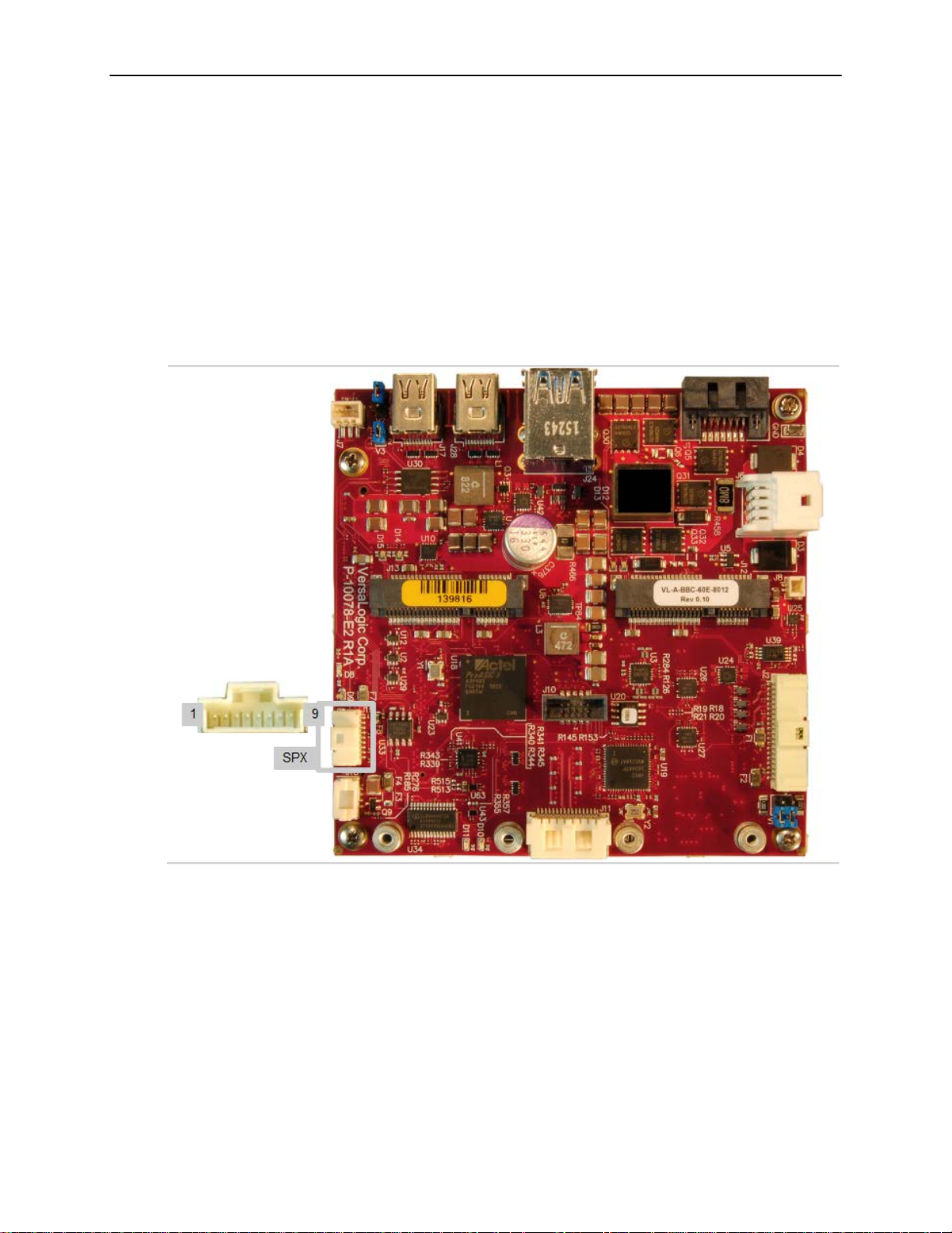
Up to two serial peripheral expansion (SPX) devices can be attached to the Condor at connector
using a CBR-0901 cable. The SPX interface provides the standard serial peripheral interface
(SPI) signals: CLK, MISO, and MOSI, as well as two chip selects, SS0# and SS1#. The +5 V
power provided to pin 1 of the SPX connector is protected by a 1 A resettable fuse.
The figure below shows the location and pin orientation of the SPX connector.
Figure 16. SPX Connector Location and Pin Configuration
34 VL-EPU-4460 Reference Manual
Page 35
Multi-purpose I/O
The table below lists the pinout of the SPX connector.
Table 9. SPX Connector Pinout
Pin Signal Function
1 VCC +5.0 V
2 SCLK SPX Clock
3 GND Ground
4 MISO Master input, Slave output
5 GND Ground
6 MOSI Master output, Slave input
7 GND Ground
8 SS0# Chip Select 0
9 SS1# Chip Select 1
SPI is, in its simplest form, a three wire serial bus. One signal is a clock, driven only by the
permanent master device on-board. The others are Data In and Data Out with respect to the
master. The SPX implementation on the Condor supports chip selects. The master device
initiates all SPI transactions. A slave device responds when its chip select is asserted and it
receives clock pulses from the master. All four common SPI modes are supported through the use
of clock polarity and clock idle state controls.
The SPI clock is derived from a 24 MHz PCI clock and can be software-configured to operate at
the following frequencies:
6 MHz (24 MHz/4)
3 MHz (24MHz/8)
1.5 MHz (24MHz/16)
0.75 MHz (24MHz/32)
Cabling
An adapter cable, part number CBR-0901, is available. This is a 9-inch, 9-pin Pico-Clasp to Dual
SPX cable.
If your application requires a custom cable, the following information will be useful:
EPU-4460 Board Connector Mating Connector
Molex 501568-0907 Molex 501330-0900
VL-EPU-4460 Reference Manual 35
Page 36
Serial I/O
6
Serial Ports
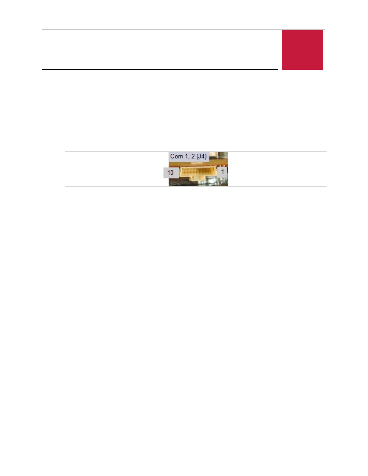
The Condor provides two serial ports. Both ports can be operated in RS-232, RS-422, or RS-485
mode. IRQ lines are chosen in the BIOS Setup utility. The UARTs are 16550-based serial ports
and are implemented in the FPGA.
The next figure shows the location and pin orientation of the two serial I/O connectors.
Figure 17. Location and Pin Orientation of the Serial I/O Connectors
Serial I/O
36 VL-EPU-4460 Reference Manual
Page 37
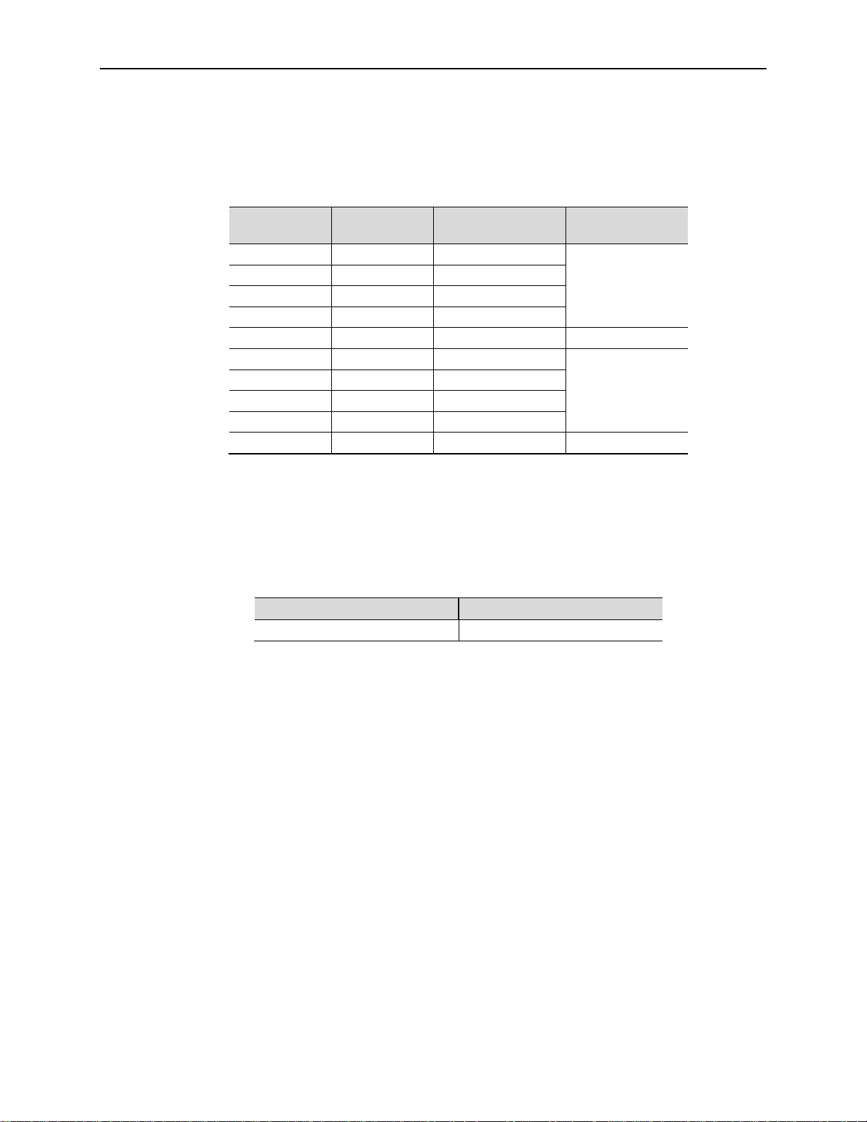
Serial Port Connector Pinout
Table 10 COM1/COM2 Connector Pinout
Serial I/O
Pin
1 RTS1 TXD1_P
2 TXD1# TXD1_N
3 CTS1 RXD1_P
4 RXD1# RXD1_N
5 GND GND —
6 RTS2 TXD2_P
7 TXD2# TXD2_N
8 CTS2 RXD2_P
9 RXD2# RXD2_N
10 GND GND —
RS-232 Signal RS-422/RS-485
Signal
Port
COM1
COM2
Cabling
An adapter cable, part number CBR-1014, is available for routing the serial I/O signals to 9-pin
D-sub connectors. This is a 12-inch, Pico-Clasp 10-pin to two 9-pin D-sub connector cable.
If your application requires a custom cable, the following information will be useful:
EPU-4460 Board Connector Mating Connector
Molex 501331-1007 Molex 501330-1000
COM Port Configuration
Jumper block V1 configures the serial ports for RS-485/RS-422 operation. See the section titled
“Jumper Blocks” on page 15 for details. The termination resistor should only be enabled for RS485 or RS-422 endpoint stations and not for intermediate stations. Termination must not be used
for RS-232.
Console Redirection
The Condor can be configured for remote access by redirecting the console to a serial
communications port. The BIOS Setup utility and some operating systems (such as MS-DOS)
can use this console for user interaction. The default settings for the redirected console are as
follows:
115,200 baud rate
8 data bits, No parity, 1 stop bit (that is, 8-None-1)
No flow control
VL-EPU-4460 Reference Manual 37
Page 38

Video Interfaces
7
The Intel Core* 6xxx processor series contains an integrated graphics engine with advanced
2D/3D graphics, video decode and encode capabilities, and a display controller. The Condor
provides the following video interfaces:
Two Mini DisplayPort++ connectors
Dual LVDS display connectors; a 4-pin LVDS backlight connector is also provided
Mini DisplayPort++ Connectors
DisplayPort consists of three interfaces:
Main Link – transfers high-speed isochronous video and audio data
Auxiliary channel – used for link management and device control; the EDID is read over this
interface
Video Interfaces
Hot Plug Detect – indicates that a cable is plugged in
The DisplayPort interface supports:
Audio signaling
DP++ mode allowing connection to an HDMI device through a passive adapter. “Passive”
means and it does not require software drivers or do protocol conversion.
The next figure shows the location of the 20-pin Mini DisplayPort++connector. Table 11 lists the
pinout of the Mini DisplayPort++ connector.
38 VL-EPU-4460 Reference Manual
Page 39
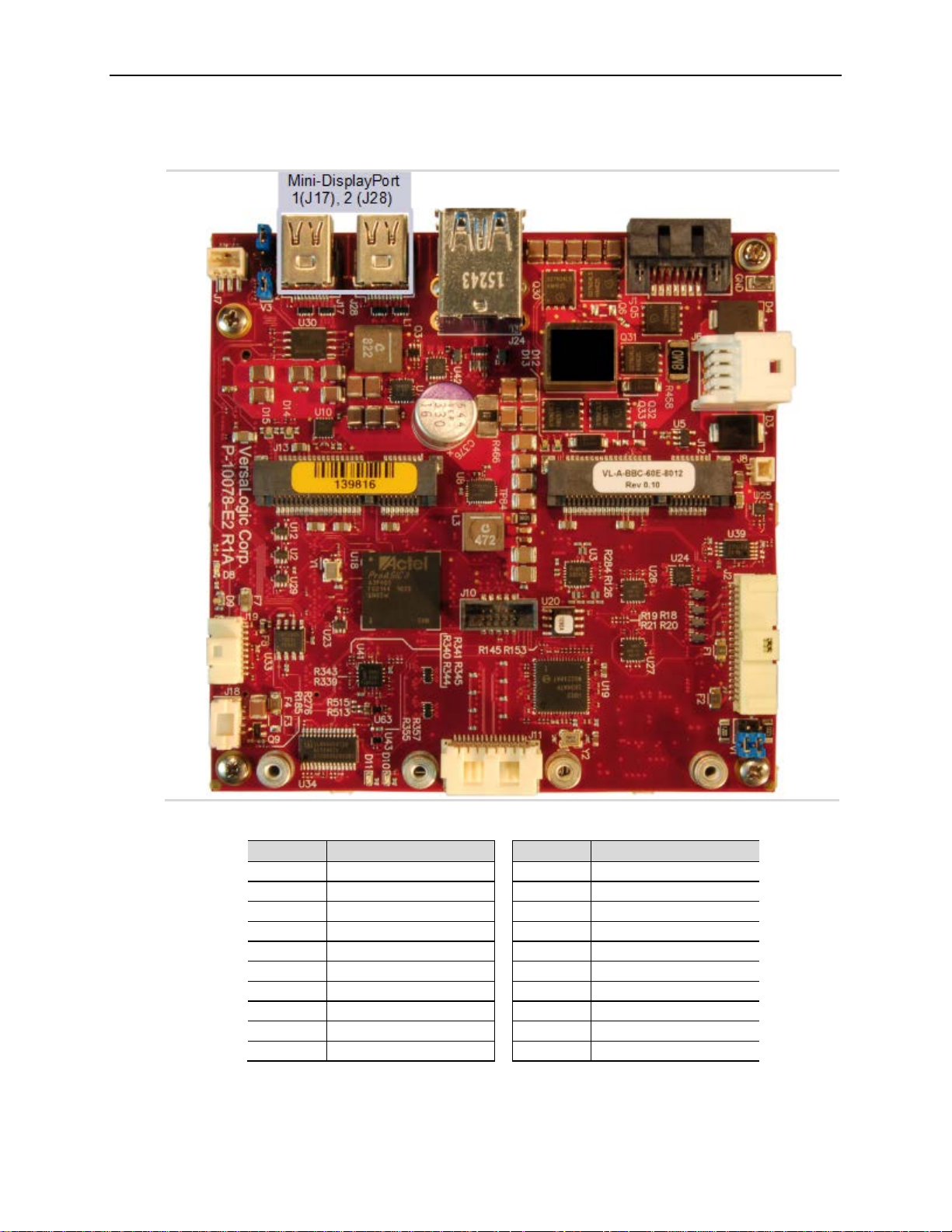
Figure 18. Location of the Mini DisplayPort++ Connectors
Pin
Signal
Pin
Signal
1
GND 2
HOT PLUG DETECT
3
ML_LANE0_P
4 CONFIG 1
5
ML_LANE0_N
6 CONFIG 2
7
GND 8
GND
9
ML_LANE1_P
10
ML_LANE3_P
11
ML_LANE1_N
12
ML_LANE3_N
13
GND 14
GND
15
ML_LANE2_P
16
AUX_CH_P
17
ML_LANE2_N
18
AUX_CH_N
19
GND 20
DP_POWER (3.3V)
Video Interfaces
VL-EPU-4460 Reference Manual 39
Table 11. Mini DisplayPort++ Connector Pinout
Page 40
Video Interfaces
VGA Output
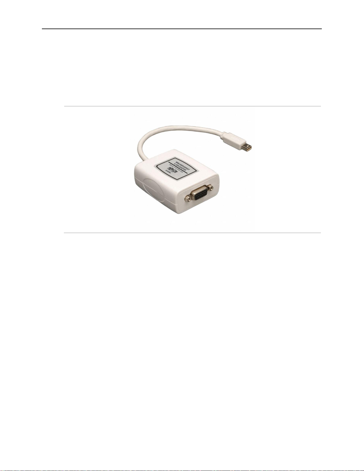
A VGA monitor can be attached to the Mini DisplayPort++ connector using the VL-CBR-2032
Mini DisplayPort-to-VGA adapter, similar to the one shown in the following figure.
Figure 19. VL-CBR-2032 Mini DisplayPort to VGA Adapter
40 VL-EPU-4460 Reference Manual
Page 41
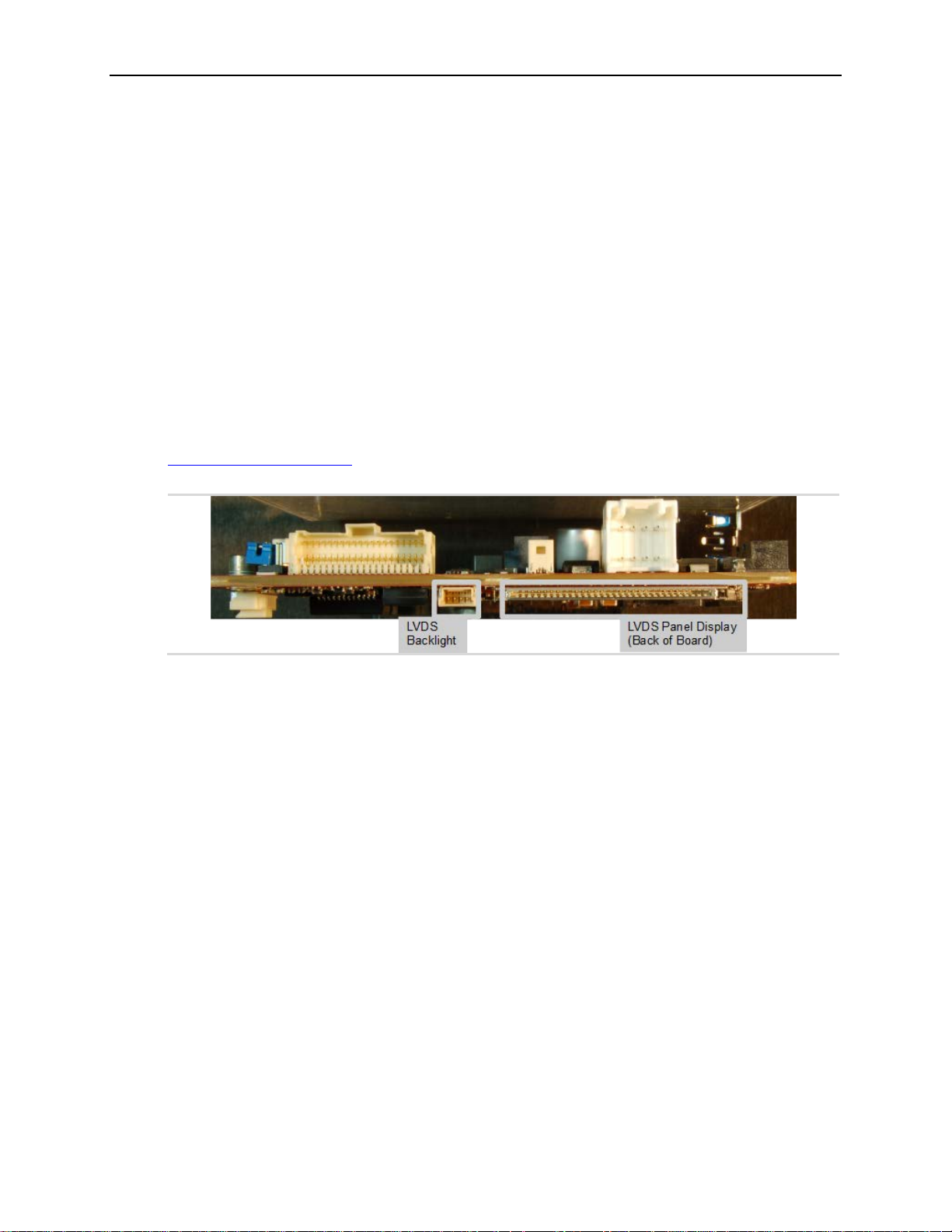
LVDS Interface
LVDS Flat Panel Display Connectors
The condor supports a full 24-bit Dual-LVDS panel interface. A 30-pin right-angle top-mount
connector VL P/N XPM1R30ST1 is used for this. 3.3V panel power is also supported and can
be switched on using the COM Module LVDS_VDDEN signal. Overcurrent status on this switch
can be read via the FPGA.
A COM Module supports LVDS backlight. The backlight enable and backlight control signals
are connected to a 4-pin pico-clasp connector VL P/N X1S1R04SL
The BIOS Setup utility provides several options for standard LVDS flat panel types. If these
options do not match the requirements of the panel you are using, contact
Figure 20. Location of the LVDS Connectors
Video Interfaces
for a custom video BIOS.
VL-EPU-4460 Reference Manual 41
Page 42
Video Interfaces
22
23
24
26
27
28
31
32
Table 12. LVDS Flat Panel Display Connector Pinout
Pin Signal Name Function
1 GD1 Guard (tie to Earth Ground).
2 LVDS_ODD0_N LVDS Odd Lane 0 Neg Diff Signal
3 LVDS_ODD0_P LVDS Odd Lane 0 Pos Diff Signal
4 LVDS_ODD1_N LVDS Odd Lane 1 Neg Diff Signal
5 LVDS_ODD1_P LVDS Odd Lane 1 Pos Diff Signal
6 LVDS_ODD2_N LVDS Odd Lane 2 Neg Diff Signal
7 LVDS_ODD2_P LVDS Odd Lane 2 Pos Diff Signal
8 GND1 Signal/Power Ground
9 LVDS_ODDCLK_N LVDS Odd Clock Neg Diff Signal
10 LVDS_ODDCLK_P LVDS Odd Clock Pos Diff Signal
11 LVDS_ODD3_N LVDS Odd Lane 3 Neg Diff Signal
12 LVDS_ODD3_P LVDS Odd Lane 3 Pos Diff Signal
13 LVDS_EVEN0_N LVDS Even Lane 0 Neg Diff Signal
14 LVDS_EVEN0_P LVDS Even Lane 0 Pos Diff Signal
15 GND2 Signal/Power Ground
16 LVDS_EVEN1_N LVDS Even Lane 1 Neg Diff Signal
17 LVDS_EVEN1_P LVDS Even Lane 1 Pos Diff Signal
18 GND3 Signal/Power Ground
19 LVDS_EVEN2_N LVDS Even Lane 2 Neg Diff Signal
20 LVDS_EVEN2_P LVDS Even Lane 2 Pos Diff Signal
21
25
29
30
LVDS_EVENCLK_N LVDS Even Clock Neg Diff Signal
LVDS_EVENCLK_P LVDS Even Clock Pos Diff Signal
LVDS_EVEN3_N LVDS Even Lane 3 Neg Diff Signal
LVDS_EVEN3_P LVDS Even Lane 3 Pos Diff Signal
GND4 Signal/Power Ground
GND5 Signal/Power Ground
VCC1 Panel Power (3.3V)
GND6 Signal/Power Ground
VCC2 Panel Power (3.3V)
VCC3 Panel Power (3.3V)
VCC4 Panel Power (3.3V)
GD2 Guard (tie to Earth Ground).
Cabling
The following LVDS cables are available for use with the Condor board:
VL-CBR-3001 – a 20-inch 2-Ch LVDS 30-pin JAE to 30-pin JAE
VL-CBR-3002 – a 20-inch 1-Ch LVDS 30-pin JAE to 1.25mm 20-pin Hirose
VL-CBR-3003 – a 20-inch 1-Ch LVDS 30-pin JAE to 20-pin JAE
If your application requires a custom cable, the following information will be useful:
42 VL-EPU-4460 Reference Manual
Page 43
EPU-4460 Board Connector Mating Connector
Hirose DF19G-20P-1H(54)
• Hirose DF19G-20S-1C (housing)
• Hirose DF19-2830SCFA x19 (crimp socket)
Video Interfaces
VL-EPU-4460 Reference Manual 43
Page 44
Video Interfaces
level signal by default
at higher voltages if the LVDS_BKLT_PWR is
level signal by default
but will operate at higher voltages if the LVDS_BKLT_PWR is
On-board +5V power is used when this is not connected.
LVDS Backlight Connector
Figure 20 on page 41 shows the location and pin orientation of the LVDS back light connector.
The next table lists the pinout of the LVDS backlight connector.
Table 13. LVDS Backlight Connector Pinout
Pin Signal Name Function
LVDS backlight enable output. (5V TTLbut will operate
1 LVDS_BKLT_EN
2 Signal Ground Ground
3 LVDS_BKLT_CTRL
4 LVDS_BKLT_LOGIC_PWR
provided).
High = enabled, Low = disabled.
LVDS backlight control output. (5V TTLprovided). This is a PWM signal and the duty cycle can be
set in the BIOS Setup utility.
Optional backlight logic power input. (Can range from +5V to
+14V and sets the high-value on the LVDS_BKLT_EN and
LVDS_BKLT_CTRL signals.)
Cabling
An adapter cable, part number CBR-0404, is available for powering the LVDS backlight from
the Condor board.
If your application requires a custom cable, the following information will be useful:
EPU-4460 Board Connector Mating Connector
Molex 501568-0407 Molex 501330-0400
44 VL-EPU-4460 Reference Manual
Page 45
Network Interfaces
8
Network Interfaces
The Condor provides two Gigabit Ethernet controllers (Intel I210-IT and Intel I219-LM). The
controllers provide a standard IEEE 802.3 Ethernet interface for 1000Base-T, 100Base-TX, and
10Base-T applications. The I210-IT Ethernet controller auto-negotiates connection speed.
Drivers are readily available to support a variety of operating systems. For more information on
this device, refer to the Intel I210 Ethernet Controller datasheet
Integrator’s Note: Ethernet Port 1 supports network boot; Port 0 does not.
Ethernet Connector
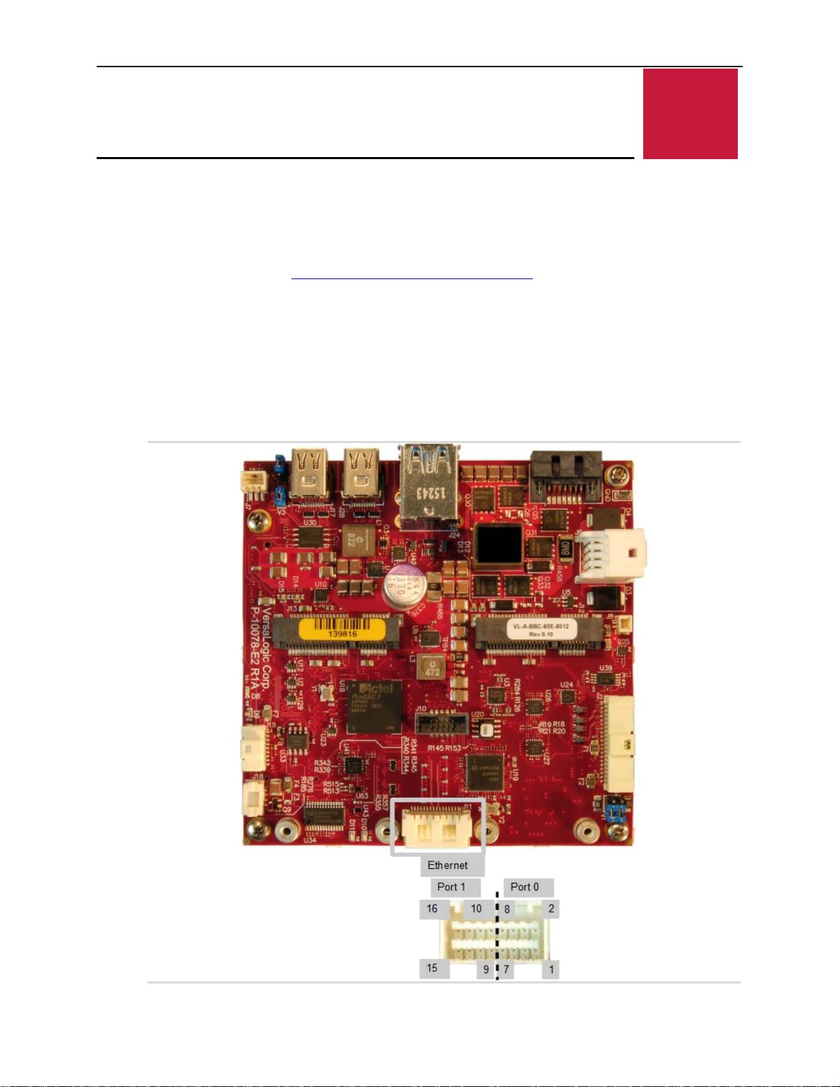
The Ethernet connector provides access to the Ethernet ports 0 and 1. The connector uses IEC
61000-4-2-rated TVS components to help protect against ESD damage. The figure below shows
the location and pin orientation of the Ethernet connector.
Figure 21. Location and Pin Orientation of the Ethernet Connector
.
VL-EPU-4460 Reference Manual 45
Page 46
Network Interfaces
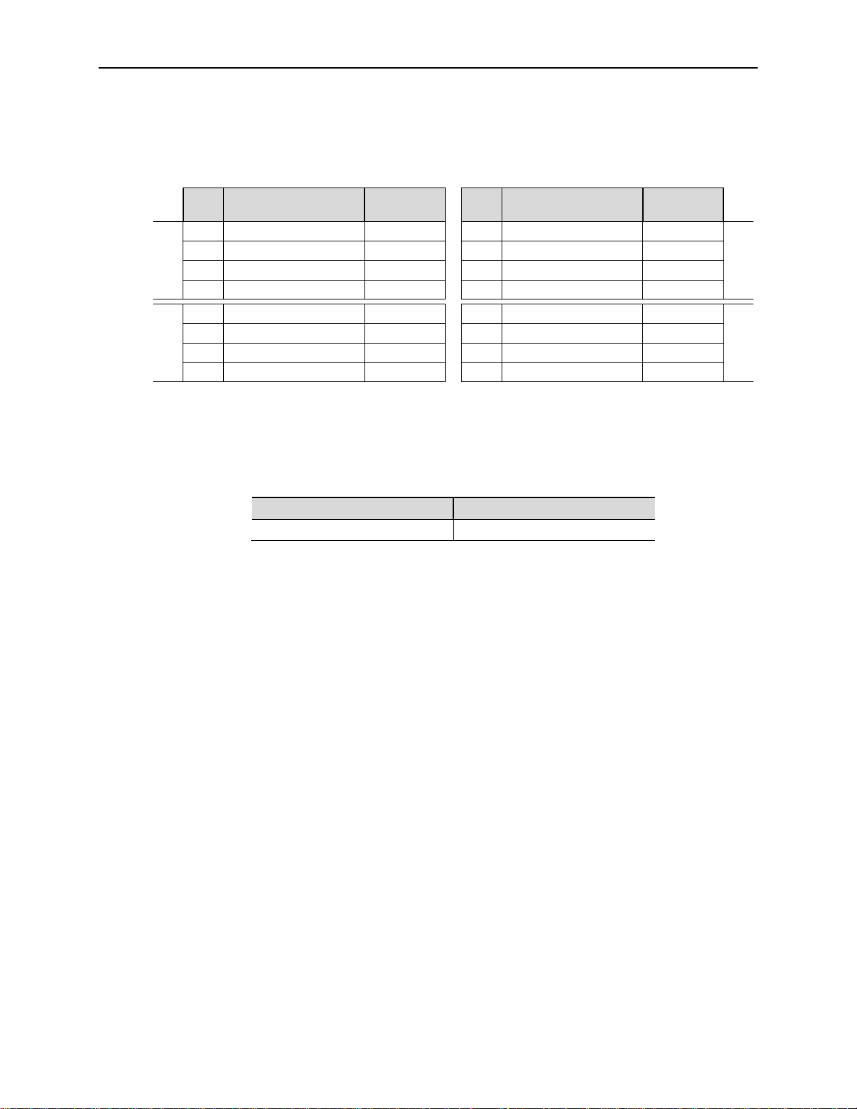
The next table lists the pinout of the Ethernet connector.
Table 14. Ethernet Connector Pinout
Pin 10/100 Signals
1 + Auto Switch (Tx or Rx) BI_DA+ 2 - Auto Switch (Tx or Rx) BI_DA3 + Auto Switch (Tx or Rx) BI_DB+ 4 + Auto Switch (Tx or Rx) BI_DC+
5 - Auto Switch (Tx or Rx) BI_DC- 6 - Auto Switch (Tx or Rx) BI_DB-
Port 0
7 + Auto Switch (Tx or Rx) BI_DD+ 8 - A uto Switch (Tx or Rx) BI_DD-
9 - Auto Switch (Tx or Rx) BI_DD- 10 + Aut o S witch (Tx or Rx) BI_DD+
11 - Auto Switch (Tx or Rx) BI_DB- 12 + Auto Switch (Tx or Rx) BI_DB+
13 - Auto Switch (Tx or Rx) BI_DC- 14 + Auto Switch (Tx or Rx) BI_DC+
Port 1
15 - Auto Switch (Tx or Rx) BI_DA- 16 + Auto Switch (Tx or Rx) BI_DA+
10/100/1000
Signals
Pin 10/100 Signals
10/100/1000
Signals
Cabling
An adapter cable, part number CBR-1604, is available. This is a 12-inch, 16-pin Click-Mate to
two RJ-45 connector cables.
If your application requires a custom cable, the following information will be useful:
EPU-4460 Board Connector Mating Connector
Molex 503148-1690 Molex 503149-1600
Port 0
Port 1
46 VL-EPU-4460 Reference Manual
Page 47
Ethernet Status LED
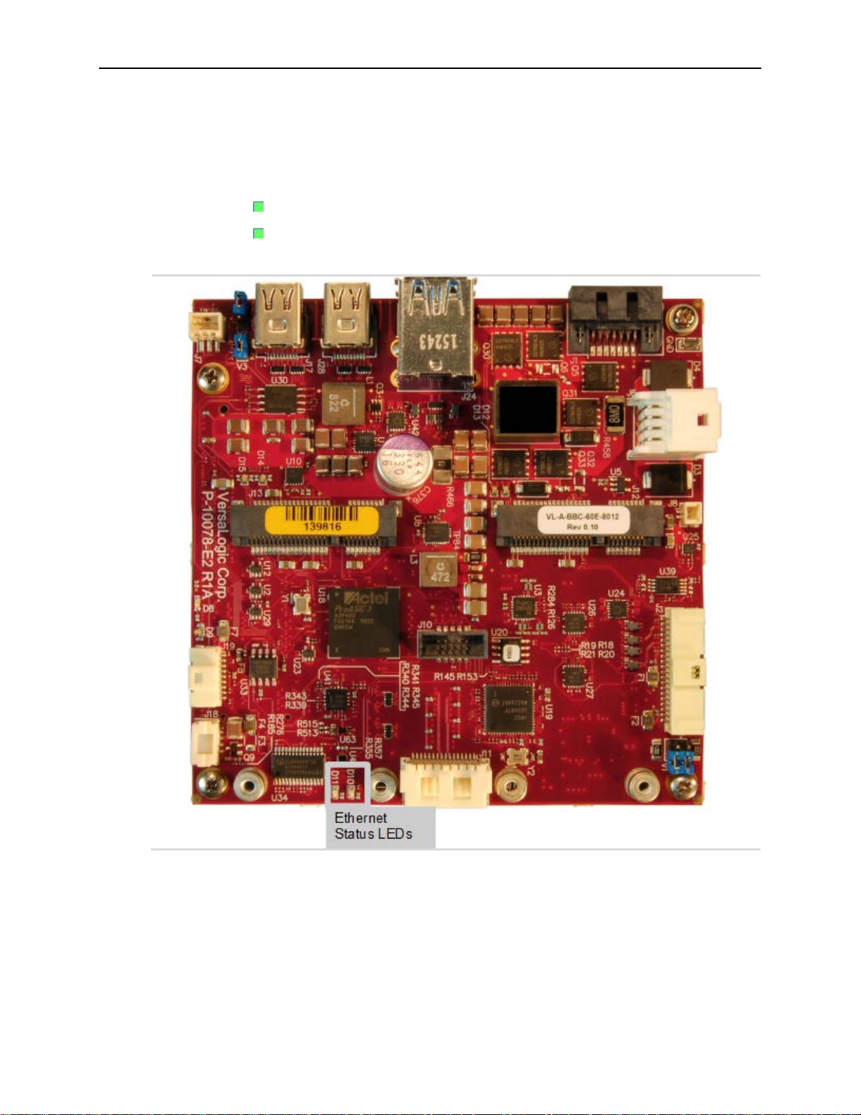
The figure below shows the location of the Ethernet status LED.
Network Interfaces
LED D10 –
LED D11 –
Figure 22. Onboard Ethernet Status LEDs
indicates link is good and blinks to show activity for Ethernet Port 0
indicates link is good and blinks to show activity for Ethernet Port 1
VL-EPU-4460 Reference Manual 47
Page 48
VL-CBR-4005B Paddleboard
9
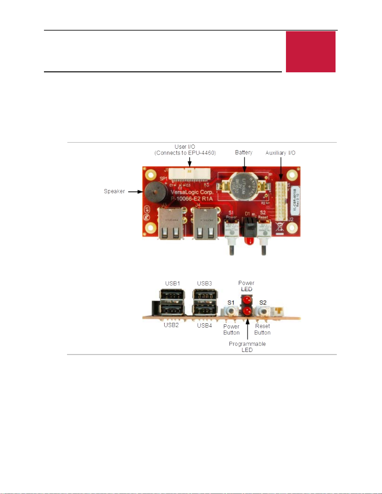
VL-CBR-4005B Connectors and Indicators
The next figure shows the locations of the connectors, switches, and LEDs on the VL-CBR4005B paddleboard.
Figure 23. VL-CBR-4005B Connectors, Switches, and LEDs
VL-CBR-4005B Paddleboard
48 VL-EPU-4460 Reference Manual
Page 49
VL-CBR-4005B Paddleboard
Pin
Signal
Pin
Signal
1
V5_USB1-2 (Note 1)
2
GND
3
USB1_P
4
USB2_P
5
USB1_N
6
USB2_N
7
V5_USB3-4 (Note 2)
8
GND
9
USB3_P
10
USB4_P
11
USB3_N
12
USB4_N
13
V3P3_S0 (Note 3)
14
GND
15
SPKR#
16
PLED#
17
PWR_BTN#
18
RST_BTN#
19
GND
20
GND
21
I2C_SCK
22
V_BATT
23
I2C_SDA
24
V_BATT Return
25
GND
26
GND
27
GPIO1
28
GPIO2
29
GPIO3
30
GPIO4
31
GND
32
GND
33
GPIO5
34
GPIO6
35
GPIO7
36
GPIO8
37
V3P3_SX (Note 4)
38
GND
39
ETH_LED1
40
ETH_LED2
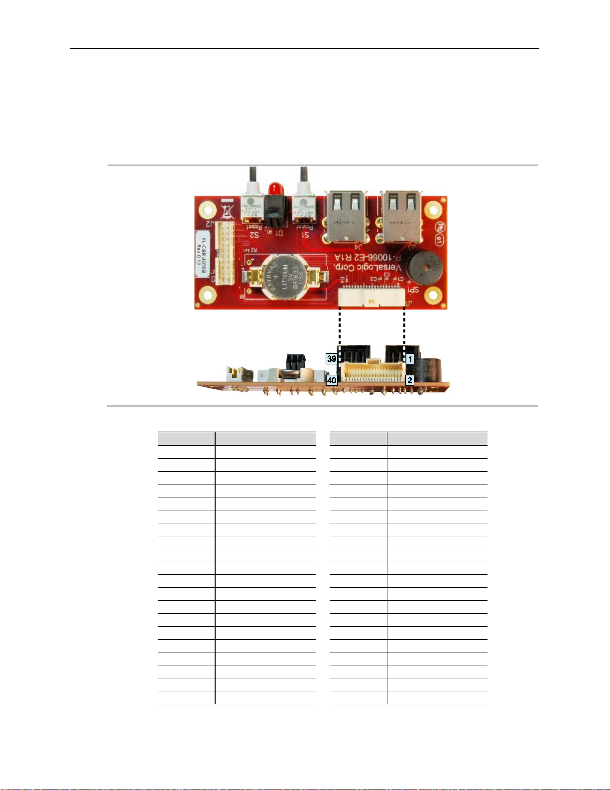
User I/O Connector
The following figure shows the location and pin orientation of the user I/O connector.
Figure 24. Location and Pin Orientation of the User I/O Connector
Table 15. User I/O Connector Pinout
VL-EPU-4460 Reference Manual 49
Page 50
VL-CBR-4005B Paddleboard
Notes:
be powered by a 3.3 V power source.
To prevent shorting, premat ur e failure or damage to the Lithium battery, do not
battery in fire. Dispose of used batteries promptly.
1. This is the +5V VBUS power for USB Port 1 and 2.
2. This is the +5V VBUS power for USB Port 3 and 4.
3. This 3.3 V power goes off in sleep modes. The SPKR# uses this power as
should the PLED# (there is no requirement for PLED# to use this power, but the
VL-CBR-4005B paddleboard does).
4. This 3.3 V power can be turned on or off similar to the 3.3V power to the Mini
Card via the FPGA (can go off in sleep modes or always stay on; by default it
goes off in sleep modes). It is used for the 10 kΩ pullup resistor power on the 8x
GPIOs and usually for the 2x Ethernet LEDs, however, the Ethernet LEDs can
Cabling
An adapter cable, part number CBR-4005A, is available for connecting the VL-CBR-4005B
paddleboard to the EPU-4460. This is a 12-inch, Pico-Clasp 40-pin to 40-pin cable
If your application requires a custom cable, the following information will be useful:
CBR-4005B Board Connector Mating Connector
Molex 501571-4007 Molex 501189-4010
On-board Battery
CAUTION:
place the board on a conductive surface such as metal, black conductive foam
or the outside surface of a metalized ESD protective pouch. The Lithium battery
may explode if mistreated. Do not recharge, disas sem ble, or dispos e of the
Nominal battery voltage is 3.0 V. If the voltage drops below 2.7 V, contact the factory for a
replacement. The life expectancy under normal use is approximately five years.
50 VL-EPU-4460 Reference Manual
Page 51
VL-CBR-4005B Paddleboard
Pin
Signal
Pin
Signal
1
I2C Clock
2
V_BATT
3
I2C Data
4 V_BATT_RETURN
5
GND
6
GND
7
GPIO1
8
GPIO2
9
GPIO3
10
GPIO4
11
GND
12
GND
13
GPIO5
14
GPIO6
15
GPIO7
16
GPIO8
17
+3.3 V
18
GND
19
Ethernet Port 0 LED
20
Ethernet Port 1 LED
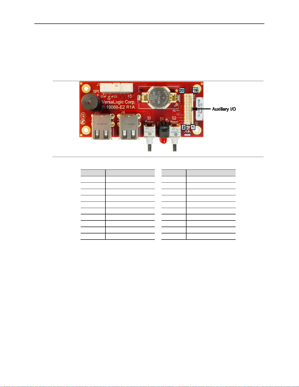
Auxiliary I/O Connector
This figure shows the location and pin orientation of the auxiliary I/O connector.
Figure 25. Location and Pin Orientation of Auxiliary I/O Connector
Table 16. Auxiliary I/O Connector Pinout
VL-EPU-4460 Reference Manual 51
Page 52
VL-CBR-4005B Paddleboard
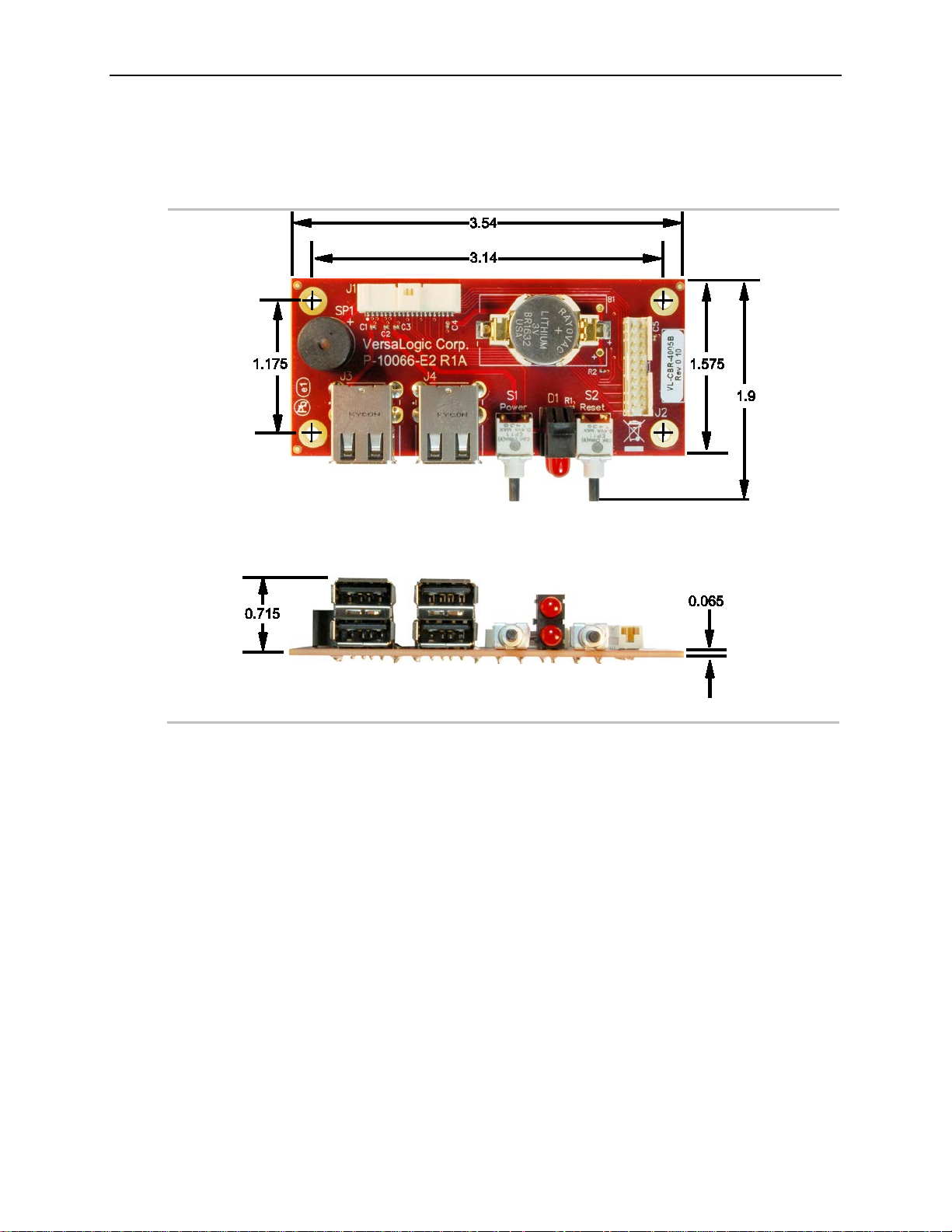
Dimensions and Mounting Holes
Figure 26. VL-CBR-4005B Dimensions and Mounting Holes
52 VL-EPU-4460 Reference Manual
Page 53
Thermal Considerations
By itself, the heat plate is not a complete thermal solution. Integrators should either implement a
85 ºC.
The heat plate is permanently affixed to the Condor and must not be removed. Removal of the
voids the product warranty and can damage the CPU.
10
Thermal Considerations
This chapter discusses the following topics related to thermal issues:
Selecting the correct thermal solution for your application
EPU-4460 thermal characterization
Installing the passive (HDW-416 heat sink), the active (HDW-415 fan), thermal solutions
available from VersaLogic
Selecting the Correct Thermal Solution for Your Application
This section provides guidelines for the overall system thermal engineering effort.
Heat Plate
The heat plate supplied with the Condor is the basis of the thermal solution. The heat plate draws
heat away from the CPU chip as well as other critical components. Some components rely on the
ambient air temperature at or below the maximum specified 85 ºC temperature.
The design of the heat plate assumes that the user’s thermal solution will maintain the top surface
of the heat plate at 90 ºC or less. If that temperature threshold is maintained, the CPU will remain
safely within its operating temperature limits.
CAUTION:
thermal solution using the accessories available from VersaLogic or develop their own thermal
solution that attaches to the heat plate, suitable for environments in which the EPU-4460 will be
used. As stated above, the thermal solution must be capable of keeping the top surface of the
heat place at or below 90 ºC and the air surrounding the components in the assembly at or below
heat plate voids the product warranty. Attempting to operate the Condor without the heat plate
System-level Considerations
The Condor is often mounted directly to another thermally controlled surface via its heat plate
(that is, the inside surface of an enclosure). In this case, the user needs to maintain the heat plate
at or below 90 ºC by controlling the mounting surface temperature. The EPU-4460 thermal
solutions available from VersaLogic – the HDW-406 heat sink with or without the HDW-415
fan, or the HDW-408 heat pipe block – can be used in the user’s final system or only used during
product development as a temporary bench-top solution.
The ambient air surrounding the EPU-4460 needs to be maintained at 85 ºC or below. This may
prove to be challenging depending on how and where the EPU-4460 is mounted in the end user
system.
VL-EPU-4460 Reference Manual 53
Page 54
Thermal Considerations
At this temperature, the CPU cores throttle back to a lower speed. This
speed.
At this temperature, the operating system typically puts the board into a
sleep or other low-power state.
The CPU turns itself off when this temperature is reached. This is a fixed
trip point and cannot be adjusted.
Notes:
2. The default value in the BIOS Setup utility for this trip point is 100 ºC.
The decision which thermal solution to use relies on several factors including:
Number of CPU cores in the SoC (single, dual, or quad)
CPU and video processing utilization by the user application
Temperature range within which the EPU-4460 will be operated
Air movement (or lack of air movement)
Most of these factors involve the demands of the user application on the EPU-4460 and cannot
be isolated from the overall thermal performance. Due to the interaction of the user application,
the Condor thermal solution, and the overall environment of the end system, thermal
performance cannot be rigidly defined.
The ambient air surrounding the EPU-4460 needs to be maintained at 85 ºC or below. This would
include the space between the two main boards as well as the space beneath an installed Mini
PCIe expansion board. Standard methods for addressing this requirement include the following:
Provide a typical airflow of 100 linear feet per minute (LFM) / 0.5 linear meters per second
(as described in the section titled EPU-4460 Thermal Characterization, beginning on page
56) within the enclosure
Position the EPU-4460 board to allow for convective airflow
Lower the system level temperature requirement as needed
CPU Thermal Trip Points
The CPU cores in the Condor have their own thermal sensors. Coupled with these sensors are
specific reactions to three thermal trip points. Table 17 describes the three thermal trip points.
Note that these are internal temperatures that are about 10 ºC above the heat plate temperature.
Table 17. CPU Thermal Trip Points
Trip Point Description
Passive (Note 1)
Critical (Note 2)
Maximum core temperature
1. The default value in the BIOS Setup utility for this trip point is 90 ºC.
reduces the power draw and heat dissipation, but lowers the processing
These trip points allow maximum CPU operational performance while maintaining the lowest
CPU temperature possible. The long-term reliability of any electronic component degrades when
it is continually run near its maximum thermal limit. Ideally, the CPU core temperatures will be
kept well below 100 ºC with only brief excursions above.
CPU temperature monitoring programs are available to run under both Windows and Linux.
Table 18 lists some of these hardware monitoring programs.
54 VL-EPU-4460 Reference Manual
Page 55
Thermal Considerations
Operating System
Program Type
Description
Linux
lm-sensors
http://en.wikipedia.org/wiki/Lm_sensors
With Heat Sink
(HDW-416)
With Heat Sink + Fan
(HDW-416 + HDW-415)
VL-EPU-4460-EAP
-40 ° to +85 °C
-40 ° to +85 °C
-40 ° to +85 °C
VL-EPU-4460-EBP
-40 ° to +85 °C
-40 ° to +85 °C
-40 ° to +85 °C
VL-EPU-4460-ECP
-40 ° to +85 °C
-40 ° to +85 °C
-40 ° to +85 °C
Table 18. Temperature Monitoring Programs
Core Temperature http://www.alcpu.com/CoreTemp/
Windows
Hardware Monitor http://www.cpuid.com/softwares/hwmonitor.html
Open Hardware Monitor http://openhardwaremonitor.org/
Thermal Specifications, Restrict i ons, and Condi t ions
Graphical test data is in the section titled EPU-4460 Thermal Characterization, beginning on
page 56. Refer to that section for the details behind these specifications. These specifications are
the thermal limits for using the EPU-4460 with one of the defined thermal solutions.
Due to the unknown nature of the entire thermal system, or the performance requirement of the
application, VersaLogic cannot recommend a particular thermal solution. This information is
intended to provide guidance in the design of an overall thermal system solution.
Table 19. Absolute Minimum and Maximum Air Temperatures
Board With Heat Plate
Overall Restrictions and Conditions:
Ranges shown assume less than 90% CPU utilization.
Keep the maximum CPU core temperature below 100ºC.
The ambient air surrounding the EPU-4460 needs to be maintained at 85 ºC or below. This
includes the space between the two main boards as well as the space beneath an installed
Mini PCIe expansion board. A required overall airflow of 100 linear feet per minute (LFM) /
0.5 linear meters per second (LMS) addresses this requirement. If this air flow is not
provided, other means must be implemented to keep the adjacent air at 85 ºC or below.
Heat Plate Only Restrictions and Conditions:
The heat plate must be kept below 90 °C. This applies to a heat plate mounted directly to
another surface as well as when the HDW-408 heat pipe block is used.
Heat Sink Only Considerations:
At 85°C air temperature and 90% CPU utilization, there will be little if any thermal margin
to a CPU core temperature of 100 °C or the passive trip point (see test data). If this is the use
case, consider adding a fan or other additional airflow.
VL-EPU-4460 Reference Manual 55
Page 56
Thermal Considerations
Integrator’s Note: The ambient air surrounding the EPU-4460 needs to be maintained
at 85 °C or below.
EPU-4460 (Condor) dual core CPU with:
(Note)
Critical thermal trip point setting: 111 ºC
Operating System
Microsoft Windows 10 Enterprise
- Primarily used to read the CPU core temperature
Thermal chamber
Note:
Heat Sink with Fan Considerations:
The heat sink and fan combination cools the CPU when it is running in high temperature
environments, or when the application software is heavily utilizing the CPU or video
circuitry. The fan assists in cooling the heat sink and provides additional air movement
within the system.
EPU-4460 Thermal Characterization
The EPU-4460 board underwent the following thermal characterization tests:
Test Scenario 1: Dual core EPU-4460-EAP (Active and passive)
Test Scenario 2: Dual core EPU-4460-EBP (Active and passive)
Test Scenario 3: Dual core EPU-4460-ECP (Active and passive)
This table describes the thermal testing setup for the board.
Table 20. EPU-4460 Thermal Testing Setup
Hardware
Configuration
BIOS
Test Software
Test Environment
This device connects through a VersaLogic VL-CBR-4005B paddleboard.
The test results reflect the test environment within the temperature chamber used. The airflow of
this particular chamber is about 0.5 linear meters per second (~100 linear feet per minute).
Thermal performance improves by increasing the airflow beyond 0.5 linear meters per second.
32 GB of DDR4 DRAM (2 GB for the single- and dual-core board models)
HDW-416 (passive heat sink)
HDW-415 (heat sink fan)
One VGA display device (connected through the LVDS interface), one
display for monitor
One SATA hard disk drive
Two RS-232 ports in loopback configuration
Two VersaLogic VL-MPEe-E3 Mini PCIe Gigabit Ethernet modules
Two active Ethernet ports in loopback configuration
Two USB 2.0 ports in loopback configuration (Note)
USB keyboard and mouse
VER2C101
Passive thermal trip point setting: 105 ºC
Passmark BurnIn Test v8.1 b1018
- CPU utilization ~90%
Intel Thermal Analysis Tool (TAT) v5.0.1026
56 VL-EPU-4460 Reference Manual
Page 57
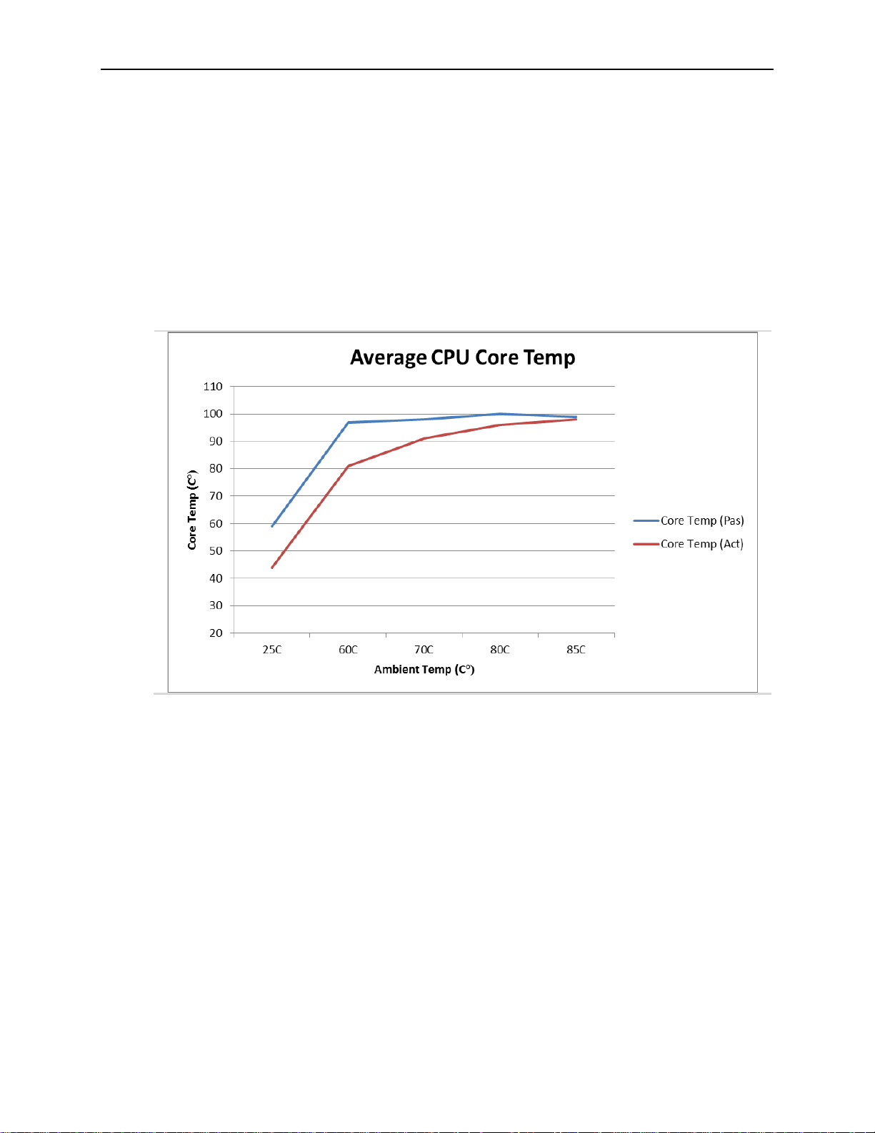
Thermal Considerations
The system power dissipation is primarily dependent on the application program; that is, its use
of computing or I/O resources. The stress levels used in this testing are at the top of the range of
a typical user’s needs.
Test Results
Test Scenario 1: Dual Core EPU-4460-EAP + HDW-416 Heat Sink, with/without HDW-415 fan
The thermal characterization for the EPU-4460-EAP model (Intel Core i3) is shown below.
Figure 27. EPU-4460-EAP Dual Core Temperature Relative to Ambient Temperature
VL-EPU-4460 Reference Manual 57
Page 58
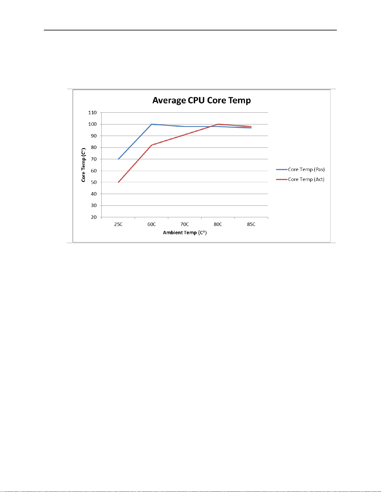
Thermal Considerations
Test Scenario 2: Dual Core EPU-4460-EBP + HDW-416 Heat Sink, with/without HDW-415 fan
The thermal characterization for the EPU-4460-EBP model (Intel Core i5) is shown below.
Figure 28. EPU-4460-EBP Dual Core Temperature Relative to Ambient Temperature
58 VL-EPU-4460 Reference Manual
Page 59
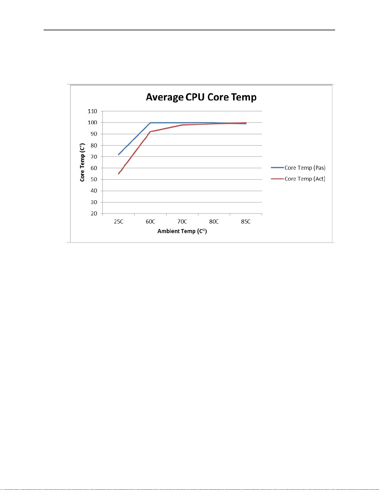
Thermal Considerations
Test Scenario 3: Dual Core EPU-4460-EDP + HDW-416 Heat Sink, with/without HDW-415 Fan
Figure 29. EPU-4460-ECP Dual Core Temperature Relative to Ambient Temperature
Installing VersaLogic Thermal Solutions
The following thermal solution accessories are available from VersaLogic:
VL-HDW-401 Thermal Compound Paste – used to mount the heat sink to the heat plate
VL-HDW-416 Passive Heat Sink – mounts to standard product.
VL-HDW-415 Fan Assembly – Cooling fan for the HDW-416 passive heatsink. Operates at
+12 V and includes an EPU-4460 compatible connector
VL-HDW-408 Heat Pipe Block – mounts to heat plate
Hardware Assembly
There are two basic assembly methods:
Heat plate down (in relation to the enclosure)
Heat plate up
These assembly methods are shown in Figure 30 and Figure 31respectively.
Heat Plate Down
The next figure (a representative image of a similar VersaLogic product) shows the assembly.
Use this assembly method if you are attaching the Condor to a larger thermal solution such as a
metal chassis/enclosure.
VL-EPU-4460 Reference Manual 59
Page 60
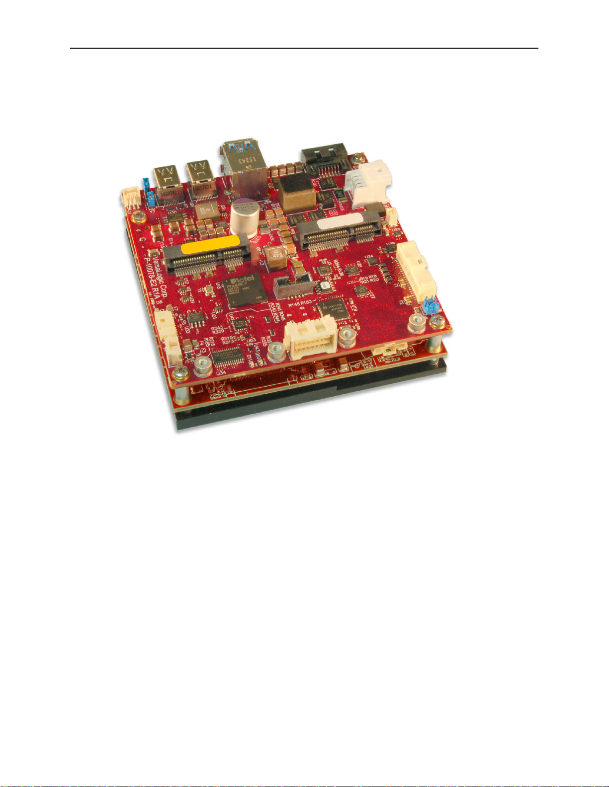
Thermal Considerations
1. Attach the baseboard to the enclosure with standoffs.
Figure 30. Heat Plate Down
60 VL-EPU-4460 Reference Manual
Page 61
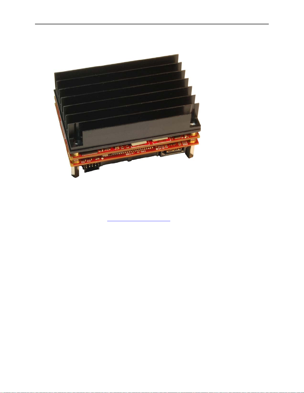
Figure 31. Example of Heat Plate Up with a Heat Sink
Thermal Considerations
Installing the VL-HDW-416 Passi ve Heat Sink
1. Apply the Arctic Silver* Thermal Compound (VL-HDW-401)
Apply the thermal compound to the heat plate using the method described on the Arctic
Silver website - http://www.arcticsilver.com/
2. Position the passive heat sink
Using the figure below as a guide, align the five mounting holes of the heat sink with the
heat plate.
Orient the heat sink fins in the direction of the system airflow to maximize CPU cooling.
3. Secure the passive heat sink to the heat plate
Affix the passive heat sink to the heat plate using five M2.5 pan head screws.
Using a torque screwdriver, tighten the screws to 4.0 inch-pounds.
VL-EPU-4460 Reference Manual 61
Page 62
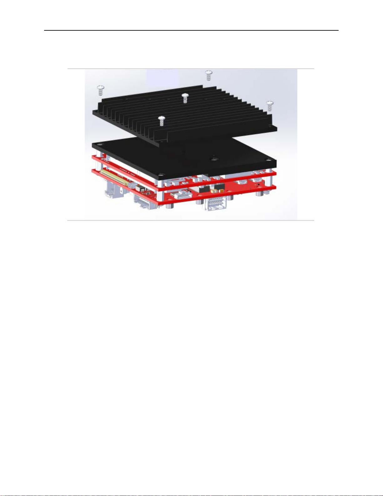
Thermal Considerations
Figure 32. Installing the Passive Heat Sink
62 VL-EPU-4460 Reference Manual
Page 63
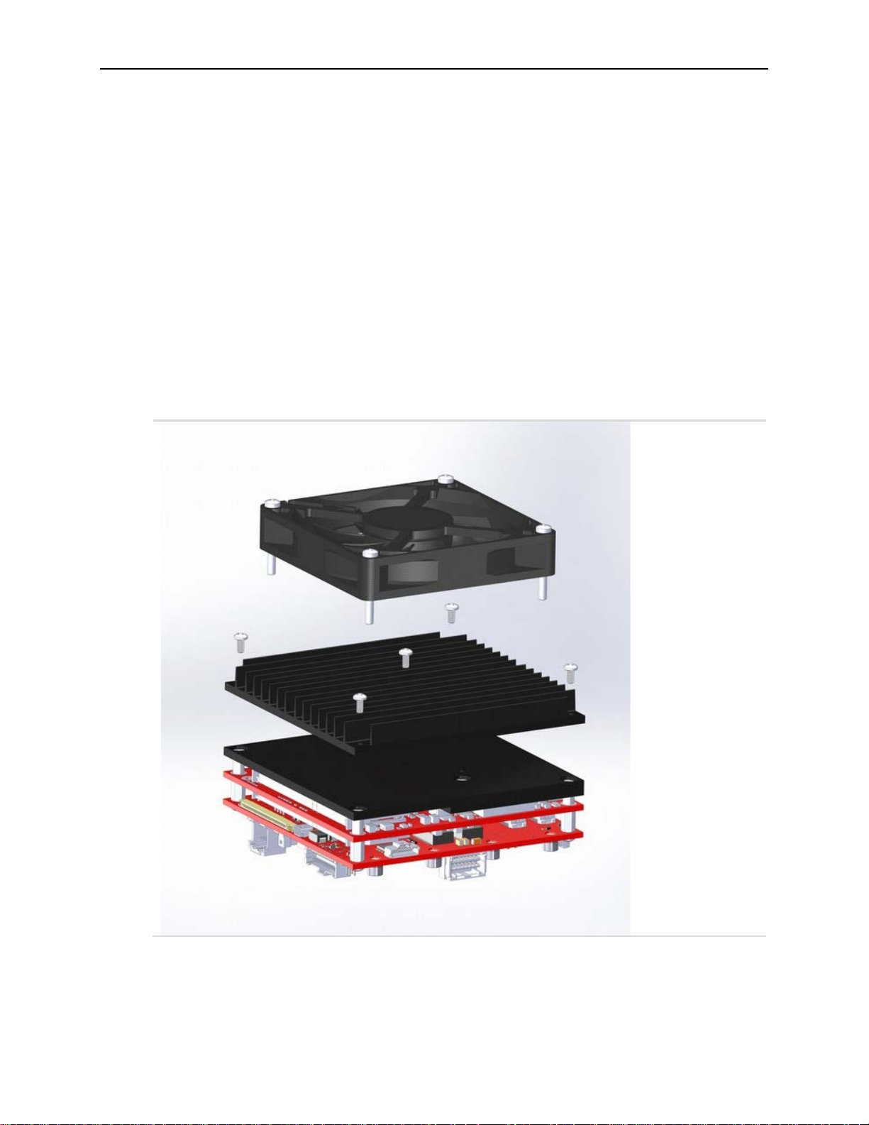
Thermal Considerations
Installing the VL-HDW-415 Heat Si nk Fan
1. Position the fan assembly
Using the figure below as a guide, align the mounting holes of the heat sink fan with the
four holes in the passive heat sink. Position the fan so that its power cable can easily
reach its mate.
2. Secure the fan to the heat sink
Affix the heat sink fan using four M3 pan head screws.
Using a torque screwdriver, tighten the screws to 4.0 inch-pounds.
3. Connect power to the fan
Connect the fan’s power cable to J18 on the EPU-4460.
Figure 33. Installing the Heat Sink Fan
VL-EPU-4460 Reference Manual 63
 Loading...