


DVRT36
Homeowner's Installation &
Operating Manual
INSTALLER: DO NOT DISCARD THIS MANUAL - LEAVE FOR HOMEOWNER
Direct Vent
Models: DVRT36
DVRT39
DVRT43
INSTALLER/CONSUMER
SAFETY INFORMATION
PLEASE READ THIS MANUAL
BEFORE INSTALLING AND
USING APPLIANCE
WARNING!
IF THE INFORMATION IN THIS
MANUAL IS NOT FOLLOWED EX-
ACTLY, A FIRE OR EXPLOSION MAY
RESULT CAUSING PROPERTY
DAMAGE, PERSONAL INJURY OR
LOSS OF LIFE.
FOR YOUR SAFETY
Installation and service must
be performed by a qualified
installer, service agency or the
gas supplier.
WHAT TO DO IF YOU SMELL
GAS:
• Do not try to light any appliance.
• Do not touch any electric switch;
do not use any phone in your
building.
• Immediately call your gas
supplier from your neighbor's
phone. Follow the gas suppliers
instructions.
• If you cannot reach your gas
supplier call the fire department.
DO NOT STORE OR USE
GASOLINE OR OTHER FLAM-
MABLE VAPORS AND LIQUIDS
IN THE VICINITY OF THIS OR
ANY OTHER APPLIANCE.
D
E
S
I
G
N
C
E
R
T
I
F
I
E
D
10002428 11/03 Rev. 5
CERTIFIED
410 Admiral Blvd. • Mississauga, Ontario, Canada L5T 2N6 • 905-670-7777
www.majesticproducts.com • www.vermontcastings.com
Vermont Castings, Majestic Products

2
Vermont Castings, Majestic Products DVRT36/39/ 43
10002428
Installation & Operating Instructions
General Information .......................................................................................................................... 3
Locating Your Fireplace.................................................................................................................... 3
Fireplace Dimensions ....................................................................................................................... 4
Clearance to Combustibles .............................................................................................................. 6
Mantels ............................................................................................................................................ 6
Hearth ............................................................................................................................................ 6
Framing & Finishing.......................................................................................................................... 7
Final Finishing................................................................................................................................... 7
Gas Specifications ............................................................................................................................ 7
Gas Inlet and Manifold Pressures.................................................................................................. 7
High Elevations ................................................................................................................................. 7
Gas Line Installation ......................................................................................................................... 8
Remote ON/OFF Switch Installation ................................................................................................ 8
Alternate Switch Location ................................................................................................................. 8
EB-1 Electrical Box ........................................................................................................................... 9
Electronic Gas Control Valve............................................................................................................ 9
Optional Top Vent Application........................................................................................................ 10
Installing the DVRT36RMH in a Mobile Home ............................................................................... 10
Venting Installation Instructions
General Venting .............................................................................................................................. 11
General Venting Information -Termination Clearances ................................................................. 12
General Information for Connecting Vent Pipes ............................................................................ 13
Crimped End Pipes......................................................................................................................... 13
Twist-lock Pipes .............................................................................................................................. 14
How to use the Vent Graph ............................................................................................................ 14
Rear Wall Vent Application............................................................................................................. 14
Rear Wall Vent Installation ............................................................................................................. 15
Vertical Sidewall Application .......................................................................................................... 16
Vertical Sidewall Installation........................................................................................................... 17
Below Grade Installation................................................................................................................. 18
Vertical Through-the-Roof Application ...........................................................................................19
Vertical Through-the-Roof Installation............................................................................................ 20
Gravity Ducting System .................................................................................................................. 21
Clearance to Combustibles ............................................................................................................ 21
Venting Components, Twist-lock & Crimp End .............................................................................. 23
Operating Instructions
Glass Information............................................................................................................................ 25
Louvre Removal.............................................................................................................................. 25
Window Frame Assembly Removal ............................................................................................... 25
Glass Cleaning................................................................................................................................ 25
Installation of Logs & Lava Rock .................................................................................................... 26
Flame & Temperature Adjustment ................................................................................................. 27
Flame Characteristics ..................................................................................................................... 27
Inspecting the Venting System ....................................................................................................... 28
Lighting and Operating Instructions ............................................................................................... 29
Instructions for RF Comfort Control Valve ..................................................................................... 31
Auto Path Chart .............................................................................................................................. 33
Comfort Valve System Control Sequence of Operation with Transmitter ..................................... 34
Troubleshooting Guide ................................................................................................................... 35
Fuel Conversion Instructions .......................................................................................................... 38
Maintenance
Cleaning the Standing Pilot Control System .................................................................................. 39
Replacement Parts....................................................................................................................................... 40
Optional Accessories
Fan Kits .......................................................................................................................................... 43
Hard (Direct) Wire Hookup ............................................................................................................. 43
Remote Controls. ............................................................................................................................ 44
Ceramic Refractory Panels............................................................................................................. 44
Decorative Bay Window.................................................................................................................. 44
Decorative Frame Trim ................................................................................................................... 45
For Use in Mobile Homes: Model DVRT36MH ......................................................................................... 46
Warranty........................................................................................................................................................ 48
Energuide...................................................................................................................................................... 50
Table of Contents
Thank You and Congratulations on your purchase of a Vermont Castings, Majestic Products Fireplace.
IMPORTANT: Read all instructions and warnings carefully before starting installation. Failure to follow
these instructions may result in a possible fire hazard and will void the warranty.
PLEASE READ THE INSTALLATION & OPERATING INSTRUCTIONS BEFORE USING THE APPLIANCE.
3
10002428
Vermont Castings, Majestic Products DVRT36/39/ 43
This gas appliance should be installed by a qualified
installer in accordance with local building codes and with
current CSA-B149.1 Installation codes for Gas Burning
Appliances and Equipment. If the unit is being installed in
a mobile home, the installation should comply with the
current CAN/ CSA Z240.4 code. For U.S.A. Installations
follow local codes and/ or the current National Fuel Gas
Code, ANSI Z223.1/NFPA 54.
FOR SAFE INSTALLATION AND OPERATION, NOTE
THE FOLLOWING:
1. This fireplace gives off high temperatures and should
be located out of high traffic areas and away from
furniture and draperies.
2. Children and adults should be alerted to the hazards
of the high surface temperatures of this fireplace and
should stay away to avoid burns or ignition of clothing.
3. Children should be carefully supervised when in the
same room as your fireplace.
4. Under no circumstances should this fireplace be
modified. Parts removed for servicing should be
replaced prior to operating this fireplace again.
5. Installation and any repairs to this fireplace must be
performed by a qualified installer, service agency or
gas supplier. A professional service person should be
contacted to inspect this fireplace annually. Make it a
practice to have all of your gas fireplaces checked
annually. More frequent cleaning may be required due
to excess lint and dust from carpeting, bedding
material, etc.
6. Control compartments, burners and air passages in
this fireplace should be kept clean and free of dust
and lint. Make sure the gas valve and pilot light are
turned off before you attempt to clean this fireplace.
7. The venting system (chimney) of this fireplace should
be checked at least once a year and if needed your
venting system should be cleaned.
8. Keep the area around your fireplace clear of
combustible materials, gasoline and other flammable
vapor and liquids. This fireplace should not be used
as a drying rack for clothing, nor should Christmas
stockings or decorations be hung in the area of it.
9. Under no circumstances should any solid fuels (wood,
coal, paper or cardboard etc.) be used in this fire-
place.
10. The flow of combustion and ventilation air must not be
obstructed in any way.
11. When fireplace is installed directly on carpeting, vinyl
tile or any combustible material other than wood, this
fireplace must be installed on a metal or wood panel
extending the full width and depth of the fireplace.
12. This fireplace requires adequate ventilation and
combustion air to operate properly.
13. This fireplace must not be connected to a chimney
flue serving a separate solid fuel burning fireplace.
14. When the fireplace is not in use it is recommended
that the gas valve be left in the “OFF” position.
Installation & Operating Instructions
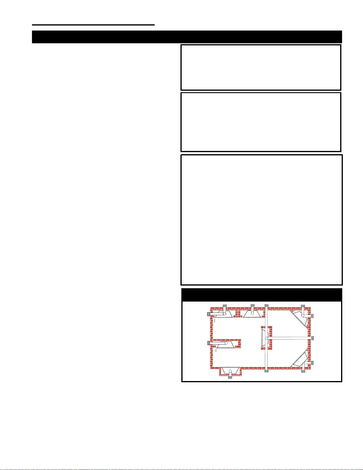
A) Flat on wall B) Cross corner C) Island
**
D) Room divider
*
/
**
E) Flat on wall corner
*
F) Chase installation
Y) 6 in. minimum
N
otes (Fig. 1):
*
When you install your Vermont Castings, Majestic Products fireplace in
(D) Room divider or (E) Flat on wall corner positions, a minimum of (Y),
6 in. (153 mm) clearance must be maintained from the perpendicular
wall and the front of the fireplace.
**
Island (C) and Room Divider (D) installation is possible if the horizontal
portion of the vent system (X) does not exceed 20 ft. (610 cm). See
details in Venting Section.
This appliance may be installed in an aftermarket
permanently located, manufactured home or mobile home,
where not prohibited by local codes.
This appliance is only for use with the type of gas indi-
cated on the rating plate. This appliance is not convertible
for use with other gases, unless a certified kit is used.
The DVRT36RMH has been approved for mobile home
installations.
IMPORTANT:
PLEASE REVIEW THE FOLLOWING CAREFULLY
Remove any plastic from trim parts before turning the
fireplace “ON”.
It is normal for fireplaces fabricated of steel to give off
some expansion and/or contraction noises during the
start up or cool down cycle. Similar noises are found with
your furnace heat exchanger or car engine.
It is not unusual for your Vermont Castings, Majestic
Products gas fireplace to give off some odor the first time
it is burned. This is due to the curing of the paint and any
undetected oil from the manufacturing process.
Please ensure that your room is well ventilated - open
all windows.
It is recommended that you burn your fireplace for at
least ten (10) hours the first time you use it. If the optional
fan kit has been installed, place the fan switch in the
“OFF” position during this time.
Locating the Fireplace
Fig. 1 Locating the Gas Fireplace.
LU584-1
Y
E
A
B
C
D
F
Y
B
X
Proposition 65 Warning: Fuels used in gas, wood-
burning or oil fired appliances, and the products of
combustion of such fuels, contain chemicals known to
the State of California to cause cancer, birth defects and
other reproductive harm.
California Health & Safety Code Sec. 25249.6
4
Vermont Castings, Majestic Products DVRT36/39/ 43
10002428
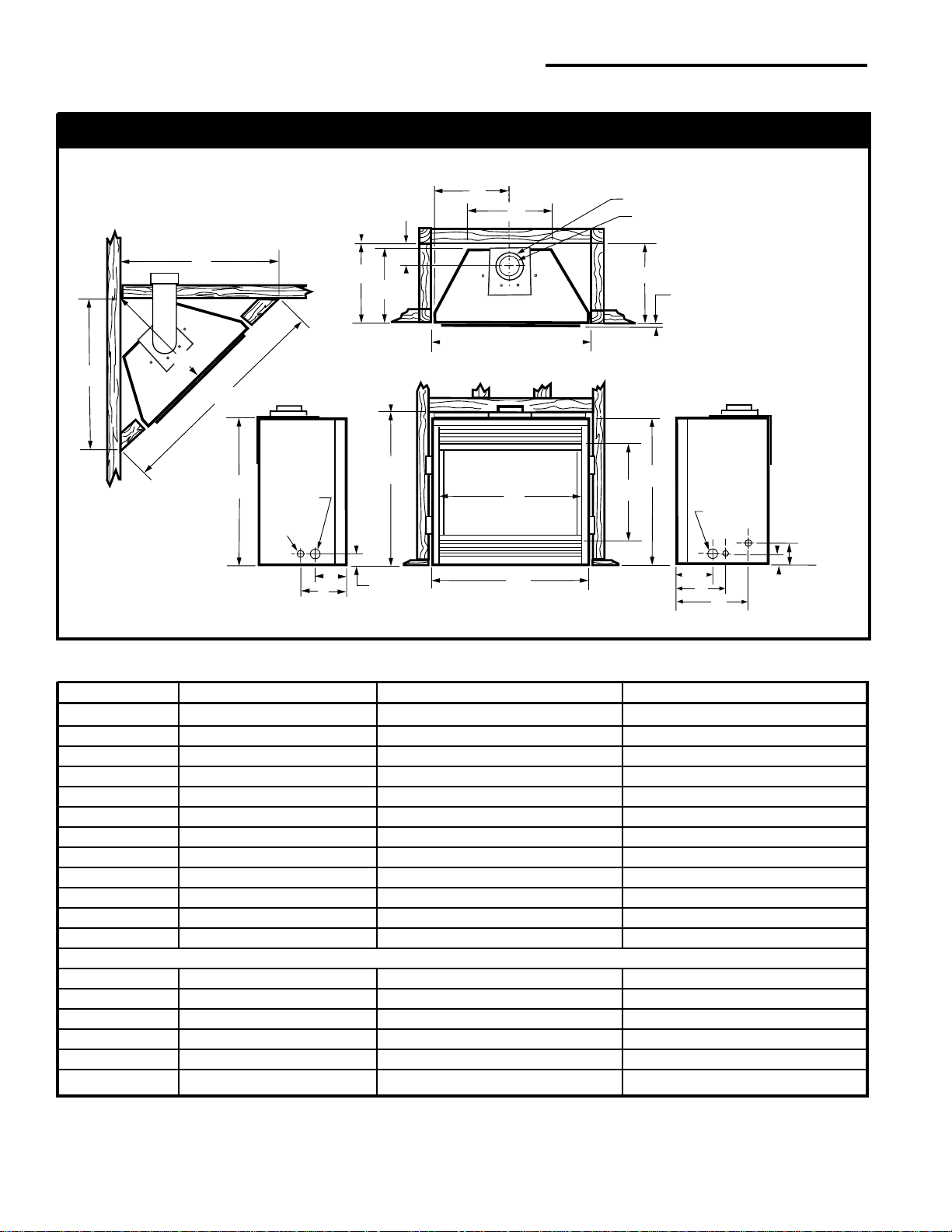
Fireplace Dimensions (Installed as Top Vent)
CFM188
Fig. 2 Fireplace specifications and framing dimensions.
5/
8
"
C
L
P - Rough Opening Width
7" Dia.
4" Dia.
5
¹⁄₂"
(140mm)
Rough
Opening
Height
Electrical
Access
Rough
Opening
Depth
Recessed
Nailing
Flange
Gas Line
Access
(178mm)
(102mm)
(16mm)
M
M
N
E
Q
C
A
F
D
G
O
I
J
K
C
L
O
I
J
2"
(51mm)
Gas Line
Access
2" (51mm)
4" (102mm)
R
Ref. DVRT36 DVRT39 DVRT43
A 36” (914mm) 39” (991mm) 43” (1092mm)
B37¹⁄₄” (946mm) 37¹⁄₄” (946mm) 40” (1016mm)
C34¹⁄₄” (870mm) 34¹⁄₄” (870mm) 37” (940mm)
D 21” (533mm) 21” (533mm) 23¹⁄₂” (597mm)
E32
₇
⁄₈” (835mm) 35
₇
⁄₈” (911mm) 39
₇
⁄₈” (1012mm)
F 20” (508mm) 24 ³⁄₈” (619mm) 31” (787mm)
G14¹⁄₄” (362mm) 15³⁄₄” (400mm) 16¹⁄₄” (412mm)
H6”(152mm) 6” (152mm) 6” (152mm)
I5¹⁄₂” (140mm) 5¹⁄₂” (140mm) 5¹⁄₂” (140mm)
J7³⁄₄” (197mm) 8¹⁄₂” (216mm) 8¹⁄₂” (216mm)
K10³⁄₄” (273mm) 12¹⁄₂” (318mm) 12¹⁄₂” (318mm)
L 18” (457mm) 19¹⁄₂” (495mm) 21¹⁄₂” (546mm)
Framing Dimensions
M 36” (914mm) 40” (1016mm) 44” (1118mm)
N 51” (1295mm) 56” (1422mm) 62¹⁄₄” (1581mm)
O14¹⁄₂” (368mm) 16¹⁄₂” (419mm) 16¹⁄₂” (419mm)
P36¹⁄₂” (927mm) 39¹⁄₂” (1003mm) 43¹⁄₂”(1105mm)
Q 35” (889mm) 35” (889mm) 37³⁄₄” (959mm)
R25¹⁄₂” (648mm) 28” (711mm) 36¹⁄₈” (918mm)
5
10002428
Vermont Castings, Majestic Products DVRT36/39/ 43
C
L
Q - Rough Opening Width
7" Dia.
4" Dia.
Rough
Opening
Height
Electrical
Access
Rough
Opening
Depth
Recessed
Nailing
Flange
Gas Line
Access
(178mm)
(102mm)
O
O
N
D
R
B
A
E
C
F
P
I
J
K
H
S
B
M
P
L
J
K
G
5/
8
" (16mm)
2"
(51mm)
2" (51mm)
4" (102mm)
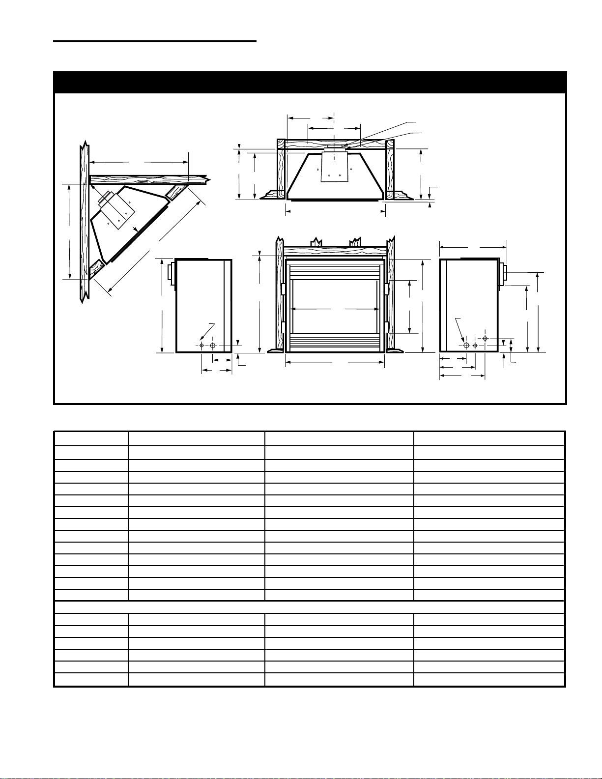
Fireplace Dimensions (Installed as Rear Vent)
CFM189
Fig. 3 Fireplace specifications and framing dimensions.
Ref. DVRT36 DVRT39 DVRT43
A 36” (914mm) 39” (991mm) 43” (1092mm)
B34¹⁄₄” (870mm) 34¹⁄₄” (870mm) 37” (940mm)
C 21” (533mm) 21” (533mm) 23¹⁄₂” (597mm)
D32
₇
⁄₈” (835mm) 35
₇
⁄₈” (911mm) 39
₇
⁄₈” (1012mm)
E 20” (508mm) 24³⁄₈” (610mm) 31” (787mm)
F14¹⁄₄” (362mm) 15³⁄₄” (400mm) 16” (406mm)
G16³⁄₄” (425mm) 18” (457mm) 18¹⁄₄” (464mm)
H25¹⁄₄” (641mm) 25¹⁄₄” (641mm) 28” (711mm)
I28³⁄₄” (730mm) 28³⁄₄” (730mm) 31¹⁄₂” (800mm)
J5¹⁄₂” (140mm) 5¹⁄₂” (140mm) 5¹⁄₂” (140mm)
K7³⁄₄” (197mm) 8¹⁄₂” (216mm) 8¹⁄₂” (216mm)
L10³⁄₄” (273mm) 12¹⁄₂” (318mm) 12¹⁄₂” (318mm)
M 18” (457mm) 19¹⁄₂” (495mm) 21¹⁄₂” (546mm)
Framing Dimensions
N59⁹⁄₁₆” (1436mm) 62¹⁄₄” (1581mm) 68¹⁄₂” (1740mm)
O 40” (1016mm) 44” (1118mm) 48” (1219mm)
P14¹⁄₂” (368mm) 16¹⁄₂” (419mm) 16¹⁄₂” (419mm)
Q36¹⁄₂” (927mm) 39¹⁄₂” (1003mm) 43¹⁄₂”(1105mm)
R 35” (889mm) 35” (889mm) 37³⁄₄” (959mm)
S25¹⁄₂” (648mm) 28” (711mm) 36¹⁄₈” (918mm)
6
Vermont Castings, Majestic Products DVRT36/39/ 43
10002428
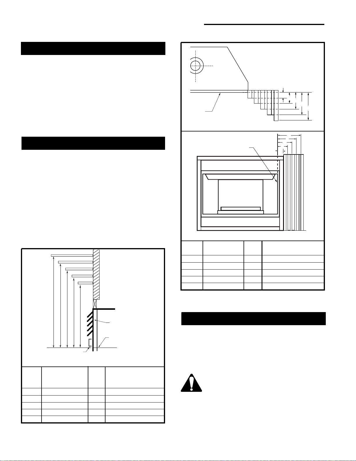
Mantels
The height a combustible mantel is fitted above the
fireplace is dependent on the depth of the mantel. This
also applies to the distance between the mantel leg (if
fitted) and the fireplace.
Refer to Figures 4a and 4b and the Mantel Charts
below them for correct mounting heights and widths.
• The distances and reference points are not
affected by the fitting of a bay window front trim kit.
• Noncombustible mantels and legs may be
installed at any height and width around the
appliance.
•When using paint or lacquer to finish the mantel, it
must be heat-resistant to prevent discoloration.
Clearance to Combustibles
Appliance
Top ............................................................ 0” (0mm)
Bottom....................................................... 0” (0mm)
Side ........................................................... 0” (0mm)
Back ..........................................................0” (0mm)
Venting
Concentric sections of DV Vent...................1” (25mm)
Non-concentric sections of DV Vent
Sides and bottom ....................................1” (25mm)
Top .......................................................... 2” (51mm)
Although a hearth is not mandatory, one is recom-
mended for aesthetic purposes. A noncombustible
hearth which projects out 12” (305mm) or more from
the front of the fireplace is recommended.
Cold Climate Installation Recommendation:
When installing this unit against a
noninsulated exterior wall or chase,
it is mandatory that the outer walls be
insulated to conform to applicable
insulation codes.
Hearth
Mantel Mantel Leg from Side
Ref. Leg Depth Ref. of Comb. Opening
F 10” (254mm) K 11¹⁄₂” (292mm)
G 8” (203mm) L 9¹⁄₂” (241mm)
H 6” (152mm) M 7 ¹⁄₂” (191mm)
I 4” (101mm) N 5¹⁄₂” (140mm)
J 2” (51mm) O 3¹⁄₂” (89mm)
CFM164a
CFM170
Fig. 4b Combustible mantel leg minimum installation.
O
N
M
L
K
Side of
Combustion Chamber
J
F
G
H
I
Mantel
Le
g
Mantel
Leg
Black
Surround
Face
Louvre Assembly
Top
Top of Combustion
Chamber
Bottom of Door Trim
CFM146
Fig. 4a Combustible mantel leg minimum installation.
Mantel Chart
Mantel Shelf Mantel from Top
Ref. or Breast Plate Ref. of Comb. Chamber
Depth
V 10” (254mm) A 19” (483mm)
W 8” (203mm) B 17” (432mm)
X 6” (152mm) C 15” (381mm)
Y 4” (101mm) D 13” (330mm)
Z 2” (51mm) E 11” (279mm)
ABCDE
V
W
X
Y
Z
Fireplace
Fireplace
7
10002428
Vermont Castings, Majestic Products DVRT36/39/ 43
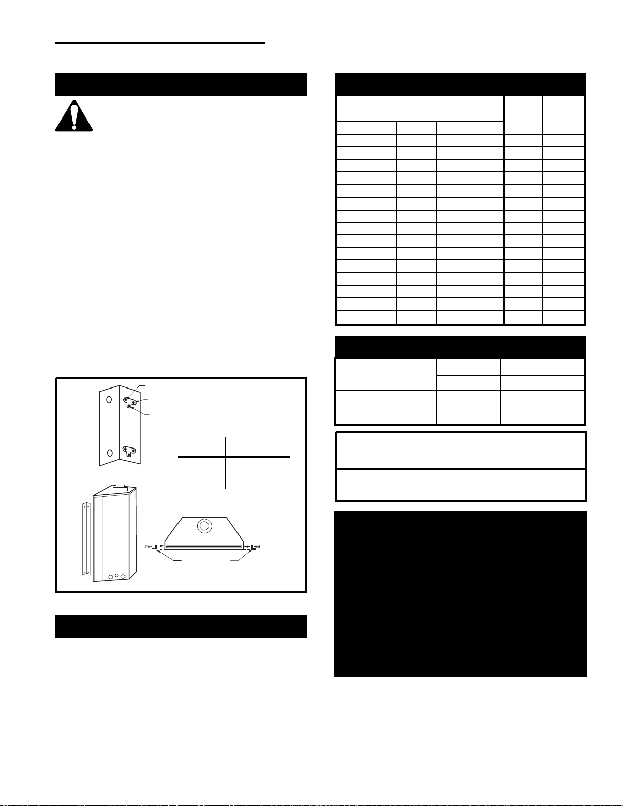
1. Choose the unit location.
2. Place the unit into position and secure it to the floor
with 1¹⁄₂” (38mm) screws or nails. Holes for securing
the unit to floor are located behind the access door
grille on the left and right sides of the unit.
3. Frame in the fireplace with a header across the top.
It is important to allow for the finished wall face
when setting the depth of the frame.
4. Attach the fireplace to the frame using the
adjustable frame drywall strips (located behind the
access door for shipping). Preset the depth to suit
the facing material of the wall. The strips are
adjustable to 1/2” (13mm), 5/8” (16mm) or
3/4” (19mm). (Fig. 5)
5. Screw through the slotted holes in the drywall strip
and into predrilled holes in fireplace side. Measure
from face of fireplace to the face of the drywall strip to
confirm the final depth.
Check the fireplace to make sure it is
leveled and properly positioned.
Framing & Finishing
Noncombustible materials such as brick or tile may be
extended over the edges of the face of the appliance.
DO NOT cover the window frame assembly, any
vent, louvre assembly top or louvre assembly
bottom.
If a Trim Kit is to be installed on the fireplace, the brick
or tile will have to be installed flush with the edges of
the appliance.
Final Finishing
Fig. 5 Adjustable drywall strip (nailing flanges).
C
A
B
Adjustable Drywall Strip
(Nailing Flange)
FP1023
Adjustable
1/2” – 5/8” – 3/4”
Spacing
Screw Drywall
Position Depths
A 1/2” (13mm)
B 5/8” (16mm)
C 3/4” (19mm)
Inlet Minimum 5.5” w.c. 11.0” w.c.
Inlet Maximum 14.0” w.c. 14.0” w.c.
Manifold Pressure 3.5” w.c. 10.0” w.c.
Gas Inlet and Manifold Pressures
Natural LP (Propane)
High Elevations
Input ratings are shown in BTU per hour (BTU/h)
and are certified without deration for elevations
up to 4,500 feet (1,370 m) above sea level.
For elevations above 4,500 feet (1,370 m) in USA,
installations must be in accordance with the
current ANSI Z223.1/NFPA 54 and/or local codes
having jurisdiction.
In Canada, please consult provincial and/or local
authorities having jurisdiction for installations at
elevations above 4,500 feet (1,370 m).
DVRT36/ DVRT36RMH/ DVRT39/ DVRT43
Certified To
ANSI Z21.88-2002/ CSA 2.33-2002
Vented Gas Fireplace Heaters
Max. Min.
Input Input
Model Fuel Gas Control BTU/h BTU/h
DVRT36RN Nat Millivolt 25,000 17,500
DVRT36RP Prop Millivolt 25,000 18,750
DVRT36EN Nat 24V Hi/Lo 25,000 17,500
DVRT36EP Prop 24V Hi/Lo 25,000 18,750
DVRT36RFN Nat Comfort Control 25,000 17,500
DVRT36RFP Prop Comfort Control 25,000 18,750
DVRT36RMH Nat/Prop Millivolt 25,000 17,500
DVRT39RN Nat Millivolt 30,000 21,000
DVRT39RP Prop Millivolt 30,000 22,500
DVRT39EN Nat 24V Hi/Lo 30,000 21,000
DVRT39EP Prop 24V Hi/Lo 30,000 22,500
DVRT43RN Nat Millivolt 33,000 23,100
DVRT43RP Prop Millivolt 33,000 24,750
DVRT43EN Nat 24V Hi/Lo 33,000 23,100
DVRT43EP Prop 24V Hi/Lo 33,000 24,750
Gas Specifications
8
Vermont Castings, Majestic Products DVRT36/39/ 43
10002428
The gas pipeline can be brought in through the side of
the fireplace as well as the bottom. Knockouts are
provided on the bottom behind the valve to allow for the
gas pipe installation and testing of any gas connection.
It is most convenient to bring the gas line in from the
rear right side of the valve as this allows fan installation
or removal without disconnecting the gas line.
The gas line connection can be made with properly
tinned 3/8” copper tubing, 3/8” rigid pipe or an ap-
proved flex connector. Since some municipalities have
additional local codes, it is always best to consult your
local authority and the CSA-B149.1 installation codes.
For USA installations consult the current National Fuel
Gas Code, ANSI Z223.1/NFPA 54.
Gas Line Installation
When purging the gas lines, the front
glass must be removed.
Always check for gas leaks with a mild
soap and water solution applied with a
brush no larger than 1” (25 mm). Never
apply soap and water solution with a
spray bottle. Do not use an open flame
for leak testing.
The fireplace valve must not be
subjected to any test pressures
exceeding 1/2 p.s.i. Isolate or disconnect
this or any other gas appliance control
from the gas line when pressure testing.
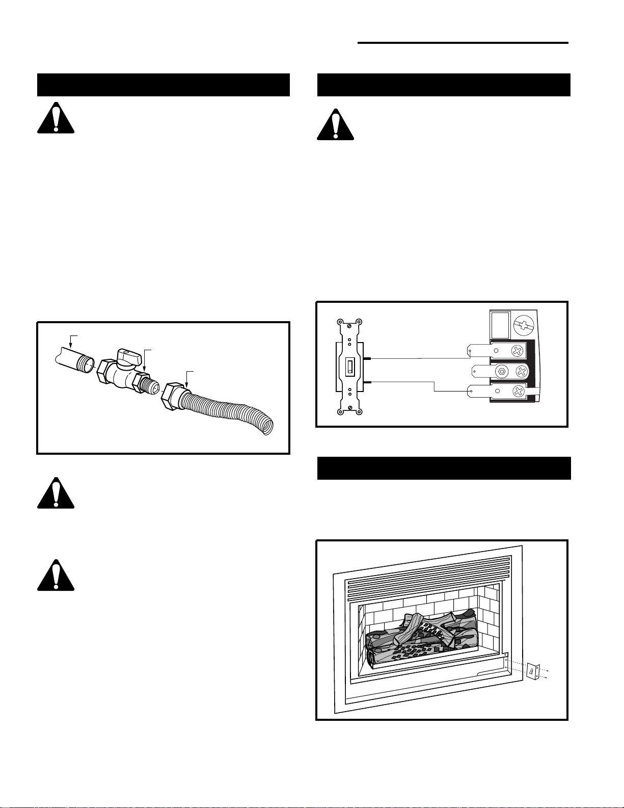
1. Thread the wiring through the electrical knockout
located on either side of the unit. Take care not to
cut the wire or insulation on metal edges. Ensure
the wire is secured and protected from possible
damage. Run one end to the gas control valve and
the other end to the conveniently located wall
switch.
2. Attach the wire to the ON/OFF switch and install the
switch into the receptacle box. Attach the cover
plate to the switch.
3. Connect the wire to the gas control valve. (Fig. 7)
Remote ON/OFF Switch Installation
Do not wire the remote ON/OFF wall
switch for this gas appliance into a 120 V
power supply.
Alternate Switch Location
The remote switch can be installed on either side of the
access door. Mount the switch to the bracket provided
and screw the bracket to either side of the frame, using
the pre-punched holes. (Fig. 8)
TPTH
TH
TP
Remote
ON/OFF
Switch
W584-9
Fig. 7 Remote switch wiring diagram for R models.
The gas control is equipped with a captured screw type
pressure test point; therefore, it is not necessary to
provide a 1/8” test point upstream of the control.
When using copper or flex connector use only ap-
proved fittings. Always provide a union when using
black iron pipe so that the gas line can be easily
disconnected for burner or fan servicing. (Fig. 6) See
the gas specifications for pressure details and ratings.
CFM104
Fig. 8 Alternate switch location.
FP297A
Fig. 6 Typical gas supply installation.
1/2” Gas Supply
1/2” NPT x 1/2” Flare
Shut-Off Valve
3/8” Flex Line
(From Valve)
9
10002428
Vermont Castings, Majestic Products DVRT36/39/ 43
The fireplace, when installed, must be
electrically connected and grounded in
accordance with local codes; or, in the
absence of local codes, with the current
CSA C22.1 Canadian Electrical Code
For USA installations, follow the local
codes and the national electrical code
ANSI/NFPA No. 70.
It is strongly suggested that a licensed
electrician perform the wiring of the
EB-1 Electrical Junction Box.
Ensure that the power to the supply
line has been disconnected before
commencing this procedure.
The EB-1 Electrical junction box is fitted with this
model to provide for easy installation of an optional fan
kit.
To connect the EB-1 box to the house electrical supply
follow the steps below:
1. Unscrew the retaining screw from the EB-1 base
plate (Fig. 9), and remove the EB-1 assembly from
the fireplace.
2. Remove the front cover of the EB-1 box.
3 Remove the plug socket assembly from the EB-1
box.
4. Feed the supply line in from the outside through the
cable clamp. (Fig. 9)
5. Connect black wire of the power supply line to the
brass screw (polarized) of the socket assembly.
6. Connect the white wire of the power line to the
chrome screw of the socket assembly.
7. Connect the ground wire of the supply line to the
green screw of the socket assembly.
8. Refit the socket assembly back into the electrical
box and replace the cover plate. Secure the cable
with the clamp on the outside of the unit to prevent
strain on the connections.
EB-1 Electrical Box
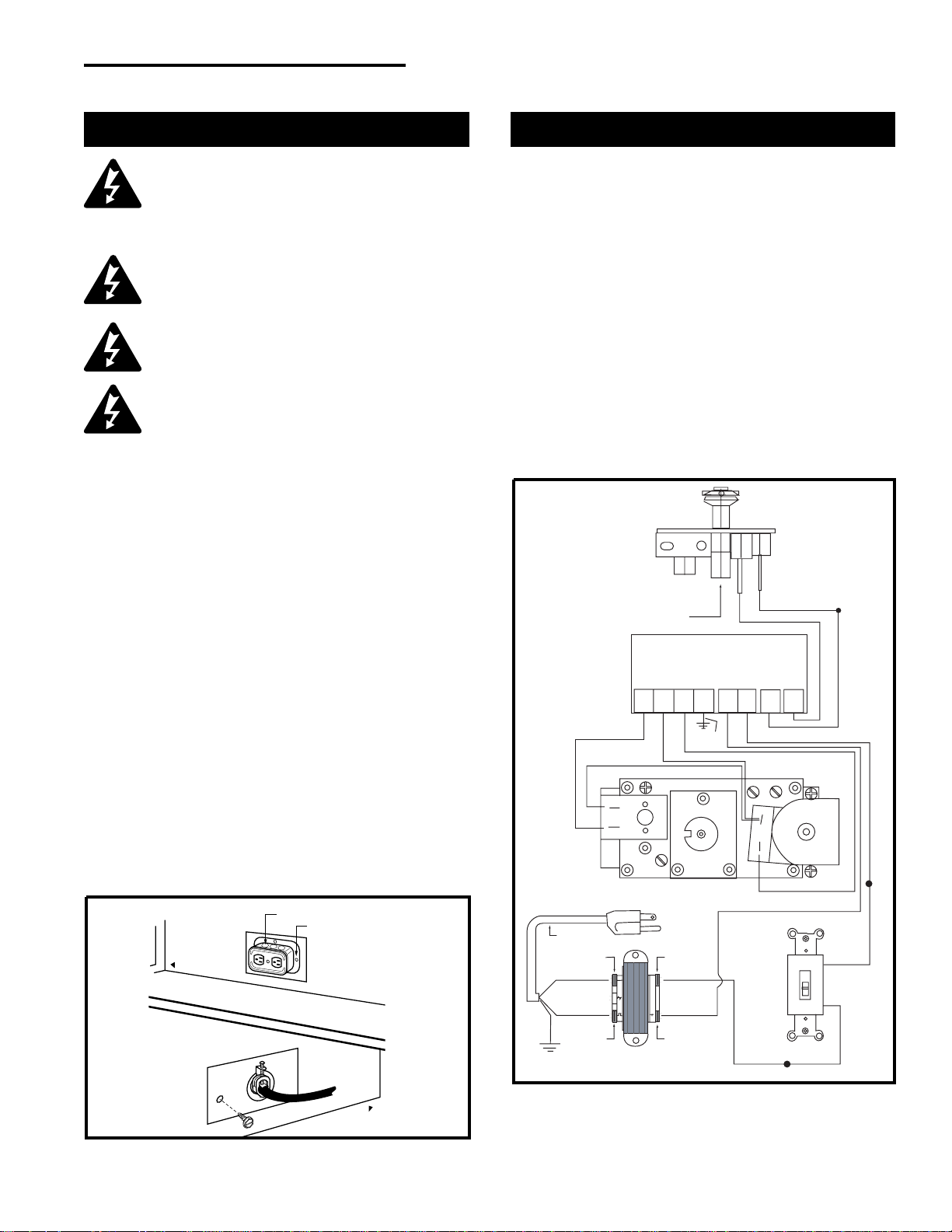
This appliance may be fitted with a Honeywell ignition
module.
Installation of the remote on/off starter switch on
electronic ignition units:
1. Thread the wiring through the holes on the side
panels of the appliance. Take care not to cut the
wire or insulation on metal edges. Route the wire to
a conveniently located receptacle box.
2. Attach the wire to the ON/OFF switch and install the
switch into the receptacle box. (Fig. 10)
3. Connect the White wire from the wall switch to the
Black wire from the transformer, using an approved
wire nut. Connect the Black wire from the wall
switch to the Black wire running from the #6 position
of the ignition module, also using an approved wire
nut.
Electronic Gas Control Valve
PILOT
HONEYWELL IGNITION MODULE
ORANGE
BLUE
BLACK
WHITE
NOVA SIT 822 VALVE
HI
LO
POWER CORD
W/FEMALE SPADE
120 VAC RTN
WHITE
GREEN
BLACK
120 VAC HOT
BLACK
YELLOW
24 VAC RET
40VA TRANSFORMER
24 VAC HOT
BLACK
WHITE
WALL SWITCH
WHITE
OFF
1 2 3 5 6 8 9
MV MV/VP PV GRD 24V SENSE SPARK
24V
ORANGE
RED
GREEN
BLACK
Fig. 10 Honeywell ignition module.
FP1225
Front of Unit
Front of Unit
FP580
Fig. 9 EB-1 receptacle.
Electrical Box
Retaining Screw
Inside
Outside
10
Vermont Castings, Majestic Products DVRT36/39/ 43
10002428
After conversion to top vent
configuration, the 4” (102mm) flue pipe
should be concentric within the 7”
(175mm) outer collar.
Installing the DVRT36RMH
in a Mobile Home
NOTE: Refer to “For Use in Mobile Homes: Model
DVRT36RMH” on Pages 46 and 47.
The insulation pad extends beyond the
opening in the top of the unit. Be sure to
remove all of the insulation material
before completing the conversion.
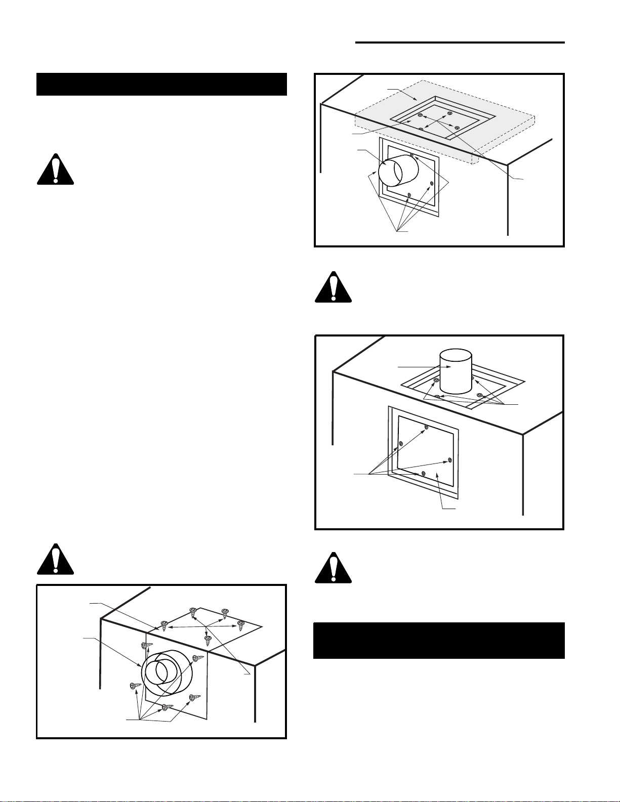
Optional Top Vent Application
The DVRT appliance is shipped as a rear vent unit. If
the installation layout requires the unit to be a top vent
configuration the appliance can be converted by
following the steps below.
When removing and refitting the plates
and adapter, be sure the associated
gaskets are undamaged and refitted as
required.
1. Remove the ten (10) screws securing the outer
collar adapter to the fireplace body. (Fig. 11)
2. Set the collar aside, complete with the gasket.
Do not damage the gasket, as the adapter
and gasket must be refitted.
3. Remove the insulation material (exposed in Step 2)
from the top of the unit. (Fig. 12) This material can
be discarded. However, if the unit is converted back
to rear vent for any reason a new piece of insulation
material approved by Vermont Castings, Majestic
Products must be used for this purpose.
4. Remove the four (4) screws securing the flue cover
plate to the top of the intake box and remove the
cover and gasket. (Fig. 12)
5. Remove the four (4) screws securing the flue pipe
to the back of the intake box and remove the pipe
and gasket. (Fig. 12)
6. Secure the plate and gasket removed in Step 4 over
the flue opening in the back of the intake box.
Ensure the gasket is in place and undamaged.
7. Install the flue pipe and gasket removed in Step 5
over the flue opening in the top of the intake box.
(Fig. 13)
8. Refit the outer collar adapter and gasket to the unit
with the round collar on the top. Secure the adapter
with the ten (10) screws removed in Step 1.
When converting appliance to top vent,
ensure the insulation material referred to
in Step 3 is completely removed.
FP1027
Fig. 12 Remove flue cover, flue pipe and insulation pad.
Insulation
Remove Screws (4)
Flue
Cover
Flue
Pipe
Remove
Screws
(4)
FP1028
Fig. 13 Flue cover and flue pipe location.
Flue Pipe
Replace
Screws
(4)
Flue Cover
Replace
Screws
(4)
FP1030
Fig. 11 Remove screws from outer collar adapter.
Outer Collar
Adapter
Flue
Pipe
Remove
Screws (5)
Rear View
Remove
Screws
(5)

11
10002428
Vermont Castings, Majestic Products DVRT36/39/ 43
General Venting
Your fireplace is approved to be vented either through
the side wall, or vertically through the roof.
NOTE: Only venting components specifically
approved and labeled for this fireplace may be
used.
• Venting terminals shall not be recessed into a wall
or siding.
• Horizontal venting must be installed on a level plane
without any incline or decline.
• There must not be any obstructions such as
bushes, garden sheds, fences, decks, or utility
buildings within 24” (610mm) from the front of the
termination hood.
• Do not locate the termination hood where excessive
snow or ice buildup may occur.
• Be sure to check and clear the vent termination
area after snow falls, to prevent accidental blockage
of venting system.
• When using snow blowers, make sure snow is not
directed toward the vent termination area.
Location of Vent Termination
It is imperative to observe minimum
clearances (shown on the following
page) when locating vent terminations.
12
Vermont Castings, Majestic Products DVRT36/39/ 43
10002428
V
V
V
V
V
V
V
X
X
X
D
E
B
B
B
C
B
M
B
A
J
K
F
L
VENT TERMINATION AIR SUPPLY INLET
AREA WHERE TERMINAL IS NOT PERMITTED
H
I
Fixed
Closed
Fixed
Closed
Operable
Operable
Fixed
Closed
V
B
INSIDE
CORNER DETAIL
V
A
G
V
N
N
V
V
G
G
A
CFM145a
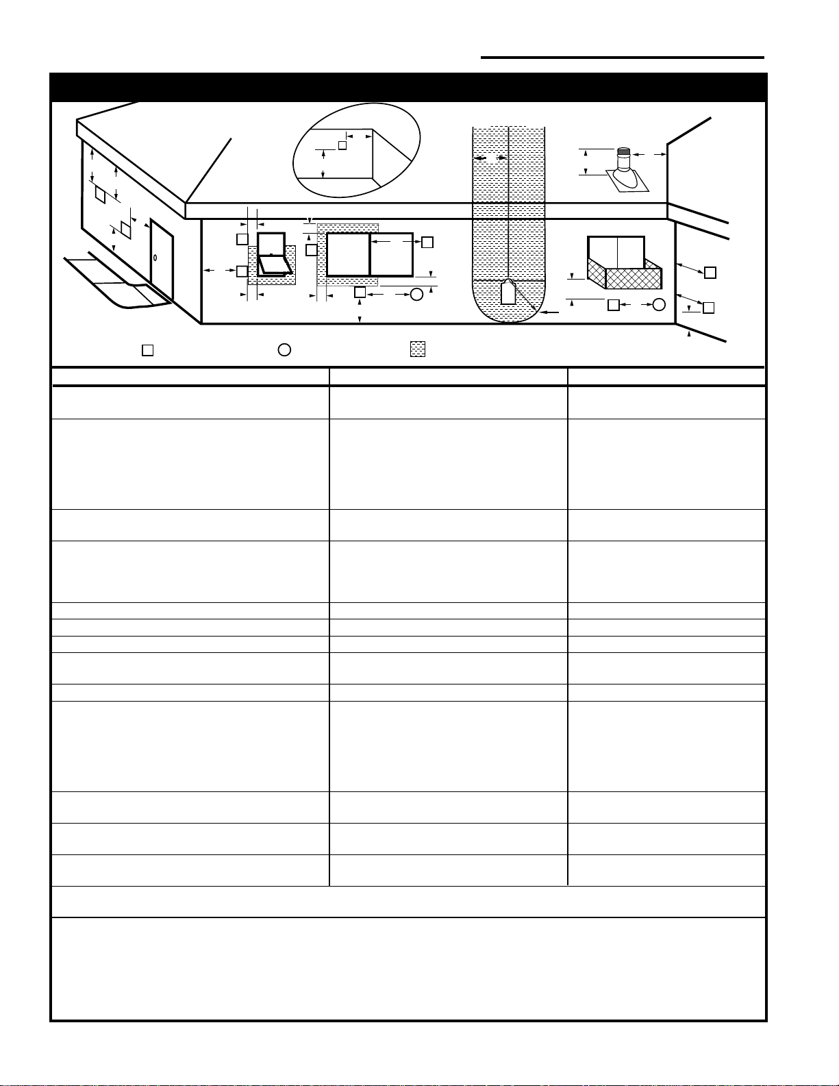
General Venting Information - Termination Location
A = Clearance above grade, veranda, porch, 12” (30cm) 12” (30cm)
deck, or balcony
B = Clearance to window or door that may be 6” (15cm) for appliances 6” (15cm) for appliances
opened < 10,000Btuh (3kW), 12” (30cm) < 10,000 Btuh (3kW), 9”
for appliances > 10,000 Btuh (3kW) and (23cm) for appliances > 10,000
< 100,000 Btuh (30kW), 36” (91cm) Btuh (3kW) and < 50,000 Btuh
for appliances > 100,000 Btuh (30kW) (15kW), 12” (30cm) for
appliances > 50,000 Btuh (15kW)
C = Clearance to permanently closed window 12” (305mm) recommended to 12” (305mm) recommended to
prevent window condensation prevent window condensation
D = Vertical clearance to ventilated soffit located
above the terminal within a horizontal 18” (458mm) 18” (458mm)
distance of 2 feet (610mm) from the center
line of the terminal
E = Clearance to unventilated soffit 12” (305mm) 12” (305mm)
F = Clearance to outside corner see next page see next page
G = Clearance to inside corner (see next page) see next page see next page
H = Clearance to each inside of center line 3’ (91cm) within a height of 15’ 3’ (91cm) within a height of 15’
extended above meter/regulator assembly above the meter/regulator assembly above the meter/regulator assy
I = Clearance to service regulator vent outlet 3’ (91cm) 3’ (91cm)
J = Clearance to nonmechanical air supply inlet 6” (15cm) for appliances < 10,000 6” (15cm) for appliances
to building or the combustion air inlet to any Btuh (3kW), 12” (30cm) for < 10,000 Btuh (3kW), 9”
other appliances appliances > 10,000 Btuh (3kW) and < (23cm) for appliances > 10,000
100,000 Btuh (30kW), 36” (91cm) Btuh (3kW) and < 50,000 Btuh
for appliances > 100,000 Btuh (30kW) (15kW), 12” (30cm) for
appliances > 50,000 Btuh (15kW)
K = Clearance to a mechanical air supply inlet 6’ (1.83m) 3’ (91cm) above if within 10’
(3m) horizontally
L = Clearance above paved sidewalk or paved 7’ (2.13m)† 7’ (2.13m)†
driveway located on public property
M = Clearance under veranda, porch, deck or 12” (30cm)‡ 12” (30cm)‡
balcony
N = Clearance above a roof shall extend a minimum of 24” (610mm) above the highest point when it passes through the roof
surface, and any other obstruction within a horizontal distance of 18” (450mm).
1 In accordance with the current CSA-B149 Installation Codes
2 In accordance with the current ANSI Z223.1/NFPA 54 National Fuel Gas Codes
† A vent shall not terminate directly above a sidewalk or paved driveway which is located between two single family dwellings and
serves both dwellings
‡ only permitted if veranda, porch, deck or balcony is fully open on a minimum 2 sides beneath the floor:
NOTE: 1. Local codes or regulations may require different clearances.
2. The special venting system used on Vermont Castings, Majestic Products Direct Vent Fireplaces are certified as part of the
appliance, with clearances tested and approved by the listing agency.
Canadian Installations
1
US Installations
2
Fig. 14 Vent termination clearances.
13
10002428
Vermont Castings, Majestic Products DVRT36/39/ 43
General Information for Connecting Vent Pipes
Crimped End Pipes
Before joining elbows and pipes, apply a bead of high
temperature sealant to the crimped end of the elbow or
pipe.
Join the pipes using a 2” (51mm) overlap and secure
the joints with three (3) sheet metal screws. (Fig. 16)
Wipe off excess sealant.
Canadian Installations:
The venting system must be installed in accordance
with the current CSA-B149.1 installation code.
USA Installations:
The venting system must conform to local codes and/
or the current National Fuel Code ANSI Z223.1/NFPA
54.
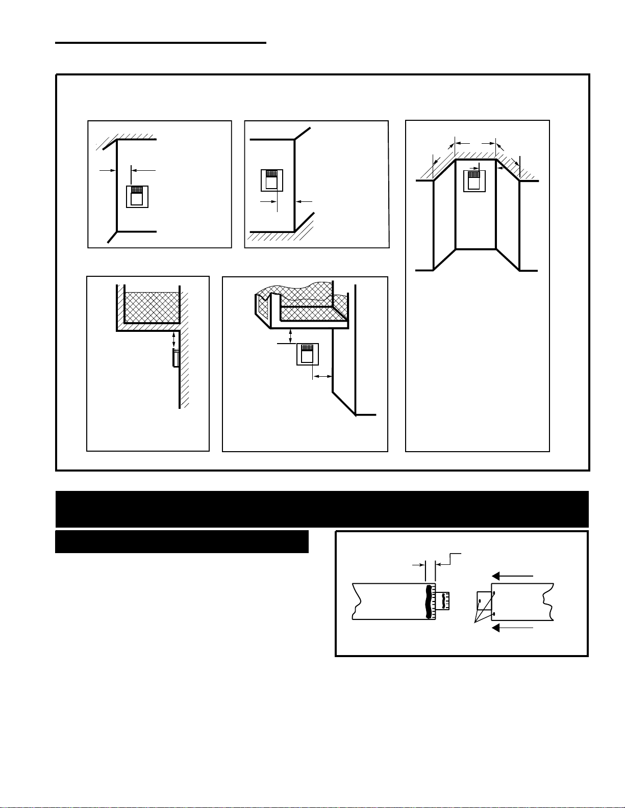
Outside Corner
Inside Corner
Termination Clearances
Termination clearances for buildings with combustible and noncombustible exteriors.
A =
Combustible
6" (152 mm)
Noncombustible
2" (51 mm)
B =
Combustible
6" (152 mm)
Noncombustible
2" (51 mm)
A
Balcony
with no side wall
G =
Combustible
Noncombustible
12" (305 mm)
G
Balcony
with perpendicular side wall
H = 24" (610 mm)
J = 20" (508 mm)
H
J
B
Recessed Location
C = Maximum depth of 48"
(1219mm) for recessed
location.
D = Minimum width for back wall
of a recessed location.
Combustible 38" (965 mm)
Noncombustible 24" (610 mm)
E = Clearance from corner in
recessed location.
Combustible 6" (152 mm)
Noncombustible 2" (50 mm)
C
D
C
E
V
V
Combustible &
Noncombustible
V
V
V
CFM115
Fig. 15 Termination clearances.
1" (25 mm) from
crimped end of pipe
Screw
Holes
CFM175
Fig. 16 Apply a bead of high temperature sealant.
Only venting components manufactured by Vermont
Castings, Majestic Products may be used in Direct
Vent systems.
14
Vermont Castings, Majestic Products DVRT36/39/ 43
10002428
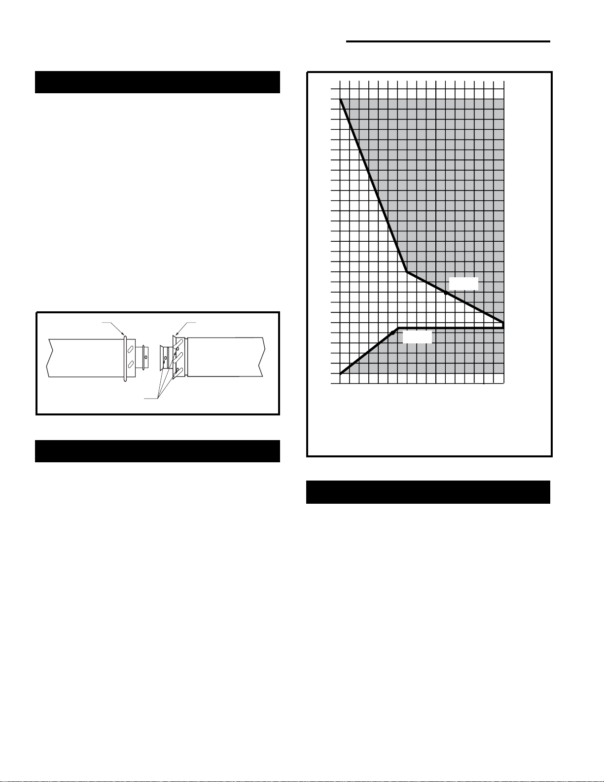
Twist-lock Pipes
When using Vermont Castings, Majestic Products
twist-lock pipe it is not necessary to use sealant on the
joints. The only areas of the venting system that need
to be sealed with high temperature silicone sealant are
the collars on the fireplace and the sliding joint of any
telescopic vent section used in the system.
To join twist-lock pipes together, simply align the beads
of the male end with the grooves of the female end,
twisting the pipe until the flange on the female end
contacts external flange on the male end. It is
recommended that you secure the joints with three (3)
sheet metal screws; however, this is not mandatory
with twist-lock pipe. (Fig. 17)
To make it easier to assemble the joints we suggest
putting a lubricant (Vaseline or similar) on the male
end of the twist-lock pipe prior to assembly.
How to Use the Vent Graph
The Vent Graph should be read in conjunction with the
following vent installation instructions to determine the
relationship between the vertical and horizontal
dimensions of the vent system.
1. Determine the height of the center of the horizontal
vent pipe exiting through the outer wall. Using this
dimension on the Sidewall Vent Graph below, locate
the point intersecting with the slanted graph line.
2. From the point of this intersection, draw a vertical
line to the bottom of the graph.
3. Select the indicated dimension, and position the
fireplace in accordance with same.
Example A:
If the vertical dimension from the floor of the fire-
place is 11’ (3.4m), the horizontal run to the face of
the outer wall must not exceed 14’ (4.3m).
Example B:
If the vertical dimension from the floor of the unit is
7’ (2.14m), the horizontal run to the face of the outer
wall must not exceed 8¹⁄₂’ (2.6m).
Rear Wall Vent Application
When installed as a rear vent unit this appliance may
be vented directly to a termination located on the rear
wall behind the appliance.
• Only Vermont Castings, Majestic Products venting
components are approved to be used in these
applications. See ‘Venting Components’ listed for
different installation requirements.
• The maximum horizontal distance between the rear
of the appliance (or end of the transition elbow in a
corner application) and the outside face of the rear
wall is 20” (508 mm). (Fig. 19)
• Only one 45° elbow is allowed in these installations.
• The minimum clearances between any combustible
material and the vent pipe sections are:
Top 2” (51mm)
Sides 1” (25mm)
Bottom 1” (25mm)
3
4
5
6
7
8
9
10
11
12
13
14
15
16
17
18
19
20
21
22
23
24
25
26
27
28
29
30
3 4 5 6 7 8 9 10 11 12 13 14 15 16 17 18 19 20
eg: A
eg: B
Horizontal dimension from the outside face of
the wall to the center of the fireplace vent flange
Vertical dimension from the floor of the unit
to the center of the horizontal vent pipe
Sidewall Vent Graph showing the relationship between vertical
and horizontal dimensions for a Direct Vent flue system.
CFM102
Fig. 18 Sidewall Vent Graph (dimensions in ft.).
Male End
Female End
Screw Holes
TWL100
Fig. 17 Twist-lock pipe joints.
15
10002428
Vermont Castings, Majestic Products DVRT36/39/ 43
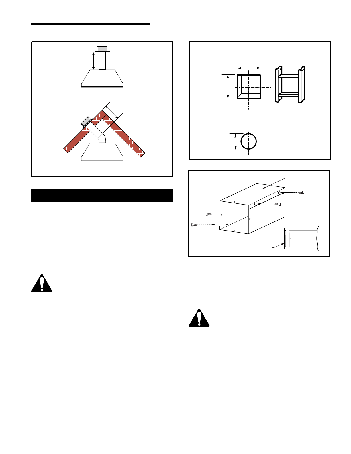
Rear Wall Vent Installation
Step 1
Locate and cut the vent opening in the wall.
For combustible walls, first frame in opening. (Fig. 20)
Combustible Walls: Cut a 10³⁄₈”H x 9³⁄₈”W
(265 x 240mm) hole through the exterior wall and
frame as shown.
Noncombustible Walls: Hole opening should be
7¹⁄₂” (190mm) in diameter.
Zero clearance sleeve is required only
for combustible walls.
Step 2
Measure wall thickness and cut zero clearance sleeve
parts to proper length (maximum 12” / 305mm). As-
semble sleeve to its maximum opening (10³⁄₈” x
9³⁄₈”)(265 x 240mm), and attach to firestop with #8
sheet metal screws (supplied). Install firestop assem-
bly. (Fig. 21)
Step 3
Measure the horizontal length requirement for the
venting including a 2” (51mm) overlap; i.e., from the
elbow to the outside wall face plus 2” (51mm).
(Fig. 19)
It is critical that there is no downward
slope away from the appliance when
connecting the vent or elbow.
Step 4
Install the 4” (102mm) vent to the appliance collar and
secure with 3 sheet metal screws. Install the 7”
(175mm) vent pipe to the appliance collar and secure
with 3 sheet metal screws. If a 45° elbow is being
Step 5
Guide the venting through the vent hole as you place
the appliance in its installed position. Guide the 4”
(102mm) and 7” (175mm) collars of the vent
termination into the outer ends of the venting. Do not
force the termination. If the vent pipes do not align with
the termination, remove and realign the venting at the
appliance flue collars. (Fig. 22) Attach the termination
to the wall as outlined in the instruction sheet supplied
with the termination.
FP1188
Fig. 19 Rear vent application, maximum horizontal distance.
Max. 20"
(508 mm)
Top view flat installation
Max. 20"
(508 mm)
Top view corner installation
used, attach the elbow to the appliance with sealant in
the same manner then attach the venting to the elbow.
It is not necessary to seal the 45° elbow to the starter
pipe or termination in the straight out and 45° installa-
tion in Figure 19.
(240mm)
9³⁄₈"
10³⁄₈"
(254mm)
7¹⁄₂"
(190mm)
Vent Opening — Combustible Wall
Vent Opening — Noncombustible Wall
(framing detail)
CFM116
Fig. 20 Vent opening, side wall.
Fig. 21 Adjustable zero clearance sleeve
CFM135a
Maximum Length
12” (305mm)
#8 Screws (2)
Side View
Firestop
#8 Screws (2)
 Loading...