

Page 1
INSTALLER/CONSUMER
SAFETY INFORMATION
PLEASE READ THIS MANUAL
BEFORE INSTALLING AND
USING APPLIANCE
WARNING!
IF THE INFORMATION IN THIS
MANUAL IS NOT FOLLOWED
EXACTLY, A FIRE OR
EXPLOSION MAY RESULT
CAUSING PROPERTY
DAMAGE, PERSONAL INJURY
OR LOSS OF LIFE.
FOR YOUR SAFETY
Installation and service must
be performed by a qualified
installer, service agency or
the gas supplier.
Freestanding Direct Vent
Fireplace
Models: RFSDV24, RFSDV34
WHAT TO DO IF YOU SMELL GAS:
• Do not try to light any appliance.
• Do not touch any electric switch;
do not use any phone in your
building.
• Immediately call your gas
supplier from your neighbor’s
phone. Follow the gas suppliers
instructions.
• If you cannot reach your gas
supplier call the fire department.
DO NOT STORE
OR USE GASOLINE OR
OTHER FLAMMABLE VAPORS
AND LIQUIDS IN THE VICINITY
OF THIS OR ANY OTHER
APPLIANCE.
Installation Instructions and
Homeowner’s Manual
INSTALLER: Leave this manual with the appliance.
CONSUMER: Retain this manual for future reference.
10003550 6/08 Rev. 6
Page 2

RFSDV24/34 Freestanding Direct Vent Gas Fireplace
Table of Contents
PLEASE READ THE INSTALLATION & OPERATING INSTRUCTIONS BEFORE USING THIS APPLIANCE.
Thank you and congratulations on your purchase of a Vermont Castings fireplace.
IMPORTANT: Read all instructions and warnings carefully before starting installation. Failure to follow these
instructions may result in a possible fire hazard and will void the warranty.
Installation & Operating Instructions
General Information, Warnings, Cautions ...........................................................................3
Requirements for the Commonwealth of Massachusetts ....................................................4
Fireplace Dimensions ..........................................................................................................5
Locating Your Fireplace .......................................................................................................6
Clearance to Combustibles .................................................................................................6
High Elevations ...................................................................................................................6
Gas Inlet and Manifold Pressures .......................................................................................6
Gas Specifications ...............................................................................................................6
Preparation ..........................................................................................................................6
Gas Line Installation ............................................................................................................6
Remote Switch Installation .................................................................................................. 7
General Venting Information
General Venting Information-Termination Location ............................................................8
General Information on Assembling Vent Pipes .................................................................. 9
How to Use the Vent Graph...................................... .........................................................10
Vertical Sidewall Applications & Installation ......................................................................10
Below Grade Installations.. ................................................................................................ 13
Vertical Through-the-Roof Applications & Installations ...................................................... 14
Venting Components .........................................................................................................16
Operating Instructions
Glass Information ..............................................................................................................17
Window Frame Assembly Removal ................................................................................... 17
Glass Cleaning .................................................................................................................. 17
Log Set and Lava Rock Material Installation ..................................................................... 17
Flame & Temperature Adjustment .....................................................................................19
Flame Characteristics ........................................................................................................ 19
Lighting & Operating Instructions ......................................................................................20
Instructions for RF Comfort Control Valve ......................................................................... 21
Troubleshooting ................................................................................................................. 25
Maintenance
Cleaning the Standing Pilot Control System .....................................................................26
Replacement Parts ...................................................................................................................... 27
Installation in Mobile Homes ......................................................................................................30
Optional Accessories
Fan Kits ............................................................................................................................. 31
Optional Gold Trim Kit ....................................................................................................... 32
Optional Brass Trim Kit ......................................................................................................32
Remote Control Units ........................................................................................................ 32
Warranty .......................................................................................................................................35
Energuide ......................................................................................................................................36
2
10003550
Page 3
Installation & Operating Instructions
�
This gas fireplace should be installed by a qualified installer in
accordance with local building codes and with current CSAB149.1 Installation codes for Gas Burning Appliances and
Equipment. If the unit is being installed in a mobile home, the
installation should comply with the current CAN/USA Z240.4
code. For USA Installations follow local codes and/or the
current National Fuel Gas Code. ANSI Z223.1/NFPA 54.
FOR SAFE INSTALLATION AND OPERATION PLEASE NOTE
THE FOLLOWING:
1 . This fireplace gives off high temperatures and should be
located out of high traffic areas and away from furniture and
draperies.
2. Children and adults should be alerted to the hazards of the
high surface temperatures of this fireplace and should stay
away to avoid burns or ignition of clothing.
3. CAUTION: Due to high glass surface temperature chil-
dren should be carefully supervised when in the same
room as fireplace.
RFSDV24/34 Freestanding Direct Vent Gas Fireplace
13. This fireplace must not be connected to a chimney flue
serving a separate solid fuel burning fireplace.
14. When the fireplace is not in use it is recommended that the
gas control valve be left in the OFF position.
RFSDV24 / RFSDV34
Certified To
ANSI Z21.88-2005 / CSA 2.33-2005
Vented Gas Fireplace Heaters
This appliance may be installed in an aftermarket
permanently located, manufactured home or mobile
home, where not prohibited by local codes.
This appliance is only for use with the type of gas
indicated on the rating plate. This appliance is not
convertible for use with other gases, unless a certified
kit is used.
Model RFSDV34RMH can be installed in manufactured
(mobile) homes by OEM.
4. Under no circumstances should this fireplace be modified.
Parts removed for servicing should be replaced prior to
operating this fireplace again.
5. Installation and any repairs to this fireplace must be per
formed by a qualified installer, service agency or gas sup
plier. A professional service person should be contacted to
inspect the fireplace annually. More frequent cleaning may
be required due to excess lint and dust from carpeting, bedding material, etc.
6. Control compartments, burners and air passages in this fire
place should be kept clean and free of dust and lint. Make
sure that the gas valve and pilot light are turned off before
you attempt to clean this fireplace.
7. The venting system (chimney) of this fireplace should be
checked at least once a year and if needed your venting
system should be cleaned.
8. Keep the area around your fireplace clear of combustible
materials, gasoline and other flammable vapour and liquids.
This fireplace should not be used as a dry-ing rack for clothing, nor should Christmas stockings or decorations be hung
on or around the fireplace.
9. Under no circumstances should any solid fuels (wood, coal,
paper or cardboard etc.) be used in this fireplace.
10. The flow of combustion and ventilation air must not be ob
structed in any way.
11. When the fireplace is installed directly on carpeting, vinyl tile
or any combustible material other than wood, this fireplace
must be installed on a metal or wood panel extending the
full width and depth of the fireplace.
12. This fireplace requires adequate ventilation and combustion
10003550
air to operate properly.
-
IMPORTANT:
PLEASE REVIEW THE FOLLOWING CAREFULLY
Remove any plastic from from parts before turning the
fireplace ON.
It is normal for fireplaces fabricated of steel to give off
some expansion and/or contraction noises during the
start up or cool down cycle. Similar noises are found
with your furnace heat exchanger or car engine.
-
It is not unusual for your gas fireplace to give off some
odor the first time it is burned. This is due to the curing
of the paint and any undetected oil from the manufacturing process.
Please ensure that your room is well ventilated-open
-
all windows.
It is recommended that you burn your fireplace for at least
ten (10) hours the first time you use it. If the optional fan
kit has been installed, place the fan switch in the “OFF”
position during this time.
Proposition 65 Warning: Fuels used in gas, woodburning or oil fired appliances, and the products of combustion
of such fuels, contain chemicals known to the State of
California to cause cancer, birth defects and other reproductive harm.
-
California Health & Safety Code Sec. 25249.6
3
Page 4

RFSDV24/34 Freestanding Direct Vent Gas Fireplace
Installation & Operating Instructions
Requirements for the Commonwealth of
Massachusetts
All gas fitting and installation of this heater shall only be
done by a licensed gas fitter or licensed plumber.
For all side wall horizontally vented gas fueled
equipment installed in every dwelling, building or
structure used in whole or in part for residential
purposes, including those owned or operated by the
Commonwealth and where the side wall exhaust vent
termination is less than seven (7) feet above finished
grade in the area of the venting, including but not limited
to decks and porches, the following requirements shall
be satisfied:
Installation of Carbon Monoxide Detectors
At the time of installation of the side wall horizontal
vented gas fueled equipment, the installing plumber
or gas fitter shall observe that a hard wired carbon
monoxide detector with an alarm is installed on each
additional level of the dwelling, building or structure
served by the side wall horizontally vented gas fueled
equipment. It shall be the responsibility of the property
owner to secure the services of qualified licensed
professionals for the installation of hard wired carbon
monoxide detectors.
In the event that the side wall horizontally vented gas
fueled equipment is installed in a crawl space or an
attic, the hard wired carbon monoxide detector with
alarm and battery back-up may be installed on the next
adjacent floor level.
In the event that the requirements of this subdivision
can not be met at the time of completion of installation,
the owner shall have a period of thirty (30) days
to comply with the above requirements; provided,
however, that during said thirty (30) day period, a
battery operated carbon monoxide detector with an
alarm shall be installed.
Approved Carbon Monoxide Detectors
Each carbon monoxide detector as required in
accordance with the above provisions shall comply with
NFPA 720 and ANSI/UL 2034 listed and IAS certified.
Signage
A metal or plastic identification plate shall be
permanently mounted to the exterior of the building at
a minimum height of eight (8) feet above grade directly
in line with the exhaust vent terminal for the horizontally
vented gas fueled heating appliance or equipment. The
sign shall read, in print size no less than one-half (1/2)
inch in size, “GAS VENT DIRECTLY BELOW, KEEP
CLEAR OF ALL OBSTRUCTIONS”.
4
Inspection
The state or local gas inspector of the side wall
horizontally vented gas fueled equipment shall not
approve the installation unless, upon inspection, the
inspector observes carbon monoxide detectors and
signage installed in accordance with the provisions of
248 CMR 5.08(2)(a)1 through 4.
Exemptions
The following equipment is exempt from 248 CMR
5.08(2)(a)1 through 4:
• The equipment listed in Chapter 10 entitled
“Equipment Not Required To Be Vented” in the most
current edition of NFPA 54 as adopted by the Board;
and
• Product Approved side wall horizontally vented gas
fueled equipment installed in a room or structure
separate from the dwelling, building or structure
used in whole or in part for residential purposes.
MANUFACTURER REQUIREMENTS
Gas Equipment Venting System Provided
When the manufacturer of Product Approved side
wall horizontally vented gas equipment provides a
venting system design or venting system components
with the equipment, the instructions provided by the
manufacturer for installation of the equipment and the
venting system shall include:
• Detailed instructions for the installation of the venting
system design or the venting system components;
and
• A complete parts list for the venting system design or
venting system.
Gas Equipment Venting System NOT Provided
When the manufacturer of a Product Approved side
wall horizontally vented gas fueled equipment does
not provide the parts for venting the flue gases, but
identifies “special venting systems”, the following
requirements shall be satisfied by the manufacturer:
• The referenced “special venting system” instructions
shall be included with the appliance or equipment
installation instructions; and
• The “special venting systems” shall be Product
Approved by the Board, and the instructions for
that system shall include a parts list and detailed
installation instructions.
A copy of all installation instructions for all Product
Approved side wall horizontally vented gas fueled
equipment, all venting instructions, all parts lists
for venting instructions, and/or all venting design
instructions shall remain with the appliance or
equipment at the completion of the installation.
10003550
Page 5
RFSDV24/34 Freestanding Direct Vent Gas Fireplace
A
D
I
H
B
K
J
G
F
E
C
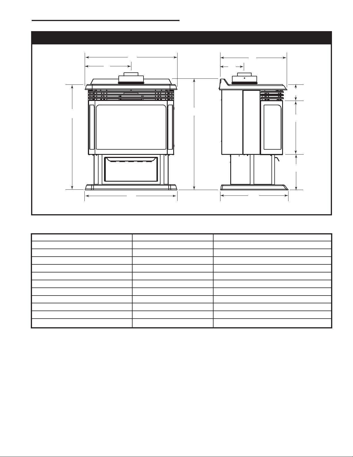
Fireplace Dimensions
Fig. 1 Fireplace specifications and framing dimensions.
Ref. RFSDV24 RFSDV34
A 23” (584 mm) 26
B 28
C 16
D 27
E 9
F 13
G 4” (102 mm) 4
H 23” (584 mm) 26
I 11
J 16
K 6” (152 mm) 6
³⁄₄” (730 mm) 31¹⁄₂” (800 mm)
⁵⁄₈” (422 mm) 19³⁄₈” (492 mm)
³⁄₈” (695 mm) 30” (762 mm)
¹⁄₂” (241 mm) 10” (254 mm)
⁷⁄₈” (352 mm) 15¹⁄₂” (394 mm)
¹⁄₂” (292 mm) 13¹⁄₈” (333 mm)
⁵⁄₈” (422 mm) 19¹⁄₂” (495 mm)
¹⁄₄” (667 mm)
¹⁄₂” (114 mm)
¹⁄₄” (667 mm)
³⁄₈” (162 mm)
10003550
5
Page 6
RFSDV24/34 Freestanding Direct Vent Gas Fireplace
12” (305 mm)
A
12”
(305 mm)
B
E
C
D
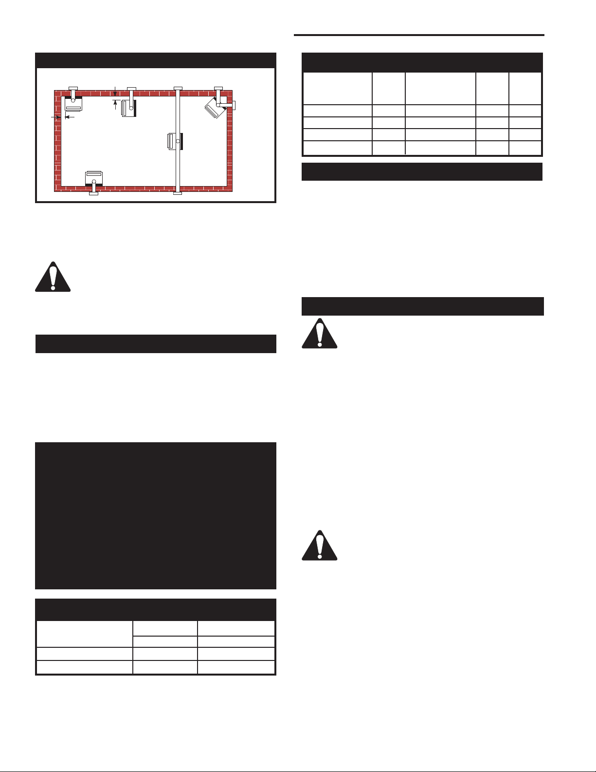
Locating Your Fireplace
FP1620
Fig. 2 Locate gas fireplace.
A) Flat on wall* B) Room Divider* C) Island
D) Cross Corner E) Flat on wall corner
Note (Fig. 2): *(A) and (B) must maintain a 12” (305 mm)
clearance between the wall and side glass of fireplace.
There is a minimum vertical rise required
for the venting, which varies depending on
the application. The maximum horizontal
run also has restrictions. Before starting
the installation, become familiar with venting instructions starting on Page 9.
Clearance to Combustibles
Gas Specifications
Max. Min.
Input Input
Model Fuel Gas Control BTU/h BTU/h
RFSDV24RN Nat Millivolt Hi/Lo 20,000 14,000
RFSDV24RP Prop Millivolt Hi/Lo 20,000 15,000
RFSDV34RFN Nat Comfort Control 30,000 21,000
RFSDV34RFP Prop Comfort Control 30,000 22,500
Preparation
The use of wallpaper adjacent to this fireplace is not
recommended, as the high heat given off by this fireplace may adversely affect the binders in the adhesive
used to apply the wallpaper.
Before beginning, remove the window frame assembly
from the fireplace. Also check to make sure there is not
hidden damage to the fireplace. Take a minute and plan
out the gas, vent and electrical supply. Refer to Window
Frame Assembly Removal Section.
Gas Line Installation
When purging gas line, the front window
frame assembly must be removed.
Top of Unit to Ceiling ............................... 36” (914 mm)
Appliance
Back ........................................................
Side ...................................................
Floor ........................................................
Corner .............................
0” (0 mm) to Back Edges
Vent Pipe ...............................................
0” (0 mm)
12” (305 mm)
0” (0 mm)
1” (25 mm)
High Elevations
Input ratings are shown in BTU per hour and are
certified without deration for elevations up to
4,500 feet (1,370 m) above sea level.
For elevations above 4,500 feet (1,370 m) in USA,
installations must be in accordance with the current ANSI Z223.1/NFPA 54 and/or local codes having jurisdiction.
In Canada, please consult provincial and/or local
authorities having jurisdiction for installations at
elevations above 4,500 feet (1,370 m).
Gas Inlet and Manifold Pressures
Natural LP (Propane)
Inlet Minimum 5.5” w.c. 11.0” w.c.
Inlet Maximum 14.0” w.c. 14.0” w.c.
Manifold Pressure 3.5” w.c. 10.0” w.c.
The gas pipeline can be brought in through the rear
of the fireplace as well as the bottom. Knockouts are
provided on the bottom behind the valve to allow for the
gas pipe installation and testing of any gas connection.
It is most convenient to bring the gas line in from the
rear right side of the valve as this allows fan installation
or removal without disconnecting the gas line.
The gas line connection can be made with properly
tinned 3/8” copper tubing, 3/8” rigid pipe or an approved flex connector. Since some municipalities have
additional local codes, it is always best to consult your
local authority and the National Fuel Gas Code, ANSI
Z223.1/NFPA 54 in the USA or the CSA-B149.1 installation codes.
Always check for gas leaks with a mild
soap and water solution. Do not use an
open flame for leak testing.
The gas control is equipped with a captured
screw type pressure test point, therefore it is not necessary to provide a 1/8” test point up stream of the control.
When using copper or flex connector use only approved
fittings. Always provide a union when using black iron
pipe so that the gas line can be easily disconnected for
burner or fan servicing . See gas specifications for pressure details and ratings.
The fireplace valve must not be subjected to any test
pressures exceeding 1/2 psi. Isolate or disconnect this
or any other gas appliance control from the gas line
when pressure testing.
6
10003550
Page 7
1/2” Gas Supply
P
I
L
O
T
TPTH
TP
TH
PILOT
ADJ
TH
TP
TP
TH
1/2” x 3/8” Reducer
3/8” Nipple
RFSDV24/34 Freestanding Direct Vent Gas Fireplace
Screw
ON/OFF Switch
Assembly
(through existing
hole)
Screw
3/8” Union
CFM106
3/8” Nipple
3/8” x 3/8”
Shut-Off Valve
3/8” Nipple
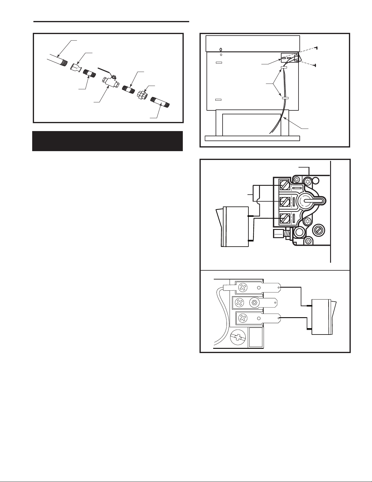
Fig. 3 Typical gas line connection.
Installation of Remote Switch
for RN/RP Gas Valve
NOTES: The remote ON/OFF switch cannot be fitted to units using the Honeywell Radio Frequency
control valve.
If the fireplace has been fitted with the Radio
Frequency Control Valve, the ON/OFF function is
controlled by the remote handset. (Refer to the addendum or instructions packaged with the remote
handset.)
Install the ON/OFF switch assembly on either the rear
right or rear left side of the fireplace.
1. Remove the screw at the back of the cabinet top
either on the left or the right side of the fireplace.
2. Position switch assembly onto the back of the fireplace, then fasten two (2) screws as shown in Figure
3.
3. Attach wiring under the clips on the rear casing (Fig.
4) and install wiring through the rear opening of the
fireplace before connecting to the valve as shown in
Figure 5.
Clips
FP1621
Fig. 4 Attach wiring under clips on rear casing.
Valve
SIT Valve
Thermopile
ON/OFF Switch or
Millivolt Thermostat
RN/RP Valve
Wiring for
Millivolt Gas
Valves
FP1622
10003550
FP1494
Fig. 5 Install wiring to switch before connecting to valve.
7
Page 8
RFSDV24/34 Freestanding Direct Vent Gas Fireplace
V
V
V
V
V
V
V
X
X
X
D
E
B
B
B
C
B
M
B
A
J
K
F
L
VENT TERMINATION AIR SUPPLY INLET
AREA WHERE TERMINAL IS NOT PERMITTED
H
I
Operable
Operable
Fixed
Closed
V
B
INSIDE
CORNER DETAIL
V
A
G
N
N
CFM145a
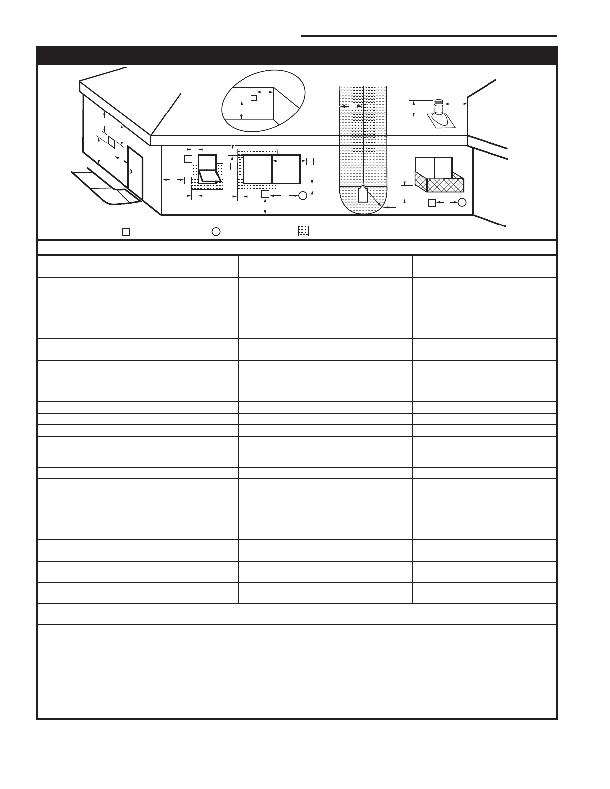
General Venting Information - Termination Location
Canadian Installations1 US Installations
2
A = Clearance above grade, veranda, porch, 12” (30cm) 12” (30cm)
deck, or balcony
B = Clearance to window or door that may be 6” (15cm) for appliances 6” (15cm) for appliances
opened < 10,000Btuh (3kW), 12” (30cm) < 10,000 Btuh (3kW), 9”
for appliances > 10,000 Btuh (3kW) and (23cm) for appliances > 10,000
< 100,000 Btuh (30kW), 36” (91cm) Btuh (3kW) and < 50,000 Btuh
for appliances > 100,000 Btuh (30kW) (15kW), 12” (30cm) for
appliances > 50,000 Btuh (15kW)
C = Clearance to permanently closed window 12” (305mm) recommended to 12” (305mm) recommended to
prevent window condensation prevent window condensation
D = Vertical clearance to ventilated soffit located
above the terminal within a horizontal 18” (458mm) 18” (458mm)
distance of 2’ (610mm) from the center
line of the terminal
E = Clearance to unventilated soffit 12” (305mm) 12” (305mm)
F = Clearance to outside corner see next page see next page
G = Clearance to inside corner (see next page) see next page see next page
H = Clearance to each inside of center line 3’ (91cm) within a height of 15’ (5m) 3’ (91cm) within a height of 15’
extended above meter/regulator assembly above the meter/regulator assembly (5m) above the meter/regulator
assy
I = Clearance to service regulator vent outlet 3’ (91cm) 3’ (91cm)
J = Clearance to nonmechanical air supply inlet 6” (15cm) for appliances < 10,000 6” (15cm) for appliances
to building or the combustion air inlet to any Btuh (3kW), 12” (30cm) for < 10,000 Btuh (3kW), 9”
other appliances appliances > 10,000 Btuh (3kW) and (23cm) for appliances > 10,000
< 100,000 Btuh (30kW), 36” (91cm) Btuh (3kW) and < 50,000 Btuh
for appliances > 100,000 Btuh (30kW) (15kW), 12” (30cm) for
appliances > 50,000 Btuh (15kW)
K = Clearance to a mechanical air supply inlet 6’ (1.83m) 3’ (91cm) above if within 10
feet (3m) horizontally
L = Clearance above paved sidewalk or paved 7’ (2.13m)† 7’ (2.13m)†
driveway located on public property
M = Clearance under veranda, porch, deck or 12” (30cm)‡ 12” (30cm)‡
balcony
N = Clearance above a roof shall extend a minimum of 24” (610mm) above the highest point when it passes through the roof
surface, and any other obstruction within a horizontal distance of 18” (450mm).
1 In accordance with the current CSA-B149 Installation Codes
2 In accordance with the current ANSI Z223.1/NFPA 54 National Fuel Gas Codes
† A vent shall not terminate directly above a sidewalk or paved driveway which is located between two single family dwellings and
serves both dwellings
‡ only permitted if veranda, porch, deck or balcony is fully open on a minimum 2 sides beneath the floor:
NOTE: 1. Local codes or regulations may require different clearances.
2. The special venting system used on Direct Vent Fireplaces are certified as part of the appliance, with clearances tested and
approved by the listing agency.
3. CFM Corporation assumes no responsibility for the improper performance of the appliance when the venting system does not
meet these requirements.
Fig. 6 Termination location requirements.
8
10003550
Page 9
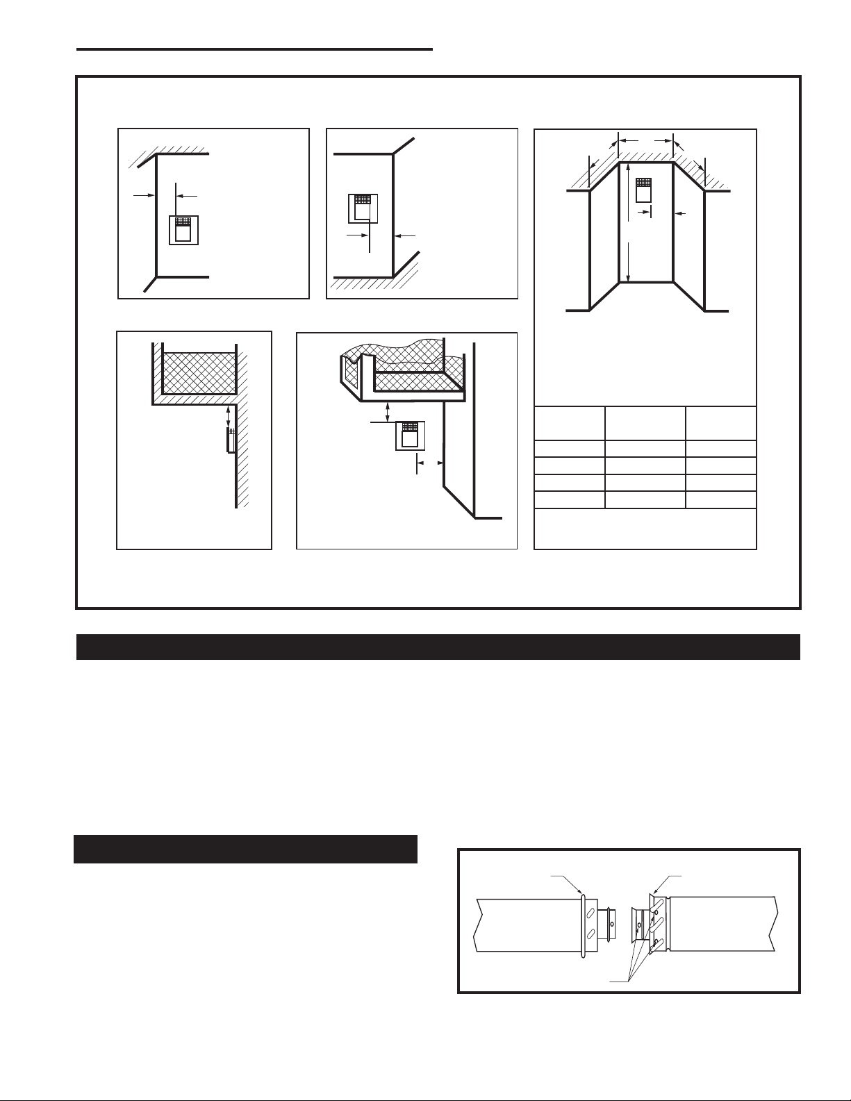
Outside Corner
Inside Corner
Termination Clearances
Termination clearances for buildings with combustible and noncombustible exteriors.
G =
Combustible
6" (152 mm)
Noncombustible
2" (51 mm)
F =
Combustible
6" (152 mm)
Noncombustible
2" (51 mm)
G
Balcony with no side wall
M =
Combustible &
Noncombustible
12" (305 mm)
M
Balcony with perpendicular side wall
M = 24" (610 mm)
P = 20” (508 mm)
M
F
Alcove Applications*
C
D
C
E
V
V
Combustible &
Noncombustible
V
V
V
E = Min. 6” (152 mm) for
non-vinyl sidewalls
Min. 12” (305 mm) for
vinyl sidewalls
O = 8’ (2.4 m) Min.
O
P
*NOTE: Termination in an alcove space (spaces open only on one side and with an overhang) is permitted with the dimensions
specified for vinyl or non-vinyl siding and soffits. 1. There must be a 3’ (914 mm) minimum between termination caps. 2. All
mechanical air intakes within 10’ (1 m) of a termination cap must be a minimum of 3’ (914 mm) below the termination cap. 3. All
gravity air intakes within 3’ (914 mm) of a termination cap must be a minimum of 1’ (305 mm) below the termination cap.
Fig. 6a Termination clearances.
Canadian Installations:
General Information on Assembling Vent Pipes
The venting system must be installed in accordance
with the current CSA-B149 .1 installation code.
USA Installations:
The venting system must conform with local codes and/
or the current National Fuel Gas code ANSI Z223.1/
NFPA 54.
Only venting components manufactured by CFM Corporation can be used in Direct Vent systems.
Twist Lock Pipes
When using CFM Corporation twist-lock pipe it is not
necessary to use sealant on the joints. The only areas
of the venting system that need to be sealed with high
temperature silicone sealant are the collars on the
fireplace and termination, and the sliding joint of any
telescopic vent section used in the system.
10003550
RFSDV24/34 Freestanding Direct Vent Gas Fireplace
No.
of Caps D
1 3’ (.9 mm) 2 x D
2 6’ (1.8 m) 1 x D
3 9’ (2.7 m) 2/3 x D
4 12’ (3.7 m) 1/2 x D
D
= # of Termination caps x 3
Min.
C
= (2 / # termination caps) x D
Max.
To join the twist lock pipes together, simply align the
beads of the male end with the grooves of the female
end, then while bringing the ends together, twist the
pipe until the flange on the female end contacts the
external flange on the male end. It is recommended that
you secure the joints with three (3) sheet metal screws,
however this is not mandatory with twist lock pipe.
To make it easier to assemble the joints we suggest
putting a lubricant (Vaseline or similar) on the male end
of the twist lock pipe prior to assembly.
Male End
Screw Holes
Fig. 7 Twist-lock pipe joints.
C
Min.
Max.
Actual
Actual
Actual
Actual
Actual
Female End
584-15
TWL100
9
Page 10
RFSDV24/34 Freestanding Direct Vent Gas Fireplace
3
4
5
6
7
8
9
10
11
12
13
14
15
16
17
18
19
20
21
22
23
24
25
26
27
28
29
30
3 4 5 6 7 8 9 10 11 12 13 14 15 16 17 18 19 20
Example: A
Example: B
36”
(914 mm)
x
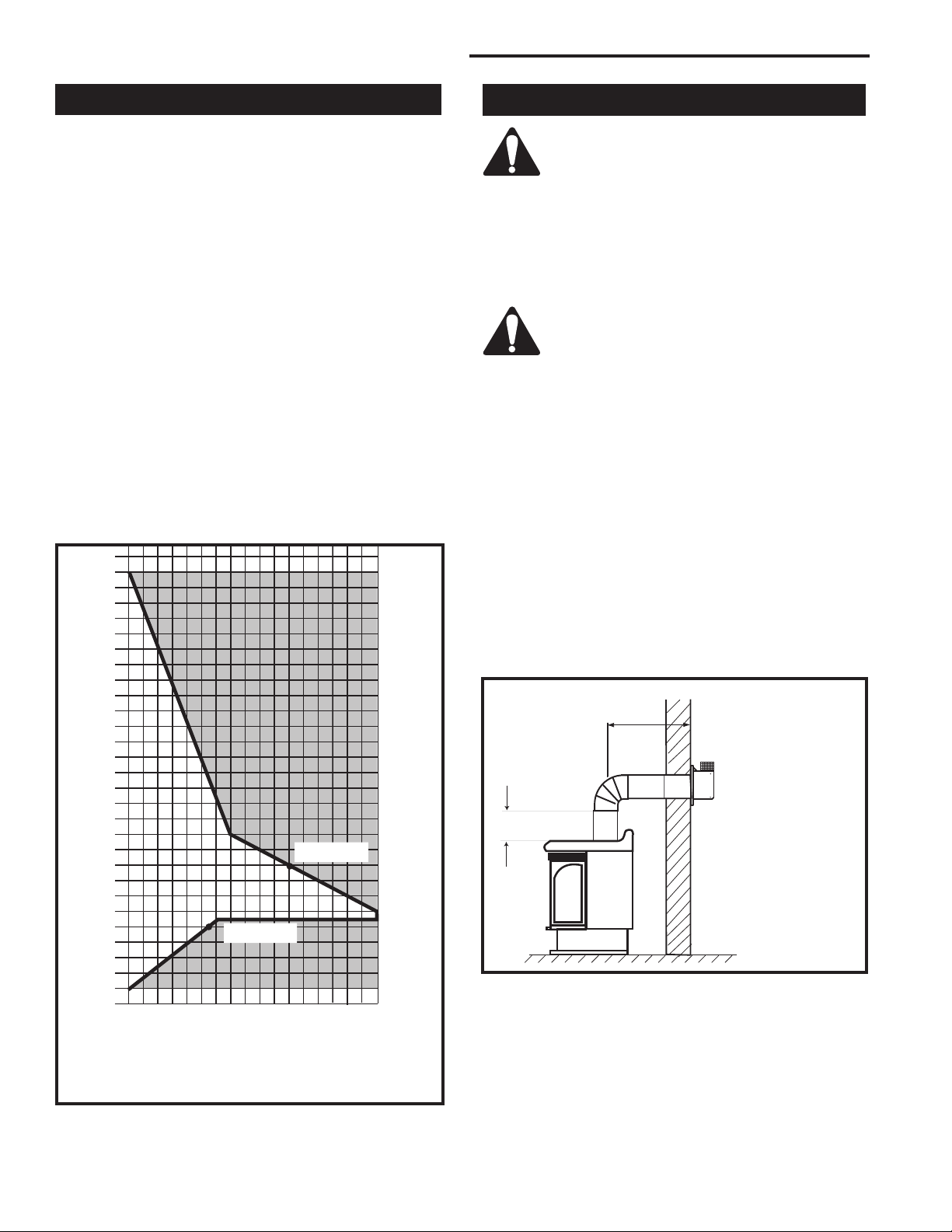
How to Use the Vent Graph
The vent chart should be read in conjunction with the
following vent installation instructions to determine the
relationship of the vertical and horizontal dimensions of
the vent system.
1. Determine the height of the center of the horizon
tal vent pipe exiting through the outer wall. Using
this dimension on the Sidewall Vent Graph (Fig. 8),
locate the point intersecting with the slanted graph
line.
2. From the point of this intersection, draw a vertical
line to the bottom of the graph.
3. Select the indicated dimension, and position the
fireplace in accordance with same.
Example A:
If the vertical dimension from the floor of the fireplace is
11’ (3.4m) the horizontal run to the face of the outer wall
must not exceed 14’ (4.3 m).
Example B:
If the vertical dimension from the floor of the unit is 7’
(2.14m), the horizontal run to the face of the outer wall
must not exceed 8¹⁄₂’ (2.6 m).
-
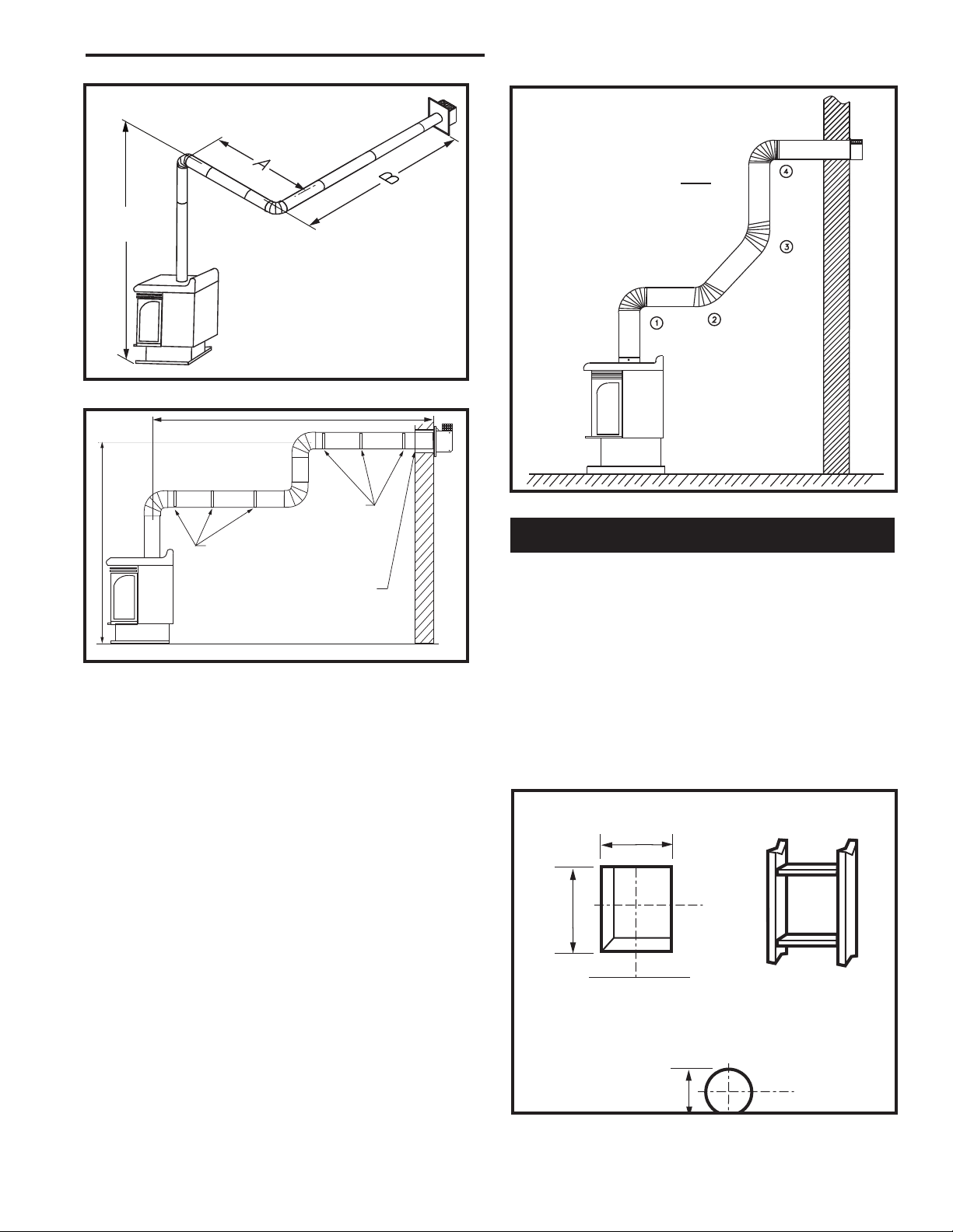
Vertical Sidewall Applications
Since it is very important that the venting system maintain its balance between
the combustion air intake and the flue
gas exhaust, certain limitations as to vent
configurations apply and must be strictly
adhered to.
The vent graph showing the relationship between vertical and horizontal side wall venting will help to determine the various dimensions allowable.
Minimum clearance between vent pipes
and combustible materials is one 1”
(25mm) on top, bottom and sides unless
otherwise noted.
When the vent termination exits through foundations
less than 20” (508 mm) below siding outcrop, the vent
pipe must flush up with the siding.
It is always best to locate the fireplace in such a way
that minimizes the number of offsets and horizontal vent
length of vent pipe from the flue collar of the fireplace to
the face of the outer wall.
Horizontal plane means no vertical rise exists on this
portion of the vent assembly.
Fig. 8 Sidewall venting graph. (Dimensions in feet)
10
Horizontal dimension from the outside face of the wall to
the center of the fireplace vent flange
Sidewall vent graph showing the relationship between vertical
and horizontal dimensions for a Direct Vent flue system.
• The maximum number of 90° elbows per side wall
Vertical dimension from the floor of the fireplace to
installations is three (3).
• For RFSDV24 and RFSDV34 models, the maximum
the center of the horizontal vent pipe
horizontal rn for a minimum 12” (305 mm) vertical
rise is 3’ (914 mm). (Fig. 9)
Fig. 9 Maximum horizontal run.
• If a 90° elbow is used in the horizontal vent run
(level height maintained) the maximum horizontal
vent length is reduced by 36” (914 mm). (Fig. 10)
This does not apply if the 90° elbows are used to
increase or redirect a vertical rise. (Fig. 11)
RFSDV24
RFSDV34
x = 12” (305 mm)
FP1495
10003550
Page 11
RFSDV24/34 Freestanding Direct Vent Gas Fireplace
7.5ʼ
(2286 mm)
20ʼ
(6 m)
7.5ʼ (2. m)
Example:
Elbow 1 = 90°
Elbow 2 = 45°
Elbow 3 = 45°
Elbow 4 = 90°
Total angular variation = 270°
A + B =17’ (5.2 m) Max.
FP1496
Fig. 10 90° elbow used in horizontal vent run.
Pipe Straps
Every 3’ (914 mm)
Pipe Straps Every 3’
(914 mm)
Fig. 11 90° elbow used to increase height.
Firestop / Zero
Clearance Sleeve
FP1497
Example: According to the chart the maximum
horizontal vent length is 20’ (6 m). However, if a
90° elbow is used in the horizontal vent, maximum
horizontal vent length is reduced to 17’ (5.2 m).
In Figure 9, the total of Dim. A and Dim. B must not
exceed 17’ (5.2 m).
• The maximum number of 45° elbows permitted per
installation is six (6). These elbows can be installed
in either the vertical or horizontal run.
• For each 45° elbow installed in the horizontal run,
the length of the horizontal run MUST be reduced by
18” (457 mm). This does not apply if the 45° elbows
are installed on the vertical part of the vent system.
• The maximum number of elbow degrees in a system
is 270°. (Fig. 12)
1 + 2 + 3 + 4 = 270°
FP1239
Fig. 12 Maximum elbow usage.
Vertical Sidewall Installations
STEP 1
Locate vent opening on the wall. It may be necessary
to first position the fireplace and measure to obtain hole
location. Depending on whether the wall is combustible
or noncombustible, cut opening to size. (Fig. 13)
For combustible walls first frame in opening.
Combustible Walls:
x 240 mm) hole through the exterior wall and frame as
shown.
Noncombustible Walls:
be 7¹⁄₂” (190 mm) in diameter.
Vent Opening for Combustible Wall
9³⁄₈”
(240mm)
Fireplace Hearth
Opening for Noncombustible Wall
(Fig. 13) Cut a 9³⁄₈”H x 9³⁄₈”W (240
(Fig. 13) Hole opening must
9³⁄₈”
(240mm)
Framing
Detail
10003550
7¹⁄₂”
(190mm)
VO584-100
Fig. 13 Locate vent opening on wall.
11
Page 12
RFSDV24/34 Freestanding Direct Vent Gas Fireplace
X
X
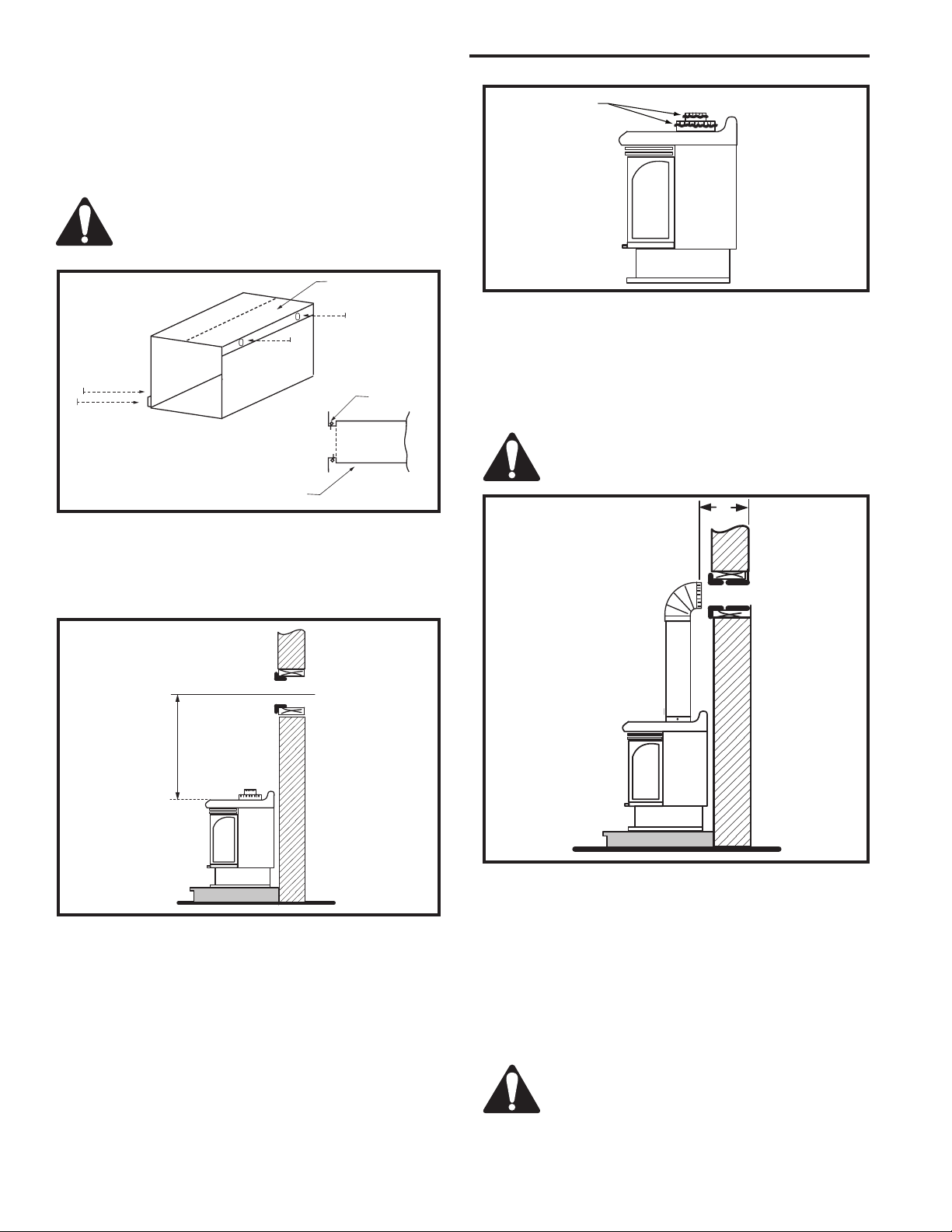
STEP 2
Measure wall thickness and cut zero clearance sleeve
parts to proper length (MAXIMUM 12”/305 mm). As
semble sleeve and attach to firestop with #8 sheet
metal screws (supplied). Install firestop assembly. (Fig.
14)
Zero clearance sleeve is only required for
combustible walls.
Adjustable
Zero Clearance
Sleeve
#8 Screws
(2)
Firestop
Adjustable Zero Clearance Sleeve
Fig. 14 Adjustable zero clearance sleeve.
Max. Length
12” (305mm)
#8 Screws (2)
#8 Screws
(2)
ZCS101
STEP 3
Place fireplace into position. (Fig. 15) Measure the ver
tical height (X) required from the base of the flue collars
to the center of the wall opening.
Bead of Sealant
FP1509
Fig. 16 Horizontal vent length.
STEP 5
Measure the horizontal length requirement including a
2” (51mm) overlap, ie from the elbow to the outside wall
face plus 2” (51mm) (or the distance required if installing a second 90° elbow). (Fig. 17)
Always install horizontal venting on a level
plane.
FP1510
FP1508
Fig. 15 Height to center of wall opening.
Fig. 17 Horizontal length to wall.
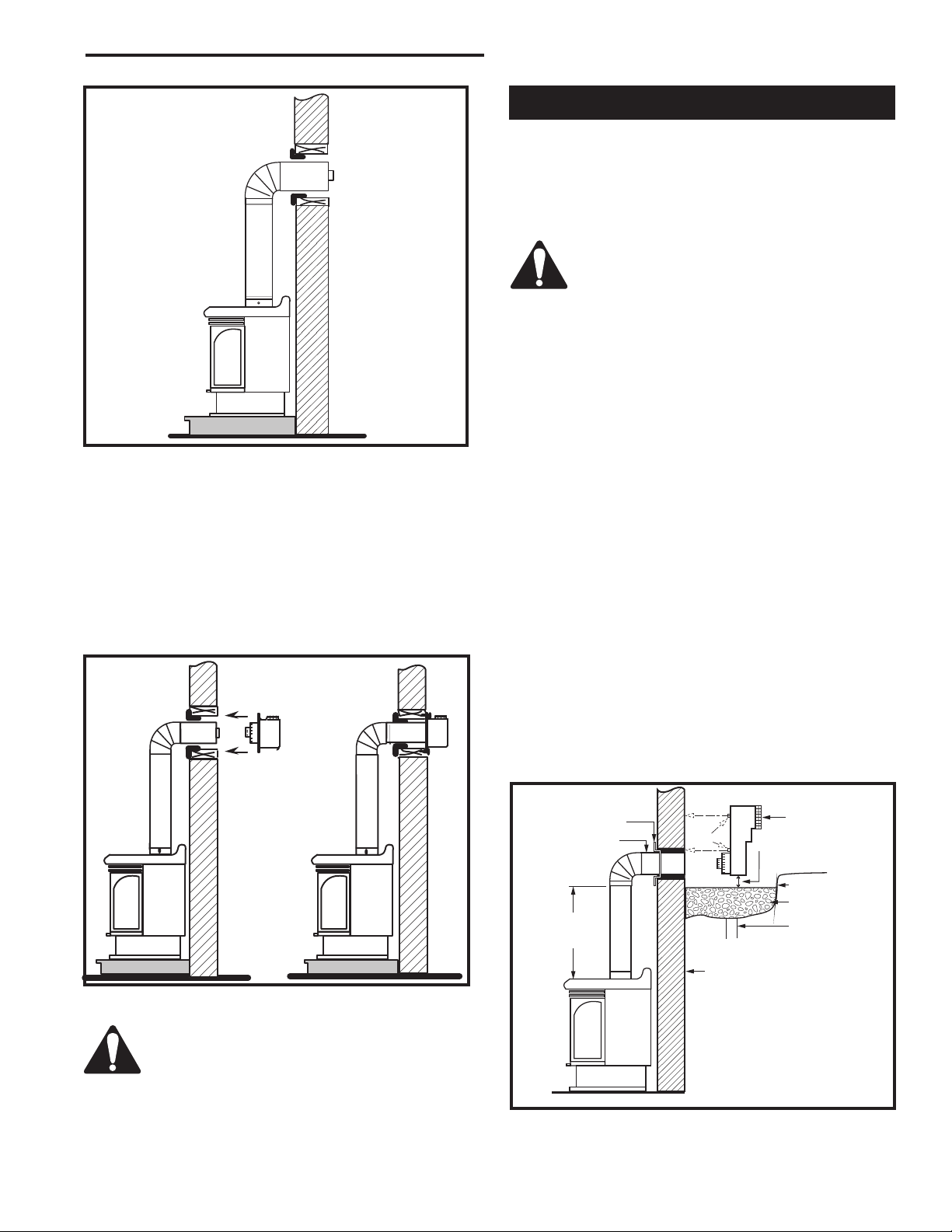
STEP 6
NOTE: If using charcoal wall plate Pt. #10000257,
and collar Pt. # 52203-CG, put them in place before
STEP 4
Apply a bead of high temperature sealant to the inner
and outer flue collars of the fireplace and using appropriate venting component(s) attach to fireplace with
three (3) screws. (Fig. 16) Follow with the installation
of the inner and outer elbow. Again secure joints as
described on Page 8.
putting the pipe sections through the wall.
Use appropriate length of pipe sections - telescopic or
fixed - and install the horizontal vent sections. The sections which go through the wall are packaged with the
starter kit, and can be cut to suit if necessary. (Fig. 18)
Sealing vent pipe and firestop gaps with
high temperature sealant will restrict cold
air being drawn in around fireplace.
12
10003550
Page 13
FP1511
24”
(610 mm)
Min.*
Fig. 18 Pipe sections through the wall.
STEP 7
Apply high temperature sealant to 4” (102 mm) and
7” (179 mm) collars or the termination one inch away
from crimped end. Guide the vent terminations 4” and
7” collars into their respective vent pipes. Double check
that the vent pipes overlap the collars by 2” (51 mm).
Secure the termination to the wall with screws provided
and caulk around the wall plate to weatherproof. (Fig.
19)
RFSDV24/34 Freestanding Direct Vent Gas Fireplace
Below Grade Installations
When it is not possible to meet the required vent terminal clearances of 12” (305 mm) above grade level a
snorkel vent kit is recommended. It allows installation
depth of down to 7” (178 mm) below grade level. The
7” is measured from the center of the horizontal vent
pipe as it penetrates through the wall.
If venting system is installed below
ground, we recommend a window well with
adequate and proper drainage.
Ensure sidewall venting clearances are
observed.
If installing a snorkel, a minimum 24” (610 mm) vertical
rise is necessary. The maximum horizontal run with
the 24” (610 mm) vertical pipe is 36” (914 mm). This
measurement is taken from the collar of the fireplace (or
transition elbow) to the face of the exterior wall. Refer to
the Sidewall Vent Graph for extended horizontal run if
the vertical rise exceeds 24” (610 mm).
1. Establish vent hole through the wall. (Fig. 13)
2. Remove soil to a depth of approximately 16”
(406 mm) below base of snorkel. Install drain pipe.
Install window well (not supplied). Refill hole with 12”
(305 mm) of coarse gravel leaving a clearance of
approximately 4” (102 mm) below snorkel. (Fig. 20)
3. Install vent system.
4. Ensure a watertight seal is made around the vent
pipe coming through the wall.
5. Apply high temperature sealant caulking (supplied)
around the 4” and 7“ snorkel collars.
6. Slide the snorkel into the vent pipes and secure to
the wall.
7. Level the soil to maintain a 4” (102 mm) clearance
below snorkel. (Fig. 20)
Fig. 19 Horizontal length to wall.
Support horizontal pipes every 3’ (914 mm)
with metal pipe straps.
Check fireplace to make sure it is leveled
and properly positioned.
10003550
FP1512
Firestop
7” Pipe
Fig. 20 Below grade installation.
Screws
*A minimum of 24” (610 mm)
vertical pipe must be installed
when using the 7TDVSNORK
Kit.
*The 22” (559 mm) vertical rise
(center to center) of the snorkel
may be included for calculationof
max. horizontal run.
7TDVSNORK
(Snorkel)
4” (102 mm)
Clearance
Min.
Window
Well
Drain
Foundation Wall
FP1513
13
Page 14

RFSDV24/34 Freestanding Direct Vent Gas Fireplace
Do not back fill around snorkel. A clear
ance of at least 4” (102 mm) must be maintained between snorkel and the soil.
If the foundation is recessed, use recess brackets (not
supplied) for securing lower portion of the snorkel.
Fasten brackets to wall first, then secure to snorkel
with self drilling #8 x 1/2 sheet metal screws. It will be
necessary to extend vent pipes out as far as protruding
wall face. (Fig. 21)
Snorkel
Foundation Recess
Recess Brackets
Watertight Seal
Around Pipe
Fig. 21 Snorkel installation, recessed foundation.
Wall Screws
Sheet Metal
Screws
BG401
Vertical Through-the-Roof Applications
Max.
8’
(2.4 m)
45°
Max.
8’
(2.4 m)
45°
Max. 40’
(12 m)
Typical
Roof Support
Application
Typical Straight-up Installation
Fig. 22 Vertical through-the-roof installation.
Typical
Ceiling
Support
Application
CFM140
This Gas Fireplace has been approved for:
• Vertical installations up to 40’ (12 m) in height. Up
to a 10’ (3 m) horizontal vent run can be installed
within the vent system using a maximum of two 90°
elbows.
• Up to two 45° elbows may be used within the
horizontal run. For each 45° elbow used on the
horizontal level the maximum horizontal length must
be reduced by 18” (457 mm).
Example: Maximum horizontal length
0 x 45° elbows = 10’ (3 m)
1 x 45° elbows = 8¹⁄₂’ (2.6 m)
2 x 45° elbows = 7’ (2.1 m)
• A minimum of an 8’ (2.4 m) vertical rise.
• Two sets of 45° elbows offsets within these vertical
installations. From 0 to a maximum of 8’ (2.4 m) of
vent pipe can be used between elbows. (Fig. 22)
• 7DVCS must be used to support offsets. (Fig. 22)
This application will require that you first determine
the roof pitch and use the appropriate starter kit.
(Refer to Venting Components List)
14
2’
(610 mm)
Minimum
CFM190
Fig. 23 Proper vent height.
Vertical Through-the-Roof Installation
1. Locate your fireplace.
2. Plumb to center of the 4” (102 mm) flue collar from
ceiling above and mark position.
3. Cut opening equal to 9
4.
Proceed to plumb for additional openings through
the roof. In all cases, the opening must provide a
minimum of 1” (25 mm) clearance to the vent pipe,
i.e., the hole must be at least 9³⁄₈” x 9³⁄₈” (240 x 240
mm).
5. Place fireplace into position.
6. Place firestop(s) #7DVFS or Attic Insulation Shield
#7DVAIS into position and secure. (Fig. 24)
³⁄₈” x 9³⁄₈” (240 x 240 mm).
10003550
Page 15

RFSDV24/34 Freestanding Direct Vent Gas Fireplace
11"
11"
7. Install roof support (Fig. 22) and roof flashing making
sure upper flange of flashing is below the shingles.
(Fig. 25)
8. Install appropriate pipe sections until the venting is
above the flashing. (Fig. 25)
9. Install storm collar and seal around the pipe.
10. Add additional vent lengths for proper height. (Fig.
23)
11. Apply high temperature sealant to 4” and 7” collars.
Attic Insulation
Shield
Joist
11” x 11” (295 x 295 mm)
Upper Floor
Ceiling Installation
Joist
If there is a room above ceiling level,
firestop spacer must be installed on both
the bottom and the top side of the ceiling
joists. If an attic is above ceiling level a
7DVAIS (Attic Insulation Shield) must be
installed.
The enlarged ends of the vent section
always face downward. (Fig. 25)
#8 Sheet Metal Screws
(3 per joint)
Sealant
Storm Collar
TWL101a
Fig. 25 Roof flashing.
Fig. 24 Place firestop spacer(s) and secure.
Firestop Spacer
Nails (4)
FP1516
10003550
15
Page 16

RFSDV24/34 Freestanding Direct Vent Gas Fireplace
Twist Lock Venting Components
Starter Kit - Model 7TFSMSK
Starter Kit - Model 7TFSDVSK
Starter Kit - Model 7TDVSKV - Vertical Venting
for 7TDVSKV-A, order 1/12 to 6/12 roof pitch
for 7TDVSKV-B, order 7/12 to 12/12 roof pitch
for 7TDSKV-F, order flat roof
Starter Kit - Model 7TFSDVSKS - Snorkel Kit
for below grade installation
45° Elbow Kit
7TFSDV45 for Vertical Installation Offsets
90° Transition Elbow Kit
7TFSDV90 fo Vertical Sidewall Applications
or Through-the-Roof
Telescopic Vent Sections
7TDVP1218 12” to 18” adjustable length
7TDVP3564 35” to 64” adjustable length
Pipe sections for vertical or horizontal venting
Model 7TDVP8” 4 per box
Model 7TDVP12” 4 per box
Model 7TFSDVP24”
Model 7TDVP36”
Model 7TFSDVP48”
Firestop Spacer
Model 7DVFS
Attic Insulation Shield
Model 7DVAIS
Vertical/Horizontal Combination Offset Support
Model 7DVCS
16
10003550
Page 17

RFSDV24/34 Freestanding Direct Vent Gas Fireplace
Operating Instructions
Glass Information
Only glass approved by CFM Corporation may be
used for replacement. The use of substitute glass
will void all product warranties.
Take care to avoid breaking the glass.
Under no circumstances is this fireplace
to be operated without the front glass or
with a broken glass. Replacement of the
glass (with gasket) as supplied by the
manufacturer should be done by a licensed
qualified service person.
Window Frame Assembly Removal
1. Turn the gas supply OFF (Refer to Lighting
Instructions).
2. If the unit has been operating allow time for the
components to cool.
3. Open the two side doors.
4. Open the clamps on the two sides. (Fig. 26)
5. Pull the frame forward.
6. To reinstall window frame assembly, follow the
above procedure in reverse.
Release Clamps
(2 per side)
FP1517
Fig. 26 Window frame removal.
Glass Cleaning
It is necessary to periodically clean the glass. During
start-up condensation, which is normal, forms on the
inside of the glass. This condensation causes lint, dust
and other airborne particles to cling to the glass surface.
Also initial paint curing may deposit a slight film on
the glass. It is therefore recommended that the glass
be cleaned two or three times with a non-ammonia
based household cleaner and warm water (We
recommend gas fireplace glass cleaner) within the
first few weeks of operation.
After the initial cleaning process the glass should be
cleaned two or three times during each operating
season depending on the environment in the house.
Clean the glass after the first two weeks of
operation.
Do not clean glass when hot.
Do not use abrasive cleaners.
Do not strike or slam glass.
Log Identification Chart
Logs RFSDV24 RFSDV34
Log Ember Bed -- KR7
Log - Front Left KR13 KR8
Log - Front Right KR14 KR9
Log - Rear -- KR10
Log - Top Left -- KR11
Log - Top Right -- KR12
Log - Rear Left KR15 - Log - Rear Right KR16 --
Log Set and Lava Rock Material Installation
For Model RFSDV24 (Refer to Fig. 27)
1. Remove window frame assembly. (Refer to Window
Frame Assembly Removal section)
2. Remove logs from packaging.
As with all plastic items - these logs and
their packaging are not toys and should be
kept away from children and infants.
3. Place rear left log (KR15) with one end onto the
left rear bracket while the rest of the log sets on the
center of the rear log support.
4. Place the rear right log (KR16) onto the right side of
the rear log support. Ensure the log’s bottom holes
are located on the two studs of the support.
5. Place front left log (KR13) onto the left cut out of
the rear log while the front left end of this log will set
against the back wall of the front grate.
6. Place the front right log (KR14) in position by resting
the holes under one end of this log located over the
knob on the rear left log while the other end of the
log set against the right end of the front grate. (Fig.
27)
7. Place burner lava rock over front area of the burner.
10003550
17
Page 18

RFSDV24/34 Freestanding Direct Vent Gas Fireplace
For Model RFSDV34 (Refer to Fig. 28)
1. Remove window frame assembly.
(Refer to Window Frame Assembly
Removal section)
2. Remove logs from packaging.
As with all plastic items - these
logs and their packaging are
not toys and should be kept
away from children and infants.
3. Place rear log (KR10) n rear bracket
(ensure log is seated properly, leveled
and centered to the unit) so it will not
move from side to side and it is firmly
positioned on the bracket.
4. Slip front ember log (KR7) down behind
the front deflector.
5. Place front left log (KR8*) on top of
burner, left side. Using the bottom holes
in the log, locate it into the left bracket
log locator studs.
6. Place front right log (KR9) on top
of burner, right side. Use log’s
bottom holes to locate it into the
Log Top Left
(KR11)
right bracket log locator studs.
7. Place burner lava rock on top
of burner between the em-
Figure 28
RFSDV34
ber log and the two front
logs.
8. Place top left log (KR11)
onto locator notches.
Log Front Left
(KR8)
Ensure the log is secure.
9. Place top right log
(KR12) onto locator
notches. Ensure the log
is secure.
Log Ember
Bed (KR7)
Figure 27
RFSDV24
Log Front Left
(KR13)
Log Rear Left (KR15)
Log Rear Right (KR16)
LG345
Log Front
Right (KR14)
Burner Lava Rock
Log Rear (KR10)
Log Top Right (KR12)
18
LG344
Log Front Right (KR9)
10003550
Page 19

RFSDV24/34 Freestanding Direct Vent Gas Fireplace
Turn
counterclockwise
to decrease
flame height
Turn clockwise
to increase
flame height
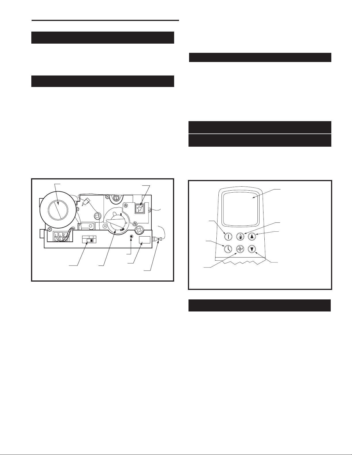
Flame & Temperature Adjustment
RN/RP Models
For units equipped with ‘HI/LO’ valves the flame
adjustment is accomplished by rotating the ‘HI/LO’
adjustment knob located near the center of the gas
control valve. (Fig. 29)
Fig. 29 Flame adjustment knob for Honeywell valve.
RFN/RFP Models
For units equipped with the Honeywell Radio
Frequency control valve, all adjustments are performed
with the use of a remote transmitter. Refer to
instructions packaged with the transmitter or Page 20 in
this manuals for operating instructions.
Flame Characteristics
It is important to periodically perform a visual check
of the pilot and burner flames. Compare them to the
pictorials illustrated below (Fig. 30-31).
If the flame patterns appear abnormal contact a
qualified service provider for service and adjustment.
3/8” - 1/2”
(10 - 13 mm)
F584-703
Fig. 30 Correct pilot flame appearance.
Figure 31
RFSDV24
LG346
RFSDV34
10003550
LG347
19
Page 20

RFSDV24/34 Freestanding Direct Vent Gas Fireplace
PILOT
ON
OFF
ON
P
I
L
O
T
O
F
F
O
F
F
5
4
3
2
1
O
F
F
P
i
l
o
t
3/8" - 1/2"
Lighting and Operating Instructions
FOR YOUR SAFETY READ BEFORE LIGHTING
WARNING:If you do not follow these instructions exactly, a fire or explosion
may result causing property damage, personal injury or loss of life.
A. This heater has a pilot which must be lit manu
ally. When lighting the pilot follow these instructions exactly.
B. BEFORE LIGHTING smell all around the
heater area for gas. Be sure to smell next to
the floor because some gas is heavier than air
and will settle on the floor.
WHAT TO DO IF YOU SMELL GAS
• Do not try to light any fireplace
• Do not touch any electric switch
• Do not use any phone in your building
• Immediately call your gas supplier from a
neighbor’s phone.
Lighting Instructions
-
Follow the gas supplier’s instructions.
• If you cannot reach your gas supplier, call
the Fire Department
C. Use only your hand to push in or turn the gas
control knob. Never use tools. If the knob will not
push in or turn by hand, do not try to repair it, call a
qualified service technician. Applying force or any
attempted repair may result in a fire or explosion.
D. Do not use this fireplace if any part has been under
water. Immediately call a qualified service technician to inspect the heater and to replace any part of
the control system and any gas control which has
been under water.
1. STOP! Read the safety information above.
2. Turn off all electrical power to the fireplace.
3. For MN/MP/TN/TP appliances ONLY, go on to
Step 4. For RN/RP appliances turn the ON/OFF
switch to “OFF” position or set thermostat to
lowest level.
4. Open control access panel.
5. Push in gas control knob slightly and turn clockwise to “OFF”.
Euro SIT SIT NOVA
Honeywell
6. Wait five (5) minutes to clear out any gas. Then
smell for gas, including near the floor. If you
smell gas, STOP! Follow “B” in the safety information above. If you do not smell gas, go to the
next step.
7. Remove glass door before lighting pilot. (See
Glass Frame Removal section).
8. Visibly locate pilot by the main burner.
9. Turn knob on gas control counterclockwise
to “PILOT”.
10. Push the control knob all the way in and hold.
Immediately light the pilot by repeatedly depressing the piezo spark ignitor until a flame appears.
Continue to hold the control knob in for about one
(1) minute after the pilot is lit. Release knob and it
will pop back up. Pilot should remain lit. If it goes
out, repeat steps 5 through 8.
• If knob does not pop up when released, stop
and immediately call your service technician or
gas supplier.
• If after several tries, the pilot will not stay lit,
turn the gas control knob to “OFF” and call your
service technician or gas supplier.
11. Replace glass door.
12. Turn gas control knob to “ON” position.
13. For RN/RP appliances turn the ON/OFF switch to
“ON” position or set thermostat to desired setting.
14. Turn on all electrical power to the fireplace.
1. Turn the ON/OFF switch to Off position or set
the thermostat to lowest setting.
2. Turn off all electric power to the fireplace if
service is to be performed.
20
To Turn Off Gas To Heater
3. Open control access panel.
4. Push in gas control knob slightly and turn clockwise to “OFF”. Do not force.
5. Close control access panel.
10003550
Page 21
RFSDV24/34 Freestanding Direct Vent Gas Fireplace
LOCAL
REMOTE
O
N
•
P
IL
O
T
OFF
•
LED
Instructions for RF Comfort Control Valve
The Comfort Control Valve allows remote control of
temperature, fan and flame appearance.
NOTE: The antenna should hang in free air away from
grounded metal.
Operation
1. If the manual switch is in remote position, switch it to
LOCAL. (Fig. 32)
2. Turn the pilotstat knob counterclockwise from OFF
to the PILOT position, push the knob down, and hold
in position. The pilot valve opens and allows gas to
flow to the pilot burner.
3. Push plunger on the piezo until the pilot burner is lit.
When the pilot burner is lit, the LED on the control
will come on after approximately 40 seconds and will
be continuously red. When the light turns off which
will be approximately 10 seconds after it has been
continuously red, the receiver/valve is fully powered.
Motor Top
Cap
Local/
Remote Switch
Pilotstat
Knob
Fig. 32 Comfort control valve.
4. Release the knob. The shaft will move upward. The
pilot burner should now stay burning. If the pilot
burner goes out, repeat step 2.
5. Turn the knob counterclockwise to the ON position. If
the manual switch is in the LOCAL position, the main
burner will turn on immediately.
6. ON the initial use of a transmitter, a recognition
operation is required between the receiver/valve
and transmitter. Change the switch from LOCAL
to REMOTE. Press the fan or flame button on the
transmitter within 30 seconds. The LED will blink
indicating the transmitter will now work with the receiver/valve. If the switch continues in the REMOTE
position, the transmitter will now control the main
valve, flame modulation level and fan control.
Piezo Ignitor
LED
Plug
Antenna
FP1037
7. If the manual switch is in the LOCAL position, the
valve will be at the highest fixed pressure setting.
The transmitter will control the fan only.
Shut Off Procedure
If the manual switch is in the REMOTE position, the
transmitter can shut off the main burner and fan. However, the control is still on and a command from the
transmitter can turn on the main burner or fan.
To shut off the system, turn the pilotstat knob clockwise
to the OFF position. This action closes the main gas
and safety valves. The transmitter cannot turn on the
main burner or fan.
Transmitter Operation
Off Mode
In the OFF mode, the fireplace flame and fan are
off, the display will show OFF and displays the room
temperature. If the receiver is in REMOTE mode, the
fireplace will shut off.
Display
Room Temperature
Set Temperature
Flame Height Level
Mode
Auto
On
Off
Countdown
Timer
Fan
FP1039
Fig. 33 Transmitter diagram.
Fan Speed Level
Countdown Timer
Low Battery
Flame
Up
Increases Flame
Height, Fan Speed
Timer, or Set Point
Down
Decrease
Flame, Fan
Speed Timer
or Set Point
On (Manual) Mode
In the ON mode, the room temperature, flame and fan
levels will be shown. MANUAL will appear next to both
the flame and fan icons.
When the control is in the ON mode, the flame and fan
levels, and delay timer are changed with the up and
down buttons. To change the flame level, press the
flame button followed by an arrow key. To change the
fan level, press the fan key followed by an arrow key.
Pushing the arrow key once will change the level by
one unit.
10003550
FP297A
21
Page 22

RFSDV24/34 Freestanding Direct Vent Gas Fireplace
FAN
Antenna
Red
White
Red
White
Delay Timer Mode
The shut off delay timer has a maximum of 2 hours and
a minimum of zero minutes. To change the timer level,
press the time key followed by an arrow key. Pushing
the key once will change the timer by 10 minutes.
Auto Mode
In the AUTO mode, the room temperature, set temperature, flame and fan levels will be shown. AUTO will
appear next to both the flame and fan icons.
When the control is in the AUTO mode, the main burner
will turn on/off or modulate based on the heat needed
to maintain the set temperature. The flame level will
change automatically to optimize the heat output
needed to maintain the set temperature. To change the
set temperature, press the up or down key. Pushing a
key once will change the temperature by one degree.
In the AUTO mode, the fan speed will increase with
increasing flame height or decrease with decreasing
flame height. “AUTO” is displayed next to the flame and
fan icons.
Pilot Assembly
FP1038
Fig. 34 Comfort Valve wiring diagram.
Valve
(Bottom View)
Troubleshooting
Fan
White Dots
Fan Override During Auto Mode
If a lower or higher fan speed is desired when operating
in the AUTO mode, the fan speed can be overridden by
pushing the fan button followed by the up or down key.
Pushing a key once will change the fan level by one
unit. In this mode “AUTO” is displayed next to the flame
icon and “MANUAL” is displayed next to the fan icon.
Change Between F/C Temperature Units
Push the up and down arrow keys simultaneously for
at least 3 seconds to toggle between Fahrenheit and
Celsius units.
Disable Thermostat Function
To disable the thermostat function in the AUTO mode,
push the time and down keys simultaneously for at
least 3 seconds.
To Change Batteries
1. Remove cover on the backside of the transmitter.
Install 3 AAA batteries as shown and reattach cover.
2. Once steps 1-3 in OPERATION are completed,
receiver/valve and transmitter are now ready. Press
any button on transmitter for recognition process to
occur between the receiver/valve and transmitter.
3. Use functions as described in TRANSMITTER sec
tion.
-
1. Locate LED light on valve.
2. LED will blink after every valid command received by
the transmitter; this is not an error.
3. Failure codes may occur anytime after pilot burner is
lit.
4. Sequence is failure code followed by light not blink
-
ing for 30 seconds.
5. In the event of multiple failure codes, next failure
code follows previous failure code by approximately
3 seconds.
If an Error Code 3 is observed while performing the
testing, complete the following:
1. Make sure the spade connectors are pushed all the
way on. If the Error Code 3 is still showing, then go
to the next step.
2. Switch the front two thermopile leads with the back
two. Be sure the white lead is connected to the
spade with the white dot next to it. If the Error Code
3 is still showing, replace the thermopiles.
If an Error Code 8 is observed while performing the
testing, complete the following:
1. Confirm the valve is not in REMOTE mode.
• If the valve is producing Error Code 8 and in RE-
MOTE mode, the valve is defective and should be
replaced.
• If the valve is in LOCAL mode and producing Er-
ror Code 8, then go to the next step.
22
10003550
Page 23

2. Slide the Remote/Local switch to REMOTE and
teach the valve a transmitter (refer to Item 6, page
32). The Error Code will clear itself after approximately 1¹⁄₂ minutes and return to normal operation.
LED Count Service Action
8 Replace valve
7 Confirm stepper motor connection
exists
5 Confirm fan connection exists and
works
4 Confirm gas type; jumper in place
3 Replace thermopiles
2 Turn fan ON
NOTE: Some keys are not active.
RFSDV24/34 Freestanding Direct Vent Gas Fireplace
Auto Path
If the manual switch is
set to REMOTE, press
the mode button to
display AUTO on the
transmitter. Does the
transmitter display the
room and temperature
setting?
Yes
If the setting is above
room temperature on
the transmitter, does the
main valve and fan turn
on?
Yes
If the setting is below
room temperature on
the transmitter, does
the main valve and fan
turn off?
No
No
Move switch
from LOCAL to
REMOTE. Press
any key within 30
seconds.
Turn pilotstat knob
to OFF to turn valve
completely off
10003550
23
Page 24

RFSDV24/34 Freestanding Direct Vent Gas Fireplace
Comfort Valve system control sequence of operation with transmitter
Set manual switch
to local or remote
Light pilot burner
Did the LED stop
blinking?
Release pilotstat
knob
Yes
Turn pilotstat knob
from PILOT to ON
Five minute wait
Yes
Review LED fail-
once and leave in
remote. Press any
key on transmit-
ter for recognition
period
ure analysis
Cycle switch
Choose Local or
Remote path. Set
switch to manual or
remote
operation
If manual switch is
set to LOCAL, did
main burner light?
Yes
Transmitter con-
trols fan
Yes
Turn pilotstat knob
to PILOT to turn
off main burner
Turn pilotstat knob
to OFF to turn
valve completely
off
Local Path
No
Move switch from
local to remote.
Press any key on
transmitter. Move
switch back to
local
On Path
If the manual switch
is set to REMOTE,
press the mode but-
ton to display “ON”.
Does transmitter con-
trol the main burner
and fan?
Yes
Does transmitter
change levels of
flame height, fan
speed and set
temperature?
Yes
Set levels of flame
height and fan to
“0” to shut off main
burner and fan
Turn pilotstat knob
to OFF to turn
valve completely
off
Move switch from
manual to remote.
Press any key on
transmitter.
No
24
10003550
Page 25

Gas Supply ON
• Supply line hooked up
• Shutoff valve open
NO
NO
NO
NO
• Lockout has engaged. Wait
60 seconds and try again.
• For spark at electrode while
depressing Piezo - 1/8" gap to
pilot hood needed.
• All wiring connections
• Replace Piezo ignitor
• For air in lines
• Thermopile needs a minimum
325mV. Adjust pilot flame height.
• All Wiring connections
• Replace thermopile
• Thermocouple needs a minimum
14mV.
• Defective valve. Turn to pilot,
meter should read greater than
100mV. If not, replace.
Pilot Lights with
Piezo Ignitor
YES
YES
YES
YES
Pilot Stays Lit
Pilot Lights
Main Burner
System OK
START
CHECK
• Valve is turned on
• Wall switch is not turned on.
Watch for grounded wires!
• Thermopile needs a minimum
325mV.
• Plugged burner orifice.
Honeywell VS8420 Standing Pilot
RFSDV24/34 Freestanding Direct Vent Gas Fireplace
Troubleshooting
Remove Glass Panel Before Servicing.
10003550
FP396a
25
Page 26

RFSDV24/34 Freestanding Direct Vent Gas Fireplace
Maintenance
Burner and Burner Compartment
It is important to keep the burner and the burner
compartment clean. At least once per year the logs and
lava rock/ember material should be removed and the
burner compartment vacuumed and wiped out. Remove
and refit the logs as per the instructions in this manual.
Always handle the logs with care as they
are fragile and may also be hot if the
fireplace has been in use.
FK24 Fan Assembly
The fan unit requires periodic cleaning. At least once
per month in the operating season open the lower
louvre panels and wipe or vacuum the area around the
fan to remove any build up of dust or lint.
Brass Trim
Clean the brass trim pieces using a soft cloth lightly
dampened with lemon oil. Do not use water or
household cleaners on any brass components.
To obtain proper operation, it is imperative that the pilot
and burner’s flame characteristics are steady, not lifting
or floating.
Typically, the top 3/8” to 1/2” of the thermopile should
be engulfed in the pilot flame. (Refer to Page 18, Figure
30)
To adjust pilot burner: (by qualified service technician)
1. Remove pilot adjustment cap
2. Adjust pilot screw to provide properly sized flame.
3. Replace pilot adjustment cap.
The primary air shutter is set at factory and should
only be adjusted, if necessary, by a qualified service
technician.
Cleaning the Standing
Pilot Control System
The burner and control system consist of:
• burner tube • gas orifice
• pilot assembly • thermopile
• millivolt gas valve
Most of these components may require only an
occasional checkup and cleaning and some may
require adjustment. If repair is necessary, it should
be performed by a qualified technician.
1. Turn off pilot light at gas valve.
2. Allow fireplace to cool if it has been operating.
3. Remove window frame assembly. (Refer to Window
Frame Assembly Removal section.)
4. Remove logs.
5. Vacuum burner compartment especially around
orifice primary air openings.
6. Visually inspect pilot. Brush or blow away any dust
or lint accumulation.
7. Reinstall logs.
8. Ignite pilot - Refer to Lighting Instructions.
9. Reinstall window frame assembly.
26
10003550
Page 27

RFSDV24/34 Freestanding Direct Vent Gas Fireplace
L
O
H
I
PILOT
ADJ
PILOT
ON
OFF
3
14
18c/d
20
37
21
24
27
28
29
30
32
9c/d
11a
10
13b
8a/b
11a
13a
14
11b
39
13b
17
15
O
N
P
I
L
O
T
O
F
F
14
18a/b
38
1b
1a
1c
1d
1e
1f
34
40
31
9a/b
1b
1h
1g
1b
RFSDV24
RFSDV34
2
4
19
CFM Corporation reserves the right to make changes in design, materials, specifications, prices and discontinue colors and products at any time,
without notice.
RFSDV24/34 Units: V21A00, V21B00, U21K00, U21L00
Ref. Description RFSDV24 RFSDV34
1. Log Set Complete 10003538 10001763
1a. Log - Ember Bed -- KR7
1b. Log - Front Left KR13 KR8
1c. Log - Front Right KR14 KR9
1d. Log - Rear -- KR10
1e. Log - Top Left -- KR11
10003550
27
Page 28

RFSDV24/34 Freestanding Direct Vent Gas Fireplace
RFSDV24/34 (continued)
Ref. Description RFSDV24 RFSDV34
1f. Log - Top Right -- KR12
1g. Log - Rear Left KR15 - 1h. Log - Rear Right KR16 --
2. Lava Rock 57897 57897
3. Burner Housing Assembly w/tiles 10003559 10001272
4. Ceramic Tile (single) 57803 57803
5a. Orifice, Main Burner - Nat. (not shown) Refer to Rating Plate
5b. Orifice, Main Burner - Prop. (not shown) Refer to Rating Plate
5c. Orifice, Front Burner - Nat. (not shown) Refer to Rating Plate
5d. Orifice, Front Burner - Prop (not shown) Refer to Rating Plate
6a. Orifice, Top Convertible Pilot - Nat. (not shown) 10002268 10002268
6b. Orifice, Top Convertible Pilot - Prop. (not shown) 10002269 10002269
7a. Orifice, Radio Frequency Pilot - Nat. (not shown) -- 20000908
7b. Orifice, Radio Frequency Pilot - Prop (not shown) -- 20000907
8a. Pilot Assembly, Radio Frequency - Nat. -- 20002266
8b. Pilot Assembly, Radio Frequency - Prop. -- 20002268
9a. Pilot Assembly, 3 way DV Top Conv. - Nat. 10002264 10002264
9b. Pilot Assembly, 3 way DV Top Conv. - Prop. 10002265 10002265
9c. Pilot Assembly, PSE - Nat. -- 10001741 (RMH)
9d. Pilot Assembly, PSE - Prop. -- 10001742 (RMH)
10. Pilot w/Electrode & Cable PSE -- 10002501
11a. Pilot Tube w/fittings PSE -- 10003279
11b. Pilot Tube w/fittings SIT 10001296 --
12. Manifold Tube w/fittings (not shown) 10002492 57318
13a. Thermopile, Radio Frequency -- 20002400
13b. Thermopile, RN & RP 53373 53373
14. Ignitor Piezo, Honeywell Valve 20000062 20000062
15. Transmitter -- 20002047
16. Manifold Assembly (not shown) 10003207 10000824
17. Electrode ignitor w/cable 24” (not shown) 10001297 10001297 (RMH)
18a. Valve, Honeywell Radio Frequency - Nat. -- 20003719
18b. Valve, Honeywell Radio Frequency - Prop. -- 20003720
18c. Valve, Honeywell, RN 10001782 10001782 (RMH)
18d. Valve, Honeywell, RP 10001759 10001759 (RMH)
19. Electric Cord Set, Radio Frequency Valve -- 20002541
20. Fan Assembly w/bracket 54103 54103
21. Remote ON/OFF Switch 53606 53606
22. Wiring Harness - Remote Switch (not shown) 57265 57265
23. Remote ON/OFF Switch Kit (not shown) 53859 53859
24. Window Frame Assembly (complete with glass) 10003547 10001917
25. Window Glass w/Gasket Assembly Kit (not shown) 10003549 10001916
26. Window Glass Gasket Kit 10001983 10001983
27. Front Louvre Assembly 10003537 10001370
28. Cabinet Side Door 10003541 10001792
29. Control Door Assembly 10003539 10001790
30. Clamp 10000949 10000949
31. Antennae -- 20003561
28
10003550
Page 29

RFSDV24/34 Freestanding Direct Vent Gas Fireplace
RFSDV24/34 (continued)
Ref. Description RFSDV24 RFSDV34
32. Top Grille Panel 10001791 10001791
33. Magnet, Ceramic Side Doors (not shown) 10001705 10001705
34. Screen Cabinet Top 10001749 10001749
35. Plate Relief w/Gasket Assembly (not shown) 10002862 10002862
36. Front Grate Assembly - Charcoal Gray 10003535 --
37. Sensor Fan 51704 --
38. Speed Control 51738 --
39. Thermocouple SIT 53373 --
40. Relief Plate w/Gasket Assembly Burner Tray -- 10004192
10003550
29
Page 30

RFSDV24/34 Freestanding Direct Vent Gas Fireplace
For Use in Mobile Homes: Model RFSDV34RMH
This appliance may be installed as an OEM installation in a manufactured (mobile) home and must be installed in
accordance with the manufacturer’s instructions and the manufactured home construction and safety standard, Title
24 CFR, Part 3280 or Standard for Installation in Mobile Homes, CAN/CSA Z240 MH.
This appliance is only for use with the type(s) of gas indicated on the rating plate. A conversion kit is supplied with
the appliance.
This gas fireplace should be installed by a qualified
installer in accordance with local building codes, current
CSA-B149.1 Installation Codes for Gas Burning Fireplaces
and Equipment, and CAN/CSA Z240.4 Canada.
A manufactured home (mobile home) OEM installation
must conform with the Manufactured Home Construction and Safety Standard, Title 24 CFR, Part 3280, or
when such a standard is not applicable, the Standard for
Manufactured Home Installations, ANSI NCSBCS A225.1,
or Standard for Gas Equipped Recreational Vehicles and
Mobile Housing CSA Z240.4.
The appliance when installed, must be electrically grounded in accordance with local codes or, in the absence of
local codes, with the National Electrical Code, ANSI/NFPA
70, or the Canadian Electrical Code, CSA C22.1.
FOR SAFE INSTALLATION AND OPERATION PLEASE
NOTE THE FOLLOWING:
1 . This fireplace gives off high temperatures and should be
located out of high traffic areas and away from furniture
and draperies.
2. Children and adults should be alerted to the hazards of the
high surface temperatures of this fireplace and should stay
away to avoid burns or ignition of clothing.
3. CAUTION: Due to high glass surface temperature chil-
dren should be carefully supervised when in the same
room as fireplace.
4. Under no circumstances should this fireplace be modified.
Parts removed for servicing should be replaced prior to
operating this fireplace again.
5. Installation and any repairs to this fireplace must be per
formed by a qualified installer, service agency or gas sup
plier. A professional service person should be contacted to
inspect the fireplace annually. More frequent cleaning may
be required due to excess lint and dust from carpeting,
bedding material, etc.
6. Control compartments, burners and air passages in this
fireplace should be kept clean and free of dust and lint.
Make sure that the gas valve and pilot light are turned off
before you attempt to clean this fireplace.
7. The venting system (chimney) of this fireplace should be
checked at least once a year and if needed your venting
system should be cleaned.
8. Keep the area around your fireplace clear of combusti
ble materials, gasoline and other flammable vapour and
liquids. This fireplace should not be used as a drying rack
for clothing, nor should Christmas stockings or decorations
be hung on or around the fireplace.
9. Under no circumstances should any solid fuels (wood,
coal, paper or cardboard etc.) be used in this fireplace.
10. The flow of combustion and ventilation air must not be
obstructed in any way.
11. When the fireplace is installed directly on carpeting,
-
-
-
vinyl tile or any combustible material other than wood,
this fireplace must be installed on a metal or wood panel
extending the full width and depth of the fireplace.
12. This fireplace requires adequate ventilation and
combustion air to operate properly.
NOTE: Model RFSDV34RMH must be firmly attached to the
building.
Conversion Instructions
1. Disconnect the power to the unit and shut off the gas
supply.
2. Remove the window frame assembly. (Refer to Window
Frame Assembly Removal section.)
3. Carefully remove the logs
4. Remove the pilot assembly from bracket.
5. Remove the screws which are holding the burner housing
assembly in place.
6. Remove the burner housing assembly.
7. Remove the main and front orifice and replace with the
orifice supplied in the conversion kit. Use the small orifice
size for the front burner and the bigger orifice size for the
main burner.
8. Remove the compression fitting which holds the aluminium
tubing in the pilot assembly. This will reveal the pilot orifice
which must be replaced with the one provided in the
conversion kit.
9. Units with SIT Valve: (refer to pictures in the installation
instructions supplied with the conversion kit)
a) Using a Torx T20 or slotted screwdriver, remove and
save the three pressure regulator mounting screws (A),
pressure regulator tower (B) and diaphragm (C).
b) Ensure the rubber gasket (D) is properly positioned and
install the new Hi/Lo pressure regulator to the valve using
the new screws (E) supplied with the kit. Tighten screws
securely. (Ref. torque: 25 inLb)
c) Install the enclosed identification label (F) to the valve
body where it can be easily seen.
Units with Honeywell Valve:
The Honeywell valve fitted to this unit is preset for LP gas.
It is convertible to natural gas by the installation of a color
coded “conversion screw.” To insert the conversion screw,
refer to the instructions and diagrams in the Honeywell
Installation Instructions supplied in he conversion kit
packaged with the RFSDV34RMH unit.
10. Reassemble the fireplace in the reverse order, except for
the window frame assembly. Leave this off until the unit
has been checked for leaks and the gas supply line has
been bled.
11. After bleeding the gas line and checking for leaks with a
soap solution, replace the window frame assembly. Fire
up the unit, check the flame impingement on the logs,
adjusting them if necessary. Check the manifold and
supply pressures.
NOTE: If further assistance is required, refer to
Troubleshooting and Parts List in this manual.
30
10003550
Page 31
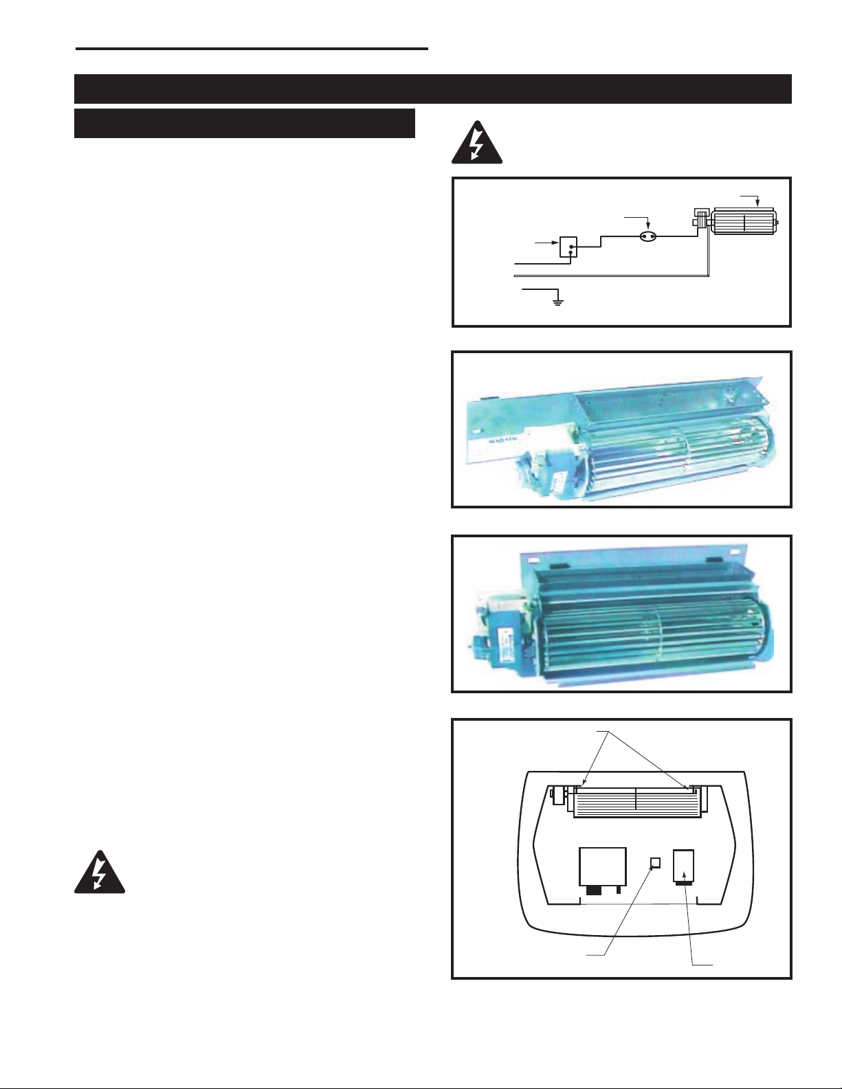
RFSDV24/34 Freestanding Direct Vent Gas Fireplace
Black
White
Ground
Optional Accessories
Fan Kits
FK24 Fan Assembly
This auxiliary fan system increases the efficiency of the
circulation of the heating air.
The FK24 fan kit allows variable speed control of the
circulation fan and also incorporates a heat sensor in
the circuit.
Specifications
115 Volt / 60Hz / 56 Watts
Maintenance
The fan itself does not require regular maintenance,
however periodic cleaning of the fan and the
surrounding area is required.
Check the fan and the area around the fan assembly
and wipe or vacuum at least once per month during the
operating season.
Installation
NOTE: The FK24 is an option for Model RFSDV24;
standard with model RFSDV34. Install fan before
connecting gas line to fireplace.
1. Open front access door; remove the cover valve.
2. Remove pre-mounted fan bracket at the rear of the
pedestal. Remember this location for reinstallation.
3. Open the fan kit; mount FK24 replacement fan
bracket. (Fig. 37)
4. Install the fan through the opening of the front
access door, with the outlet pointed up and the fan
mounting bracket toward the rear of the fireplace.
(Fig. 38) The fan mounts over two studs that hold
the fan just below the firebox floor. Secure the fan in
place with two nuts provided.
5. Locate the fan speed control/junction box on screw
studs located on the right side of the cover valve.
Tighten with nuts provided.
6. Install thermal sensor element on screw studs
located to the right of the gas valve below the burner
base.
7. Reinstall cover valve. Plug in grounded service cord
to a convenient wall receptacle.
This fan assembly is furnished completely
wired. It must be electrically connected and
grounded in accordance with local codes.
US installations: Follow local codes and the National
Electrical Code ANSI/NFPA No. 70.
Canadian installations: In the absence of local codes,
follow current CSA C22.1 Canadian Electrical Code.
Disconnect the power supply before
servicing the fan. Refer to Figure 35 for
rewiring replacement components.
Fan
Temperature Sensor
Speed Control
Fig. 35 FK24 fan wiring.
Fig. 36 FK24 fan with existing fan bracket.
Fig. 37 FK24 fan kit with replacement fan bracket.
Stud
Fan Sensor
FP1520
Fig. 38 FK24 fan installation.
Location
FP1025
FP1518
FP1519
Fan Speed
Control/Junction Box
10003550
31
Page 32

RFSDV24/34 Freestanding Direct Vent Gas Fireplace
Optional Gold Trim Kit
A decorative gold-plated window trim kit, Model
RFSDV24TKG is available for the RFSDV24 Freestanding Fireplace.
Kit contents:
(1) Gold-plated window trim
(4) Magnets
Installation Procedure
1. Unpack the kit and confirm all parts are present.
2. It is very important to remove all the protective plastic wrap from the gold window trim.
3. Attach the magnets to the trim. (Fig. 39)
4. Position trim against the fireplace window frame assembly. The trim is held in place by the magnets.
NOTE: Only gold cleaner is to be used for this
window trim. Do not use brass polish or household
cleaners, as these products will damage the trim.
Gold cleaner products can be obtained from any
fireplace dealer.
Clean gold trim with a soft clean cloth slightly
dampened with gold cleaner product. Buff with a
soft dry cloth.
Installation Procedure
1. Unpack the kit and confirm all parts are present.
2. It is very important to remove all the protective plas
tic wrap from the brass components
3. Attach the magnets to the trim. (Fig. 40)
4. Position trim against the fireplace window frame as
sembly. The trim will be held in place by the magnets.
5. Fit the brass rings in place around any visible vent
joints.
NOTE: Use only lemon oil to clean this window trim
as directed below. Lemon oil can be obtained from
supermarkets and hardware stores. Do not use
brass polish or household cleaners, as these products will damage the trim.
Clean brass trim with a soft clean cloth slightly
dampened with lemon oil. Buff with a soft dry cloth.
-
-
(2) Larger Radi of
the Trim are to be
‘Up’ after Installation
Magnets
FP1521
Fig. 39 RFSDV24TKG magnet locations.
Optional Brass Trim Kit
A decorative brass window trim kit, Model
RFSDV34TKA is available for the RFSDV34 Freestanding Fireplace.
Kit contents:
(1) Brass window trim
(8) Magnets
(3) Brass trim rings (for the vent pipe joints)
Place Magnets Here
FP1522
Fig. 40 RFSDV34TKA magnet locations.
Remote Control Options
These remote controls are available as an option only
on fireplaces fitted with RN/RP gas control valves.
Model Function Controlled
RC1 ON/OFF
RC2 ON/OFF and Temperature
MRC3 ON/OFF and Temperature control with
a digital display and a programmable
24 our clock
IMT Wall mounted thermostat control
32
10003550
Page 33

RFSDV24/34 Freestanding Direct Vent Gas Fireplace
10003550
33
Page 34

RFSDV24/34 Freestanding Direct Vent Gas Fireplace
34
10003550
Page 35

LIMITED LIFETIME WARRANTY
RFSDV24/34 Freestanding Direct Vent Gas Fireplace
PRODUCT COVERED BY THIS WARRANTY
All Vermont Castings gas stoves, gas inserts, and gas fireplaces, and all Majestic brand gas fireplaces equipped with
an Insta-Flame Ceramic Burner, or standard steel tube burner.
BASIC WARRANTY
CFM Corporation (hereinafter referred to collectively as the Company)
warrants that your new Vermont Castings or Majestic Gas Fireplace/
Stove is free from manufacturing and material defects for a period of
one year from the date of purchase, subject to the following conditions
and limitations.
EXTENDED LIFETIME WARRANTY
The heat exchanger, where applicable, and combustion chamber
of every Vermont Castings or Majestic gas product is warranted for
life against through wall perforation. All appliances equipped with an
Insta-Flame Ceramic Burner have limited lifetime coverage on the
ceramic burner plaque. Warrantees are made to the original owner
subject to proof of purchase and the conditions and limitations listed
on this Warranty Document
COMPONENT WARRANTY
CAST IRON: All external and internal cast iron parts are warranted for a
period of three years.
Note: On porcelain enamel finished external parts and accessories The
Company offers no Warranty on chipping of enamel surfaces. Inspect
all product prior to accepting it for any damage to the enamel.
The salt air environment of coastal areas or a high humidity environment
can be corrosive to the porcelain enamel finish. These conditions can
cause rusting of the cast iron beneath the porcelain enamel finish,
which will cause the finish to flake off.
Dye lot variations with replacement parts and/or accessories can occur
and are not covered by warranty.
GLASS DOORS: Glass doors are covered for a period of one year.
Glass doors are not warranted for breakage due to misuse or accident.
Glass doors are not covered for discoloration or burned in stains due to
environmental issues, or improper cleaning and maintenance.
BRASS PLATED PARTS AND ACCESSORIES: Brass parts should be
cleaned with Lemon oil only.
mix and masonry cleaners may corrode the brass finish. The Company
will not be responsible for, nor will it warrant any brass parts which are
damaged by external chemicals or down draft conditions.
GAS VALVES: Gas valves are covered for a period of one year
ELECTRONIC AND MECHANICAL COMPONENTS: Electronic and
mechanical components of the burner assembly are covered for one year.
All steel tube burners are warranted for one year.
ACCESSORIES: Unless otherwise noted all components and CFM
Corporation company supplied accessories are covered for a period of
one year.
CONDITIONS AND LIMITATIONS
• This new Vermont Castings or Majestic product must be installed by
a competent, authorized, service contractor. A licensed technician, as
prescribed by the local jurisdiction must perform any installation/service
work. It must be installed and operated at all times in accordance with
the Installation and Operating instructions furnished with the product.
Any alteration, willful abuse, accident, or misuse of the product shall
nullify this warranty.
• This warranty is non-transferable, and is made to the original owner,
provided that the purchase was made through an authorized supplier
of the Company.
• The customer must pay for any Authorized Dealer in-home travel fees
or service charges for in-home repair work. It is the dealers option
whether the repair work will be done in the customer’s home or in the
dealer’s shop.
• If upon inspection, the damage is found to be the fault of the manufacturer,
repairs will be authorized at no charge to the customer parts and/or
labor.
Brass cleaners cannot be used. Mortar
• Any part and/or component replaced under the provisions of this
warranty is covered for six months or the remainder of the original
warranty, whichever is longest.
• This warranty is limited to the repair of or replacement of part(s) found
to be defective in material or workmanship, provided that such part(s)
have been subjected to normal conditions of use and service, after
said defect is confirmed by the Company’s inspection.
• The company may, at its discretion, fully discharge all obligations
with respect to this warranty by refunding the wholesale price of the
defective part(s)
• Any installation, labor, construction, transportation, or other related
costs/expenses arising from defective part(s), repair, replacement,
or otherwise of same, will not be covered by this warranty, nor shall
the Company assume responsibility for same. Further, the Company
will not be responsible for any incidental, indirect, or consequential
damages except as provided by law.
• SOME STATES DO NOT ALLOW FOR THE EXCLUSION OR
LIMITATIONS OF INCIDENTAL AND CONSEQUENTIAL DAMAGES
OR LIMITATIONS ON HOW LONG AN IMPLIED WARRANTY
LASTS, SO THE ABOVE LIMITATIONS MAY NOT APPLY TO YOUR
CIRCUMSTANCES. THIS WARRANTY GIVES YOU SPECIFIC
RIGHTS AND YOU MAY HAVE OTHER RIGHTS WHICH VARY FROM
STATE TO STATE.
• All other warranties-expressed or implied- with respect to the product,
its components and accessories, or any obligations/liabilities on the
part of the Company are hereby expressly excluded.
• The Company neither assumes, nor authorizes any third party to
assume on its behalf, any other liabilities with respect to the sale of
this Vermont Castings or Majestic product
• The warranties as outlined within this document do not apply to
chimney components or other non CFM Corporation accessories used
in conjunction with the installation of this product..
• Damage to the unit while in transit is not covered by this warranty but
is subject to claim against the common carrier. Contact the dealer
from whom you purchased your fireplace/stove (do not operate the
appliance as this might negate the ability to process the claim with the
carrier).
• The Company will not be responsible for:
a) Down drafts or spillage caused by environmental conditions such
as near-by trees, buildings, roof tops, hills, or mountains.
b) Inadequate ventilation or negative air pressure caused by
mechanical systems such as furnaces, fans, clothes dryers, etc.
• This warranty is void if:
a) The fireplace has been operated in atmospheres contaminated by
chlorine, fluorine, or other damaging chemicals.
b) The fireplace has been subjected to prolonged periods of dampness
or condensation
c) Any damages to the fireplace, combustion chamber, heat exchanger
or other components due to water, or weather damage, which is the
result of but not limited to, improper chimney/venting installation.
d) Any alteration, willful abuse, accident, or misuse of the product
has occurred.
IF WARRANTY SERVICE IS NEEDED…
1) Contact your supplier. Make sure you have your warranty,
your sales receipt, and the model/serial number of your CFM
Corporation product.
2) D O NO T ATTEM P T T O DO A NY S E RVIC E WOR K
YOURSELF.
10003550
35
Page 36

Efficiency Ratings
Model EnerGuide Ratings
Fireplace Efficiency (%)
RFSDV24RN 65.3
RFSDV24RP 65.3
RFSDV24RFN 65.3
RFSDV24RFP 65.3
RFSDV24EN 68.7
RFSDV24EP 68.7
RFSDV34RN 72.1
RFSDV34RP 72.1
RFSDV34RFN 72.1
RFSDV34RFP 72.1
RFSDV34EN 75.2
RFSDV34EP 75.2
CFM Corporation
2695 Meadowvale Blvd. • Mississauga, Ontario, Canada L5N 8A3
800-668-5323 • www.cfmcorp.com
 Loading...