

Page 1
Free-Standing
Fireplaces
RFS22
RFS32
RFS42
Installation Instructions & Homeowner's Manual
WARNING! IF THE INFORMATION IN THIS MANUAL IS NOT FOLLOWED EXACTLY, A FIRE OR
EXPLOSION MAY RESULT CAUSING PROPERTY DAMAGE, PERSONAL INJURY OR LOSS OF LIFE.
FOR YOUR SAFETY
WHAT TO DO IF YOU SMELL GAS:
• Do not try to light any appliance.
• Do not touch any electric switch
• Do not use any phone in your building.
• Immediately call your gas supplier from
your neighbours phone. Follow the gas
suppliers instructions.
• If you cannot reach your gas supplier call
the fire department.
The Vermont Castings
Majestic Products Company
410 Admiral Blvd., Mississauga
Ontario, Canada L5T 2N1
www.majesticproducts.com / www.vermontcastings.com
INSTALLER: DO NOT DISCARD THIS MANUAL - LEAVE FOR HOMEOWNER
FOR YOUR SAFETY
DO NOT STORE
OR USE GASOLINE OR OTHER
FLAMMABLE VAPOURS AND LIQUIDS
IN THE VICINITY OF THIS OR ANY
OTHER APPLIANCE.
• Installation and service must be performed by a
qualified installer, Service agency or your gas
supplier.
10000834
11/01 Rev. 2
Page 2

TABLE OF CONTENTS
PLEASE READ THE INSTALLATION & OPERATING INSTRUCTIONS BEFORE USING APPLIANCE.
Thank you and congratulations on your purchase of a Majestic fireplace
IMPORTANT: Read all instructions and warnings carefully before starting installation. Failure to follow these
instructions may result in a possible fire hazard and will void the warranty.
Installation Instructions...................................................................................................... 3
Important Curing/Burn Information ....................................................................... 3
Locating Your Fireplace........................................................................................ 3
Clearance to Combustibles .................................................................................. 3
Fireplace Dimensions ........................................................................................... 4
Gas Specifications................................................................................................ 5
Preparation ........................................................................................................... 5
Gas Line Installation ............................................................................................. 5
Installation of Remote Switch for RN/RP gas valve.............................................. 6
Fan Kit .................................................................................................................. 6
General Venting Information ............................................................................................. 7
Common Flue Installation..................................................................................... 7
Retrofitting to an Existing Brick Chimney ............................................................. 8
Vent Safety System .............................................................................................. 8
Proper Vent Performance..................................................................................... 8
Combustion Air ..................................................................................................... 8
Operating Instructions ....................................................................................................... 9
General Glass Information.................................................................................... 9
Louvre Removal ................................................................................................... 9
Trim Removal ....................................................................................................... 9
Glass Removal ..................................................................................................... 9
Glass Cleaning ................................................................................................... 10
Installation of Logs and Burner Lava Rock......................................................... 10
Maintenance ....................................................................................................... 10
Cleaning Procedure............................................................................................ 11
Flame Adjustment & Characteristics .................................................................. 11
Ceramic Refractory............................................................................................. 11
Lighting Instructions............................................................................................ 12
Troubleshooting Gas Control (SIT 630).............................................................. 13
Troubleshooting Gas Control (SIT 820).............................................................. 14
Troubleshooting Gas Control (Honeywell).......................................................... 15
Replacement Parts List .............................................................................................. 16
Replacement Parts Pictorial ............................................................................... 17
Options 18
- 2 -
Page 3
INSTALLATION INSTRUCTIONS
This gas fireplace should be installed by a qualified installer in
accordance with local building codes and with current CAN /
CGA-B149 (. 1 or .2) Installation codes for Gas Burning
Fireplaces and Equipment.
FOR U.S.A Installations follow local codes and/or the current
National Fuel Gas Code. ANSI Z223.1.
FOR SAFE INSTALLATION AND OPERATION OF
YOUR MAJESTIC FIREPLACE PLEASE NOTE THE
FOLLOWING:
1. This fireplace gives off high temperatures and should
be located out of high traffic areas and away from
furniture and draperies.
2. Children and adults should be alerted to the hazards
of the high surface temperatures of this fireplace and
should stay away to avoid burns or ignition of clothing.
3. Children should be carefully supervised when they
are in the same room as your fireplace.
4. Under no circumstances should this fireplace be
modified. Parts removed for servicing should be
replaced prior to operating this fireplace again.
5. Installation and any repairs to this fireplace should be
carried out by a qualified service person. A professional service person should be contacted to inspect
this fireplace annually. Make it a practice to have all
of your gas fireplaces checked annually. More frequent cleaning may be required due to excess lint
and dust from carpeting, bedding material, etc.
6. Control compartments, burners and air passages in
this fireplace should be kept clean and free of dust
and lint. Make sure that the gas valve and pilot light
are turned off before you attempt to clean this fireplace.
7. The venting system(chimney) of this fireplace should
be checked at least once a year and if needed your
venting system should be cleaned.
8. Keep the area around your fireplace clear of combustible materials, gasoline and other flammable vapour
and liquids. This fireplace should not be used as a
drying rack for clothing, nor should Christmas stockings or decorations be hung in the area of it.
9. Under no circumstances should any solid fuels (wood,
coal, paper or cardboard etc.)be used in this fireplace.
10.The flow of combustion and ventilation air must not be
obstructed in any way.
11.When the fireplace is installed directly on carpeting,
vinyl tile or any combustible material other than wood,
the fireplace must be installed on a metal or wood
panel extending the full width and depth of the
fireplace.
12.This fireplace requires adequate ventilation and
combustion air to operate properly.
13.This fireplace must not be connected to a chimney
flue serving a separate solid fuel burning fireplace.
IMPORTANT:
PLEASE REVIEW THE FOLLOWING
CAREFULLY
Remove any plastic from trim parts before turning the
fireplace ON.
It is normal for fireplaces fabricated of steel to give off
some expansion and/or contraction noises during the
start up or cool down cycle. Similar noises are found
with your furnace heat exchanger or car engine.
It is not unusual for your Majestic gas fireplace to give
off some odour the first time it is burned. This is due
to the curing of the paint and any undetected oil from
the manufacturing process.
Please ensure that your room is well
ventilated - open all windows.
It is recommended that you burn your
for a least six (6) hours the first time you use it. If
optional fan kit has been installed, place fan in the
"OFF" position during this time.
Majestic
fireplace
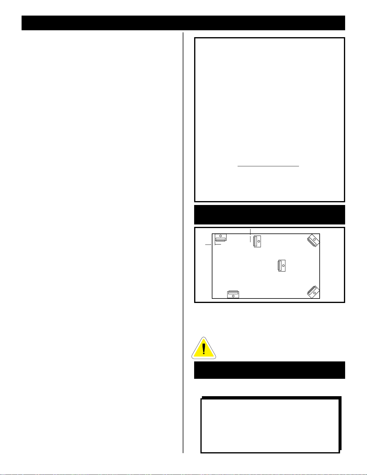
LOCATING YOUR MAJESTIC
GAS FIREPLACE
12" (305mm)
A
12" (305mm)
A) *Flat on wall corner B) *Room divider
C) Island D) Cross corner
E) Flat on wall
* A & B must maintain a 12" (305mm) clearance between the wall
and side glass of fireplace.
B
C
E
D
F
Fig. 1
A minimum 12 foot vent height is required
to effectively vent this fireplace.
CLEARANCES TO COMBUSTIBLES
Adequate clearances as listed below must be
maintained for servicing and proper operation.
BACK... ...................................... 1"
SIDES.. .................................... 12"
COMBUSTIBLE FLOOR............ 0"
TOP.......................................... 36"
CORNER ............ 0" to back edges
- 3 -
Flue Pipe Clearances - 6" Single Wall, 1"B" Vent.
Page 4
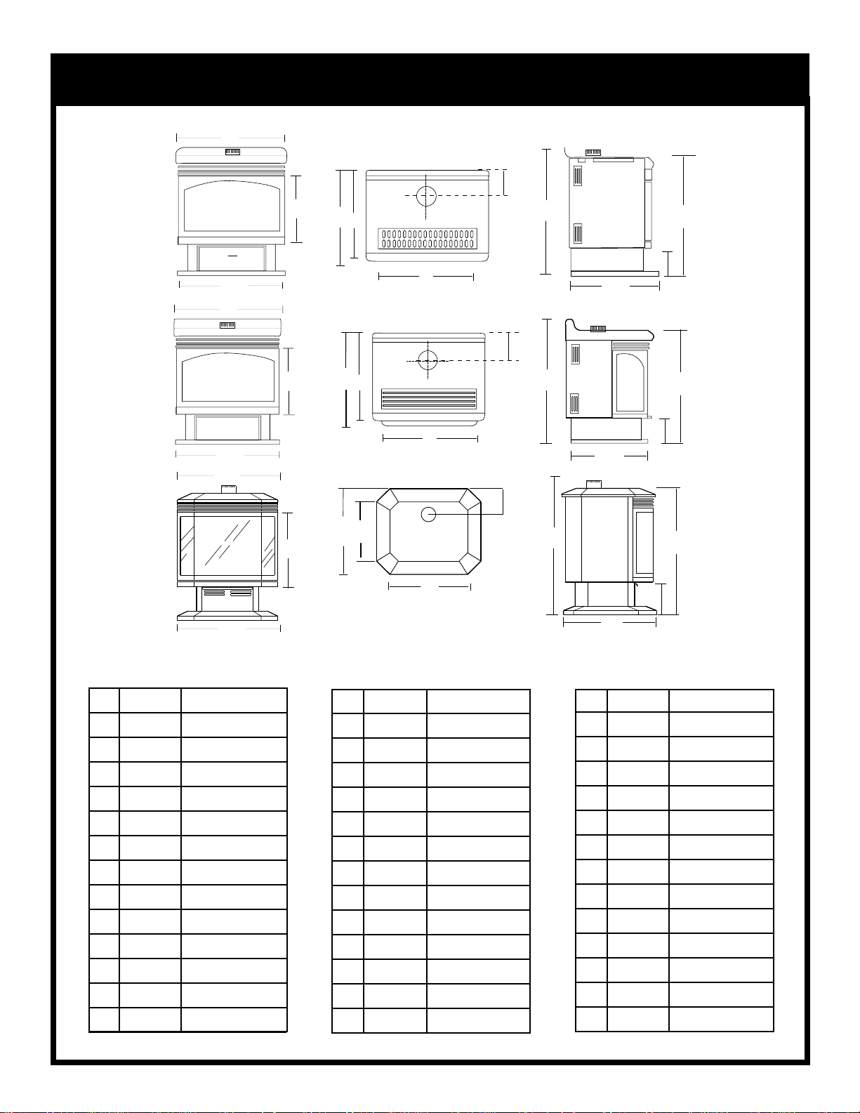
FIREPLACE DIMENSIONS
A
K
C
D
E
G
I
J
B
A
MODEL RFS22
F
H
K
C
B
A
D
E
F
MODEL RFS32
G
I
J
H
K
D
M
C
N
L
I
J
B
MODEL RFS22
A 26" 660mm
B 26" 660mm
5/8"
1/4"
1/4"
1/4"
5/8"
1/2"
3/4"
5/8"
387mm
488mm
473mm
800mm
451mm
752mm
244mm
133mm
C 15
D 19
E 18
F 21" 533mm
G 31
H 17
I 29
J9
K5
L– –
M– –
N– –
MODEL RFS42
MODEL RFS32
A 25" 635mm
1/4"
1/8"
3/4"
3/4"
5/8"
613mm
806mm
451mm
752mm
133mm
B 24
C 16" 406mm
D 20" 508mm
E 19" 483mm
F 21" 533mm
G 31
H 17
I 29
J 9" 229mm
K5
L– –
M– –
N– –
H
MODEL RFS42
1/4"
1/4"
1/4"
7/8"
3/4"
3/4"
5/8"
5/8"
3/8"
3/16
3/8"
717mm
717mm
454mm
578mm
578mm
854mm
270mm
133mm
924mm
360mm
441mm
A 28
B 28
C 17
D 22
E– –
F– –
G– –
H 22
I 33
J 10
K5
L 36
M14
N 17
- 4 -
Page 5
GAS SPECIFICATIONS
MAX. MIN.
MODEL FUEL GAS CONTROL B.T.U.H B.T.U.H.
RFS22RN Natural Gas Millivolt Hi/Lo 30,000 21,000
RFS22RP Propane Gas Millivolt Hi/Lo 30,000 22,500
RFS22TN Natural Gas Thermostatic 30,000 21,000
RFS22TP Propane Gas Thermostatic 30,000 22,500
RFS32RN Natural Gas Millivolt Hi/Lo 30,000 21,000
RFS32RP Propane Gas Millivolt Hi/Lo 30,000 22,500
RFS32TN Natural Gas Thermostatic 30,000 21,000
RFS32TP Propane Gas Thermostatic 30,000 22,500
RFS42RN Natural Gas Millivolt Hi/Lo 40,000 28,000
RFS42RP Propane Gas Millivolt Hi/Lo 37,000 27,750
RFS42TN Natural Gas Thermostatic 40,000 28,000
RFS42TP Propane Gas Thermostatic 37,000 27,750
INPUT INPUT
The installation of your Majestic Fireplace
must conform with local codes, or in the
absence of local codes, with National Fuel
Gas Code, ANSI Z223.1 latest edition, or CAN
1 B1-149.1 and .2 Installation Code.
(EXCEPTION: Do not derate this appliance
for elevations up to 4,500 ft. (1,370mm).
Maintain the manifold pressure at 3.5 inches
W.C. for Natural Gas and 10 inches W.C. for
LP gas.)
RFS22 / RFS32 / RFS42
CERTIFIED TO
ANSI.Z21.88a-1998 / CSA 2.33a - M98
Vented Gas Fireplace Heaters
GAS INLET & MANIFOLD PRESSURES
LP (Propane)
11" wc
13" wc
10" wc
Input Minimum
Input Maximum
Manifold Pressure
NATURAL
4.5" wc
7" wc
3.5" wc
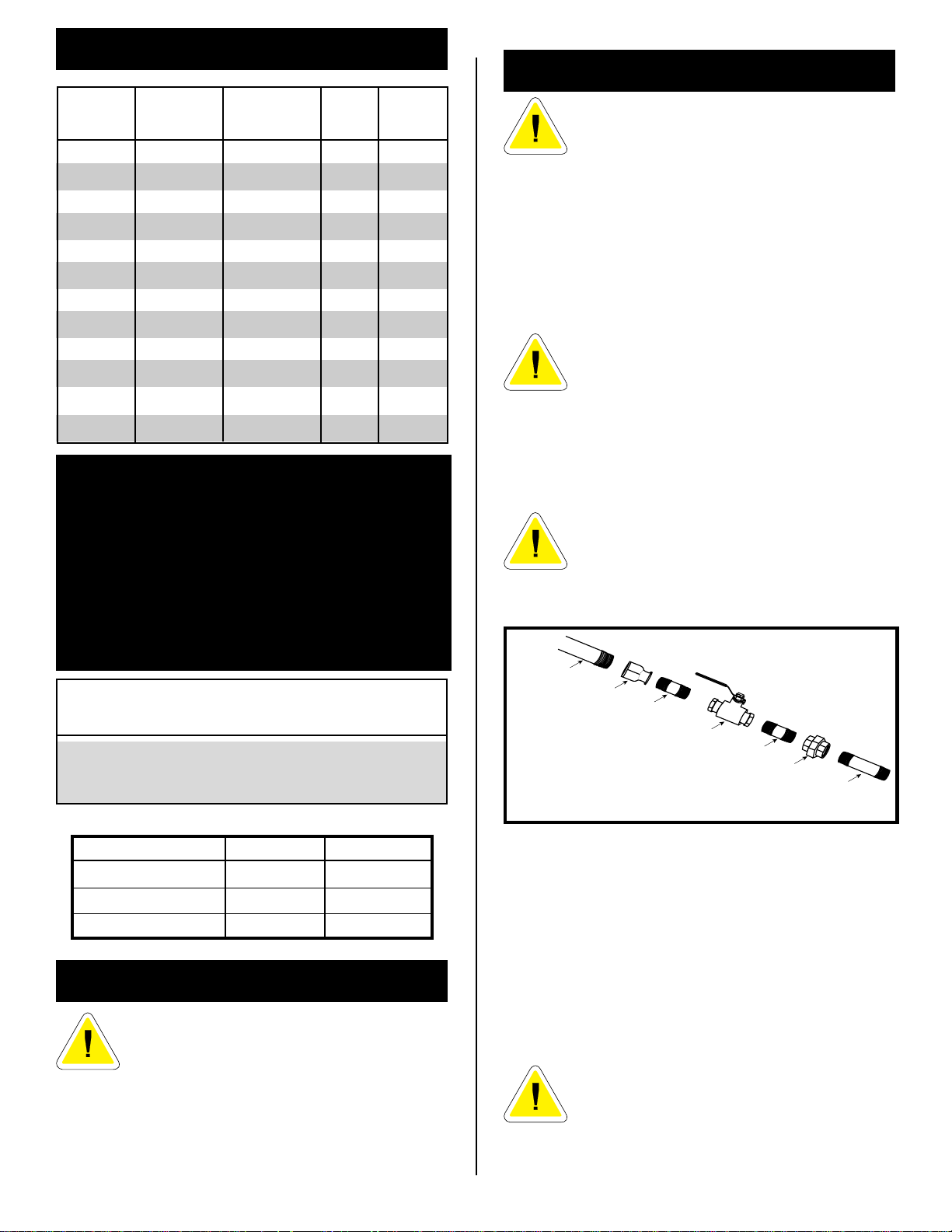
GAS LINE INSTALLATION
When purging gas line, the front glass must
be removed.
The gas pipeline can be brought in through the rear of the
fireplace as well as the bottom. Knockouts are provided on
the bottom behind the valve to allow for the gas pipe
installation and testing of any gas connection. It is most
convenient to bring the gas line in from the rear right
side of the valve, as this allows fan installation or
removal without disconnecting the gas line.
The gas line connection can be made with
properly tinned 3/8" copper tubing, 3/8" rigid
pipe or an approved flex connector. Since
some municipalities have some additional
local codes, it is always best to consult your
local authority and the CAN/CGA- B149 (.1 or
.2) installation code.
FOR U.S.A Installations consult the current National
Fuel Gas Code, ANSI Z223.1
Always check for gas leaks with a mild soap and
water solution. Do not use an open flame for
leak testing.
The gas control is equipped with a captured
screw type pressure test point, therefore it is not
necessary to provide a 1/8" test point up stream
of the control.
1/2" GAS SUPPLY
1/2" X 3/8" REDUCER
3/8" NIPPLE
3/8" X 3/8" SHUT OFF VALVE
3/8" NIPPLE
3/8" UNION
3/8" NIPPLE
Fig. 2 Typical gas supply installation
When using copper or flex connector use only approved
fittings. Always provide a union when using black iron
pipe so that gas line can be easily disconnected for burner
or fan servicing. See Fig. 2. See gas specification for
pressure details and ratings.
PREPARATION
The use of wall paper adjacent to this fireplace is not recommended, as the high heat
given off by this fireplace may adversely
effect the binders in the adhesive used to
apply the wallpaper.
Before beginning, remove the glass door from the fireplace
(See page 9). Also check to make sure there is no hidden
damage to the fireplace. Take a minute and plan out the
gas, vent and electrical supply.
The fireplace valve must not be subjected to any test
pressures exceeding 1/2 psi. Isolate or disconnect this or
any other gas appliance control from the gas line when
pressure testing.
DO NOT USE THIS FIREPLACE IF ANY PART
OF THIS FIREPLACE HAS BEEN UNDER
WATER. IMMEDIATELY CALL A QUALIFIED
SERVICE TECHNICIAN TO INSPECT THE
HEATER AND TO REPLACE ANY PART
CONTROL WHICH HAS BEEN UNDER
WATER.
- 5 -
Page 6
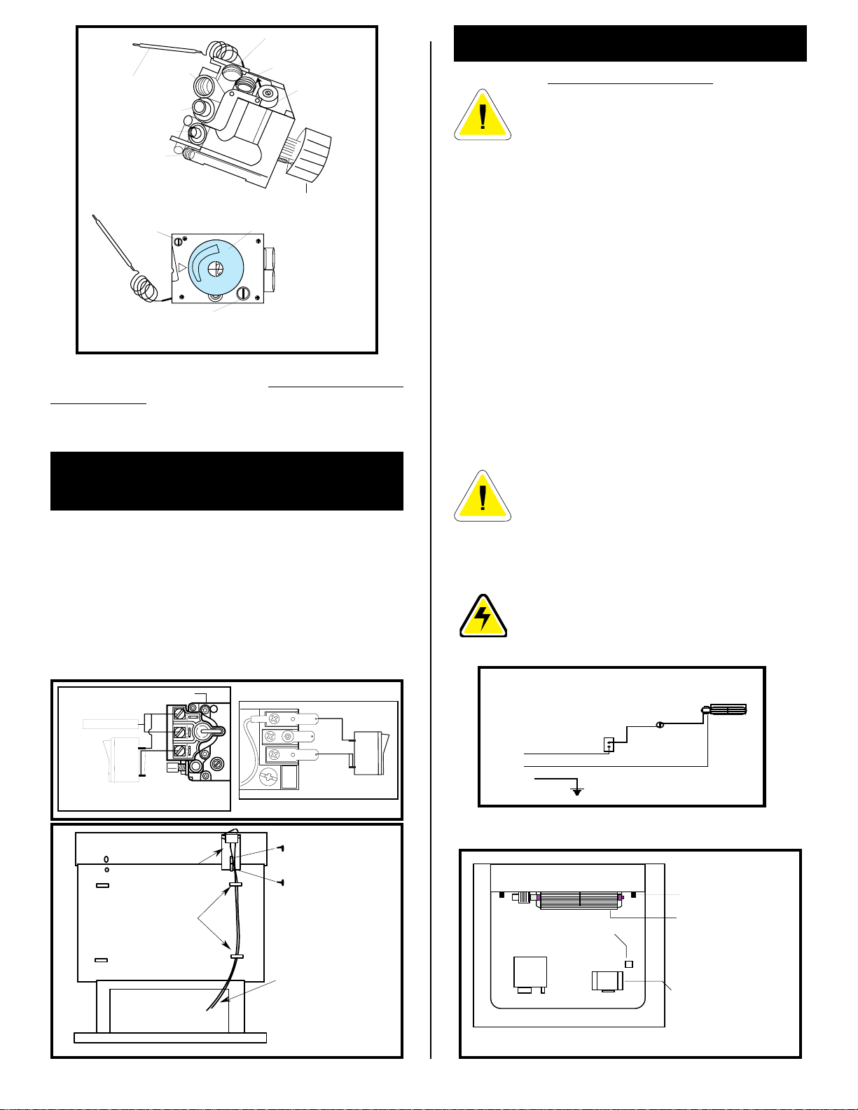
Manifold Gas Outlet
PILOT
ADJ
Thermostat
Bulb
Gas Inlet
Thermocouple
Inlet
Pilot Tube entry
Pilot Adjustment
Brass
Screw
Plug
Minimum
Rate Screw
(Non-Adjustable)
LO
Brass Plug
Pressure
Regulator
Control
Control
Knob
HI
it
OFF
PILOT
Knob
Fig. 3
On fireplaces equipped with Eurosit 630 gas valves there
are brass plugs in two of the holes. These plugs are not
to be removed. The gas inlet hole has a plastic cap in it.
Remove the plastic cap and connect your gas supply line
at this point. (Fig. 3).
INSTALLATION OF REMOTE
SWITCH FOR RN/RP GAS VALVE
Install on/off switch assembly on either the rear right or
left side of the RFS22/RFS32/RFS42 Gas Fireplace.
1. Remove the screw at the back of the cabinet top either
on the left or the right side of the fireplace.
2. Position switch assembly onto the back of the fireplace,
then fasten two screws as shown in Fig. 5.
3. Attach wiring under the clips on the rear casing (Fig. 5)
and install wiring through the rear opening of the
fireplace before connecting to the valve as shown in
Fig. 4.
VALVE
TPTH
THERMOPILE
ON/OFF SWITCH OR
MILLIVOLT THERMOSTAT
TP
TH
P
I
L
T
O
TP
Fig. 4
TH
TP
TH
OPTIONAL FAN KIT - FK24
STANDARD WITH RFS42
It will be easier to install the fan before
connecting the gas line to the fireplace.
1. Open front access door panel by pulling forward on
brass lip.
2. Guide the fan through the opening at the back of the
pedestal, with the outlet pointed up and the fan mounting
bracket facing the back of the fireplace. The fan mounts
over two studs which hold the fan just below the firebox
floor. Do not install this fan on the base. Hold the fan
in place with the two nuts provided. (Fig. 7)
3. Locate the fan speed control/junction box on screw
studs provided on base of the fireplace. Tighten with
3/8" nuts provided.
4. Install thermal sensor element on screw studs located
to the right of the gas valve on the burner base.
5. Plug in grounded service cord to a convenient wall
receptacle.
THIS FAN ASSEMBLY COMES COMPLETELY WIRED
TO ELIMINATE THE NEED FOR ELECTRICIANS. THIS
ELECTRICAL DEVICE, WHEN INSTALLED, MUST BE
ELECTRICALLY CONNECTED AND GROUNDED IN
ACCORDANCE WITH LOCAL CODES. IN THE ABSENCE
OF LOCAL CODES, WITH THE CURRENT CSA C22.1
CANADIAN ELECTRICAL CODE.
FOR U.S.A. INSTALLATION: FOLLOW LOCAL CODES
AND THE NATIONAL ELECTRICAL CODE ANSI/NFPA
NO.70-1984.
Should this fan require servicing, the power
supply must be disconnected. For rewiring of
any replacement components see Fig. 6.
A = Speed Control
B = Temperature Sensor
C = Fan
BLACK
WHITE
GROUND
B
A
C
Fig. 6
Screw
On/off switch
(through existing hole)
assembly
Clips
Screw
Wiring for milli-volt
gas valves
Fig. 5
Valve
TOP VIEW
Thermal sensor
location
Stud
Fan is installed at the back
of the pedestal
Fan speed control/
Junction box
Fig. 7
- 6 -
Page 7

VENTING INSTRUCTIONS
COMMON FLUE INSTALLATIONS
CANADIAN INSTALLATIONS:
The venting system must be installed in accordance with
the current CAN/CGA-B149 (.1 or.2) installation code, and
the authority having jurisdiction.
U.S.A. INSTALLATIONS:
The venting system must be installed in accordance with
the current National Fuel Gas Code, ANSI Z223.1.
Minimum clearances to combustible materials is 1 inch (25
mm) for B Vent (Fig. 9, 11) and 6 inches for single wall vent
(Fig. 10).
As with any natural drafted appliances, the vent cap must
always extend a minimum of 2' above any structure within
a 10' horizontal plane.(Fig. 8)
3'
10'
2'
10'
3'
In some areas it is possible to vent more than one gas
fireplace into the same flue. You must ensure that the flue
being shared has the proper capacity to handle both
fireplaces. Check installation codes for venting capacity
information.
As always it is best to check with the authority having
jurisdiction prior to commencement of the installation.
Fig. 9
Fig. 10
Fig. 8
VENTING OF THE RFS22/RFS32/RFS42
FIREPLACE
Note: Please refer to installation instructions supplied
by chimney manufacturer prior to commencing
installation.
The RFS22/RFS32/RFS42 may be installed using 4"
diameter single wall vent up to an existing masonry
chimney.(Fig. 10) This vent should then be connected to a
4" liner running the full height of the chimney, as it is
mandatory in most jurisdictions that the chimney be lined.
Another option is 4" "B" vent directly off the fireplace(Fig.9
& 11), going up to the chimney liner or up through the roof
if no chimney exists.
A minimum 12 foot vent height is required
to effectively vent this fireplace.
OFFSET B
VENT CHIMNEY
EXISTING
MASONRY CHIMNEY
Fig. 11
- 7 -
STRAIGHT B
VENT CHIMNEY
Page 8

Retrofitting To An Existing Brick Chimney
The CFM Majestic Products Company strongly recommends
installing an approved chimney liner in an existing brick
chimney.
This will maximize the potential draft of the chimney and
lessen the effects of slow chimney start up.
This is important because many homes (including older
renovated ones) have become much tighter with respect to
air exchange (a home breathing). An overly tight home will
create conditions that will affect proper vent performance.
PROPER VENT PERFORMANCE
Check
Draft
Here
It may be necessary to install some form of makeup air to
the lowest extremities of the home. This will help to ensure
the above noted condition will not effect the proper operation
of this or any other combustion fireplace within the dwelling.
VENT SAFETY SYSTEM
This fireplace is equipped with a vent safety shut down
switch. This switch is factory installed, wired and tested.
Check and make sure the switch and wires are in the proper
position. The safety switch is heat activated and wired in
series with the pilot system.
Operation of this fireplace when not
connected to a properly installed and
maintained venting system or tampering with
the vent safety shutoff system can result in
carbon monoxide (CO) poisoning and possibly
death.
Fig. 12
A spillage test must be performed prior to leaving the
fireplace with the customer. Carry this test out in the
following manner.
1) Close all windows and doors in the room; start all
exhaust fans in the house and furnace blower.
2) Light the fireplace and place in operation on high fire.
3) After several minutes, test with smoke match that there
is adequate "pull" at the draft hood opening (located on
the sides of the fireplace near back. See Figure 12)
If the flue is blocked (match being blown back into
room) the Vent Safety Switch will automatically shut
down the heater.
4) Should the heater turn off, wait approximately 10-15
minutes to allow for the switch to reset. Check draft
again. If the smoke is not drawn into the draft hood turn
the fireplace off and check the cause of lack of draft,
consult your dealer for expert advice.
COMBUSTION AIR
- 8 -
It is very important that an adequate air supply is available
when the unit is being operated. Since most homes of
today are tightly sealed and insulated, additional makeup air is usually necessary.
This fireplace has been designed to operate by drawing air
in from the front and outer perimeters of the fireplace. The
air provides combustion air ensuring a clean burning
flame, dilution air for proper venting, as well as, the air
which the fan circulates over the firebox/heat exchanger
system.
Insulating around the fireplace will result in overheating
and possible malfunctioning of the circulating fan.
Page 9

OPERATING INSTRUCTIONS
GENERAL GLASS INFORMATION
Only glass approved for use in The CFM
Majestic Products Company products
may be used for replacement.
1. The use of substitute glass will void all product
warranties.
2. Care must be taken to avoid breakage of the glass.
Under no circumstances should this fireplace
be operated without the front glass or with a
broken glass. Replacement of the glass (with
gasket) as supplied by the manufacturer
should be done by a licenced qualified
service person.
For the RFS42 both front bay window glass and
rear window glass need to be installed for
proper performance. Under no circumstance
should this fireplace be operated without the
rear window glass or with broken glass.
Replacement of the rear glass (with gasket) as
supplied by the manufacturer should be done
by a licensed qualified person.
LOUVRE REMOVAL
RFS22
Remove the front louvre assembly by lifting up and outward
on the assembly.
RFS32
To remove louvres first remove the two (2) screws (Fig. 13)
fastening the louvre assembly to the fireplace. Lift the
louvre assembly straight out sliding the back guides out of
the fireplace body. (To reinstall, reverse).
RFS42
The top louvre is assembled with the Bay Window Frame
and is not required to be removed.
Front View
Screws
Fig. 13
TRIM REMOVAL
RFS22
1. Remove frame window brass trim by lifting up and out.
2. Remove decorative cover, which was at the bottom of
the frame window trim by loosening two (2) nuts on the
underside of the cover.
RFS32
1. Remove the two (2) outer 3/8" nuts holding the frame
window brass trim in place. (Fig. 14)
2. Remove the frame window brass trim by moving it
straight forward.
RFS42
Remove trim Bay Window, top and bottom by pulling
them from the unit. They are held with magnets.
- 9 -
GLASS REMOVAL
RFS22
1. Remove frame window brass trim (See Trim Removal
section)
2. Remove remaining bottom 3/8" nut at the bottom of the
frame window.
3. Remove frame window by pulling it forward and up.
RFS32
1 . Remove frame window brass trim (See Trim Removal
section)
2. Remove remaining bottom 3/8" nut fat the bottom of
the frame window.
3. Remove 3/8" nut from each side of the frame window
(Fig. 14).
4. Remove frame window by pulling it forward and up.
GLASS
FRAME
OUTER NUTS
DRAWING 1
Side Nuts
BOTTOM NUT
RFS42
1 . Remove both Bay Window brass trims (See Trim
Removal section).
2. Open two clamps underneath the Bay Window that
holds the Bay Window Frame and Glass Frame. (Fig.
15)
3. Lift and unhook the Bay Window assembly at the top.
4. Lift and unhook the Glass Frame at the top.
WINDOW
FRAME
PULL
CLAMP HOOK
PUSH
CLAMP HANDLE
DRAWING 2
Fig. 14
Fig. 15
Page 10

GLASS CLEANING
It will be necessary to clean the glass periodically.
During start-up condensation, which is normal, forms on
the inside of the glass and causes lint, dust and other
airborne particles to cling to the glass surface. Also
initial paint curing may deposit a slight film on the glass.
It is therefore recommended that the glass be cleaned
two or three times with a non-ammonia household
cleaner and warm water (we recommend gas fireplace
glass cleaner). After that the glass should be cleaned
two or three times during each heating season
depending on the circumstances present.
Clean glass after first two weeks of
operation.
INSTALLATION OF LOGS &
BURNER LAVA ROCK
RFS22 & RFS32
RFS42
1 .Remove Bay Window assembly and Glass Frame (see
"Glass Frame Removal" section).
2. Remove logs from packaging.
3. Place rear log (SR4) on rear bracket . Ensure log is
seated properly, leveled and centered to the unit), so it
will not move from side to side and it is firmly positioned
on the bracket.
4. Slip front ember log (SR1) down in the front deflector.
5. Place front left log (SR2) on on top of burner, left side.
Use log's bottom holes to locate it into the left bracket log
locator studs.
6. Place front right log (SR3) on on top of burner,right side.
Use log's bottom holes to locate it into the right bracket
log locator studs.
7. Place burner lava rock on top of burner. (See Fig. 17 for
proper location).
8. Place top right log (SR6) onto locator notches. Ensure
log is secure.
9. Place top left log (SR5) onto locator notches. Ensure log
is secure.
1 . Remove front glass. (See "Glass Removal" section)
2. Remove logs from packaging.
3. Place rear log (KR4) on rear bracket (ensure log is
seated properly, leveled and centered to the unit), so it
will not move from side to side and it is firmly positioned
on the bracket.
4. Slip front ember log (KR1) down in the front deflector.
5. Place front left log (KR2) on top burner, left side. Use
log's bottom holes to locate it into the left bracket log
locator studs.
6. Place front right log (KR3) on top of burner, right side.
Use log's bottom holes to locate it into the right bracket
log locator studs.
7. Place small lava rocks and ember material on top of
burner. (See Fig. 16 for proper location).
8. Place top left log (KR5) onto locator notches. Ensure
log is secure.
9. Place top right log (KR6) onto locator notches. Ensure
log is secure.
Top logs must be placed properly into
notches
KR5
KR2
KR6
KR4
KR3
KR1
SR5
SR2
SR6
SR4
SR3
SR1
Fig. 17
Burner Lava Rock Placement
MAINTENANCE
1. It is important to keep the burner and the burner
compartment clean. This must be done periodically, at
least once per season. (See Cleaning Procedure).
2. Clean the brass trim using a soft clean cloth, slightly
dampened with lemon oil and buff with a soft clean
cloth. Do NOT use brass polish or household cleaners
as these products will damage the brass trim. Lemon
oil can be obtained at supermarkets or hardware
stores.
3. The optional FK24 Fan requires periodic cleaning.
Check the fan and the area around the fan assembly
and wipe or vacuum at least once per month during the
operating season.
4. Contact your local representative to arrange an annual
service program.
Burner Lava Rock Placement
Fig. 16
- 10 -
Page 11

CLEANING PROCEDURE
1. Turn off pilot light at gas valve.
2. Remove front glass.
3. Remove logs.
CAUTION: LOGS MAY BE HOT
3/8" - 1/2"
4. Vacuum burner compartment especially around orifice/
primary air openings.
5. Reinstall logs.
6. Check pilot and main burner operation.
7. Reinstall front glass.
8. Recheck pilot and main burner operation.
9. Check visually the flame pattern and compare with Fig.
21 or 22.
FLAME ADJUSTMENT (RN/RP MODELS)
For units equipped with Hi/Lo valves, flame adjustment
is accomplished by rotating the Hi/Lo adjustment knob
located near the centre of the gas control. (Fig. 18a & b)
I
H
Turn
counterclockwise
to increase
flame height.
Turn
counterclockwise
to decrease
flame height.
L
O
H
O
L
I
Turn clockwise
to lower
flame height.
Fig. 18a
Turn clockwise
to increase
flame height.
Fig. 18b
SIT VALVE PSE VALVE
Fig. 20
RFS22
RFS32
Fig. 21
RFS42
CERAMIC REFRACTORY
RFS42 ONLY
1. Remove bay window assembly and glass frame (see "Glass
frame Removal" section).
2. Remove logs from the unit.
LOGS MAY BE HOT
3. Remove refractory from packaging.
Refractory are fragile and must be handled with
care. Where at all possible, two hands should be
used when handling.
TEMPERATURE ADJUSTMENT
(TN/TP MODELS)
The Hi/Lo reference on the control knob (Fig. 19) is to
indicate a higher or lower temperature setting. This setting
controls the heat by reducing then
shutting off the flame as the desired
temperature is reached. Position
the control knob where it effectively
maintains a comfortable room
LO
HI
OFF
PILOT
temperature.
Fig. 19
FLAME CHARACTERISTICS
It is important to periodically perform a visual
check of the pilot and the burner flames.
Compare them to the pictorials illustrated
below
(Fig. 20, 21)
appear abnormal call a service person.
. If any of the flames
4. Take centre refractory piece and place it at the very back of
the firebox.
5. Take left or right side refractory and slide it along the side
of the firebox and on top of the bottom support channel. Be
sure to slide it back to hold the centre piece in place and the
leading edge faces forward.
6. Fasten top tab support against the refractory to hold it in
place.
7. Repeat steps 5 and 6 for remaining side refactory.
8. Insert refractory pieces into the Bay Window as per Fig. 23.
Leading
Edge
Left
Side
Centre
Right
Side
Leading
Edge
Fig. 22
Fig. 23
- 11 -
Page 12

LIGHTING AND OPERATING INSTRUCTIONS
it
P
I
L
O
T
OF
F
O
N
FOR YOUR SAFETY READ BEFORE LIGHTING
WARNING: If you do not follow these instructions exactly, a fire or explosion may result
causing property damage, personal injury or loss of life.
A . This fireplace has a pilot which must be lit manually.
When lighting the pilot follow these instructions exactly.
B. BEFORE LIGHTING smell all around the fireplace area for
gas. Be sure to smell next to the floor because some gas
is heavier than air and will settle on the floor.
WHAT TO DO IF YOU SMELL GAS
• Do not try to light any fireplace.
• Do not touch any electric switch
• Do not use any phone in your building
• Immediately call your gas supplier from a neighbor's
phone. Follow the gas supplier's instructions.
• If you cannot reach your gas supplier, call the Fire
Department
LIGHTING INSTRUCTIONS
1. STOP! Read the safety information above on this
label
2. Turn off all electrical power to the fireplace.
3. For MN/MP/TN/TP appliances ONLY, go on to Step 4.
For RN/RP appliances turn the On/Off switch to off
position or set thermostat to lowest level.
4. Open control access panel.
5. Push in gas control knob slightly and turn clockwise
to "OFF". Do not force.
OFF
LO
HI
OFF
PILOT
EURO SIT SIT NOVA HONEYWELL
6. Wait five (5) minutes to clear out any gas. Then smell
for gas, including near the floor. If you smell gas,
STOP! Follow "B" in the safety information above on
this label. If you don't smell gas, go to the next step.
7. Remove glass door before lighting pilot. (See Glass
Frame Removal in manual).
8. Visibly locate pilot by the main burner.
9. Turn knob on gas control counterclockwise
to "PILOT".
PILOT
ON
C . Use only your hand to push in or turn the gas control
knob. Never use tools. If the knob will not push in or turn
by hand, do not try to repair it, call a qualified service
technician. Applying force or any attempted repair may
result in a fire or explosion.
D . Do not use this fireplace if any part has been under water.
Immediately call a qualified service technician to inspect
the fireplace and to replace any part of the control system
and any gas control which has been under water.
10 . Push the control knob all the way in and hold.
Immediately light the pilot by repeatedly depressing
the piezo spark ignitor until a flame appears.
Continue to hold the control knob in for about one
(1) minute after the pilot is lit. Release knob and it
will pop back up. Pilot should remain lit. If it goes
out, repeat steps 5 through 8.
OR
• If knob does not pop up when released, stop and
immediately call your service technician or gas
supplier.
• If after several tries, the pilot will not stay lit, turn
the gas control knob to "OFF" and call your service
technician or gas supplier.
11. Replace glass door.
1 2. Turn gas control knob to "On" position.
13. For Rn/RP appliances turn the On/Off switch to "On"
positin or set thermostat to desired setting.
14. Turn on all electrical power to the fireplace.
TO TURN OFF GAS TO FIREPLACE
1. Turn the On/Off switch to Off position or set the
thermostat to lowest setting.
2. Turn off all electric power to the fireplace if service
is to be performed.
3. Open control access panel.
- 12 -
4. Push in gas control knob slightly
and turn clockwise to
"OFF". Do not force.
5. Close control access panel.
Page 13

TROUBLE SHOOTING THE GAS CONTROL SYSTEM
SIT 630 GAS VALVE
Note: Before trouble shooting the gas control system, be sure external gas shut off is in the "On" position.
WARNING: BEFORE DOING ANY GAS CONTROL SERVICE WORK, REMOVE GLASS FRONT.
SYMPTOM POSSIBLE CAUSES CORRECTIVE ACTION
1. Spark ignitor will not light A. Defective or misaligned Using a match, light pilot. If pilot lights, turn off pilot and
electrode at pilot. push the red button again. If pilot will not light - check gap
at electrode and pilot-should be 1/8" to have a strong spark.
B. Defective ignitor (Push Button) Push Piezo Ignitor Button. Check for spark at electrode and
pilot. If no spark to pilot, and electrode wire is properly
connected, replace ignitor.
2. Pilot will not stay lit after A. Defective pilot generator 1.Check pilot flame. Must impinge on thermocouple.
carefully following lighting thermocouple. Clean and or adjust pilot for maximum flame impingement
instructions. on thermocouple.
B. Defective automatic valve Turn valve knob to "Pilot". Maintain flow to pilot; millivolt
operator. meter should read greater than 10 mV. If the reading is
okay and the pilot does not stay on, replace the gas
valve. Note: An interrupter block (not supplied) must be
used to conduct this test.
3. Pilot burning, no gas to A. Sensing bulb not in proper Make sure sensing bulb is located in bracket on the lower
burner, Valve knob "ON". location. right hand side of fireplace.
B. Temperature sensing bulb Carefully examine sensing bulb and capillery tube for
damaged or tubing to bulb damage. If tubing is kinked, replace gas valve.
kinked
4. Frequent pilot outage A. Pilot flame may be too low Clean and/or adjust pilot flame for maximum flame
problem. or blowing (high) causing the impingement on thermocouple.
pilot safety to drop out.
B. Possible blockage of the vent Check the vent terminal for blockage.
terminal.
C. Loose connections to/from the Check wires on the vent safety switch at the draft hood relief
vent safety switch opening and at the junction block where the thermocouple
meets the gas valve.
- 13 -
Page 14

TROUBLE SHOOTING THE GAS CONTROL SYSTEM
SIT NOVA 820 MILLIVOLT VALVE
Note: Before trouble shooting the gas control system, be sure external gas shut off is in the "On" position.
WARNING: BEFORE DOING ANY GAS CONTROL SERVICE WORK, REMOVE GLASS FRONT.
SYMPTOM POSSIBLE CAUSES CORRECTIVE ACTION
1. Spark ignitor will not light A. Defective or misaligned Using a match, light pilot. If pilot lights, turn off pilot and
electrode at pilot. push the red button again. If pilot will not light - check gap
at electrode and pilot-should be 1/8" to have a strong spark.
B. Defective ignitor (Push Button) Push Piezo Ignitor Button. Check for spark at electrode and
pilot. If no spark to pilot, and electrode wire is properly
connected, replace ignitor.
2. Pilot will not stay lit after A. Defective pilot generator 1.Check pilot flame. Must impinge on thermocouple/
carefully following lighting (thermocouple), remote wall thermopile. Note: this pilot burner assembly utilizes both
instructions. switch. a thermocouple and a thermopile. The thermocouple
operates the main valve operation (On and Off). Clean
and or adjust pilot for maximum flame impingement on
thermopile and thermocouple.
B. Defective automatic valve Turn valve knob to "Pilot". Maintain flow to pilot; millivolt
operator. meter should read greater than 10 mV. If the reading is
okay and the pilot does not stay on, replace the gas
valve. Note: An interrupter block (not supplied) must be
used to conduct this test.
3. Pilot burning, no gas to A. Wall switch or wires Check wall switch and wires for proper connections. Jumper
burner, Valve knob "ON", defective. wire across terminals at wall switch, if burner comes on,
Wall Switch "ON". replace defective wall switch. If okay, jumper wires across
wall switch wires at valve, if burner comes on, wires are
faulty or connections are bad.
B. Thermopile may not be 1. Be sure wire connections from thermopile at gas valve
generating sufficient terminals are tight and thermopile is fully inserted into pilot
millivoltage. bracket.
2. One of the wall switch wires may be grounded. Remove
wall switch wires from valve terminals if pilot now stays lit,
trace wall switch wiring for ground. May be grounded to
fireplace or gas supply.
3. Check thermopile with millivolt meter. Take reading at
thermopile terminals of gas valve. Should read 250-300
millivolts (minimum 150) while holding valve knob depressed in pilot position and wall switch "Off". Replace
faulty thermopile if reading is below specified minimum.
C. Plugged burner orifice. Check burner orifices for debris and remove.
D. Defective automatic valve Turn valve knob to "On", place wall switch to "On" millivolt
operator. meter should read greater than 100 mV. If the reading is
okay and the burner does not come on, replace the gas
valve.
4. Frequent pilot flare outage A. Pilot flame may be too low Clean and/or adjust pilot flame for maximum flame
problem. or blowing (high) causing the impingement on thermopile and thermocouple.
pilot safety to drop out.
B. Vent safety shutdown. Check the vent system for blockage. Check all connections
on vent safety switch.
- 14 -
Page 15

TROUBLE SHOOTING THE GAS CONTROL SYSTEM
HONEYWELL MILLIVOLT VALVE
START
CHECK
• GAS SUPPLY ON
NO
• SUPPLY LINE HOOKED UP
• SHUTOFF VALVE OPEN
YES
PILOT LIGHTS WITH
PIEZO IGNITOR
YES
PILOT STAYS LIT
YES
NO
NO
• LOCKOUT HAS ENGAGED. WAIT
60 SECONDS AND TRY AGAIN.
• FOR SPARK AT ELECTRODE
WHILE DEPRESSING PIEZO
— 1/8" GAP TO
PILOT HOOD NEEDED.
• ALL WIRING CONNECTIONS
• REPLACE PIEZO IGNITOR
• FOR AIR IN THE LINES
• THERMOPILE NEEDS A
MINIMUM 325mV. ADJUST
PILOT FLAME HEIGHT.
• ALL WIRING CONNECTIONS.
• REPLACE THERMOPILE
• THERMOCOUPLE NEEDS A
MINIMUM OF 14mV.
• DEFECTIVE VALVE. TURN TO
PILOT, METER SHOULD READ
GREATER THAN 100 mV. IF
NOT, REPLACE.
PILOT LIGHTS MAIN
BURNER
YES
SYSTEM OK.
NO
• VALVE IS TURNED ON
• ON/OFF SWITCH IS NOT
TURNED ON. WATCH
FOR GROUNDED WIRES!
• THERMOPILE NEEDS A
MINIMUM 325mV.
• PLUGGED BURNER ORIFICE.
- 15 -
Page 16

REPLACEMENT PARTS LIST
DESCRIPTION RFS22 RFS32 RFS42
1. Log Set Complete 10000160 10000160 10000205
1a. Log Ember Front KR1 KR1 SR1
1b. Log Front Left KR2 KR2 SR2
1c. Log Front Right KR3 KR3 SR3
1d. Log Rear KR4 KR4 SR4
1e. Log Top Left KR5 KR5 SR5
1f. Log Top Right KR6 KR6 SR6
2. Burner Lava Rock (Package) 57897 57897 57897
3a. Burner with Tiles Nat. 10000198 10000198 10000866
3b. Burner with Tiles Prop. 57904 57904 10000867
4. Ceramic Tile (single) 57803 57803 57803
5a. Orifice Front Nat. SEE RATING PLATE FOR ORIFICE SIZE
5b. Orifice Front Prop. SEE RATING PLATE FOR ORIFICE SIZE
6a. Orifice Main Nat. SEE RATING PLATE FOR ORIFICE SIZE
6b. Orifice Main Prop. SEE RATING PLATE FOR ORIFICE SIZE
7a. Orifice Pilot SIT Nat. 54273 54273 54273
7b. Orifice Pilot SIT Prop. 54272 54272 54272
8a. Orifice Pilot PSE Nat. 10001822 10001822 10001822
8b. Orifice Pilot PSE Prop. 10001823 10001823 10001823
9a. Pilot Assembly SIT Nat. 54219 54219 54219
9b. Pilot Assembly SIT Prop. 54221 54221 54221
10a. Pilot Asssembly PSE Nat. 10001739 10001739 10001739
10b. Pilot Assembly PSE Prop. 10001740 10001740 10001740
11. Pilot SIT 10001295 10001295 10001295
12. Pilot w/ignitor and cable PSE 10001824 10001824 10001824
13. Pilot Tubing w/fittings 53211 53211 53211
14. Manifold Tubing w/fittings 57318 57318 57318
15. Thermocouple with Interrupter SIT 54912 54912 54912
16. Thermocouple with Interrupter PSE 10001828 10001828 10001828
17. Thermopile 53374 53374 53374
18. Electrode Ignitor w/cable SIT 52465 52465 52465
19. Ignitor Piezo SIT 52464 52464 50932
20. Ignitor Piezo Honeywell 2000062 2000062 2000062
21a. Valve SIT 820 Nat. 52677 52677 52677
21b. Valve SIT 820 Prop. 52678 52678 52678
22. Extension Knob Hi/Lo (RN/RP) 10000165 10000165 55162
23. Extension Knob (On/Off) SIT (RN/RP) 10000166 10000166 55163
24a. Valve Honeywell Nat. 10001782 10001782 10001782
24b. Valve Honeywell Prop. 10001759 10001759 10001759
25a. Valve Eurosit 630 Nat. 51844 51844 51844
25b. Valve Eurosit 630 Prop. 51845 51845 51845
26. Fan with Bracket 54103 54103 54103
27. Electrical Cord (6ft.) 51865 51865 51865
28. Fan Temperature Sensor 51704 51704 51704
29. Speed Control 51738 51738 51738
30. Speed Control Knob 51882 51882 51882
31. Glass with Gasket -Front 52035 52035 57581
32. Glass with Gasket - Side – 52032 –
33. Gasket Glass 57316 57316 57317
34. Glass Bay Window - Front – – 57477
35. Glass Bay Window - Sides – – 57478
36a. Frame Window - Left Side – 55110 –
36b. Frame Window - Right Side – 55111 –
37. Frame Window - Front 55109 55109 57584
38. Bay Window Assembly (w/glass) – – 57582
39. Trim Frame Window (PB) 53477 52027 57583
40. Trim Front Louvre (PB) 53455` – –
41. Top Louvre 57263 53977 –
42. Front Louvre Assembly 57260 57907 57585
43. Access Door with Handle 54048 52052 57586
44. Latch 52057 52057 52057
45. Remote Switch 53606 53606 53606
46. Remote Wire Harness with Terminals 57265 57265 57265
47. Vent Safety Switch 51866 51866 51866
48. Vent Safety Switch Wiring Harness 54849 54849 54849
49. Clamp Frame Window – – 54174
50. Ceramic Refractory Lining Kit (Not Shown) – – 10000846
51. Ceramic Refractory Bay (ONLY Bay Set) (Not Shown) – – 10000847
(1)
Top or Bottom With Magnets
- 16 -
(1)
Page 17

42
40
41
33
43
REPLACEMENT PARTS
42
44
31
33
38
32
49
14
22
23
30
39
34
35
39
43
9 a/b
4
29
3a/b
5/6a/b
11
18
15
17
13
19
7a/b
10 a/b
42
43
39
37
41
36 a/b
47
26
28
2
48
21a,b
#1 - COMPLETE LOG SET -- RFS22/RFS32
PILOT
OFF
it
HI
25a/b
1d
LO
12 17
8 a/b
16
27
46
OFF
PILOT
ON
ADJ
PILOT
24 a/b
1d
45
L
I
O
H
20
#1 COMPLETE LOG SET RFS42
39
40
1b
1e
1a
- 17 -
1f
1c
1e
1b
1f
1c
1a
Page 18

OPTION
REMOTE CONTROL
For units with RN/RP valves
MRC1 - On/Off Button Remote Control
MRC2 - Temperature Control Remote
MRC3 - Temperature Control w/digital display &
24 hour programmable clock
IMT - Wall Mounted Thermostat
S
- 18 -
 Loading...