

Page 1

VERSALINK™ WIRELESS GATEWAY (MODEL 327W)
USER GUIDE
030-300505 Rev. A 1 April 2007
Page 2

)
TABLE OF CONTENTS
User GuideVersaLink Wireless Gateway (Model 327W
1. PRODUCT DESCRIPTION ..................................................................................................................................4
2. SAFETY INSTRUCTIONS ................................................................................................................................... 4
3. REGULATORY INFORMATION ........................................................................................................................ 5
3.1 FCC Compliance Note...................................................................................................................................5
3.2 Canada Certification Notice...........................................................................................................................6
4. NETWORKING REQUIREMENTS .....................................................................................................................7
5. HARDWARE FEATURES.................................................................................................................................... 8
5.1 LED Indicators ..............................................................................................................................................8
5.2 Cable Connectors and Switch Locations .......................................................................................................9
5.3 Connector Descriptions .................................................................................................................................9
6. INSTALLING THE HARDWARE......................................................................................................................10
6.1 Installation Requirements ............................................................................................................................10
6.2 Before you begin..........................................................................................................................................10
6.3 Microfilters ..................................................................................................................................................10
6.4 Hardware Installations .................................................................................................................................11
7. ACCESSING VERSALINK ................................................................................................................................15
7.1 Logging on to VersaLink............................................................................................................................. 15
7.2 Changing the Password................................................................................................................................16
8. CONFIGURING YOUR BROADBAND CONNECTION .................................................................................19
8.1 Confirming Your DSL Connection..............................................................................................................19
8.2 Setting Up an Account Profile..................................................................................................................... 20
8.3 Connecting to the Internet............................................................................................................................25
8.4 Disconnecting from the Internet ..................................................................................................................26
9. SETTING UP MACINTOSH OS X..................................................................................................................... 28
9.1 Opening the System Preference Screen.......................................................................................................28
9.2 Choosing the Network Preferences..............................................................................................................28
9.3 Creating a New Location.............................................................................................................................29
9.4 Naming the New Location........................................................................................................................... 29
9.5 Selecting the Ethernet Configuration...........................................................................................................29
9.6 Checking the IP Connection ........................................................................................................................30
9.7 Accessing Your Router................................................................................................................................ 31
10. BASIC CONFIGURATION ................................................................................................................................32
11. MAIN (HOME PAGE).........................................................................................................................................33
11.1 My Gateway Panel.......................................................................................................................................34
11.2 My Network Panel.......................................................................................................................................34
11.3 Action Zone Panel .......................................................................................................................................35
12. WIRELESS SETTINGS.......................................................................................................................................36
12.1 Basic Security Settings ................................................................................................................................37
12.2 Advanced Security Settings.........................................................................................................................40
030-300505 Rev. A 2 April 2007
Page 3

)
User GuideVersaLink Wireless Gateway (Model 327W
13. MY NETWORK...................................................................................................................................................52
13.1 Network Status ............................................................................................................................................52
13.2 Network Connections ..................................................................................................................................56
14. FIREWALL SETTINGS......................................................................................................................................82
14.1 General Firewall Security Settings ..............................................................................................................82
14.2 Editing Firewall Security Rules...................................................................................................................83
14.3 Port Forwarding...........................................................................................................................................85
14.4 DMZ Host—Single IP Address Passthrough............................................................................................. 104
14.5 Remote Administration..............................................................................................................................108
14.6 Static NAT.................................................................................................................................................111
14.7 Security Log ..............................................................................................................................................114
15. ADVANCED......................................................................................................................................................116
15.1 Diagnostics ................................................................................................................................................117
15.2 Restore Defaults.........................................................................................................................................120
15.3 Reboot Gateway.........................................................................................................................................121
15.4 Users .......................................................................................................................................................... 122
15.5 QOS ...........................................................................................................................................................123
15.6 Remote Administration..............................................................................................................................124
15.7 ATM Loopback .........................................................................................................................................125
15.8 Detect WAN Configuration.......................................................................................................................127
15.9 DNS Server................................................................................................................................................ 129
15.10 Configuration File..................................................................................................................................132
15.11 Firmware Upgrade.................................................................................................................................133
15.12 Universal Plug and Play.........................................................................................................................136
15.13 Routing ..................................................................................................................................................137
15.14 IP Address Distribution .........................................................................................................................138
15.15 Private LAN—Configuring NAT ..........................................................................................................141
15.16 Public LAN—Multiple IP Address Passthrough ...................................................................................142
15.17 VLAN Configuration............................................................................................................................. 145
15.18 RIP Configuration.................................................................................................................................. 147
16. SYSTEM MONITORING..................................................................................................................................149
16.1 Gateway Status .......................................................................................................................................... 150
16.2 Advanced Status ........................................................................................................................................151
17. PORT FORWARDING SERVICES ...................................................................................................
18. TECHNICAL SUPPORT INFORMATION......................................................................................................167
19. PRODUCT SPECIFICATIONS.........................................................................................................................167
20. SOFTWARE LICENSE AGREEMENT............................................................................................................ 168
21. PUBLICATION INFORMATION.....................................................................................................................170
030-300505 Rev. A 3 April 2007
...............163
Page 4

)
1. PRODUCT DESCRIPTION
User GuideVersaLink Wireless Gateway (Model 327W
The Verizon
office phone line and is capable of data rates hundreds of times faster than a traditional analog modem. But unlike
analog modems, the VersaLink Gateway allows you to use the same phone line for simultaneous voice/fax
communications and high-speed Internet access, eliminating the need for dedicated phone lines for voice and data
needs. In addition, VersaLink supports a variety of networking interfaces such as Wireless 802.11b/g, ADSL,
Ethernet and the following optional features:
• UPLINK/E1: Alternate WAN uplink port
• Layer w/2 QOS with VLAN tagging
• HotSpot
• Simultaneous public/private network support
Hereafter, the Verizon® VersaLink™ Wireless Gateway will be referred to as “VersaLink,” “Router,” or “Modem.”
®
VersaLink™ Wireless Gateway provides reliable, high-speed, Internet access to your existing small
2. SAFETY INSTRUCTIONS
• Never install any telephone wiring during a lightning storm.
• Never install telephone jacks in wet locations unless the jack is specifically designed for wet locations.
• Never touch non-insulated telephone wires or terminals unless the telephone line has been disconnected at
the network interface.
• Use caution when installing or modifying telephone lines.
WARNING
Risk of electric shock. Voltages up to 140 Vdc (with reference to
ground) may be present on telecommunications circuits.
030-300505 Rev. A 4 April 2007
Page 5

)
User GuideVersaLink Wireless Gateway (Model 327W
3. REGULATORY INFORMATION
3.1 FCC Compliance Note
(FCC ID: CH8D90327WXXX-06)
This equipment has been tested and found to comply with the limits for a Class B digital device, pursuant to Part 15
of the Federal Communication Commission (FCC) Rules. These limits are designed to provide reasonable protection
against harmful interference in a residential installation. This equipment generates, uses, and can radiate radio
frequency energy, and if not installed and used in accordance with the instructions, may cause harmful interference
to radio communications. However, there is no guarantee that interference will not occur in a particular installation.
If this equipment does cause harmful interference to radio or television reception, which can be determined by
turning the equipment OFF and ON, the user is encouraged to try to correct the interference by one or more of the
following measures:
• Reorient or relocate the receiving antenna.
• Increase the separation between the equipment and the receiver.
• Connect the equipment to a different circuit from that to which the receiver is connected.
• Consult the dealer or an experienced radio/TV technician for help.
• This device complies with part 15 of the FCC Rules. Operation is subject to the following two conditions:
(1) this device may not cause harmful interference, and (2) this device must accept any interference
received, including interference that may cause undesired operation.
WARNING: While this device is in operation, a separation distance of at least 20 cm (8 inches) must be maintained
between the radiating antenna and users exposed to the transmitter in order to meet the FCC RF exposure guidelines.
Making changes to the antenna or the device is not permitted. Doing so may result in the installed system exceeding
RF exposure requirements. This device must not be co-located or operated in conjunction with any other antenna or
radio transmitter. Installers and end users must follow the installation instructions provided in this guide.
Modifications made to the product, unless expressly approved, could void the users’ rights to operate the
equipment.
PART 68 – COMPLIANCE REGISTRATION
This equipment is designated to connect to the telephone network or premises wiring using a compatible modular
jack that is Part 68 compliant. A FCC compliant telephone cord and modular plug is provided with the equipment.
See the Installation Information section of this User Guide for details.
A plug and jack used to connect this equipment to the premises wiring and telephone network must comply with the
applicable FCC Part 68 rules and requirements adopted by the ACTA. A compliant telephone cord and modular plug
is provided with this product. It is designed to be connected to a compatible modular jack that is also compliant. See
installation instruction for details.
If this terminal equipment (Model 327W) causes harm to the telephone network, the telephone company may
request you to disconnect the equipment until the problem is resolved. The telephone company will notify you in
advance if temporary discontinuance of service is required. If advance notification is not practical, the telephone
company will notify you as soon as possible. You will be advised of your right to file a complaint with the FCC if
you believe such action is necessary. If you experience trouble with this equipment (Model 327W), do not try to
repair the equipment yourself. The equipment cannot be repaired in the field. Contact Verizon for instructions.
030-300505 Rev. A 5 April 2007
Page 6
)
User GuideVersaLink Wireless Gateway (Model 327W
The telephone company may make changes to their facilities, equipment, operations, or procedures that could affect
the operation of this equipment. If this happens, the telephone company will provide advance notice in order for you
to make the modifications necessary to maintain uninterrupted service.
If your home has specially wired alarm equipment connected to the telephone line, ensure that the installation of this
equipment (Model 327W) does not disable your alarm equipment. If you have questions about what will disable
alarm equipment, consult your telephone company or a qualified installer.
This equipment cannot be used on public coin phone service provided by the telephone company. Connection of this
equipment to party line service is subject to state tariffs.
3.2 Canada Certification Notice
The Industry Canada label identifies certified equipment. This certification means that the equipment meets certain
telecommunications network protective, operations and safety requirements as prescribed in the appropriate
Terminal Equipment Technical Requirements document(s). The department does not guarantee the equipment will
operate to the user’s satisfaction.
This equipment meets the applicable Industry Canada Terminal Equipment Technical Specification. This is
confirmed by the registration number. The abbreviation, IC, before the registration number signifies that registration
was performed based on a Declaration of Conformity indicating that Industry Canada technical specifications were
met. It does not imply that Industry Canada approved the equipment. The Ringer Equivalence Number (REN) is 0.0.
The Ringer Equivalence Number that is assigned to each piece of terminal equipment provides an indication of the
maximum number of terminals allowed to be connected to a telephone interface. The termination on an interface
may consist of any combination of devices subject only to the requirement that the sum of the Ringer Equivalence
Numbers of all the devices does not exceed five.
Before installing this equipment, users should ensure that it is permissible to be connected to the facilities of the
local Telecommunication Company. The equipment must also be installed using an acceptable method of
connection. The customer should be aware that compliance with the above conditions may not prevent degradation
of service in some situations. Connection to a party line service is subject to state tariffs. Contact the state public
utility commission, public service commission, or corporation commission for information.
If your home has specially wired alarm equipment connected to the telephone line, ensure that the installation of this
equipment (Model 327W) does not disable your alarm equipment. If you have questions about what will disable
alarm equipment, consult your telephone company or a qualified installer.
If you experience trouble with this equipment (Model 327W), do not try to repair the equipment yourself. The
equipment cannot be repaired in the field and must be returned to the manufacturer. Repairs to certified equipment
should be coordinated by a representative, and designated by the supplier. Contact Verizon for instructions.
The termination on an interface may consist of any combination of devices subject only to the requirement that the
sum of the Ringer Equivalence Numbers of all the devices does not exceed five.
Users should ensure, for their own protection, that the electrical ground connections of the power utility, telephone
lines, and internal, metallic water pipe system, if present, are connected together. This precaution may be
particularly important in rural areas.
Users should not attempt to make such connections themselves, but should contact the
appropriate electrical inspection authority, or electrician, as appropriate.
030-300505 Rev. A 6 April 2007
CAUTION
Page 7
)
User GuideVersaLink Wireless Gateway (Model 327W
4. NETWORKING REQUIREMENTS
The following system specifications are required for optimum performance of the Router via 10/100 Base-T
Ethernet or USB installations.
Connection Type Minimum System Requirements
® or equivalent class machines or higher
® Windows® (Vista™, XP, 2000, ME, NT 4.0, 98 SE)
® OS X, or Linux installed
® or equivalent class or higher machines
® Windows® (Vista™,XP, 2000, ME, NT 4.0, 98 SE) or
ETHERNET
(UPLINK/E1, E2, E3, E4)
WIRELESS
IEEE 802.11b/g
• Pentium
• Microsoft
Macintosh
• 64 MB RAM (128 MB recommended)
• 10 MB of free hard drive space
• 10/100 Base-T Network Interface Card (NIC)
• Internet Explorer 5.5 or later or Netscape Navigator 7.x or later
• Computer Operating System CD-ROM on hand
• Pentium
• Microsoft
Macintosh® OS X installed
• 64 MB RAM (128 MB recommended)
• 10 MB of free hard drive space
• Internet Explorer 5.5 or Netscape Navigator 7.x or later
• An available IEEE 802.11b/g PC adapter
• Computer Operating System CD-ROM on hand
030-300505 Rev. A 7 April 2007
Page 8

)
User GuideVersaLink Wireless Gateway (Model 327W
5. HARDWARE FEATURES
5.1 LED Indicators
This section explains the LED States and Descriptions. LED indicators are used to verify the unit’s operation and
status.
LED States and Descriptions
LED State Description
Router power is ON.
Router power is OFF.
POST (Power On Self Test), Failure (not bootable) or Device
Malfunction. Note: The Power LED should be red no longer than
two seconds after the power on self test passes.
Powered device is connected to the associated port (includes
devices with wake-on LAN capability where slight voltage is
supplied to an Ethernet connection).
Note: When using the optional uplink port (E1), Ethernet LAN
connection is limited to E2, E3, and E4.
10/100 Base-T LAN activity is present (traffic in either direction)
Router power is OFF, no cable or no powered device is connected
to the associated port.
Link Established.
Wireless LAN activity is present (traffic in either direction).
Router power is OFF or No Link.
Good DSL link.
DSL attempting to sync.
Modem is in safeboot mode.
Router power is OFF.
Internet link established. With DSL up, the Router has a WAN IP
address from IPCP or DHCP; or a static IP is configured; or PPP
negotiation has successfully completed (if used) and no traffic is
detected.
IP connection established and IP Traffic is passing through device
(in either direction). Note: If the IP or PPP session is dropped due
to an idle timeout, the light will remain solid green, if an ADSL
connection is still present. If the session is dropped for any other
reason, the light is turned OFF. The light will turn red when it
attempts to reconnect and DHCP or PPP fails).
Device attempted to become IP connected and failed (no DHCP
response, no PPP response, PPP authentication failed, no IP
address from IPCP, etc.).
Router power is OFF, Router is in Bridge Mode, or the ADSL
connection is not present.
POWER
E1, E2, E3, E4
(Ethernet LAN)
WIRELESS
DSL
INTERNET
Solid Green
OFF
Solid Red
Solid Green
Flashing Green
OFF
Solid Green
Flashing Green
OFF
Solid Green
Flashing Green
Solid Amber
OFF
Solid Green
Flashing Green
Solid Red
OFF
030-300505 Rev. A 8 April 2007
Page 9
)
(
)
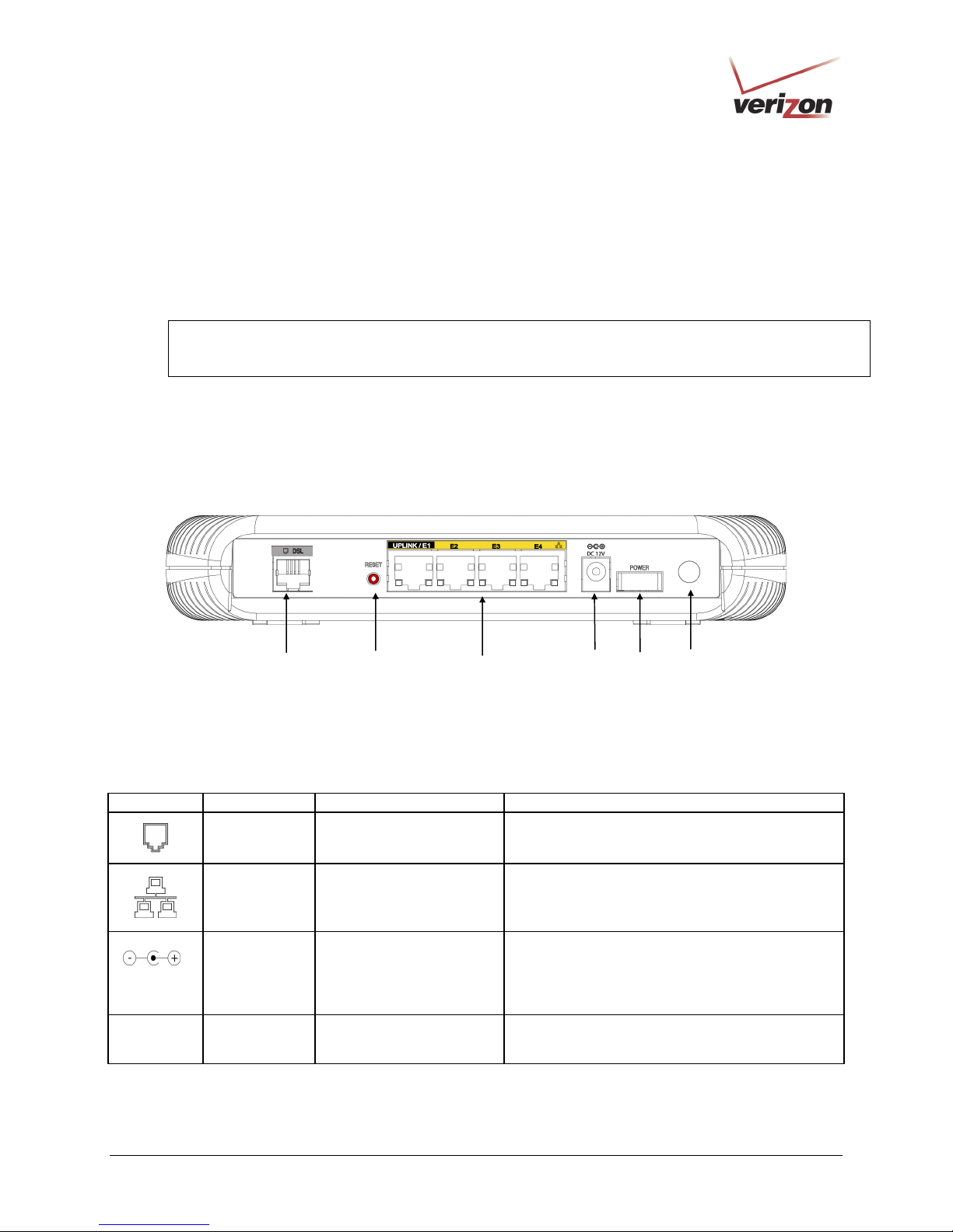
5.2 Cable Connectors and Switch Locations
• DSL connector (RJ-11)
• Reset push button
• (4) Ethernet connectors (RJ-45) optional uplink port
• (4) Ethernet connector (RJ-45) with optional UPLINK/E1 uplink port
NOTE: When using the optional UPLINK/E1 jack (when VersaLink is configured for WAN Uplink mode),
Ethernet LAN connection is limited to ports E2, E3, and E4. The Uplink feature is optional. If Uplink is not
enabled via the Web pages, VersaLink will use DSL as the WAN interface.
• Power connector (DC 12V) barrel
• OFF/ON power switch
• Wireless 802.11b/g SMA connector and antenna
VersaLink Gateway - Rear View
User GuideVersaLink Wireless Gateway (Model 327W
DSL Line
Connector
Reset
Button
Ethernet Connectors
UPLINK/E1 through E4
Power
Connector
Off/On
Power Switch
5.3 Connector Descriptions
The following chart displays the Router’s connector types.
SYMBOL NAME TYPE FUNCTION
DC 12V
Wireless
DSL LINE 6-pin (RJ-11) modular jack
ETHERNET 8-pin (RJ-45) modular jack
POWER Barrel connector
Antenna
SMA connector and
antenna
Connects to an ADSL-equipped telephone jack or
to the DSL connection of a POTS splitter.
Connects the 10/100 Base-T Ethernet device to a
PC or Hub.
Connects the DC 12V power connector to an AC
wall jack.
Connects via wireless 802.11 b/g
Wireless Antenna
Connector
030-300505 Rev. A 9 April 2007
Page 10
)
User GuideVersaLink Wireless Gateway (Model 327W
6. INSTALLING THE HARDWARE
This section explains the hardware installation procedures for connecting to your Router.
6.1 Installation Requirements
To install the VersaLink, you will need the following:
• Active DSL line
• Network Interface Card (NIC) installed in your PC, or
• 802.11 b/g wireless adapter
IMPORTANT: Please wait until you have received notification from your Internet service provider (ISP) that your
DSL line has been activated before installing your VersaLink.
6.2 Before you begin
Make sure that your kit contains the following items:
• Verizon VersaLink Wireless Gateway
• Power Supply
• RJ-45 Ethernet cable (straight-through) (yellow)
• RJ-11 Phone cable
• Verizon CD-ROM containing User Guide in PDF format
• Wireless antenna
6.3 Microfilters
ADSL signals must be blocked from reaching each telephone, answering machine, fax machine, computer Modem
or any similar conventional device. Failure to do so may degrade telephone voice quality and ADSL performance.
Install a microfilter if you desire to use the DSL-equipped line jack for telephone, answering machine, fax machine
or other telephone device connections. Microfilter installation requires no tools or telephone rewiring. Just unplug
the telephone device from the baseboard or wall mount and snap in a microfilter, next snap in the telephone device.
You can purchase microfilters from your local electronics retailer, or contact the original provider of your DSL
equipment.
030-300505 Rev. A 10 April 2007
Page 11
)
User GuideVersaLink Wireless Gateway (Model 327W
6.4 Hardware Installations
The following instructions explain how to install your VersaLink Gateway using 10/100 Base-T Ethernet, Wireless,
or Ethernet Uplink connections. Before you begin, please read the following notes:
NOTE:
1. If your Ethernet card does not auto-negotiate, set it to half duplex. Refer to the Ethernet card manufacturer’s
instructions for installing and configuring your Ethernet card.
2. If you are using VersaLink in conjunction with an Ethernet Hub or Switch, refer to the manufacturer’s
instructions for proper installation and configuration.
3. When using a Microfilter, confirm that the DSL RJ-11 phone cable is connected to the DSL port of the DSL/HPN
non-filtered jack.
4. It is recommended that you use a surge suppressor to protect equipment attached to the power supply. Use only
the power supply provided with your kit.
5. Additional Ethernet cables may be required depending on the installation method you are using. Ethernet cables
and filters can be purchased at your local computer hardware retailer.
6. VersaLink supports simultaneous use of 10/100 Base-T Ethernet and Wireless configurations. To use this
installation method, follow the instructions provided in sections 6.4.1 and 6.4.2.
VersaLink supports two modes for WAN access, which are configurable through VersaLink’s Web pages: (1) LAN
Ethernet port mode and (2) WAN Uplink port mode.
• LAN Ethernet port mode allows you to use VersaLink’s DSL port for WAN access (VersaLink’s DSL
functionality is Enabled). In this mode you should install VersaLink according to the instructions in the
following sections:
• Section 6.4.1, Connecting VersaLink via 10/100 Base-T Ethernet
• Section 6.4.2, Connecting VersaLink via Wireless
• WAN Uplink port mode allows you to use VersaLink as an Ethernet Gateway (for example, to connect to
a cable modem or to another ADSL device that provides WAN access). In WAN Uplink port mode,
VersaLink’s DSL functionality is Disabled. In this mode you should install VersaLink according to the
instructions in section 6.4.3, “Connecting VersaLink via UPLINK/E1.”
030-300505 Rev. A 11 April 2007
Page 12
)
User GuideVersaLink Wireless Gateway (Model 327W
6.4.1 Connecting VersaLink via 10/100 Base-T Ethernet
To connect your VersaLink using the 10/100-BaseT Ethernet connection, please follow these steps:
1. Connect the DSL phone cable from the connector marked DSL on the rear panel of VersaLink to the telephone
line jack (equipped with DSL service) on the wall. Please use the DSL phone cable that was provided with your
kit.
IMPORTANT: If you use a microfilter, you must plug the RJ-11 DSL phone cable from the VersaLink into the
DSL port of the microfilter.
2. Connect the yellow Ethernet cable (provided with your kit) from any one of the four Ethernet jacks marked E1,
E2, E3, or E4 on the rear panel of VersaLink to the Ethernet port on your computer. Repeat this step to connect
up to three additional PCs to VersaLink; each jack serves as an Ethernet switch.
3. Connect the power supply cord to the power connector marked DC 12V on the rear panel of the VersaLink. Plug
the other end of the power supply into an AC wall socket, and then turn on VersaLink (if it is not already on).
4. Check to see if the VersaLink’s POWER LED is solid green. This indicates that VersaLink is powered on.
5. Check to see if the DSL LED is solid green. If the DSL LED is solid green, the VersaLink is functioning
properly.
6. Check to see if the ETHERNET LED is solid green. Solid green indicates that the Ethernet connection is
functioning properly. Check the ETHERNET LED for the Ethernet jack you are using on VersaLink.
7. After you have logged on to your account and established an Internet connection, as explained later in section 8,
check to see if the Router’s INTERNET LED is solid green. Solid green indicates that an Internet link has been
established. (Flashing green indicates the presence of IP traffic.)
Congratulations! You have completed the Ethernet hardware installation. No software installation is required when using
only an Ethernet connection. Now proceed to section 7 to access VersaLink’s Web pages.
6.4.2 Connecting VersaLink via Wireless
IMPORTANT: If you are connecting to VersaLink via a wireless network adapter, the SSID must be the same for
both VersaLink and your PC’s wireless network adapter. The default SSID for VersaLink is the serial number of the
unit (located below the bar code on the bottom of the modem and also on the shipping carton). Locate and run the
utility software provided with your PC’s Wireless network adapter and enter the SSID value. The PC’s wireless
network adapter must be configured with the SSID (in order to communicate with VersaLink) before you begin the
account setup and configuration procedures. Later, for privacy you can change the SSID by following the
procedures outlined in section 12, “Wireless Settings.”
NOTE: Client PCs can use any Wireless 802.11b/g card to communicate with VersaLink. The Wireless card and
VersaLink must use the same Wired Equivalent Privacy (WEP) security code type. The factory default for WEP is
Enabled. Please be sure that your computer’s wireless adapter is configured properly for whichever network setting
you use: WEP or WPA. You can access the settings in the advanced properties of the wireless network adapter.
To network VersaLink to computers in your home or office using a wireless installation, you will need to confirm
the following:
1. Ensure that each PC on your wireless network has an 802.11b/g wireless network adapter installed.
2. Ensure that appropriate drivers for your wireless adapter have been installed on each PC.
030-300505 Rev. A 12 April 2007
Page 13
)
3. Make sure the wireless antenna is screwed on to the connector on the rear of the modem and firmly locked into
place. Then, orient the antenna to appropriate position.
4. Connect the DSL phone cable from the connector marked DSL on the rear panel of VersaLink to the telephone
line jack (equipped with DSL service) on the wall. Please use the DSL phone cable that was provided with your
kit.
IMPORTANT: If you use a microfilter, you must plug the RJ-11 DSL phone cable from the VersaLink into the
DSL port of the microfilter.
5. Connect the yellow Ethernet cable (provided with your kit) from any one of the four Ethernet jacks marked E1,
E2, E3, or E4 on the rear panel of VersaLink to the Ethernet port on your computer. Repeat this step to connect
up to three additional PCs to VersaLink; each jack serves as an Ethernet switch.
6. Connect the power supply cord to the power connector marked DC 12V on the rear panel of the VersaLink. Plug
the other end of the power supply into an AC wall socket, and then turn on VersaLink (if it is not already on).
7. Check to see if VersaLink’s POWER LED is solid green. This indicates that VersaLink is powered on.
8. Check to see if VersaLink’s DSL LED is solid Green. If the DSL LED is solid Green, VersaLink is functioning
properly.
9. Check to see if the ETHERNET LED is solid green. Solid green indicates that the Ethernet connection is
functioning properly. Check the ETHERNET LED for the Ethernet jack you are using on the VersaLink.
User GuideVersaLink Wireless Gateway (Model 327W
10. Check to see if VersaLink’s WIRELESS LED is solid Green. This means that the Wireless interface is
functioning properly.
11. After you have logged on to your account and established an Internet connection, as explained later in section 8,
check to see if VersaLink’s INTERNET LED is solid green. Solid green indicates that an Internet link has been
established. (Flashing green indicates the presence of IP traffic.)
Congratulations! You have completed the Wireless installation for VersaLink. Now proceed to section 7 to access
VersaLink’s Web pages.
6.4.3 Connecting VersaLink via UPLINK/E1
The Uplink feature is optional. If you want to install your Router so that it uplinks to another ADSL device, follow
the steps outlined below:
1. Connect the attached ADSL device to the ADSL-equipped jack on the wall, using the RJ-11 phone cord that
was provided with the kit. If you are using a microfilter at the wall jack, you must connect the RJ-11 DSL
phone cable from the DSL port of the ADSL device to the DSL port of the microfilter.
NOTE: The ADSL device to which you are connecting will function as your WAN interface to the Internet. Be
sure you have connected the ADSL device appropriately. If needed, refer to the manufacturer’s instructions.
2. Connect the yellow Ethernet cable (provided with your kit) from the Ethernet jack marked UPLINK/E1 on the
rear panel of VersaLink to the Ethernet port on the attached ADSL device, and then turn on the power switch of
the attached ADSL device (if it is not already on).
NOTE: Later, in VersaLink’s Web pages, be sure to select WAN Uplink port mode to allow VersaLink to
uplink to the ADSL device. When VersaLink is configured for WAN Uplink port mode, VersaLink’s DSL
transceiver will not be used. The ADSL device to which VersaLink is connected will be your WAN interface to
the Internet. LAN Ethernet port is VersaLink’s factory default setting, refer to section 13.2.3 for details.
030-300505 Rev. A 13 April 2007
Page 14

)
User GuideVersaLink Wireless Gateway (Model 327W
3. Connect an Ethernet cable from any one of the three Ethernet jacks marked E2, E3, or E4 on the rear panel of
the VersaLink to the Ethernet port on your computer. Repeat this step to connect up to three additional PCs to
VersaLink; each jack serves an Ethernet switch.
4. Connect the power supply cord to the power connector marked DC 12V on the rear panel of the VersaLink.
Plug the other end of the power supply into an AC wall socket, and then turn on the power (if it is not on).
5. Check to see if the VersaLink’s POWER LED is solid green. This indicates that VersaLink is powered on.
6. Check to see if the ETHERNET LED is solid green. Solid green indicates that the Ethernet connection is
functioning properly. Check the ETHERNET LED for the Ethernet jack you are using on VersaLink.
7. After you have logged on to your account and established an Internet connection, as explained later in section 7,
check to see if the VersaLink’s INTERNET LED is solid green. Solid green indicates that an Internet link has
been established. (Flashing green indicates the presence of IP traffic.)
Congratulations! You have completed the UPLINK/E1 installation for VersaLink. No software installation is required
when using the UPLINK connection. Now proceed to section 7 to access VersaLink’s Web pages.
030-300505 Rev. A 14 April 2007
Page 15
)
p
d
User GuideVersaLink Wireless Gateway (Model 327W
7. ACCESSING VERSALINK
7.1 Logging on to VersaLink
This section explains the logon procedures for your VersaLink. This procedure should be used any time you want to
access or make changes to VersaLink’s configurations or firewall settings.
IMPORTANT: VersaLink is capable of automatically sensing protocol type (DHCP or PPPoE). This process is
designed to start after you have connected VersaLink. To access VersaLink, your PC must be configured for DHCP.
Refer to your Windows help screen for information on configuring your computer for DHCP. At your PC, click
Start, then Help to access the Windows help screen.
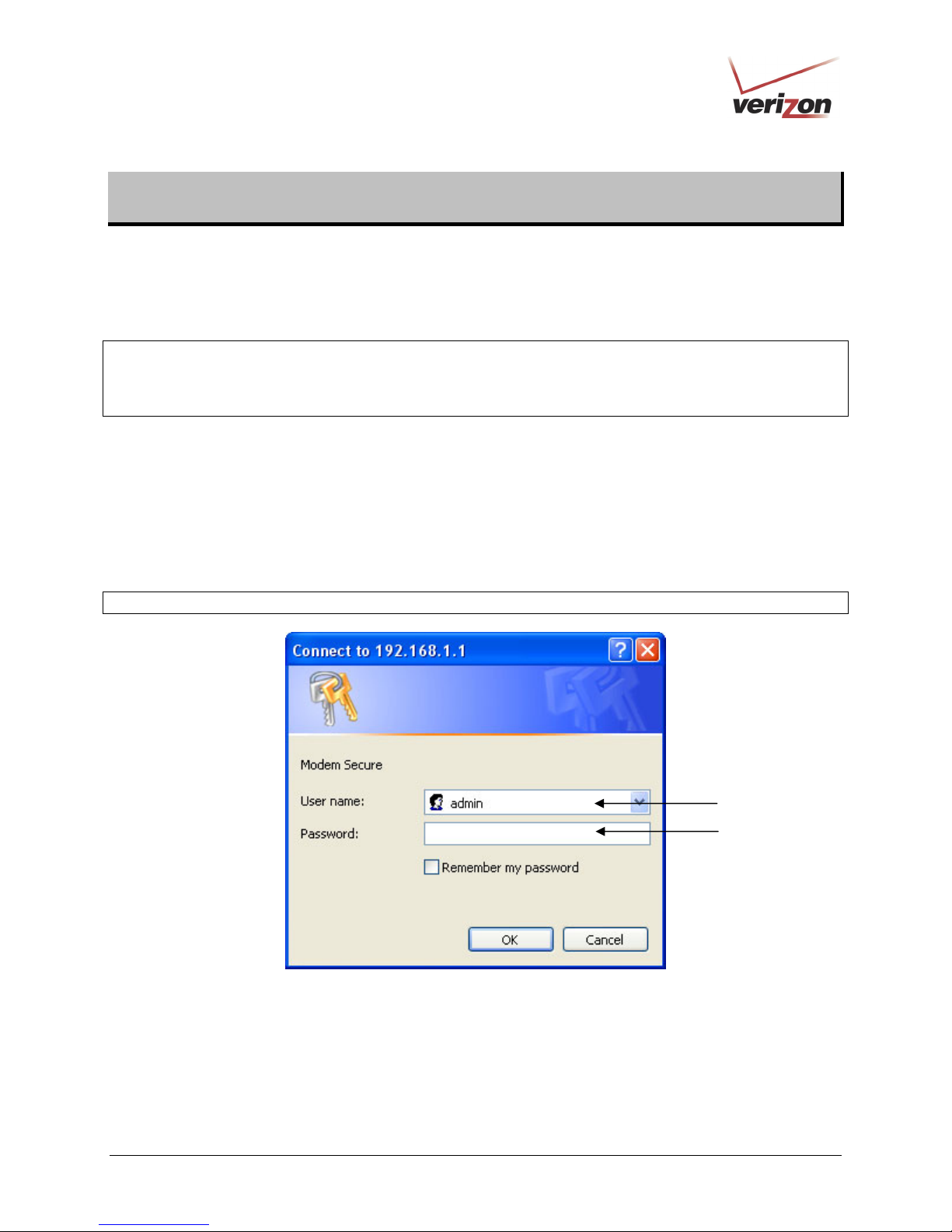
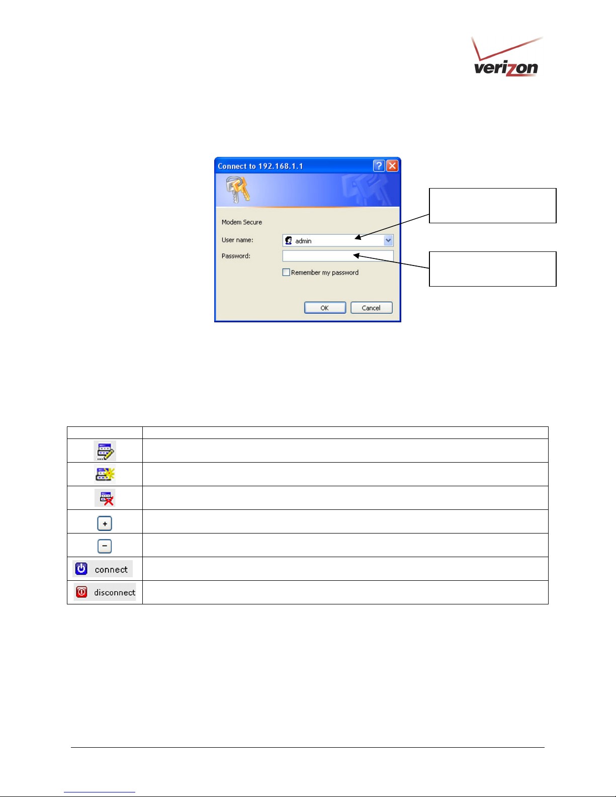
To log on to VersaLink, start your Web browser and type the following IP address in the browser’s address bar:
http://192.168.1.1
After you type the IP address, press Enter on your keyboard. The following Modem Secure screen will appear.
Type the default user name (which is
provided. Click OK.
NOTE: Hereafter, the VersaLink Wireless Gateway will be referred to as the “Router” or “Modem.”
admin) and the default password (which is password) in the fields
030-300505 Rev. A 15 April 2007
admin
asswor
Page 16
)
User GuideVersaLink Wireless Gateway (Model 327W
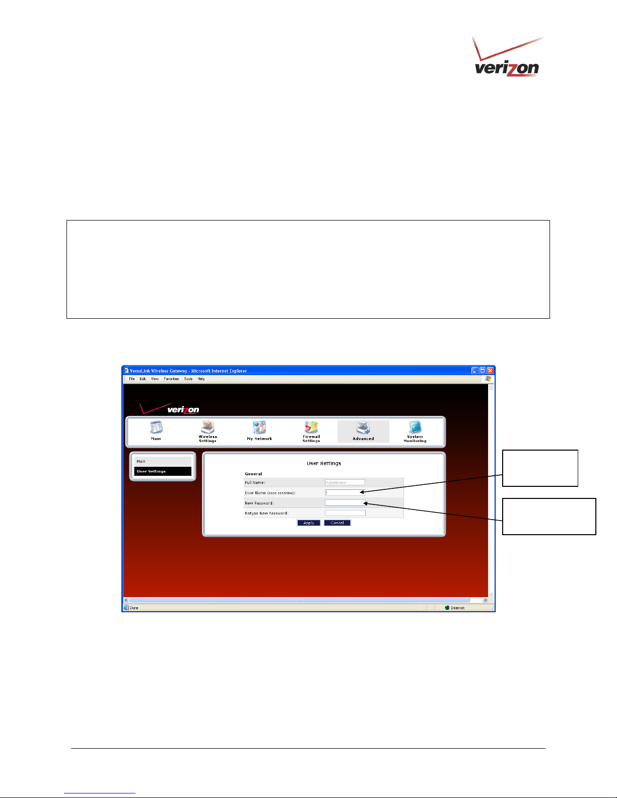
7.2 Changing the Password
After you have clicked OK in the Modem Secure screen, the following User Settings screen will appear. This
screen allows you to change the default administrator name and password to the values of your choice. The
password change is required to continue your network logon. If the Router is password protected and you are not an
authorized user, you will not be able to change the values in this screen. The Router cannot be configured unless an
authorized user is logged in. If necessary, contact your network administrator for further instructions.
IMPORTANT:
1. The User Settings screen allows you to use admin as your administrator name (your administrator name can
match your user name). However, this screen does not allow you to use “password” as your administrator
password. If you enter password in the fields, this screen will not continue the logon. You must enter a different
password in order for this screen to take effect. The values in these fields are case sensitive. Once you decide on
an administrator name and password, please record them for future reference.
2. This feature changes the Administrator’s password, not the PPP password.
Type your administrator User Name and Password in the fields provided. The password fields will be masked for
security purposes.
Type admin or
the name of
your choice.
Type a new password.
(Do not type the word
password here.)
030-300505 Rev. A 16 April 2007
Page 17
)
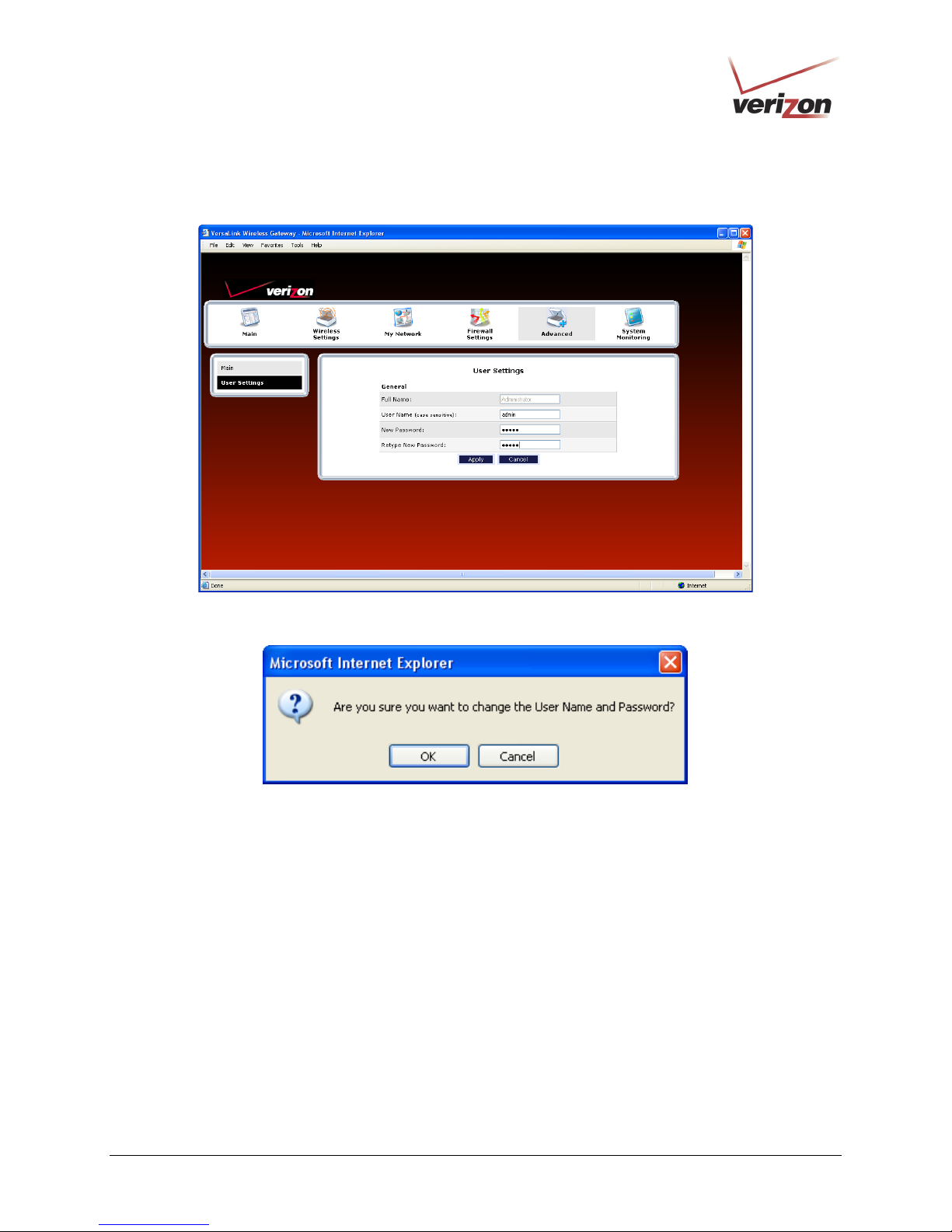
After you have entered the desired values, click Apply.
User GuideVersaLink Wireless Gateway (Model 327W
If you clicked Apply, the following pop-up screen will appear. Click OK to allow the changes to take effect.
030-300505 Rev. A 17 April 2007
Page 18
)
User GuideVersaLink Wireless Gateway (Model 327W
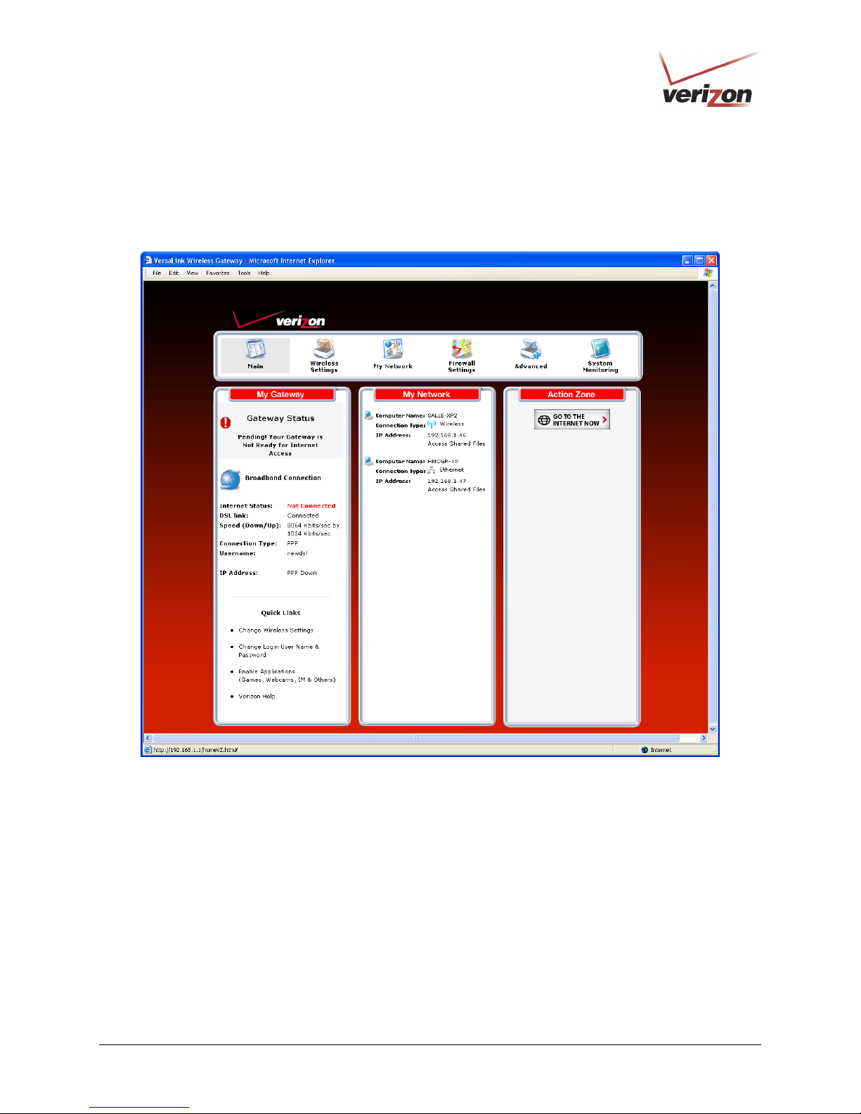
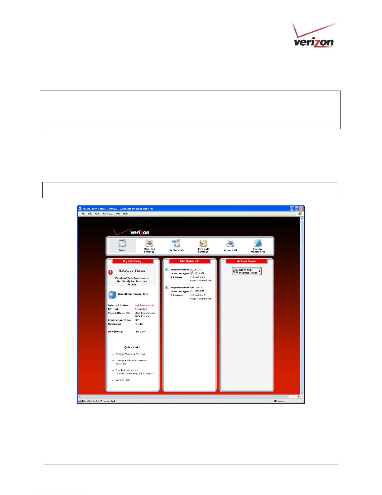
If you clicked OK in the pop-up screen, the following screen will appear. This is the main page of your Router’s Web
pages, also referred to in this document as the home page. You can access this page by clicking Main in the
navigational menu located across the top of the Router’s Web pages. Details on this page will explained in the
following sections.
030-300505 Rev. A 18 April 2007
Page 19
)
User GuideVersaLink Wireless Gateway (Model 327W
8. CONFIGURING YOUR BROADBAND CONNECTION
To browse the Internet using your Router, you must confirm your DSL connection, set up your account profile, and
establish a DHCP or PPP session with your Internet service provider (ISP). The procedures for configuring your
Router’s connection settings are explained in this section.
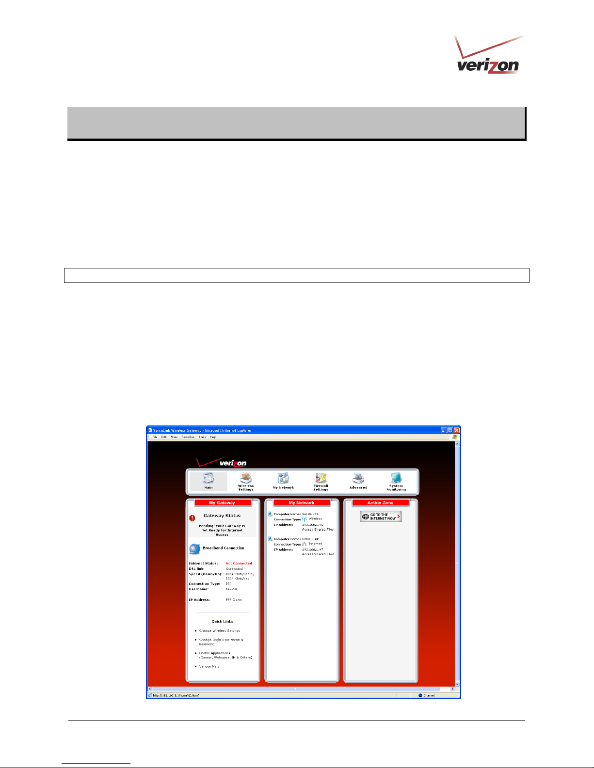
8.1 Confirming Your DSL Connection
After you have logged on to the Router and changed your administrator password, as explained in section 7, the
following home page will appear. Use this page to determine the status of your DSL and Internet connections.
IMPORTANT: You must have active DSL service before the Router can synchronize with Verizon’s equipment.
To determine if the Router has established a DSL link, do any of the following:
• In the My Modem panel of the Main page, view the DSL link field. If the status reads Not Connected,
you do not have a DSL link. However, if DSL Link field displays Connected and the Speed (Down/Up)
field displays numeric values, a DSL link has been established. The values displayed represent the
transmission rates of your DSL signal, downstream and upstream. (You may need to wait a brief moment
for the Router to report these values.)
• At the front of the Router, check to see if the Router’s DSL LED is solid green. Solid green indicates that
the Router’s DSL connection has been established. (The DSL LED may flash while the connection is being
established.) Please wait a brief moment for the Router to connect.
030-300505 Rev. A 19 April 2007
Page 20
)
After confirming your DSL link, DHCP customers can now browse the Internet. However, PPP customers will need
to complete further instructions, as explained in the following note.
NOTE: If the Router has established a DSL link and if you are connecting to the Internet via DHCP, you can now
browse the Internet by following the instructions provided by Verizon. However, if you are connecting to the
Internet via PPP, please proceed to section 8.2 to configure your Router’s broadband connection settings. After you
have configured the broadband settings and connected to the Internet, view the My Modem panel; the Internet
Status field will display Connected.
User GuideVersaLink Wireless Gateway (Model 327W
8.2 Setting Up an Account Profile
Your account profile is used to identify you to Verizon. To begin your account setup, go to the My Modem panel in
the home page. Next, click the Not Connected link.
NOTE: Before you set up your account profile, obtain your Account ID and Account Password from Verizon.
You will use this information when you set up your account parameters.
030-300505 Rev. A 20 April 2007
Page 21
)
User GuideVersaLink Wireless Gateway (Model 327W
If you clicked Not Connected in the preceding screen, the following pop-up screen will prompt you for a user name
and password. Enter the User name and Password that you used in the User Settings screen, in section 7.2, and
then click OK to continue.
Enter the name used in the
User Settings screen.
Enter the password used in
the User Settings screen.
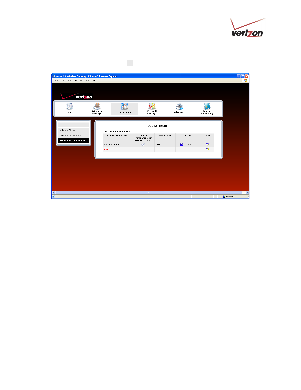
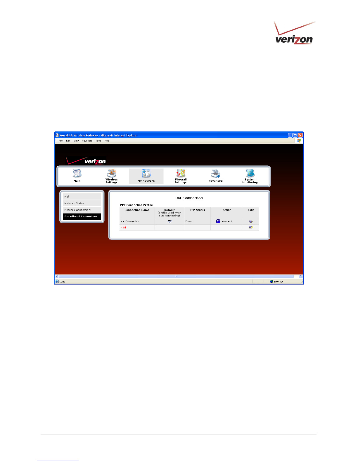
If you clicked OK, the following DSL Connection screen will appear. This screen displays information about your
Internet connection and allows you to access the Router’s connection settings. If you have not set up your account
profile, the PPP Status field will display Down, indicating that you have not established an Internet connection with
Verizon.
Throughout this User Guide, the following icons are used to indicate clicking actions that you can take with your
mouse to configure the Router’s settings.
Icon Description
Details/Edit
Clicking this icon allows you to either view the details of or edit your Router’s settings.
Add/New
Clicking this icon allows you to add new entries your Router.
Delete
Clicking this icon allows you to delete an entry from your Router.
Expand
Clicking this icon allows you to expand the page to view additional entries.
Collapse
Clicking this icon allows you to collapse the page.
Connect
Clicking this icon allows you to connect to Verizon
Disconnect
Clicking this icon allows you to disconnect from Verizon.
030-300505 Rev. A 21 April 2007
Page 22
)
To set up your account profile. Click the Edit
User GuideVersaLink Wireless Gateway (Model 327W
icon.
• Connection Name: The name of the connection profile your are using for your Internet connection.
• Default: The name of the default profile that is used when the Router auto connects to the ISP.
• PPP Status: The status of the PPP connection. Down = no PPP connection, Up = PPP connection is
established.
• Action: Click the icon in the Action column to connect to Verizon or to disconnect from Verizon (end your
PPP session). If you end your PPP session, this does not end your DSL connection.
• Add: Click the Add link to add additional profiles to your Router.
• Edit: Click the Edit icon for My Connection to set up your connection profile. My Connection is the name of
the default connection profile that you will use to connect to Verizon. Then, if you want, you can click Add to
add additional connection profiles, and assign one as your default profile.
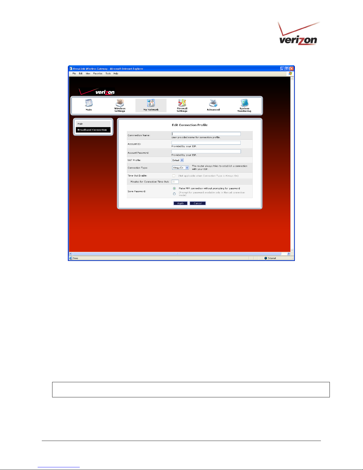
If you clicked Edit in the preceding screen, the following Edit Connection Profile screen will appear. Type your
account parameters in the fields provided. The following account parameters are required for your Internet
connection:
• Connection Name: The Connection Name is a word or phrase that you use to identify your account.
• Account ID: The Account ID is provided by Verizon
• Account Password: The Account Password is provided by Verizon.
030-300505 Rev. A 22 April 2007
Page 23
)
User GuideVersaLink Wireless Gateway (Model 327W
Next, select the connection type (Manual, On Demand, Always On) that you want to use for your default connection
profile.
• Manual: Select this option if you want to manually establish your PPP session.
• On Demand: Select this option if you want the Router to automatically reestablish your PPP session on
demand anytime your PC requests Internet activity (for example, browsing the Internet, email, etc.). Please note
that when you have Internet traffic, this setting may cause a delay.
• Always On: Select this option if you want the Router to automatically establish a PPP session when you log on
or if the PPP session goes down. The Router’s factory default setting is Always On.
If you enable the Router’s timeout feature, the Router will end the PPP session upon reaching the number of minutes
you specify for connection timeout. To configure connection timeout, do the following:
1. In the Connection Type field, select either Manual or On Demand as the connection setting.
NOTE: The Time Out Enable feature does not apply to Always On, only to On Demand and Manual, and the
timeout option will be dimmed if you select Always On. The Router’s default connection type is Always On.
2. Next, click the Time Out Enable check box (a check mark will appear in the box).
3. Type the number of minutes in the Minutes for Connection Time Out box.
030-300505 Rev. A 23 April 2007
Page 24
)
User GuideVersaLink Wireless Gateway (Model 327W
To save your account password, in the Save Password field, click the top option button. Clicking this option button
allows the Router to make a PPP connection without first prompting you for a password. (By default this option is
already selected; the Router will automatically save the account password.) If you want the Router to prompt you for
the account password, select Manual as the connection type, and then click the bottom option button in the Save
Password field. (The Router will prompt you for a password only if you have selected Manual as the connection
type.)
After you have entered the appropriate settings in the Edit Connection Profile screen, click Apply to allow the
settings to take effect. The following DSL Connection screen will appear.
030-300505 Rev. A 24 April 2007
Page 25
)
User GuideVersaLink Wireless Gateway (Model 327W
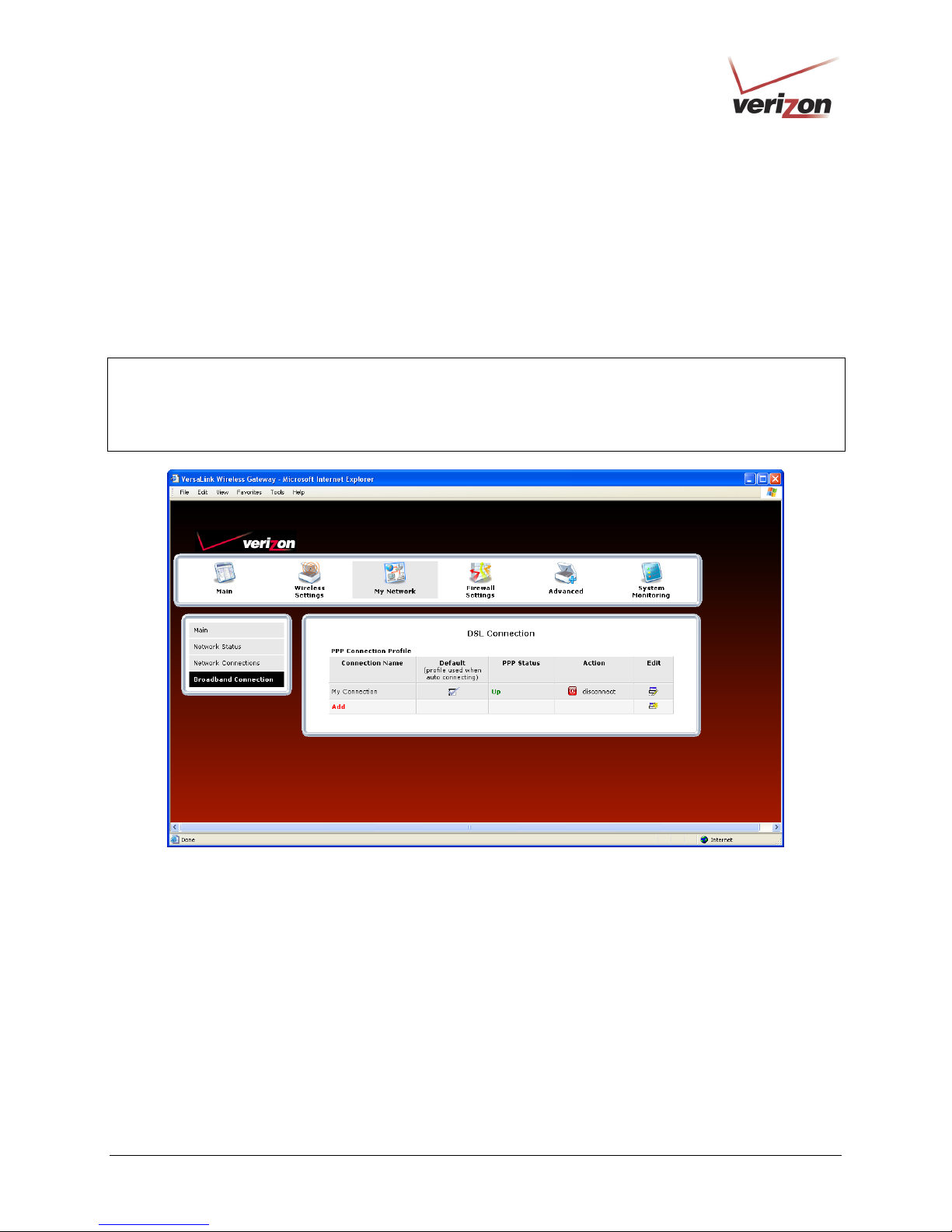
8.3 Connecting to the Internet
After you have set up your account profile using the steps explained in section 8.2, you are ready to establish a PPP
session (Internet connection) with Verizon. View the DSL Connection screen. If the PPP Status field displays
Down, you do not have an Internet connection established. To establish an Internet connection, click connect. The
PPP Status field will briefly display connecting; this means that the Router is establishing a PPP session. After
Router’s establishes a PPP session, the PPP Status field will display Up. Congratulations! You can now browse the
Internet.
NOTE: Whenever the PPP Status displays Down, you do not have a PPP session established. If your Router’s
connection setting is set to Always On or On Demand, after a brief delay the PPP session will be established
automatically, and PPP Status will display Up. However, if the connection setting is set to Manual, you must click
the connect button to establish a PPP session. Once the PPP session has been established (PPP Status displays Up),
you can browse the Internet.
030-300505 Rev. A 25 April 2007
Page 26
)
User GuideVersaLink Wireless Gateway (Model 327W
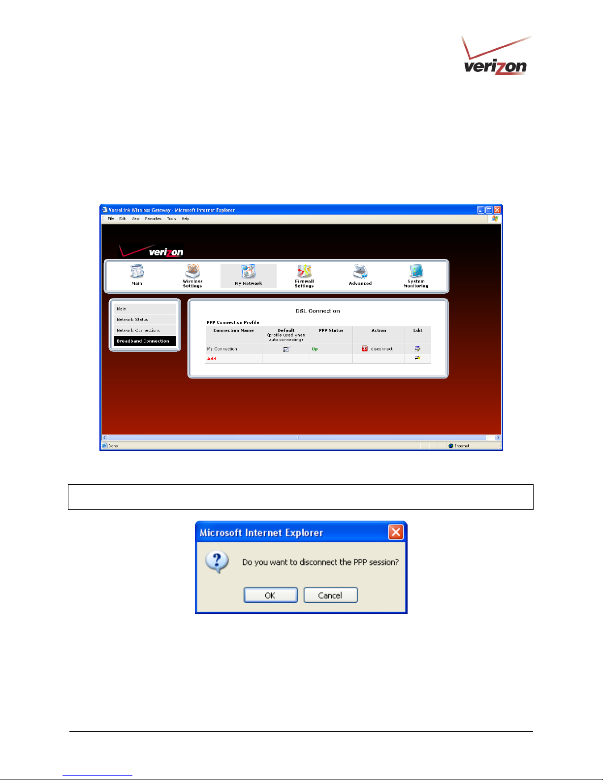
8.4 Disconnecting from the Internet
If you have finished browsing the Internet and want to disconnect from your Internet service provider, from the My
Modem panel in the home page, click the connected link (next to Internet Status). The following DSL Connection
screen will appear. Click disconnect to end your PPP session.
If you clicked disconnect, the following pop-up screen will appear. Click OK to continue.
IMPORTANT: If you disconnect the PPP session, this will disconnect the Router from the Internet, and Internet
access for any device connected to your LAN will be unavailable until the PPP session is reestablished.
030-300505 Rev. A 26 April 2007
Page 27

)
User GuideVersaLink Wireless Gateway (Model 327W
If you clicked OK to disconnect your PPP session, after a brief moment, the PPP Status in the DSL Connection
screen should display Down.
Also, at the home page in the My Modem panel, the Internet Status field will display Not Connected. Although
your Internet connection is down, your DSL session will not be affected. When you are ready to end your DSL
session, simply turn off the Router via the power switch on the Router’s rear panel.
NOTE: When you are ready to exit the Router’s interface, click the X (close) in the upper-right corner of the
window. Closing the window will not affect your PPP Status (your PPP session will not be disconnected) or your
DSL connection. You must click the disconnect button to disconnect your PPP session. When you are ready to
restore the Router’s interface, start your Internet browser and then type http://192.168.1.1 in the browser’s address
bar. Next, press Enter on your keyboard.
030-300505 Rev. A 27 April 2007
Page 28
)
User GuideVersaLink Wireless Gateway (Model 327W
9. SETTING UP MACINTOSH OS X
This section provides instructions on how to use Macintosh Operating System 10 with the Router. Follow the
instructions in this section to create a new network configuration for Macintosh OS X.
NOTE: Macintosh computers must use the Router’s Ethernet installation. Refer to section 6, “Installing the
Hardware,” for details.
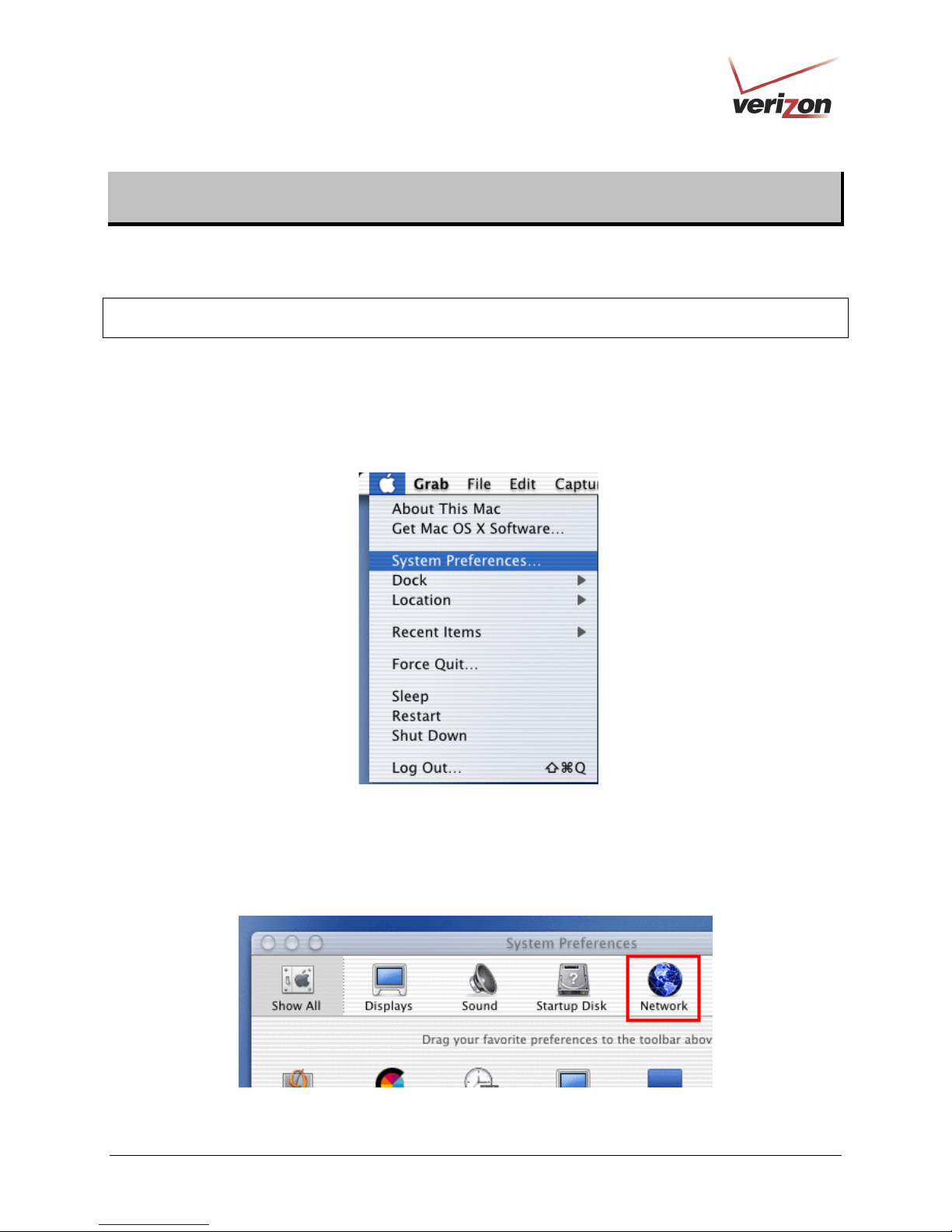
9.1 Opening the System Preference Screen
After you have connected the Router to the Ethernet port of your Macintosh, the screen below will appear. Click the
“Apple” icon in the upper-left corner of the screen and select System Preferences.
9.2 Choosing the Network Preferences
After selecting System Preferences from the previous screen, the following screen will appear. Click the Network
icon.
030-300505 Rev. A 28 April 2007
Page 29
)
User GuideVersaLink Wireless Gateway (Model 327W
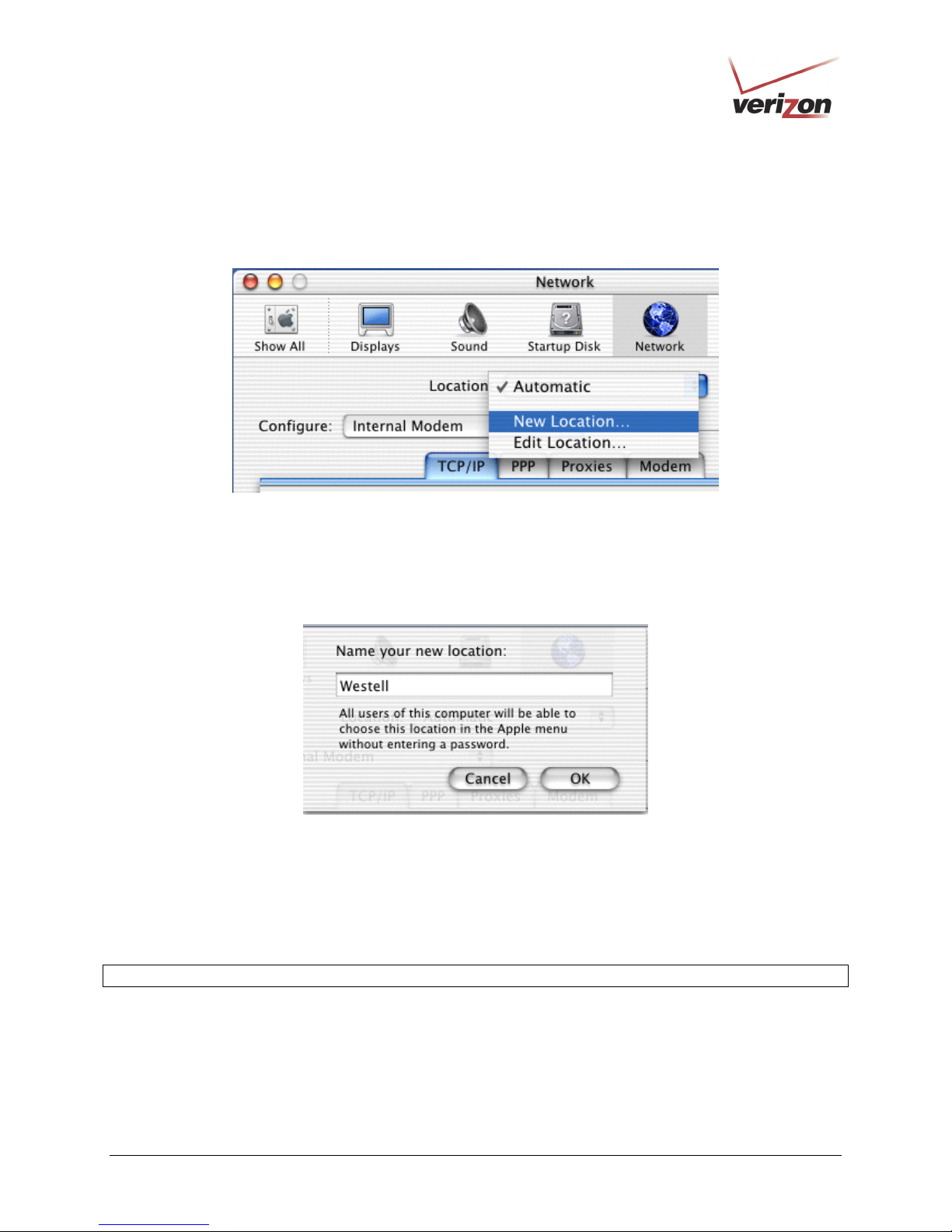
9.3 Creating a New Location
After clicking the Network icon, the Network screen will appear. Select New Location from the Location field.
9.4 Naming the New Location
After selecting New Location in the Network screen, the following screen will appear. In the field labeled
Name your new location:, change the text from “Untitled” to “Westell.” Click OK.
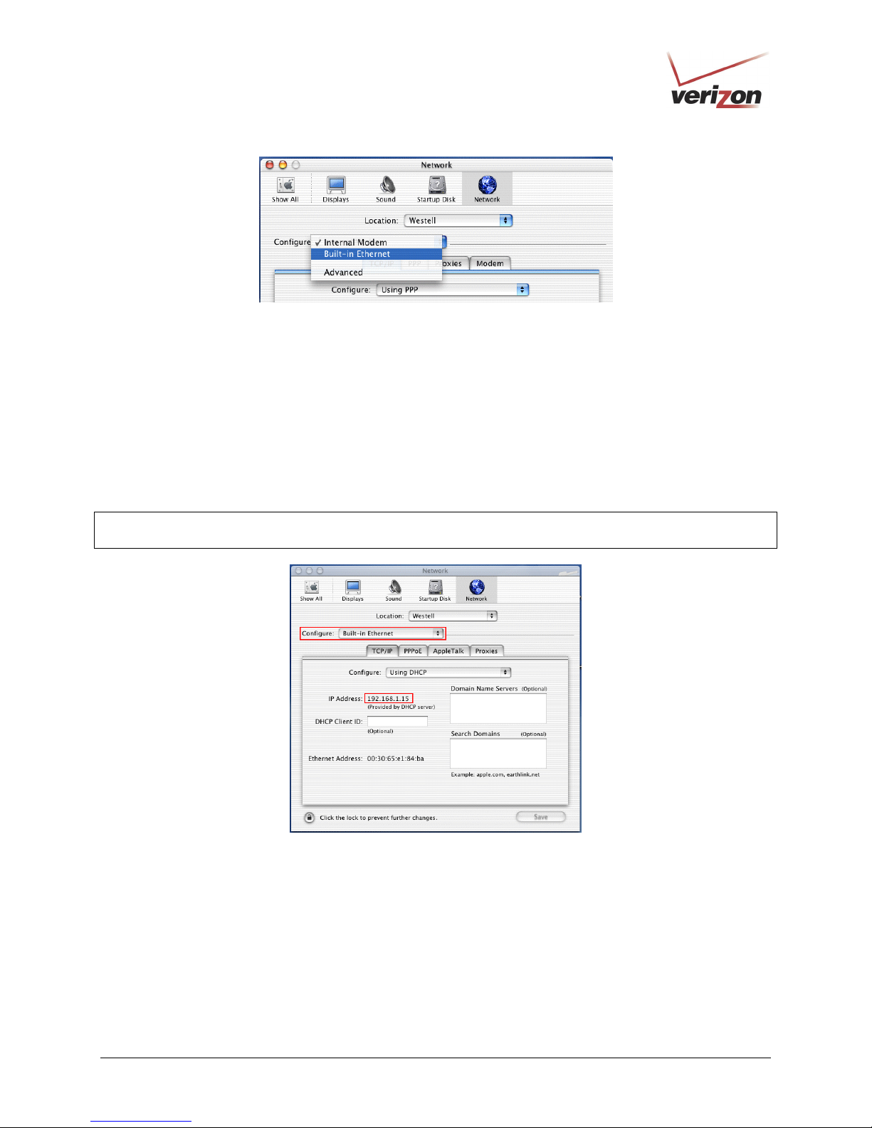
9.5 Selecting the Ethernet Configuration
After clicking OK in the preceding screen, the Network screen will appear. The Network screen shows the settings
for the newly created location. From the Configure field in the Network screen, select Built-in Ethernet. Click
Save to save the settings.
NOTE: Default settings for the Built-in Ethernet configuration are sufficient to operate the Router.
030-300505 Rev. A 29 April 2007
Page 30
)
User GuideVersaLink Wireless Gateway (Model 327W
9.6 Checking the IP Connection
To verify that the computer is communicating with the Router, follow the instructions below.
1. Go to the “Apple” icon in the upper-left corner of the screen and select System Preferences.
2. In the System Preferences screen, click the Network icon. The Network screen will appear.
3. In the Configure field in the Network screen, select Built-in Ethernet.
4. View the IP address field. An IP address that begins with 192.168.1 should appear.
NOTE: The Router’s DHCP server provides this IP address. If this IP address is not displayed, check the Router’s
wiring connection to the PC. If necessary, refer to section 6, “Installing the Hardware,” for installation instructions.
030-300505 Rev. A 30 April 2007
Page 31

)
User GuideVersaLink Wireless Gateway (Model 327W
9.7 Accessing Your Router
In your Internet Explorer Web browser address bar, type http://dslrouter/. Next, press Enter on your keyboard.
The Modem Secure screen will appear. Please proceed to the Modem Secure screen in section 7.1 of this User
Guide for logon instructions.
030-300505 Rev. A 31 April 2007
Page 32

)
User GuideVersaLink Wireless Gateway (Model 327W
10. BASIC CONFIGURATION
IMPORTANT: The following sections assume that you have active DSL and Internet service.
VersaLink allows you to make changes to the configurable features of your Router such as account profiles, routing
configurations, and firewall settings. The following sections explain each feature and show you how to make
changes to the Router’s settings. The navigational menu displayed at the top of each page allows you to navigate to
the various configuration screens of your Router. Whenever you change the configurable settings of your Router,
you must click Apply (or Save where applicable) to allow the changes to take effect in the Router.
NOTE: If you need help, go to the Quick Links section in the home page and then click Verizon Help. Clicking
this link takes you to Verizon’s OnLine Help site where you can find additional information about your DSL Router.
To configure the basic settings in your Router, follow the instructions provided in sections 11 through 14.
NOTE: The menu options displayed will vary according to the configuration you have chosen to use, LAN
Ethernet port or WAN Uplink port. If you are using WAN Uplink port, some menu options will not be available.
However, all menu options will be available when the Router is configured for LAN Ethernet port. Instructions on
enabling and disabling LAN Ethernet port and WAN Uplink port are explained in the section 13.2.3, “Configuring
VersaPort.” This document was created with the Router configured for LAN Ethernet port mode.
030-300505 Rev. A 32 April 2007
Page 33

)
User GuideVersaLink Wireless Gateway (Model 327W
11. MAIN (HOME PAGE)
After you have logged on to your Router and established a PPP session with your Internet service provider (ISP), click
Main in the top navigational menu. The following home page will appear. The home page allows you to view
connection information reported by your Router and to quickly access Internet services provided by Verizon. The
following sections discuss each panel in the Main page. The Main page will be referred to as the home page
throughout this User Guide.
030-300505 Rev. A 33 April 2007
Page 34

)
User GuideVersaLink Wireless Gateway (Model 327W
11.1 My Gateway Panel
In the home page, the My Modem panel allows you to view details about your Router’s connections and to access
the connection settings in your Router. A green check mark displayed in the Modem Status check box signals you
to Go! You can now browse the Internet. The Quick Links section allows you to quickly access Help information
related to your Router and information on your Router’s configurable settings. The following details are displayed in
the My Modem panel.
My Modem
Internet Status This field displays status of your Internet connection. Click this link to set up new
account profiles, edit existing account profiles, and connect to or disconnect from
Verizon. Additional details about your Router’s broadband connection can be found
in section 8.2, “Setting Up an Account Profile,” of this User Guide.
DSL Link This field allows you to view the status of your DSL connection.
Speed (Down/Up) This field displays the transmission rates (in Kbits/sec) of your DSL signal. Down is
the rate at which data is transmitted downstream (from the Internet to your computer).
Up is the rate at which data is transmitted upstream (from your computer to the
Internet).
Connection Type This field displays the protocol used for your Internet connection, provided by
Verizon.
Username This field displays the username that you used to connect to Verizon. The username
and password are provided by Verizon.
Internet IP Address This is a WAN IP address that has been assigned to your Router by Verizon. You will
receive the WAN IP address only after your Router has established an Internet
connection with Verizon. (The LAN IP address of your Router is “192.168.1.1”
which is assigned to your Router by factory default.)
Change Wireless Settings Click this link to change the Router’s wireless settings.
Change Login User Name
& Password
Enable Applications
(games, webcams, IM, etc.)
Verizon Help Click this link to access Verizon’s Online Help where you can obtain detailed
Click this link to change the administrator user name and password.
Click this link to set up a service profile and attach VPN, Gaming, or other NAT
services to the profile.
information about your Router.
11.2 My Network Panel
In the home page, the My Network panel allows you to view information about devices that are connected to your
network. If your network provides access to shared files, you can access the files by clicking the Access Shared
Files link. The following details are displayed in the My Network panel.
My Network
Computer Name The ASCII (text) name of the device connected network
Connection Type The physical connection used to interface with your Router.
IP Address The IP address assigned to your computer by your Router’s DHCP server.
Access Shared Files Click this link to access shared files from a device on your local network. (The device
must have file sharing enabled.) Note: If the device has a firewall turned on, you will
not be able to access shared file from the device.
030-300505 Rev. A 34 April 2007
Page 35

)
User GuideVersaLink Wireless Gateway (Model 327W
11.3 Action Zone Panel
In the home page, the Action Zone panel allows quick access to Internet services provided by Verizon. The
following details are displayed in the Action Zone panel.
NOTE: The links displayed in the Action Zone panel are specific to the services offered by Verizon and will be
available only after you have established a PPP session (Internet connection) with Verizon.
Action Zone
Click this button to go to the default page of your Web browser. (Clicking this button
will take you to the browser’s default page. However, if your PPP session is down, you
Go to the Internet Now
Verizon Click the links in this section to access networking services provides by Verizon.
Shop Westell Click this button to go to Westell’s home page.
Music Click this button to go to the Verizon Surround - Music page.
Video Click this button to go to the Verizon Surround - Movies page.
do not have Internet access. To browse the Internet, you must first establish a PPP
session with Verizon.) When you are ready to return to the Router’s Web interface,
type http://192.168.1.1/ in your Internet browser’s address bar, and press Enter on
your keyboard.
030-300505 Rev. A 35 April 2007
Page 36

)
User GuideVersaLink Wireless Gateway (Model 327W
12. WIRELESS SETTINGS
If you click Wireless Settings in the top navigational menu, the following screen will appear. This screen allows
you to you configure the Router’s wireless connection settings.
030-300505 Rev. A 36 April 2007
Page 37

)
User GuideVersaLink Wireless Gateway (Model 327W
12.1 Basic Security Settings
If you select Wireless Settings from the top navigation menu and then select Basic Security Settings in the submenu
options at the left of the screen, the following screen will appear. Enter the appropriate settings in the fields provided,
and then click Apply to allow the settings to take effect. The following table explains the details of this feature.
IMPORTANT:
1. If you are connecting to VersaLink via a wireless network adapter, the computer’s wireless network adapter must
be configured with VersaLink’s Service Set ID (SSID) in order to communicate with VersaLink; that is, the SSID
used in the wireless network adapter must be identical to VersaLink’s SSID. The default SSID for VersaLink is
the serial number of the unit (located below the bar code on the bottom of the unit and also on the shipping
carton). Locate and run the utility software provided with the wireless network adapter, and then enter the
identical SSID and security settings displayed in the VersaLink. For privacy, you can change the SSID and
security settings to your desired values.
2. In order for every computer on your network to connect to your VersaLink wirelessly, confirm that each computer
is using the same security settings that you have configured in VersaLink’s Basic Security Settings screen. After
you have configured all the settings in this screen, please record the settings for future reference.
030-300505 Rev. A 37 April 2007
Page 38

)
User GuideVersaLink Wireless Gateway (Model 327W
Wireless Operation Factory Default = On
Choose the desired setting.
When On is selected, wireless stations (wireless computers or other wireless devices) can
connect to the Router, as long as the appropriate settings are configured in the wireless
station’s network adapter.
When Off is selected, computers will not be able to connect to the Router wirelessly.
Network Name (SSID) Factory Default = 06B410749516
This string, (30 characters or less) is the name of your wireless network. To connect to the
Router, the SSID on a computer’s wireless card must match the SSID on the Router. You
can change the SSID to any name or code you want.
Channel Factory Default = 6
This is the channel of the frequency band at which the Router communicates.
The Router transmits and receives data on this channel. The number of channels to choose
from is pre-programmed into the Router. A computer’s wireless card does not have to be
set to the same channel as the Router; the wireless cards scan all channels, and look for a
Router to connect to. Note: In the United States, use channels 1 through 11.
WEP configured Factory Default = On
030-300505 Rev. A 38 April 2007
Basic Security Settings
Page 39

)
User GuideVersaLink Wireless Gateway (Model 327W
Click the desired option button.
If WEP is selected, the Router will allow you to enter WEP key values for wireless
security, and any wireless computer can connect to the Router (as long as its SSID and
security settings matches the Router’s).
If Off is selected, you will not be allowed to enter WEP key values, and wireless traffic
will not be encrypted. This maximizes the risk of unauthorized access to your computer.
WEP Key Entry Type Factory Default = Hex
Choose the desired WEP Key EntryType from the drop-down menu.
A WEP key is treated as either a string of text (ASCII) characters or a set of hexadecimal
(Hex) characters.
Possible Responses:
Hex (hexadecimal) – Selecting Hex allows you to enter characters from (A-F) or (0-9) as
the key code.
ASCII (text) – Selecting ASCII allows you to enter characters from (A-Z) or (0-9) as the
key code.
WEP Key Choose the desired WEP Key encryption from the drop-down menu.
The WEP key value is used to encrypt your wireless traffic.
The Router supports 64/40-bit, 128/104-bit, or 256/232-bit WEP encryption.
Key Code
Enter the key code values in this field.
ASCII: If you are using an ASCII key code, the number of characters entered into this
field must be either 5 (for 40/64 bit encryption), 13 (for 128 bit encryption) or 29 (for
256 bit encryption).
HEX: If you are using a Hex key code, the number of characters that you can enter into
this field must be either 10 (for 40/64 bit encryption), 26 (for 128 bit encryption) or 58
(for 256 bit encryption). The only allowable hexadecimal characters are: A-F and 0-9.
Note: Do not use symbols or blank spaces in the key code field.
4x Support Factory Default = Off
Select On to turn on the 4X feature.
Select Off to turn off the 4X feature.
When On is selected, this feature provides additional algorithms for increased wireless
throughput. Note: This feature will only operate with wireless clients that support this
feature. Verify with the manufacturer of your wireless client that 4X is supported.
Current Wireless Status Displays the settings and packet information for your Wireless connection. Settings
displayed in this window can be configured through the Basic Security Settings screen or
through the Advanced Security Settings screen.
030-300505 Rev. A 39 April 2007
Page 40

)
User GuideVersaLink Wireless Gateway (Model 327W
12.2 Advanced Security Settings
If you select Wireless Settings from the top navigational menu and then select Advanced Security Settings in the
submenu options at the left of the screen, the following screen will appear. The following table explains the details of
the Advanced Security Settings screen.
IMPORTANT: Only the advanced user should change the settings in this screen. If you need to reset the Router to
factory default settings, press the reset button at the rear of the Router. Or follow the instructions in section 15.2,
“Restore Defaults,” to restore the Router to factory default settings.
Advanced Security Settings
Wireless Security Factory Default = WEP (recommended)
WEP – Selecting WEP allows you to enable a WEP key for wireless security. The Router’s card
supports 64-bit, 128-bit, or 256-bit WEP encryption. If WEP is selected, any station can connect to the
Router (as long as its SSID matches the Router’s SSID).
WPA – Selecting WPA allows you to enable a pre-shared key for home network or more advanced
security for an enterprise network.
SSID Broadcast Allows you to prevent unauthorized wireless access to your Router by blocking the Router’s SSID on
the network.
When SSID Broadcast is enabled, any computer or wireless device using the SSID of “ANY” can see
the Router. To prevent this from happening, disable SSID broadcast so that only the wireless devices
that know your SSID can access your Router.
Wireless MAC
Authentication
802.11b/g Mode Allows you to limit access to your Router based on technology type.
030-300505 Rev. A 40 April 2007
Allows you to limit access to your wireless network by allowing only devices with specific MAC
address to connect to your Router.
11b only: Communication with VersaLink is limited to 802.11b
11g only: Communication with VersaLink is limited to 802.11g
Mixed Mode: Computers using any of the 802.11b or 802.11g rates can communicate with VersaLink.
Page 41

)
User GuideVersaLink Wireless Gateway (Model 327W
12.2.1 Securing the Wireless Traffic
In the Advanced Security Settings screen, select one of the following options to secure your wireless traffic.
• WEP: Selecting this option button allows you to enable a WEP key for wireless security. (WEP is the
recommended setting.)
• WPA: Selecting this option button allows you to enable a pre-shared key for a home network or for more
advanced security for an enterprise network.
030-300505 Rev. A 41 April 2007
Page 42

)
User GuideVersaLink Wireless Gateway (Model 327W
12.2.1.1 WEP Security
If you select WEP in the Advanced Security Settings screen, the following screen will be displayed.
NOTE: A WEP key is treated as either a string of text (ASCII) characters or a set of hexadecimal (Hex)
characters. The number of text characters must be either 5 (for 40/64 bit encryption), 13 (for 128 bit encryption)
or 29 (for 256 bit encryption). The number of Hex characters must be either 10 (for 40/64 bit encryption), 26 (for
128 bit encryption) or 58 (for 256 bit encryption). The only allowable hexadecimal characters are: A-F and 0-9.
030-300505 Rev. A 42 April 2007
Page 43

)
User GuideVersaLink Wireless Gateway (Model 327W
12.2.1.2 WPA Security
If you select WPA in the Advanced Security Settings screen, the following screen will appear. Enter the
appropriate values in the fields, and then click Apply to allow the settings to take effect.
NOTE: A WPA key is treated as either a string of text (ASCII) characters or a set of hexadecimal (Hex)
characters. The WPA key can be either 8 to 63 text (ASCII) characters or 64 hexadecimal (Hex)
characters. The only allowable hexadecimal characters are: 0-9, and A-F.
WPA
Authentication Method Factory Default = Personal (Pre-Shared Key)
Personal (Pre-Shared Key) – WPA stations share a pre-shared key (string format) with the
Router and do not authenticate with the RADIUS server.
Enterprise 802.1x – WPA stations authenticate with the RADIUS server using EAP-TLS over
802.1x, a standard for passing extensible authentication protocol (EAP) for authentication
purposes. EAP is used to communicate authentication information between the supplicant and
the authentication server. With 802.1x EAP messages are packaged in Ethernet frames, rather
than using and PPP.
WPA Type Factory Default = WPA Any
WPA Any – Allows stations that support WPA, WPA2, or WPA Any to connect to the Router.
WPA – Allows stations that support WPA v.1 to connect to the Router.
WPA2 – Allows stations that support WPA v.2 to connect to the Router.
WPA2 PreAuthentication
Factory Default = Disabled
To Enable this feature, click the box (a check mark will appear in the box).
WPA Shared Key The WPA key can be either 8 to 63 text (ASCII) characters or 64 hexadecimal (Hex) characters.
The only allowable hexadecimal characters are: A-F and 0-9.
Group Key Update
Interval (in seconds)
The number of seconds between rekeying the wPA group key. A value of zero means that
rekeying is disabled.
030-300505 Rev. A 43 April 2007
Page 44

)
User GuideVersaLink Wireless Gateway (Model 327W
After you have entered your values and clicked Apply in the WPA screen, the following pop-up screen will appear.
The pop-up screen indicates that wireless access may be interrupted. Click OK to continue.
NOTE: Wireless access to the Router may be interrupted and wireless stations may require reconfiguration.
030-300505 Rev. A 44 April 2007
Page 45

)
User GuideVersaLink Wireless Gateway (Model 327W
12.2.2 SSID Broadcast
If you click the SSID Broadcast link in the Advanced Security Settings screen, the following screen will be
displayed. When SSID Broadcast is enabled, any computer or wireless device using the SSID of “ANY” can see the
Router. To prevent this from happening, click the Disable option button. This will disable SSID Broadcast so that
only the wireless devices that are configured with your SSID can access your Router.
Click the desired option button, and then click Apply to allow the settings to take effect. Click Back to return to the
Advanced Security Settings screen.
030-300505 Rev. A 45 April 2007
Page 46

)
User GuideVersaLink Wireless Gateway (Model 327W
12.2.3 Wireless MAC Authentication
If you select the Wireless MAC authentication link in the Advanced Security Settings screen, the following
screen will appear. This screen allows you configure wireless MAC address authentication in the Router. By
enabling the Access List, you can permit or restrict wireless access to the Router based on specific MAC addresses.
To limit access to the Router using the MAC address of specific wireless devices, follow the steps below:
1. Click the Enable Access List check box (a check mark will appear in the box).
2. Click Apply to save the setting, and then click OK in the pop-up screen.
To add, edit, or delete MAC addresses of wireless devices, click the desired button below the List window.
For example, to Add a MAC address, click Add.
030-300505 Rev. A 46 April 2007
Page 47

)
If you clicked Add, the following screen will appear. Enter the desired settings, and then click Apply.
User GuideVersaLink Wireless Gateway (Model 327W
Traffic Allowed: When the MAC Filter is enabled, only stations in the MAC Filter Table (which are set
to “Allowed”) will have access to the Router.
Blocked: This allows a computer to remain in the table, but it is not allowed access to the Router.
MAC Address The MAC address assigned to the computer that you want to allow access to. (A hardware
address is assigned to a computer or device by the manufacturer.)
Station Name The computer name or description that you want to associate with the MAC address. This is an
optional field that is useful in identifying the station.
The following screen provides an example of values entered into the fields.
030-300505 Rev. A 47 April 2007
Page 48

)
User GuideVersaLink Wireless Gateway (Model 327W
After you have entered your values and clicked Apply in the preceding screen, the following pop-up screen will
appear. The pop-up screen indicates that wireless access may be interrupted. Click OK to continue.
NOTE: Wireless access to the Router may be interrupted and wireless stations may require reconfiguration.
If you clicked OK in the pop-up screen, the following screen will appear. The MAC address has been added to the
list of MAC addresses. Confirm that a ckeck mark is displayed Enable Access List check box, and then click
Apply. Repeat this process for each wireless device that you want to add to the list.
030-300505 Rev. A 48 April 2007
Page 49

)
User GuideVersaLink Wireless Gateway (Model 327W
12.2.4 802.11b/g Mode
If you select the 802.11b/g Mode link in the Advanced Security Settings screen, the following screen will be
displayed. This screen allows you to limit access to your Router based on technology type. From the drop-down
menu, select the desired setting. Then, click Apply to allow the settings to take effect.
11b only: Communication with VersaLink is limited to 802.11b
802.11b/g Mode
030-300505 Rev. A 49 April 2007
11g only: Communication with VersaLink is limited to 802.11g
Mixed mode: Computers using 802.11b or 802.11g technology can communicate with VersaLink.
Page 50

)
User GuideVersaLink Wireless Gateway (Model 327W
12.2.5 Other Advanced Wireless Options
If you select the Other Advanced Wireless Options link in the Advanced Security Settings screen, the following
screen will appear. From the drop-down menus, select the desired settings. Then, click Apply to allow the settings to
take effect.
Beacon Interval The time interval between beacon frame transmissions. Beacons contain rate and
capability information. Beacons received by stations can be used to identify the
access points in the area.
Fragmentation Threshold Any MSDU or MPDU larger than this value will be fragmented into an MPDU of
the specified size.
RTS Threshold RTS/CTS handshaking will be performed for any data or management MPDU
containing a number of bytes greater than the threshold. If this value is larger than
the MSDU size (typically set by the fragmentation threshold), no handshaking will
be performed. A value of zero will enable handshaking for all MPDUs.
Preamble Algorithm Factory Default = Always Long
Possible Responses:
Always Long: Transmissions are done using the long preamble algorithm.
Always Short: Transmissions are done using the short preamble algorithm.
Local STA’s: If all associated stations support short preamble, then the short
preamble algorithm is used. Otherwise, the long preamble algorithm is used.
030-300505 Rev. A 50 April 2007
Wireless Advanced Configuration
Page 51

)
Slot Time Algorithm Factory Default = Local STA’s
Possible Responses:
Always Off: Transmissions are done using a 20 usec slot time.
Always ON: Transmissions are done using a usec slot time (SST).
Local STA’s: If all associated stations support SST, then the 9 usec slot time is
used. Otherwise, the 20 uses slot time is used.
Enhanced Dynamic: Similar to Local STA’s, with the following extension: If
associated stations that do not support SST do not transmit for a period of time, the
9 usec slot time is used.
ERP Protection Algorithm Factory Default = Dynamic
Possible Responses:
Always Off: ERP is not used
Always ON: ERP is used.
Local STA’s: If there are any associated stations than do not support ERP, a
protection algorithm is used to prevent contention.
Dynamic: Similar to local STA’s with the following extension: The ERP protection
setting is also dependent on Beacon frames from overlapping BSS. IF Beacon
frames are received that indicate ERP is not supported, then a protection algorithm
is used.
Enhanced Dynamic: Similar to Dynamic with the following extension: If associated
stations that do not support ERP do not transmit for a period of time, then
protection algorithm is not used.
802.11b Rates (Mbps)
802.11g Rates (Mbps)
These are the allowable communication rates that VersaLink will attempt to use.
The rates are also broadcast within the connection protocol as the rates supported
by VersaLink.
User GuideVersaLink Wireless Gateway (Model 327W
030-300505 Rev. A 51 April 2007
Page 52

)
User GuideVersaLink Wireless Gateway (Model 327W
13. MY NETWORK
This section discusses details about your Router’s network.
13.1 Network Status
To view your Router’s network settings, from the top navigational menu, select My Network. Next, click Network
Status in the submenu at the left of the screen. The following screen will appear. This screen displays information
about the devices connected to your local area network (LAN).
Connection Type The physical connection used to interface with your Router.
IP Address The IP address assigned to your computer.
IP Address Allocation The method by which your computer receives its IP address.
MAC Address
Connected Devices The interfaces used to connect to your Router to the computer.
030-300505 Rev. A 52 April 2007
The Media Access Controller; the hardware address assigned to the deviced by the
manufacturer.
Ethernet: Displays the number of devices that are connected to the Router via Ethernet
10/100 BaseT connection.
Wireless: Displays the number of devices that are connected to the Router wirelessly.
USB: Displays the number of devices that are connected to the Router via USB
connection.
Note: If you have computers on your network that are not being displayed, check the
firewall setting on the PCs to ensure that the firewall is disabled.
My Network
Page 53

)
User GuideVersaLink Wireless Gateway (Model 327W
13.1.1 Access Shared Files
In the My Network panel, click the Access Shared Files link to access files from a device on your local network.
(The device from which you will access files must have file sharing enabled.) If the device has a firewall turned on,
you will not be able to access shared files from the device.
13.1.2 View Device Details
In the My Network panel, click the View Device Details link to view details about your device. After you have
finished viewing this screen, click Close to return to the My Network page.
030-300505 Rev. A 53 April 2007
Page 54

)
User GuideVersaLink Wireless Gateway (Model 327W
13.1.3 Rename Device
In the My Network panel, click the Rename Device link to rename a device on your network. In the following
screen, type the desired name in the New Name box, and then (if desired) select an icon from the New Icon drop-
down menu to assign a different icon to this device. Next, click the Rename Device button to allow the changes to
take effect. Click Back to return to the My Network panel.
13.1.4 Delete Device
In the My Network panel, click the Delete Device link to remove a device from your network. Click the Clear button
next to the device that you want to remove from your network, or click Clear All to remove all devices from your
network.
030-300505 Rev. A 54 April 2007
Page 55

)
User GuideVersaLink Wireless Gateway (Model 327W
13.1.5 Enable Application
In the My Network panel, click the Enable Application link to set up applications for your service profile. This
feature enables applications (Games, Webcams, IM & Others) by opening a tunnel between remote (Internet)
computers and a specific device port inside your local area network (LAN). Details on this screen will be discussed
later in section 14.3, “Port Forwarding.”
030-300505 Rev. A 55 April 2007
Page 56

)
User GuideVersaLink Wireless Gateway (Model 327W
13.2 Network Connections
To edit your connection settings, from the top navigational menu select My Network. Next, select Network
Connections in the submenu options at the left of the screen; the following screen will be displayed. This screen
allows you to access your Router’s connection settings and your local area network (LAN) settings. The following
sections discuss the details of this screen.
• To access the Router’s Broadband connection settings, in the Network Connections screen click the
Broadband Connection (DSL) link. The Basic DSL Configuration screen will appear. Refer to section 13.2.1
for details about this feature.
• To access the Router’s LAN settings, in the Network Connections screen click the LAN link. The Private
LAN screen will appear. Refer to section 15.15 for details about this feature.
• To access the Router’s Wireless settings, in the Network Connections screen, click the Wireless Access Point
link. Refer to section 12.1 for details about this feature.
• To access the Router’s Uplink settings, in the Network Connections screen, click the VersaPort (Ethernet 1)
link. Refer to section 13.2.3 to section for details about this feature.
030-300505 Rev. A 56 April 2007
Page 57

)
User GuideVersaLink Wireless Gateway (Model 327W
13.2.1 Basic DSL Configuration
If you clicked the Broadband Connection (DSL) link in the Network Connections screen, the following screen
will appear. This screen displays the virtual connection (VC) settings and the account information needed to
authenticate your Internet connection. A virtual connection identifies a connection through the service provider’s
ATM network to Verizon. Unlike physical hardware connections, virtual connections are defined by data. The
VPI/VCI and account parameters are provided by Verizon.
IMPORTANT: You should not change the VPI/VCI settings unless instructed by Verizon.
If you change any settings in this screen, click Apply to allow the settings to take effect. To access the Advanced
DSL Configuration screen, click the Advanced button.
VPI
VCI
Account ID The accound ID is provided by Verizon.
Account Password The account password is provided by Verizon.
030-300505 Rev. A 57 April 2007
Displays the VPI (Virtual Path Indicator) value for a particular VC, which is defined by
Verizon.
Displays the VCI (Virtual Channel Indicator) value for a particular VC, which is defined
by Verizon.
Basic DSL Configuration
Page 58

)
User GuideVersaLink Wireless Gateway (Model 327W
13.2.2 Advanced DSL Configuration
If you clicked Advanced in the preceding screen, the following Advanced DSL Configuration screen will appear.
Depending on the connection settings you want to edit, you can:
• Click the Edit icon
adjacent to My Connection to edit your connection profile settings.
• Click the New icon
• Click the Edit icon
(or click Add) to add a new connection profile.
in the VCs section to edit your virtual connection (VC) settings.
13.2.2.1 Editing VC Protocol Settings
The following sections discuss your virtual connection (VC) settings. A virtual connection (VC) identifies a
connection through the service provider’s ATM network to Verizon.
IMPORTANT:
1. The screens displayed in the following sections reflect the Router when it is configured for LAN Ethernet port
mode, which is the Router’s factory default setting. For details on configuring the Router’s VC settings while in
WAN Uplink port mode, refer to section 13.2.3, “Configuring VersaPort.”
2. You should not change the VC settings unless instructed by Verizon.
If you change any settings in this screen, you must click Apply to allow the settings to take effect. To expand the
VCs list, click the expand icon
located below Status.
030-300505 Rev. A 58 April 2007
Page 59

)
VC Settings
Status
VPI
VCI
Protocol
NOTE: The configuration
specified by your Service
Provider will determine which
Protocols are available to you.
Allows you to enable or disable your VC (Virtual Connection). This field must
display “Enable” in order to allow edits to the VC settings.
Displays the VPI (Virtual Path Indicator) value for a particular VC, which is
defined by your Service Provider.
Displays the VCI (Virtual Channel Indicator) value for a particular VC, which
is defined by your Service Provider.
Displays the Protocol for each VC, which is specified by your Service
Provider.
Possible Responses:
PPPoA = Point to Point Protocol over ATM (Asynchronous Transfer Mode)
PPPoE = Point to Point Protocol over Ethernet
Bridge = Bridge Protocol
Classical IPoA = Internet Protocol over ATM (Asynchronous Transfer Mode).
This is an ATM encapsulation of the IP protocol.
Bridge Broadcast
Factory Default = Enabled (box contains a check mark)
When this setting is enabled, the Router will allow Broadcast IP packets
to/from the WAN.
When this setting is disabled (box is cleared), the Router will block Broadcast
IP packets to/from the WAN.
Bridge Broadcast is only valid if one of the Virtual Channels is configured for
Bridge mode.
Bridge Multicast Factory Default = Enabled
When this setting is disabled, the Router will block Multicast IP packets
to/from the WAN.
When this setting is enabled, the Router will allow Multicast IP packets
to/from the WAN.
Bridge Multicast is only valid if one of the Virtual Channels is configured for
Bridge mode.
Spanning Tree Protocol Factory Default = Disabled
Spanning Tree Protocol is a link management protocol that provides path
redundancy while preventing undesirable loops in the network. For Ethernet
network to function properly, only one active path can exist between two
stations.
When enabled, two bridges are used to interconnect the same two computer
network segments. Spanning Tree Protocol will allow the bridges to exchange
information so that only one of them will handle a given message that is being
sent between two computers within the network.
User GuideVersaLink Wireless Gateway (Model 327W
030-300505 Rev. A 59 April 2007
Page 60

)
User GuideVersaLink Wireless Gateway (Model 327W
If you clicked the expand icon in the preceding screen, the following screen will appear. When you are ready to
collapse the VCs list, click the collapse icon
.
NOTE:
1. A VC’s Status field must display Enabled before you can edit its VC settings.
2. The actual values displayed in the following screen may vary, depending on the network connection established. If
you have questions about the settings in this screen, please contact Verizon.
To edit a VC setting, click the edit icon
adjacent to the “Enabled” VC protocol that you want to edit.
030-300505 Rev. A 60 April 2007
Page 61

)
User GuideVersaLink Wireless Gateway (Model 327W
The following table explains the settings in the VC 1 Configuration screen. If you change any VC settings in this
screen, click Apply to save the settings.
NOTE: If you experience problems, reset the Router via the hardware reset button at the rear of the Router. Or
follow the instructions in section 15.2, “Restore Defaults,” to restore the Router to factory default settings.
After the Router has been reset, the values in the screens will display the factory default settings, and any settings
that you have previously configured will be discarded.
VC 1 Configuration
VPI This field allows you to change your VPI (Virtual Path Indicator) value for a
particular VC, which is defined by your Service Provider.
VCI This field allows you to change your VCI (Virtual Channel Indicator) value for a
particular VC, which is defined by your Service Provider.
PCR Factory Default = 100%
Peak Cell Rate (PCR)-The maximum rate at which cells can be transmitted across a
virtual circuit, specified in cells per second and defined by the interval between the
transmission of the last bit of one cell and the first bit of the next.
This value is a percentage of the current data rate.
100 allows this VC to use 100% of the available bandwidth.
80 allows this VC to use 80% of the available bandwidth.
QoS Quality of Service, which is determined by your Service Provider.
Possible Responses:
CBR = Constant Bit Rate
UBR = Unspecified Bit Rate
VBR = Variable Bit Rate
Protocol The Protocol for each VC, which is specified by your Service Provider.
Possible Responses:
PPPoA = Point to Point Protocol over ATM (Asynchronous Transfer Mode)
PPPoE = Point to Point Protocol over Ethernet
Bridge = Bridge Protocol
Classical IPoA = Internet Protocol over ATM (Asynchronous Transfer Mode). This
is an ATM encapsulation of the IP protocol.
030-300505 Rev. A 61 April 2007
Page 62

)
User GuideVersaLink Wireless Gateway (Model 327W
Status The protocol status.
PPPoE / PPPoA Settings
IP Address Displays the IP network address that your Router is on.
Gateway Displays the Router’s IP address
DNS Primary Provided by Verizon
DNS Secondary Provided by Verizon
MRU Negotiation Factory Default = Disabled
If Enabled, the Maximum Received Unit (MRU) would enforce MRU negotiations.
Note: Enable this option only at your Internets provider’s request.
LCP Echo Disable Factory Default = Disabled
If checked, this option will disable the modem LCP Echo transmissions.
LCP Echo Failures Indicates number of continuous LCP echo non-responses received before the PPP
session is terminated.
LCP Echo Duration The interval between LCP Echo transmissions with responses.
LCP Echo Retry Duration The interval between LCP Echo after no response.
Tunneling Factory Default = Enable
If Enabled, this option allows PPP traffic to be bridged to the WAN. This feature
allows you to use a PPPoE shim on the host computer to connect to the Internet
Service Provider, by bypassing the Router’s capability to do this.
Note: Tunneling is available in PPPoE mode only.
Note: The values for the IP Address, Gateway, DNS Primary, and DNS Secondary are all “Override of the value
obtained from the PPP connection,” They default to “0.0.0.0,” in which case the override is ignored. It is
recommended that you do not change the values unless your Internet service provider instructs you to do so.
13.2.2.2 Configuring the Router’s Protocol Settings for PPPoE or PPPoA
To configure the Router’s protocol settings for PPPoE or PPPoA, access to the VC 1 Configuration screen, as
explained earlier in section 13.2.2.1 “Editing VC Protocol Settings.” At the VC 1 Configuration screen, select PPPoE
or PPPoA from the Protocol drop-down menu.
030-300505 Rev. A 62 April 2007
Page 63

)
User GuideVersaLink Wireless Gateway (Model 327W
For example, the following VC 1 Configuration screen displays PPPoA as the selected Protocol. The PPPoA and
PPPoE screens have identical configuration options with the exception of the Tunneling feature. Tunneling is available
only for PPPoE protocol and is not displayed when the Router is configured for PPPoA protocol. After you have made
the appropriate changes to VC 1 Configuration screen, click Apply to continue.
If you clicked Apply in the preceding screen, the following pop-up screen will appear. The Router must be reset to
allow the new configuration to take effect. Click OK to continue.
If you clicked OK, the following screen will appear. After a brief delay, the home page will be displayed. Confirm
that you have a DSL link and that your PPP Status displays UP. (If necessary, click the connect button to establish a
PPP session).
030-300505 Rev. A 63 April 2007
Page 64

)
User GuideVersaLink Wireless Gateway (Model 327W
13.2.2.3 Configuring the Router’s Protocol Settings for Bridge
To configure the Router’s protocol settings for Bridge, access to the VC 1 Configuration screen, as explained earlier
in section 13.2.2.1, “Editing VC Protocol Settings.” At the VC 1 Configuration screen, select Bridge from the
Protocol drop-down menu. The following screen will appear. Bridge settings are described in the following table.
030-300505 Rev. A 64 April 2007
Page 65

)
User GuideVersaLink Wireless Gateway (Model 327W
Protocol Mode Description
A bridge is a layer 2 device that connects two segments of
the same LAN that use the same protocol such as Ethernet.
Bridge
The modem does not have a WAN IP address in this mode.
The client PC will typically get an IP address from a DHCP
server in the network or the IP address can be assigned to
the client PC statically.
Routed Bridged Encapsulation (RBE) is the process by
which a bridged segment is terminated on a routed
interface. Specifically, the Router is routing on an IEEE
802.3 or Ethernet header carried over RFC 1483 bridged
Bridge
Routed Bridge
ATM. RBE was developed to address the known RFC1483
bridging issues, including broadcast storms and security.
The modem will get a WAN IP address through DHCP or
can be assigned statically. NAT will use the global address
assigned to the modem.
Proxy Bridge is the process in which the modem acts as a
proxy ARP agent for a local public subnet. The modem will
be assigned an IP address from within that public subnet.
The modem will direct all traffic to a Router, which is
Proxy Bridge
configured statically. The Router’s address must not reside
within Router’s assigned public subnet. All traffic will be
sent via the Router’s MAC address. The LAN may also
have a private NAT'ed network. NAT will use the global
address assigned to the modem.
To configure the Router’s Bridge settings, follow these steps at the VC 1 Configuration screen:
1. Select Bridge in the Protocol drop-down menu.
2. Select the desired Bridge mode from Bridge Mode drop-down menu.
3. Enter the desired values in the fields provided (if requested).
4. Click Apply to save your settings.
5. Click OK in the pop-up screen to reset the Router.
030-300505 Rev. A 65 April 2007
Page 66

)
User GuideVersaLink Wireless Gateway (Model 327W
13.2.2.3.1 Bridge Protocol— Bridge Mode
For example, if you select Bridge as the Protocol, and then select Bridge from the Bridge Mode drop-down menu,
the following screen will appear.
IMPORTANT: If you configure the Router to use Bridge protocol and Bridge Mode, you must disable the Router’s
DHCP server. By disabling the DHCP server and using Bridge protocol (Bridge mode), you will allow the computer
to receive its IP address directly from the ISP’s DHCP server, not from the Router’s DHCP server. For instructions
on disabling the Router’s DHCP server, see section 15.14, “IP Address Distribution.” After you have disabled the
Router’s DHCP server, you must reboot the computer to allow the change to take effect.
The following screen shows that Bridge has been selected in the Bridge Mode drop-down menu. Click Apply.
030-300505 Rev. A 66 April 2007
Page 67

)
User GuideVersaLink Wireless Gateway (Model 327W
VC 1 – Bridge Protocol (Bridge Mode)
VC Status The protocol status is Enabled.
VPI This setting allows you to change your VPI (Virtual Path Indicator) value for a
particular VC, which is defined by your Service Provider.
VCI This setting allows you to change your VCI (Virtual Channel Indicator) value for a
particular VC, which is defined by your Service Provider.
PCR Factory Default = 100%
Peak Cell Rate (PCR)-The maximum rate at which cells can be transmitted across a
virtual circuit, specified in cells per second and defined by the interval between the
transmission of the last bit of one cell and the first bit of the next.
This value is a percentage of the current data rate.
100 allows this VC to use 100% of the available bandwidth.
80 allows this VC to use 80% of the available bandwidth.
QoS Quality of Service, which is determined by your Service Provider.
Possible Responses:
CBR = Constant Bit Rate
UBR = Unspecified Bit Rate
VBR = Variable Bit Rate
Protocol The Protocol for each VC, which is specified by your Service Provider.
Possible Responses:
PPPoA = Point to Point Protocol over ATM (Asynchronous Transfer Mode)
PPPoE = Point to Point Protocol over Ethernet
Bridge = Bridge Protocol
Classical IPoA = Internet Protocol over ATM (Asynchronous Transfer Mode). This is
an ATM encapsulation of the IP protocol.
A bridge is a layer 2 device that connects two segments of the
same LAN that use the same protocol such as Ethernet. The
Bridge
modem does not have a WAN IP address in this mode. The client
PC will typically get an IP address from a DHCP server in the
network or the IP address can be assigned to the client PC
statically.
Routed Bridged Encapsulation (RBE) is the process by which a
bridged segment is terminated on a routed interface. Specifically,
the Router is routing on an IEEE 802.3 or Ethernet header carried
Bridge Mode
Routed Bridge
over RFC 1483 bridged ATM. RBE was developed to address the
known RFC1483 bridging issues, including broadcast storms and
security. The modem will get a WAN IP address through DHCP
or can be assigned statically. NAT will use the global address
assigned to the modem.
Proxy Bridge is the process in which the modem acts as a proxy
ARP agent for a local public subnet. The modem will be assigned
an IP address from within that public subnet. The modem will
Proxy Bridge
direct all traffic to a Router, which is configured statically. The
Router’s address must not reside within Router’s assigned public
subnet. All traffic will be sent via the Router’s MAC address. The
LAN may also have a private NAT'ed network. NAT will use the
global address assigned to the modem.
030-300505 Rev. A 67 April 2007
Page 68

)
User GuideVersaLink Wireless Gateway (Model 327W
If you clicked Apply in the preceding screen, the following pop-up screen will appear. The Router must be reset to
allow the new configuration to take effect. Click OK to continue.
If you clicked OK, the following screen will appear. After a brief delay, the home page will be displayed.
13.2.2.3.2 Bridge Protocol—Routed Bridge Mode
If you select Bridge as the Protocol, and then select Routed Bridge from the Bridge Mode drop-down menu, the
following screen will appear. Enter the desired values in the fields provided, and then click Apply.
DHCP Client Allows you to either Enable or Disable the DHCP Client.
Select (enable DHCP Client) to obtain IP address automatically.
Select (disable DHCP Client) to use the static IP address that you enter into fields provided.
IP Address The IP network address that your Router is on.
Subnet Mask The subnet mask, which determines if an IP address belongs to your local network.
Gateway The Router’s IP gateway address.
DNS Primary This value is provided by Verizon.
DNS Secondary This value is provided by Verizon.
030-300505 Rev. A 68 April 2007
VC 1 – Bridge Protocol (Routed Bridge Mode)
Page 69

)
User GuideVersaLink Wireless Gateway (Model 327W
13.2.2.3.3 Bridge Protocol—Proxy Bridge Mode
If you select Bridge as the Protocol, and then select Proxy Bridge from the Bridge Mode drop-down menu, the
following screen will appear. Enter the desired values in the fields provided, and then click Apply.
VC 1 – Bridge Protocol (Proxy Bridge Mode)
Gateway Displays the Router’s IP address.
DNS Primary Provided by your Service Provider.
DNS Secondary Provided by your Service Provider.
If you clicked Apply in the preceding screen, the following pop-up screen will appear. The Router must be reset to
allow the new configuration to take effect. Click OK to continue.
If you clicked OK, the following screen will appear. After a brief delay, the home page will be displayed.
030-300505 Rev. A 69 April 2007
Page 70

)
User GuideVersaLink Wireless Gateway (Model 327W
13.2.2.4 Configuring the Router’s Protocol Settings for Classical IPoA
To configure your protocol settings for Classical IPoA, access to the VC 1 Configuration screen, as explained earlier
in section 13.2.2.1 “Editing VC Protocol Settings.” At the VC 1 Configuration screen, select Classical IPoA from the
Protocol drop-down menu. The following screen will appear. Enter the appropriate values in the fields provided and
then click Apply.
VC Status The protocol status is Enabled.
VPI This field allows you to change your VPI (Virtual Path Indicator) value for a
particular VC, which is defined by your Service Provider.
VCI This field allows you to change your VCI (Virtual Channel Indicator) value for a
particular VC, which is defined by your Service Provider.
PCR Factory Default = 100%
Peak Cell Rate (PCR)-The maximum rate at which cells can be transmitted across a
virtual circuit, specified in cells per second and defined by the interval between the
transmission of the last bit of one cell and the first bit of the next.
This value is a percentage of the current data rate.
100 allows this VC to use 100% of the available bandwidth.
80 allows this VC to use 80% of the available bandwidth.
QoS Quality of Service, which is determined by your Service Provider.
030-300505 Rev. A 70 April 2007
VC 1 Configuration (Classical IPoA)
Page 71

)
User GuideVersaLink Wireless Gateway (Model 327W
Possible Responses:
CBR = Constant Bit Rate
UBR = Unspecified Bit Rate
VBR = Variable Bit Rate
Protocol The Protocol for each VC, which is specified by your Service Provider.
Possible Responses:
PPPoA = Point to Point Protocol over ATM (Asynchronous Transfer Mode)
PPPoE = Point to Point Protocol over Ethernet
Bridge = Bridge Protocol
Classical IPoA = Internet Protocol over ATM (Asynchronous Transfer Mode). This
is an ATM encapsulation of the IP protocol.
VC Status The protocol status is Enabled.
IP Address Displays the IP network address that your modem is on.
Subnet Mask Displays the subnet mask, which determines if an IP address belongs to your local
network.
DNS Primary Provided by your Service Provider.
DNS Secondary Provided by your Service Provider.
If you clicked Apply in the preceding screen, the following pop-up screen will appear. The Router must be reset to
allow the new configuration to take effect. Click OK to continue.
If you clicked OK, the following screen will appear. After a brief delay, the home page will be displayed.
030-300505 Rev. A 71 April 2007
Page 72

)
User GuideVersaLink Wireless Gateway (Model 327W
13.2.3 Configuring VersaPort (LAN Ethernet/WAN Uplink)
If you clicked the VersaPort (Ethernet 1) link in the Network Connections screen, the following screen will
appear. This screen allows you to select how the UPLINK/E1 port on the rear of the Router will be used.
Select one of the following modes from the drop-down menu:
• LAN Ethernet port: This mode allows you to use the Router’s DSL port for WAN access (the Router’s
DSL functionality is enabled).
• WAN Uplink port. This mode allows you to use the Router as an Ethernet Gateway (for example,
connecting to a cable modem or to another ADSL device that provides WAN access). In WAN Uplink
mode, the Router’s DSL functionality is disabled.
NOTE: The menu options displayed will vary according to the configuration you have chosen to use, LAN Ethernet
port or WAN Uplink port. If you are using WAN Uplink port, some menu options will not be available. However,
all menu options will be available when the Router is enabled for LAN Ethernet port. Instructions on enabling and
disabling LAN Ethernet port and WAN Uplink port are explained in the following sections. This document was
created with the Router configured for LAN Ethernet port.
030-300505 Rev. A 72 April 2007
Page 73

)
User GuideVersaLink Wireless Gateway (Model 327W
13.2.3.1 Enabling LAN Ethernet Port—Disabling WAN Uplink Port
If you selected LAN Ethernet port in the VersaPort screen, this will enable the Router’s DSL transceiver, and the
Router will use its DSL port as the WAN interface. This configuration will disable the WAN Uplink port
(UPLINK/E1 on the rear of the Router).
• When LAN Ethernet port is selected, the DSL port on the rear of the Router is enabled and is the WAN
interface to the Internet.
• When WAN Uplink port is selected, the UPLINK/E1 port on the rear of the Router is enabled and is the
WAN uplink to another ADSL device through which you will make your Internet connection.
Remember, you must click Apply to allow the settings to take effect in the Router.
NOTE:
1. When using the optional UPLINK/E1 port, Ethernet LAN connection is limited to E2, E3, and E4.
The WAN Uplink feature is optional and, if it is disabled, the Router will use DSL only as the WAN interface.
2. Some menu options are unavailable when the Router is configured for WAN Uplink port. However, all of the
Router’s menu options are displayed when the Router is configured for LAN Ethernet port. 3. The Router’s
factory default setting is LAN Ethernet port.
4. If WAN Uplink is not enabled in the .ini file, the Router will use DSL only as the WAN interface.
030-300505 Rev. A 73 April 2007
Page 74

)
User GuideVersaLink Wireless Gateway (Model 327W
If you selected LAN Ethernet port in the VersaPort screen, the following pop-up screen will be displayed. The
Router must be reset to allow the new configuration to take effect. Click OK to continue.
If you clicked OK, the following screen will appear. After a brief delay, the home page will be displayed. Confirm
that you have a DSL link and that your PPP Status displays UP. (If necessary, click the connect button to establish a
PPP session).
030-300505 Rev. A 74 April 2007
Page 75

)
User GuideVersaLink Wireless Gateway (Model 327W
13.2.3.2 Enabling WAN Uplink Port—Disabling LAN Ethernet Port
If you selected WAN Uplink port in the VersaPort screen, this will disable the Router’s DSL transceiver and the
DSL port. This configuration allows the port labeled UPLINK/E1 on the rear of the Router to become the WAN
interface port. Then, you can use UPLINK/E1 to uplink to another ADSL device, through which you can connect to
the Internet.
• When LAN Ethernet port is selected, the DSL port on the rear of the Router is enabled and is the WAN
interface to the Internet.
• When WAN Uplink port is selected, the UPLINK/E1 port on the rear of the Router is enabled and is the
WAN uplink to another ADSL device through which you will make your Internet connection.
Remember, you must click Apply to allow the settings to take effect in the Router.
NOTE:
1. When using the optional UPLINK/E1 port, Ethernet LAN connection is limited to E2, E3, and E4.
The UPLINK feature is optional and, if it is disabled, the Router will use DSL only as the WAN interface.
2. All of the Router’s menu options are displayed when the Router is configured for LAN Ethernet port. However,
some menu options are unavailable when the Router is configured for WAN Uplink port. The sections explained
throughout this document will indicate when a menu item is unavailable.
3. The Router’s factory default setting is LAN Ethernet port.
4. If UPLINK is not enabled in the .ini file, the Router will use DSL only.
If you selected WAN Uplink port, the following pop-up screen will be displayed. The Router must be reset to allow
the new configuration to take effect. Click OK to continue.
If you clicked OK, the following screen will appear. After a brief delay, the home page will be displayed.
Remember, when WAN Uplink port is configured, the Router will not have a DSL link.
030-300505 Rev. A 75 April 2007
Page 76

)
User GuideVersaLink Wireless Gateway (Model 327W
13.2.3.3 Editing the VC Protocol Settings for WAN Uplink Port
After you have configured the Router for WAN Uplink port, in the preceding steps, select My Network from the
top navigational menu, and then select Network Connections from the menu options at the left of the screen. The
following screen will appear.
To edit the Uplink settings, do the following:
• To enable Spanning Tree Protocol, click the adjacent check box (a check mark will appear in the box).
Then click Apply to allow the setting to take effect.
NOTE: Spanning Tree Protocol is a link management protocol that provides path redundancy while
preventing undesirable loops in the network. For Ethernet network to function properly, only one active
path can exist between two stations. When Spanning Tree Protocol is enabled, two bridges are used to
interconnect the same two computer network segments. Spanning Tree Protocol will allow the bridges to
exchange information so that only one of them will handle a given message that is being sent between two
computers within the network. Spanning Tree cannot be enabled if VLAN is enabled. Details on VLAN
will be discussed later in this User Guide.
• To edit the Uplink Settings, select the desired protocol from the Protocol drop-down menu.
NOTE: If you experience any problems, reset the Router by pressing the reset button on the rear of the Router. Or
follow the instructions in section 15.2, “Restore Defaults,” to restore the Router to factory default settings. The
actual information displayed in this screen may vary, depending on network connection established.
030-300505 Rev. A 76 April 2007
Page 77

)
User GuideVersaLink Wireless Gateway (Model 327W
13.2.3.3.1 Configuring the WAN Uplink Protocol Settings for PPPoE
NOTE: The instructions in this section refer to the Router configured for WAN Uplink mode. Be sure that you have
selected WAN Uplink port from the drop-down menu in the VersaPort screen.
To set the Uplink protocol to PPPoE, from the Protocol drop-down menu, select PPPoE.
NOTE: PPPoE is the factory default setting for WAN Uplink port.
If you selected PPPoE, the following screen will be displayed. Next, click the expand button
to expand the page.
030-300505 Rev. A 77 April 2007
Page 78

)
User GuideVersaLink Wireless Gateway (Model 327W
If you clicked the expand button, the following screen will appear. This screen allows you to configure the desired
PPPoE settings for WAN Uplink port.
At the VersaPort screen, do the following:
1. Confirm that PPPoE is selected in the Protocol drop-down menu.
2. Enter the appropriate values in the PPPoE Settings fields.
3. Set the desired Tunneling setting (to enable the setting, click the box to place a check mark in the box) or to
disabled the setting, click to clear the box). By default, Tunneling is Enabled.
4. Set the desired Spanning Tree setting (to enable the setting, click the box to place a check mark in the box) or
to disabled the setting, click to clear the box). By default, Spanning Tree is Disabled.
5. Click Apply to allow the settings to take effect.
6. Click OK in the pop-up screen to allow the Router to be reset and the new configuration to take effect.
DHCP Client Selecting a option button allows you to either Enable or Disable the DHCP Client.
Click the top option button labeled (enable DHCP Client) to allow the Router to obtain
an IP address automatically from your service provider.
Click the bottom option button labeled (disable DHCP Client) to allow the Router to
030-300505 Rev. A 78 April 2007
Uplink Settings (PPPoE protocol)
Page 79

)
User GuideVersaLink Wireless Gateway (Model 327W
accept static IP address information. Then, manually enter the IP values into the fields.
Obtain these values from Verizon.
IP Address The IP network address that your Router is on.
Gateway The Router’s IP gateway address.
DNS Primary Provided by Verizon.
DNS Secondary Provided by Verizon.
MRU Negotiation Factory Default = Disabled
If Enabled, the Maximum Received Unit (MRU) would enforce MRU negotiations.
Note: Enable this option only at your Internet Service Provider’s request.
LCP Echo Disable Factory Default = Enable
If checked, this option will disable the modem LCP Echo transmissions.
LCP Echo Failures Indicates number of continuous LCP echo non-responses received before the PPP
session is terminated.
LCP Echo Duration The interval between LCP Echo transmissions with responses.
LCP Echo Retry Duration The interval between LCP. Echo after no response.
Tunneling Factory Default = Enabled
To disable Tunneling, click the box to clear the check mark.
When Enabled, this option allows PPP traffic to be bridged to the WAN. This feature
allows you to use a PPPoE shim on the host computer to connect to the Internet
Service Provider, by bypassing the Router’s capability to do this.
Note: Tunneling is available in PPPoE mode only.
Spanning Tree Protocol Factory Default = Disabled
To enable Spanning Tree Protocol, click the box. A check mark will appear in the box.
Note: The values for the IP Address, Gateway, DNS Primary, and DNS Secondary are all “Override of the values
obtained from the PPP connection,” They default to “0.0.0.0,” in which case the override is ignored. It is
recommended that you do not change the values unless your service provider instructs you to change them.
030-300505 Rev. A 79 April 2007
Page 80

)
User GuideVersaLink Wireless Gateway (Model 327W
13.2.3.3.2 Configuring the WAN Uplink Protocol Settings for Routed IP
NOTE: The instructions in this section refer to the Router when it is configured for WAN Uplink mode. In the
VersaPort screen, be sure that you have selected WAN Uplink port from drop-down menu.
To set the Uplink protocol to Routed IP, from the Protocol drop-down menu, select Routed IP.
If you selected Routed IP, the following screen will be displayed. Next, click the expand button
to expand the page.
030-300505 Rev. A 80 April 2007
Page 81

)
User GuideVersaLink Wireless Gateway (Model 327W
If you clicked the expand button, the following screen will appear. This screen allows you to configure the desired
Routed IP settings for WAN Uplink port.
At the VersaPort screen, do the following:
1. Confirm that Routed IP is selected in the Protocol drop-down menu.
2. Enter the appropriate values in the DHCP Client fields.
3. Set the desired Spanning Tree setting. By default, Spanning Tree is Disabled.
4. Click Apply to allow the settings to take effect.
5. Click OK in the pop-up screen to allow the Router to be reset and the new configuration to take effect.
DHCP Client Selecting a option button allows you to either Enable or Disable the DHCP Client.
Click the top option button labeled (enable DHCP Client) to allow the Router to obtain an IP
address automatically from your service provider.
Click the bottom option button labeled (disable DHCP Client) to allow the Router to accept
static IP address information. Then manually enter the IP values into the fields. Obtain these
values from your service provider.
IP Address The IP network address that your Router is on.
Subnet Mask The subnet mask, which determines if an IP address belongs to your local network.
Gateway The Router’s IP gateway address.
DNS Primary Provided by Verizon.
DNS Secondary Provided by Verizon.
Spanning Tree
Protocol
Factory Default = Disabled
To enable Spanning Tree Protocol, click the box. A check mark will appear in the box.
Note: The values for the IP Address, Gateway, DNS Primary, and DNS Secondary are all “Override of the values
obtained from the PPP connection,” They default to “0.0.0.0,” in which case the override is ignored. It is
recommended that you do not change the values unless your service provider instructs you to change them.
030-300505 Rev. A 81 April 2007
Uplink Settings (Routed IP protocol)
Page 82

)
User GuideVersaLink Wireless Gateway (Model 327W
14. FIREWALL SETTINGS
14.1 General Firewall Security Settings
This section explains how to configure your Router’s firewall security features. The Router’s firewall security
settings allow you reduce the risk of unauthorized access to your network by prohibiting certain types of inbound
and outbound network traffic and by allowing you to configure specific firewall rules.
IMPORTANT: If you need help, click Main in the top navigational menu to go to the home page. In the Quick
Links section of the home page, click Verizon Help. Clicking this link takes you to Verizon’s OnLine Help site,
where you can access additional information about your DSL Router.
To change your firewall security level, click the option button next to the desired security setting. Next, click Apply
to allow the changes to take effect.
IMPORTANT: It is recommended that you do not change the settings in this User Defined Firewall Rules screen.
If you need to reset your Router to factory default settings, push the reset button on the rear of the Router. Or follow
the instructions in section 15.2, “Restore Defaults,” to restore the Router to factory default settings.
The factory default security level for your Router is No Security (None).
030-300505 Rev. A 82 April 2007
Page 83

)
Maximum Security
(High)
Typical Security
(Medium)
Minimum Security
(Low)
No Security
(None)
Custom Security
(Custom)
General Firewall Settings
High security level only allows basic Internet functionality. Only Mail, News, Web,
FTP, and IPSEC are allowed. All other traffic is prohibited.
Like High security, Medium security only allows basic Internet functionality by
default. However, Medium security allows customization through NAT configuration
so that you can enable the traffic that you want to pass.
Low security setting will allow all traffic except for known attacks. With Low
security, your Router is visible to other computers on the Internet.
Factory Default = No Security (None)
The Firewall is disabled. (All traffic is passed)
Custom is a security option that allows you to edit the firewall configuration directly.
Note: Only the most advanced users should try this.
User GuideVersaLink Wireless Gateway (Model 327W
14.2 Editing Firewall Security Rules
To edit the firewall security rules for the setting you selected in the General screen, click Edit to go to the User
Defined Firewall Rules screen.
IMPORTANT: It is recommended that you do not change the settings in this screen. If you need to reset your
Router to factory default settings, push the reset button on the rear of the Router. Or follow the instructions in
section 15.2, “Restore Defaults,” to restore the Router to factory default settings.
The information displayed in this screen depends on the firewall security setting you have selected. You can change
the security parameters on your Inbound and Outbound firewall rules by selecting the desired option button. If you
select the Inbound option button, this will restrict inbound traffic from the WAN to the LAN. If you select the
Outbound option button, this will restrict outbound traffic from the LAN to WAN.
NOTE: If you selected No Security in the General screen, no rules will be displayed in the User Defined Firewall
Rules screen. You must first select, High, Medium, Low, or Custom and then click Apply in the General screen if
you want to view or edit firewall rules. If you need help, click Main in the top navigational menu to go to the home
page, and then click Verizon Help to access Online Help for your DSL Router.
030-300505 Rev. A 83 April 2007
Page 84

)
User GuideVersaLink Wireless Gateway (Model 327W
After you have edited your firewall rules, clicked Save. The settings will be saved to flash (a temporary storage area
in your Router). Next, click Apply to apply the settings to your Router. The Router’s security level will
automatically switch to Custom Security.
NOTE: The information displayed in this screen will depend on the level of security you have selected.
After you have clicked Apply in the User Defined Firewall Rules screen, click Back to return to the General screen.
In the General screen, the Custom Security option button will be selected (as shown below), indicating that your
Router is using a customized firewall security setting.
030-300505 Rev. A 84 April 2007
Page 85

)
User GuideVersaLink Wireless Gateway (Model 327W
14.3 Port Forwarding
To access the Port Forwarding screen, from the top navigational menu, select Firewall Settings. Then select Port
Forwarding from the menu options at the left of the screen. A warning screen will display the following message:
Any changes made in this section may affect your device’s performance and configuration.
Do you want to proceed?
Click Yes to proceed.
If you clicked Yes, in the preceding warning screen, the following Port Forwarding screen will be displayed.
This feature enables applications (Games, Webcams, IM & Others) by opening a tunnel between remote (Internet)
computers and a specific device port inside your local area network (LAN).
The Port Forwarding screen allows you to do the following:
• Edit connection profiles, create new connection profiles
• Configure port forwarding services: predefined, customized, and port forwarding/port triggering services
030-300505 Rev. A 85 April 2007
Page 86

)
User GuideVersaLink Wireless Gateway (Model 327W
14.3.1 Editing a Connection Profile
Port Forwarding services can be added to connection profiles. To edit an existing profile, and then later add port
forwarding services to the profile, follow the instructions in this section.
To edit a connection profile, in the Port Forwarding screen, click the Current Profile drop-down menu, and then
select the name of the profile that you want to edit. Next, click Edit
.
If you have selected a profile and clicked Edit, the following screen will appear. In the following example,
“Default” has been selected from the Current Profile drop-down menu displayed in the preceding screen. This is
the profile name that will be edited.
030-300505 Rev. A 86 April 2007
Page 87

)
User GuideVersaLink Wireless Gateway (Model 327W
Type the name of your choice in the field provided. Click Apply to allow the change to take effect. The name you
entered should now be displayed in the Current Profile drop-down menu. Notice that “Default” is no longer
displayed.
NOTE: If you reset your Router to factory default settings, the default profile “Default” will be displayed, and any
previously configured settings will be lost.
030-300505 Rev. A 87 April 2007
Page 88

)
User GuideVersaLink Wireless Gateway (Model 327W
14.3.2 Creating a New Connection Profile
If you desire to create a new profile, and then later add port forwarding services to the new profile, follow the
instructions in this section.
To create a new connection profile, in the Port Forwarding screen, click the Current Profile drop-down menu,
and then select A New Service Profile #1. Click the New button to continue.
If you clicked the New button, the following screen will appear. Type the profile name of your choice in the field,
and then click Apply to allow the change to take effect.
030-300505 Rev. A 88 April 2007
Page 89

)
User GuideVersaLink Wireless Gateway (Model 327W
For example, “My First Service Profile” is the name that has been entered in the Profile Name field. Click Apply.
If you clicked Apply, the following screen will be displayed. The Current Profile field now displays the profile
name that you entered.
030-300505 Rev. A 89 April 2007
Page 90

)
User GuideVersaLink Wireless Gateway (Model 327W
14.3.3 Configuring Port Forwarding Services
Port Forwarding Services contain specific service settings. The service can then be associated with connection
profiles, allowing you to customize profiles for specific users. For example, if you want to attach specific services to
a profile or if you want to set up a different connection setting for a profile. You can create new service profiles and
customize them to your preference.
Your Router contains a list of predefined Port Forwarding services, and you can select any service from this list. By
selecting your specific service and setting up a profile, you will ensure that the appropriate ports on your Router are
open and that the required application traffic can pass through your local area network (LAN). For a list of
supported services, go to section 17, “Port Forwarding Services.”
NOTE: You can create up to four service profiles and attach an unlimited number of services to each profile. The
current profile labeled “Default” is the factory default profile.
030-300505 Rev. A 90 April 2007
Page 91

)
User GuideVersaLink Wireless Gateway (Model 327W
14.3.3.1 Adding Port Forwarding Services to a Profile
To add a predefined service to a profile, in the Port Forwarding screen, click the Current Profile drop-down
menu, and then select the name of the profile to which you want to add services. Next, click Add.
If you clicked Add, the following New Port Forwarding Rule screen will appear. Using this screen, you can do
any of the following:
• Add a predefined service to a profile
• Create a customized service
• Edit an existing service profile
• Delete an existing profile
030-300505 Rev. A 91 April 2007
Page 92

)
User GuideVersaLink Wireless Gateway (Model 327W
14.3.3.2 Adding a Predefined Port Forwarding Service to a Profile
To add a predefined port forwarding service to a profile, in the New Port Forwarding Rule screen, perform the
following steps:
1. Select the desired service from the Select a Service drop-down menu. After you have selected a service, it will
appear in the window.
2. Select the option button that describes how you want the service to be activated.
• Host: Allows the unsolicited inbound traffic to a particular PC on the LAN
• Dynamic: Enables inbound traffic based on specific outbound traffic
3. Select the desired IP address from the drop-down menu or manually enter the IP address of the device that you
want to host the service.
4. Click Apply to allow the settings to take effect.
NOTE: If you click Cancel in the New Port Forwarding Rule screen, the service you will be displayed; however,
it will not be assigned to a device on the LAN. You must click Apply to allow the settings to take effect.
030-300505 Rev. A 92 April 2007
Page 93

)
User GuideVersaLink Wireless Gateway (Model 327W
If you clicked Apply, the following screen will be displayed. In this example, the screen shows that service
“America Online” has been added to the “Default” profile.
• To add additional predefined services, in the Port Forwarding screen, first select the desired profile from
the Current Profile drop-down menu. Next, click Add and then repeat the preceding steps 1 through 4.
• To view the details of a service you have added, in the Action field click the details icon
.
• To delete a service from your list of active services, at the Port Forwarding screen, click the delete icon
next to the service that you want to delete. The selected service will be deleted from the Router’s list of active
services.
If you click the details icon in the preceding screen, the following screen will be displayed. Click Cancel when you
are ready to return to the Port Forwarding screen.
030-300505 Rev. A 93 April 2007
Page 94

)
14.3.3.3 Creating a Customized Port Forwarding Service
To create a customized port forwarding service, click Add in the Port Forwarding screen.
User GuideVersaLink Wireless Gateway (Model 327W
If you clicked Add, the following screen will be displayed. Click Create.
030-300505 Rev. A 94 April 2007
Page 95

)
User GuideVersaLink Wireless Gateway (Model 327W
If you clicked Create, the following Create Port Forwarding Service screen will appear. Using this screen, you
can create port forwarding and port triggering services for your Router. The following sections explain how to
customize these services in your Router.
• Port Forwarding Ranges of Ports: This option allows you to forward a range of WAN ports to an IP
address on the LAN.
• Trigger Ports: This option allows you to forward a range of ports to an IP address on the LAN only after
specific outbound traffic.
14.3.3.3.1 Creating a Service Based on Specific Port Forwarding Ports
The Port Forwarding feature allows you to forward a range of WAN ports to an IP address on the LAN. You can set
up a port forwarding entry based on your specific ports.
IMPORTANT: Using various Internet applications depends on the Router’s firewall settings. Make sure that the
Router’s firewall is set to Medium Security or lower to take advantage of all the port forwarding features. Firewall
settings take precedence over port forwarding services configured in the Router. For example, if the firewall is set to
Medium Security, this will block ICMP packets even if the ICMP service is enabled. If a port forwarding service is
not working, try setting the firewall to a lower setting.
To create a port forwarding service based on specific port forwarding ports, at the Create Port Forwarding Service
screen, do the following:
1. Type the name of the custom service that you are creating in the field provided. This will be the name of the
port forwarding service for which you are configuring specific Port Forwarding rules.
2. Click the Port Forwarding option button.
3. Select the desired protocol from the Protocol drop-down menu.
4. Enter the desired Global Port Start, Global Port End, and Base Host Port values in the fields provided, as shown
in the example below.
5. Click Apply to allow the changes to take effect.
030-300505 Rev. A 95 April 2007
Page 96

)
User GuideVersaLink Wireless Gateway (Model 327W
NOTE: If you clicked Cancel in the Create Port Forwarding Service screen, the service you created will be
displayed; however, it will not be activated in your Router. You must click Apply to allow the settings to take effect.
Port Forwarding Service
Protocol
TCP – Transmission Control Protocol
UDP – User Datagram Protocol
Global Port Start The WAN-side TCP/UDP start port.
Global Port End The WAN-side TCP/UDP end port.
Base Host Port The port on the WAN that will host the port forwarding service selected. Base Host Port is
the first port that will be used for a specific service when configured for a range of ports.
030-300505 Rev. A 96 April 2007
Page 97

)
User GuideVersaLink Wireless Gateway (Model 327W
If you clicked Apply, the following Service Details screen will be displayed. Click Done.
6. Return to the New Port Forwarding Rule screen and, from the drop-down menu, select the name of the service
that you created in Step 1 (the name will appear at the bottom of the list under User Defined Services).
7. Select how the service will be activated.
• Host allows unsolicited inbound traffic to a particular PC on the LAN.
• Dynamic enables inbound traffic based on specific outbound traffic.
8. Select the IP address of the device that will host the service (select a device from the Select a Discovered LAN
device drop-down menu or type an IP address in the field provided).
9. Click Apply to allow the service to be added to the Router’s list of active services.
030-300505 Rev. A 97 April 2007
Page 98

)
User GuideVersaLink Wireless Gateway (Model 327W
If you clicked Apply, the following screen will appear. The Port Forwarding service has been added to the list of
active services. To add additional port forwarding services to your Router, repeat steps 1 through 9.
030-300505 Rev. A 98 April 2007
Page 99

)
User GuideVersaLink Wireless Gateway (Model 327W
14.3.3.3.2 Creating a Service Based on Specific Port Triggering Ports
The Trigger Ports feature allows you to forward a range of ports to an IP address on the LAN only after specific
outbound traffic. You can set up a port triggering entry based on your specific ports.
IMPORTANT: Using various Internet applications depends on the Router’s firewall settings. Make sure that the
Router’s firewall is set to Medium Security or lower to take advantage of all the port forwarding features. Firewall
settings take precedence over port forwarding services configured in the Router. For example, if the firewall is set to
Medium Security, this will block ICMP packets even if the ICMP service is enabled. If a port forwarding service is
not working, try setting the firewall to a lower setting.
To create a port forwarding service based on specific port triggering ports, at the Create Port Forwarding Service
screen, do the following:
1. Click the Port Triggering option button. (By factory default, the Port Forwarding option button will be
selected.)
030-300505 Rev. A 99 April 2007
Page 100

)
User GuideVersaLink Wireless Gateway (Model 327W
If you clicked the Port Triggering option button in the preceding screen, the following Create Port Triggering
Service screen will be displayed.
2. Type the name of the custom service that you are creating in the field provided. This will be the name of the
port forwarding service for which you are configuring specific Port Triggering rules.
3. Enter the desired Global Port Start, Global Port End, Local Port Start, and Local Port End values in the fields
provided, as shown in the example below.
4. Click Apply to allow the changes to take effect.
NOTE: If you clicked Cancel in the Create Port Triggering Service screen, the values you entered will be
displayed; however, they will not be active in your Router. You must click Apply to allow the settings to take effect.
030-300505 Rev. A 100 April 2007
 Loading...