

Page 1
Hot Tap Models
V250 Low Pressure Hand Insertion
Threaded Components
Differential Pressure Flow Sensors
Verabar
®
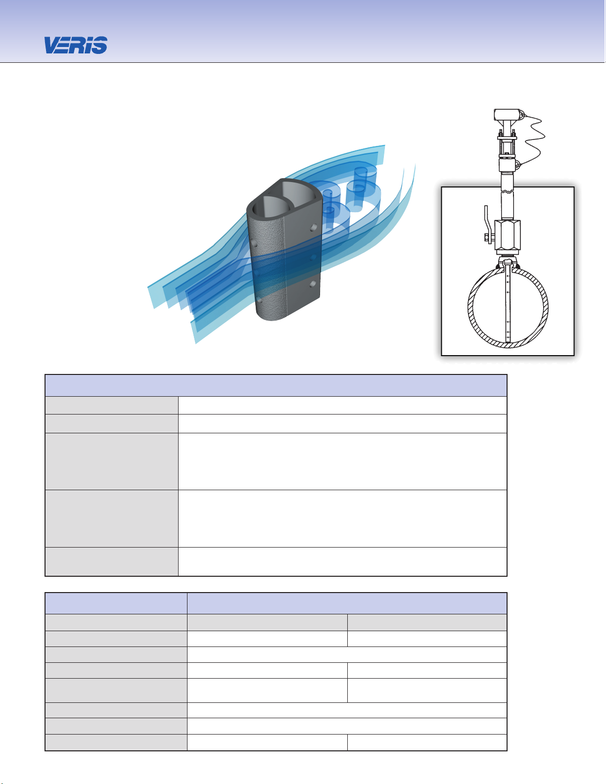
V250 Hot Tap
Pipe Connection Threaded (NPT)
Mounting Type Ball or gate access valve
• Lowest cost hot tap model
• Installation, insertion & retraction without system shutdown
Features and Benefits • Hand insertion and retraction for low pressures (no threaded rods)
• Retaining ring loads sensor to the opposite wall
• Can mount to existing valves
• Low pressure
• Air
Applications • Stack/flue gas
• Water
• Hydrocarbon and other gases
Special Designs— • Custom mounting, lengths, materials, instrument connections, etc.
Consult Factory • Short straight run
Model Specifications V250
Sensor Code 10 15
Sensor Diameter 7/8” (22mm) 1-3/8” (35mm)
Accuracy ±1% of flow rate; ±0.5% if calibrated
Max Pressure 30 psig (2.1 Bars) 10 psig (0.7 Bars)
Pipe Size
6”- 42” 12”-60”
(150mm-1050mm) (300mm-1500mm)
Instrument Connection 1/2” NPT or Direct Mount
Components Furnished Weld coupling, close nipple, access nipple and valve
Weld Coupling Size 1-1/4” NPT 2” NPT
The Most Accurate and Reliable Technology
for Measuring Gas, Liquid and Steam…
Developed from aerospace technology, the Verabar®
averaging pitot flow sensor provides unsurpassed
accuracy and reliability. With its solid, one-piece
construction and bullet shape, the Verabar
makes flow measurement leak proof
and precise.
The unique sensor shape
reduces drag and flow
induced vibration.
The location of the
low-pressure ports
eliminates the potential
for clogging and improves
signal stability.
Model
V250
Page 2
Verabar
®
Verabar
Flow Calculation
Program
Flow Calculation
Program
5.
Flow Calculation
All Verabar applications require a flow calculation to verify
the DP, pressure and temperature limits, structural limits
and to size the transmitter. The Veracalc PC Program
is for use by representatives and end users. It is easy
to operate and includes steam tables.
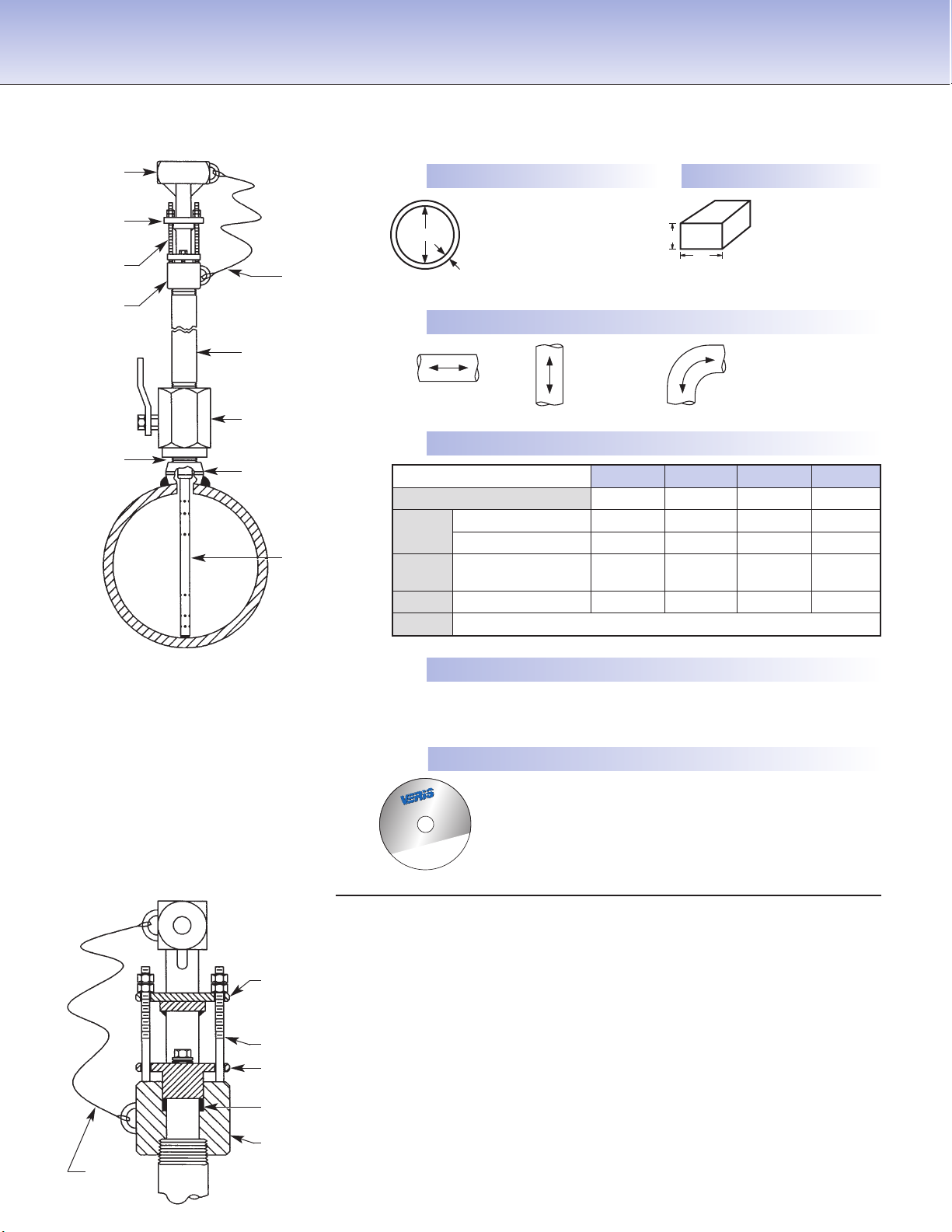
Retaining Hardware
• Eliminates drive rods
• Safety cable limits retraction length to ensure proper sealing
of packing gland
• Retaining ring loads sensor to opposite pipe wall
V250 Low Pressure
Verabar®Hot Tap Models
Instrument
head (SS)
Retaining
ring (SS)
Packing
gland (SS)
Studs & nuts
(SS)
Retaining ring
(SS)
Access nipple (CS)
(SS-opt)
Access valve
(CS, SS or BRZ)
Follower (SS)
Weld coupling
(CS) (SS-opt)
Close nipple
(SS)
Sensor
(316SS)
4.
Select Model from Page 3
Use the Ordering Information table on Page 3 to determine your
model number.
Short
Straight Run
Consult Factory
(V) Vertical
(H) Horizontal
Pipe Size _____ Sch _____
Pipe ID _____ and
Wall _____ Pipe Mat’l _____
Wall
Height (H) _____
Width (W) _____
Wall _____
Duct Mat’l _____
Dimension
Verabar spans
(H) or (W)
Fluid Name: Maximum Normal Minimum Units
Flow Rate
All
Temperature @ Flow
Fluids
Pressure @ Flow
Gas
Specific Gravity, or
Molecular Weight
Liquid Specific Gravity
Steam Veracalc Program can calculate Density from Temperature and Pressure
ID
W
H
2.
Pipe or Duct Orientation
3.
Enter Flow Conditions
1.
Enter Pipe Dimensions or Duct Dimensions
Furnish the following information:
Safety
cable (SS)
Safety
cable (SS)
Safety studs (SS)
Packing gland
(SS)
Model V250
Graphite packing
Page 3

Mounting Assembly — Select Valve Type & Material
(Includes valve, close nipple & weld coupling)
Sensor (Valve Size NPT)
10 (1-1/4”) 15 (2”) Type & Material
Code
B5B B8B Ball, Brz
B5C B8C Ball, CS
B5S B8S Ball, SS
G5C G8C Gate, CS
G5S G8S Gate, SS
Code Options
SS Wetted Components
WPS
(Furnished with SS weld coupling, close & access nipple).
Must be ordered with SS access valve.
V250 8”sch40 10 H R C2NC B5C Typical Model Number
Ordering Information
Instrument Valves (Opt.) Manifolds (Optional)
Remote Mount Direct Mount
Needle Gate 3-Valve 5-Valve
C2NC (CS) C2GC (CS) F3SC (CS) F3HC (CS) F5SC (CS) F5HC(CS)
C2NS (SS) C2GS (SS) F3SS (SS) F3HS (SS) F5SS (SS) F5HS (SS)
1/2” NPT Soft Seat Hard Seat Soft Seat Hard Seat1/2” NPT
Model Hot Tap • Threaded Pipe Connections and Components
V250 Hand Insert/Retract, Low Pressure
Pipe Size and Schedule or Exact ID and Wall Thickness
Code Sensor Pipe Size Range
10 6” to 42” (150mm to 1050mm)
15 12” to 60” (300mm to 1500mm)
Code Pipe Orientation
H Horizontal
V Vertical
Instrument Connections
(Select Remote or Direct Mount)
(Transmitter sold separately)
Remote Mount Transmitter Direct Mount Transmitter
(1/2” NPT) (Flanged 450°F/232°C Max.)†
Parallel Regular RTD
*
Valve Transmount Mass Transmount
*
Manifold
PR D T F G E M
Explsn. Proof
Remote
RTD
Integral
RTD
Integral
Integral
Optional
*
For high pressure (>500psig) or high temperature (>500°F), remote mount RTD in a thermowell is preferred.
† Assuming adequate heat dissipation for transmitter.
Page 4

6315 Monarch Park Place •Niwot, CO 80503 USA •Phone: 303-652-8550 •Fax: 303-652-8552
E-Mail: contact@veris-inc.com
•
Website: www.veris-inc.com
True Performance in DP Flow Measurement
PSS-250 (1/07)
Printed in USA
ISO 9001 Certified
 Loading...